EP3518601A2 - Verfahren und vorrichtung zur planung eines uplink-steuerkanals in einem drahtlosen netzwerk der nächsten generation - Google Patents
Verfahren und vorrichtung zur planung eines uplink-steuerkanals in einem drahtlosen netzwerk der nächsten generation Download PDFInfo
- Publication number
- EP3518601A2 EP3518601A2 EP17865477.8A EP17865477A EP3518601A2 EP 3518601 A2 EP3518601 A2 EP 3518601A2 EP 17865477 A EP17865477 A EP 17865477A EP 3518601 A2 EP3518601 A2 EP 3518601A2
- Authority
- EP
- European Patent Office
- Prior art keywords
- control channel
- timing relationship
- transmitting
- configuration information
- channel
- Prior art date
- Legal status (The legal status is an assumption and is not a legal conclusion. Google has not performed a legal analysis and makes no representation as to the accuracy of the status listed.)
- Granted
Links
Images



Classifications
-
- H—ELECTRICITY
- H04—ELECTRIC COMMUNICATION TECHNIQUE
- H04L—TRANSMISSION OF DIGITAL INFORMATION, e.g. TELEGRAPHIC COMMUNICATION
- H04L1/00—Arrangements for detecting or preventing errors in the information received
- H04L1/12—Arrangements for detecting or preventing errors in the information received by using return channel
- H04L1/16—Arrangements for detecting or preventing errors in the information received by using return channel in which the return channel carries supervisory signals, e.g. repetition request signals
- H04L1/18—Automatic repetition systems, e.g. Van Duuren systems
- H04L1/1867—Arrangements specially adapted for the transmitter end
- H04L1/1896—ARQ related signaling
-
- H—ELECTRICITY
- H04—ELECTRIC COMMUNICATION TECHNIQUE
- H04L—TRANSMISSION OF DIGITAL INFORMATION, e.g. TELEGRAPHIC COMMUNICATION
- H04L1/00—Arrangements for detecting or preventing errors in the information received
- H04L1/12—Arrangements for detecting or preventing errors in the information received by using return channel
- H04L1/16—Arrangements for detecting or preventing errors in the information received by using return channel in which the return channel carries supervisory signals, e.g. repetition request signals
- H04L1/18—Automatic repetition systems, e.g. Van Duuren systems
- H04L1/1812—Hybrid protocols; Hybrid automatic repeat request [HARQ]
-
- H—ELECTRICITY
- H04—ELECTRIC COMMUNICATION TECHNIQUE
- H04L—TRANSMISSION OF DIGITAL INFORMATION, e.g. TELEGRAPHIC COMMUNICATION
- H04L5/00—Arrangements affording multiple use of the transmission path
- H04L5/0091—Signalling for the administration of the divided path, e.g. signalling of configuration information
- H04L5/0094—Indication of how sub-channels of the path are allocated
-
- H—ELECTRICITY
- H04—ELECTRIC COMMUNICATION TECHNIQUE
- H04L—TRANSMISSION OF DIGITAL INFORMATION, e.g. TELEGRAPHIC COMMUNICATION
- H04L1/00—Arrangements for detecting or preventing errors in the information received
- H04L1/12—Arrangements for detecting or preventing errors in the information received by using return channel
- H04L1/16—Arrangements for detecting or preventing errors in the information received by using return channel in which the return channel carries supervisory signals, e.g. repetition request signals
- H04L1/18—Automatic repetition systems, e.g. Van Duuren systems
-
- H—ELECTRICITY
- H04—ELECTRIC COMMUNICATION TECHNIQUE
- H04L—TRANSMISSION OF DIGITAL INFORMATION, e.g. TELEGRAPHIC COMMUNICATION
- H04L1/00—Arrangements for detecting or preventing errors in the information received
- H04L1/12—Arrangements for detecting or preventing errors in the information received by using return channel
- H04L1/16—Arrangements for detecting or preventing errors in the information received by using return channel in which the return channel carries supervisory signals, e.g. repetition request signals
- H04L1/18—Automatic repetition systems, e.g. Van Duuren systems
- H04L1/1829—Arrangements specially adapted for the receiver end
- H04L1/1854—Scheduling and prioritising arrangements
-
- H—ELECTRICITY
- H04—ELECTRIC COMMUNICATION TECHNIQUE
- H04L—TRANSMISSION OF DIGITAL INFORMATION, e.g. TELEGRAPHIC COMMUNICATION
- H04L27/00—Modulated-carrier systems
-
- H—ELECTRICITY
- H04—ELECTRIC COMMUNICATION TECHNIQUE
- H04L—TRANSMISSION OF DIGITAL INFORMATION, e.g. TELEGRAPHIC COMMUNICATION
- H04L27/00—Modulated-carrier systems
- H04L27/26—Systems using multi-frequency codes
- H04L27/2601—Multicarrier modulation systems
- H04L27/2602—Signal structure
- H04L27/26025—Numerology, i.e. varying one or more of symbol duration, subcarrier spacing, Fourier transform size, sampling rate or down-clocking
-
- H—ELECTRICITY
- H04—ELECTRIC COMMUNICATION TECHNIQUE
- H04L—TRANSMISSION OF DIGITAL INFORMATION, e.g. TELEGRAPHIC COMMUNICATION
- H04L5/00—Arrangements affording multiple use of the transmission path
- H04L5/0001—Arrangements for dividing the transmission path
- H04L5/0003—Two-dimensional division
- H04L5/0005—Time-frequency
- H04L5/0007—Time-frequency the frequencies being orthogonal, e.g. OFDM(A) or DMT
- H04L5/001—Time-frequency the frequencies being orthogonal, e.g. OFDM(A) or DMT the frequencies being arranged in component carriers
-
- H—ELECTRICITY
- H04—ELECTRIC COMMUNICATION TECHNIQUE
- H04L—TRANSMISSION OF DIGITAL INFORMATION, e.g. TELEGRAPHIC COMMUNICATION
- H04L5/00—Arrangements affording multiple use of the transmission path
- H04L5/003—Arrangements for allocating sub-channels of the transmission path
- H04L5/0053—Allocation of signalling, i.e. of overhead other than pilot signals
- H04L5/0055—Physical resource allocation for ACK/NACK
-
- H—ELECTRICITY
- H04—ELECTRIC COMMUNICATION TECHNIQUE
- H04W—WIRELESS COMMUNICATION NETWORKS
- H04W72/00—Local resource management
- H04W72/12—Wireless traffic scheduling
- H04W72/1263—Mapping of traffic onto schedule, e.g. scheduled allocation or multiplexing of flows
-
- H—ELECTRICITY
- H04—ELECTRIC COMMUNICATION TECHNIQUE
- H04W—WIRELESS COMMUNICATION NETWORKS
- H04W72/00—Local resource management
- H04W72/12—Wireless traffic scheduling
- H04W72/1263—Mapping of traffic onto schedule, e.g. scheduled allocation or multiplexing of flows
- H04W72/1268—Mapping of traffic onto schedule, e.g. scheduled allocation or multiplexing of flows of uplink data flows
-
- H—ELECTRICITY
- H04—ELECTRIC COMMUNICATION TECHNIQUE
- H04W—WIRELESS COMMUNICATION NETWORKS
- H04W72/00—Local resource management
- H04W72/20—Control channels or signalling for resource management
- H04W72/23—Control channels or signalling for resource management in the downlink direction of a wireless link, i.e. towards a terminal
- H04W72/232—Control channels or signalling for resource management in the downlink direction of a wireless link, i.e. towards a terminal the control data signalling from the physical layer, e.g. DCI signalling
-
- H—ELECTRICITY
- H04—ELECTRIC COMMUNICATION TECHNIQUE
- H04W—WIRELESS COMMUNICATION NETWORKS
- H04W72/00—Local resource management
- H04W72/20—Control channels or signalling for resource management
- H04W72/21—Control channels or signalling for resource management in the uplink direction of a wireless link, i.e. towards the network
Definitions
- the present disclosure relates to methods of scheduling an uplink control channel (PUCCH) for hybrid automatic repeat request (HARQ) acknowledge/negative-acknowledge (ACK/NACK) feedback on a downlink data channel (PDSCH) in a next-generation/5G radio access network (hereinafter, referred to as a new radio (NR)) that is under discussion in the 3rd generation partnership project (3GPP).
- PUCCH uplink control channel
- HARQ hybrid automatic repeat request
- ACK/NACK acknowledge/negative-acknowledge
- PDSCH downlink data channel
- NR next-generation/5G radio access network
- Radio Access Network Working Group 1 (RAN WG1) has been discussing frame structures, channel coding and modulation, waveforms, multiple access methods, and the like for the new radio (NR). It is required to design the NR not only to provide an improved data transmission rate as compared with the long term evolution (LTE)/LTE-Advanced, but also to meet various requirements in detailed and specific usage scenarios.
- an enhanced mobile broadband (eMBB), massive machine-type communication (mMTC), and ultra reliable and low latency communication (URLLC) are proposed as representative usage scenarios of the NR.
- eMBB enhanced mobile broadband
- mMTC massive machine-type communication
- URLLC ultra reliable and low latency communication
- the NR supports a frame structure supporting a plurality of numerologies with subcarrier spacing (SCS) values different from one another and further supports scheduling time intervals different from one another.
- SCS subcarrier spacing
- PUCCH uplink control channel
- PDSCH downlink data channel
- a method of a user equipment for scheduling an uplink control channel (PUCCH).
- the method includes: receiving timing relationship configuration information between a downlink data channel (PDSCH) and the uplink control channel (PUCCH) from a base station, and scheduling the uplink control channel (PUCCH) based on the timing relationship configuration information.
- the uplink control channel (PUCCH) includes HARQ ACK/NACK feedback information on the downlink data channel (PDSCH), and a numerology used for receiving the downlink data channel (PDSCH) and a numerology used for transmitting the uplink control channel (PUCCH) are different from each other.
- a method of a base station for scheduling an uplink control channel (PUCCH).
- the method includes: composing timing relationship configuration information between a downlink data channel (PDSCH) and the uplink control channel (PUCCH), and transmitting the timing relationship configuration information to a user equipment.
- the uplink control channel (PUCCH) includes HARQ ACK/NACK feedback information on the downlink data channel (PDSCH), and a numerology used for transmitting the downlink data channel (PDSCH) and a numerology used for receiving the uplink control channel (PUCCH) are different from each other.
- a user equipment for scheduling an uplink control channel (PUCCH).
- the user equipment includes: a receiver configured to receive timing relationship configuration information between a downlink data channel (PDSCH) and the uplink control channel (PUCCH) from a base station, and a controller configured to schedule the uplink control channel (PUCCH) based on the timing relationship configuration information.
- the uplink control channel (PUCCH) includes HARQ ACK/NACK feedback information on the downlink data channel (PDSCH), and a numerology used for receiving the downlink data channel (PDSCH) and a numerology used for transmitting the uplink control channel (PUCCH) are different from each other.
- a base station for scheduling an uplink control channel (PUCCH).
- the base station includes: a controller configured to compose timing relationship configuration information between a downlink data channel (PDSCH) and the uplink control channel (PUCCH), and a transmitter configured to transmit the timing relationship configuration information to a user equipment.
- the uplink control channel (PUCCH) includes HARQ ACK/NACK feedback information on the downlink data channel (PDSCH), and a numerology used for transmitting the downlink data channel (PDSCH) and a numerology used for receiving the uplink control channel (PUCCH) are different from each other.
- timing relationship configuration information based on a reference numerology in the case of supporting a plurality of numerologies in an NR system, and ii) to provide a method of scheduling an uplink control channel (PUCCH) including HARQ ACK/NACK feedback information on a downlink data channel (PDSCH) between a user equipment and a base station based on the composed timing relationship configuration information,.
- PUCCH uplink control channel
- PDSCH downlink data channel
- a wireless communication system refers to a system for providing various communication services such as a voice communication service, a packet data service, etc.
- the wireless communication system includes user equipment (UE) and a base station (BS).
- UE user equipment
- BS base station
- the UE is a generic term referring to devices used in wireless communication.
- the UE may be referred to, but not limited to, a UE supporting wideband code division multiple access (WCDMA), long term evolution (LTE), high speed packet access (HSPA), international mobile telecommunications (IMT)-2020 (5G or new radio), or the like, a mobile station (MS) supporting the global system for mobile communication (GSM), a user terminal (UT), a subscriber station (SS), a wireless device, or the like.
- WCDMA wideband code division multiple access
- LTE long term evolution
- HSPA high speed packet access
- IMT international mobile telecommunications
- GSM global system for mobile communication
- UT user terminal
- SS subscriber station
- wireless device or the like.
- the BS or a cell generally refers to a station communicating with the UE.
- the BS or the cell is a generic term referring to, but not limited to, all of various communication service areas and devices, such as a Node-B, an evolved Node-B (eNB), a gNode-B (gNB), a low power node (LPN), a sector, a site, various types of antennas, a base transceiver system (BTS), an access point, a point (e.g., a transmitting point, a receiving point, or a transceiving point), a relay node, a megacell, a macrocell, a microcell, a picocell, a femtocell, a remote radio head (RRH), a radio unit (RU), and a small cell.
- a Node-B an evolved Node-B (eNB), a gNode-B (gNB), a low power node (LPN), a sector,
- the BS may be classified into two categories. 1)
- the BS may be referred to an apparatus that forms and provides a corresponding communication service area, such as a megacell, a macrocell, a microcell, a picocell, a femtocell, and a small cell, or 2) the BS may be referred to a communication service area.
- the BS may be referred to i) apparatuses that form and provide any corresponding communication service area and are controlled by the same entity, or ii) apparatus that interact and cooperate with each other for forming and providing the corresponding communication service area.
- the BS may be referred to as a point, a transmission/reception point, a transmission point, a reception point, or the like.
- the BS may be a communication service area itself where UEs able to receive signals from or transmit signals to other UEs and neighboring BSs.
- the cell may also refer to a coverage of a signal transmitted from a transmission/reception point, a component carrier having the coverage of a signal transmitted from a transmission point or a transmission/reception point, or a transmission/reception point itself.
- the UE and the BS are two entities for performing transmission/reception used to embody the technology and technical spirit described in the present specification.
- the UE and the BS are a generic term and not limited to specific terms or words.
- the uplink (UL) refers to data transmission/reception by a UE to/from a BS
- the downlink (DL) refers to data transmission/reception by a BS to/from a UE.
- UL transmission and DL transmission may be performed by employing i) a time division duplex (TDD) technique performing transmission through different time slots, ii) a frequency division duplex (FDD) technique performing transmission through different frequencies, or ii) a hybrid technique of the frequency division duplex (FDD) and the time division duplex (TDD).
- TDD time division duplex
- FDD frequency division duplex
- TDD time division duplex
- the related standard of the wireless communication system defines configuring the UL and the DL based on a single carrier or a pair of carriers.
- the UL and the DL transmit control information through one or more control channels, such as a physical DL control channel (PDCCH), a physical UL control channel (PUCCH), and the like.
- the UL and DL transmit data through data channels, such as a physical DL shared channel (PDSCH), a physical UL shared channel (PUSCH), and the like.
- the DL may denote communication or a communication path from multiple transmission/reception points to a UE, and the UL may denote communication or a communication path from the UE to the multiple transmission/reception points.
- a transmitter may be a part of multiple transmission/reception points, and a receiver may be a part of a UE.
- a transmitter may be a part of a UE, and a receiver may be a part of multiple transmission/reception points.
- transmission and reception of a signal through a channel such as the PUCCH, the PUSCH, the PDCCH, or the PDSCH, may be described as the transmission and reception of the channel, such as the PUCCH, the PUSCH, the PDCCH, or the PDSCH.
- higher layer signaling includes radio resource control (RRC) signaling transmitting RRC information containing an RRC parameter.
- RRC radio resource control
- the BS performs DL transmission to UEs.
- the BS may transmit a physical DL control channel for transmitting i) DL control information, such as scheduling required to receive a DL data channel that is a primary physical channel for unicast transmission, and ii) scheduling approval information for transmission through an UL data channel.
- DL control information such as scheduling required to receive a DL data channel that is a primary physical channel for unicast transmission
- ii) scheduling approval information for transmission through an UL data channel ii) scheduling approval information for transmission through an UL data channel.
- the wireless communication system may employ various multiple access techniques, such as time division multiple access (TDMA), frequency division multiple access (FDMA), CDMA, orthogonal frequency division multiple access (OFDMA), non-orthogonal multiple access (NOMA), OFDM-TDMA, OFDM-FDMA, OFDM-CDMA, or the like.
- TDMA time division multiple access
- FDMA frequency division multiple access
- OFDMA orthogonal frequency division multiple access
- NOMA non-orthogonal multiple access
- OFDM-TDMA OFDM-TDMA
- OFDM-FDMA OFDM-FDMA
- OFDM-CDMA OFDM-CDMA
- NOMA includes sparse code multiple access (SCMA), low cost spreading (LDS), and the like.
- At least one embodiment of the present disclosure may be applied to resource allocation in i) asynchronous wireless communication evolving into LTE/LTE-advanced and IMT-2020 from GSM, WCDMA, and HSPA, ii) synchronous wireless communication evolving into CDMA, CDMA-2000, and UMB.
- a machine type communication (MTC) terminal may refer to a terminal supporting low costs (or low complexity), a terminal supporting coverage enhancement, or the like.
- the MTC terminal may refer to a terminal defined as a predetermined category for supporting low cost (or low complexity) and/or coverage enhancement.
- the MTC terminal may refer to a low cost (or low complexity) UE category/type newly defined in 3GPP Release-13 and performing LTE-based MTC-related operations.
- the MTC terminal may refer to a UE category/type defined in or before 3GPP Release-12, which supports enhanced coverage in comparison with the typical LTE coverage or supports low power consumption.
- the MTC device may refer to a low cost (or low complexity) UE category/type newly defined in Release-13.
- the MTC terminal may refer to a further enhanced MTC terminal defined in Release-14.
- NB-IoT narrowband Internet of Things
- NB-IoT technology aims at improved indoor coverage, support for large-scale low-speed terminals, low latency sensitivity, very low terminal costs, low power consumption, and optimized network architecture.
- eMBB enhanced mobile broadband
- mMTC massive machine-type communication
- URLLC ultra reliable and low latency communication
- a frequency, a frame, a subframe, a resource, a resource block (RB), a region, a band, a sub-band, a control channel, a data channel, a synchronization signal, various reference signals, various signals, and various messages associated with NR of the present disclosure may be interpreted as being used in the past or present or as various meanings to be used in the future.
- the NR It is required to design the NR not only to provide improved data transmission rates compared with the long term evolution (LTE)/LTE-Advanced, but also to meet various requirements in detailed and specific usage scenarios.
- LTE long term evolution
- eMBB enhanced mobile broadband
- mMTC massive machine-type communication
- URLLC ultra reliable and low latency communication
- the eMBB, mMTC, URLLC are considered as representative usage scenarios of the NR by the 3GPP.
- Each usage scenario imposes different requirements for data rates, latency, coverage, etc.
- numerologies e.g., a subcarrier spacing (SCS), a subframe, a transmission time interval (TTI), etc.
- a definition of a subframe has been given as one type of a time domain structure.
- a reference numerology to define a corresponding subframe duration a single subframe duration is defined as having 14 OFDM symbols of normal CP overhead based on 15 kHz subcarrier spacing (SCS), like the LTE.
- the subframe of the NR has the time duration of 1 ms.
- a slot and a minislot may be defined as a time unit served as a basis of actual UL/DL data scheduling.
- a slot may be formed of 14 symbols.
- all symbols may be used for DL transmission or UL transmission, or the symbols may be used in the configuration of a DL portion + a gap + an UL portion.
- a minislot formed of fewer symbols than the slot has been defined in a numerology (or SCS).
- a time-domain scheduling interval with a short length may be configured for UL/DL data transmission/reception based on the minislot.
- a time-domain scheduling interval with a long length may be configured for UL/DL data transmission/reception by slot aggregation.
- the feedback timing is i) dynamically configured by L1 signaling (e.g. DCI), ii) semi-statically configured through higher layer, or iii) configured in combination of the higher layer and the dynamical L1 signaling.
- L1 signaling e.g. DCI
- the timing is i) dynamically configured by L1 signaling (e.g. DCI), ii) semi-statically configured through higher layer, or iii) configured in combination of the higher layer and the dynamical L1 signaling.
- L1 signaling e.g. DCI
- timing between DL assignment and corresponding DL data reception is i) dynamically configured by L1 signaling (e.g. DCI), ii) semi-statically configured through higher layer, or iii) configured in combination of the higher layer and the dynamical L1 signaling.
- L1 signaling e.g. DCI
- the NR is designed to support a plurality of numerologies and support different scheduling time intervals (e.g., a slot or a mini-slot, or slot aggregation) from one another, it is necessary to solve ambiguity between a UE and a BS, which is resulted from defining i) timing relationship related to the DCI and corresponding DL/UL data timing, and ii) timing relationship related to DL data reception and corresponding HARQ ACK/NACK feedback timing.
- a BS and a UE for indicating and interpreting respectively i) timing between a DL control channel (i.e. NR PDCCH) for transmitting DL control information (DCI) including data scheduling information for any NR UE and corresponding DL or UL data reception, and ii) timing between DL data reception and corresponding HARQ ACK/NACK feedback of the UE.
- a DL control channel i.e. NR PDCCH
- DCI DL control information
- DCI DL control information
- Discussions have been conducted on a frame structure for supporting a plurality of numerologies with subcarrier spacing values different from one another in the NR.
- the lengths of OFDM symbols depending on SCS values for each numerology may be different as shown in FIG. 1 , and the lengths of slots formed with an identical y value may be also different depending on SCS values.
- the lengths of the corresponding slots are respectively 1ms and 0.5ms.
- time-domain scheduling intervals different from one another may be defined in an identical numerology, such as, defining a slot formed of 14 symbols as a unit of scheduling in the time domain for each UE, defining a minislot formed of fewer symbols than a slot, defining a time-domain scheduling unit through slot aggregation where a plurality of slots is aggregated, or the like.
- a scheduling unit and a corresponding DL control channel monitoring unit in each CC may be 1ms in the CC #1 and 0.25ms in the CC #2.
- timing relationship between the DCI and corresponding data or data and corresponding ACK/NACK feedback is configured with any k value, it is necessary to define whether the timing length served as the reference of the k is 1ms or 0.25ms.
- timing gap information information on timing relationship (e.g. timing gap information) between UL assignment and corresponding UL data transmission
- L1 signaling namely corresponding UL assignment DCI
- a timing gap, k configured through the UL assignment DCI
- the scheduling interval served as a reference is i) a slot (e.g., 1ms) formed of 14 symbols based on 15kHz which is the scheduling interval of the CC #1 or ii) a slot (e.g., 0.25ms) formed of 14 symbols based on 60kHz which is the scheduling interval of the CC #2.
- Embodiments described below may be applied to all UEs, BSs, and core network entities (MME) using mobile communication technologies.
- MME core network entities
- embodiments of the present disclosure may be applied not only to mobile communication UEs employing long term evolution technology, but also to next generation mobile communication (5G mobile communication, New-RAT) UEs, BSs, and access and mobility functions (AMFs).
- a BS may denote an eNB of LTE/E-UTRAN, or denote at least one of a central unit (CU), a distribute unit (DU), and an object in which the CU and the DU are implemented as one logical object, or a gNB, in a 5G radio network in which the CU is separated from the DU.
- the numerology denotes numerical characteristics and numerical values for data transmission/reception.
- the numerology may be determined depending on a value of the subcarrier spacing (hereinafter, referred to as SCS or subcarrier spacing). Accordingly, that numerologies are different may mean that subcarrier spacings determining the numerologies are different.
- an example of the timing relationship in the present disclosure may mean timing between i) a DL data channel (PDSCH) for receiving DL data of a UE and ii) an UL control channel (PUCCH) for transmitting corresponding HARQ ACK/NACK feedback to a BS.
- PDSCH DL data channel
- PUCCH UL control channel
- Timing relationship configuration information means information used for configuring the timing relationship and may be expressed as timing granularity.
- the timing relationship configuration information may include information on the time domain scheduling interval (TTI) and a timing gap used for indicating it, a time unit, a slot length, a slot index, and a reference slot index.
- TTI time domain scheduling interval
- the slot length in the present disclosure may be expressed as the number of OFDM symbols forming a slot or as a time occupied by the slot.
- the length of one symbol may be expressed as 14 OFDM symbols, or expressed as 1ms.
- FIG. 3 is a flowchart illustrating a procedure of a UE for scheduling an uplink control channel (PUCCH) according to at least one embodiment of the present disclosure.
- PUCCH uplink control channel
- the UE may receive timing relationship configuration information between a DL data channel (PDSCH) and an UL control channel (PUCCH) from a BS (S300).
- PDSCH DL data channel
- PUCCH UL control channel
- numerologies used by the UE in the UL and the DL may be different from each other.
- numerologies between respective component carriers may be different from each other.
- that numerologies are different means that subcarrier spacing values determining the numerologies are different, and therefore, subcarrier spacing values used by the UE in the UL and the DL may be different from each other.
- a subcarrier spacing value used for receiving the DL data channel may be different from a subcarrier spacing value used for transmitting the UL control channel.
- a component carrier used for receiving the DL data channel may be different from a component carrier used for transmitting the UL control channel.
- a carrier used for receiving the DL data channel may be the same as that used for transmitting the UL control channel.
- the UL control channel may be transmitted through supplementary UL (SUL) used for transmitting the UL control channel.
- the BS may compose timing relationship configuration information based on a reference numerology, and then the UE may receive and use the timing relationship configuration information from the BS.
- the UE may receive the timing relationship configuration from the BS through DCI signaling.
- the UE may detect the DCI received through the DL control channel (PDCCH) and use the timing relationship configuration information contained in the DCI.
- PDCCH DL control channel
- the UE may receive the timing relationship configuration information from the BS through high layer signaling. That is, it is possible for the UE to receive the timing relationship configuration information through UE-specific RRC signaling from the BS.
- the UE may schedule the UL control channel based on the timing relationship configuration information received form the BS (S310).For example, when a timing gap value between data received through DL data channel and corresponding HARQ ACK/NACK feedback data is k, the UE may interpret the timing gap value based on a slot length defined in the timing relationship configuration information and schedule UL control channel based on the interpreted value.
- the timing relationship configuration information may be composed in a slot unit based on the numerology used for transmitting the UL control channel. That is, when the UE interprets timing relationship between the DL data channel and the UL control channel including the corresponding HARQ ACK/NACK feedback information according to the timing relationship configuration information, the timing relationship may be interpreted based on a numerology used for transmitting the UL control channel. In this case, even though the DL data channel is transmitted on a per minislot basis, the UL data control channel may be transmitted only on a per slot basis.
- FIG. 4 is a flowchart illustrating a procedure of a BS for scheduling an UL control channel, according to at least one embodiment of the present disclosure.
- the BS may compose timing relationship configuration information between a DL data channel (PDSCH) and an UL control channel (PUCCH) (S400).
- PDSCH DL data channel
- PUCCH UL control channel
- numerologies used by any UE in the UL and the DL may be different from each other.
- numerologies between respective component carriers may be different from each other.
- that numerologies are different means that subcarrier spacings determining the numerologies are different, and therefore, subcarrier spacings used by the UE in the UL and the DL may be different from each other.
- a subcarrier spacing used for the DL data channel may be different from a subcarrier spacing used for the UL control channel.
- a component carrier used for transmitting the DL data channel may be different from a component carrier used for receiving the UL control channel, by the BS.
- a carrier used for transmitting the DL data channel may be the same as that used for receiving the UL control channel.
- the UL control channel may be transmitted through supplementary UL (SUL) used for transmitting the UL control channel.
- SUL supplementary UL
- the BS may compose timing relationship configuration information based on a reference numerology, and then the UE may receive and use the timing relationship configuration information from the BS.
- the BS may transmit the timing relationship configuration information to the UE (S410).
- the BS may transmit the timing relationship configuration to the UE through DCI signaling.
- the UE may detect the DCI received through the DL control channel (PDCCH) and use the timing relationship configuration information contained in the DCI.
- PDCCH DL control channel
- the BS may transmit the timing relationship configuration information to the UE through high layer signaling. That is, it is possible for the BS to transmit the timing relationship configuration information through UE-specific RRC signaling to the UE.
- the timing relationship configuration information may be composed in a slot unit based on the numerology used for transmitting the UL control channel. That is, when the BS composes the timing relationship configuration information between the DL data channel and the UL control channel including the corresponding HARQ ACK/NACK feedback information, the timing relationship configuration information may be composed based on a numerology used for transmitting the UL control channel. In this case, even though the DL data channel is transmitted on a per minislot basis, the UL data control channel may be transmitted only on a per slot basis.
- the embodiments may be i) for a case where a DL numerology for transmitting UL assignment DCI and a UL numerology for transmitting corresponding data are configured differently or ii) for a case where a time-domain scheduling interval of the DL for transmitting the UL assignment DCI may be configured based on a slot and a time-domain scheduling interval for transmitting corresponding UL data may be configured based on a minislot.
- the present disclosure may be applied to i) all cases where time-domain scheduling intervals for the DCI and corresponding data transmission are different or ii) all cases where time-domain scheduling intervals for DL data reception and an NR PUCCH configuration for corresponding HARQ ACK/NACK feedback UCI transmission are different.
- the timing relationship related information may be defined to be configured by a BS or interpreted by a UE, based on an actual time-domain scheduling interval (or TTI) for transmitting UL data transmission or receiving DL data reception corresponding to the DCI.
- a NR UE is configured to support carrier aggregation (CA) of the CC #1 of 15kHz SCS and the CC #2 of 60kHz SCS.
- CA carrier aggregation
- timing relationship (e.g., k value)between i) data of the CC #2 transmitted through the DCI or configured through higher layer and ii) the DCI including corresponding scheduling information
- k value e.g., k value
- the DCI including corresponding scheduling information may be defined to beset by a BS and to be interpreted by a UE based on a unit of the time-domain scheduling interval (or TTI) of the CC#2 for transmitting/receiving corresponding data.
- timing relationship related information is indication information on a timing gap between the DCI and corresponding data transmission/reception and when the timing gap is set to k
- the timing relationship may be defined to perform corresponding data transmission/receptionafter k slots (i.e., through a slot of the first CC # 2 after k ⁇ 0.25 ms) based on a slot unit of 0.25ms length of 60kHz SCS which is the time-domain scheduling interval (or TTI) of the CC #2 for transmitting the DCI, not a slot unit of 1ms length of 15kHz SCS which is the time-domain scheduling interval (or TTI) of the CC #1 for transmitting the DCI.
- timing indication and timing interpretation with respect to a difference between i) the SCS value for transmitting the PDSCH and a corresponding DL slot length and ii) the SCS value for transmitting the PUCCH for HARQ ACK/NACK feedback of a UE and a corresponding UL slot length.
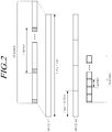
- FIG. 2 is a diagram illustrating carrier aggregation of a NR component carrier #1 with 15kHz subcarrier spacing and a NR component carrier #2 with 60kHz subcarrier spacing, according to at least one embodiment of the present disclosure.
- a slot length in the NR CC #1 is 1ms
- a slot length in the NR CC #2 is 0.25ms, which are different from each other.
- a DL (or UL) slot may be formed by an NR carrier/cell established in a high-frequency band, and the NR CC#1 may be configured by a carrier/cell, which is supplementary UL (SUL), established in a low-frequency band.
- the supplementary UL (SUL) means a separately established UL so that data can be transmitted to a BS through a low-frequency band, in order to address coverage issues that may occur when a UE transmits/receives data using a high-frequency band.
- the UE may perform, in the NR CC#1, PUCCH transmission for HARQ ACK/NACK feedback with respect to PDSCH transmission of the NR CC #2 .
- the corresponding k1 value may be defined to be set by the BS and interpreted by the UE, based on the slot length of the NR CC#1 for transmitting the PUCCH including the corresponding HARQ ACK/NACK feedback in the NR CC #1. That is, in the example illustrated in FIG.
- the k1 value may be set and interpreted, based on a unit of 1ms, which is the UL slot length of the NR CC#1 for transmitting the PUCCH.
- a reference numerology served as a reference for composing timing relationship configuration information is the numerology of the NR CC#1 for transmitting the PUCCH.
- timing gap information between the PDSCH transmission in the NR CC #2 and the PUCCH transmission in the NR CC #1 (e.g., SUL) including the corresponding HARQ ACK/NACK feedback of the UE is composed by the BS and interpreted by the UE, based on a unit of the TTI or slot length, of 1 ms of the CC #1 for transmitting/receiving the PUCCH.
- corresponding timing gap information is set to k1
- the reference slot index may be defined depending on a ratio between a SCS for transmitting corresponding PDSCH and a SCS for transmitting corresponding PUCCH. More specifically, when a SCS of an NR CC for PDSCH transmission is A kHz (in this Embodiment, 60kHz of the NR CC #2), and a SCS of an NR CC for transmitting corresponding PUCCH is B kHz (in this Embodiment, 15kHz of the NR CC #1), if a slot index for transmitting the PDSCH in the NR CC #2 is n, a reference slot index in an NR CC (e.g., the NR CC#1) for transmitting the PUCCH for counting the timing gap for transmitting the PUCCH, k1 slot(s), may be defined as ⁇ n ⁇ B A ⁇ .
- a slot index through which the PDSCH is transmitted in the NR CC #2 is n
- a slot index through which the PUCCH is transmitted in the NR CC#1 may be defined as ⁇ n ⁇ B A ⁇ + k 1 depending on the timing gap, k1 value.
- ⁇ m ⁇ is a floor function, that is, the maximum integer less than or equal to m.
- a reference slot index may be defined as a slot index of the NR CC #1 for transmitting PUCCH which overlaps with at least one symbol for transmitting PDSCH or completing the PDSCH transmissionin the NR CC#2.
- a reference slot index may be defined as a slot index of the NR CC #1 for transmitting PUCCH which overlaps with at least one symbol for transmitting PDSCH or completing the PDSCH transmissionin the NR CC#2.
- the information on the timing relationship may be composed by a BS or interpreted by a UE based on a time-domain scheduling interval (or TTI) served as a transmission/reception unit for UL assignment or DL assignment DCI including scheduling information for the UL/DL data.
- TTI time-domain scheduling interval
- a NR UE is configured to support carrier aggregation (CA) of the CC #1 of 15kHz SCS and the CC #2 of 60kHz SCS.
- CA carrier aggregation
- timing relationship (e.g.,k value)between i) data transmission/reception in the CC #2 configured through the DCI or higher layer and ii) the DCI including corresponding scheduling information may be defined to beset by a BS/interpreted by a UE based on a unit of the time-domain scheduling interval (or TTI) of the CC#1 for transmitting the DCI.
- the timing relationship may be defined to transmit and receive corresponding data t after k slots (i.e., through a slot of the first CC # 2 after k ⁇ 1ms) based on a unit of 1ms slot of 15kHz SCS which is the time-domain scheduling interval (or TTI) of the CC #1 for transmitting the DCI, not a unit of 0.25ms slot of 60kHz SCS which is the time-domain scheduling interval (or TTI) of the CC #2 for transmitting/receiving the data.
- the BS As another method for synchronization between the timing relationship configuration of the BS and the timing relationship interpretation of the UE, it is possible for the BS to configure, semi-statically through higher layer signaling or dynamically through L1 signaling (e.g., L1/L2 control channel), a reference time-domain scheduling interval (or TTI) served as a reference of corresponding timing relationship indication.
- L1 signaling e.g., L1/L2 control channel
- TTI time-domain scheduling interval
- the configuration may be performed based on a unit of a reference numerology and the number of OFDM symbols.
- the configuration may be performed based on a time unit of ms, such as 1ms, 0.5ms, 0.25ms, 0.125ms, etc. served as a slot length for each numerology.
- Fig. 5 is a block diagram illustrating a BS 500 according to an embodiment of the present disclosure.
- the BS 500 includes a controller 510, a transmitter 520 and a receiver 530.
- the controller 510 is configured to compose timing relationship configuration information between a DL data channel (PDSCH) and an UL control channel (PUCCH).
- the timing relationship configuration information may be contained in DL control information (DCI) transmitted through the DL control channel.
- DCI DL control information
- the timing relationship configuration information may be transmitted to a UE through high layer signaling.
- the uplink control channel includes HARQ ACK/NACK feedback information on the downlink data channel (PDSCH).
- a numerology used for transmitting the downlink data channel (PDSCH) and a numerology used for receiving the uplink control channel (PUCCH) are different from each other.
- the timing relationship configuration information may be composed in a slot unit based on the numerology used for receiving the UL control channel. In this case, even though the DL data channel is transmitted on a per minislot basis, the UL data control channel may be received only on a per slot basis.
- a component carrier used for transmitting the DL data channel may be different from a component carrier used for receiving the UL control channel, by the BS.
- a carrier used for transmitting the DL data channel may be the same as that used for receiving the UL control channel.
- the UL control channel may be transmitted through supplementary UL (SUL) used for transmitting the UL control channel.
- SUL supplementary UL
- the transmitter 520 and the receiver 530 are used to transmit to and receive from a UE, signals, messages, and data necessary for carrying out the present disclosure described above.
- the transmitter 520 is configured to transmit the timing relationship configuration information to the UE.
- the UE may schedule the UL control channel based on the timing relationship configuration information received form the BS.
- Fig. 6 is a block diagram illustrating a UE 600 according to an embodiment of the present disclosure.
- the UE 600 includes a receiver 610, a controller 620 and a transmitter 630.
- the receiver 610 is configured to receive DL control information and data, messages through a corresponding channel from a BS. More specifically, the receiver 610 is configured to receive timing relationship configuration information between a DL data channel (PDSCH) and an UL control channel (PUCCH).
- PDSCH DL data channel
- PUCCH UL control channel
- the timing relationship configuration information may be contained in DL control information (DCI) received through the DL control channel.
- DCI DL control information
- the timing relationship configuration information may be transmitted to the UE through high layer signaling.
- the controller 620 is configured to schedule the UL control channel based on the timing relationship configuration information received from the BS.
- the UL control channel includes HARQ ACK/NACK feedback information on the DL data channel (PDSCH).
- a numerology used for receiving the DL data channel (PDSCH) and a numerology used for transmitting the UL control channel (PUCCH) are different from each other.
- the timing relationship configuration information may be composed in a slot unit based on the numerology used for receiving the UL control channel.
- the UL data control channel may be transmitted only on a per slot basis.
- the UL data control channel may be received only on a per slot basis.
- a component carrier used for receiving the DL data channel may be different from a component carrier used for transmitting the UL control channel.
- a carrier used for receiving the DL data channel may be the same as that used for transmitting the UL control channel.
- the UL control channel may be transmitted through supplementary UL (SUL) used for transmitting the UL control channel.
- the transmitter 630 is configured to transmit UL control information and data, messages through a corresponding channel to the BS.
Landscapes
- Engineering & Computer Science (AREA)
- Signal Processing (AREA)
- Computer Networks & Wireless Communication (AREA)
- Physics & Mathematics (AREA)
- Mathematical Physics (AREA)
- Mobile Radio Communication Systems (AREA)
Applications Claiming Priority (4)
| Application Number | Priority Date | Filing Date | Title |
|---|---|---|---|
| KR20160141451 | 2016-10-27 | ||
| KR1020170130023A KR20180046358A (ko) | 2016-10-27 | 2017-10-11 | 차세대 무선 액세스망을 위한 스케줄링 방법 및 장치 |
| KR1020170139598A KR102057127B1 (ko) | 2016-10-27 | 2017-10-25 | 차세대 무선망에서 상향 링크 제어 채널을 스케줄링하는 방법 및 장치 |
| PCT/KR2017/011958 WO2018080212A2 (ko) | 2016-10-27 | 2017-10-27 | 차세대 무선망에서 상향 링크 제어 채널을 스케줄링하는 방법 및 장치 |
Publications (3)
| Publication Number | Publication Date |
|---|---|
| EP3518601A2 true EP3518601A2 (de) | 2019-07-31 |
| EP3518601A4 EP3518601A4 (de) | 2020-05-13 |
| EP3518601B1 EP3518601B1 (de) | 2023-05-24 |
Family
ID=62187627
Family Applications (1)
| Application Number | Title | Priority Date | Filing Date |
|---|---|---|---|
| EP17865477.8A Active EP3518601B1 (de) | 2016-10-27 | 2017-10-27 | Verfahren und vorrichtung zur planung eines uplink-steuerkanals in einem drahtlosen netzwerk der nächsten generation |
Country Status (4)
| Country | Link |
|---|---|
| US (3) | US11115157B2 (de) |
| EP (1) | EP3518601B1 (de) |
| KR (1) | KR20180046358A (de) |
| CN (1) | CN109804692B (de) |
Cited By (1)
| Publication number | Priority date | Publication date | Assignee | Title |
|---|---|---|---|---|
| WO2020068346A1 (en) * | 2018-09-28 | 2020-04-02 | Qualcomm Incorporated | Cross-carrier reference signal scheduling offset and threshold determination |
Families Citing this family (13)
| Publication number | Priority date | Publication date | Assignee | Title |
|---|---|---|---|---|
| CN108306720B (zh) * | 2017-01-13 | 2022-06-21 | 北京三星通信技术研究有限公司 | 一种传输uci信息的方法和设备 |
| US10917278B2 (en) * | 2017-04-28 | 2021-02-09 | Nokia Technologies Oy | Frequency-domain transmitters and receivers which adapt to different subcarrier spacing configurations |
| US12096292B2 (en) * | 2017-05-05 | 2024-09-17 | Samsung Electronics Co., Ltd. | System, data transmission method and network equipment supporting PDCP duplication function method and device for transferring supplementary uplink carrier configuration information and method and device for performing connection mobility adjustment |
| US11212048B2 (en) | 2017-05-05 | 2021-12-28 | Samsung Electronics Co., Ltd. | System, data transmission method and network equipment supporting PDCP duplication function method and device for transferring supplementary uplink carrier configuration information and method and device for performing connection mobility adjustment |
| CN109391422B (zh) * | 2017-08-11 | 2020-11-17 | 华为技术有限公司 | 一种反馈码本确定的方法及终端设备、网络设备 |
| JP2019121978A (ja) * | 2018-01-10 | 2019-07-22 | シャープ株式会社 | 端末装置、基地局装置、および、通信方法 |
| DE102018203680A1 (de) * | 2018-03-12 | 2019-09-12 | Robert Bosch Gmbh | Teilnehmerstation für ein serielles Bussystem und Verfahren zur Datenübertragung in einem seriellen Bussystem |
| KR102725228B1 (ko) * | 2018-04-06 | 2024-11-01 | 삼성전자 주식회사 | 무선 셀룰라 통신 시스템에서 상향링크 데이터 스케줄링 및 전송 방법 및 장치 |
| JP7160912B2 (ja) * | 2018-05-11 | 2022-10-25 | 株式会社Nttドコモ | 端末、無線通信方法、基地局及びシステム |
| US12003334B2 (en) | 2019-01-10 | 2024-06-04 | Sharp Kabushiki Kaisha | URLLC physical uplink control channel (PUCCH) configuration with sub-slot structure |
| KR102865737B1 (ko) * | 2019-08-27 | 2025-09-29 | 삼성전자 주식회사 | 무선 통신 시스템에서 기지국 및 이의 제어 방법 |
| US11937256B2 (en) * | 2020-04-14 | 2024-03-19 | Qualcomm Incorporated | Time gaps in multi-slot grants |
| CN113543321B (zh) * | 2020-04-15 | 2024-04-05 | 大唐移动通信设备有限公司 | Harq-ack反馈时序的确定方法及设备 |
Family Cites Families (27)
| Publication number | Priority date | Publication date | Assignee | Title |
|---|---|---|---|---|
| US8134994B2 (en) | 2003-02-14 | 2012-03-13 | Alcatel Lucent | Method of scheduling on downlink and transmitting on uplink dedicated channels |
| WO2008153367A1 (en) * | 2007-06-15 | 2008-12-18 | Samsung Electronics Co., Ltd. | Method and apparatus for allocating and acquiring ack/nack resources in a mobile communication system |
| US8879479B2 (en) * | 2009-01-27 | 2014-11-04 | Motorola Solutions, Inc. | Reactive scheduling methods and apparatus to enable peer-to-peer communication links in a wireless OFDMA system |
| KR101829831B1 (ko) * | 2010-05-06 | 2018-02-19 | 엘지전자 주식회사 | 무선 통신 시스템에서 제어 정보의 전송 방법 및 장치 |
| EP2702713A4 (de) * | 2011-04-27 | 2014-09-24 | Lg Electronics Inc | Verfahren und vorrichtung zur übertragung von steuerungsinformationen in einem drahtlosen kommunikationssystem |
| KR101961807B1 (ko) * | 2011-05-31 | 2019-07-18 | 삼성전자 주식회사 | 반송파 결합을 지원하는 tdd 통신 시스템에서 물리채널의 송수신 타이밍 및 자원 할당을 정의하는 방법 및 장치 |
| EP3379755A1 (de) | 2011-06-14 | 2018-09-26 | Interdigital Patent Holdings, Inc. | Verfahren, systeme und vorrichtung zur definition und nutzung von phich-ressourcen zur trägeraggregation |
| JP5990815B2 (ja) * | 2011-11-07 | 2016-09-14 | シャープ株式会社 | 基地局、端末、通信システムおよび通信方法 |
| JP5990793B2 (ja) * | 2012-06-07 | 2016-09-14 | シャープ株式会社 | 端末装置、基地局装置、通信方法および集積回路 |
| US9930646B2 (en) * | 2012-10-10 | 2018-03-27 | Lg Electronics Inc. | Method and user device for receiving uplink control information, and method and base station for transmitting uplink information |
| KR102196316B1 (ko) * | 2012-10-18 | 2020-12-29 | 엘지전자 주식회사 | 무선 통신 시스템에서 하향링크 제어 신호를 수신 또는 전송하기 위한 방법 및 이를 위한 장치 |
| KR102127320B1 (ko) | 2013-09-27 | 2020-06-26 | 주식회사 아이티엘 | 상향링크 스케줄링 및 harq 타이밍 방법 및 장치 |
| PL3140944T3 (pl) | 2014-05-08 | 2021-11-08 | Nokia Solutions And Networks Oy | Poprawa skuteczności komunikacji |
| HUE043320T2 (hu) | 2015-02-26 | 2019-08-28 | Intel Ip Corp | Rendszerek, eljárások és eszközök rádiós elérési technológia koordinációjához |
| EP3896893B1 (de) | 2015-08-07 | 2023-10-25 | Panasonic Intellectual Property Corporation of America | Selbst- und trägerübergreifende planung |
| KR20170112945A (ko) | 2016-04-01 | 2017-10-12 | 삼성전자주식회사 | 이동통신 시스템에서 기기 간 통신과 셀룰라 통신의 공존 방법 및 장치 |
| CN113315614A (zh) | 2016-07-28 | 2021-08-27 | Oppo广东移动通信有限公司 | 传输数据的方法、终端设备和网络设备 |
| WO2018031664A1 (en) | 2016-08-10 | 2018-02-15 | Idac Holdings, Inc. | Methods for flexible resource usage |
| WO2018056339A1 (ja) | 2016-09-21 | 2018-03-29 | 株式会社Nttドコモ | ユーザ端末及び無線通信方法 |
| US10728900B2 (en) | 2016-09-29 | 2020-07-28 | Nec Corporation | Radio terminal, base station, and method therefor |
| KR102110639B1 (ko) * | 2016-09-30 | 2020-05-14 | 아서스테크 컴퓨터 인코포레이션 | 무선 통신 시스템에서 다수의 뉴머롤로지들을 위한 제어 채널을 수신하는 방법 및 장치 |
| CN109891988B (zh) | 2016-10-27 | 2022-08-09 | 株式会社Kt | 用于在下一代无线网络中调度上行链路信号和下行链路数据信道的方法和设备 |
| EP4054101A3 (de) * | 2016-11-04 | 2023-01-04 | Motorola Mobility LLC | Identifizierung einer ressource zur übertragung eines ersten uplink-kanals |
| US10211955B2 (en) | 2017-02-02 | 2019-02-19 | Qualcomm Incorporated | Half-duplex operation in new radio systems |
| US10764021B2 (en) * | 2017-02-28 | 2020-09-01 | Qualcomm Incorporated | Narrowband time-division duplex frame structure for narrowband communications |
| US11316619B2 (en) | 2017-09-05 | 2022-04-26 | Ofinno, Llc | HARQ feedback transmission |
| CN109787720B (zh) | 2017-11-14 | 2020-11-13 | 中国信息通信研究院 | 一种混合自动重传请求传输方法、装置和系统 |
-
2017
- 2017-10-11 KR KR1020170130023A patent/KR20180046358A/ko active Pending
- 2017-10-27 US US16/344,947 patent/US11115157B2/en active Active
- 2017-10-27 EP EP17865477.8A patent/EP3518601B1/de active Active
- 2017-10-27 CN CN201780062118.9A patent/CN109804692B/zh active Active
-
2021
- 2021-07-19 US US17/379,977 patent/US12101189B2/en active Active
-
2024
- 2024-08-25 US US18/814,525 patent/US20240421938A1/en active Pending
Cited By (4)
| Publication number | Priority date | Publication date | Assignee | Title |
|---|---|---|---|---|
| WO2020068346A1 (en) * | 2018-09-28 | 2020-04-02 | Qualcomm Incorporated | Cross-carrier reference signal scheduling offset and threshold determination |
| US10897754B2 (en) | 2018-09-28 | 2021-01-19 | Qualcomm Incorporated | Cross-carrier reference signal scheduling offset and threshold determination |
| EP4429376A3 (de) * | 2018-09-28 | 2024-12-18 | QUALCOMM Incorporated | Trägerübergreifende bestimmung des zeitplanungsversatzes und des schwellenwertes eines referenzsignals |
| US12328733B2 (en) | 2018-09-28 | 2025-06-10 | Qualcomm Incorporated | Cross-carrier reference signal scheduling offset and threshold determination |
Also Published As
| Publication number | Publication date |
|---|---|
| EP3518601B1 (de) | 2023-05-24 |
| KR20180046358A (ko) | 2018-05-08 |
| US20190268103A1 (en) | 2019-08-29 |
| US12101189B2 (en) | 2024-09-24 |
| US20210351874A1 (en) | 2021-11-11 |
| US20240421938A1 (en) | 2024-12-19 |
| CN109804692A (zh) | 2019-05-24 |
| US11115157B2 (en) | 2021-09-07 |
| EP3518601A4 (de) | 2020-05-13 |
| CN109804692B (zh) | 2022-07-15 |
Similar Documents
| Publication | Publication Date | Title |
|---|---|---|
| US12101189B2 (en) | Method and device for scheduling uplink control channel in next generation wireless network | |
| EP3518600B1 (de) | Verfahren und vorrichtung zur planung eines uplink-signals und downlink-datenkanals in einem drahtlosen netzwerk der nächsten generation | |
| US12568506B2 (en) | Method and device for transmitting or receiving data in next generation wireless access network | |
| CN108633076B (zh) | 调度下一代无线电网络中的数据信道的方法及其装置 | |
| US11765735B2 (en) | Method and device for transmitting or receiving data in next generation wireless access network | |
| US20200221453A1 (en) | Apparatus and method of uplink control channel resource allocation for new radio | |
| US10952206B2 (en) | Method and device for allocating data channel resource for next-generation wireless access network | |
| US12452866B2 (en) | Method and apparatus for transmitting and receiving uplink control data in next generation wireless network | |
| US11540272B2 (en) | Method and device for allocating data channel resource for next-generation wireless access network | |
| KR20190038983A (ko) | 차세대 무선망을 위한 복수의 상향 링크 제어 정보 다중화 방법 및 장치 | |
| KR102057127B1 (ko) | 차세대 무선망에서 상향 링크 제어 채널을 스케줄링하는 방법 및 장치 | |
| KR20180108392A (ko) | 차세대 무선망에서 하향 링크 데이터 채널 또는 상향 링크 데이터 채널을 스케줄링하는 방법 및 장치 | |
| KR20180046373A (ko) | 차세대 무선망에서 상향 링크 신호 및 하향링크 데이터 채널을 스케줄링하는 방법 및 장치 | |
| KR20190028262A (ko) | 차세대 무선망을 위한 상향 링크 제어 정보 피기백 방법 및 장치 | |
| KR20190038279A (ko) | 차세대 무선망을 위한 상향 링크 제어채널 자원 할당 방법 및 장치 | |
| EP4236567A2 (de) | Verfahren und vorrichtung zur planung eines uplink-signals und downlink-datenkanals in einem drahtlosen netzwerk der nächsten generation | |
| CN109964524B (zh) | 用于在下一代无线网络中传送和接收上行链路控制数据的方法和装置 | |
| KR20180048371A (ko) | 차세대 무선망에서 데이터 채널을 송수신하는 방법 및 장치 |
Legal Events
| Date | Code | Title | Description |
|---|---|---|---|
| STAA | Information on the status of an ep patent application or granted ep patent |
Free format text: STATUS: THE INTERNATIONAL PUBLICATION HAS BEEN MADE |
|
| PUAI | Public reference made under article 153(3) epc to a published international application that has entered the european phase |
Free format text: ORIGINAL CODE: 0009012 |
|
| STAA | Information on the status of an ep patent application or granted ep patent |
Free format text: STATUS: REQUEST FOR EXAMINATION WAS MADE |
|
| 17P | Request for examination filed |
Effective date: 20190426 |
|
| AK | Designated contracting states |
Kind code of ref document: A2 Designated state(s): AL AT BE BG CH CY CZ DE DK EE ES FI FR GB GR HR HU IE IS IT LI LT LU LV MC MK MT NL NO PL PT RO RS SE SI SK SM TR |
|
| AX | Request for extension of the european patent |
Extension state: BA ME |
|
| DAV | Request for validation of the european patent (deleted) | ||
| DAX | Request for extension of the european patent (deleted) | ||
| A4 | Supplementary search report drawn up and despatched |
Effective date: 20200416 |
|
| RIC1 | Information provided on ipc code assigned before grant |
Ipc: H04W 72/12 20090101AFI20200408BHEP |
|
| STAA | Information on the status of an ep patent application or granted ep patent |
Free format text: STATUS: EXAMINATION IS IN PROGRESS |
|
| 17Q | First examination report despatched |
Effective date: 20211104 |
|
| RIC1 | Information provided on ipc code assigned before grant |
Ipc: H04L 5/00 20060101ALI20221024BHEP Ipc: H04L 1/18 20060101ALI20221024BHEP Ipc: H04W 72/12 20090101AFI20221024BHEP |
|
| GRAP | Despatch of communication of intention to grant a patent |
Free format text: ORIGINAL CODE: EPIDOSNIGR1 |
|
| STAA | Information on the status of an ep patent application or granted ep patent |
Free format text: STATUS: GRANT OF PATENT IS INTENDED |
|
| INTG | Intention to grant announced |
Effective date: 20221207 |
|
| GRAS | Grant fee paid |
Free format text: ORIGINAL CODE: EPIDOSNIGR3 |
|
| GRAA | (expected) grant |
Free format text: ORIGINAL CODE: 0009210 |
|
| STAA | Information on the status of an ep patent application or granted ep patent |
Free format text: STATUS: THE PATENT HAS BEEN GRANTED |
|
| AK | Designated contracting states |
Kind code of ref document: B1 Designated state(s): AL AT BE BG CH CY CZ DE DK EE ES FI FR GB GR HR HU IE IS IT LI LT LU LV MC MK MT NL NO PL PT RO RS SE SI SK SM TR |
|
| REG | Reference to a national code |
Ref country code: GB Ref legal event code: FG4D |
|
| REG | Reference to a national code |
Ref country code: CH Ref legal event code: EP |
|
| REG | Reference to a national code |
Ref country code: DE Ref legal event code: R096 Ref document number: 602017069081 Country of ref document: DE |
|
| REG | Reference to a national code |
Ref country code: AT Ref legal event code: REF Ref document number: 1570364 Country of ref document: AT Kind code of ref document: T Effective date: 20230615 |
|
| REG | Reference to a national code |
Ref country code: IE Ref legal event code: FG4D |
|
| P01 | Opt-out of the competence of the unified patent court (upc) registered |
Effective date: 20230526 |
|
| REG | Reference to a national code |
Ref country code: LT Ref legal event code: MG9D |
|
| REG | Reference to a national code |
Ref country code: NL Ref legal event code: MP Effective date: 20230524 |
|
| REG | Reference to a national code |
Ref country code: AT Ref legal event code: MK05 Ref document number: 1570364 Country of ref document: AT Kind code of ref document: T Effective date: 20230524 |
|
| PG25 | Lapsed in a contracting state [announced via postgrant information from national office to epo] |
Ref country code: SE Free format text: LAPSE BECAUSE OF FAILURE TO SUBMIT A TRANSLATION OF THE DESCRIPTION OR TO PAY THE FEE WITHIN THE PRESCRIBED TIME-LIMIT Effective date: 20230524 Ref country code: PT Free format text: LAPSE BECAUSE OF FAILURE TO SUBMIT A TRANSLATION OF THE DESCRIPTION OR TO PAY THE FEE WITHIN THE PRESCRIBED TIME-LIMIT Effective date: 20230925 Ref country code: NO Free format text: LAPSE BECAUSE OF FAILURE TO SUBMIT A TRANSLATION OF THE DESCRIPTION OR TO PAY THE FEE WITHIN THE PRESCRIBED TIME-LIMIT Effective date: 20230824 Ref country code: NL Free format text: LAPSE BECAUSE OF FAILURE TO SUBMIT A TRANSLATION OF THE DESCRIPTION OR TO PAY THE FEE WITHIN THE PRESCRIBED TIME-LIMIT Effective date: 20230524 Ref country code: ES Free format text: LAPSE BECAUSE OF FAILURE TO SUBMIT A TRANSLATION OF THE DESCRIPTION OR TO PAY THE FEE WITHIN THE PRESCRIBED TIME-LIMIT Effective date: 20230524 Ref country code: AT Free format text: LAPSE BECAUSE OF FAILURE TO SUBMIT A TRANSLATION OF THE DESCRIPTION OR TO PAY THE FEE WITHIN THE PRESCRIBED TIME-LIMIT Effective date: 20230524 |
|
| PG25 | Lapsed in a contracting state [announced via postgrant information from national office to epo] |
Ref country code: RS Free format text: LAPSE BECAUSE OF FAILURE TO SUBMIT A TRANSLATION OF THE DESCRIPTION OR TO PAY THE FEE WITHIN THE PRESCRIBED TIME-LIMIT Effective date: 20230524 Ref country code: PL Free format text: LAPSE BECAUSE OF FAILURE TO SUBMIT A TRANSLATION OF THE DESCRIPTION OR TO PAY THE FEE WITHIN THE PRESCRIBED TIME-LIMIT Effective date: 20230524 Ref country code: LV Free format text: LAPSE BECAUSE OF FAILURE TO SUBMIT A TRANSLATION OF THE DESCRIPTION OR TO PAY THE FEE WITHIN THE PRESCRIBED TIME-LIMIT Effective date: 20230524 Ref country code: LT Free format text: LAPSE BECAUSE OF FAILURE TO SUBMIT A TRANSLATION OF THE DESCRIPTION OR TO PAY THE FEE WITHIN THE PRESCRIBED TIME-LIMIT Effective date: 20230524 Ref country code: IS Free format text: LAPSE BECAUSE OF FAILURE TO SUBMIT A TRANSLATION OF THE DESCRIPTION OR TO PAY THE FEE WITHIN THE PRESCRIBED TIME-LIMIT Effective date: 20230924 Ref country code: HR Free format text: LAPSE BECAUSE OF FAILURE TO SUBMIT A TRANSLATION OF THE DESCRIPTION OR TO PAY THE FEE WITHIN THE PRESCRIBED TIME-LIMIT Effective date: 20230524 Ref country code: GR Free format text: LAPSE BECAUSE OF FAILURE TO SUBMIT A TRANSLATION OF THE DESCRIPTION OR TO PAY THE FEE WITHIN THE PRESCRIBED TIME-LIMIT Effective date: 20230825 |
|
| PG25 | Lapsed in a contracting state [announced via postgrant information from national office to epo] |
Ref country code: FI Free format text: LAPSE BECAUSE OF FAILURE TO SUBMIT A TRANSLATION OF THE DESCRIPTION OR TO PAY THE FEE WITHIN THE PRESCRIBED TIME-LIMIT Effective date: 20230524 |
|
| PG25 | Lapsed in a contracting state [announced via postgrant information from national office to epo] |
Ref country code: SK Free format text: LAPSE BECAUSE OF FAILURE TO SUBMIT A TRANSLATION OF THE DESCRIPTION OR TO PAY THE FEE WITHIN THE PRESCRIBED TIME-LIMIT Effective date: 20230524 |
|
| PG25 | Lapsed in a contracting state [announced via postgrant information from national office to epo] |
Ref country code: SM Free format text: LAPSE BECAUSE OF FAILURE TO SUBMIT A TRANSLATION OF THE DESCRIPTION OR TO PAY THE FEE WITHIN THE PRESCRIBED TIME-LIMIT Effective date: 20230524 Ref country code: SK Free format text: LAPSE BECAUSE OF FAILURE TO SUBMIT A TRANSLATION OF THE DESCRIPTION OR TO PAY THE FEE WITHIN THE PRESCRIBED TIME-LIMIT Effective date: 20230524 Ref country code: RO Free format text: LAPSE BECAUSE OF FAILURE TO SUBMIT A TRANSLATION OF THE DESCRIPTION OR TO PAY THE FEE WITHIN THE PRESCRIBED TIME-LIMIT Effective date: 20230524 Ref country code: EE Free format text: LAPSE BECAUSE OF FAILURE TO SUBMIT A TRANSLATION OF THE DESCRIPTION OR TO PAY THE FEE WITHIN THE PRESCRIBED TIME-LIMIT Effective date: 20230524 Ref country code: DK Free format text: LAPSE BECAUSE OF FAILURE TO SUBMIT A TRANSLATION OF THE DESCRIPTION OR TO PAY THE FEE WITHIN THE PRESCRIBED TIME-LIMIT Effective date: 20230524 Ref country code: CZ Free format text: LAPSE BECAUSE OF FAILURE TO SUBMIT A TRANSLATION OF THE DESCRIPTION OR TO PAY THE FEE WITHIN THE PRESCRIBED TIME-LIMIT Effective date: 20230524 |
|
| REG | Reference to a national code |
Ref country code: DE Ref legal event code: R097 Ref document number: 602017069081 Country of ref document: DE |
|
| PLBE | No opposition filed within time limit |
Free format text: ORIGINAL CODE: 0009261 |
|
| STAA | Information on the status of an ep patent application or granted ep patent |
Free format text: STATUS: NO OPPOSITION FILED WITHIN TIME LIMIT |
|
| 26N | No opposition filed |
Effective date: 20240227 |
|
| PG25 | Lapsed in a contracting state [announced via postgrant information from national office to epo] |
Ref country code: SI Free format text: LAPSE BECAUSE OF FAILURE TO SUBMIT A TRANSLATION OF THE DESCRIPTION OR TO PAY THE FEE WITHIN THE PRESCRIBED TIME-LIMIT Effective date: 20230524 |
|
| PG25 | Lapsed in a contracting state [announced via postgrant information from national office to epo] |
Ref country code: SI Free format text: LAPSE BECAUSE OF FAILURE TO SUBMIT A TRANSLATION OF THE DESCRIPTION OR TO PAY THE FEE WITHIN THE PRESCRIBED TIME-LIMIT Effective date: 20230524 Ref country code: IT Free format text: LAPSE BECAUSE OF FAILURE TO SUBMIT A TRANSLATION OF THE DESCRIPTION OR TO PAY THE FEE WITHIN THE PRESCRIBED TIME-LIMIT Effective date: 20230524 Ref country code: MC Free format text: LAPSE BECAUSE OF FAILURE TO SUBMIT A TRANSLATION OF THE DESCRIPTION OR TO PAY THE FEE WITHIN THE PRESCRIBED TIME-LIMIT Effective date: 20230524 |
|
| REG | Reference to a national code |
Ref country code: CH Ref legal event code: PL |
|
| REG | Reference to a national code |
Ref country code: BE Ref legal event code: MM Effective date: 20231031 |
|
| PG25 | Lapsed in a contracting state [announced via postgrant information from national office to epo] |
Ref country code: LU Free format text: LAPSE BECAUSE OF NON-PAYMENT OF DUE FEES Effective date: 20231027 |
|
| PG25 | Lapsed in a contracting state [announced via postgrant information from national office to epo] |
Ref country code: LU Free format text: LAPSE BECAUSE OF NON-PAYMENT OF DUE FEES Effective date: 20231027 |
|
| PG25 | Lapsed in a contracting state [announced via postgrant information from national office to epo] |
Ref country code: CH Free format text: LAPSE BECAUSE OF NON-PAYMENT OF DUE FEES Effective date: 20231031 |
|
| PG25 | Lapsed in a contracting state [announced via postgrant information from national office to epo] |
Ref country code: CH Free format text: LAPSE BECAUSE OF NON-PAYMENT OF DUE FEES Effective date: 20231031 |
|
| PG25 | Lapsed in a contracting state [announced via postgrant information from national office to epo] |
Ref country code: BE Free format text: LAPSE BECAUSE OF NON-PAYMENT OF DUE FEES Effective date: 20231031 |
|
| PG25 | Lapsed in a contracting state [announced via postgrant information from national office to epo] |
Ref country code: IE Free format text: LAPSE BECAUSE OF NON-PAYMENT OF DUE FEES Effective date: 20231027 |
|
| PG25 | Lapsed in a contracting state [announced via postgrant information from national office to epo] |
Ref country code: IE Free format text: LAPSE BECAUSE OF NON-PAYMENT OF DUE FEES Effective date: 20231027 |
|
| PG25 | Lapsed in a contracting state [announced via postgrant information from national office to epo] |
Ref country code: BG Free format text: LAPSE BECAUSE OF FAILURE TO SUBMIT A TRANSLATION OF THE DESCRIPTION OR TO PAY THE FEE WITHIN THE PRESCRIBED TIME-LIMIT Effective date: 20230524 |
|
| PG25 | Lapsed in a contracting state [announced via postgrant information from national office to epo] |
Ref country code: BG Free format text: LAPSE BECAUSE OF FAILURE TO SUBMIT A TRANSLATION OF THE DESCRIPTION OR TO PAY THE FEE WITHIN THE PRESCRIBED TIME-LIMIT Effective date: 20230524 |
|
| PG25 | Lapsed in a contracting state [announced via postgrant information from national office to epo] |
Ref country code: CY Free format text: LAPSE BECAUSE OF FAILURE TO SUBMIT A TRANSLATION OF THE DESCRIPTION OR TO PAY THE FEE WITHIN THE PRESCRIBED TIME-LIMIT; INVALID AB INITIO Effective date: 20171027 |
|
| PG25 | Lapsed in a contracting state [announced via postgrant information from national office to epo] |
Ref country code: HU Free format text: LAPSE BECAUSE OF FAILURE TO SUBMIT A TRANSLATION OF THE DESCRIPTION OR TO PAY THE FEE WITHIN THE PRESCRIBED TIME-LIMIT; INVALID AB INITIO Effective date: 20171027 |
|
| PGFP | Annual fee paid to national office [announced via postgrant information from national office to epo] |
Ref country code: GB Payment date: 20250911 Year of fee payment: 9 |
|
| PGFP | Annual fee paid to national office [announced via postgrant information from national office to epo] |
Ref country code: FR Payment date: 20250922 Year of fee payment: 9 |
|
| PG25 | Lapsed in a contracting state [announced via postgrant information from national office to epo] |
Ref country code: TR Free format text: LAPSE BECAUSE OF FAILURE TO SUBMIT A TRANSLATION OF THE DESCRIPTION OR TO PAY THE FEE WITHIN THE PRESCRIBED TIME-LIMIT Effective date: 20230524 |
|
| PGFP | Annual fee paid to national office [announced via postgrant information from national office to epo] |
Ref country code: DE Payment date: 20250916 Year of fee payment: 9 |