EP3518431A1 - Method and device for signal transmission - Google Patents
Method and device for signal transmission Download PDFInfo
- Publication number
- EP3518431A1 EP3518431A1 EP17852310.6A EP17852310A EP3518431A1 EP 3518431 A1 EP3518431 A1 EP 3518431A1 EP 17852310 A EP17852310 A EP 17852310A EP 3518431 A1 EP3518431 A1 EP 3518431A1
- Authority
- EP
- European Patent Office
- Prior art keywords
- matrices
- matrix
- transmission resources
- codebook
- adjacent
- Prior art date
- Legal status (The legal status is an assumption and is not a legal conclusion. Google has not performed a legal analysis and makes no representation as to the accuracy of the status listed.)
- Granted
Links
Images


Classifications
-
- H—ELECTRICITY
- H04—ELECTRIC COMMUNICATION TECHNIQUE
- H04B—TRANSMISSION
- H04B7/00—Radio transmission systems, i.e. using radiation field
- H04B7/02—Diversity systems; Multi-antenna system, i.e. transmission or reception using multiple antennas
- H04B7/04—Diversity systems; Multi-antenna system, i.e. transmission or reception using multiple antennas using two or more spaced independent antennas
- H04B7/0413—MIMO systems
- H04B7/0456—Selection of precoding matrices or codebooks, e.g. using matrices antenna weighting
-
- H—ELECTRICITY
- H04—ELECTRIC COMMUNICATION TECHNIQUE
- H04B—TRANSMISSION
- H04B7/00—Radio transmission systems, i.e. using radiation field
- H04B7/02—Diversity systems; Multi-antenna system, i.e. transmission or reception using multiple antennas
- H04B7/04—Diversity systems; Multi-antenna system, i.e. transmission or reception using multiple antennas using two or more spaced independent antennas
- H04B7/0413—MIMO systems
-
- H—ELECTRICITY
- H04—ELECTRIC COMMUNICATION TECHNIQUE
- H04B—TRANSMISSION
- H04B7/00—Radio transmission systems, i.e. using radiation field
- H04B7/02—Diversity systems; Multi-antenna system, i.e. transmission or reception using multiple antennas
- H04B7/04—Diversity systems; Multi-antenna system, i.e. transmission or reception using multiple antennas using two or more spaced independent antennas
- H04B7/0413—MIMO systems
- H04B7/0417—Feedback systems
-
- H—ELECTRICITY
- H04—ELECTRIC COMMUNICATION TECHNIQUE
- H04B—TRANSMISSION
- H04B7/00—Radio transmission systems, i.e. using radiation field
- H04B7/02—Diversity systems; Multi-antenna system, i.e. transmission or reception using multiple antennas
- H04B7/04—Diversity systems; Multi-antenna system, i.e. transmission or reception using multiple antennas using two or more spaced independent antennas
- H04B7/0413—MIMO systems
- H04B7/0456—Selection of precoding matrices or codebooks, e.g. using matrices antenna weighting
- H04B7/0478—Special codebook structures directed to feedback optimisation
-
- H—ELECTRICITY
- H04—ELECTRIC COMMUNICATION TECHNIQUE
- H04B—TRANSMISSION
- H04B7/00—Radio transmission systems, i.e. using radiation field
- H04B7/02—Diversity systems; Multi-antenna system, i.e. transmission or reception using multiple antennas
- H04B7/04—Diversity systems; Multi-antenna system, i.e. transmission or reception using multiple antennas using two or more spaced independent antennas
- H04B7/06—Diversity systems; Multi-antenna system, i.e. transmission or reception using multiple antennas using two or more spaced independent antennas at the transmitting station
- H04B7/0613—Diversity systems; Multi-antenna system, i.e. transmission or reception using multiple antennas using two or more spaced independent antennas at the transmitting station using simultaneous transmission
- H04B7/0615—Diversity systems; Multi-antenna system, i.e. transmission or reception using multiple antennas using two or more spaced independent antennas at the transmitting station using simultaneous transmission of weighted versions of same signal
- H04B7/0617—Diversity systems; Multi-antenna system, i.e. transmission or reception using multiple antennas using two or more spaced independent antennas at the transmitting station using simultaneous transmission of weighted versions of same signal for beam forming
-
- H—ELECTRICITY
- H04—ELECTRIC COMMUNICATION TECHNIQUE
- H04B—TRANSMISSION
- H04B7/00—Radio transmission systems, i.e. using radiation field
- H04B7/02—Diversity systems; Multi-antenna system, i.e. transmission or reception using multiple antennas
- H04B7/04—Diversity systems; Multi-antenna system, i.e. transmission or reception using multiple antennas using two or more spaced independent antennas
- H04B7/06—Diversity systems; Multi-antenna system, i.e. transmission or reception using multiple antennas using two or more spaced independent antennas at the transmitting station
- H04B7/0613—Diversity systems; Multi-antenna system, i.e. transmission or reception using multiple antennas using two or more spaced independent antennas at the transmitting station using simultaneous transmission
- H04B7/0615—Diversity systems; Multi-antenna system, i.e. transmission or reception using multiple antennas using two or more spaced independent antennas at the transmitting station using simultaneous transmission of weighted versions of same signal
- H04B7/0619—Diversity systems; Multi-antenna system, i.e. transmission or reception using multiple antennas using two or more spaced independent antennas at the transmitting station using simultaneous transmission of weighted versions of same signal using feedback from receiving side
- H04B7/0621—Feedback content
- H04B7/0626—Channel coefficients, e.g. channel state information [CSI]
-
- H—ELECTRICITY
- H04—ELECTRIC COMMUNICATION TECHNIQUE
- H04B—TRANSMISSION
- H04B7/00—Radio transmission systems, i.e. using radiation field
- H04B7/02—Diversity systems; Multi-antenna system, i.e. transmission or reception using multiple antennas
- H04B7/04—Diversity systems; Multi-antenna system, i.e. transmission or reception using multiple antennas using two or more spaced independent antennas
- H04B7/06—Diversity systems; Multi-antenna system, i.e. transmission or reception using multiple antennas using two or more spaced independent antennas at the transmitting station
- H04B7/0613—Diversity systems; Multi-antenna system, i.e. transmission or reception using multiple antennas using two or more spaced independent antennas at the transmitting station using simultaneous transmission
- H04B7/0615—Diversity systems; Multi-antenna system, i.e. transmission or reception using multiple antennas using two or more spaced independent antennas at the transmitting station using simultaneous transmission of weighted versions of same signal
- H04B7/0619—Diversity systems; Multi-antenna system, i.e. transmission or reception using multiple antennas using two or more spaced independent antennas at the transmitting station using simultaneous transmission of weighted versions of same signal using feedback from receiving side
- H04B7/0636—Feedback format
- H04B7/0639—Using selective indices, e.g. of a codebook, e.g. pre-distortion matrix index [PMI] or for beam selection
-
- H—ELECTRICITY
- H04—ELECTRIC COMMUNICATION TECHNIQUE
- H04L—TRANSMISSION OF DIGITAL INFORMATION, e.g. TELEGRAPHIC COMMUNICATION
- H04L1/00—Arrangements for detecting or preventing errors in the information received
- H04L1/0001—Systems modifying transmission characteristics according to link quality, e.g. power backoff
- H04L1/0014—Systems modifying transmission characteristics according to link quality, e.g. power backoff by adapting the source coding
-
- H—ELECTRICITY
- H04—ELECTRIC COMMUNICATION TECHNIQUE
- H04L—TRANSMISSION OF DIGITAL INFORMATION, e.g. TELEGRAPHIC COMMUNICATION
- H04L1/00—Arrangements for detecting or preventing errors in the information received
- H04L1/0001—Systems modifying transmission characteristics according to link quality, e.g. power backoff
- H04L1/0023—Systems modifying transmission characteristics according to link quality, e.g. power backoff characterised by the signalling
- H04L1/0026—Transmission of channel quality indication
-
- H—ELECTRICITY
- H04—ELECTRIC COMMUNICATION TECHNIQUE
- H04L—TRANSMISSION OF DIGITAL INFORMATION, e.g. TELEGRAPHIC COMMUNICATION
- H04L1/00—Arrangements for detecting or preventing errors in the information received
- H04L1/12—Arrangements for detecting or preventing errors in the information received by using return channel
- H04L1/16—Arrangements for detecting or preventing errors in the information received by using return channel in which the return channel carries supervisory signals, e.g. repetition request signals
- H04L1/1607—Details of the supervisory signal
-
- H—ELECTRICITY
- H04—ELECTRIC COMMUNICATION TECHNIQUE
- H04L—TRANSMISSION OF DIGITAL INFORMATION, e.g. TELEGRAPHIC COMMUNICATION
- H04L27/00—Modulated-carrier systems
- H04L27/26—Systems using multi-frequency codes
- H04L27/2601—Multicarrier modulation systems
- H04L27/2626—Arrangements specific to the transmitter only
- H04L27/2627—Modulators
- H04L27/2634—Inverse fast Fourier transform [IFFT] or inverse discrete Fourier transform [IDFT] modulators in combination with other circuits for modulation
- H04L27/2636—Inverse fast Fourier transform [IFFT] or inverse discrete Fourier transform [IDFT] modulators in combination with other circuits for modulation with FFT or DFT modulators, e.g. standard single-carrier frequency-division multiple access [SC-FDMA] transmitter or DFT spread orthogonal frequency division multiplexing [DFT-SOFDM]
Definitions
- the present disclosure relates to the field of communication technologies, and in particular to a signal transmission method and a signal transmission device.
- the open-loop multiple-input multiple-output (OL-MIMO) technology is an effective technology to improve communication reliability.
- CSI channel state information
- One possible OL-MIMO scheme is to cycle a predefined set of precoding matrices at different time/frequency resources of the data transmission resources.
- the set of precoding matrices, as well as the mapping of precoding matrices to different time frequency resources need to be consistent between the transmitter and receiver used for CSI feedback and data transmission.
- DMRS demodulation reference signal
- LTE's TM3 supports the OL-MIMO transmission based on CRS (Cell Reference Signal), but this technology needs to be based on the CRS signals which are cell-specific, of wideband and always existing, it is therefore not a promising technology.
- CRS Cell Reference Signal
- the CRS signal will be reduced or completely removed.
- the OL-MIMO based on CRS cannot be used in MBSFN subframes because there is no CRS (OFDM symbols 4-14) in the data transmission region of the MBSFN subframe. In order to improve the reliability of DMRS-based transmission, it is necessary to introduce the DMRS-based OL-MIMO.
- a signal transmission method and a signal transmission device are provided in the present disclosure, to improve a transmission performance of a transmission channel.
- the present disclosure provides the following solutions.
- a signal transmission method including:
- each W 1 matrix is formed by N DFT beams which are adjacent to each other and oriented at different angles, where N is a positive integer;
- each W 1 matrix is formed by N DFT vectors which are adjacent to each other and oriented at different angles, where N is a positive integer;
- a second-stage precoding matrix W 2 b ⁇ w 2 b, 1 ,... w 2 b,L ⁇ is configured to perform a selection for the DFT vectors in the W 1 , where w 2 b, 1 ,...
- w 2 c,k is a phase transformation matrix
- a degree of separation of the matrices mapped to two adjacent transmission resources is greater than a preset value.
- the degree of separation of two matrices in the W 2 b mapped to the two adjacent transmission resources is maximized based on a distance measurement value, the degree of separation of the two matrices in the W 2 b is greater than a first preset value.
- a distance between the phase transformation matrices w 2 c,k in the W 2 c mapped to the adjacent transmission resources is greater than a second preset value.
- the method further includes: transmitting indication information of a determined group of matrices which are enabled to be cyclically mapped to different transmission resources.
- the transmitting the indication information of the determined group of matrices which are enabled to be cyclically mapped to the different transmission resources includes: transmitting the indication information of the determined group of matrices which are enabled to be cyclically mapped to the different transmission resources by a semi-static signaling or a dynamic signaling.
- a signal transmission device is further provided in the present disclosure, including:
- each W 1 matrix is formed by N DFT beams which are adjacent to each other and oriented at different angles, where N is a positive integer;
- each W 1 matrix is formed by N DFT vectors which are adjacent to each other and oriented at different angles, where N is a positive integer;
- a second-stage precoding matrix W 2 b ⁇ w 2 b ,1 ,... w 2 b , L ⁇ is configured to perform a selection for the DFT vectors in the W 1 , where w 2 b, 1 ,...
- w 2 c,k is a phase transformation matrix
- a degree of separation of the matrices mapped to two adjacent transmission resources is greater than a preset value.
- the degree of separation of two matrices in the W 2 b mapped to the two adjacent transmission resources is maximized based on a distance measurement value, the degree of separation of the two matrices in the W 2 b is greater than a first preset value.
- a distance between the phase transformation matrices w 2 c,k in the W 2 c mapped to the adjacent transmission resources is greater than a second preset value.
- the transmission module is further configured to transmit indication information of a determined group of matrices which are enabled to be cyclically mapped to different transmission resources.
- the transmission module is further configured to transmit the indication information of the determined group of matrices which are enabled to be cyclically mapped to the different transmission resources by a semi-static signaling or a dynamic signaling.
- a signal transmission method is further provided in the present disclosure, including:
- each W 1 matrix is formed by N DFT beams which are adjacent to each other and oriented at different angles, where N is a positive integer;
- a second-stage precoding matrix W 2 b ⁇ w 2 b ,1 ,... w 2 b , L ⁇ is configured to perform a selection for beams in the W 1 , where w 2 b ,1 ,...
- each W 1 matrix is formed by N DFT beams which are adjacent to each other and oriented at different angles, where N is a positive integer;
- a second-stage precoding matrix W 2 b ⁇ w 2 b, 1 ,... w 2 b , L ⁇ is configured to perform a selection for the DFT vectors in the W 1 , where w 2 b, 1 ,...
- a signal transmission device is further provided in the present disclosure, including:
- An uplink channel feedback method is further provided in the present disclosure, including:
- the method further includes: indicating, by the sending apparatus, a plurality of matrices to the receiving apparatus.
- a sending apparatus is further provided in the present disclosure, including:
- a uplink channel feedback method is further provided in the present disclosure, including:
- a receiving apparatus is further provided in the present disclosure, including:
- a signal transmission device including a processor, a transceiver and a memory, the processor is configured to read a program in the memory to:
- a signal transmission device including a processor, a transceiver and a memory, the processor is configured to read a program in the memory to:
- a sending apparatus including a processor, a transceiver and a memory, the processor is configured to read a program in the memory to:
- a receiving apparatus including a processor, a transceiver and a memory, the processor is configured to read a program in the memory to:
- a group of matrices which are enabled to be cyclically mapped to different transmission resources is determined, and the beamformed signals, which are obtained by beamforming one or more layers of signals through the matrices, are transmitted at different locations of the transmission resources, thereby improving the transmission performance of the transmission channel.
- a signal transmission method is provided in some embodiments of the present disclosure, including:
- a group of matrices which are enabled to be cyclically mapped to different transmission resources is determined, and the beamformed signals, which are obtained by beamforming one or more layers of signals through the matrices, are transmitted at different locations of the transmission resources, thereby improving the transmission performance of the transmission channel.
- a signal transmission method is provided in some embodiments of the present disclosure, including:
- the codebook is of a dual-stage codebook structure or a more-than-dual-stage codebook structure.
- Step 23 transmitting indication information of a determined group of matrices which are enabled to be cyclically mapped to different transmission resources.
- the indication information of the determined group of matrices which are enabled to be cyclically mapped to the different transmission resources is transmitted by a semi-static signaling or a dynamic signaling, and this step is optional.
- Step 24 generating one or more layers of signals, beamforming the signals with matrixes in the matrix set ⁇ , and cyclically mapping the matrixes in the matrix set ⁇ to different locations of transmission resources.
- Step 25 transmitting the beamformed signals at the different locations of the transmission resources.
- a group of matrices which are enabled to be cyclically mapped to different transmission resources is determined and then sent to the receiving apparatus, and the beamformed signals, which are obtained by beamforming one or more layers of signals through the matrices, are transmitted at different locations of the transmission resources, thereby improving the transmission performance of the transmission channel.
- each matrix W is generated by transforming a phase ⁇ of at least one Discrete Fourier Transform DFT vector V .
- each W 1 matrix is formed by N DFT beams which are adjacent to each other and oriented at different angles, where N is a positive integer.
- a second-stage precoding matrix W 2 b ⁇ w 2 b, 1 ,... w 2 b , L ⁇ is configured to perform a selection for beams in the W 1 , where w 2 b, 1 ,... w 2 b , L are beam selection matrices, L is a positive integer.
- a cyclic mapping manner of the w 2 b, l ,... w 2 b , L is: selecting, from the matrices in the W 1 , the matrices corresponding to the discontinuous DFT vectors for the adjacent transmission resources.
- each W 1 matrix is formed by N DFT beams which are adjacent to each other and oriented at different angles, where N is a positive integer.
- a second-stage precoding matrix W 2 b ⁇ w 2 b, 1 ,... w 2 b , L ⁇ is configured to perform a selection for the DFT vectors in the W 1 , where w 2 b, 1 ,... w 2 b , L are beam selection matrices, L is a positive integer.
- a cyclic mapping manner of the w 2 b ,1 ,... w 2 b , L is: selecting, from the matrices in the W 1 , the matrices corresponding to the same or different DFT vectors for the adjacent transmission resources, where the selected DFT vectors are continuous or discontinuous when different DFT vectors are selected.
- V l 1 e j 2 ⁇ ⁇ l NtO ... e j 2 ⁇ ⁇ l Nt ⁇ 1 NtO , 1 ⁇ l ⁇ N, where N t is the number of transmit antenna ports, and O is the oversampling rate.
- each w 2 b , l when transmitting a layer of data, each w 2 b , l consists of a set of column selection vectors ⁇ e 1 , e 2 ,... e N ⁇ , where e i is the i th column of I N , 1 ⁇ l ⁇ L.
- each w 2 b , l consists of a set of column selection matrices ⁇ ( e 1 , e 1 ),( e 2 , e 2 ),...( e N , e N ) ⁇ , the columns thereof are a subset of ⁇ e 1 , e 2 , ... e N ⁇ , where e i is the i th column of I N ⁇ N , I N ⁇ N is N ⁇ N unit array IN, 1 ⁇ l ⁇ L.
- ⁇ e 1 , e 2 , ... e N ⁇ means a continuous selection (or considered to be a continuous DFT beams) from the W1 matrix.
- ⁇ k ⁇ 0, 1/2, 1, 3/2 ⁇ ⁇ .
- the matrix in W 2 c may also be in the form of ( e i e j ), 1 ⁇ i ⁇ N,1 ⁇ j ⁇ N, i ⁇ j , that is, the two layers of data select different DFT beams.
- a degree of separation of the matrices mapped to two adjacent transmission resources is greater than a preset value.
- the degree of separation of two matrices in the W 2 b mapped to the two adjacent transmission resources is maximized based on a distance measurement value, the degree of separation of the two matrices in the W 2 b is greater than a first preset value.
- the degree of separation of the two matrices in the W 2 b is greater than the first preset value.
- the distance measurement value may be an Euclidean distance, or a Chebychev distance, or other possible distance measurement values.
- a distance between the phase transformation matrices w 2 c,k in the W 2 c mapped to the adjacent transmission resources is greater than a second preset value
- the precoding cycle in the present disclosure is not limited to the set ⁇ ( e 1 , e 1 ),( e 2 , e 2 ),...( e N , e N ) ⁇ .
- the degree of separation of two matrices in the W 2 b mapped to two adjacent time/frequency resources is maximized base on a single or multiplex distance measurement values.
- This distance measurement value may be an Euclidean distance, or a Chebychev distance, or other possible distance measurement values.
- mapping The purpose of such mapping is to obtain a maximal diversity gain by maximizing the difference of the equivalent precoding channels of two adjacent time/frequency resources.
- the wireless propagation channel is continuous, and the closer the two time/frequency resources are, the more relevant they are.
- the greater the degree of separation of the precoding matrices mapped to two adjacent time/frequency resources i.e., the greater the distance is), the more possible the receiving apparatus eliminates the channel deep fading and the receive performance is more robust.
- the cycle of W is designed to map to adjacent time/frequency resources through the following W 2 b matrix:
- ⁇ el, e3, e2, e4 ⁇ are mapped to four continuous time/frequency resources.
- ⁇ el, e4, e2, e3 ⁇ are mapped to four continuous time/frequency resources.
- W 2b ⁇ ( e 1, e 1),( e 2, e 2),( e 3, e 3),( e 4, e 4) ⁇
- ⁇ (e1, e1), (e3, e3), (e2, e2), (e4, e4) ⁇ are mapped to four adjacent time/frequency resources.
- ⁇ (e1, e1), (e4, e4), (e2, e2), (e3, e3) ⁇ are mapped to four adjacent time/frequency resources.
- mapping of the co-phasing matrices in W 2 c should ensure that the distance between the precoding matrices mapped to adjacent time/frequency resources is as large as possible.
- the 8Tx (8-port) LTE dual-stage codebook structure is taken as an example.
- an LTE 8Tx is of a dual-stage codebook structure.
- the codebook for rank-2 is: i 1 i 2 0 1 2 3 0 - 15 W 2 i 1 , 2 i 1 , 0 2 W 2 i 1 , 2 i 1 , 1 2 W 2 i 1 + 1,2 i 1 + 1,0 2 W 2 i 1 + 1,2 i 1 + 1,1 2 i 1 i 2 4 5 6 7 0 - 15 W 2 i 1 + 2,2 i 1 + 2,0 2 W 2 i 1 + 2,2 i 1 + 2,1 2 W 2 i 1 + 3,2 i 1 + 3,0 2 W 2 i 1 + 3,2 i 1 + 3,1 2 i 1 i 2 8 9 10 11 0 - 15 W 2 i 1 , 2 i 1 + 1,0 2 W 2 i 1 , 2 i 1 + 1,1 2 W 2 i 1 + 1,2 i 1 + 2,0 2 W 2 i 1 + 2,1 2 i 1 i 2 12 13 14 15 0 - 15 W 2 i 1 , 2 i
- W1 and W2 are denoted by i1 and i2, respectively.
- the method in the above embodiments is to maximize the distance of the cyclic precoding matrix.
- a group of matrices which are enabled to be cyclically mapped to different transmission resources is determined, and the beamformed signals, which are obtained by beamforming one or more layers of signals through the matrices, are transmitted at different locations of the transmission resources, thereby improving the transmission performance of the transmission channel.
- a signal transmission device is further provided in some embodiments of the present disclosure, including:
- each W 1 matrix is formed by N DFT beams which are adjacent to each other and oriented at different angles, where N is a positive integer;
- a second-stage precoding matrix W 2 b ⁇ w 2 b ,1 ,... w 2 b , L ⁇ is configured to perform a selection for beams in the W 1 , where w 2 b, l ,...
- each W 1 matrix is formed by N DFT vectors which are adjacent to each other and oriented at different angles, where N is a positive integer;
- a second-stage precoding matrix W 2 b ⁇ w 2 b, l ,... w 2 b,L ⁇ is configured to perform a selection for the DFT vectors in the W 1 , where w 2 b, l ,... w 2 b , L are beam selection matrices, L is a positive integer; a cyclic mapping manner of the w 2 b ,l ,...
- a degree of separation of the matrices mapped to two adjacent transmission resources is greater than a preset value.
- the degree of separation of two matrices in the W 2 b mapped to the two adjacent transmission resources is maximized based on a distance measurement value, the degree of separation of the two matrices in the W 2 b is greater than a first preset value.
- a distance between the phase transformation matrices w 2 c,k in the W 2 c mapped to the adjacent transmission resources is greater than a second preset value.
- the transmission module is further configured to transmit indication information of a determined group of matrices which are enabled to be cyclically mapped to different transmission resources.
- the transmission module is further configured to transmit the indication information of the determined group of matrices which are enabled to be cyclically mapped to the different transmission resources by a semi-static signaling or a dynamic signaling.
- the device is a device corresponding to the above method, and all embodiments in the above method are applicable to the embodiments of the device, and the same technical effects may be achieved.
- a sending apparatus is further provided in some embodiments of the present disclosure, including: a processor, a memory connected to the processor through a bus interface, and a transceiver connected to the processor through a bus interface.
- the memory is used for storing the program and data used by the processor when performing the operation.
- the processor is configured to implement the following functional modules:
- the bus interface may be an interface in a bus architecture, and the bus architecture may include any number of interconnected buses and bridges.
- the bus architecture may also link together various other circuits such as peripheral devices, voltage regulators and power management circuits.
- the bus interface provides interfaces.
- the processor is responsible for managing the bus architecture and the usual processing.
- the memory may store the data that processor uses when performing operations.
- the disclosed methods are applicable to the downlink (e.g., from the network to the mobile terminal) and the uplink (e.g., from the mobile terminal to the network).
- the "data" in the above statement may be any digital information bits including, but not limited to, user plane data and/or control plane data (carrying control information transmitted to or from a certain UE or group of UEs).
- a signal transmission method at a receiving apparatus side corresponding to the above method includes:
- each W 1 matrix is formed by N DFT vectors which are adjacent to each other and oriented at different angles, where N is a positive integer;
- a second-stage precoding matrix W 2 b ⁇ w 2 b, l ,... w 2 b,L ⁇ is configured to perform a selection for the DFT vectors in the W 1 , where w 2 b, l ,...
- w 2 c,k is a phase transformation matrix
- a signal transmission device is further provided in some embodiments of present disclosure, including:
- the method at the sending apparatus side when applied to CSI feedback, includes:
- a sending apparatus is further provided in some embodiments of the present disclosure, including:
- the method at the receiving apparatus side when applied to CSI feedback, includes:
- this method is also applicable to DMRS transmissions.
- a receiving apparatus is further provided in some embodiments of the present disclosure, including:
- a receiving apparatus including: a processor, a memory coupled to the processor via a bus interface, and a transceiver coupled to the processor via a bus interface, where the memory is configured to store programs and data used by the processor when performing operations, and the processor implements the following functions: receiving an indication of the transmitter, where the indication carries a group of precoding matrices which are enabled to be cyclically mapped to different transmission resources; it should be noted that this step is optional; receiving one or more layers of data which may be coded by a group of precoding matrices which are enabled to be cyclically mapped to different transmission resources.
- the group of precoding matrices which are enabled to be cyclically mapped to different transmission resources may be mapped according to the methods described in some embodiments of the present disclosure.
- the bus interface may be an interface in a bus architecture, and the bus architecture may include any number of interconnected buses and bridges.
- the bus architecture may also link together various other circuits such as peripheral devices, voltage regulators and power management circuits.
- the bus interface provides interfaces.
- the processor is responsible for managing the bus architecture and the usual processing.
- the memory may store the data that processor uses when performing operations.
- the sending apparatus in some embodiments of the present disclosure may be a base station, or may be a transmitter of the base station, and the receiving apparatus may be a terminal or a receiver of the terminal.
- the sending apparatus may also be a terminal or a transmitter of a terminal.
- the receiving apparatus may also be a base station or a receiver of a base station.
- the purpose of the design of the precoding matrix cycle under MIMO communication is to map non-contiguous/non-sequential beams on adjacent time/frequency resources. Specifically, a distance between precoding matrices mapped to adjacent time/frequency resources is maximized based on a particular distance measurement value and through non-continuous/non-sequential beams. In the non-ideal communication channel conditions, the robustness of the system is improved, so as to solve the attenuation of the channel amplitude.
- These computer program instructions may also be stored in a computer readable storage that may guide the computer or the other programmable data process devices to function in a certain way, so that the instructions stored in the computer readable storage may create a product including an instruction unit which achieves the functions assigned in one or more flows in the flow chart and/or one or more blocks in the block diagram.
- These computer program instructions may also be loaded in the computer or the other programmable data process devices, so that a series of operation steps are executed on the computer or the other programmable devices to create processes achieved by the computer. Therefore, the instructions executed in the computer or the other programmable devices provide the steps for achieving the function assigned in one or more flows in the flow chart and/or one or more blocks in the block diagram.
Landscapes
- Engineering & Computer Science (AREA)
- Computer Networks & Wireless Communication (AREA)
- Signal Processing (AREA)
- Quality & Reliability (AREA)
- Physics & Mathematics (AREA)
- Mathematical Physics (AREA)
- Discrete Mathematics (AREA)
- General Physics & Mathematics (AREA)
- Radio Transmission System (AREA)
- Dc Digital Transmission (AREA)
- Reduction Or Emphasis Of Bandwidth Of Signals (AREA)
- Mobile Radio Communication Systems (AREA)
Abstract
Description
- The present application claims a priority of Chinese patent application No.
201610842889.7 filed on September 22, 2016 - The present disclosure relates to the field of communication technologies, and in particular to a signal transmission method and a signal transmission device.
- In wireless communication systems, the open-loop multiple-input multiple-output (OL-MIMO) technology is an effective technology to improve communication reliability. By using different precoding at different time/frequency transmission resources, the quality of channel state information (CSI) feedback and the strength of the transmitted signal may be improved, thereby better countering the imperfections of channels. One possible OL-MIMO scheme is to cycle a predefined set of precoding matrices at different time/frequency resources of the data transmission resources. A set of candidate precoding matrices is represented by V = {V1, V2, V3, ..., VN}, where N represents the cardinality of V, and various methods are available for cyclic mapping of precoding matrices in the V. The set of precoding matrices, as well as the mapping of precoding matrices to different time frequency resources, need to be consistent between the transmitter and receiver used for CSI feedback and data transmission.
- There is no OL-MIMO scheme based on DMRS (demodulation reference signal) in the wireless communication system in the related art. LTE's TM3 supports the OL-MIMO transmission based on CRS (Cell Reference Signal), but this technology needs to be based on the CRS signals which are cell-specific, of wideband and always existing, it is therefore not a promising technology. In the future wireless communication systems, in order to avoid high transmission power consumption, the CRS signal will be reduced or completely removed. Furthermore, the OL-MIMO based on CRS cannot be used in MBSFN subframes because there is no CRS (OFDM symbols 4-14) in the data transmission region of the MBSFN subframe. In order to improve the reliability of DMRS-based transmission, it is necessary to introduce the DMRS-based OL-MIMO.
- A signal transmission method and a signal transmission device are provided in the present disclosure, to improve a transmission performance of a transmission channel.
- To solve the above technical issue, the present disclosure provides the following solutions.
- A signal transmission method is provided in the present disclosure, including:
- determining a codebook C, wherein the codebook C is a set of matrices W;
- determining a matrix set Ω = {W} ∈ C from the codebook C;
- generating one or more layers of signals, beamforming the signals with matrixes in the matrix set Ω, and cyclically mapping the matrixes in the matrix set Ω to different locations of transmission resources; and
- transmitting the beamformed signals at the different locations of the transmission resources.
- Optionally, each matrix W is generated by transforming a phase φ of at least one Discrete Fourier Transform DFT vector V;
a set of DFT vectors corresponding to the matrices W in the matrix set Ω constitutes a group of adjacent DFT vectors V = {V 1 ,V 2 ,...VN };
a set of phases corresponding to the matrices W in the matrix set Ω constitutes a set of adjacent phases Θ = {φ 1,φ 2,...φK };
the DFT vectors corresponding to the matrices Wmapped to adjacent transmission resources are discontinuous in V = {V 1 ,V 2,...VN }, or the phases φ corresponding to the matrices W mapped to adjacent transmission resources are discontinuous in Θ = {φ 1,φ 2,....φK }. - Optionally, the codebook C is of a dual-stage codebook structure, and in the codebook C, the matrices W = W 1 W 2 = W 1 W 2 bW 2c ;
Optionally, each W 1 matrix is formed by N DFT beams which are adjacent to each other and oriented at different angles, where N is a positive integer;
a second-stage precoding matrix W 2b = {w 2b,1,...w 2b,L } is configured to perform a selection for beams in the W 1 , where w 2b,1,...w 2b,L are beam selection matrices, L is a positive integer;
a cyclic mapping manner of the w 2b,1,...w 2b,L is: selecting, from the matrices in the W 1, the matrices corresponding to the discontinuous DFT vectors for the adjacent transmission resources;
a second-stage preconding matrix W 2c ={w 2c,k }k=1,2,... is configured to perform phase rotations for the beams in the W 1, where w 2c,k is a phase transformation matrix. - Optionally, the codebook C is of a dual-stage codebook structure, and in the codebook C, the matrices W = W 1 W 2 = W 1 W 2 bW 2c ;
Optionally, each W 1 matrix is formed by N DFT vectors which are adjacent to each other and oriented at different angles, where N is a positive integer;
a second-stage precoding matrix W 2b = {w 2b,1,...w 2b,L } is configured to perform a selection for the DFT vectors in the W 1 , where w 2b,1,...w 2b,L are beam selection matrices, L is a positive integer;
a cyclic mapping manner of the w 2b,1,...w 2b,L is: selecting, from the matrices in the W 1, the matrices corresponding to the same or different DFT vectors for the adjacent transmission resources, where the selected DFT vectors are continuous or discontinuous when different DFT vectors are selected;
a second-stage precoding matrix W 2c = {w 2ck } k=1,2... is configured to perform phase rotations for the beams in the W 1 , where w 2c,k is a phase transformation matrix, and a cyclic mapping manner of the w 2c,1 ...w 2c,K is: selecting discontinuous phases from the second-stage precoding matrix W 2c = {w 2c,k } k=1,2,.... - Optionally, Θ = {0,π/} or Θ = {π/2,3π/2}.
- Optionally, a degree of separation of the matrices mapped to two adjacent transmission resources is greater than a preset value.
- Optionally, the degree of separation of two matrices in the W 2b mapped to the two adjacent transmission resources is maximized based on a distance measurement value, the degree of separation of the two matrices in the W 2b is greater than a first preset value.
- Optionally, a distance between the phase transformation matrices w 2c,k in the W 2c mapped to the adjacent transmission resources is greater than a second preset value.
- Optionally, the method further includes: transmitting indication information of a determined group of matrices which are enabled to be cyclically mapped to different transmission resources.
- Optionally, the transmitting the indication information of the determined group of matrices which are enabled to be cyclically mapped to the different transmission resources includes:
transmitting the indication information of the determined group of matrices which are enabled to be cyclically mapped to the different transmission resources by a semi-static signaling or a dynamic signaling. - A signal transmission device is further provided in the present disclosure, including:
- a first determining module, configured to determine a codebook C, wherein the codebook C is a set of matrices W;
- a second determining module, configured to determine a matrix set Ω = {W} ∈ C from the codebook C; and
- a transmission module, configured to generate one or more layers of signals, beamform the signals with matrixes in the matrix set Ω, cyclically map the matrixes in the matrix set Ω to different locations of transmission resources, and transmit the beamformed signals at the different locations of the transmission resources.
- Optionally, each matrix W is generated by transforming a phase φ of at least one Discrete Fourier Transform DFT vector V;
a set of DFT vectors corresponding to the matrices W in the matrix set Ω constitutes a group of adjacent DFT vectors V = {V 1,V 2,...VN };
a set of phases corresponding to the matrices W in the matrix set Ω constitutes a set of adjacent phases Θ = {φ 1,φ 2,...φK };
the DFT vectors corresponding to the matrices Wmapped to adjacent transmission resources are discontinuous in V = {V 1 ,V 2,...VN }, or the phases φ corresponding to the matrices W mapped to adjacent transmission resources are discontinuous in Θ = {φ 1,φ 2,... φK} - Optionally, the codebook C is of a dual-stage codebook structure, and in the codebook C, the matrices W = W 1 W 2 = W 1 W 2 bW 2c ;
Optionally, each W 1 matrix is formed by N DFT beams which are adjacent to each other and oriented at different angles, where N is a positive integer;
a second-stage precoding matrix W 2b = {w 2b,1,...w 2b,L } is configured to perform a selection for beams in the W 1 , where w 2b,1,...w 2b,L are beam selection matrices, L is a positive integer;
a cyclic mapping manner of the w 2b,1,...w 2b,L is: selecting, from the matrices in the W 1, the matrices corresponding to the discontinuous DFT vectors for the adjacent transmission resources;
a second-stage precoding matrix W 2c = {w 2c,k } k=1,2,... is configured to perform phase rotations for the beams in the W 1 , where w 2c,k is a phase transformation matrix. - Optionally, the codebook C is of a dual-stage codebook structure, and in the codebook C, the matrices W = W 1 W 2 = W 1 W 2 bW 2c ;
Optionally, each W 1 matrix is formed by N DFT vectors which are adjacent to each other and oriented at different angles, where N is a positive integer;
a second-stage precoding matrix W 2b = {w 2b,1,...w 2b,L } is configured to perform a selection for the DFT vectors in the W 1 , where w 2b,1,...w 2b,L are beam selection matrices, L is a positive integer;
a cyclic mapping manner of the w 2b,1,,...w 2b,L is: selecting, from the matrices in the W 1, the matrices corresponding to the same or different DFT vectors for the adjacent transmission resources, where the selected DFT vectors are continuous or discontinuous when different DFT vectors are selected;
a second-stage precoding matrix W 2c = {w 2c,k } k=1,2,... is configured to perform phase rotations for the beams in the W 1 , where w 2c,k is a phase transformation matrix, and a cyclic mapping manner of the w 2c,1 ...w 2c,K is: selecting discontinuous phases from the second-stage precoding matrix W 2c = {w 2c,k } k=1,2,.... - Optionally, Θ = {0,π/} or Θ = {π/2,3π/2}.
- Optionally, a degree of separation of the matrices mapped to two adjacent transmission resources is greater than a preset value.
- Optionally, the degree of separation of two matrices in the W 2b mapped to the two adjacent transmission resources is maximized based on a distance measurement value, the degree of separation of the two matrices in the W 2b is greater than a first preset value.
- Optionally, a distance between the phase transformation matrices w 2c,k in the W 2c mapped to the adjacent transmission resources is greater than a second preset value.
- Optionally, the transmission module is further configured to transmit indication information of a determined group of matrices which are enabled to be cyclically mapped to different transmission resources.
- Optionally, the transmission module is further configured to transmit the indication information of the determined group of matrices which are enabled to be cyclically mapped to the different transmission resources by a semi-static signaling or a dynamic signaling.
- A signal transmission method is further provided in the present disclosure, including:
- acquiring a determined group of matrices which are enabled to be cyclically mapped to different transmission resources, where a matrix set Ω={W}∈C, a codebook C is a set of matrices W;
- receiving beamformed signals transmitted at different locations of the transmission resources, where the beamformed signals are obtained by beamforming one or more layers of signals through the matrices.
- Optionally, each matrix W is generated by transforming a phase φ of at least one Discrete Fourier Transform DFT vector V;
a set of DFT vectors corresponding to the matrices W in the matrix set Ω constitutes a group of adjacent DFT vectors V = {V 1 ,V 2 ,...VN };
a set of phases corresponding to the matrices W in the matrix set Ω constitutes a set of adjacent phases Θ = {φ 1,φ 2,...φ K};
the DFT vectors corresponding to the matrices W mapped to adjacent transmission resources are discontinuous in V = {V 1 ,V 2,...VN }, or the phases φ corresponding to the matrices W mapped to adjacent transmission resources are discontinuous in Θ = {φ 1,φ 2,...φK }. - Optionally, the codebook C is of a dual-stage codebook structure, and in the codebook C, the matrices W = W 1 W 2 = W 1 W 2 bW 2c ;
Optionally, each W 1 matrix is formed by N DFT beams which are adjacent to each other and oriented at different angles, where N is a positive integer;
a second-stage precoding matrix W 2b = {w 2b,1,...w 2b,L } is configured to perform a selection for beams in the W 1 , where w 2b,1,...w 2b,L are beam selection matrices, L is a positive integer;
a cyclic mapping manner of the w 2b,1,...w 2b,L is: selecting, from the matrices in the W 1, the matrices corresponding to the discontinuous DFT vectors for the adjacent transmission resources;
a second-stage precoding matrix W 2c = {w 2c,k } k=1,2,... is configured to perform phase rotations for the beams in the W 1 , where w 2c,k is a phase transformation matrix. - Optionally, the codebook C is of a dual-stage codebook structure, and in the codebook C, the matrices W = W 1 W 2 = W 1 W 2 bW 2c ;
Optionally, each W 1 matrix is formed by N DFT beams which are adjacent to each other and oriented at different angles, where N is a positive integer;
a second-stage precoding matrix W 2b = {w 2b,1,...w 2b,L } is configured to perform a selection for the DFT vectors in the W 1 , where w 2b,1,...w 2b,L are beam selection matrices, L is a positive integer;
a cyclic mapping manner of the w 2b,1,...w 2b,L is: selecting, from the matrices in the W 1, the matrices corresponding to the same or different DFT vectors for the adjacent transmission resources, where the selected DFT vectors are continuous or discontinuous when different DFT vectors are selected;
a second-stage precoding matrix W 2c = {w 2ck } k=1,2... is configured to perform phase rotations for the beams in the W 1 , where w 2c,k is a phase transformation matrix, and a cyclic mapping manner of the w 2b,1,...w 2b,K is: selecting discontinuous phases from the second-stage precoding matrix W 2c = {w 2c,k } k=1,2,.... - A signal transmission device is further provided in the present disclosure, including:
- an acquisition module, configured to acquire a determined group of matrices which are enabled to be cyclically mapped to different transmission resources, where a matrix set Ω={W}∈C, a codebook C is a set of matrices W;
- a receiving module, configured to receive beamformed signals transmitted at different locations of the transmission resources, where the beamformed signals are obtained by beamforming one or more layers of signals through the matrices.
- An uplink channel feedback method is further provided in the present disclosure, including:
- determining, by a sending apparatus, a group of matrices which are enabled to be cyclically mapped to different transmission resources;
- transmitting, by the sending apparatus, one or more layers of data coded by the matrices to a receiving apparatus;
- receiving, by the sending apparatus, a feedback of channel state information CSI sent by the receiving apparatus, where the CSI includes indication information configured to indicate a selected precoding matrix.
- Optionally, the method further includes: indicating, by the sending apparatus, a plurality of matrices to the receiving apparatus.
- A sending apparatus is further provided in the present disclosure, including:
- a determining module, configured to determine a group of matrices which are enabled to be cyclically mapped to different transmission resources;
- a transmitting module, configured to transmit one or more layers of data coded by the matrices to a receiving apparatus; and
- a receiving module, configured to receive a feedback of channel state information CSI sent by the receiving apparatus, where the CSI includes indication information configured to indicate a selected precoding matrix.
- A uplink channel feedback method is further provided in the present disclosure, including:
- receiving, by a receiving apparatus, a plurality of matrices being a group of matrices which are enabled to be cyclically mapped to different transmission resources;
- generating, by the receiving apparatus, channel state information CSI including indication information configured to indicate a selected matrix; and
- sending, by the receiving apparatus, the CSI to the sending apparatus.
- A receiving apparatus is further provided in the present disclosure, including:
- a receiving module, configured to receive a plurality of matrices being a group of matrices which are enabled to be cyclically mapped to different transmission resources;
- a feedback module, configured to generate channel state information CSI including indication information configured to indicate a selected matrix; and
- a sending module, configured to send the CSI to the sending apparatus.
- A signal transmission device is further provided in the present disclosure, including a processor, a transceiver and a memory,
the processor is configured to read a program in the memory to: - determine a codebook C, wherein the codebook C is a set of matrices W;
- determine a matrix set Ω = {W} ∈ C from the codebook C; and
- generate one or more layers of signals, beamform the signals with matrixes in the matrix set Ω, cyclically map the cyclically map to different locations of transmission resources and transmit the beamformed signals at the different locations of the transmission resources;
- the transceiver is configured to receive and transmit data; and
- the memory is configured to store data used by the processor when performing an operation.
- A signal transmission device is further provided in the present disclosure, including a processor, a transceiver and a memory,
the processor is configured to read a program in the memory to: - acquire a determined group of matrices which are enabled to be cyclically mapped to different transmission resources, where a matrix set Ω={W}∈C, a codebook C is a set of matrices W; and
- receive beamformed signals transmitted at different locations of the transmission resources, where the beamformed signals are obtained by beamforming one or more layers of signals through the matrices;
- the transceiver is configured to receive and transmit data; and
- the memory is configured to store data used by the processor when performing an operation.
- A sending apparatus is further provided in the present disclosure, including a processor, a transceiver and a memory,
the processor is configured to read a program in the memory to: - determine a group of matrices which are enabled to be cyclically mapped to different transmission resources;
- transmit one or more layers of data coded by the matrices to a receiving apparatus; and
- receive a feedback of channel state information CSI sent by the receiving apparatus, where the CSI includes indication information configured to indicate a selected precoding matrix;
- the transceiver is configured to receive and transmit data; and
- the memory is configured to store data used by the processor when performing an operation.
- A receiving apparatus is further provided in the present disclosure, including a processor, a transceiver and a memory,
the processor is configured to read a program in the memory to: - receive a plurality of matrices being a group of matrices which are enabled to be cyclically mapped to different transmission resources;
- generate channel state information CSI including indication information configured to indicate a selected matrix; and
- send the CSI to the sending apparatus;
- the transceiver is configured to receive and transmit data; and
- the memory is configured to store data used by the processor when performing an operation.
- The technical effect of the present disclosure at least includes:
- According to the present disclosure, a group of matrices which are enabled to be cyclically mapped to different transmission resources is determined, and the beamformed signals, which are obtained by beamforming one or more layers of signals through the matrices, are transmitted at different locations of the transmission resources, thereby improving the transmission performance of the transmission channel.
-
-
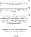
Fig.1 is a flowchart of a signal transmission method in some embodiments of the present disclosure; -
Fig.2 is a flowchart of a signal transmission method in some embodiments of the present disclosure; -
Fig.3 is a flowchart of a signal transmission method at a receiving apparatus side in some embodiments of the present disclosure; -
Fig.4 is a flowchart of a method at a sending apparatus side when applied to the CSI feedback; and -
Fig.5 is a flowchart of a method at a receiving apparatus side when applied to the CSI feedback. - The present disclosure will be described hereinafter in conjunction with the drawings. Although the embodiments of the present disclosure are shown in the drawings, it should be appreciated that the embodiments shall not be used to limit the scope of the present disclosure. Instead, the embodiments are used to make those skilled in the art to better understand the present disclosure and know the scope of the present disclosure.
- As shown in
Fig.1 , a signal transmission method is provided in some embodiments of the present disclosure, including: - Step 11: determining a codebook C, wherein the codebook C is a set of matrices W;
- Step 12: determining a matrix set Ω = {W} ∈ C from the codebook C;
The codebook is of a dual-stage codebook structure or a more-than-dual-stage codebook structure. - Step 13: generating one or more layers of signals, beamforming the signals with matrixes in the matrix set Ω, and cyclically mapping the matrixes in the matrix set Ω to different locations of transmission resources;
- Step 14: transmitting the beamformed signals at the different locations of the transmission resources.
- According to some embodiments of the present disclosure, a group of matrices which are enabled to be cyclically mapped to different transmission resources is determined, and the beamformed signals, which are obtained by beamforming one or more layers of signals through the matrices, are transmitted at different locations of the transmission resources, thereby improving the transmission performance of the transmission channel.
- As shown in
Fig.2 , a signal transmission method is provided in some embodiments of the present disclosure, including: - Step 21: determining a codebook C, wherein the codebook C is a set of matrices W.
- Step 22: determining a matrix set Ω = {W} ∈ C from the codebook C.
- The codebook is of a dual-stage codebook structure or a more-than-dual-stage codebook structure.
- Step 23: transmitting indication information of a determined group of matrices which are enabled to be cyclically mapped to different transmission resources.
- Specifically, the indication information of the determined group of matrices which are enabled to be cyclically mapped to the different transmission resources is transmitted by a semi-static signaling or a dynamic signaling, and this step is optional.
- Step 24: generating one or more layers of signals, beamforming the signals with matrixes in the matrix set Ω, and cyclically mapping the matrixes in the matrix set Ω to different locations of transmission resources.
- Step 25: transmitting the beamformed signals at the different locations of the transmission resources.
- According to some embodiments of the present disclosure, a group of matrices which are enabled to be cyclically mapped to different transmission resources is determined and then sent to the receiving apparatus, and the beamformed signals, which are obtained by beamforming one or more layers of signals through the matrices, are transmitted at different locations of the transmission resources, thereby improving the transmission performance of the transmission channel.
- In some embodiments of the present disclosure, each matrix W is generated by transforming a phase φ of at least one Discrete Fourier Transform DFT vector V.
- A set of DFT vectors corresponding to the matrices W in the matrix set Ω constitutes a group of adjacent DFT vectors V = {V 1,V 2,...VN }.
- A set of phases corresponding to the matrices W in the matrix set Ω constitutes a set of adjacent phases Θ = {φ 1,φ 2,...φK }.
- The DFT vectors corresponding to the matrices W mapped to adjacent transmission resources are discontinuous in V = {V 1,V 2,...VN }, or the phases φ corresponding to the matrices W mapped to adjacent transmission resources are discontinuous in Θ = {φ 1,φ 2,...φK }.
- Optionally, the codebook C is of a dual-stage codebook structure, and in the codebook C, the matrices W = W 1 W 2 = W 1 W 2 bW 2c ;
- Optionally, each W 1 matrix is formed by N DFT beams which are adjacent to each other and oriented at different angles, where N is a positive integer.
- A second-stage precoding matrix W 2b = {w 2b,1,...w 2b,L } is configured to perform a selection for beams in the W 1 , where w 2b,1,...w 2b,L are beam selection matrices, L is a positive integer. A cyclic mapping manner of the w 2b,l,...w 2b,L is: selecting, from the matrices in the W 1 , the matrices corresponding to the discontinuous DFT vectors for the adjacent transmission resources.
- A second-stage precoding matrix W 2c = {w 2c,k } k=1,2,... is configured to perform phase rotations for the beams in the W 1 , where w 2c,k is a phase transformation matrix.
- Optionally, the codebook C is of a dual-stage codebook structure, and in the codebook C, the matrices W = W 1 W 2 = W 1 W 2 bW 2c .
- Optionally, each W 1 matrix is formed by N DFT beams which are adjacent to each other and oriented at different angles, where N is a positive integer.
- A second-stage precoding matrix W 2b = {w 2b,1,...w 2b,L } is configured to perform a selection for the DFT vectors in the W 1 , where w 2b,1,...w 2b,L are beam selection matrices, L is a positive integer.
- A cyclic mapping manner of the w 2b,1,...w 2b,L is: selecting, from the matrices in the W 1, the matrices corresponding to the same or different DFT vectors for the adjacent transmission resources, where the selected DFT vectors are continuous or discontinuous when different DFT vectors are selected.
- A second-stage precoding matrix W 2c = {w 2c,k } k=1,2,... is configured to perform phase rotations for the beams in the W 1 , where w 2c,k is a phase transformation matrix, and a cyclic mapping manner of the w 2b,1,...w 2b,K is: selecting discontinuous phases from the second-stage precoding matrix W 2c = {w 2c,k } k=1,2,....
- In the above embodiments, Θ = {0,π/} or Θ = {π/2,3π/2}.
- Specifically, the first-stage precoding matrix W 1 = {w 1,k }, where

- For example, taking 4Tx/8Tx LTE codebook as an example, X 1,k = {V k,1,V k,2,...V k,N } represents a set of N precoding vectors when transmitting a layer of data, and each precoding vector corresponds to one beam.

- If w 1,k and w 1,k+1 have N/2 overlapping beams, and then the codebook W1 has


- For the second-stage precoding matrix W 2, when transmitting a layer of data, each w 2b,l consists of a set of column selection vectors {e 1,e 2,...eN }, where ei is the ith column of IN, 1≤l ≤L.
- When transmitting two layers of data,

- That is, {e 1, e 2, ... e N} means a continuous selection (or considered to be a continuous DFT beams) from the W1 matrix.
- For the second-stage precoding matrix W 2, when transmitting a layer of data, W 2c = {w 2c,1,...w 2c,M }, where w 2c,k = [1,ϕk ], ϕk = exp(j2π/M ∗(k-1)) where ϕk is the phase rotation vector used to combine beamforming angels at two polarization directions, j is a constant, where 1 ≤ k ≤ M. In the LTH codebook, in some scenarios ϕk = {0, 1/2, 1, 3/2}π.
- When transmitting two layers of data, W2 = {w 2c,k } k=1,2,..., which is

- When N=4, ϕk = {0, 1/2, 1, 3/2}π, the column selection matrix of W 2c may be one of the following matrices: {(e1 e1),(e2 e2),(e3 e3),(e4 e4)}, that is, the two layers of data use the same DFT beamforming vector, the phase rotation codebook W 2c = {w 2c,k } k=1,2,..., which may be written as

- The matrix in W 2c may also be in the form of (ei ej ), 1≤i≤N,1≤j≤N,i ≠ j, that is, the two layers of data select different DFT beams.
- In addition, in some embodiments, a degree of separation of the matrices mapped to two adjacent transmission resources is greater than a preset value.
- Specifically, the degree of separation of two matrices in the W 2b mapped to the two adjacent transmission resources is maximized based on a distance measurement value, the degree of separation of the two matrices in the W 2b is greater than a first preset value.
- The degree of separation of the two matrices in the W 2b is greater than the first preset value.
- The distance measurement value may be an Euclidean distance, or a Chebychev distance, or other possible distance measurement values.
- A distance between the phase transformation matrices w 2c,k in the W 2c mapped to the adjacent transmission resources is greater than a second preset value
Specifically, the precoding cycle in the present disclosure is not limited to the set {(e 1,e 1),(e 2,e 2),...(eN ,eN )}. - For rank-1, a cycle of the precoding based on the beam selection codebook W 2b = {w 2b,1,...w 2b,L } is designed to select a discontinuous or non-sequential DFT beams from the matrix of wl for the precoding of adjacent time/frequency resources.
- Specifically, in some embodiments of the present disclosure, the degree of separation of two matrices in the W 2b mapped to two adjacent time/frequency resources is maximized base on a single or multiplex distance measurement values.
- This distance measurement value may be an Euclidean distance, or a Chebychev distance, or other possible distance measurement values.
- The purpose of such mapping is to obtain a maximal diversity gain by maximizing the difference of the equivalent precoding channels of two adjacent time/frequency resources.
- This is because the wireless propagation channel is continuous, and the closer the two time/frequency resources are, the more relevant they are. The greater the degree of separation of the precoding matrices mapped to two adjacent time/frequency resources (i.e., the greater the distance is), the more possible the receiving apparatus eliminates the channel deep fading and the receive performance is more robust.
- In some embodiments of the present disclosure, assuming W 2b = {e1,e2,e3,e4}, the cycle of W is designed to map to adjacent time/frequency resources through the following W 2b matrix:
In some embodiments of the present disclosure, {el, e3, e2, e4} are mapped to four continuous time/frequency resources. - In some embodiments of the present disclosure, {el, e4, e2, e3} are mapped to four continuous time/frequency resources.
- Similarly, for rank-2, a cycle of the precoding based on the codebook W 2b = {w 2b,1,...w 2b,L } is designed to increase (or maximize) a distance of two precoding matrices mapped to adjacent time/frequency resources.
- In some embodiments of the present disclosure, W2b = {(e1,e1),(e2,e2),(e3,e3),(e4,e4)} The cycle of W is designed to map to four precoding matrices for the cycle of the corresponding W 2b = {(e1,e1),(e2,e2),(e3,e3),(e4,e4)} through the following manners.
- In some embodiments of the present disclosure, {(e1, e1), (e3, e3), (e2, e2), (e4, e4)} are mapped to four adjacent time/frequency resources.
- In some embodiments of the present disclosure, {(e1, e1), (e4, e4), (e2, e2), (e3, e3)} are mapped to four adjacent time/frequency resources.
- Accordingly, the set W 2c of co-phasing matrices may be represented as W 2c = {w 2c,1,...w 2c,M }.
- By the same token, the mapping of the co-phasing matrices in W 2c should ensure that the distance between the precoding matrices mapped to adjacent time/frequency resources is as large as possible.
- For rank-1, assuming W 2c = {w 2c,1,...w 2c,M }, where w 2c,m = [1,ϕm ], ϕm = exp(j2π/M ∗(m-1)).
- In some embodiments of the present disclosure, M=4, and ϕm = {0, 1, ½, 3/2} are mapped to adjacent time/frequency resources.
- For rank-2, W 2c = {w 2c,k } k=1,2,..., which is

- Some more detailed embodiments are provided below. Without loss of generality, the 8Tx (8-port) LTE dual-stage codebook structure is taken as an example.
- In some embodiments of the present disclosure, an LTE 8Tx is of a dual-stage codebook structure.
- For 8Tx, the codebook for rank-1 is:
i 1 i 2 0 1 2 3 4 5 6 7 0 - 15 


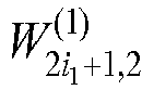

i 1 i 2 8 9 10 11 12 13 14 15 0 - 15 


where 
- The codebook for rank-2 is:
i 1 i 2 0 1 2 3 0 - 15 

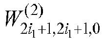

i 1 i 2 4 5 6 7 0 - 15 


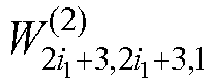
i 1 i 2 8 9 10 11 0 - 15 


i 1 i 2 12 13 14 15 0 - 15 


where 
- The numbers of W1 and W2 are denoted by i1 and i2, respectively.
- i2 = 0, 1, 2, 3 corresponds to the first beam of W1 (i.e., e1);
i2=4, 5, 6, 7 corresponds to the second beam of W1 (i.e., e2);
i2=8, 9, 10, 11 corresponds to the third beam of W1 (i.e., e3);
i2=12, 13, 14, 15 corresponds to the fourth beam of W1 (i.e., e4). - i2 = 0, 1 corresponds to the beam pair (e1, e1);
i2=2, 3 corresponds to the beam pair (e2, e2);
i2=4, 5 corresponds to the beam pair (e3, e3);
i2=6, 7 corresponds to the beam pair (e4, e4);
i2=8, 9 corresponds to the beam pair (e1, e2);
i2=10, 11 corresponds to the beam pair (e2, e3);
i2=12, 13 corresponds to the beam pair (e1, e4);
i2=14, 15 corresponds to the beam pair (e2, e4). - The method in the above embodiments is to maximize the distance of the cyclic precoding matrix.
- For rank-1, if the beam selection matrix (w2b) of the precoding matrix cycle uses the order of {el, e4, e2, e3}, co-phasing uses ϕm = {0, 1, ½, 3/2}pi, then the cycle of W2(i2) uses an order of {0, 2, 1, 3, 12, 14, 13, 15, 4, 6, 5, 7, 8, 10, 9, 11}, or
if the beam selection matrix (w2b) of the precoding matrix cycle uses the order of {el, e3, e2, e4}, co-phasing uses ϕm = {0, 1, ½, 3/2}pi, then the cycle of W2(i2) uses an order of {0, 2, 1, 3, 8, 10, 9, 11, 4, 6, 5, 7, 12, 14, 13, 15}. - For rank-2, it is assumed that the cycle is applied to the W2 matrix corresponding to (e1, e1), (e2, e2), (e3, e3), (e4, e4). If the cycle of W2 uses the order of {(e1, e1), (e4, e4), (e2, e2), (e3, e3)} for the beam selection, co-phasing uses ϕm = {0, 1} pi, and then the loop of W2(i2) uses an order of {0, 1, 6, 7, 2, 3, 4, 5}.
- According to some embodiments of the present disclosure, a group of matrices which are enabled to be cyclically mapped to different transmission resources is determined, and the beamformed signals, which are obtained by beamforming one or more layers of signals through the matrices, are transmitted at different locations of the transmission resources, thereby improving the transmission performance of the transmission channel.
- A signal transmission device is further provided in some embodiments of the present disclosure, including:
- a first determining module, configured to determine a codebook C, wherein the codebook C is a set of matrices W;
- a second determining module, configured to determine a matrix set Ω = {W} ∈ C from the codebook C; and
- a transmission module, configured to generate one or more layers of signals, beamform the signals with matrixes in the matrix set Ω, cyclically map the matrixes in the matrix set Ω to different locations of transmission resources, and transmit the beamformed signals at the different locations of the transmission resources;
- Optionally, each matrix W is generated by transforming a phase φ of at least one Discrete Fourier Transform DFT vector V;
a set of DFT vectors corresponding to the matrices W in the matrix set Ω constitutes a group of adjacent DFT vectors V = {V 1 ,V 2 ,...VN };
a set of phases corresponding to the matrices W in the matrix set Ω constitutes a set of adjacent phases Θ = {φ 1,φ 2,...φK };
the DFT vectors corresponding to the matrices Wmapped to adjacent transmission resources are discontinuous in V = {V 1 ,V 2,...VN }, or the phases φ corresponding to the matrices W mapped to adjacent transmission resources are discontinuous in Θ = {φ 1, φ 2,....φK }. - Optionally, the codebook C is of a dual-stage codebook structure, and in the codebook C, the matrices W = W 1 W 2 = W 1 W 2 bW 2c ;
Optionally, each W 1 matrix is formed by N DFT beams which are adjacent to each other and oriented at different angles, where N is a positive integer;
a second-stage precoding matrix W 2b = {w 2b,1,...w 2b,L } is configured to perform a selection for beams in the W 1 , where w 2b,l,...w 2b,L are beam selection matrices, L is a positive integer; a cyclic mapping manner of the w 2b,l,...w 2b,L is: selecting, from the matrices in the W 1 , the matrices corresponding to the discontinuous DFT vectors for the adjacent transmission resources;
a second-stage precoding matrix W 2c = {w 2c,k } k=1,2,... is configured to perform phase rotations for the beams in the W 1 , where w 2c,k is a phase transformation matrix. - Optionally, the codebook C is of a dual-stage codebook structure, and in the codebook C, the matrices W = W 1 W 2 = W 1 W 2 bW 2c ;
- Optionally, each W 1 matrix is formed by N DFT vectors which are adjacent to each other and oriented at different angles, where N is a positive integer;
a second-stage precoding matrix W 2b = {w 2b,l,...w 2b,L } is configured to perform a selection for the DFT vectors in the W 1 , where w 2b,l,...w 2b,L are beam selection matrices, L is a positive integer;
a cyclic mapping manner of the w 2b,l,...w 2b,L is: selecting, from the matrices in the W 1, the matrices corresponding to the same or different DFT vectors for the adjacent transmission resources, where the selected DFT vectors are continuous or discontinuous when different DFT vectors are selected;
a second-stage precoding matrix W 2c = {w 2ck } k=1,2... is configured to perform phase rotations for the beams in the W 1 , where w 2c,k is a phase transformation matrix, and a cyclic mapping manner of the w 2c,1,...w 2c,K is: selecting discontinuous phases from the second-stage precoding matrix W 2c = {w 2c,k } k=1,2,.... - Optionally, Θ = {0,π/} or Θ = {π/2,3π/2}.
- Optionally, a degree of separation of the matrices mapped to two adjacent transmission resources is greater than a preset value.
- Optionally, the degree of separation of two matrices in the W 2b mapped to the two adjacent transmission resources is maximized based on a distance measurement value, the degree of separation of the two matrices in the W 2b is greater than a first preset value.
- Optionally, a distance between the phase transformation matrices w 2c,k in the W 2c mapped to the adjacent transmission resources is greater than a second preset value.
- Optionally, the transmission module is further configured to transmit indication information of a determined group of matrices which are enabled to be cyclically mapped to different transmission resources.
- Optionally, the transmission module is further configured to transmit the indication information of the determined group of matrices which are enabled to be cyclically mapped to the different transmission resources by a semi-static signaling or a dynamic signaling.
- It should be noted that the device is a device corresponding to the above method, and all embodiments in the above method are applicable to the embodiments of the device, and the same technical effects may be achieved.
- A sending apparatus is further provided in some embodiments of the present disclosure, including: a processor, a memory connected to the processor through a bus interface, and a transceiver connected to the processor through a bus interface. The memory is used for storing the program and data used by the processor when performing the operation. The processor is configured to implement the following functional modules:
- a first determining module, configured to determine a codebook C, wherein the codebook C is a set of matrices W;
- a second determining module, configured to determine a matrix set Ω = {W} ∈ C from the codebook C; and
- a transmission module, configured to generate one or more layers of signals, beamform the signals with matrixes in the matrix set Ω, cyclically map the matrixes in the matrix set Ω to different locations of transmission resources, and transmit the beamformed signals at the different locations of the transmission resources.
- In the sending apparatus in some embodiments of the present disclosure, the bus interface may be an interface in a bus architecture, and the bus architecture may include any number of interconnected buses and bridges. To be specific, one or more processors represented by the processor and memory represented by the memory are linked together. The bus architecture may also link together various other circuits such as peripheral devices, voltage regulators and power management circuits. The bus interface provides interfaces. The processor is responsible for managing the bus architecture and the usual processing. The memory may store the data that processor uses when performing operations.
- The disclosed methods are applicable to the downlink (e.g., from the network to the mobile terminal) and the uplink (e.g., from the mobile terminal to the network). The "data" in the above statement may be any digital information bits including, but not limited to, user plane data and/or control plane data (carrying control information transmitted to or from a certain UE or group of UEs).
- As shown in
Fig.3 , a signal transmission method at a receiving apparatus side corresponding to the above method includes: - Step 31: acuiring a determined group of matrices which are enabled to be cyclically mapped to different transmission resources, where a matrix set Ω={W}∈C, a codebook C is a set of matrices W;
- Step 32: receiving beamformed signals transmitted at different locations of the transmission resources, where the beamformed signals are obtained by beamforming one or more layers of signals through the matrices.
- Optionally, each matrix W is generated by transforming a phase φ of at least one Discrete Fourier Transform DFT vector V;
a set of DFT vectors corresponding to the matrices W in the matrix set Ω constitutes a group of adjacent DFT vectors V = {V 1 ,V 2 ,...VN };
a set of phases corresponding to the matrices W in the matrix set Ω constitutes a set of adjacent phases Θ = {φ 1,φ 2,...φK };
the DFT vectors corresponding to the matrices Wmapped to adjacent transmission resources are discontinuous in V = {V 1 ,V 2,...VN }, or the phases φ corresponding to the matrices W mapped to adjacent transmission resources are discontinuous in Θ = {φ 1,φ 2....φK }. - Optionally, the codebook C is of a dual-stage codebook structure, and in the codebook C, the matrices W = W 1 W 2 = W 1 W 2 bW 2c .
- Optionally, each W 1 matrix is formed by N DFT beams which are adjacent to each other and oriented at different angles, where N is a positive integer;
a second-stage precoding matrix W 2b = {w 2b,1,...w 2b,L } is configured to perform a selection for beams in the W 1 , where w 2b,l,...w 2b,L are beam selection matrices, L is a positive integer; a cyclic mapping manner of the w 2b,1,...w 2b,L is: selecting, from the matrices in the W 1 , the matrices corresponding to the discontinuous DFT vectors for the adjacent transmission resources;
a second-stage precoding matrix W 2c = {w 2ck } k=1,2... is configured to perform phase rotations for the beams in the W 1 , where w 2c,k is a phase transformation matrix. - Optionally, the codebook C is of a dual-stage codebook structure, and in the codebook C, the matrices W = W 1 W 2 = W 1 W 2 bW 2c ;
Optionally, each W 1 matrix is formed by N DFT vectors which are adjacent to each other and oriented at different angles, where N is a positive integer;
a second-stage precoding matrix W 2b = {w 2b,l,...w 2b,L } is configured to perform a selection for the DFT vectors in the W 1 , where w 2b,l,...w 2b,L are beam selection matrices, L is a positive integer;
a cyclic mapping manner of the w 2b,l,...w 2b,L is: selecting, from the matrices in the W 1, the matrices corresponding to the same or different DFT vectors for the adjacent transmission resources, where the selected DFT vectors are continuous or discontinuous when different DFT vectors are selected;
a second-stage precoding matrix W 2c = {w 2ck } k=1,2... is configured to perform phase rotations for the beams in the W 1 , where w 2c,k is a phase transformation matrix, and a cyclic mapping manner of the w 2c,1 ...w 2c,K is: selecting discontinuous phases from the second-stage precoding matrix W 2c = {w 2c,k } k=1,2,.... - Furthermore, all the examples of the matrix in the foregoing method embodiments are applicable to the embodiment of the method of the receiving apparatus, and the same technical effects may be achieved.
- Corresponding to the method of the receiving apparatus, a signal transmission device is further provided in some embodiments of present disclosure, including:
- an acquisition module, configured to acquire a determined group of matrices which are enabled to be cyclically mapped to different transmission resources, where a matrix set Ω={W}∈C, a codebook C is a set of matrices W;
- a receiving module, configured to receive beamformed signals transmitted at different locations of the transmission resources, where the beamformed signals are obtained by beamforming one or more layers of signals through the matrices. It should be noted that all the examples of the precoding matrix in the foregoing method embodiments are applicable to the embodiment of the method of the receiving apparatus, and the same technical effects may be achieved.
- As shown in
Fig.4 , when applied to CSI feedback, the method at the sending apparatus side includes: - Step 41: determining, by a sending apparatus, a group of matrices which are enabled to be cyclically mapped to different transmission resources;
- Step 42: transmitting, by the sending apparatus, one or more layers of data coded by the matrices to a receiving apparatus;
- Step 43: indicating by the sending apparatus multiple precoding matrices to the receiving apparatus, which may be configured through a RRC signaling, and this step is optional;
- Step 44: receiving, by the sending apparatus, a feedback of channel state information CSI sent by the receiving apparatus, where the CSI includes indication information configured to indicate a selected precoding matrix. This method is also applicable to DMRS transmissions.
- A sending apparatus is further provided in some embodiments of the present disclosure, including:
- a determining module, configured to determine a group of matrices which are enabled to be cyclically mapped to different transmission resources;
- a transmitting module, configured to transmit one or more layers of data coded by the matrices to a receiving apparatus; and
- a receiving module, configured to receive a feedback of channel state information CSI sent by the receiving apparatus, where the CSI includes indication information configured to indicate a selected precoding matrix.
- As shown in
Fig.5 , when applied to CSI feedback, the method at the receiving apparatus side includes: - Step 51: receiving, by a receiving apparatus and through a RRC signaling, a plurality of precoding matrices being a group of precoding matrices which are enabled to be cyclically mapped to different transmission resources;
- Step 52: generating, by the receiving apparatus, channel state information CSI including indication information configured to indicate a selected matrix;
- Step 53: sending, by the receiving apparatus, the CSI to the sending apparatus.
- Again, this method is also applicable to DMRS transmissions.
- A receiving apparatus is further provided in some embodiments of the present disclosure, including:
- a receiving module, configured to receive a plurality of matrices being a group of matrices which are enabled to be cyclically mapped to different transmission resources;
- a feedback module, configured to generate channel state information CSI including indication information configured to indicate a selected matrix; and
- a sending module, configured to send the CSI to the sending apparatus.
- A receiving apparatus is further provided in some embodiments of the present disclosure, including:
a processor, a memory coupled to the processor via a bus interface, and a transceiver coupled to the processor via a bus interface, where the memory is configured to store programs and data used by the processor when performing operations, and the processor implements the following functions:
receiving an indication of the transmitter, where the indication carries a group of precoding matrices which are enabled to be cyclically mapped to different transmission resources; it should be noted that this step is optional; receiving one or more layers of data which may be coded by a group of precoding matrices which are enabled to be cyclically mapped to different transmission resources. - Here, the group of precoding matrices which are enabled to be cyclically mapped to different transmission resources may be mapped according to the methods described in some embodiments of the present disclosure.
- In the receiving apparatus in some embodiments of the present disclosure, the bus interface may be an interface in a bus architecture, and the bus architecture may include any number of interconnected buses and bridges. To be specific, one or more processors represented by the processor and memory represented by the memory are linked together. The bus architecture may also link together various other circuits such as peripheral devices, voltage regulators and power management circuits. The bus interface provides interfaces. The processor is responsible for managing the bus architecture and the usual processing. The memory may store the data that processor uses when performing operations.
- The sending apparatus in some embodiments of the present disclosure may be a base station, or may be a transmitter of the base station, and the receiving apparatus may be a terminal or a receiver of the terminal. Of course, the sending apparatus may also be a terminal or a transmitter of a terminal. The receiving apparatus may also be a base station or a receiver of a base station.
- The purpose of the design of the precoding matrix cycle under MIMO communication is to map non-contiguous/non-sequential beams on adjacent time/frequency resources. Specifically, a distance between precoding matrices mapped to adjacent time/frequency resources is maximized based on a particular distance measurement value and through non-continuous/non-sequential beams. In the non-ideal communication channel conditions, the robustness of the system is improved, so as to solve the attenuation of the channel amplitude.
- The present disclosure has been described with reference to the flow charts and/or block diagrams of the method, device (system) and computer program product according to the embodiments of the present disclosure. It should be understood that computer program instructions may be used to implement each of the work flows and/or blocks in the flow charts and/or the block diagrams, and the combination of the work flows and/or blocks in the flow charts and/or the block diagrams. These computer program instructions may be provided to a processor of a common computer, a dedicate computer, an embedded processor or any other programmable data processing devices to create a machine, so that instructions executable by the processor of the computer or the other programmable data processing devices may create a device to achieve the functions assigned in one or more work flows in the flow chart and/or one or more blocks in the block diagram.
- These computer program instructions may also be stored in a computer readable storage that may guide the computer or the other programmable data process devices to function in a certain way, so that the instructions stored in the computer readable storage may create a product including an instruction unit which achieves the functions assigned in one or more flows in the flow chart and/or one or more blocks in the block diagram.
- These computer program instructions may also be loaded in the computer or the other programmable data process devices, so that a series of operation steps are executed on the computer or the other programmable devices to create processes achieved by the computer. Therefore, the instructions executed in the computer or the other programmable devices provide the steps for achieving the function assigned in one or more flows in the flow chart and/or one or more blocks in the block diagram.
- The above are merely some embodiments of the present disclosure. A person skilled in the art may make further modifications and improvements without departing from the principle of the present disclosure, and these modifications and improvements shall also fall within the scope of the present disclosure.
Claims (34)
- A signal transmission method, comprising:determining a codebook C, wherein the codebook C is a set of matrices W;determining a matrix set Ω = {W} ∈ C from the codebook C;generating one or more layers of signals, beamforming the signals with matrixes in the matrix set Ω, and cyclically mapping the matrixes in the matrix set Ω to different locations of transmission resources; andtransmitting the beamformed signals at the different locations of the transmission resources.
- The method according to claim 1, wherein each matrix W is generated by transforming a phase φ of at least one Discrete Fourier Transform DFT vector V;
a set of DFT vectors corresponding to the matrices W in the matrix set Ω constitutes a group of adjacent DFT vectors V = {V 1,V 2,...VN };
a set of phases corresponding to the matrices W in the matrix set Ω constitutes a set of adjacent phases Θ = {φ 1,φ 2,...φK };
the DFT vectors corresponding to the matrices W mapped to adjacent transmission resources are discontinuous in V = {V 1,V 2,...VN }, or the phases φ corresponding to the matrices W mapped to adjacent transmission resources are discontinuous in Θ = {φ 1,φ 2,...φK }. - The method according to claim 2, wherein the codebook C is of a dual-stage codebook structure, and in the codebook C, the matrices W = W 1 W 2 = W 1 W 2 bW 2c ;
wherein each W 1 matrix is formed by N DFT beams which are adjacent to each other and oriented at different angles, wherein N is a positive integer;
a second-stage precoding matrix W 2b = {w 2b,1,...w 2b,L } is configured to perform a selection for beams in the W 1 , wherein w 2b,1,...w 2b,L are beam selection matrices, L is a positive integer;
a cyclic mapping manner of the w 2b,1,...w 2b,L is: selecting, from the matrices in the W 1 , the matrices corresponding to the discontinuous DFT vectors for the adjacent transmission resources;
a second-stage precoding matrix W 2c = {w 2c,k } k=1,2,... is configured to perform phase rotations for the beams in the W 1, wherein w 2c,k is a phase transformation matrix. - The method according to claim 2, wherein the codebook C is of a dual-stage codebook structure, and in the codebook C, the matrices W = W 1 W 2 = W 1 W 2 bW 2c ;
wherein each W 1 matrix is formed by N DFT vectors which are adjacent to each other and oriented at different angles, wherein N is a positive integer;
a second-stage precoding matrix W 2b = {w 2b,1,...w 2b,L } is configured to perform a selection for the DFT vectors in the W 1 , wherein w 2b,1,...w 2b,L are beam selection matrices, L is a positive integer;
a cyclic mapping manner of the w 2b,1,...w 2b,L is: selecting, from the matrices in the W 1 , the matrices corresponding to the same or different DFT vectors for the adjacent transmission resources, wherein the selected DFT vectors are continuous or discontinuous when different DFT vectors are selected;
a second-stage precoding matrix W 2c = {w 2c,k } k=1,2,... is configured to perform phase rotations for the beams in the W 1 , wherein w 2c,k is a phase transformation matrix, and a cyclic mapping manner of the w 2c,1,...w 2c,K is: selecting discontinuous phases from the second-stage precoding matrix W 2c = {w 2c,k } k=1,2,.... - The method according to claim 2, wherein Θ = {0, π /} or Θ = {π/2,3π/2}.
- The method according to claim 3 or 4, wherein a degree of separation of the matrices mapped to two adjacent transmission resources is greater than a preset value.
- The method according to claim 6, wherein the degree of separation of two matrices in the W 2b mapped to the two adjacent transmission resources is maximized based on a distance measurement value, the degree of separation of the two matrices in the W 2b is greater than a first preset value.
- The method according to claim 3 or 4, wherein a distance between the phase transformation matrices w 2c,k in the W 2c mapped to the adjacent transmission resources is greater than a second preset value.
- The method according to claim 1, further comprising: transmitting indication information of a determined group of matrices which are enabled to be cyclically mapped to different transmission resources.
- The method according to claim 9, wherein the transmitting the indication information of the determined group of matrices which are enabled to be cyclically mapped to the different transmission resources comprises:
transmitting the indication information of the determined group of matrices which are enabled to be cyclically mapped to the different transmission resources by a semi-static signaling or a dynamic signaling. - A signal transmission device, comprising:a first determining module, configured to determine a codebook C, wherein the codebook C is a set of matrices W;a second determining module, configured to determine a matrix set Ω = {W} ∈ C from the codebook C; anda transmission module, configured to generate one or more layers of signals, beamform the signals with matrixes in the matrix set Ω, cyclically map the matrixes in the matrix set Ω to different locations of transmission resources, and transmit the beamformed signals at the different locations of the transmission resources.
- The device according to claim 11, wherein each matrix W is generated by transforming a phase φ of at least one Discrete Fourier Transform DFT vector V;
a set of DFT vectors corresponding to the matrices W in the matrix set Ω constitutes a group of adjacent DFT vectors V = {V 1,V 2,...VN };
a set of phases corresponding to the matrices W in the matrix set Ω constitutes a set of adjacent phases Θ = {φ 1,φ 2,...φK };
the DFT vectors corresponding to the matrices W mapped to adjacent transmission resources are discontinuous in V = {V 1,V 2,...VN }, or the phases φ corresponding to the matrices W mapped to adjacent transmission resources are discontinuous in Θ = {φ 1,φ 2,...φK }. - The device according to claim 12, wherein the codebook C is of a dual-stage codebook structure, and in the codebook C, the matrices W = W 1 W 2 = W 1 W 2 bW 2c ;
wherein each W 1 matrix is formed by N DFT beams which are adjacent to each other and oriented at different angles, wherein N is a positive integer;
a second-stage precoding matrix W 2b = {w 2b,1,...w 2b,L } is configured to perform a selection for beams in the W 1 , wherein w 2b,1,...w 2b,L are beam selection matrices, L is a positive integer;
a cyclic mapping manner of the w 2b,1,...w 2b,L is: selecting, from the matrices in the W 1 , the matrices corresponding to the discontinuous DFT vectors for the adjacent transmission resources;
a second-stage precoding matrix W 2c = {w 2c,k } k=1,2,... is configured to perform phase rotations for the beams in the W 1 , wherein w 2c,k is a phase transformation matrix. - The device according to claim 12, wherein the codebook C is of a dual-stage codebook structure, and in the codebook C, the matrices W = W 1 W 2 = W 1 W 2 bW 2c ;
wherein each W 1 matrix is formed by N DFT vectors which are adjacent to each other and oriented at different angles, wherein N is a positive integer;
a second-stage precoding matrix W 2b = {w 2b,1,...w 2b,L } is configured to perform a selection for the DFT vectors in the W 1 , wherein w 2b,1,...w 2b,L are beam selection matrices, L is a positive integer;
a cyclic mapping manner of the w 2b,1,...w 2b,L is: selecting, from the matrices in the W 1 , the matrices corresponding to the same or different DFT vectors for the adjacent transmission resources, wherein the selected DFT vectors are continuous or discontinuous when different DFT vectors are selected;
a second-stage precoding matrix W 2c = {w 2c,k } k=1,2,... is configured to perform phase rotations for the beams in the W 1 , wherein w 2c,k is a phase transformation matrix, and a cyclic mapping manner of the w 2c,1,...w 2c,K is: selecting discontinuous phases from the second-stage precoding matrix W 2c = {w 2c,k } k=1,2,.... - The device according to claim 12, wherein Θ = {0,π/} or Θ = {π/2,3π/2}.
- The device according to claim 13 or 14, wherein a degree of separation of the matrices mapped to two adjacent transmission resources is greater than a preset value.
- The device according to claim 16, wherein the degree of separation of two matrices in the W 2b mapped to the two adjacent transmission resources is maximized based on a distance measurement value, the degree of separation of the two matrices in the W 2b is greater than a first preset value.
- The device according to claim 13 or 14, wherein a distance between the phase transformation matrices w 2c,k in the W 2c mapped to the adjacent transmission resources is greater than a second preset value.
- The device according to claim 11, wherein the transmission module is further configured to transmit indication information of a determined group of matrices which are enabled to be cyclically mapped to different transmission resources.
- The device according to claim 19, wherein the transmission module is further configured to transmit the indication information of the determined group of matrices which are enabled to be cyclically mapped to the different transmission resources by a semi-static signaling or a dynamic signaling.
- A signal transmission method, comprising:acquiring a determined group of matrices which are enabled to be cyclically mapped to different transmission resources, wherein a matrix set Ω={W}∈C, a codebook C is a set of matrices W;receiving beamformed signals transmitted at different locations of the transmission resources, wherein the beamformed signals are obtained by beamforming one or more layers of signals through the matrices.
- The method according to claim 21, wherein each matrix W is generated by transforming a phase φ of at least one Discrete Fourier Transform DFT vector V;
a set of DFT vectors corresponding to the matrices W in the matrix set Ω constitutes a group of adjacent DFT vectors V = {V 1,V 2,...VN };
a set of phases corresponding to the matrices W in the matrix set Ω constitutes a set of adjacent phases Θ = {φ 1,φ 2,...φK };
the DFT vectors corresponding to the matrices W mapped to adjacent transmission resources are discontinuous in V = {V 1,V 2,...VN }, or the phases φ corresponding to the matrices W mapped to adjacent transmission resources are discontinuous in Θ = {φ 1,φ 2,...φK }. - The method according to claim 22, wherein the codebook C is of a dual-stage codebook structure, and in the codebook C, the matrices W = W 1 W 2 = W 1 W 2 bW 2c ;
wherein each W 1 matrix is formed by N DFT beams which are adjacent to each other and oriented at different angles, wherein N is a positive integer;
a second-stage precoding matrix W 2b = {w 2b,1,...w 2b,L } is configured to perform a selection for beams in the W 1 , wherein w 2b,1,...w 2b,L are beam selection matrices, L is a positive integer;
a cyclic mapping manner of the w 2b,1,...w 2b,L is: selecting, from the matrices in the W 1 , the matrices corresponding to the discontinuous DFT vectors for the adjacent transmission resources;
a second-stage precoding matrix W 2c = {w 2ck } k=1,2... is configured to perform phase rotations for the beams in the W 1 , wherein w 2c,k is a phase transformation matrix. - The method according to claim 22, wherein the codebook C is of a dual-stage codebook structure, and in the codebook C, the matrices W = W 1 W 2 = W 1 W 2 bW 2c ;
wherein each W 1 matrix is formed by N DFT vectors which are adjacent to each other and oriented at different angles, wherein N is a positive integer;
a second-stage precoding matrix W 2b = {w 2b,1,...w 2b,L } is configured to perform a selection for the DFT vectors in the W 1 , wherein w 2b,1,...w 2b,L are beam selection matrices, L is a positive integer;
a cyclic mapping manner of the w 2b,1,...w 2b,L is: selecting, from the matrices in the W 1 , the matrices corresponding to the same or different DFT vectors for the adjacent transmission resources, wherein the selected DFT vectors are continuous or discontinuous when different DFT vectors are selected;
a second-stage precoding matrix W 2c = {w 2c,k } k=1,2,... is configured to perform phase rotations for the beams in the W 1 , wherein w 2c,k is a phase transformation matrix, and a cyclic mapping manner of the w 2c,1,...w 2c,K is: selecting discontinuous phases from the second-stage precoding matrix W 2c = {W 2c,k } k=1,2,... . - A signal transmission device, comprising:an acquisition module, configured to acquire a determined group of matrices which are enabled to be cyclically mapped to different transmission resources, wherein a matrix set Ω={W}∈C, a codebook C is a set of matrices W;a receiving module, configured to receive beamformed signals transmitted at different locations of the transmission resources, wherein the beamformed signals are obtained by beamforming one or more layers of signals through the matrices.
- An uplink channel feedback method, comprising:determining, by a sending apparatus, a group of matrices which are enabled to be cyclically mapped to different transmission resources;transmitting, by the sending apparatus, one or more layers of data coded by the matrices to a receiving apparatus;receiving, by the sending apparatus, a feedback of channel state information CSI sent by the receiving apparatus, wherein the CSI comprises indication information configured to indicate a selected precoding matrix.
- The method according to claim 26, further comprising: indicating, by the sending apparatus, a plurality of matrices to the receiving apparatus.
- A sending apparatus, comprising:a determining module, configured to determine a group of matrices which are enabled to be cyclically mapped to different transmission resources;a transmitting module, configured to transmit one or more layers of data coded by the matrices to a receiving apparatus; anda receiving module, configured to receive a feedback of channel state information CSI sent by the receiving apparatus, wherein the CSI comprises indication information configured to indicate a selected precoding matrix.
- A uplink channel feedback method, comprising:receiving, by a receiving apparatus, a plurality of matrices being a group of matrices which are enabled to be cyclically mapped to different transmission resources;generating, by the receiving apparatus, channel state information CSI comprising indication information configured to indicate a selected matrix; andsending, by the receiving apparatus, the CSI to the sending apparatus.
- A receiving apparatus, comprising:a receiving module, configured to receive a plurality of matrices being a group of matrices which are enabled to be cyclically mapped to different transmission resources;a feedback module, configured to generate channel state information CSI comprising indication information configured to indicate a selected matrix; anda sending module, configured to send the CSI to the sending apparatus.
- A signal transmission device, comprising a processor, a transceiver and a memory, wherein the processor is configured to read a program in the memory to:determine a codebook C, wherein the codebook C is a set of matrices W;determine a matrix set Ω = {W} ∈ C from the codebook C; andgenerate one or more layers of signals, beamform the signals with matrixes in the matrix set Ω, cyclically map the matrixes in the matrix set Ω to different locations of transmission resources and transmit the beamformed signals at the different locations of the transmission resources;the transceiver is configured to receive and transmit data; andthe memory is configured to store data used by the processor when performing an operation.
- A signal transmission device, comprising a processor, a transceiver and a memory, wherein the processor is configured to read a program in the memory to:acquire a determined group of matrices which are enabled to be cyclically mapped to different transmission resources, wherein a matrix set Ω={W}∈C, a codebook C is a set of matrices W; andreceive beamformed signals transmitted at different locations of the transmission resources, wherein the beamformed signals are obtained by beamforming one or more layers of signals through the matrices;the transceiver is configured to receive and transmit data; andthe memory is configured to store data used by the processor when performing an operation.
- A sending apparatus, comprising a processor, a transceiver and a memory, wherein the processor is configured to read a program in the memory to:determine a group of matrices which are enabled to be cyclically mapped to different transmission resources;transmit one or more layers of data coded by the matrices to a receiving apparatus; andreceive a feedback of channel state information CSI sent by the receiving apparatus, wherein the CSI comprises indication information configured to indicate a selected precoding matrix;the transceiver is configured to receive and transmit data; andthe memory is configured to store data used by the processor when performing an operation.
- A receiving apparatus, comprising a processor, a transceiver and a memory, wherein the processor is configured to read a program in the memory to:receive a plurality of matrices being a group of matrices which are enabled to be cyclically mapped to different transmission resources;generate channel state information CSI comprising indication information configured to indicate a selected matrix; andsend the CSI to the sending apparatus;the transceiver is configured to receive and transmit data; andthe memory is configured to store data used by the processor when performing an operation.
Priority Applications (1)
| Application Number | Priority Date | Filing Date | Title |
|---|---|---|---|
| EP25188900.2A EP4607829A3 (en) | 2016-09-22 | 2017-09-12 | Method and device for signal transmission |
Applications Claiming Priority (2)
| Application Number | Priority Date | Filing Date | Title |
|---|---|---|---|
| CN201610842889.7A CN107863999B (en) | 2016-09-22 | 2016-09-22 | Signal transmission method and device |
| PCT/CN2017/101367 WO2018054242A1 (en) | 2016-09-22 | 2017-09-12 | Method and device for signal transmission |
Related Child Applications (2)
| Application Number | Title | Priority Date | Filing Date |
|---|---|---|---|
| EP25188900.2A Division-Into EP4607829A3 (en) | 2016-09-22 | 2017-09-12 | Method and device for signal transmission |
| EP25188900.2A Division EP4607829A3 (en) | 2016-09-22 | 2017-09-12 | Method and device for signal transmission |
Publications (4)
| Publication Number | Publication Date |
|---|---|
| EP3518431A1 true EP3518431A1 (en) | 2019-07-31 |
| EP3518431A4 EP3518431A4 (en) | 2019-10-09 |
| EP3518431C0 EP3518431C0 (en) | 2025-08-20 |
| EP3518431B1 EP3518431B1 (en) | 2025-08-20 |
Family
ID=61690183
Family Applications (2)
| Application Number | Title | Priority Date | Filing Date |
|---|---|---|---|
| EP17852310.6A Active EP3518431B1 (en) | 2016-09-22 | 2017-09-12 | Method and device for signal transmission |
| EP25188900.2A Pending EP4607829A3 (en) | 2016-09-22 | 2017-09-12 | Method and device for signal transmission |
Family Applications After (1)
| Application Number | Title | Priority Date | Filing Date |
|---|---|---|---|
| EP25188900.2A Pending EP4607829A3 (en) | 2016-09-22 | 2017-09-12 | Method and device for signal transmission |
Country Status (4)
| Country | Link |
|---|---|
| US (1) | US10911112B2 (en) |
| EP (2) | EP3518431B1 (en) |
| CN (1) | CN107863999B (en) |
| WO (1) | WO2018054242A1 (en) |
Family Cites Families (19)
| Publication number | Priority date | Publication date | Assignee | Title |
|---|---|---|---|---|
| WO2008058112A2 (en) * | 2006-11-06 | 2008-05-15 | Qualcomm Incorporated | Mimo transmission with layer permutation in a wireless communication system |
| KR101179627B1 (en) * | 2008-12-22 | 2012-09-04 | 한국전자통신연구원 | Method And Apparatus For Allocating Demodulation Reference Signal |
| WO2010105415A1 (en) * | 2009-03-17 | 2010-09-23 | Huawei Technologies Co., Ltd. | Method for generating a codebook |
| KR101653022B1 (en) * | 2009-05-29 | 2016-08-31 | 파나소닉 인텔렉츄얼 프로퍼티 코포레이션 오브 아메리카 | Terminal apparatus, base station apparatus, transmission method, receiving method, and integrated circuit |
| KR101276855B1 (en) * | 2010-03-08 | 2013-06-18 | 엘지전자 주식회사 | A method and a user equipment for transmitting precoding matrix information, and a method and a base station for configuring a precoding matrix |
| US9559884B2 (en) * | 2011-02-07 | 2017-01-31 | Intel Corporation | Co-phasing of transmissions from multiple infrastructure nodes |
| CN103782522B (en) * | 2011-03-31 | 2017-02-01 | 华为技术有限公司 | Method in a wireless communication system |
| CN102315872B (en) | 2011-08-18 | 2014-01-15 | 北京理工大学 | Transmission method of non-codebook pre-coding in long term evolution-advanced (LTE-A) system |
| CN103001742B (en) * | 2011-09-09 | 2018-12-07 | 中兴通讯股份有限公司 | Open loop MIMO transmission method and device based on demodulated reference signal |
| CN103475397B (en) | 2012-06-08 | 2018-03-23 | 中兴通讯股份有限公司 | A kind of method, communication station and the movement station of three-dimensional wave beam forming |
| US9136930B2 (en) * | 2012-07-16 | 2015-09-15 | Lg Electronics Inc. | Method and device for feeding back channel information in wireless communication system supporting multi-input multi-output scheme |
| WO2014101242A1 (en) * | 2012-12-31 | 2014-07-03 | 华为技术有限公司 | Method for reporting channel state information (csi), user equipment and base station |
| CN103929266B (en) * | 2013-01-15 | 2019-08-09 | 中兴通讯股份有限公司 | Control channel transmission, transmission processing method and device, network side equipment, terminal |
| US9281881B2 (en) * | 2013-02-12 | 2016-03-08 | Texas Instruments Incorporated | 4TX codebook enhancement in LTE |
| CN103220024B (en) * | 2013-04-18 | 2018-06-08 | 电子科技大学 | A kind of multi-user matches the beam form-endowing method of virtual MIMO system |
| EP3086483B1 (en) * | 2014-01-09 | 2019-04-10 | Huawei Technologies Co., Ltd. | Pre-coding matrix set determination method, parameter indication information sending method and apparatus |
| CN111641485B (en) * | 2014-09-25 | 2023-06-02 | 株式会社Ntt都科摩 | User device and transmission method |
| WO2016183737A1 (en) * | 2015-05-15 | 2016-11-24 | Qualcomm Incorporated | Enhanced csi procedures for fd-mimo |
| EP3327944A4 (en) * | 2015-07-23 | 2019-03-20 | LG Electronics Inc. | METHOD FOR TRANSMITTING AND RECEIVING A SIGNAL BASED ON A CODEBOOK IN A MULTI-ANTENNA WIRELESS COMMUNICATION SYSTEM AND APPARATUS THEREFOR |
-
2016
- 2016-09-22 CN CN201610842889.7A patent/CN107863999B/en active Active
-
2017
- 2017-09-12 EP EP17852310.6A patent/EP3518431B1/en active Active
- 2017-09-12 EP EP25188900.2A patent/EP4607829A3/en active Pending
- 2017-09-12 WO PCT/CN2017/101367 patent/WO2018054242A1/en not_active Ceased
- 2017-09-12 US US16/335,660 patent/US10911112B2/en active Active
Also Published As
| Publication number | Publication date |
|---|---|
| US10911112B2 (en) | 2021-02-02 |
| EP3518431A4 (en) | 2019-10-09 |
| EP3518431C0 (en) | 2025-08-20 |
| EP3518431B1 (en) | 2025-08-20 |
| WO2018054242A1 (en) | 2018-03-29 |
| CN107863999A (en) | 2018-03-30 |
| EP4607829A3 (en) | 2026-03-04 |
| US20200028553A1 (en) | 2020-01-23 |
| EP4607829A2 (en) | 2025-08-27 |
| CN107863999B (en) | 2021-01-22 |
Similar Documents
| Publication | Publication Date | Title |
|---|---|---|
| EP3427405B1 (en) | Method and apparatus for explicit csi reporting in advanced wireless communication systems | |
| US10447360B2 (en) | Massive digital-analog hybrid antenna, channel state information feedback method and channel state information feedback device | |
| US10868600B2 (en) | Method for reporting and receiving channel state information, and device | |
| EP3522677A1 (en) | Method and device for transmitting channel state information | |
| EP3910815A1 (en) | Method and apparatus for codebook design and signaling | |
| EP3343777A1 (en) | Methods and apparatuses for transmitting coding indication information and determining precoding matrix | |
| EP2925042A1 (en) | Method, system, and device for transmitting preamble signal and for signal measurement | |
| EP2913950A1 (en) | Method, system, and device for transmitting coding instruction information and for determining pre-coding matrix | |
| EP2911330B1 (en) | Method, system, and device for transmitting coding instruction information and for determining pre-coding matrix | |
| EP2963841B1 (en) | Data transmission method and device of multi-aerial system | |
| EP3367583B1 (en) | Methods and apparatuses for transmitting and receiving channel state information | |
| EP3429090B1 (en) | Method and device for transmitting feedback information | |
| EP3007380A1 (en) | Method and device for determining precoding matrix indicator, user equipment, and base station | |
| EP2913949B1 (en) | Method, system and device for transmitting pre-coded indication information and determining pre-coding matrix | |
| CN106487435A (en) | A kind of transmission coding indication information and the method and apparatus for determining pre-coding matrix | |
| EP2965481B1 (en) | Multiple transmitter codebook methods and devices | |
| CN103795450A (en) | Methods for transmitting coding indication information and determining pre-coding matrix, system and equipment | |
| US10205500B2 (en) | Data transmission method and data transmisiion device | |
| KR101783589B1 (en) | Codebook, and method and device for generating precoder based on same | |
| EP3518431B1 (en) | Method and device for signal transmission |
Legal Events
| Date | Code | Title | Description |
|---|---|---|---|
| STAA | Information on the status of an ep patent application or granted ep patent |
Free format text: STATUS: THE INTERNATIONAL PUBLICATION HAS BEEN MADE |
|
| PUAI | Public reference made under article 153(3) epc to a published international application that has entered the european phase |
Free format text: ORIGINAL CODE: 0009012 |
|
| STAA | Information on the status of an ep patent application or granted ep patent |
Free format text: STATUS: REQUEST FOR EXAMINATION WAS MADE |
|
| 17P | Request for examination filed |
Effective date: 20190418 |
|
| AK | Designated contracting states |
Kind code of ref document: A1 Designated state(s): AL AT BE BG CH CY CZ DE DK EE ES FI FR GB GR HR HU IE IS IT LI LT LU LV MC MK MT NL NO PL PT RO RS SE SI SK SM TR |
|
| AX | Request for extension of the european patent |
Extension state: BA ME |
|
| A4 | Supplementary search report drawn up and despatched |
Effective date: 20190906 |
|
| RIC1 | Information provided on ipc code assigned before grant |
Ipc: H04B 7/06 20060101ALN20190902BHEP Ipc: H04B 7/0456 20170101AFI20190902BHEP |
|
| DAV | Request for validation of the european patent (deleted) | ||
| DAX | Request for extension of the european patent (deleted) | ||
| RAP1 | Party data changed (applicant data changed or rights of an application transferred) |
Owner name: DATANG MOBILE COMMUNICATIONS EQUIPMENT CO., LTD. |
|
| STAA | Information on the status of an ep patent application or granted ep patent |
Free format text: STATUS: EXAMINATION IS IN PROGRESS |
|
| 17Q | First examination report despatched |
Effective date: 20211122 |
|
| GRAP | Despatch of communication of intention to grant a patent |
Free format text: ORIGINAL CODE: EPIDOSNIGR1 |
|
| STAA | Information on the status of an ep patent application or granted ep patent |
Free format text: STATUS: GRANT OF PATENT IS INTENDED |
|
| RIC1 | Information provided on ipc code assigned before grant |
Ipc: H04L 1/00 20060101ALN20250227BHEP Ipc: H04B 7/0456 20170101AFI20250227BHEP |
|
| INTG | Intention to grant announced |
Effective date: 20250313 |
|
| GRAS | Grant fee paid |
Free format text: ORIGINAL CODE: EPIDOSNIGR3 |
|
| GRAA | (expected) grant |
Free format text: ORIGINAL CODE: 0009210 |
|
| STAA | Information on the status of an ep patent application or granted ep patent |
Free format text: STATUS: THE PATENT HAS BEEN GRANTED |
|
| AK | Designated contracting states |
Kind code of ref document: B1 Designated state(s): AL AT BE BG CH CY CZ DE DK EE ES FI FR GB GR HR HU IE IS IT LI LT LU LV MC MK MT NL NO PL PT RO RS SE SI SK SM TR |
|
| REG | Reference to a national code |
Ref country code: GB Ref legal event code: FG4D |
|
| REG | Reference to a national code |
Ref country code: CH Ref legal event code: EP |
|
| REG | Reference to a national code |
Ref country code: DE Ref legal event code: R096 Ref document number: 602017091362 Country of ref document: DE |
|
| REG | Reference to a national code |
Ref country code: IE Ref legal event code: FG4D |
|
| PGFP | Annual fee paid to national office [announced via postgrant information from national office to epo] |
Ref country code: GB Payment date: 20250919 Year of fee payment: 9 |
|
| U01 | Request for unitary effect filed |
Effective date: 20250912 |
|
| U07 | Unitary effect registered |
Designated state(s): AT BE BG DE DK EE FI FR IT LT LU LV MT NL PT RO SE SI Effective date: 20250919 |
|
| U20 | Renewal fee for the european patent with unitary effect paid |
Year of fee payment: 9 Effective date: 20251028 |
|
| PG25 | Lapsed in a contracting state [announced via postgrant information from national office to epo] |
Ref country code: IS Free format text: LAPSE BECAUSE OF FAILURE TO SUBMIT A TRANSLATION OF THE DESCRIPTION OR TO PAY THE FEE WITHIN THE PRESCRIBED TIME-LIMIT Effective date: 20251220 |
|
| PG25 | Lapsed in a contracting state [announced via postgrant information from national office to epo] |
Ref country code: NO Free format text: LAPSE BECAUSE OF FAILURE TO SUBMIT A TRANSLATION OF THE DESCRIPTION OR TO PAY THE FEE WITHIN THE PRESCRIBED TIME-LIMIT Effective date: 20251120 |
|
| PG25 | Lapsed in a contracting state [announced via postgrant information from national office to epo] |
Ref country code: HR Free format text: LAPSE BECAUSE OF FAILURE TO SUBMIT A TRANSLATION OF THE DESCRIPTION OR TO PAY THE FEE WITHIN THE PRESCRIBED TIME-LIMIT Effective date: 20250820 |
|
| PG25 | Lapsed in a contracting state [announced via postgrant information from national office to epo] |
Ref country code: GR Free format text: LAPSE BECAUSE OF FAILURE TO SUBMIT A TRANSLATION OF THE DESCRIPTION OR TO PAY THE FEE WITHIN THE PRESCRIBED TIME-LIMIT Effective date: 20251121 |
|
| PG25 | Lapsed in a contracting state [announced via postgrant information from national office to epo] |
Ref country code: PL Free format text: LAPSE BECAUSE OF FAILURE TO SUBMIT A TRANSLATION OF THE DESCRIPTION OR TO PAY THE FEE WITHIN THE PRESCRIBED TIME-LIMIT Effective date: 20250820 |
|
| PG25 | Lapsed in a contracting state [announced via postgrant information from national office to epo] |
Ref country code: RS Free format text: LAPSE BECAUSE OF FAILURE TO SUBMIT A TRANSLATION OF THE DESCRIPTION OR TO PAY THE FEE WITHIN THE PRESCRIBED TIME-LIMIT Effective date: 20251120 |
|
| PG25 | Lapsed in a contracting state [announced via postgrant information from national office to epo] |
Ref country code: ES Free format text: LAPSE BECAUSE OF FAILURE TO SUBMIT A TRANSLATION OF THE DESCRIPTION OR TO PAY THE FEE WITHIN THE PRESCRIBED TIME-LIMIT Effective date: 20250820 |
|
| PG25 | Lapsed in a contracting state [announced via postgrant information from national office to epo] |
Ref country code: SM Free format text: LAPSE BECAUSE OF FAILURE TO SUBMIT A TRANSLATION OF THE DESCRIPTION OR TO PAY THE FEE WITHIN THE PRESCRIBED TIME-LIMIT Effective date: 20250820 |
|
| PG25 | Lapsed in a contracting state [announced via postgrant information from national office to epo] |
Ref country code: CZ Free format text: LAPSE BECAUSE OF FAILURE TO SUBMIT A TRANSLATION OF THE DESCRIPTION OR TO PAY THE FEE WITHIN THE PRESCRIBED TIME-LIMIT Effective date: 20250820 |
|
| PG25 | Lapsed in a contracting state [announced via postgrant information from national office to epo] |
Ref country code: SK Free format text: LAPSE BECAUSE OF FAILURE TO SUBMIT A TRANSLATION OF THE DESCRIPTION OR TO PAY THE FEE WITHIN THE PRESCRIBED TIME-LIMIT Effective date: 20250820 |
|
| REG | Reference to a national code |
Ref country code: CH Ref legal event code: H13 Free format text: ST27 STATUS EVENT CODE: U-0-0-H10-H13 (AS PROVIDED BY THE NATIONAL OFFICE) Effective date: 20260504 |
|
| PLBE | No opposition filed within time limit |
Free format text: ORIGINAL CODE: 0009261 |
|
| STAA | Information on the status of an ep patent application or granted ep patent |
Free format text: STATUS: NO OPPOSITION FILED WITHIN TIME LIMIT |
|
| PG25 | Lapsed in a contracting state [announced via postgrant information from national office to epo] |
Ref country code: MC Free format text: LAPSE BECAUSE OF FAILURE TO SUBMIT A TRANSLATION OF THE DESCRIPTION OR TO PAY THE FEE WITHIN THE PRESCRIBED TIME-LIMIT Effective date: 20250820 |
|
| REG | Reference to a national code |
Ref country code: CH Ref legal event code: L10 Free format text: ST27 STATUS EVENT CODE: U-0-0-L10-L00 (AS PROVIDED BY THE NATIONAL OFFICE) Effective date: 20260701 |
|
| PG25 | Lapsed in a contracting state [announced via postgrant information from national office to epo] |
Ref country code: IE Free format text: LAPSE BECAUSE OF NON-PAYMENT OF DUE FEES Effective date: 20250912 Ref country code: CH Free format text: LAPSE BECAUSE OF NON-PAYMENT OF DUE FEES Effective date: 20250930 |
|
| 26N | No opposition filed |
Effective date: 20260521 |