EP3518320A1 - Battery pack - Google Patents
Battery pack Download PDFInfo
- Publication number
- EP3518320A1 EP3518320A1 EP16916831.7A EP16916831A EP3518320A1 EP 3518320 A1 EP3518320 A1 EP 3518320A1 EP 16916831 A EP16916831 A EP 16916831A EP 3518320 A1 EP3518320 A1 EP 3518320A1
- Authority
- EP
- European Patent Office
- Prior art keywords
- cathode
- electrode tab
- bus bar
- battery pack
- electrode tabs
- Prior art date
- Legal status (The legal status is an assumption and is not a legal conclusion. Google has not performed a legal analysis and makes no representation as to the accuracy of the status listed.)
- Pending
Links
Images


Classifications
-
- B—PERFORMING OPERATIONS; TRANSPORTING
- B23—MACHINE TOOLS; METAL-WORKING NOT OTHERWISE PROVIDED FOR
- B23K—SOLDERING OR UNSOLDERING; WELDING; CLADDING OR PLATING BY SOLDERING OR WELDING; CUTTING BY APPLYING HEAT LOCALLY, e.g. FLAME CUTTING; WORKING BY LASER BEAM
- B23K26/00—Working by laser beam, e.g. welding, cutting or boring
- B23K26/20—Bonding
- B23K26/21—Bonding by welding
-
- H—ELECTRICITY
- H01—ELECTRIC ELEMENTS
- H01M—PROCESSES OR MEANS, e.g. BATTERIES, FOR THE DIRECT CONVERSION OF CHEMICAL ENERGY INTO ELECTRICAL ENERGY
- H01M50/00—Constructional details or processes of manufacture of the non-active parts of electrochemical cells other than fuel cells, e.g. hybrid cells
- H01M50/50—Current conducting connections for cells or batteries
- H01M50/502—Interconnectors for connecting terminals of adjacent batteries; Interconnectors for connecting cells outside a battery casing
-
- B—PERFORMING OPERATIONS; TRANSPORTING
- B23—MACHINE TOOLS; METAL-WORKING NOT OTHERWISE PROVIDED FOR
- B23K—SOLDERING OR UNSOLDERING; WELDING; CLADDING OR PLATING BY SOLDERING OR WELDING; CUTTING BY APPLYING HEAT LOCALLY, e.g. FLAME CUTTING; WORKING BY LASER BEAM
- B23K26/00—Working by laser beam, e.g. welding, cutting or boring
- B23K26/20—Bonding
- B23K26/21—Bonding by welding
- B23K26/24—Seam welding
- B23K26/244—Overlap seam welding
-
- H—ELECTRICITY
- H01—ELECTRIC ELEMENTS
- H01M—PROCESSES OR MEANS, e.g. BATTERIES, FOR THE DIRECT CONVERSION OF CHEMICAL ENERGY INTO ELECTRICAL ENERGY
- H01M50/00—Constructional details or processes of manufacture of the non-active parts of electrochemical cells other than fuel cells, e.g. hybrid cells
- H01M50/10—Primary casings; Jackets or wrappings
- H01M50/102—Primary casings; Jackets or wrappings characterised by their shape or physical structure
- H01M50/105—Pouches or flexible bags
-
- H—ELECTRICITY
- H01—ELECTRIC ELEMENTS
- H01M—PROCESSES OR MEANS, e.g. BATTERIES, FOR THE DIRECT CONVERSION OF CHEMICAL ENERGY INTO ELECTRICAL ENERGY
- H01M50/00—Constructional details or processes of manufacture of the non-active parts of electrochemical cells other than fuel cells, e.g. hybrid cells
- H01M50/10—Primary casings; Jackets or wrappings
- H01M50/172—Arrangements of electric connectors penetrating the casing
- H01M50/174—Arrangements of electric connectors penetrating the casing adapted for the shape of the cells
- H01M50/178—Arrangements of electric connectors penetrating the casing adapted for the shape of the cells for pouch or flexible bag cells
-
- H—ELECTRICITY
- H01—ELECTRIC ELEMENTS
- H01M—PROCESSES OR MEANS, e.g. BATTERIES, FOR THE DIRECT CONVERSION OF CHEMICAL ENERGY INTO ELECTRICAL ENERGY
- H01M50/00—Constructional details or processes of manufacture of the non-active parts of electrochemical cells other than fuel cells, e.g. hybrid cells
- H01M50/20—Mountings; Secondary casings or frames; Racks, modules or packs; Suspension devices; Shock absorbers; Transport or carrying devices; Holders
- H01M50/204—Racks, modules or packs for multiple batteries or multiple cells
- H01M50/207—Racks, modules or packs for multiple batteries or multiple cells characterised by their shape
- H01M50/211—Racks, modules or packs for multiple batteries or multiple cells characterised by their shape adapted for pouch cells
-
- H—ELECTRICITY
- H01—ELECTRIC ELEMENTS
- H01M—PROCESSES OR MEANS, e.g. BATTERIES, FOR THE DIRECT CONVERSION OF CHEMICAL ENERGY INTO ELECTRICAL ENERGY
- H01M50/00—Constructional details or processes of manufacture of the non-active parts of electrochemical cells other than fuel cells, e.g. hybrid cells
- H01M50/50—Current conducting connections for cells or batteries
- H01M50/531—Electrode connections inside a battery casing
-
- H—ELECTRICITY
- H01—ELECTRIC ELEMENTS
- H01M—PROCESSES OR MEANS, e.g. BATTERIES, FOR THE DIRECT CONVERSION OF CHEMICAL ENERGY INTO ELECTRICAL ENERGY
- H01M50/00—Constructional details or processes of manufacture of the non-active parts of electrochemical cells other than fuel cells, e.g. hybrid cells
- H01M50/50—Current conducting connections for cells or batteries
- H01M50/543—Terminals
- H01M50/547—Terminals characterised by the disposition of the terminals on the cells
- H01M50/55—Terminals characterised by the disposition of the terminals on the cells on the same side of the cell
-
- H—ELECTRICITY
- H01—ELECTRIC ELEMENTS
- H01M—PROCESSES OR MEANS, e.g. BATTERIES, FOR THE DIRECT CONVERSION OF CHEMICAL ENERGY INTO ELECTRICAL ENERGY
- H01M50/00—Constructional details or processes of manufacture of the non-active parts of electrochemical cells other than fuel cells, e.g. hybrid cells
- H01M50/50—Current conducting connections for cells or batteries
- H01M50/543—Terminals
- H01M50/552—Terminals characterised by their shape
- H01M50/553—Terminals adapted for prismatic, pouch or rectangular cells
- H01M50/557—Plate-shaped terminals
-
- H—ELECTRICITY
- H01—ELECTRIC ELEMENTS
- H01M—PROCESSES OR MEANS, e.g. BATTERIES, FOR THE DIRECT CONVERSION OF CHEMICAL ENERGY INTO ELECTRICAL ENERGY
- H01M50/00—Constructional details or processes of manufacture of the non-active parts of electrochemical cells other than fuel cells, e.g. hybrid cells
- H01M50/50—Current conducting connections for cells or batteries
- H01M50/543—Terminals
- H01M50/564—Terminals characterised by their manufacturing process
- H01M50/566—Terminals characterised by their manufacturing process by welding, soldering or brazing
-
- B—PERFORMING OPERATIONS; TRANSPORTING
- B23—MACHINE TOOLS; METAL-WORKING NOT OTHERWISE PROVIDED FOR
- B23K—SOLDERING OR UNSOLDERING; WELDING; CLADDING OR PLATING BY SOLDERING OR WELDING; CUTTING BY APPLYING HEAT LOCALLY, e.g. FLAME CUTTING; WORKING BY LASER BEAM
- B23K2101/00—Articles made by soldering, welding or cutting
- B23K2101/36—Electric or electronic devices
- B23K2101/38—Conductors
-
- H—ELECTRICITY
- H01—ELECTRIC ELEMENTS
- H01M—PROCESSES OR MEANS, e.g. BATTERIES, FOR THE DIRECT CONVERSION OF CHEMICAL ENERGY INTO ELECTRICAL ENERGY
- H01M2220/00—Batteries for particular applications
- H01M2220/20—Batteries in motive systems, e.g. vehicle, ship, plane
-
- H—ELECTRICITY
- H01—ELECTRIC ELEMENTS
- H01M—PROCESSES OR MEANS, e.g. BATTERIES, FOR THE DIRECT CONVERSION OF CHEMICAL ENERGY INTO ELECTRICAL ENERGY
- H01M50/00—Constructional details or processes of manufacture of the non-active parts of electrochemical cells other than fuel cells, e.g. hybrid cells
- H01M50/50—Current conducting connections for cells or batteries
- H01M50/502—Interconnectors for connecting terminals of adjacent batteries; Interconnectors for connecting cells outside a battery casing
- H01M50/507—Interconnectors for connecting terminals of adjacent batteries; Interconnectors for connecting cells outside a battery casing comprising an arrangement of two or more busbars within a container structure, e.g. busbar modules
-
- Y—GENERAL TAGGING OF NEW TECHNOLOGICAL DEVELOPMENTS; GENERAL TAGGING OF CROSS-SECTIONAL TECHNOLOGIES SPANNING OVER SEVERAL SECTIONS OF THE IPC; TECHNICAL SUBJECTS COVERED BY FORMER USPC CROSS-REFERENCE ART COLLECTIONS [XRACs] AND DIGESTS
- Y02—TECHNOLOGIES OR APPLICATIONS FOR MITIGATION OR ADAPTATION AGAINST CLIMATE CHANGE
- Y02E—REDUCTION OF GREENHOUSE GAS [GHG] EMISSIONS, RELATED TO ENERGY GENERATION, TRANSMISSION OR DISTRIBUTION
- Y02E60/00—Enabling technologies; Technologies with a potential or indirect contribution to GHG emissions mitigation
- Y02E60/10—Energy storage using batteries
Definitions
- the present invention relates to a battery pack.
- a battery pack is, for example, mounted on a vehicle such as an electric vehicle and used as a power source for driving a vehicle motor.
- a battery pack is configured by stacking a plurality of unit cells.
- electrode tabs battery terminals
- bus bars bus bar/jumper
- Patent Document 1 Japanese Laid Open Patent Application No. 2012-515418
- Patent Document 1 when connecting the electrode tabs and the bus bars by laser irradiation, if the laser output is increased in order to improve the welding quality there is a possibility that the laser will penetrate the electrode tabs and that suitable welding cannot be achieved.
- An object of the present invention is to provide a battery pack in which electrode tabs and bus bars can be suitably laser-welded by preventing the laser from penetrating the electrode tabs, even if the laser output is increased in order to improve the welding quality.
- a battery pack according to the present invention comprises unit cells that each includes a cell body having a power-generating element and being formed in a flat shape and in which an electrode tab extends out from the cell body, and which are stacked in a thickness direction of the cell bodies.
- the battery pack comprises a bus bar electrically connected to the electrode tab by laser welding, and a plate portion that forms a stacked structure together with the electrode tab along an irradiation direction of the laser.
- electrode tabs and bus bars can be suitably laser-welded by preventing the laser from penetrating the electrode tabs even if the laser output is increased in order to improve the welding quality.
- X the longitudinal direction of the battery pack 100.
- the direction of the arrow indicated by Y is the transverse direction of the battery pack 100.
- the direction of the arrow indicated by Z is the stacking direction of the battery pack 100.
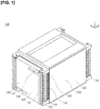
- Figure 1 is a perspective view illustrating the battery pack 100 according to an embodiment.
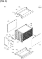
- Figure 2 is a perspective view illustrating a state in which a portion of a bus bar unit 130 (a protective cover 135, an anode-side terminal 133, and a cathode-side terminal 134) as well as a pressurizing unit 120 (an upper pressure plate 121, a lower pressure plate 122, and left and right side plates 123) are removed from the battery pack 100 shown in Figure 1 .
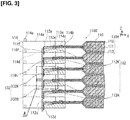
- Figure 3 is a side view illustrating a cross section of a main part of a state in which a bus bar 132 is joined to electrode tabs 112 of stacked unit cells 110.
- Figure 4 is an enlarged view of the location indicated by reference symbol A in Figure 3 .
- Figure 5 is a perspective view illustrating a state in which a bus bar holder 131 and the bus bars 132 are removed from a stacked body 110S illustrated in Figure 2 .
- Figure 6 is a perspective view illustrating a state in which a first cell sub-assembly 110M (three sets of the unit cells 110 connected in parallel) shown in Figure 5 is disassembled for each unit cell 110, and a first spacer 114 and a second spacer 115 are removed from one (the uppermost) unit cell 110 thereof.
- Figure 7 is a perspective view illustrating a state in which the first cell sub-assembly 110M and a second cell sub-assembly 110N shown in Figure 5 are electrically connected by means of the bus bars 132.
- the battery pack 100 generally comprises the unit cells 110, which have a cell body 110H that includes a power-generating element 111 and is formed in a flat shape, and an electrode tab 112 extends out from the cell body 110H, and which are stacked in the thickness direction (Z direction) of the cell body 110H.
- the battery pack 100 comprises a bus bar 132 electrically connected to the electrode tab 112 by laser welding, and a plate portion 112g that forms a stacked structure together with the electrode tab 112 along an irradiation direction (X direction) of the laser L.
- X direction irradiation direction
- a plurality of the battery packs 100 are mounted in a vehicle such as an electric vehicle and used as a power source for driving a vehicle motor.
- the battery pack 100 is configured by electrically connecting, by means of a bus bar unit 130, a stacked body 110S formed by stacking a plurality of the unit cells 110 in a state of being pressurized by a pressurizing unit 120.
- the stacked body 110S is configured by alternately connecting in series the first cell sub-assembly 110M, which comprises three unit cells 110 electrically connected in parallel, and the second cell sub-assembly 110N, which comprises three unit cells 110 electrically connected in parallel, as illustrated in Figure 5 .
- the first cell sub-assembly 110M corresponds to the three unit cells 110 positioned in the first row (lowermost row), the third row, the fifth row, and the seventh row (uppermost row) of the battery pack 100, as illustrated in Figure 5 .
- the second cell sub-assembly 110N corresponds to the three unit cells 110 positioned in the second row, the fourth row, and the sixth row of the battery pack 100, as illustrated in Figure 4 .
- the first cell sub-assembly 110M and the second cell sub-assembly 110N are similarly configured. However, the first cell sub-assembly 110M and the second cell sub-assembly 110N are arranged such that three anode-side electrode tabs 112A and three cathode-side electrode tabs 112K are alternately positioned along the Z direction, by interchanging the tops and bottoms of the three unit cells 110, as illustrated in Figures 5 and 7 .
- each of the distal end portions 112d is bent downward so that the orientations of all of the distal end portions 112d of the electrode tabs 112 of the unit cells 110 are aligned.
- the unit cell 110 corresponds to a lithium ion secondary battery, for example.
- a plurality of the unit cells 110 are connected in series in order to satisfy the drive voltage specification of the vehicle motor.
- a plurality of the unit cells 110 are connected in parallel in order to ensure the battery capacity and extend the travel distance of the vehicle.
- the unit cell 110 comprises the cell body 110H formed in a flat shape and the electrode tab 112 extends out from the cell body 110H, as illustrated in Figure 3 .
- the cell body 110H includes the power-generating element 111 that carries out charging and discharging, and a laminate film 113 for sealing the power-generating element 111.
- the power-generating element 111 is charged by electric power from an outdoor charging station or the like, and supplies driving power to the vehicle motor or the like by discharging the electric power.
- the power-generating element 111 is formed by stacking a plurality of sets of anodes and cathodes separated by separators.
- the electrode tab 112 is for exposing the power-generating element 111 to the outside, as illustrated in Figures 3 to 5 .
- the electrode tab 112 is configured from the anode-side electrode tab 112A and the cathode-side electrode tab 112K.
- the anode-side electrode tab 112A and the cathode-side electrode tab 112K extend out from the cell body 110H toward the same direction, which intersects the thickness direction of the cell body 110H.
- the proximal end side of the anode-side electrode tab 112A is joined to all of the anodes included in one power-generating element 111.
- the anode-side electrode tab 112A is formed in a thin plate shape, and is made of aluminum (Al) in accordance with the characteristics of the anode.
- the anode-side electrode tab 112A is formed in an L shape from a proximal end portion 112c adjacent to the power-generating element 111 to a distal end portion 112d, as illustrated in Figures 3 and 4 .
- the distal end portion 112d of the anode-side electrode tab 112A is bent downward in the Z direction.
- the proximal end side of the cathode-side electrode tab 112K is joined to all of the cathodes included in one power-generating element 111.
- the cathode-side electrode tab 112K is formed in a thin plate shape, and is made of copper in accordance with the characteristics of the cathode.
- the thickness of the cathode-side electrode tab 112K is less than or equal to the thickness of the anode-side electrode tab 112A. In the present embodiment the thickness of the cathode-side electrode tab 112K is half the thickness of the anode-side electrode tab 112A.
- the cathode-side electrode tab 112K is formed in an L shape from a proximal end portion 112e adjacent to the power-generating element 111 to a distal end portion 112f, as illustrated in Figures 3 and 4 .
- the distal end portion 112f of the cathode-side electrode tab 112K is bent downward in the Z direction, and the distal end portion 112f is folded back so as to form the plate portion 112g upward in the Z direction. That is, in the present embodiment the plate portion 112g is integrally formed with the cathode-side electrode tab 112K, and forms a stacked structure together with the cathode-side electrode tab 112K along the irradiation direction of the laser (X direction).
- the plate portion 112g is formed on the side away from a cathode-side bus bar 132K, by folding the distal end portion 112f of the cathode-side electrode tab 112K back onto the side away from the cathode-side bus bar 132K, as illustrated in Figures 3 and 4 .
- the current path can be shortened and the current resistance can be decreased, compared to a configuration in which the plate portion is folded back toward the side closer to the cathode-side bus bar (refer to Figure 8 ).
- the distal end portion 112f of the cathode-side electrode tab 112K is folded back tightly so as not to form a gap.
- the distal end portion 112f of the cathode-side electrode tab 112K may also be folded back so as to form a gap.
- the plate portion 112g As described above it is possible to prevent the laser L from penetrating the cathode-side electrode tab 112K even if the output of the laser L is increased in order to improve the welding quality. Therefore, the cathode-side electrode tab 112K and the cathode-side bus bar 132K can be suitably laser-welded.
- the thickness of the cathode-side electrode tab 112K is half the thickness of the anode-side electrode tab 112A, and the plate portion 112g is provided only on the cathode-side electrode tab 112K. That is, the X direction widths of the distal end portion 112f of the cathode-side electrode tab 112K including the plate portion 112g and of the distal end portion 112d of the anode-side electrode tab 112A become the same, as illustrated in Figure 4 .
- the laminate film 113 is configured in pairs, and is for sealing the power-generating element 111 from above and below along the Z direction, as illustrated in Figure 3 .
- the anode-side electrode tab 112A and the cathode-side electrode tab 112K extend out to the outside from gaps between portions 113a on one end along the Y direction.
- the laminate film 113 comprises a metal foil and a sheet having an insulating property and covering the metal foil from above and below.
- the unit cells 110 are stacked as illustrated in Figures 3 to 5 , in a state of being supported by a pair of spacers (first spacer 114 and second spacer 115), as illustrated in Figure 6 .
- the pair of spacers arrange the unit cells 110 at constant intervals along the Z direction, as illustrated in Figures 2 and 3 .
- the first spacer 114 supports the unit cell 110 on the side provided with the electrode tab 112.
- the second spacer 115 supports the unit cell 110 on the side not provided with the electrode tab 112, so as to oppose the first spacer 114 in the X direction of the unit cell 110.
- the first spacer 114 is formed in an elongated plate shape having recesses and protrusions, as illustrated in Figure 6 , and is made of reinforced plastic having an insulating property.
- the first spacer 114 is provided so as to oppose the one end portion 113a of the pair of laminate films 113.
- the first spacer 114 supports the one end portion 113a of the laminate film 113 by means of a flat supporting surface 114b, as illustrated in Figures 3 and 6 .
- the first spacer 114 has an abutting surface 114h on a wall surface along the Z direction adjacent to the supporting surface 114b.
- the abutting surface 114h positions the distal end portion 112d of the electrode tab 112 along the X direction, as illustrated in Figure 3 .
- the first spacer 114 has a pair of connecting pins 114c protruding upward respectively at both ends of the supporting surface 114b along the Y direction, as illustrated in Figure 6 .
- the pair of connecting pins 114c have a cylindrical shape, and are inserted in connecting holes 113c that open at both ends of the one end portion 113a of the laminate film 113 along the Y direction, thereby positioning the unit cell 110.
- an upper surface 114a of one first spacer 114 and a lower surface 114d of another first spacer 114 are in contact, as illustrated in Figure 3 .
- the plurality of first spacers 114 position each other by the fitting of a cylindrical positioning pin 114e protruding from the upper surface 114a of one first spacer 114 being into a positioning hole 114f opened on the lower surface 114d of another first spacer 114, as illustrated in Figure 3 .
- the first spacer 114 is provided with locating holes 114g at both ends along the Y direction, as illustrated in Figure 6 . Bolts for connecting and positioning a plurality of the battery packs 100 relative to each other along the Z direction are inserted in the locating holes 114g.
- the second spacer 115 is configured by simplifying the first spacer 114, since it is not necessary for the second spacer to support the electrode tab 112.
- the second spacer 115 includes a supporting surface 115b for supporting the other end portion 113b of the laminate film 113, positioning pins 114e for positioning the second spacers relative to each other, connecting pins 115c for positioning the unit cell 110, and locating holes 115g into which bolts for connecting while positioning the plurality of battery packs 100 relative to each other are inserted, as illustrated in Figure 6 .
- the configuration of the pressurizing unit 120 will be described in detail.
- the pressurizing unit 120 includes the upper pressure plate 121 and the lower pressure plate 122, which apply pressure to the power-generating element 111 of each of the unit cells 110 of the stacked body 110S from above and below, and a pair of side plates 123 that fix the upper pressure plate 121 and the lower pressure plate 122 in a state of pressurization of the stacked body 110S.
- the upper pressure plate 121 together with the lower pressure plate 122, hold and sandwich the plurality of the unit cells 110 that constitute the stacked body 110S from above and below, and pressurize the power-generating element 111 of each of the unit cells 110, as illustrated in Figures 1 and 2 .
- the upper pressure plate 121 is formed in a plate shape having recesses and protrusions, and is made of a metal having sufficient rigidity.
- the upper pressure plate 121 is provided on a horizontal plane.
- the upper pressure plate 121 has a pressurizing surface 121a that pressurizes the power-generating element 111 downward, as illustrated in Figure 2 .
- the pressurizing surface 121a is formed flat, protruding downward from a central portion of the upper pressure plate 121.
- the upper pressure plate 121 has locating holes 121b into which bolts for connecting the battery packs 100 to each other are inserted.
- the locating holes 121b are through-holes, and open at the four corners of the upper pressure plate 121.
- the lower pressure plate 122 has the same shape as the upper pressure plate 121, and is provided so that the top and bottom of the upper pressure plate 121 can be inverted, as illustrated in Figure 2 .
- the lower pressure plate 122 includes a pressurizing surface 122a that pressurizes the power-generating element 111 upward, and locating holes 122b into which bolts for connecting and positioning the battery packs 100 relative to each other along the Z direction are inserted.
- the pair of side plates 123 are for fixing the upper pressure plate 121 and the lower pressure plate 122 in a state of pressurization of the stacked body 110S, as illustrated in Figures 1 and 2 . That is, the pair of side plates 123 hold the interval between the upper pressure plate 121 and the lower pressure plate 122 constant. In addition, the pair of side plates 123 cover and protect the side surfaces of the stacked unit cells 110 along the X direction.
- the side plate 123 is formed in a flat plate shape, and is made of metal.
- the pair of side plates 123 stand upright so as to face both side surfaces of the stacked unit cells 110 along the X direction.
- the pair of side plates 123 are welded to the upper pressure plate 121 and the lower pressure plate 122.
- bus bar unit 130 The configuration of the bus bar unit 130 will be described in detail.
- the bus bar unit 130 includes the bus bar holder 131 that integrally holds a plurality of the bus bars 132, the bus bars 132 that electrically interconnect vertically adjacent electrode tabs 112 of the unit cells 110, the anode-side terminal 133 that causes the anode-side terminal ends of the plurality of the electrically connected unit cells 110 to face an external input/output terminal, the cathode-side terminal 134 that causes the cathode-side terminal ends of the plurality of the electrically connected unit cells 110 to oppose an external input/output terminal, and a protective cover 135 for protecting the bus bars 132, and the like.
- the bus bar holder 131 is for integrally holding a plurality of the bus bars 132, as illustrated in Figures 2 and 5 .
- the bus bar holder 131 integrally holds the plurality of the bus bars 132 in a matrix so as to oppose the electrode tab 112 of each of the unit cells 110 of the stacked body 110S.
- the bus bar holder 131 is made of resin having insulating properties, and has the form of a frame.
- the bus bar holder 131 is respectively provided with a pair of columnar support portions 131a that stand upright along the Z direction, so as to be positioned on both sides of the longitudinal direction of the first spacers 114 that support the electrode tabs 112 of the unit cells 110, as illustrated in Figure 5 .
- the pair of columnar support portions 131a are fitted to the side surfaces of the first spacers 114.
- the pair of columnar support portions 131a have the form of an L when viewed along the Z direction, and have the form of a plate extending along the Z direction.
- the bus bar holder 131 is provided with a pair of auxiliary columnar support portions 131b at an interval, erected along the Z direction so as to be positioned in the vicinity of the center of the first spacer 114 in the longitudinal direction.
- the pair of auxiliary columnar support portions 131b have the form of a plate extending along the Z direction.
- the bus bar holder 131 includes insulating portions 131c that respectively protrude between adjacent bus bars 132 along the Z direction, as illustrated in Figure 5 .
- the insulating portions 131c have the shape of a plate extending along the Y direction.
- Each of the insulating portions 131c is provided horizontally between the columnar support portion 131b and the auxiliary columnar support portion 131b.
- the insulating portion 131c prevents discharge by insulating the space between bus bars 132 that are adjacent to each other along the Z direction.
- the bus bar holder 131 may be configured by joining together the columnar support portions 131a, the auxiliary columnar support portions 131b, and the insulating portions 131c, which are independently formed, or may be configured by integrally molding the columnar support portions 131a, the auxiliary columnar support portions 131b, and the insulating portions 131c.
- the bus bars 132 are for electrically interconnecting the vertically adjacent electrode tabs 112 of the unit cells 110, as illustrated in Figures 3 , 5 , and 7 .
- the bus bars 132 electrically connect the anode-side electrode tab 112A of one unit cell 110 and the cathode-side electrode tab 112K of another unit cell 110.
- the bus bars 132 connect three vertically arranged anode-side electrode tabs 112A of the first cell sub-assembly 110M and three vertically arranged cathode-side electrode tabs 112K of the second cell sub-assembly 110N, as illustrated in Figure 7 .
- the bus bars 132 connect the three anode-side electrode tabs 112A of the first cell sub-assembly 110M in parallel and connect the three cathode-side electrode tabs 112K of the second cell sub-assembly 110N in parallel, as illustrated in Figure 7 .
- the bus bars 132 connect the three anode-side electrode tabs 112A of the first cell sub-assembly 110M and the three cathode-side electrode tabs 112K of the second cell sub-assembly 110N in series.
- the bus bars 132 are laser-welded to the anode-side electrode tab 112A of one unit cell 110 and the cathode-side electrode tab 112K of another unit cell 110.
- the bus bar 132 is formed by joining the anode-side bus bar 132A and the cathode-side bus bar 132K, as illustrated in Figures 3 to 5 .
- the anode-side bus bar 132A and the cathode-side bus bar 132K have the same shape, each having in the form of an L.
- the bus bar 132 is integrally formed by a joint portion 132c, which is formed by joining one bent end of the anode-side bus bar 132A, and one bent end of the cathode-side bus bar 132K, as illustrated in Figures 3 to 5 .
- the anode-side bus bar 132A and the cathode-side bus bar 132K, which constitute the bus bar 132, are provided with side portions 132d that are joined to the bus bar holder 131 at both ends along the Y direction, as illustrated in Figure 4 .
- the anode-side bus bar 131A is made of aluminum in the same manner as the anode-side electrode tab 112A of the unit cell 110.
- the cathode-side bus bar 132K is made of copper, in the same manner as the cathode-side electrode tab 112K of the unit cell 110.
- the anode-side bus bar 132A and the cathode-side bus bar 132K, which are made from different metals, are joined to each other by means of ultrasonic bonding, to form the joint portion 132c.
- bus bar 132 positioned on the upper right in the drawing in Figure 5 corresponds to the anode-side terminal ends of 21 unit cells 110 (3 parallel 7 series), and is configured from only the anode-side bus bar 132A.
- This anode-side bus bar 132A is laser-welded to the anode-side electrode tabs 112A of the three uppermost unit cells 110 of the stacked unit cells 110.
- bus bar 132 positioned on the lower left in the drawing in Figure 5 corresponds to the cathode-side terminal ends of 21 unit cells 110 (3 parallel 7 series), and is configured from only the cathode-side bus bar 132K.
- the anode-side terminal 133 causes the anode-side terminal ends of the plurality of the electrically connected unit cells 110 to oppose an external input/output terminal, as illustrated in Figures 1 and 2 .
- the anode-side terminal 133 is joined to the anode-side bus bar 132A positioned on the upper right in the drawing, from among the bus bars 132 arranged in a matrix, as illustrated in Figure 2 .
- the anode-side terminal 133 has the form of a plate, both ends of which are bent, and is made from a conductive metal.
- the cathode-side terminal 134 causes the cathode-side terminal ends of the plurality of the electrically connected unit cells 110 to oppose an external input/output terminal, as illustrated in Figures 1 and 2 .
- the cathode-side terminal 134 is joined to the cathode-side bus bar 132K positioned on the lower left in the drawing, from among the bus bars 132 arranged in a matrix, as illustrated in Figure 2 .
- the cathode-side terminal 134 has a form like that of the anode-side terminal 133 with the top and bottom inverted.
- the protective cover 135 is for protecting the bus bars 132, and the like, as illustrated in Figures 1 and 2 . That is, the protective cover 135 integrally covers the plurality of the bus bars 132 to thereby prevent each of the bus bars 132 from coming into contact with other members, etc., to cause electrical short-circuiting.
- the protective cover 135 is made from a plastic having an insulating property, where one end 135b and the other end 135c of a side surface 135a standing upright along the Z direction are bent claw-like in the X direction, as illustrated in Figure 2 .
- the protective cover 135 covers each of the bus bars 132 with the side surface 135a, while sandwiching and fixing the bus bar holder 131 from above and below with the one end 135b and the other end 135c.
- the protective cover 135 has a first opening 135d, which is a rectangular hole and is for exposing the anode-side terminal 133 to the outside, and a second opening 135e, which is a rectangular hole and is for exposing the cathode-side terminal 134 to the outside, respectively on the side surface 135a.
- bus bar holder 131 that integrally holds each of the bus bars 132 is joined to the side surfaces of the plurality of stacked first spacers 114 by adhesion, or the like.
- the laser L is irradiated toward the cathode-side bus bar 132K and the anode-side bus bar 132A.
- the distal end portion 112f of the cathode-side electrode tab 112K is provided with the plate portion 112g, it is possible to prevent the laser L from penetrating the cathode-side electrode tab 112K even if the output of the laser L is increased in order to improve the welding quality. Therefore, the cathode-side electrode tab 112K and the cathode-side bus bar 132K can be suitably laser-welded.
- the battery pack 100 comprises the unit cells 110, which have the cell body 110H that includes the power-generating element 111 and is formed in a flat shape, and the electrode tab 112 extends out from the cell body 110H, and which are stacked in the thickness direction of the cell body 110H.
- the battery pack 100 comprises the bus bar 132 electrically connected to the electrode tab 112 by laser welding, and the plate portion 112g that forms a stacked structure together with the cathode-side electrode tab 112K along the irradiation direction of the laser L.
- the battery pack 100 configured in this manner, it is possible to prevent the laser L from penetrating the cathode-side electrode tab 112K even if the output of the laser L is increased in order to improve the welding quality. Therefore, the cathode-side electrode tab 112K and the cathode-side bus bar 132K can be suitably laser-welded.
- the distal end portions 112d, 112f of the electrode tabs 112 are formed bent along the stacking direction of the unit cells 110.
- the electrode tabs 112 include the anode-side electrode tab 112A, and the cathode-side electrode tab 112K that has a smaller thickness than the anode-side electrode tab 112A, and the plate portion 112g is provided only on the cathode-side electrode tab 112K. According to this configuration, compared to a configuration in which the plate portion 112g is provided only on the anode-side electrode tab 112A, it is possible to align the positions of the cathode-side bus bar 132K and the anode-side bus bar 132A along the X direction. Therefore, it is possible to more easily laser-weld the electrode tab 112 and the bus bar 132.
- the plate portion 112g is integrally formed with the cathode-side electrode tab 112K by means of the distal end portion 112f of the cathode-side electrode tab 112K being folded back. Therefore, it is not necessary to prepare a separate member as the plate portion, and it is possible to form the plate portion 112g by merely folding back the distal end portion 112f of the cathode-side electrode tab 112K.
- the plate portion 112g is formed on the side away from the cathode-side bus bar 132K, by means of the distal end portion 112f of the cathode-side electrode tab 112K being folded back onto the side away from the cathode-side bus bar 132K. According to this configuration, the current path can be shortened and the current resistance can be decreased, compared to a configuration in which the distal end portion 112f of the cathode-side electrode tab 112K is folded back onto the cathode-side bus bar 132K side.
- Figure 8 is a view of the battery pack 200 according to the first modified example, and corresponds to Figure 4 .
- An electrode tab 212 of the battery pack 200 according to the first modified example includes the anode-side electrode tab 112A and a cathode-side electrode tab 212K, as illustrated in Figure 8 .
- the anode-side electrode tab 112A has the same configuration as the anode-side electrode tab 112A according to the above-described embodiment, so a description thereof will be omitted.
- the cathode-side electrode tab 212K is formed in an L shape from the proximal end portion 112e adjacent to the power-generating element 111 to a distal end portion 212f, as illustrated in Figure 8 .
- the distal end portion 212f of the cathode-side electrode tab 212K is bent downward in the Z direction, and the distal end portion 212f is folded back so as to form a plate portion 212g upward in the Z direction.
- the plate portion 212g according to the first modified example is formed adjacent to the cathode-side bus bar 132K, by folding the distal end portion 212f of the cathode-side electrode tab 212K back onto the side closer to the cathode-side bus bar 132K, as illustrated in Figure 8 .
- the cathode-side electrode tab 212K and the cathode-side bus bar 132K can be suitably laser-welded.
- Figure 9 is a view of the battery pack 300 according to the second modified example, and corresponds to Figure 4 .
- An electrode tab 312 of the battery pack 300 according to the second modified example includes the anode-side electrode tab 112A and a cathode-side electrode tab 312K, as illustrated in Figure 9 .
- the anode-side electrode tab 112A has the same configuration as the anode-side electrode tab 112A according to the above-described embodiment, so a description thereof will be omitted.
- the cathode-side electrode tab 312K is formed in an L shape from the proximal end portion 112e adjacent to the power-generating element 111 to a distal end portion 312f, as illustrated in Figure 9 .
- the distal end portion 312f of the cathode-side electrode tab 312K is bent downward in the Z direction.
- the cathode-side electrode tab 312K according to the second modified example is not configured such that the plate portion is formed upward in the Z direction by folding back the distal end portion 312f. Instead, in the second modified example a plate portion 301 is disposed as a separate body from the cathode-side electrode tab 312K.
- the plate portion 301 is positioned on the side of the cathode-side electrode tab 312K opposite the side on which the cathode-side bus bar 132K is provided.
- the plate portion 301 is fixed to the cathode-side electrode tab 312K or the abutting surface 114h of the first spacer 114 in advance.
- the material constituting the plate portion 301 is not particularly limited, but preferably is a metal material, from the perspective of more suitably preventing penetration by the laser L.
- the cathode-side electrode tab 312K and the cathode-side bus bar 132K can be suitably laser-welded.
- Figure 10 is a view of the battery pack 400 according to the third modified example, and corresponds to Figure 4 .
- An electrode tab 412 of the battery pack 400 according to the third modified example includes the anode-side electrode tab 112A and a cathode-side electrode tab 412K, as illustrated in Figure 10 .
- the anode-side electrode tab 112A has the same configuration as the anode-side electrode tab 112A according to the above-described embodiment, so a description thereof will be omitted.
- the cathode-side electrode tab 412K is formed in an L shape from the proximal end portion 112e adjacent to the power-generating element 111 to a distal end portion 412f, as illustrated in Figure 10 .
- the distal end portion 412f of the cathode-side electrode tab 412K is bent downward in the Z direction.
- the cathode-side electrode tab 412K according to the third modified example is not configured such that the plate portion is formed upward in the Z direction by folding back the distal end portion 412f. Instead, in the third modified example a plate portion 401 is disposed as a separate body from the cathode-side electrode tab 412K.
- the plate portion 401 is positioned between the cathode-side bus bar 132K and the cathode-side electrode tab 412K.
- the plate portion 401 is fixed to the cathode-side electrode tab 412K or the cathode-side bus bar 132K in advance.
- the material constituting the plate portion 401 is not particularly limited as long as the material has conductivity.
- the cathode-side electrode tab 412K and the cathode-side bus bar 132K can be suitably laser-welded.
- the distal end portions 112d, 112f of the electrode tab 112 are bent along the stacking direction of the unit cells 110, but the distal end portions may be configured so as not to be bent.
- the plate portion 112g is provided only on the cathode-side electrode tab 112K.
- the plate portion may be provided on the cathode-side electrode tab 112K and the anode-side electrode tab 112A.
- the plate portion may be provided only on the anode-side electrode tab 112A.
Landscapes
- Chemical & Material Sciences (AREA)
- Chemical Kinetics & Catalysis (AREA)
- Electrochemistry (AREA)
- General Chemical & Material Sciences (AREA)
- Engineering & Computer Science (AREA)
- Physics & Mathematics (AREA)
- Optics & Photonics (AREA)
- Plasma & Fusion (AREA)
- Mechanical Engineering (AREA)
- Manufacturing & Machinery (AREA)
- Connection Of Batteries Or Terminals (AREA)
- Battery Mounting, Suspending (AREA)
Abstract
Description
- The present invention relates to a battery pack.
- A battery pack is, for example, mounted on a vehicle such as an electric vehicle and used as a power source for driving a vehicle motor. A battery pack is configured by stacking a plurality of unit cells. In the stacked unit cells, electrode tabs (battery terminals) that are extend out from each unit cell are electrically connected to each other by means of bus bars (bus bar/jumper) (refer to Patent Document 1). In addition, the connection between the electrode tabs and the bus bars is carried out by laser welding.
- Patent Document 1: Japanese Laid Open Patent Application No.
2012-515418 - In the configuration of
Patent Document 1, when connecting the electrode tabs and the bus bars by laser irradiation, if the laser output is increased in order to improve the welding quality there is a possibility that the laser will penetrate the electrode tabs and that suitable welding cannot be achieved. - An object of the present invention is to provide a battery pack in which electrode tabs and bus bars can be suitably laser-welded by preventing the laser from penetrating the electrode tabs, even if the laser output is increased in order to improve the welding quality.
- In order to achieve the object described above, a battery pack according to the present invention comprises unit cells that each includes a cell body having a power-generating element and being formed in a flat shape and in which an electrode tab extends out from the cell body, and which are stacked in a thickness direction of the cell bodies. In addition, the battery pack comprises a bus bar electrically connected to the electrode tab by laser welding, and a plate portion that forms a stacked structure together with the electrode tab along an irradiation direction of the laser.
- By means of the battery pack of the present invention having the configuration described above, electrode tabs and bus bars can be suitably laser-welded by preventing the laser from penetrating the electrode tabs even if the laser output is increased in order to improve the welding quality.
-
- [
Figure 1 ] is a perspective view illustrating a battery pack according to an embodiment. - [
Figure 2 ] is a perspective view illustrating a state in which a portion of a bus bar unit (a protective cover, an anode-side terminal, and a cathode-side terminal) as well as a pressurizing unit (an upper pressure plate, a lower pressure plate, and left and right side plates) are removed from the battery pack shown inFigure 1 . - [
Figure 3 ] is a side view illustrating a cross section of a main part of a state in which a bus bar is joined to electrode tabs of stacked unit cells. - [
Figure 4 ] is an enlarged view of the location indicated by reference symbol A inFigure 3 . - [
Figure 5 ] is a perspective view illustrating a state in which a bus bar holder and the bus bars are removed from the stacked body illustrated inFigure 2 . - [
Figure 6 ] is a perspective view illustrating a state in which a first cell sub-assembly (three sets of unit cells connected in parallel) shown inFigure 5 is disassembled for each unit cell, and a first spacer and a second spacer are removed from one (the uppermost) unit cell thereof. - [
Figure 7 ] is a perspective view illustrating a state in which the first cell sub-assembly and a second cell sub-assembly shown inFigure 5 are electrically connected by means of bus bars. The perspective view shows a state in which the bus bar holder and the bus bars are removed. - [
Figure 8 ] is a view of a battery pack according to a first modified example, and corresponds toFigure 4 . - [
Figure 9 ] is a view of a battery pack according to a second modified example, and corresponds toFigure 4 . - [
Figure 10 ] is a view of a battery pack according to a third modified example, and corresponds toFigure 4 . - An embodiment of the present invention will be explained below with reference to the appended drawings. In the drawings, the same members have been assigned the same reference symbols, and redundant explanations have been omitted. In the drawings, the sizes and ratios of the members have been exaggerated to facilitate understanding the embodiment, and may be different from the actual sizes and ratios.
- In each drawing the orientation of a
battery pack 100 is shown using arrows indicated by X, Y, and Z. The direction of the arrow indicated by X is the longitudinal direction of thebattery pack 100. The direction of the arrow indicated by Y is the transverse direction of thebattery pack 100. The direction of the arrow indicated by Z is the stacking direction of thebattery pack 100. -
Figure 1 is a perspective view illustrating thebattery pack 100 according to an embodiment.Figure 2 is a perspective view illustrating a state in which a portion of a bus bar unit 130 (aprotective cover 135, an anode-side terminal 133, and a cathode-side terminal 134) as well as a pressurizing unit 120 (anupper pressure plate 121, alower pressure plate 122, and left and right side plates 123) are removed from thebattery pack 100 shown inFigure 1 .Figure 3 is a side view illustrating a cross section of a main part of a state in which abus bar 132 is joined toelectrode tabs 112 of stackedunit cells 110.Figure 4 is an enlarged view of the location indicated by reference symbol A inFigure 3 .Figure 5 is a perspective view illustrating a state in which abus bar holder 131 and thebus bars 132 are removed from a stackedbody 110S illustrated inFigure 2 .Figure 6 is a perspective view illustrating a state in which afirst cell sub-assembly 110M (three sets of theunit cells 110 connected in parallel) shown inFigure 5 is disassembled for eachunit cell 110, and afirst spacer 114 and asecond spacer 115 are removed from one (the uppermost)unit cell 110 thereof.Figure 7 is a perspective view illustrating a state in which thefirst cell sub-assembly 110M and asecond cell sub-assembly 110N shown inFigure 5 are electrically connected by means of thebus bars 132. - As illustrated in
Figure 3 , thebattery pack 100 according to the present embodiment generally comprises theunit cells 110, which have acell body 110H that includes a power-generatingelement 111 and is formed in a flat shape, and anelectrode tab 112 extends out from thecell body 110H, and which are stacked in the thickness direction (Z direction) of thecell body 110H. In addition, thebattery pack 100 comprises abus bar 132 electrically connected to theelectrode tab 112 by laser welding, and aplate portion 112g that forms a stacked structure together with theelectrode tab 112 along an irradiation direction (X direction) of the laser L. Each configuration of thebattery pack 100 will be described below. - A plurality of the
battery packs 100 are mounted in a vehicle such as an electric vehicle and used as a power source for driving a vehicle motor. Thebattery pack 100 is configured by electrically connecting, by means of abus bar unit 130, a stackedbody 110S formed by stacking a plurality of theunit cells 110 in a state of being pressurized by a pressurizingunit 120. - The configuration of the stacked
body 110S will be described in detail. - The stacked
body 110S is configured by alternately connecting in series thefirst cell sub-assembly 110M, which comprises threeunit cells 110 electrically connected in parallel, and thesecond cell sub-assembly 110N, which comprises threeunit cells 110 electrically connected in parallel, as illustrated inFigure 5 . - The
first cell sub-assembly 110M corresponds to the threeunit cells 110 positioned in the first row (lowermost row), the third row, the fifth row, and the seventh row (uppermost row) of thebattery pack 100, as illustrated inFigure 5 . Thesecond cell sub-assembly 110N corresponds to the threeunit cells 110 positioned in the second row, the fourth row, and the sixth row of thebattery pack 100, as illustrated inFigure 4 . - The
first cell sub-assembly 110M and thesecond cell sub-assembly 110N are similarly configured. However, thefirst cell sub-assembly 110M and thesecond cell sub-assembly 110N are arranged such that three anode-side electrode tabs 112A and three cathode-side electrode tabs 112K are alternately positioned along the Z direction, by interchanging the tops and bottoms of the threeunit cells 110, as illustrated inFigures 5 and7 . - In the
first cell sub-assembly 110M all of the anode-side electrode tabs 112A are positioned on the right side in the drawing, and all of the cathode-side electrode tabs 112K are positioned on the left side in the drawing, as illustrated inFigures 5 to 7 . - In the
second cell sub-assembly 110N all of the anode-side electrode tabs 112A are positioned on the left side in the drawing, and all of the cathode-side electrode tabs 112K are positioned on the right side in the drawing, as illustrated inFigures 5 to 7 . If the tops and bottoms are simply interchanged every three of theunit cells 110, the orientations of thedistal end portions 112d of theelectrode tabs 112 will vary vertically in the Z direction. Therefore, each of thedistal end portions 112d is bent downward so that the orientations of all of thedistal end portions 112d of theelectrode tabs 112 of theunit cells 110 are aligned. - The
unit cell 110 corresponds to a lithium ion secondary battery, for example. A plurality of theunit cells 110 are connected in series in order to satisfy the drive voltage specification of the vehicle motor. A plurality of theunit cells 110 are connected in parallel in order to ensure the battery capacity and extend the travel distance of the vehicle. - The
unit cell 110 comprises thecell body 110H formed in a flat shape and theelectrode tab 112 extends out from thecell body 110H, as illustrated inFigure 3 . Thecell body 110H includes the power-generatingelement 111 that carries out charging and discharging, and alaminate film 113 for sealing the power-generatingelement 111. - The power-generating
element 111 is charged by electric power from an outdoor charging station or the like, and supplies driving power to the vehicle motor or the like by discharging the electric power. The power-generatingelement 111 is formed by stacking a plurality of sets of anodes and cathodes separated by separators. - The
electrode tab 112 is for exposing the power-generatingelement 111 to the outside, as illustrated inFigures 3 to 5 . Theelectrode tab 112 is configured from the anode-side electrode tab 112A and the cathode-side electrode tab 112K. The anode-side electrode tab 112A and the cathode-side electrode tab 112K extend out from thecell body 110H toward the same direction, which intersects the thickness direction of thecell body 110H. - The proximal end side of the anode-
side electrode tab 112A is joined to all of the anodes included in one power-generatingelement 111. The anode-side electrode tab 112A is formed in a thin plate shape, and is made of aluminum (Al) in accordance with the characteristics of the anode. - The anode-
side electrode tab 112A is formed in an L shape from aproximal end portion 112c adjacent to the power-generatingelement 111 to adistal end portion 112d, as illustrated inFigures 3 and4 . Thedistal end portion 112d of the anode-side electrode tab 112A is bent downward in the Z direction. - The proximal end side of the cathode-
side electrode tab 112K is joined to all of the cathodes included in one power-generatingelement 111. The cathode-side electrode tab 112K is formed in a thin plate shape, and is made of copper in accordance with the characteristics of the cathode. - The thickness of the cathode-
side electrode tab 112K is less than or equal to the thickness of the anode-side electrode tab 112A. In the present embodiment the thickness of the cathode-side electrode tab 112K is half the thickness of the anode-side electrode tab 112A. - The cathode-
side electrode tab 112K is formed in an L shape from aproximal end portion 112e adjacent to the power-generatingelement 111 to adistal end portion 112f, as illustrated inFigures 3 and4 . Thedistal end portion 112f of the cathode-side electrode tab 112K is bent downward in the Z direction, and thedistal end portion 112f is folded back so as to form theplate portion 112g upward in the Z direction. That is, in the present embodiment theplate portion 112g is integrally formed with the cathode-side electrode tab 112K, and forms a stacked structure together with the cathode-side electrode tab 112K along the irradiation direction of the laser (X direction). - The
plate portion 112g is formed on the side away from a cathode-side bus bar 132K, by folding thedistal end portion 112f of the cathode-side electrode tab 112K back onto the side away from the cathode-side bus bar 132K, as illustrated inFigures 3 and4 . By folding the plate portion back onto the side away from the cathode-side bus bar 132K in this manner the current path can be shortened and the current resistance can be decreased, compared to a configuration in which the plate portion is folded back toward the side closer to the cathode-side bus bar (refer toFigure 8 ). - In the present embodiment the
distal end portion 112f of the cathode-side electrode tab 112K is folded back tightly so as not to form a gap. Thedistal end portion 112f of the cathode-side electrode tab 112K may also be folded back so as to form a gap. By forming a gap in this manner, it is possible to attenuate the output of the laser L at the gap; therefore, it is possible to more suitably prevent the laser L from penetrating the cathode-side electrode tab 112K even if the output of the laser L is increased in order to improve the welding quality. - By forming the
plate portion 112g as described above it is possible to prevent the laser L from penetrating the cathode-side electrode tab 112K even if the output of the laser L is increased in order to improve the welding quality. Therefore, the cathode-side electrode tab 112K and the cathode-side bus bar 132K can be suitably laser-welded. - In addition, the following effects can be obtained when the thickness of the cathode-
side electrode tab 112K is half the thickness of the anode-side electrode tab 112A, and theplate portion 112g is provided only on the cathode-side electrode tab 112K. That is, the X direction widths of thedistal end portion 112f of the cathode-side electrode tab 112K including theplate portion 112g and of thedistal end portion 112d of the anode-side electrode tab 112A become the same, as illustrated inFigure 4 . Therefore, since the X direction positions of the cathode-side bus bar 132K and an anode-side bus bar 132A are aligned, it is not necessary to move the focal position of the laser L in the X direction, and theelectrode tab 112 and thebus bar 132 can be more easily laser-welded. - The
laminate film 113 is configured in pairs, and is for sealing the power-generatingelement 111 from above and below along the Z direction, as illustrated inFigure 3 . In the pair oflaminate films 113, the anode-side electrode tab 112A and the cathode-side electrode tab 112K extend out to the outside from gaps betweenportions 113a on one end along the Y direction. Thelaminate film 113 comprises a metal foil and a sheet having an insulating property and covering the metal foil from above and below. - The
unit cells 110 are stacked as illustrated inFigures 3 to 5 , in a state of being supported by a pair of spacers (first spacer 114 and second spacer 115), as illustrated inFigure 6 . - The pair of spacers (
first spacer 114 and second spacer 115) arrange theunit cells 110 at constant intervals along the Z direction, as illustrated inFigures 2 and3 . Thefirst spacer 114 supports theunit cell 110 on the side provided with theelectrode tab 112. Thesecond spacer 115 supports theunit cell 110 on the side not provided with theelectrode tab 112, so as to oppose thefirst spacer 114 in the X direction of theunit cell 110. - The
first spacer 114 is formed in an elongated plate shape having recesses and protrusions, as illustrated inFigure 6 , and is made of reinforced plastic having an insulating property. Thefirst spacer 114 is provided so as to oppose the oneend portion 113a of the pair oflaminate films 113. Thefirst spacer 114 supports the oneend portion 113a of thelaminate film 113 by means of a flat supportingsurface 114b, as illustrated inFigures 3 and6 . Thefirst spacer 114 has anabutting surface 114h on a wall surface along the Z direction adjacent to the supportingsurface 114b. The abuttingsurface 114h positions thedistal end portion 112d of theelectrode tab 112 along the X direction, as illustrated inFigure 3 . Thefirst spacer 114 has a pair of connectingpins 114c protruding upward respectively at both ends of the supportingsurface 114b along the Y direction, as illustrated inFigure 6 . The pair of connectingpins 114c have a cylindrical shape, and are inserted in connectingholes 113c that open at both ends of the oneend portion 113a of thelaminate film 113 along the Y direction, thereby positioning theunit cell 110. - In the plurality of
first spacers 114, anupper surface 114a of onefirst spacer 114 and alower surface 114d of anotherfirst spacer 114 are in contact, as illustrated inFigure 3 . The plurality offirst spacers 114 position each other by the fitting of acylindrical positioning pin 114e protruding from theupper surface 114a of onefirst spacer 114 being into apositioning hole 114f opened on thelower surface 114d of anotherfirst spacer 114, as illustrated inFigure 3 . Thefirst spacer 114 is provided with locatingholes 114g at both ends along the Y direction, as illustrated inFigure 6 . Bolts for connecting and positioning a plurality of the battery packs 100 relative to each other along the Z direction are inserted in the locatingholes 114g. - The
second spacer 115 is configured by simplifying thefirst spacer 114, since it is not necessary for the second spacer to support theelectrode tab 112. Thesecond spacer 115 includes a supportingsurface 115b for supporting theother end portion 113b of thelaminate film 113,positioning pins 114e for positioning the second spacers relative to each other, connectingpins 115c for positioning theunit cell 110, and locatingholes 115g into which bolts for connecting while positioning the plurality of battery packs 100 relative to each other are inserted, as illustrated inFigure 6 . - The configuration of the pressurizing
unit 120 will be described in detail. - The pressurizing
unit 120 includes theupper pressure plate 121 and thelower pressure plate 122, which apply pressure to the power-generatingelement 111 of each of theunit cells 110 of thestacked body 110S from above and below, and a pair ofside plates 123 that fix theupper pressure plate 121 and thelower pressure plate 122 in a state of pressurization of thestacked body 110S. - The
upper pressure plate 121, together with thelower pressure plate 122, hold and sandwich the plurality of theunit cells 110 that constitute thestacked body 110S from above and below, and pressurize the power-generatingelement 111 of each of theunit cells 110, as illustrated inFigures 1 and2 . Theupper pressure plate 121 is formed in a plate shape having recesses and protrusions, and is made of a metal having sufficient rigidity. Theupper pressure plate 121 is provided on a horizontal plane. Theupper pressure plate 121 has a pressurizingsurface 121a that pressurizes the power-generatingelement 111 downward, as illustrated inFigure 2 . The pressurizingsurface 121a is formed flat, protruding downward from a central portion of theupper pressure plate 121. Theupper pressure plate 121 has locatingholes 121b into which bolts for connecting the battery packs 100 to each other are inserted. The locatingholes 121b are through-holes, and open at the four corners of theupper pressure plate 121. - The
lower pressure plate 122 has the same shape as theupper pressure plate 121, and is provided so that the top and bottom of theupper pressure plate 121 can be inverted, as illustrated inFigure 2 . Like theupper pressure plate 121, thelower pressure plate 122 includes a pressurizingsurface 122a that pressurizes the power-generatingelement 111 upward, and locatingholes 122b into which bolts for connecting and positioning the battery packs 100 relative to each other along the Z direction are inserted. - The pair of
side plates 123 are for fixing theupper pressure plate 121 and thelower pressure plate 122 in a state of pressurization of thestacked body 110S, as illustrated inFigures 1 and2 . That is, the pair ofside plates 123 hold the interval between theupper pressure plate 121 and thelower pressure plate 122 constant. In addition, the pair ofside plates 123 cover and protect the side surfaces of the stackedunit cells 110 along the X direction. Theside plate 123 is formed in a flat plate shape, and is made of metal. The pair ofside plates 123 stand upright so as to face both side surfaces of the stackedunit cells 110 along the X direction. The pair ofside plates 123 are welded to theupper pressure plate 121 and thelower pressure plate 122. - The configuration of the
bus bar unit 130 will be described in detail. - The
bus bar unit 130 includes thebus bar holder 131 that integrally holds a plurality of the bus bars 132, the bus bars 132 that electrically interconnect verticallyadjacent electrode tabs 112 of theunit cells 110, the anode-side terminal 133 that causes the anode-side terminal ends of the plurality of the electrically connectedunit cells 110 to face an external input/output terminal, the cathode-side terminal 134 that causes the cathode-side terminal ends of the plurality of the electrically connectedunit cells 110 to oppose an external input/output terminal, and aprotective cover 135 for protecting the bus bars 132, and the like. - The
bus bar holder 131 is for integrally holding a plurality of the bus bars 132, as illustrated inFigures 2 and5 . Thebus bar holder 131 integrally holds the plurality of the bus bars 132 in a matrix so as to oppose theelectrode tab 112 of each of theunit cells 110 of thestacked body 110S. Thebus bar holder 131 is made of resin having insulating properties, and has the form of a frame. - The
bus bar holder 131 is respectively provided with a pair ofcolumnar support portions 131a that stand upright along the Z direction, so as to be positioned on both sides of the longitudinal direction of thefirst spacers 114 that support theelectrode tabs 112 of theunit cells 110, as illustrated inFigure 5 . The pair ofcolumnar support portions 131a are fitted to the side surfaces of thefirst spacers 114. The pair ofcolumnar support portions 131a have the form of an L when viewed along the Z direction, and have the form of a plate extending along the Z direction. Thebus bar holder 131 is provided with a pair of auxiliarycolumnar support portions 131b at an interval, erected along the Z direction so as to be positioned in the vicinity of the center of thefirst spacer 114 in the longitudinal direction. The pair of auxiliarycolumnar support portions 131b have the form of a plate extending along the Z direction. - The
bus bar holder 131 includes insulating portions 131c that respectively protrude betweenadjacent bus bars 132 along the Z direction, as illustrated inFigure 5 . The insulating portions 131c have the shape of a plate extending along the Y direction. Each of the insulating portions 131c is provided horizontally between thecolumnar support portion 131b and the auxiliarycolumnar support portion 131b. The insulating portion 131c prevents discharge by insulating the space betweenbus bars 132 that are adjacent to each other along the Z direction. - The
bus bar holder 131 may be configured by joining together thecolumnar support portions 131a, the auxiliarycolumnar support portions 131b, and the insulating portions 131c, which are independently formed, or may be configured by integrally molding thecolumnar support portions 131a, the auxiliarycolumnar support portions 131b, and the insulating portions 131c. - The bus bars 132 are for electrically interconnecting the vertically
adjacent electrode tabs 112 of theunit cells 110, as illustrated inFigures 3 ,5 , and7 . The bus bars 132 electrically connect the anode-side electrode tab 112A of oneunit cell 110 and the cathode-side electrode tab 112K of anotherunit cell 110. For example, the bus bars 132 connect three vertically arranged anode-side electrode tabs 112A of thefirst cell sub-assembly 110M and three vertically arranged cathode-side electrode tabs 112K of thesecond cell sub-assembly 110N, as illustrated inFigure 7 . - That is, for example, the bus bars 132 connect the three anode-
side electrode tabs 112A of thefirst cell sub-assembly 110M in parallel and connect the three cathode-side electrode tabs 112K of thesecond cell sub-assembly 110N in parallel, as illustrated inFigure 7 . Moreover, the bus bars 132 connect the three anode-side electrode tabs 112A of thefirst cell sub-assembly 110M and the three cathode-side electrode tabs 112K of thesecond cell sub-assembly 110N in series. The bus bars 132 are laser-welded to the anode-side electrode tab 112A of oneunit cell 110 and the cathode-side electrode tab 112K of anotherunit cell 110. - The
bus bar 132 is formed by joining the anode-side bus bar 132A and the cathode-side bus bar 132K, as illustrated inFigures 3 to 5 . The anode-side bus bar 132A and the cathode-side bus bar 132K have the same shape, each having in the form of an L.The bus bar 132 is integrally formed by ajoint portion 132c, which is formed by joining one bent end of the anode-side bus bar 132A, and one bent end of the cathode-side bus bar 132K, as illustrated inFigures 3 to 5 . The anode-side bus bar 132A and the cathode-side bus bar 132K, which constitute thebus bar 132, are provided withside portions 132d that are joined to thebus bar holder 131 at both ends along the Y direction, as illustrated inFigure 4 . - The anode-side bus bar 131A is made of aluminum in the same manner as the anode-
side electrode tab 112A of theunit cell 110. The cathode-side bus bar 132K is made of copper, in the same manner as the cathode-side electrode tab 112K of theunit cell 110. The anode-side bus bar 132A and the cathode-side bus bar 132K, which are made from different metals, are joined to each other by means of ultrasonic bonding, to form thejoint portion 132c. - Of the bus bars 132 arranged in the form of a matrix, the
bus bar 132 positioned on the upper right in the drawing inFigure 5 corresponds to the anode-side terminal ends of 21 unit cells 110 (3 parallel 7 series), and is configured from only the anode-side bus bar 132A. This anode-side bus bar 132A is laser-welded to the anode-side electrode tabs 112A of the threeuppermost unit cells 110 of the stackedunit cells 110. - Of the bus bars 132 arranged in the form of a matrix, the
bus bar 132 positioned on the lower left in the drawing inFigure 5 corresponds to the cathode-side terminal ends of 21 unit cells 110 (3 parallel 7 series), and is configured from only the cathode-side bus bar 132K. - The anode-
side terminal 133 causes the anode-side terminal ends of the plurality of the electrically connectedunit cells 110 to oppose an external input/output terminal, as illustrated inFigures 1 and2 . The anode-side terminal 133 is joined to the anode-side bus bar 132A positioned on the upper right in the drawing, from among the bus bars 132 arranged in a matrix, as illustrated inFigure 2 . The anode-side terminal 133 has the form of a plate, both ends of which are bent, and is made from a conductive metal. - The cathode-
side terminal 134 causes the cathode-side terminal ends of the plurality of the electrically connectedunit cells 110 to oppose an external input/output terminal, as illustrated inFigures 1 and2 . The cathode-side terminal 134 is joined to the cathode-side bus bar 132K positioned on the lower left in the drawing, from among the bus bars 132 arranged in a matrix, as illustrated inFigure 2 . The cathode-side terminal 134 has a form like that of the anode-side terminal 133 with the top and bottom inverted. - The
protective cover 135 is for protecting the bus bars 132, and the like, as illustrated inFigures 1 and2 . That is, theprotective cover 135 integrally covers the plurality of the bus bars 132 to thereby prevent each of the bus bars 132 from coming into contact with other members, etc., to cause electrical short-circuiting. Theprotective cover 135 is made from a plastic having an insulating property, where oneend 135b and theother end 135c of aside surface 135a standing upright along the Z direction are bent claw-like in the X direction, as illustrated inFigure 2 . - The
protective cover 135 covers each of the bus bars 132 with theside surface 135a, while sandwiching and fixing thebus bar holder 131 from above and below with the oneend 135b and theother end 135c. Theprotective cover 135 has afirst opening 135d, which is a rectangular hole and is for exposing the anode-side terminal 133 to the outside, and a second opening 135e, which is a rectangular hole and is for exposing the cathode-side terminal 134 to the outside, respectively on theside surface 135a. - Next, a method for welding the bus bars 132 to the
electrode tabs 112 in thebattery pack 100 according to the present embodiment will be described with reference toFigure 4 . - First, the
bus bar holder 131 that integrally holds each of the bus bars 132 is joined to the side surfaces of the plurality of stackedfirst spacers 114 by adhesion, or the like. - At this time since the
plate portion 112g is provided only on the cathode-side electrode tab 112K, the positions of the cathode-side bus bar 132K and the anode-side bus bar 132A along the X direction are aligned, as illustrated inFigure 4 . - In this state, the laser L is irradiated toward the cathode-
side bus bar 132K and the anode-side bus bar 132A. At this time, because thedistal end portion 112f of the cathode-side electrode tab 112K is provided with theplate portion 112g, it is possible to prevent the laser L from penetrating the cathode-side electrode tab 112K even if the output of the laser L is increased in order to improve the welding quality. Therefore, the cathode-side electrode tab 112K and the cathode-side bus bar 132K can be suitably laser-welded. - As described above, the
battery pack 100 according to the present embodiment comprises theunit cells 110, which have thecell body 110H that includes the power-generatingelement 111 and is formed in a flat shape, and theelectrode tab 112 extends out from thecell body 110H, and which are stacked in the thickness direction of thecell body 110H. In addition, thebattery pack 100 comprises thebus bar 132 electrically connected to theelectrode tab 112 by laser welding, and theplate portion 112g that forms a stacked structure together with the cathode-side electrode tab 112K along the irradiation direction of the laser L. By means of thebattery pack 100 configured in this manner, it is possible to prevent the laser L from penetrating the cathode-side electrode tab 112K even if the output of the laser L is increased in order to improve the welding quality. Therefore, the cathode-side electrode tab 112K and the cathode-side bus bar 132K can be suitably laser-welded. - Additionally, the
distal end portions electrode tabs 112 are formed bent along the stacking direction of theunit cells 110. Moreover, theelectrode tabs 112 include the anode-side electrode tab 112A, and the cathode-side electrode tab 112K that has a smaller thickness than the anode-side electrode tab 112A, and theplate portion 112g is provided only on the cathode-side electrode tab 112K. According to this configuration, compared to a configuration in which theplate portion 112g is provided only on the anode-side electrode tab 112A, it is possible to align the positions of the cathode-side bus bar 132K and the anode-side bus bar 132A along the X direction. Therefore, it is possible to more easily laser-weld theelectrode tab 112 and thebus bar 132. - In addition, the
plate portion 112g is integrally formed with the cathode-side electrode tab 112K by means of thedistal end portion 112f of the cathode-side electrode tab 112K being folded back. Therefore, it is not necessary to prepare a separate member as the plate portion, and it is possible to form theplate portion 112g by merely folding back thedistal end portion 112f of the cathode-side electrode tab 112K. - Additionally, the
plate portion 112g is formed on the side away from the cathode-side bus bar 132K, by means of thedistal end portion 112f of the cathode-side electrode tab 112K being folded back onto the side away from the cathode-side bus bar 132K. According to this configuration, the current path can be shortened and the current resistance can be decreased, compared to a configuration in which thedistal end portion 112f of the cathode-side electrode tab 112K is folded back onto the cathode-side bus bar 132K side. - Next, the configuration of a
battery pack 200 according to a first modified example will be described with reference toFigure 8. Figure 8 is a view of thebattery pack 200 according to the first modified example, and corresponds toFigure 4 . - An
electrode tab 212 of thebattery pack 200 according to the first modified example includes the anode-side electrode tab 112A and a cathode-side electrode tab 212K, as illustrated inFigure 8 . The anode-side electrode tab 112A has the same configuration as the anode-side electrode tab 112A according to the above-described embodiment, so a description thereof will be omitted. - The cathode-
side electrode tab 212K is formed in an L shape from theproximal end portion 112e adjacent to the power-generatingelement 111 to adistal end portion 212f, as illustrated inFigure 8 . Thedistal end portion 212f of the cathode-side electrode tab 212K is bent downward in the Z direction, and thedistal end portion 212f is folded back so as to form aplate portion 212g upward in the Z direction. - The
plate portion 212g according to the first modified example is formed adjacent to the cathode-side bus bar 132K, by folding thedistal end portion 212f of the cathode-side electrode tab 212K back onto the side closer to the cathode-side bus bar 132K, as illustrated inFigure 8 . - As described above, by means of the
battery pack 200 of the first modified example it is possible to prevent the laser L from penetrating the cathode-side electrode tab 212K even if the output of the laser L is increased in order to improve the welding quality. Therefore, the cathode-side electrode tab 212K and the cathode-side bus bar 132K can be suitably laser-welded. - Next, the configuration of a
battery pack 300 according to a second modified example will be described with reference toFigure 9. Figure 9 is a view of thebattery pack 300 according to the second modified example, and corresponds toFigure 4 . - An
electrode tab 312 of thebattery pack 300 according to the second modified example includes the anode-side electrode tab 112A and a cathode-side electrode tab 312K, as illustrated inFigure 9 . The anode-side electrode tab 112A has the same configuration as the anode-side electrode tab 112A according to the above-described embodiment, so a description thereof will be omitted. - The cathode-
side electrode tab 312K is formed in an L shape from theproximal end portion 112e adjacent to the power-generatingelement 111 to adistal end portion 312f, as illustrated inFigure 9 . Thedistal end portion 312f of the cathode-side electrode tab 312K is bent downward in the Z direction. In addition, unlike the cathode-side electrode tab 112K according to the embodiment, the cathode-side electrode tab 312K according to the second modified example is not configured such that the plate portion is formed upward in the Z direction by folding back thedistal end portion 312f. Instead, in the second modified example aplate portion 301 is disposed as a separate body from the cathode-side electrode tab 312K. - The
plate portion 301 is positioned on the side of the cathode-side electrode tab 312K opposite the side on which the cathode-side bus bar 132K is provided. Theplate portion 301 is fixed to the cathode-side electrode tab 312K or theabutting surface 114h of thefirst spacer 114 in advance. - The material constituting the
plate portion 301 is not particularly limited, but preferably is a metal material, from the perspective of more suitably preventing penetration by the laser L. - As described above, by means of the
battery pack 300 of the second modified example it is possible to prevent the laser L from penetrating the cathode-side electrode tab 312K even if the output of the laser L is increased in order to improve the welding quality. Therefore, the cathode-side electrode tab 312K and the cathode-side bus bar 132K can be suitably laser-welded. - Next, the configuration of a
battery pack 400 according to a third modified example will be described with reference toFigure 10. Figure 10 is a view of thebattery pack 400 according to the third modified example, and corresponds toFigure 4 . - An
electrode tab 412 of thebattery pack 400 according to the third modified example includes the anode-side electrode tab 112A and a cathode-side electrode tab 412K, as illustrated inFigure 10 . The anode-side electrode tab 112A has the same configuration as the anode-side electrode tab 112A according to the above-described embodiment, so a description thereof will be omitted. - The cathode-
side electrode tab 412K is formed in an L shape from theproximal end portion 112e adjacent to the power-generatingelement 111 to a distal end portion 412f, as illustrated inFigure 10 . The distal end portion 412f of the cathode-side electrode tab 412K is bent downward in the Z direction. In addition, unlike the cathode-side electrode tab 112K according to the embodiment, the cathode-side electrode tab 412K according to the third modified example is not configured such that the plate portion is formed upward in the Z direction by folding back the distal end portion 412f. Instead, in the third modified example aplate portion 401 is disposed as a separate body from the cathode-side electrode tab 412K. - The
plate portion 401 is positioned between the cathode-side bus bar 132K and the cathode-side electrode tab 412K. Theplate portion 401 is fixed to the cathode-side electrode tab 412K or the cathode-side bus bar 132K in advance. - The material constituting the
plate portion 401 is not particularly limited as long as the material has conductivity. - As described above, by means of the
battery pack 400 of the third modified example it is possible to prevent the laser L from penetrating the cathode-side electrode tab 412K even if the output of the laser L is increased in order to improve the welding quality. Therefore, the cathode-side electrode tab 412K and the cathode-side bus bar 132K can be suitably laser-welded. - In addition, various modifications to the present invention based on the configurations described in the Claims are possible, which also are in the scope of the present invention.
- For example, in the above-described embodiment the
distal end portions electrode tab 112 are bent along the stacking direction of theunit cells 110, but the distal end portions may be configured so as not to be bent. - In addition, in the above-described embodiment the
plate portion 112g is provided only on the cathode-side electrode tab 112K. However, the plate portion may be provided on the cathode-side electrode tab 112K and the anode-side electrode tab 112A. Alternatively, the plate portion may be provided only on the anode-side electrode tab 112A. -
- 100, 200, 300, 400
- Battery pack,
- 110H
- Cell body,
- 110
- Unit cell,
- 111
- Power-generating element
- 112, 212, 312, 412
- Electrode tab
- 112A
- Anode-side electrode tab,
- 112K, 212K, 312K, 412K
- Cathode-side electrode tab,
- 112f, 212f, 312f, 412f
- Distal end portion,
- 112g, 212g, 301, 401
- Plate portion
- 132
- Bus bar,
- 132A
- Anode-side bus bar,
- 132K
- Cathode-side bus bar.
Claims (8)
- A battery pack comprising:unit cells that each includes a cell body having a power-generating element and being formed in a flat shape and in which an electrode tab extends out from the cell body, and which are stacked in a thickness direction of the cell bodies;a bus bar electrically connected to the electrode tabs by laser welding; anda plate portion that forms a stacked structure together with the electrode tabs along an irradiation direction of the laser.
- The battery pack according to claim 1, wherein
the electrode tabs have distal end portions that are bent along a stacking direction of the unit cells,
the electrode tabs include an anode-side electrode tab, and a cathode-side electrode tab that has a smaller thickness than the anode-side electrode tabs, and
the plate portion is provided only on the cathode-side electrode tabs. - The battery pack according to claim 1 or 2, wherein the plate portion is integrally formed with the electrode tabs by folding back the distal end portions of the electrode tabs.
- The battery pack according to claim 3, wherein the plate portion is formed on a side away from the bus bar by folding the electrode tabs back onto the side away from the bus bar.
- The battery pack according to claim 3, wherein the plate portion is formed adjacent to the bus bar by folding the electrode tabs back onto a side closer to the bus bar.
- The battery pack according to claim 1 or 2, wherein the plate portion is formed as separate bodies from the electrode tabs.
- The battery pack according to claim 6, wherein the plate portion is positioned on a side of the electrode tabs that is opposite a side on which the bus bar is provided.
- The battery pack according to claim 6, wherein the plate portion is disposed between the bus bar and the electrode tabs, and is formed of a conductive member.
Applications Claiming Priority (1)
| Application Number | Priority Date | Filing Date | Title |
|---|---|---|---|
| PCT/JP2016/078269 WO2018055764A1 (en) | 2016-09-26 | 2016-09-26 | Battery pack |
Publications (2)
| Publication Number | Publication Date |
|---|---|
| EP3518320A1 true EP3518320A1 (en) | 2019-07-31 |
| EP3518320A4 EP3518320A4 (en) | 2019-08-28 |
Family
ID=61689455
Family Applications (1)
| Application Number | Title | Priority Date | Filing Date |
|---|---|---|---|
| EP16916831.7A Pending EP3518320A4 (en) | 2016-09-26 | 2016-09-26 | BATTERY PACK |
Country Status (6)
| Country | Link |
|---|---|
| US (1) | US10903471B2 (en) |
| EP (1) | EP3518320A4 (en) |
| JP (1) | JP6717954B2 (en) |
| KR (1) | KR102272804B1 (en) |
| CN (1) | CN109792023B (en) |
| WO (1) | WO2018055764A1 (en) |
Cited By (1)
| Publication number | Priority date | Publication date | Assignee | Title |
|---|---|---|---|---|
| WO2024056266A1 (en) * | 2022-09-16 | 2024-03-21 | Mahle International Gmbh | Battery device and vehicle component comprising same |
Families Citing this family (6)
| Publication number | Priority date | Publication date | Assignee | Title |
|---|---|---|---|---|
| EP3736873A1 (en) * | 2019-05-10 | 2020-11-11 | Andreas Stihl AG & Co. KG | Battery pack, processing system and method for producing a battery pack |
| KR102798483B1 (en) | 2019-08-02 | 2025-04-22 | 주식회사 엘지에너지솔루션 | Bus bar having surface uneven structures and battery module comprising thereof |
| KR102622753B1 (en) | 2020-02-17 | 2024-01-10 | 삼성에스디아이 주식회사 | Laser welding method and monitoring method for secondary battery |
| JP7594366B2 (en) * | 2020-03-16 | 2024-12-04 | 本田技研工業株式会社 | Vehicle battery unit |
| CN112687993B (en) * | 2020-12-24 | 2023-02-24 | 宁德新能源科技有限公司 | Cells, batteries and electrical devices |
| DE102021126754A1 (en) | 2021-10-15 | 2023-04-20 | Trumpf Laser- Und Systemtechnik Gmbh | Process for laser welding a workpiece with rapid changeover between welding zones with different materials to be welded |
Family Cites Families (23)
| Publication number | Priority date | Publication date | Assignee | Title |
|---|---|---|---|---|
| US4098966A (en) * | 1977-11-14 | 1978-07-04 | General Motors Corporation | Welded battery elements and process |
| JPS62107884A (en) * | 1985-11-02 | 1987-05-19 | Nippon Steel Corp | Productionof easy opening can cover having small can opening force |
| JPH10334961A (en) * | 1997-06-02 | 1998-12-18 | Harness Sogo Gijutsu Kenkyusho:Kk | Laser welding structure |
| JP4971537B2 (en) * | 2000-04-14 | 2012-07-11 | パナソニック株式会社 | Battery plate group and manufacturing method thereof |
| WO2007063877A1 (en) | 2005-12-01 | 2007-06-07 | Nec Corporation | Method for producing electrical device assembly |
| US8257848B2 (en) | 2009-01-12 | 2012-09-04 | A123 Systems, Inc. | Safety venting mechanism with tearing tooth structure for batteries |
| CN202142601U (en) * | 2011-07-20 | 2012-02-08 | 范能文 | Laser nickel-converted anode lug |
| CN103688391B (en) | 2011-07-25 | 2016-03-09 | 株式会社Lg化学 | Battery module with improved reliability and battery pack using same |
| CN202585599U (en) * | 2012-04-16 | 2012-12-05 | 宁德新能源科技有限公司 | Battery protection board subassembly and lithium-ion battery employing same |
| CN104737328B (en) * | 2012-10-26 | 2017-03-08 | 三洋电机株式会社 | Supply unit and possess the electric vehicle of supply unit and the manufacture method of electrical storage device, supply unit |
| JP6107091B2 (en) | 2012-12-04 | 2017-04-05 | 日産自動車株式会社 | Assembled battery and manufacturing method of assembled battery |
| CN103035954B (en) * | 2012-12-28 | 2016-04-06 | 常州华科新能源科技有限公司 | A kind of coiled lithium ion battery and preparation method thereof |
| JP6043428B2 (en) * | 2013-05-01 | 2016-12-14 | 日立オートモティブシステムズ株式会社 | Square battery and battery pack |
| CN203398200U (en) * | 2013-05-21 | 2014-01-15 | 东莞新能源科技有限公司 | Welding structure for aluminum-nickel composite belt and copper sheet |
| KR101565115B1 (en) | 2014-03-31 | 2015-11-02 | (주)탑전지 | Battery Pack and method for manufacturing the same |
| JP6398418B2 (en) * | 2014-07-23 | 2018-10-03 | 日産自動車株式会社 | Battery assembly and tab joining method |
| JP6331818B2 (en) * | 2014-07-23 | 2018-05-30 | 日産自動車株式会社 | Assembled battery |
| JP2016031914A (en) * | 2014-07-30 | 2016-03-07 | 株式会社オートネットワーク技術研究所 | Power storage module |
| CN204303901U (en) * | 2014-11-25 | 2015-04-29 | 宁德时代新能源科技有限公司 | Battery pole ear syndeton and comprise the flexible-packed battery module of this syndeton |
| JP6195819B2 (en) * | 2014-12-19 | 2017-09-13 | Fdk株式会社 | Power storage module and manufacturing method thereof |
| KR102381777B1 (en) * | 2015-02-25 | 2022-04-01 | 삼성에스디아이 주식회사 | Battery pack |
| CN204809293U (en) * | 2015-05-27 | 2015-11-25 | 东莞新能源科技有限公司 | Laminated structure of Al-Ni composite tape and its welded structure with pins of protective components |
| CN105070874B (en) * | 2015-07-23 | 2017-11-21 | 中航锂电(洛阳)有限公司 | A kind of soft bag lithium ionic cell module connection structure |
-
2016
- 2016-09-26 EP EP16916831.7A patent/EP3518320A4/en active Pending
- 2016-09-26 WO PCT/JP2016/078269 patent/WO2018055764A1/en not_active Ceased
- 2016-09-26 CN CN201680089578.6A patent/CN109792023B/en active Active
- 2016-09-26 JP JP2018540593A patent/JP6717954B2/en active Active
- 2016-09-26 US US16/327,879 patent/US10903471B2/en active Active
- 2016-09-26 KR KR1020197007309A patent/KR102272804B1/en active Active
Cited By (1)
| Publication number | Priority date | Publication date | Assignee | Title |
|---|---|---|---|---|
| WO2024056266A1 (en) * | 2022-09-16 | 2024-03-21 | Mahle International Gmbh | Battery device and vehicle component comprising same |
Also Published As
| Publication number | Publication date |
|---|---|
| JPWO2018055764A1 (en) | 2019-06-24 |
| CN109792023B (en) | 2022-05-17 |
| JP6717954B2 (en) | 2020-07-08 |
| WO2018055764A1 (en) | 2018-03-29 |
| US20190198848A1 (en) | 2019-06-27 |
| KR20190040248A (en) | 2019-04-17 |
| KR102272804B1 (en) | 2021-07-05 |
| US10903471B2 (en) | 2021-01-26 |
| EP3518320A4 (en) | 2019-08-28 |
| CN109792023A (en) | 2019-05-21 |
Similar Documents
| Publication | Publication Date | Title |
|---|---|---|
| EP3518320A1 (en) | Battery pack | |
| EP3537509B1 (en) | Spacer, assembled battery, and method for manufacturing assembled battery | |
| EP3518310B1 (en) | Spacer and battery pack | |
| EP3573138B1 (en) | Assembled battery, bus bar holder used for assembled battery, and method for manufacturing assembled battery | |
| EP3579304A1 (en) | Battery pack production method and production device | |
| JP2018110082A (en) | Holding member and battery pack | |
| EP3522249B1 (en) | Assembly comprising unit cell and spacer | |
| JP2018055820A (en) | Electric cell, and assembly of electric cell and spacer | |
| JP6861004B2 (en) | Assembly of cell and spacer | |
| JP7544497B2 (en) | Battery pack | |
| JP2017084466A (en) | Assembled battery |
Legal Events
| Date | Code | Title | Description |
|---|---|---|---|
| STAA | Information on the status of an ep patent application or granted ep patent |
Free format text: STATUS: THE INTERNATIONAL PUBLICATION HAS BEEN MADE |
|
| PUAI | Public reference made under article 153(3) epc to a published international application that has entered the european phase |
Free format text: ORIGINAL CODE: 0009012 |
|
| STAA | Information on the status of an ep patent application or granted ep patent |
Free format text: STATUS: REQUEST FOR EXAMINATION WAS MADE |
|
| 17P | Request for examination filed |
Effective date: 20190418 |
|
| AK | Designated contracting states |
Kind code of ref document: A1 Designated state(s): AL AT BE BG CH CY CZ DE DK EE ES FI FR GB GR HR HU IE IS IT LI LT LU LV MC MK MT NL NO PL PT RO RS SE SI SK SM TR |
|
| AX | Request for extension of the european patent |
Extension state: BA ME |
|
| A4 | Supplementary search report drawn up and despatched |
Effective date: 20190730 |
|
| RIC1 | Information provided on ipc code assigned before grant |
Ipc: H01M 2/02 20060101ALI20190722BHEP Ipc: H01M 2/10 20060101ALI20190722BHEP Ipc: B23K 26/21 20140101ALI20190722BHEP Ipc: H01M 2/20 20060101AFI20190722BHEP Ipc: H01M 2/30 20060101ALI20190722BHEP |
|
| RAP1 | Party data changed (applicant data changed or rights of an application transferred) |
Owner name: ENVISION AESC JAPAN LTD. |
|
| DAV | Request for validation of the european patent (deleted) | ||
| DAX | Request for extension of the european patent (deleted) | ||
| STAA | Information on the status of an ep patent application or granted ep patent |
Free format text: STATUS: EXAMINATION IS IN PROGRESS |
|
| 17Q | First examination report despatched |
Effective date: 20200605 |
|
| P01 | Opt-out of the competence of the unified patent court (upc) registered |
Effective date: 20230309 |