EP3518318A1 - Separation film for lithium secondary battery having adhesive layer - Google Patents
Separation film for lithium secondary battery having adhesive layer Download PDFInfo
- Publication number
- EP3518318A1 EP3518318A1 EP18751649.7A EP18751649A EP3518318A1 EP 3518318 A1 EP3518318 A1 EP 3518318A1 EP 18751649 A EP18751649 A EP 18751649A EP 3518318 A1 EP3518318 A1 EP 3518318A1
- Authority
- EP
- European Patent Office
- Prior art keywords
- binder
- coating composition
- inorganic particles
- separator
- coating
- Prior art date
- Legal status (The legal status is an assumption and is not a legal conclusion. Google has not performed a legal analysis and makes no representation as to the accuracy of the status listed.)
- Granted
Links
- 229910052744 lithium Inorganic materials 0.000 title claims description 16
- WHXSMMKQMYFTQS-UHFFFAOYSA-N Lithium Chemical compound [Li] WHXSMMKQMYFTQS-UHFFFAOYSA-N 0.000 title claims description 14
- 239000012790 adhesive layer Substances 0.000 title description 11
- 238000000926 separation method Methods 0.000 title 1
- 239000011230 binding agent Substances 0.000 claims abstract description 131
- 239000010954 inorganic particle Substances 0.000 claims abstract description 51
- 239000008199 coating composition Substances 0.000 claims abstract description 32
- 239000002904 solvent Substances 0.000 claims abstract description 23
- 239000000758 substrate Substances 0.000 claims abstract description 21
- 239000002270 dispersing agent Substances 0.000 claims abstract description 20
- HCDGVLDPFQMKDK-UHFFFAOYSA-N hexafluoropropylene Chemical group FC(F)=C(F)C(F)(F)F HCDGVLDPFQMKDK-UHFFFAOYSA-N 0.000 claims description 37
- 239000011247 coating layer Substances 0.000 claims description 30
- 238000000576 coating method Methods 0.000 claims description 27
- -1 polyethylene Polymers 0.000 claims description 24
- 239000011248 coating agent Substances 0.000 claims description 23
- 239000000203 mixture Substances 0.000 claims description 19
- BQCIDUSAKPWEOX-UHFFFAOYSA-N 1,1-Difluoroethene Chemical compound FC(F)=C BQCIDUSAKPWEOX-UHFFFAOYSA-N 0.000 claims description 15
- 229920001577 copolymer Polymers 0.000 claims description 13
- 229910001416 lithium ion Inorganic materials 0.000 claims description 13
- HBBGRARXTFLTSG-UHFFFAOYSA-N Lithium ion Chemical compound [Li+] HBBGRARXTFLTSG-UHFFFAOYSA-N 0.000 claims description 12
- 239000011148 porous material Substances 0.000 claims description 8
- 125000001731 2-cyanoethyl group Chemical group [H]C([H])(*)C([H])([H])C#N 0.000 claims description 7
- 229920006243 acrylic copolymer Polymers 0.000 claims description 7
- 239000004642 Polyimide Substances 0.000 claims description 6
- 239000004373 Pullulan Substances 0.000 claims description 6
- 229920001218 Pullulan Polymers 0.000 claims description 6
- 229920001721 polyimide Polymers 0.000 claims description 6
- 235000019423 pullulan Nutrition 0.000 claims description 6
- 229920001166 Poly(vinylidene fluoride-co-trifluoroethylene) Polymers 0.000 claims description 4
- 239000004372 Polyvinyl alcohol Substances 0.000 claims description 4
- 229920002451 polyvinyl alcohol Polymers 0.000 claims description 4
- 229920000131 polyvinylidene Polymers 0.000 claims description 4
- KXJGSNRAQWDDJT-UHFFFAOYSA-N 1-acetyl-5-bromo-2h-indol-3-one Chemical compound BrC1=CC=C2N(C(=O)C)CC(=O)C2=C1 KXJGSNRAQWDDJT-UHFFFAOYSA-N 0.000 claims description 3
- XCKPLVGWGCWOMD-YYEYMFTQSA-N 3-[[(2r,3r,4s,5r,6r)-6-[(2s,3s,4r,5r)-3,4-bis(2-cyanoethoxy)-2,5-bis(2-cyanoethoxymethyl)oxolan-2-yl]oxy-3,4,5-tris(2-cyanoethoxy)oxan-2-yl]methoxy]propanenitrile Chemical compound N#CCCO[C@H]1[C@H](OCCC#N)[C@@H](COCCC#N)O[C@@]1(COCCC#N)O[C@@H]1[C@H](OCCC#N)[C@@H](OCCC#N)[C@H](OCCC#N)[C@@H](COCCC#N)O1 XCKPLVGWGCWOMD-YYEYMFTQSA-N 0.000 claims description 3
- 229920002134 Carboxymethyl cellulose Polymers 0.000 claims description 3
- 229920008347 Cellulose acetate propionate Polymers 0.000 claims description 3
- 229920000089 Cyclic olefin copolymer Polymers 0.000 claims description 3
- 239000004713 Cyclic olefin copolymer Substances 0.000 claims description 3
- 229920003171 Poly (ethylene oxide) Polymers 0.000 claims description 3
- 239000004696 Poly ether ether ketone Substances 0.000 claims description 3
- 229930182556 Polyacetal Natural products 0.000 claims description 3
- 239000004952 Polyamide Substances 0.000 claims description 3
- 239000004962 Polyamide-imide Substances 0.000 claims description 3
- 239000004693 Polybenzimidazole Substances 0.000 claims description 3
- 239000004695 Polyether sulfone Substances 0.000 claims description 3
- 239000004697 Polyetherimide Substances 0.000 claims description 3
- 239000004698 Polyethylene Substances 0.000 claims description 3
- 239000004721 Polyphenylene oxide Substances 0.000 claims description 3
- 239000004734 Polyphenylene sulfide Substances 0.000 claims description 3
- 239000004743 Polypropylene Substances 0.000 claims description 3
- XECAHXYUAAWDEL-UHFFFAOYSA-N acrylonitrile butadiene styrene Chemical compound C=CC=C.C=CC#N.C=CC1=CC=CC=C1 XECAHXYUAAWDEL-UHFFFAOYSA-N 0.000 claims description 3
- 229920002301 cellulose acetate Polymers 0.000 claims description 3
- 229920006217 cellulose acetate butyrate Polymers 0.000 claims description 3
- 239000004745 nonwoven fabric Substances 0.000 claims description 3
- 229920003229 poly(methyl methacrylate) Polymers 0.000 claims description 3
- 229920002239 polyacrylonitrile Polymers 0.000 claims description 3
- 229920002647 polyamide Polymers 0.000 claims description 3
- 229920002312 polyamide-imide Polymers 0.000 claims description 3
- 229920006260 polyaryletherketone Polymers 0.000 claims description 3
- 229920002480 polybenzimidazole Polymers 0.000 claims description 3
- 229920001707 polybutylene terephthalate Polymers 0.000 claims description 3
- 239000004417 polycarbonate Substances 0.000 claims description 3
- 229920000515 polycarbonate Polymers 0.000 claims description 3
- 229920000728 polyester Polymers 0.000 claims description 3
- 229920006393 polyether sulfone Polymers 0.000 claims description 3
- 229920002530 polyetherether ketone Polymers 0.000 claims description 3
- 229920001601 polyetherimide Polymers 0.000 claims description 3
- 229920000573 polyethylene Polymers 0.000 claims description 3
- 239000005020 polyethylene terephthalate Substances 0.000 claims description 3
- 229920000139 polyethylene terephthalate Polymers 0.000 claims description 3
- 229920006254 polymer film Polymers 0.000 claims description 3
- 239000004926 polymethyl methacrylate Substances 0.000 claims description 3
- 229920006324 polyoxymethylene Polymers 0.000 claims description 3
- 229920006380 polyphenylene oxide Polymers 0.000 claims description 3
- 229920000069 polyphenylene sulfide Polymers 0.000 claims description 3
- 229920001155 polypropylene Polymers 0.000 claims description 3
- 239000011118 polyvinyl acetate Substances 0.000 claims description 3
- 229920002689 polyvinyl acetate Polymers 0.000 claims description 3
- 229920000036 polyvinylpyrrolidone Polymers 0.000 claims description 3
- 239000001267 polyvinylpyrrolidone Substances 0.000 claims description 3
- 235000013855 polyvinylpyrrolidone Nutrition 0.000 claims description 3
- 229920003048 styrene butadiene rubber Polymers 0.000 claims description 3
- 239000002759 woven fabric Substances 0.000 claims description 3
- 238000005191 phase separation Methods 0.000 description 17
- NIXOWILDQLNWCW-UHFFFAOYSA-M Acrylate Chemical compound [O-]C(=O)C=C NIXOWILDQLNWCW-UHFFFAOYSA-M 0.000 description 13
- 230000000052 comparative effect Effects 0.000 description 13
- 239000002033 PVDF binder Substances 0.000 description 12
- 125000000524 functional group Chemical group 0.000 description 12
- 229920002981 polyvinylidene fluoride Polymers 0.000 description 12
- 239000010409 thin film Substances 0.000 description 11
- 238000000034 method Methods 0.000 description 10
- 239000002002 slurry Substances 0.000 description 10
- HRPVXLWXLXDGHG-UHFFFAOYSA-N Acrylamide Chemical compound NC(=O)C=C HRPVXLWXLXDGHG-UHFFFAOYSA-N 0.000 description 9
- 238000001035 drying Methods 0.000 description 9
- 238000009501 film coating Methods 0.000 description 9
- 230000001965 increasing effect Effects 0.000 description 9
- 239000010410 layer Substances 0.000 description 9
- 238000004519 manufacturing process Methods 0.000 description 9
- SECXISVLQFMRJM-UHFFFAOYSA-N N-Methylpyrrolidone Chemical compound CN1CCCC1=O SECXISVLQFMRJM-UHFFFAOYSA-N 0.000 description 8
- 239000000243 solution Substances 0.000 description 7
- CSCPPACGZOOCGX-UHFFFAOYSA-N Acetone Chemical compound CC(C)=O CSCPPACGZOOCGX-UHFFFAOYSA-N 0.000 description 5
- 125000003368 amide group Chemical group 0.000 description 5
- 125000003277 amino group Chemical group 0.000 description 5
- 229910010272 inorganic material Inorganic materials 0.000 description 5
- 239000011147 inorganic material Substances 0.000 description 5
- 230000007704 transition Effects 0.000 description 5
- YEJRWHAVMIAJKC-UHFFFAOYSA-N 4-Butyrolactone Chemical compound O=C1CCCO1 YEJRWHAVMIAJKC-UHFFFAOYSA-N 0.000 description 4
- OKTJSMMVPCPJKN-UHFFFAOYSA-N Carbon Chemical compound [C] OKTJSMMVPCPJKN-UHFFFAOYSA-N 0.000 description 4
- PXHVJJICTQNCMI-UHFFFAOYSA-N Nickel Chemical compound [Ni] PXHVJJICTQNCMI-UHFFFAOYSA-N 0.000 description 4
- WYURNTSHIVDZCO-UHFFFAOYSA-N Tetrahydrofuran Chemical compound C1CCOC1 WYURNTSHIVDZCO-UHFFFAOYSA-N 0.000 description 4
- 239000011883 electrode binding agent Substances 0.000 description 4
- 239000008151 electrolyte solution Substances 0.000 description 4
- 125000002887 hydroxy group Chemical group [H]O* 0.000 description 4
- 238000001000 micrograph Methods 0.000 description 4
- 125000000896 monocarboxylic acid group Chemical group 0.000 description 4
- 239000000178 monomer Substances 0.000 description 4
- 230000035699 permeability Effects 0.000 description 4
- 229920000642 polymer Polymers 0.000 description 4
- 238000007086 side reaction Methods 0.000 description 4
- QTBSBXVTEAMEQO-UHFFFAOYSA-N Acetic acid Chemical compound CC(O)=O QTBSBXVTEAMEQO-UHFFFAOYSA-N 0.000 description 3
- WEVYAHXRMPXWCK-UHFFFAOYSA-N Acetonitrile Chemical compound CC#N WEVYAHXRMPXWCK-UHFFFAOYSA-N 0.000 description 3
- YMWUJEATGCHHMB-UHFFFAOYSA-N Dichloromethane Chemical compound ClCCl YMWUJEATGCHHMB-UHFFFAOYSA-N 0.000 description 3
- ZMXDDKWLCZADIW-UHFFFAOYSA-N N,N-Dimethylformamide Chemical compound CN(C)C=O ZMXDDKWLCZADIW-UHFFFAOYSA-N 0.000 description 3
- PNEYBMLMFCGWSK-UHFFFAOYSA-N aluminium oxide Inorganic materials [O-2].[O-2].[O-2].[Al+3].[Al+3] PNEYBMLMFCGWSK-UHFFFAOYSA-N 0.000 description 3
- 229910052593 corundum Inorganic materials 0.000 description 3
- 239000007772 electrode material Substances 0.000 description 3
- 125000001495 ethyl group Chemical group [H]C([H])([H])C([H])([H])* 0.000 description 3
- 239000011521 glass Substances 0.000 description 3
- 150000002500 ions Chemical class 0.000 description 3
- 229920005569 poly(vinylidene fluoride-co-hexafluoropropylene) Polymers 0.000 description 3
- 229920005596 polymer binder Polymers 0.000 description 3
- 239000002491 polymer binding agent Substances 0.000 description 3
- 229920000307 polymer substrate Polymers 0.000 description 3
- 230000008569 process Effects 0.000 description 3
- 125000001436 propyl group Chemical group [H]C([*])([H])C([H])([H])C([H])([H])[H] 0.000 description 3
- 239000007787 solid Substances 0.000 description 3
- 229910001845 yogo sapphire Inorganic materials 0.000 description 3
- DHKHKXVYLBGOIT-UHFFFAOYSA-N 1,1-Diethoxyethane Chemical compound CCOC(C)OCC DHKHKXVYLBGOIT-UHFFFAOYSA-N 0.000 description 2
- HEDRZPFGACZZDS-UHFFFAOYSA-N Chloroform Chemical compound ClC(Cl)Cl HEDRZPFGACZZDS-UHFFFAOYSA-N 0.000 description 2
- OIFBSDVPJOWBCH-UHFFFAOYSA-N Diethyl carbonate Chemical compound CCOC(=O)OCC OIFBSDVPJOWBCH-UHFFFAOYSA-N 0.000 description 2
- IAZDPXIOMUYVGZ-UHFFFAOYSA-N Dimethylsulphoxide Chemical compound CS(C)=O IAZDPXIOMUYVGZ-UHFFFAOYSA-N 0.000 description 2
- KMTRUDSVKNLOMY-UHFFFAOYSA-N Ethylene carbonate Chemical compound O=C1OCCO1 KMTRUDSVKNLOMY-UHFFFAOYSA-N 0.000 description 2
- CPLXHLVBOLITMK-UHFFFAOYSA-N Magnesium oxide Chemical compound [Mg]=O CPLXHLVBOLITMK-UHFFFAOYSA-N 0.000 description 2
- 229910020294 Pb(Zr,Ti)O3 Inorganic materials 0.000 description 2
- 229910020351 Pb1-xLaxZr1-yTiyO3 Inorganic materials 0.000 description 2
- 229910020345 Pb1−xLaxZr1−yTiyO3 Inorganic materials 0.000 description 2
- GWEVSGVZZGPLCZ-UHFFFAOYSA-N Titan oxide Chemical compound O=[Ti]=O GWEVSGVZZGPLCZ-UHFFFAOYSA-N 0.000 description 2
- MCMNRKCIXSYSNV-UHFFFAOYSA-N Zirconium dioxide Chemical compound O=[Zr]=O MCMNRKCIXSYSNV-UHFFFAOYSA-N 0.000 description 2
- 239000002253 acid Substances 0.000 description 2
- 239000006183 anode active material Substances 0.000 description 2
- 238000009835 boiling Methods 0.000 description 2
- 239000006182 cathode active material Substances 0.000 description 2
- 239000006255 coating slurry Substances 0.000 description 2
- 230000007423 decrease Effects 0.000 description 2
- VUPKGFBOKBGHFZ-UHFFFAOYSA-N dipropyl carbonate Chemical compound CCCOC(=O)OCCC VUPKGFBOKBGHFZ-UHFFFAOYSA-N 0.000 description 2
- 238000007599 discharging Methods 0.000 description 2
- JBTWLSYIZRCDFO-UHFFFAOYSA-N ethyl methyl carbonate Chemical compound CCOC(=O)OC JBTWLSYIZRCDFO-UHFFFAOYSA-N 0.000 description 2
- 239000010408 film Substances 0.000 description 2
- 239000011888 foil Substances 0.000 description 2
- 229920001519 homopolymer Polymers 0.000 description 2
- 229910001386 lithium phosphate Inorganic materials 0.000 description 2
- 229910052759 nickel Inorganic materials 0.000 description 2
- 239000002798 polar solvent Substances 0.000 description 2
- 239000000843 powder Substances 0.000 description 2
- 238000002360 preparation method Methods 0.000 description 2
- RUOJZAUFBMNUDX-UHFFFAOYSA-N propylene carbonate Chemical compound CC1COC(=O)O1 RUOJZAUFBMNUDX-UHFFFAOYSA-N 0.000 description 2
- 238000006722 reduction reaction Methods 0.000 description 2
- 150000003839 salts Chemical class 0.000 description 2
- YLQBMQCUIZJEEH-UHFFFAOYSA-N tetrahydrofuran Natural products C=1C=COC=1 YLQBMQCUIZJEEH-UHFFFAOYSA-N 0.000 description 2
- XOLBLPGZBRYERU-UHFFFAOYSA-N tin dioxide Chemical compound O=[Sn]=O XOLBLPGZBRYERU-UHFFFAOYSA-N 0.000 description 2
- BHZCMUVGYXEBMY-UHFFFAOYSA-N trilithium;azanide Chemical compound [Li+].[Li+].[Li+].[NH2-] BHZCMUVGYXEBMY-UHFFFAOYSA-N 0.000 description 2
- TWQULNDIKKJZPH-UHFFFAOYSA-K trilithium;phosphate Chemical compound [Li+].[Li+].[Li+].[O-]P([O-])([O-])=O TWQULNDIKKJZPH-UHFFFAOYSA-K 0.000 description 2
- XLYOFNOQVPJJNP-UHFFFAOYSA-N water Substances O XLYOFNOQVPJJNP-UHFFFAOYSA-N 0.000 description 2
- 229910019483 (LiAlTiP)xOy Inorganic materials 0.000 description 1
- JAHNSTQSQJOJLO-UHFFFAOYSA-N 2-(3-fluorophenyl)-1h-imidazole Chemical compound FC1=CC=CC(C=2NC=CN=2)=C1 JAHNSTQSQJOJLO-UHFFFAOYSA-N 0.000 description 1
- MPNXSZJPSVBLHP-UHFFFAOYSA-N 2-chloro-n-phenylpyridine-3-carboxamide Chemical compound ClC1=NC=CC=C1C(=O)NC1=CC=CC=C1 MPNXSZJPSVBLHP-UHFFFAOYSA-N 0.000 description 1
- NEYTXADIGVEHQD-UHFFFAOYSA-N 2-hydroxy-2-(prop-2-enoylamino)acetic acid Chemical compound OC(=O)C(O)NC(=O)C=C NEYTXADIGVEHQD-UHFFFAOYSA-N 0.000 description 1
- 125000000954 2-hydroxyethyl group Chemical group [H]C([*])([H])C([H])([H])O[H] 0.000 description 1
- CYUZOYPRAQASLN-UHFFFAOYSA-N 3-prop-2-enoyloxypropanoic acid Chemical compound OC(=O)CCOC(=O)C=C CYUZOYPRAQASLN-UHFFFAOYSA-N 0.000 description 1
- SXIFAEWFOJETOA-UHFFFAOYSA-N 4-hydroxy-butyl Chemical group [CH2]CCCO SXIFAEWFOJETOA-UHFFFAOYSA-N 0.000 description 1
- 229910017048 AsF6 Inorganic materials 0.000 description 1
- RYGMFSIKBFXOCR-UHFFFAOYSA-N Copper Chemical compound [Cu] RYGMFSIKBFXOCR-UHFFFAOYSA-N 0.000 description 1
- 229910000881 Cu alloy Inorganic materials 0.000 description 1
- XDTMQSROBMDMFD-UHFFFAOYSA-N Cyclohexane Chemical compound C1CCCCC1 XDTMQSROBMDMFD-UHFFFAOYSA-N 0.000 description 1
- XTHFKEDIFFGKHM-UHFFFAOYSA-N Dimethoxyethane Chemical compound COCCOC XTHFKEDIFFGKHM-UHFFFAOYSA-N 0.000 description 1
- 229910000733 Li alloy Inorganic materials 0.000 description 1
- 229910007860 Li3.25Ge0.25P0.75S4 Inorganic materials 0.000 description 1
- 229910013043 Li3PO4-Li2S-SiS2 Inorganic materials 0.000 description 1
- 229910013035 Li3PO4-Li2S—SiS2 Inorganic materials 0.000 description 1
- 229910012810 Li3PO4—Li2S-SiS2 Inorganic materials 0.000 description 1
- 229910012797 Li3PO4—Li2S—SiS2 Inorganic materials 0.000 description 1
- 229910010835 LiI-Li2S-P2S5 Inorganic materials 0.000 description 1
- 229910010840 LiI—Li2S—P2S5 Inorganic materials 0.000 description 1
- 229910018413 LixAlyTiz(PO4)3 Inorganic materials 0.000 description 1
- 229910016838 LixGeyPzSw Inorganic materials 0.000 description 1
- 229910016983 LixLayTiO3 Inorganic materials 0.000 description 1
- 229910014694 LixTiy(PO4)3 Inorganic materials 0.000 description 1
- CERQOIWHTDAKMF-UHFFFAOYSA-N Methacrylic acid Chemical compound CC(=C)C(O)=O CERQOIWHTDAKMF-UHFFFAOYSA-N 0.000 description 1
- WHNWPMSKXPGLAX-UHFFFAOYSA-N N-Vinyl-2-pyrrolidone Chemical compound C=CN1CCCC1=O WHNWPMSKXPGLAX-UHFFFAOYSA-N 0.000 description 1
- MKGYHFFYERNDHK-UHFFFAOYSA-K P(=O)([O-])([O-])[O-].[Ti+4].[Li+] Chemical compound P(=O)([O-])([O-])[O-].[Ti+4].[Li+] MKGYHFFYERNDHK-UHFFFAOYSA-K 0.000 description 1
- PPVYRCKAOVCGRJ-UHFFFAOYSA-K P(=S)([O-])([O-])[O-].[Ge+2].[Li+] Chemical compound P(=S)([O-])([O-])[O-].[Ge+2].[Li+] PPVYRCKAOVCGRJ-UHFFFAOYSA-K 0.000 description 1
- 229910020213 PB(Mg3Nb2/3)O3-PbTiO3 Inorganic materials 0.000 description 1
- 229910020210 Pb(Mg3Nb2/3)O3—PbTiO3 Inorganic materials 0.000 description 1
- OFOBLEOULBTSOW-UHFFFAOYSA-N Propanedioic acid Natural products OC(=O)CC(O)=O OFOBLEOULBTSOW-UHFFFAOYSA-N 0.000 description 1
- 229910020343 SiS2 Inorganic materials 0.000 description 1
- 229910002370 SrTiO3 Inorganic materials 0.000 description 1
- 229910052783 alkali metal Inorganic materials 0.000 description 1
- 229910052782 aluminium Inorganic materials 0.000 description 1
- XAGFODPZIPBFFR-UHFFFAOYSA-N aluminium Chemical compound [Al] XAGFODPZIPBFFR-UHFFFAOYSA-N 0.000 description 1
- 229910021502 aluminium hydroxide Inorganic materials 0.000 description 1
- WNROFYMDJYEPJX-UHFFFAOYSA-K aluminium hydroxide Chemical compound [OH-].[OH-].[OH-].[Al+3] WNROFYMDJYEPJX-UHFFFAOYSA-K 0.000 description 1
- CVJYOKLQNGVTIS-UHFFFAOYSA-K aluminum;lithium;titanium(4+);phosphate Chemical compound [Li+].[Al+3].[Ti+4].[O-]P([O-])([O-])=O CVJYOKLQNGVTIS-UHFFFAOYSA-K 0.000 description 1
- 150000001450 anions Chemical class 0.000 description 1
- 238000000498 ball milling Methods 0.000 description 1
- 229910002113 barium titanate Inorganic materials 0.000 description 1
- 125000000484 butyl group Chemical group [H]C([*])([H])C([H])([H])C([H])([H])C([H])([H])[H] 0.000 description 1
- OJIJEKBXJYRIBZ-UHFFFAOYSA-N cadmium nickel Chemical compound [Ni].[Cd] OJIJEKBXJYRIBZ-UHFFFAOYSA-N 0.000 description 1
- ODINCKMPIJJUCX-UHFFFAOYSA-N calcium oxide Inorganic materials [Ca]=O ODINCKMPIJJUCX-UHFFFAOYSA-N 0.000 description 1
- 239000003990 capacitor Substances 0.000 description 1
- 229910052799 carbon Inorganic materials 0.000 description 1
- 239000003575 carbonaceous material Substances 0.000 description 1
- CETPSERCERDGAM-UHFFFAOYSA-N ceric oxide Chemical compound O=[Ce]=O CETPSERCERDGAM-UHFFFAOYSA-N 0.000 description 1
- 229910000422 cerium(IV) oxide Inorganic materials 0.000 description 1
- 229910001914 chlorine tetroxide Inorganic materials 0.000 description 1
- 239000002131 composite material Substances 0.000 description 1
- 229910052802 copper Inorganic materials 0.000 description 1
- 239000010949 copper Substances 0.000 description 1
- 230000003247 decreasing effect Effects 0.000 description 1
- 230000007547 defect Effects 0.000 description 1
- SWXVUIWOUIDPGS-UHFFFAOYSA-N diacetone alcohol Chemical compound CC(=O)CC(C)(C)O SWXVUIWOUIDPGS-UHFFFAOYSA-N 0.000 description 1
- 238000007607 die coating method Methods 0.000 description 1
- IEJIGPNLZYLLBP-UHFFFAOYSA-N dimethyl carbonate Chemical compound COC(=O)OC IEJIGPNLZYLLBP-UHFFFAOYSA-N 0.000 description 1
- 238000003618 dip coating Methods 0.000 description 1
- 238000010494 dissociation reaction Methods 0.000 description 1
- 230000005593 dissociations Effects 0.000 description 1
- 238000009826 distribution Methods 0.000 description 1
- 238000003487 electrochemical reaction Methods 0.000 description 1
- 239000003792 electrolyte Substances 0.000 description 1
- 238000005516 engineering process Methods 0.000 description 1
- 230000002708 enhancing effect Effects 0.000 description 1
- VIBDJEWPNNCFQO-UHFFFAOYSA-N ethane-1,1,2-triol Chemical compound OCC(O)O VIBDJEWPNNCFQO-UHFFFAOYSA-N 0.000 description 1
- 238000004880 explosion Methods 0.000 description 1
- 239000012467 final product Substances 0.000 description 1
- 239000000446 fuel Substances 0.000 description 1
- 229910001679 gibbsite Inorganic materials 0.000 description 1
- PCHJSUWPFVWCPO-UHFFFAOYSA-N gold Chemical compound [Au] PCHJSUWPFVWCPO-UHFFFAOYSA-N 0.000 description 1
- 229910052737 gold Inorganic materials 0.000 description 1
- 239000010931 gold Substances 0.000 description 1
- 239000010439 graphite Substances 0.000 description 1
- 229910002804 graphite Inorganic materials 0.000 description 1
- 230000005484 gravity Effects 0.000 description 1
- CJNBYAVZURUTKZ-UHFFFAOYSA-N hafnium(iv) oxide Chemical compound O=[Hf]=O CJNBYAVZURUTKZ-UHFFFAOYSA-N 0.000 description 1
- 238000010438 heat treatment Methods 0.000 description 1
- 229910052739 hydrogen Inorganic materials 0.000 description 1
- 239000001257 hydrogen Substances 0.000 description 1
- 230000006872 improvement Effects 0.000 description 1
- 230000010354 integration Effects 0.000 description 1
- 230000003993 interaction Effects 0.000 description 1
- 239000011244 liquid electrolyte Substances 0.000 description 1
- 239000001989 lithium alloy Substances 0.000 description 1
- 229910000664 lithium aluminum titanium phosphates (LATP) Inorganic materials 0.000 description 1
- 229910000625 lithium cobalt oxide Inorganic materials 0.000 description 1
- CASZBAVUIZZLOB-UHFFFAOYSA-N lithium iron(2+) oxygen(2-) Chemical compound [O-2].[Fe+2].[Li+] CASZBAVUIZZLOB-UHFFFAOYSA-N 0.000 description 1
- 229910000659 lithium lanthanum titanates (LLT) Inorganic materials 0.000 description 1
- 229910002102 lithium manganese oxide Inorganic materials 0.000 description 1
- 229910003002 lithium salt Inorganic materials 0.000 description 1
- 159000000002 lithium salts Chemical class 0.000 description 1
- BFZPBUKRYWOWDV-UHFFFAOYSA-N lithium;oxido(oxo)cobalt Chemical compound [Li+].[O-][Co]=O BFZPBUKRYWOWDV-UHFFFAOYSA-N 0.000 description 1
- VLXXBCXTUVRROQ-UHFFFAOYSA-N lithium;oxido-oxo-(oxomanganiooxy)manganese Chemical compound [Li+].[O-][Mn](=O)O[Mn]=O VLXXBCXTUVRROQ-UHFFFAOYSA-N 0.000 description 1
- URIIGZKXFBNRAU-UHFFFAOYSA-N lithium;oxonickel Chemical compound [Li].[Ni]=O URIIGZKXFBNRAU-UHFFFAOYSA-N 0.000 description 1
- VZCYOOQTPOCHFL-UPHRSURJSA-N maleic acid Chemical compound OC(=O)\C=C/C(O)=O VZCYOOQTPOCHFL-UPHRSURJSA-N 0.000 description 1
- 239000011976 maleic acid Substances 0.000 description 1
- FPYJFEHAWHCUMM-UHFFFAOYSA-N maleic anhydride Chemical compound O=C1OC(=O)C=C1 FPYJFEHAWHCUMM-UHFFFAOYSA-N 0.000 description 1
- 239000000463 material Substances 0.000 description 1
- 229910000000 metal hydroxide Inorganic materials 0.000 description 1
- 150000004692 metal hydroxides Chemical class 0.000 description 1
- 229910044991 metal oxide Inorganic materials 0.000 description 1
- 150000004706 metal oxides Chemical class 0.000 description 1
- 125000002496 methyl group Chemical group [H]C([H])([H])* 0.000 description 1
- LVHBHZANLOWSRM-UHFFFAOYSA-N methylenebutanedioic acid Natural products OC(=O)CC(=C)C(O)=O LVHBHZANLOWSRM-UHFFFAOYSA-N 0.000 description 1
- 238000002156 mixing Methods 0.000 description 1
- 238000012986 modification Methods 0.000 description 1
- 230000004048 modification Effects 0.000 description 1
- 229910003465 moissanite Inorganic materials 0.000 description 1
- ZIUHHBKFKCYYJD-UHFFFAOYSA-N n,n'-methylenebisacrylamide Chemical compound C=CC(=O)NCNC(=O)C=C ZIUHHBKFKCYYJD-UHFFFAOYSA-N 0.000 description 1
- KCTMTGOHHMRJHZ-UHFFFAOYSA-N n-(2-methylpropoxymethyl)prop-2-enamide Chemical compound CC(C)COCNC(=O)C=C KCTMTGOHHMRJHZ-UHFFFAOYSA-N 0.000 description 1
- QELJHCBNGDEXLD-UHFFFAOYSA-N nickel zinc Chemical compound [Ni].[Zn] QELJHCBNGDEXLD-UHFFFAOYSA-N 0.000 description 1
- GNRSAWUEBMWBQH-UHFFFAOYSA-N nickel(II) oxide Inorganic materials [Ni]=O GNRSAWUEBMWBQH-UHFFFAOYSA-N 0.000 description 1
- 239000012454 non-polar solvent Substances 0.000 description 1
- 239000003960 organic solvent Substances 0.000 description 1
- 230000003647 oxidation Effects 0.000 description 1
- 238000007254 oxidation reaction Methods 0.000 description 1
- 239000002245 particle Substances 0.000 description 1
- VLTRZXGMWDSKGL-UHFFFAOYSA-M perchlorate Chemical compound [O-]Cl(=O)(=O)=O VLTRZXGMWDSKGL-UHFFFAOYSA-M 0.000 description 1
- 239000002006 petroleum coke Substances 0.000 description 1
- UOMUPDCRXJLVGR-UHFFFAOYSA-N propane-1,2,2-triol Chemical compound CC(O)(O)CO UOMUPDCRXJLVGR-UHFFFAOYSA-N 0.000 description 1
- 230000009467 reduction Effects 0.000 description 1
- HBMJWWWQQXIZIP-UHFFFAOYSA-N silicon carbide Chemical compound [Si+]#[C-] HBMJWWWQQXIZIP-UHFFFAOYSA-N 0.000 description 1
- 229910010271 silicon carbide Inorganic materials 0.000 description 1
- 239000008247 solid mixture Substances 0.000 description 1
- 238000001179 sorption measurement Methods 0.000 description 1
- 125000000999 tert-butyl group Chemical group [H]C([H])([H])C(*)(C([H])([H])[H])C([H])([H])[H] 0.000 description 1
- VZCYOOQTPOCHFL-UHFFFAOYSA-N trans-butenedioic acid Natural products OC(=O)C=CC(O)=O VZCYOOQTPOCHFL-UHFFFAOYSA-N 0.000 description 1
- RUDFQVOCFDJEEF-UHFFFAOYSA-N yttrium(III) oxide Inorganic materials [O-2].[O-2].[O-2].[Y+3].[Y+3] RUDFQVOCFDJEEF-UHFFFAOYSA-N 0.000 description 1
- XLOMVQKBTHCTTD-UHFFFAOYSA-N zinc oxide Inorganic materials [Zn]=O XLOMVQKBTHCTTD-UHFFFAOYSA-N 0.000 description 1
Images


Classifications
-
- H—ELECTRICITY
- H01—ELECTRIC ELEMENTS
- H01M—PROCESSES OR MEANS, e.g. BATTERIES, FOR THE DIRECT CONVERSION OF CHEMICAL ENERGY INTO ELECTRICAL ENERGY
- H01M50/00—Constructional details or processes of manufacture of the non-active parts of electrochemical cells other than fuel cells, e.g. hybrid cells
- H01M50/40—Separators; Membranes; Diaphragms; Spacing elements inside cells
- H01M50/409—Separators, membranes or diaphragms characterised by the material
- H01M50/44—Fibrous material
-
- C—CHEMISTRY; METALLURGY
- C09—DYES; PAINTS; POLISHES; NATURAL RESINS; ADHESIVES; COMPOSITIONS NOT OTHERWISE PROVIDED FOR; APPLICATIONS OF MATERIALS NOT OTHERWISE PROVIDED FOR
- C09D—COATING COMPOSITIONS, e.g. PAINTS, VARNISHES OR LACQUERS; FILLING PASTES; CHEMICAL PAINT OR INK REMOVERS; INKS; CORRECTING FLUIDS; WOODSTAINS; PASTES OR SOLIDS FOR COLOURING OR PRINTING; USE OF MATERIALS THEREFOR
- C09D127/00—Coating compositions based on homopolymers or copolymers of compounds having one or more unsaturated aliphatic radicals, each having only one carbon-to-carbon double bond, and at least one being terminated by a halogen; Coating compositions based on derivatives of such polymers
- C09D127/02—Coating compositions based on homopolymers or copolymers of compounds having one or more unsaturated aliphatic radicals, each having only one carbon-to-carbon double bond, and at least one being terminated by a halogen; Coating compositions based on derivatives of such polymers not modified by chemical after-treatment
- C09D127/12—Coating compositions based on homopolymers or copolymers of compounds having one or more unsaturated aliphatic radicals, each having only one carbon-to-carbon double bond, and at least one being terminated by a halogen; Coating compositions based on derivatives of such polymers not modified by chemical after-treatment containing fluorine atoms
- C09D127/16—Homopolymers or copolymers of vinylidene fluoride
-
- C—CHEMISTRY; METALLURGY
- C09—DYES; PAINTS; POLISHES; NATURAL RESINS; ADHESIVES; COMPOSITIONS NOT OTHERWISE PROVIDED FOR; APPLICATIONS OF MATERIALS NOT OTHERWISE PROVIDED FOR
- C09D—COATING COMPOSITIONS, e.g. PAINTS, VARNISHES OR LACQUERS; FILLING PASTES; CHEMICAL PAINT OR INK REMOVERS; INKS; CORRECTING FLUIDS; WOODSTAINS; PASTES OR SOLIDS FOR COLOURING OR PRINTING; USE OF MATERIALS THEREFOR
- C09D7/00—Features of coating compositions, not provided for in group C09D5/00; Processes for incorporating ingredients in coating compositions
- C09D7/40—Additives
- C09D7/45—Anti-settling agents
-
- C—CHEMISTRY; METALLURGY
- C09—DYES; PAINTS; POLISHES; NATURAL RESINS; ADHESIVES; COMPOSITIONS NOT OTHERWISE PROVIDED FOR; APPLICATIONS OF MATERIALS NOT OTHERWISE PROVIDED FOR
- C09D—COATING COMPOSITIONS, e.g. PAINTS, VARNISHES OR LACQUERS; FILLING PASTES; CHEMICAL PAINT OR INK REMOVERS; INKS; CORRECTING FLUIDS; WOODSTAINS; PASTES OR SOLIDS FOR COLOURING OR PRINTING; USE OF MATERIALS THEREFOR
- C09D7/00—Features of coating compositions, not provided for in group C09D5/00; Processes for incorporating ingredients in coating compositions
- C09D7/40—Additives
- C09D7/60—Additives non-macromolecular
- C09D7/61—Additives non-macromolecular inorganic
-
- C—CHEMISTRY; METALLURGY
- C09—DYES; PAINTS; POLISHES; NATURAL RESINS; ADHESIVES; COMPOSITIONS NOT OTHERWISE PROVIDED FOR; APPLICATIONS OF MATERIALS NOT OTHERWISE PROVIDED FOR
- C09D—COATING COMPOSITIONS, e.g. PAINTS, VARNISHES OR LACQUERS; FILLING PASTES; CHEMICAL PAINT OR INK REMOVERS; INKS; CORRECTING FLUIDS; WOODSTAINS; PASTES OR SOLIDS FOR COLOURING OR PRINTING; USE OF MATERIALS THEREFOR
- C09D7/00—Features of coating compositions, not provided for in group C09D5/00; Processes for incorporating ingredients in coating compositions
- C09D7/40—Additives
- C09D7/65—Additives macromolecular
-
- H—ELECTRICITY
- H01—ELECTRIC ELEMENTS
- H01M—PROCESSES OR MEANS, e.g. BATTERIES, FOR THE DIRECT CONVERSION OF CHEMICAL ENERGY INTO ELECTRICAL ENERGY
- H01M10/00—Secondary cells; Manufacture thereof
- H01M10/05—Accumulators with non-aqueous electrolyte
- H01M10/052—Li-accumulators
-
- H—ELECTRICITY
- H01—ELECTRIC ELEMENTS
- H01M—PROCESSES OR MEANS, e.g. BATTERIES, FOR THE DIRECT CONVERSION OF CHEMICAL ENERGY INTO ELECTRICAL ENERGY
- H01M50/00—Constructional details or processes of manufacture of the non-active parts of electrochemical cells other than fuel cells, e.g. hybrid cells
- H01M50/40—Separators; Membranes; Diaphragms; Spacing elements inside cells
- H01M50/409—Separators, membranes or diaphragms characterised by the material
- H01M50/411—Organic material
- H01M50/414—Synthetic resins, e.g. thermoplastics or thermosetting resins
- H01M50/417—Polyolefins
-
- H—ELECTRICITY
- H01—ELECTRIC ELEMENTS
- H01M—PROCESSES OR MEANS, e.g. BATTERIES, FOR THE DIRECT CONVERSION OF CHEMICAL ENERGY INTO ELECTRICAL ENERGY
- H01M50/00—Constructional details or processes of manufacture of the non-active parts of electrochemical cells other than fuel cells, e.g. hybrid cells
- H01M50/40—Separators; Membranes; Diaphragms; Spacing elements inside cells
- H01M50/409—Separators, membranes or diaphragms characterised by the material
- H01M50/411—Organic material
- H01M50/414—Synthetic resins, e.g. thermoplastics or thermosetting resins
- H01M50/42—Acrylic resins
-
- H—ELECTRICITY
- H01—ELECTRIC ELEMENTS
- H01M—PROCESSES OR MEANS, e.g. BATTERIES, FOR THE DIRECT CONVERSION OF CHEMICAL ENERGY INTO ELECTRICAL ENERGY
- H01M50/00—Constructional details or processes of manufacture of the non-active parts of electrochemical cells other than fuel cells, e.g. hybrid cells
- H01M50/40—Separators; Membranes; Diaphragms; Spacing elements inside cells
- H01M50/409—Separators, membranes or diaphragms characterised by the material
- H01M50/411—Organic material
- H01M50/414—Synthetic resins, e.g. thermoplastics or thermosetting resins
- H01M50/423—Polyamide resins
-
- H—ELECTRICITY
- H01—ELECTRIC ELEMENTS
- H01M—PROCESSES OR MEANS, e.g. BATTERIES, FOR THE DIRECT CONVERSION OF CHEMICAL ENERGY INTO ELECTRICAL ENERGY
- H01M50/00—Constructional details or processes of manufacture of the non-active parts of electrochemical cells other than fuel cells, e.g. hybrid cells
- H01M50/40—Separators; Membranes; Diaphragms; Spacing elements inside cells
- H01M50/409—Separators, membranes or diaphragms characterised by the material
- H01M50/411—Organic material
- H01M50/414—Synthetic resins, e.g. thermoplastics or thermosetting resins
- H01M50/426—Fluorocarbon polymers
-
- H—ELECTRICITY
- H01—ELECTRIC ELEMENTS
- H01M—PROCESSES OR MEANS, e.g. BATTERIES, FOR THE DIRECT CONVERSION OF CHEMICAL ENERGY INTO ELECTRICAL ENERGY
- H01M50/00—Constructional details or processes of manufacture of the non-active parts of electrochemical cells other than fuel cells, e.g. hybrid cells
- H01M50/40—Separators; Membranes; Diaphragms; Spacing elements inside cells
- H01M50/409—Separators, membranes or diaphragms characterised by the material
- H01M50/411—Organic material
- H01M50/429—Natural polymers
-
- H—ELECTRICITY
- H01—ELECTRIC ELEMENTS
- H01M—PROCESSES OR MEANS, e.g. BATTERIES, FOR THE DIRECT CONVERSION OF CHEMICAL ENERGY INTO ELECTRICAL ENERGY
- H01M50/00—Constructional details or processes of manufacture of the non-active parts of electrochemical cells other than fuel cells, e.g. hybrid cells
- H01M50/40—Separators; Membranes; Diaphragms; Spacing elements inside cells
- H01M50/409—Separators, membranes or diaphragms characterised by the material
- H01M50/443—Particulate material
-
- H—ELECTRICITY
- H01—ELECTRIC ELEMENTS
- H01M—PROCESSES OR MEANS, e.g. BATTERIES, FOR THE DIRECT CONVERSION OF CHEMICAL ENERGY INTO ELECTRICAL ENERGY
- H01M50/00—Constructional details or processes of manufacture of the non-active parts of electrochemical cells other than fuel cells, e.g. hybrid cells
- H01M50/40—Separators; Membranes; Diaphragms; Spacing elements inside cells
- H01M50/409—Separators, membranes or diaphragms characterised by the material
- H01M50/446—Composite material consisting of a mixture of organic and inorganic materials
-
- H—ELECTRICITY
- H01—ELECTRIC ELEMENTS
- H01M—PROCESSES OR MEANS, e.g. BATTERIES, FOR THE DIRECT CONVERSION OF CHEMICAL ENERGY INTO ELECTRICAL ENERGY
- H01M50/00—Constructional details or processes of manufacture of the non-active parts of electrochemical cells other than fuel cells, e.g. hybrid cells
- H01M50/40—Separators; Membranes; Diaphragms; Spacing elements inside cells
- H01M50/409—Separators, membranes or diaphragms characterised by the material
- H01M50/449—Separators, membranes or diaphragms characterised by the material having a layered structure
- H01M50/451—Separators, membranes or diaphragms characterised by the material having a layered structure comprising layers of only organic material and layers containing inorganic material
-
- H—ELECTRICITY
- H01—ELECTRIC ELEMENTS
- H01M—PROCESSES OR MEANS, e.g. BATTERIES, FOR THE DIRECT CONVERSION OF CHEMICAL ENERGY INTO ELECTRICAL ENERGY
- H01M50/00—Constructional details or processes of manufacture of the non-active parts of electrochemical cells other than fuel cells, e.g. hybrid cells
- H01M50/40—Separators; Membranes; Diaphragms; Spacing elements inside cells
- H01M50/409—Separators, membranes or diaphragms characterised by the material
- H01M50/449—Separators, membranes or diaphragms characterised by the material having a layered structure
- H01M50/454—Separators, membranes or diaphragms characterised by the material having a layered structure comprising a non-fibrous layer and a fibrous layer superimposed on one another
-
- H—ELECTRICITY
- H01—ELECTRIC ELEMENTS
- H01M—PROCESSES OR MEANS, e.g. BATTERIES, FOR THE DIRECT CONVERSION OF CHEMICAL ENERGY INTO ELECTRICAL ENERGY
- H01M50/00—Constructional details or processes of manufacture of the non-active parts of electrochemical cells other than fuel cells, e.g. hybrid cells
- H01M50/40—Separators; Membranes; Diaphragms; Spacing elements inside cells
- H01M50/409—Separators, membranes or diaphragms characterised by the material
- H01M50/449—Separators, membranes or diaphragms characterised by the material having a layered structure
- H01M50/457—Separators, membranes or diaphragms characterised by the material having a layered structure comprising three or more layers
-
- H—ELECTRICITY
- H01—ELECTRIC ELEMENTS
- H01M—PROCESSES OR MEANS, e.g. BATTERIES, FOR THE DIRECT CONVERSION OF CHEMICAL ENERGY INTO ELECTRICAL ENERGY
- H01M50/00—Constructional details or processes of manufacture of the non-active parts of electrochemical cells other than fuel cells, e.g. hybrid cells
- H01M50/40—Separators; Membranes; Diaphragms; Spacing elements inside cells
- H01M50/46—Separators, membranes or diaphragms characterised by their combination with electrodes
-
- H—ELECTRICITY
- H01—ELECTRIC ELEMENTS
- H01M—PROCESSES OR MEANS, e.g. BATTERIES, FOR THE DIRECT CONVERSION OF CHEMICAL ENERGY INTO ELECTRICAL ENERGY
- H01M50/00—Constructional details or processes of manufacture of the non-active parts of electrochemical cells other than fuel cells, e.g. hybrid cells
- H01M50/40—Separators; Membranes; Diaphragms; Spacing elements inside cells
- H01M50/489—Separators, membranes, diaphragms or spacing elements inside the cells, characterised by their physical properties, e.g. swelling degree, hydrophilicity or shut down properties
- H01M50/491—Porosity
-
- H—ELECTRICITY
- H01—ELECTRIC ELEMENTS
- H01M—PROCESSES OR MEANS, e.g. BATTERIES, FOR THE DIRECT CONVERSION OF CHEMICAL ENERGY INTO ELECTRICAL ENERGY
- H01M10/00—Secondary cells; Manufacture thereof
- H01M10/05—Accumulators with non-aqueous electrolyte
- H01M10/052—Li-accumulators
- H01M10/0525—Rocking-chair batteries, i.e. batteries with lithium insertion or intercalation in both electrodes; Lithium-ion batteries
-
- Y—GENERAL TAGGING OF NEW TECHNOLOGICAL DEVELOPMENTS; GENERAL TAGGING OF CROSS-SECTIONAL TECHNOLOGIES SPANNING OVER SEVERAL SECTIONS OF THE IPC; TECHNICAL SUBJECTS COVERED BY FORMER USPC CROSS-REFERENCE ART COLLECTIONS [XRACs] AND DIGESTS
- Y02—TECHNOLOGIES OR APPLICATIONS FOR MITIGATION OR ADAPTATION AGAINST CLIMATE CHANGE
- Y02E—REDUCTION OF GREENHOUSE GAS [GHG] EMISSIONS, RELATED TO ENERGY GENERATION, TRANSMISSION OR DISTRIBUTION
- Y02E60/00—Enabling technologies; Technologies with a potential or indirect contribution to GHG emissions mitigation
- Y02E60/10—Energy storage using batteries
Definitions
- the present invention relates to a coating composition for a lithium secondary battery separator including an adhesive layer, and more particularly to a coating composition for a lithium secondary battery separator including an adhesive layer, suitable for use in coating at least one surface of a porous substrate separator having therein a plurality of pores.
- Lithium secondary batteries are problematic in that there is a risk of explosion due to the generation of heat depending on the use environment.
- technology for increasing the bondability of a separator, especially a porous coating layer of a separator to an electrode is receiving attention. Stronger bonding between the separator and the electrode may improve the safety of the battery. It is necessary to develop techniques for a binder that suppresses an increase in interfacial resistance of a separator and an electrode due to electrode side-reactions occurring during a cycle and that improves air permeability and for a separator using the binder.
- Patent Document 1 discloses a separator including an adhesive layer and a secondary battery using the separator.
- the secondary battery includes a separator applicable to a secondary battery, and may maintain the shape stability and adhesion of the battery even after charging/discharging under real-world usage conditions of the battery.
- Patent Document 1 pertains to a separator, comprising a porous substrate and an adhesive layer formed on one or both surfaces of the substrate, the adhesive layer including a polyvinylidene fluoride (PVDF)-based first binder containing a vinylidene fluoride-derived unit and 5 wt% or less of a hexafluoropropylene (HFP)-derived unit, and a polyvinylidene fluoride (PVDF)-based second binder containing a vinylidene fluoride-derived unit and a hexafluoropropylene (HFP)-derived unit, the amount of the hexafluoropropylene (HFP)-derived unit being 10 to 30 wt%, the weight ratio of the polyvinylidene fluoride (PVDF)-based first binder and the polyvinylidene fluoride (PVDF)-based second binder being 0.5:9.5 to 2:8, and to a secondary battery including the separator.
- Patent Document 2 pertains to a separator having a binder layer, an electrochemical device including the separator, and a method of manufacturing the separator.
- bondability between a separator, especially a porous coating layer of a separator, and an electrode is enhanced.
- the safety of the battery is increased through strong bonding of the separator and the electrode, and a binder which suppresses an increase in interfacial resistance of the separator and the electrode due to electrode side-reactions occurring during a cycle and improves air permeability is provided.
- Patent Document 2 provides a separator, comprising a porous substrate, a porous coating layer and a binder layer, in which the binder present in the porous coating layer and the binder layer contains two or more kinds of polyvinylidene fluoride (PVDF) homopolymer or polyvinylidene fluoride-co-hexafluoropropylene (P(VDF-HFP))-based copolymer, the difference in the amount of the hexafluoropropylene (HFP) being 3 wt% or more.
- PVDF polyvinylidene fluoride
- P(VDF-HFP) polyvinylidene fluoride-co-hexafluoropropylene
- a method of manufacturing the separator including forming a binder solution, forming a slurry, and forming a porous coating layer, in which the binder of the binder solution contains two or more kinds of PVDF homopolymer or P(VDF-HFP)-based copolymer, the difference in the amount of HFP being 3 wt% or more.
- Patent Document 3 pertains to a battery cell including a separator having enhanced adhesion, and to a separator, in which even when an organic-inorganic porous coating layer is thinly applied on a porous polymer substrate, high adhesion thereof to the electrode may be exhibited, and the thermal shrinkage ratio of the separator may be improved.
- Patent Document 3 pertains to a battery cell configured such that an electrode assembly comprising a cathode, an anode and a separator interposed between the cathode and the anode is embedded in a battery case, in which the separator includes a porous polymer substrate and an organic-inorganic porous coating layer formed on at least one surface of the porous polymer substrate, in which the organic-inorganic porous coating layer includes inorganic particles, containing a mixture of metal oxide and metal hydroxide, and a mixture of a PVDF-HFP polymer binder ('PHFP high') having high hexafluoropropylene (HFP) content and a PVDF-HFP polymer binder ('PHFP low') having low HFP content, and in which the adhesion of the separator to the cathode or anode is 15 gf/25 mm or more.
- the separator includes a porous polymer substrate and an organic-inorganic porous coating layer formed on at least one surface of
- Patent Document 4 pertains to an electrode having enhanced adhesion and a lithium secondary battery including the same, and also provides a method of increasing the cohesion of an electrode current collector and an electrode binder layer and reducing the amount of a binder contained in the electrode binder layer.
- the electrode is configured such that the electrode binder containing an electrode active material is applied on the electrode current collector, and the electrode binder contains a mixture of two or more binders having different specific gravities.
- the binder layer of a lithium secondary battery separator is formed in a manner in which a slurry containing a solvent, a binder, a dispersant, and inorganic particles is applied under humidification to thus induce phase separation such that the binder is mainly distributed at the surface of the separator.
- This process is very sensitive to humidity, and various changes may occur to the type of phase separation depending on the humidity.
- the adhesive layer cannot be sufficiently applied on the surface of the separator.
- phase separation when drying is performed before phase separation sufficiently occurs, an adhesive layer cannot be formed on the surface of the separator, and sufficient adhesion cannot be realized.
- phase separation is temporarily induced or a binder having a very high phase separation rate is used, the adhesion between the porous substrate and the coating layer and the cohesion between the inorganic particles may deteriorate.
- the binder when the thickness of the coating layer is reduced from 4 ⁇ m or more to 3 ⁇ m, the binder is dried before sufficient phase separation, making it impossible to obtain sufficient electrode adhesion.
- the adhesive layer upon coating to a thickness of 4 ⁇ m or more on a cross-sectional basis ( FIG. 1(a) ), the adhesive layer is separated and thus positioned at the surface of the separator, but upon thin-film coating to 3 ⁇ m or less ( FIG. 1(b) ), the adhesive layer is not separated, and thus sufficient adhesion thereof to the electrode is not realized ( FIG. 1 ).
- binders having different PVDF/HPF ratios may be used, as in the present invention, but desired electrode adhesion cannot be attained through sufficient phase separation, both in a humidity environment and upon thin-film coating to 3 ⁇ m.
- the present invention is intended to provide a coating composition for a separator, which is capable of enhancing the bondability of the porous coating layer of a separator to an electrode.
- the present invention is intended to provide a coating composition for a separator, including a binder that increases battery safety through strong bonding of a separator and an electrode, suppresses an increase in interfacial resistance of a separator and an electrode due to electrode side-reactions occurring during a cycle, and improves air permeability.
- the coating composition of the invention is able to solve problems in which sufficient electrode adhesion cannot be obtained due to drying of the binder before sufficient phase separation, and enables sufficient phase separation even at low humidity of the manufacturing method.
- the present invention provides a coating composition suitable for use in coating at least one surface of a porous substrate having a plurality of pores, the coating composition comprising a solvent, inorganic particles, a dispersant, and a binder, wherein the binder includes a binder B and a binder A, both the binder B and the binder A include a vinylidene fluoride (VDF)-derived unit and a hexafluoropropylene (HFP)-derived unit, the HFP-derived unit constitutes 8 to 50 wt% of the binder B and constitutes 5 wt% or more of the binder A under the condition that a proportion of the HFP-derived unit in the binder A is 80% or less of a proportion of the HFP-derived unit in the binder B, the binder B has a total number average molecular weight of 2 hundred thousand to 2 million, and the binder A has a total number average molecular weight corresponding to 70% or less of that of the binder B, and a bin
- the binder B and the binder A may be composed of vinylidene fluoride (VDF) and hexafluoropropylene (HFP).
- the coating composition may further comprise an additional binder, in addition to the binder B and the binder A, the additional binder including any one or a mixture of two or more selected from the group consisting of a vinylidene fluoride-derived copolymer, including poly(vinylidene fluoride-co-chlorotrifluoroethylene) and poly(vinylidene fluoride-co-trifluoroethylene), polymethyl methacrylate, polyacrylonitrile, polyvinylpyrrolidone, polyvinyl acetate, polyethylene-co-vinyl acetate, polyethylene oxide, cellulose acetate, cellulose acetate butyrate, cellulose acetate propionate, cyanoethyl pullulan, cyanoethyl polyvinyl alcohol, cyanoethyl cellulose, cyanoethyl sucrose, pullulan, carboxyl methyl cellulose, an acrylonitrile-styrene-butadiene copolymer,
- the porous substrate may be a polymer film, a multilayer film thereof, a woven fabric, or a nonwoven fabric, which is formed of any one or a mixture of two or more selected from the group consisting of polyethylene, polypropylene, polyethylene terephthalate, polybutylene terephthalate, polyester, polyacetal, polyamide, polycarbonate, polyimide, polyetheretherketone, polyaryletherketone, polyetherimide, polyamideimide, polybenzimidazole, polyethersulfone, polyphenylene oxide, a cyclic olefin copolymer, polyphenylene sulfide, and polyethylene naphthalene.
- the dispersant may be any one or a mixture of two or more selected from the group consisting of an acrylic copolymer, and the inorganic particles may be selected from the group consisting of inorganic particles having a dielectric constant of 5 or more, inorganic particles having lithium ion transfer capacity, and a mixture thereof.
- the inorganic particles may be composed of at least two kinds of inorganic particles having different sizes.
- the inorganic particles may include inorganic particles A having D50 of 200 nm to 1 ⁇ m and inorganic particles B having D50 corresponding to 70% or less of the D50 of the inorganic particles A.
- the binder may be used in an amount of 3 to 50 parts by weight based on 100 parts by weight of the inorganic particles, and the dispersant may be used in an amount of 0.5 to 5 parts by weight based on 100 parts by weight of the inorganic particles.
- the present invention provides a separator, comprising a coating layer formed through coating with the above coating composition.
- the coating layer may have a thickness of 3 ⁇ m or less on a cross-sectional basis.
- the present invention provides an electrochemical device, comprising a cathode, an anode, and the above separator interposed between the cathode and the anode, and preferably provides a lithium secondary battery.
- the present invention provides a method of manufacturing a separator, comprising coating at least one surface of a porous substrate having a plurality of pores with the above coating composition under conditions of a humidity ranging from 35 to 45% and a coating thickness of 3 ⁇ m or less.
- the present invention addresses a coating composition
- a coating composition comprising a solvent, inorganic particles, a dispersant and a binder, suitable for use in coating at least one surface of a porous substrate having a plurality of pores.
- the porous substrate may include, but is not limited to, a polymer film, a multilayer film thereof, a woven fabric, or a nonwoven fabric, which is formed of any one or a mixture of two or more selected from the group consisting of polyethylene, polypropylene, polyethylene terephthalate, polybutylene terephthalate, polyester, polyacetal, polyamide, polycarbonate, polyimide, polyetheretherketone, polyaryletherketone, polyetherimide, polyamideimide, polybenzimidazole, polyethersulfone, polyphenylene oxide, a cyclic olefin copolymer, polyphenylene sulfide, and polyethylene naphthalene.
- a polymer film a multilayer film thereof, a woven fabric, or a nonwoven fabric, which is formed of any one or a mixture of two or more selected from the group consisting of polyethylene, polypropylene, polyethylene terephthalate, polybutylene terephthalate
- the thickness of the porous substrate is not particularly limited, but may fall in the range of about 5 to about 50 ⁇ m, and the pore size and porosity of the pores in the porous substrate are also not particularly limited, but may range from about 0.01 to about 50 ⁇ m and from about 10% to about 95%, respectively.
- the solvent preferably useful is a solvent having a low boiling point and solubility similar to that of the binder to be used. This enables mixing to be made uniform and the solvent to be easily removed in subsequent procedures.
- a polar solvent having a boiling point of less than 100°C is used.
- a non-polar solvent is not desirable, because use of the same entails a concern about decreased dispersibility.
- Non-limiting examples of the solvent may include any one or a mixture of two or more selected from the group consisting of acetone, tetrahydrofuran, methylene chloride, chloroform, dimethylformamide, N-methyl-2-pyrrolidone (NMP), cyclohexane, and water.
- the solvent is used in an amount of about 50 to about 90 parts by weight based on a total of 100 parts by weight of solid and solvent, that is, a total of 100 parts by weight of a solid mixture comprising inorganic material, binder and dispersant and a solvent (e.g. a polar solvent). If the amount of the solvent is less than 50 parts by weight based on the total of 100 parts by weight of the solid and solvent, coating properties are deteriorated due to the high viscosity, great difficulty in forming the binder layer occurs, and it is difficult to form a thin film. On the other hand, if the amount thereof exceeds 90 parts by weight, low productivity and high manufacturing costs may result.
- a solvent e.g. a polar solvent
- the inorganic particles are not particularly limited, so long as they are electrochemically stable.
- the inorganic particles are not particularly limited, so long as they do not cause oxidation and/or reduction reactions in the operating voltage range (e.g. 0 to about 5 V based on Li/Li+) of an electrochemical device.
- the operating voltage range e.g. 0 to about 5 V based on Li/Li+
- the ion conductivity of the electrochemical device may be increased, thus realizing high performance.
- inorganic particles having a high dielectric constant when used, they may contribute to increasing the dissociation of an electrolyte salt in a liquid electrolyte, for example, a lithium salt, thus improving the ion conductivity of an electrolyte solution.
- the inorganic particles may include inorganic particles having a high dielectric constant of about 5 or more, for example, about 10 or more, inorganic particles having lithium ion transfer capacity, or mixtures thereof.
- the inorganic particles having a high dielectric constant of about 5 or more may include BaTiO 3 , Pb(Zr,Ti)O 3 (PZT), Pb 1-x La x Zr 1-y Ti y O 3 (PLZT),PB(Mg 3 Nb 2/3 )O 3 -PbTiO 3 (PMN-PT), hafnia (HfO 2 ), SrTiO 3 , SnO 2 , CeO 2 , MgO, NiO, CaO, ZnO, ZrO 2 , Y 2 O 3 , Al 2 O 3 , TiO 2 , SiC, Al(OH) 3 , and mixtures thereof.
- the inorganic particles having lithium ion transfer capacity are inorganic particles in which a lithium element is contained but is not stored, and which have the ability to move lithium ions. Since the inorganic particles having lithium ion transfer capacity may transfer and move lithium ions due to a kind of defect existing in the particle structure, the lithium ion conductivity in the battery is improved and the battery performance may be improved thereby.
- Non-limiting examples of the inorganic particles having lithium ion transfer capacity may include (LiAlTiP) x O y -based glass (0 ⁇ x ⁇ 4, 0 ⁇ y ⁇ 13) such as lithium phosphate (Li 3 PO 4 ), lithium titanium phosphate (Li x Ti y (PO 4 ) 3 , 0 ⁇ x ⁇ 2, 0 ⁇ y ⁇ 3), lithium aluminum titanium phosphate (Li x Al y Ti z (PO 4 ) 3 , 0 ⁇ x ⁇ 2, 0 ⁇ y ⁇ 1, 0 ⁇ z ⁇ 3) and 14Li 2 O-9Al 2 O 3 -38TiO 2 -39P 2 O 5 , lithium lanthanum titanate (Li x La y TiO 3 , 0 ⁇ x ⁇ 2, 0 ⁇ y ⁇ 3), lithium germanium thiophosphate (Li x Ge y P z S w , 0 ⁇ x ⁇ 4, 0 ⁇ y ⁇ 1, 0 ⁇ z ⁇ 1, 0 ⁇ w ⁇ 5) such as Li 3.25
- the size of the inorganic particles is not limited but may fall in the range of about 0.01 to about 10 ⁇ m, or about 0.05 to about 1.0 ⁇ m, in order to form a coating layer having a uniform thickness and to achieve appropriate porosity.
- the size of the inorganic particles falls within the above range, it is easy to control the properties of the separator due to the improvement in the dispersibility, and also, problems in which mechanical properties may deteriorate due to an increase in the thickness of the porous coating layer or internal shorting may occur upon charging/discharging of the battery due to the excessively large pore size may be prevented.
- the inorganic particles may be composed of two or more kinds of inorganic particles having different sizes.
- the inorganic particles may be composed of inorganic particles A having D50 of 200 nm to 1 ⁇ m and inorganic particles B having D50 corresponding to 70% or less of the D50 of the inorganic particles A.
- the dispersant may be any one or a mixture of two or more selected from the group consisting of an acrylic copolymer.
- the dispersant exhibits a function as a superior dispersant that improves the dispersibility of an inorganic material.
- the dispersant has a function as a binder having adhesion, as well as the above function as the dispersant.
- the dispersant contains a polar functional group, which enables interaction with the surface of the inorganic material to thus increase the dispersibility of the inorganic material. Also, the properties of the dispersant may be easily controlled, and it is possible to improve the dispersibility and the adhesion in a balanced manner, thereby contributing to the stability of a separator including the dispersant and an electrochemical device using the separator.
- the acrylic copolymer may be a copolymer containing at least one functional group selected from the group consisting of an OH group, a COOH group, a CN group, an amine group, and an amide group.
- the acrylic copolymer may be a copolymer containing at least one first functional group and at least one second functional group.
- the first functional group may be selected from the group consisting of an OH group and a COOH group
- the second functional group may be selected from the group consisting of an amine group and an amide group.
- adhesion may be enhanced but dispersibility is deteriorated and uniform coating does not occur.
- dispersibility may increase but adhesion to a porous separator substrate may decrease.
- the copolymer containing both at least one first functional group selected from the group consisting of an OH group and a COOH group and at least one second functional group selected from the group consisting of an amine group and an amide group is used, it is possible to realize uniform coating that improves both adhesion and dispersibility in a balanced manner, thereby preventing the coating layer from being stripped and providing electrochemical stability.
- the acrylic copolymer may have a repeating unit derived from a monomer having the first functional group and a repeating unit derived from a monomer having the second functional group.
- Non-limiting examples of the monomer having the first functional group may include at least one selected from the group consisting of (meth)acrylic acid, 2-(meth)acryloyloxy acetic acid, 3-(meth)acryloyloxy propyl acid, 4-(meth)acryloyloxy butyl acid, acrylic acid dimer, itaconic acid, maleic acid, maleic anhydride, 2-hydroxyethyl (meth)acrylate, 2-hydroxypropyl (meth)acrylate, 4-hydroxybutyl (meth)acrylate, 6-hydroxyhexyl (meth)acrylate, 8-hydroxyoctyl (meth)acrylate, 2-hydroxyethyleneglycol (meth)acrylate, and 2-hydroxypropyleneglycol (meth)acrylate.
- the monomer having the second functional group may include those containing at least one of an amine group and an amide group at the side chain thereof, non-limiting examples of which may include at least one selected from the group consisting of 2-(((butoxyamino)carbonyl)oxy)ethyl(meth)acrylate, 2-(diethylamino)ethyl(meth)acrylate, 2-(dimethylamino)ethyl(meth)acrylate, 3-(diethylamino)propyl(meth)acrylate, 3-(dimethylamino)propyl(meth)acrylate, methyl 2-acetoamido(meth)acrylate, 2-(meth)acrylamidoglycolic acid, 2-(meth)acrylamido-2-methyl-1-propane sulfonic acid, (3-(meth)acrylamidopropyl)trimethyl ammonium chloride, N-(meth)acryloylamido-ethoxyethanol, 3-(meth)acrylo
- acrylic copolymer may include, but are not limited to, at least one selected from the group consisting of an ethyl acrylate-acrylic acid-N,N-dimethylacrylamide copolymer, an ethyl acrylate-acrylic acid-2-(dimethylamino)ethyl acrylate copolymer, an ethyl acrylate-acrylic acid-N,N-diethylacrylamide copolymer, and an ethyl acrylate-acrylic acid-2-(diethylamino)ethyl acrylate copolymer.
- the amount of the dispersant may fall in the range of 0.5 to 5 parts by weight based on 100 parts by weight of the inorganic particles.
- the binder includes a binder B and a binder A, and both the binder B and the binder A contain a vinylidene fluoride (VDF)-derived unit and a hexafluoropropylene (HFP)-derived unit.
- VDF vinylidene fluoride
- HFP hexafluoropropylene
- the HFP-derived unit constitutes 8 to 50 wt%, preferably 8 to 40 wt%, more preferably 8 to 30 wt%, much more preferably 8 to 20 wt%, and even more preferably 10 to 15 wt% of the binder B, and constitutes 5 wt% or more of the binder A under the condition that a proportion of the HFP-derived unit in the binder A is 80% or less of a proportion of the HFP-derived unit in the binder B.
- the total number average molecular weight of the binder B falls in the range of 2 hundred thousand to 2 million, preferably 3 hundred thousand to 1.5 million, more preferably 4 hundred thousand to 1.2 million, and much more preferably 5 hundred thousand to 1 million, and the total number average molecular weight of the binder A is 70% or less of that of the binder B, and the weight ratio of binder A : binder B in the coating composition falls in the range of 0.1 to 10 : 1, preferably 0.3 to 8 : 1, more preferably 0.5 to 6 : 1, much more preferably 0.7 to 4 : 1, and even more preferably 0.8 to 2 : 1. If the amount of the binder A is less than the above lower limit, sufficient electrode adhesion cannot be realized due to drying before phase separation. On the other hand, if the amount of the binder A exceeds the above upper limit, the electrical resistance to the electrode is high or the adhesion deteriorates drastically at a thin coating thickness of 3 ⁇ m.
- an additional binder may be used, and examples thereof may include vinylidene fluoride-derived copolymers including poly(vinylidene fluoride-co-chlorotrifluoroethylene), poly(vinylidene fluoride-co-trifluoroethylene), etc., polymethyl methacrylate, polyacrylonitrile, polyvinylpyrrolidone, polyvinyl acetate, polyethylene-co-vinyl acetate, polyethylene oxide, cellulose acetate, cellulose acetate butyrate, cellulose acetate propionate, cyanoethyl pullulan, cyanoethyl polyvinyl alcohol, cyanoethyl cellulose, cyanoethyl sucrose, pullulan, carboxyl methyl cellulose, an acrylonitrile-styrene-butadiene copolymer, and polyimide, which may be used alone or in combinations of two or more thereof.
- vinylidene fluoride-derived copolymers
- the amount of the binder may fall in the range of 3 to 50 parts by weight based on 100 parts by weight of the inorganic particles.
- the coating method using the coating composition according to the present invention includes the steps of forming a binder solution, forming a coating slurry, and forming a porous coating layer.
- the slurry obtained in the step of forming the coating slurry is applied on at least one surface of the porous substrate, thus forming a porous coating layer.
- the method of applying the slurry containing inorganic particles dispersed therein on the porous substrate may include a typical coating process that is known in the art, examples of which may include dip coating, die coating, roll coating, comma coating, and mixtures thereof.
- the porous coating layer may be selectively formed on only one surface or both surfaces of the porous substrate.
- the coating process is preferably performed at predetermined humidity. After coating with the slurry, drying is conducted, whereby the binder A and the binder B according to the present invention dissolved in the coating layer (slurry) have different phase transition properties based on a vapor-induced phase separation phenomenon known in the art.
- a non-solvent for example, water or vapor
- the phase transition rate by a non-solvent decreases the phase separation rate in the presence of the same non-solvent with an increase in HFP content, and the amount of the non-solvent necessary for phase separation is relatively increased.
- the binder A having low HFP content, undergoes phase transition due to a relatively small amount of non-solvent and has a high phase transition rate, and thus the binder A is distributed in a large amount on the surface of the resultant porous coating layer compared to the binder B, ultimately forming the structure of the adhesive layer.
- the binder B having relatively high HFP content, requires a large amount of non-solvent for phase separation, and has a relatively low phase separation rate, and thus is present in a large amount in the porous coating layer compared to the binder A.
- a structurally stable porous coating layer is formed, and a binder layer having high adhesion to the electrode is formed on the porous coating layer.
- the desired purpose cannot be achieved based only on the difference in the HFP content under conditions of a thin film of 3 ⁇ m or less and low humidity. Since the number average molecular weight of the binder A having low HFP content in the binder according to the present invention is lower than that of the binder B, phase transition may occur rapidly, even in the short drying time of the thin-film coating of 3 ⁇ m or less, and may be carried out at a higher rate. When the number average molecular weight of the binder A is 70% or less of that of the binder B, desired properties may be obtained even under conditions of thin-film coating of 3 ⁇ m or less and low humidity.
- the drying may be performed by any process known in the art, and may be carried out batchwise or continuously using an oven or a heating chamber in a temperature range set in consideration of the vapor pressure of the solvent used.
- the drying removes almost all of the solvent present in the slurry, and is preferably conducted as quickly as possible in consideration of productivity, etc. For example, drying may be carried out for 1 min or less, preferably 30 sec or less.
- the separator of the present invention manufactured by the above manufacturing method may be used as a separator of an electrochemical device.
- the separator according to an embodiment of the present invention may be efficiently used as a separator interposed between a cathode and an anode.
- An electrochemical device includes all devices that perform an electrochemical reaction.
- the electrochemical device may include all kinds of primary batteries, secondary batteries, fuel cells, solar cells, and capacitors such as supercapacitor devices.
- a lithium secondary battery including a lithium metal secondary battery, a lithium ion secondary battery, a lithium polymer secondary battery or a lithium ion polymer secondary battery is preferable.
- the electrochemical device may be manufactured through a method typically known in the art.
- the electrochemical device may be manufactured by assembling the cathode and the anode with the separator interposed therebetween and then injecting the electrolyte solution.
- the electrode to be applied together with the separator according to an embodiment of the present invention is not particularly limited, and may be manufactured in a manner in which an electrode active material is bound to an electrode current collector using a method typically known in the art.
- Non-limiting examples of the cathode active material of the electrode active material include a typical cathode active material used for a cathode of an electrochemical device, and particularly, lithium manganese oxide, lithium cobalt oxide, lithium nickel oxide, lithium iron oxide, or lithium composite oxide, as a combination thereof, is preferably used.
- Non-limiting examples of the anode active material may include a typical anode active material used for an anode of an electrochemical device, and particularly useful is a lithium adsorption material, such as lithium metal or lithium alloy, carbon, petroleum coke, activated carbon, graphite or other carbonaceous materials.
- Non-limiting examples of the cathode current collector include a foil made of aluminum, nickel or a combination thereof, and non-limiting examples of the anode current collector include a foil made of copper, gold, nickel, a copper alloy or a combination thereof.
- the electrolyte solution that may be used in an embodiment of the present invention may include, but is not limited to, those obtained by dissolving or dissociating a salt having a structure of A + B - , in which A + includes alkali metal cations such as Li + , Na + , K + or combinations thereof, and B - includes anions such as PF 6 - , BF 4 - , Cl - , Br - , I - , ClO 4 - , AsF 6 , CH 3 CO 2 - , CF 3 SO 3 - N(CF 3 SO 2 ) 2 - , C(CF 2 SO 2 ) 3 - or combinations thereof, in an organic solvent including propylene carbonate (PC), ethylene carbonate (EC), diethyl carbonate (DEC), dimethyl carbonate (DMC), dipropyl carbonate (DPC), dimethyl sulfoxide, acetonitrile, dimethoxyethane, diethoxyethane, tetra
- the electrolyte solution may be injected at an appropriate step during the battery manufacturing process, depending on the manufacturing process of a final product and the properties required thereof.
- a binder solution was prepared in a manner in which the binder A and the binder B were mixed at a weight ratio of 1:1, added to acetone, and dissolved at 50°C for about 4 hr.
- Al 2 O 3 powder having a size of 500 nm and Al 2 O 3 powder having a size of 250 nm were mixed at a weight ratio of 9:1 and then added to the binder solution such that the weight ratio of polymer binder : total inorganic particles was 1:4.
- Cyanoethyl polyvinyl alcohol was added in an amount of 10 wt% based on the total amount of PVDF-HFP binder, followed by a ball-milling process for a total of 12 hr, whereby the inorganic particles were pulverized and dispersed, thus preparing a slurry.
- the ratio of solvent to solid was 4:1.
- Comparative Examples 1 and 2 were prepared as above, with the exception that a different binder was used.
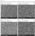
- Example and Comparative Examples 1 and 2 The slurries using the binders of Example and Comparative Examples 1 and 2 were applied to thicknesses of 3, 4, and 5 ⁇ m on a cross-sectional basis at a humidity of 45%, and additionally, 3 ⁇ m coating on a cross-sectional basis was performed at a humidity of 35%.
- the coating surfaces of Example and Comparative Examples 1 and 2 were observed using an electron microscope. The results are shown in FIGS. 2 , 3 and 4 . Good coating was realized only in FIG. 2 , even under conditions of 3 ⁇ m and 35% humidity, and Comparative Example 2 did not exhibit satisfactory coating results under any conditions.
- Example 1 The electrodes were manufactured using the coating compositions of Example and Comparative Examples 1 and 2, and were then measured for ER (resistance, ohms), electrode-separator adhesion (gf/15 mm), and peel strength (gf/15 mm). Only in Example 1, similar properties were exhibited under low humidity and 3 ⁇ m thin-film coating, and adhesion was drastically deteriorated in Comparative Examples 1 and 2. Particularly in Comparative Example 2, adhesion was very low, and was further reduced upon thin-film coating. [Table 1] Conditions Example Comparative Example 1 Comparative Example 2 Humidity (%) Coating thick.
- the present invention can provide a coating composition, including a binder that reinforces the safety due to the strong integration of the separator and the electrode by increasing the bondability between the porous coating layer of the separator and the electrode, suppresses the increase in the interfacial resistance of the separator and the electrode due to electrode side-reactions occurring during a cycle, and improves air permeability.
- the coating composition of the invention can solve problems in which sufficient electrode adhesion cannot be obtained due to drying of the binder before sufficient phase separation, and enables sufficient phase separation even at low humidity of the manufacturing method.
Abstract
Description
- The present invention relates to a coating composition for a lithium secondary battery separator including an adhesive layer, and more particularly to a coating composition for a lithium secondary battery separator including an adhesive layer, suitable for use in coating at least one surface of a porous substrate separator having therein a plurality of pores.
- With the recent trends toward reducing the weight and increasing the functionality of portable devices, such as smartphones, laptop computers, tablet PCs, and portable game machines, the demand for a secondary battery serving as a driving power source thereof is increasing. In the past, nickel-cadmium, nickel-hydrogen, and nickel-zinc batteries have been used, but lithium secondary batteries, which have high operating voltage and high energy density per unit weight, are most frequently used at present.
- Lithium secondary batteries are problematic in that there is a risk of explosion due to the generation of heat depending on the use environment. In order to solve the problem of low safety of the lithium secondary battery, technology for increasing the bondability of a separator, especially a porous coating layer of a separator to an electrode, is receiving attention. Stronger bonding between the separator and the electrode may improve the safety of the battery. It is necessary to develop techniques for a binder that suppresses an increase in interfacial resistance of a separator and an electrode due to electrode side-reactions occurring during a cycle and that improves air permeability and for a separator using the binder.
-
Patent Document 1 discloses a separator including an adhesive layer and a secondary battery using the separator. The secondary battery includes a separator applicable to a secondary battery, and may maintain the shape stability and adhesion of the battery even after charging/discharging under real-world usage conditions of the battery. -
Patent Document 1 pertains to a separator, comprising a porous substrate and an adhesive layer formed on one or both surfaces of the substrate, the adhesive layer including a polyvinylidene fluoride (PVDF)-based first binder containing a vinylidene fluoride-derived unit and 5 wt% or less of a hexafluoropropylene (HFP)-derived unit, and a polyvinylidene fluoride (PVDF)-based second binder containing a vinylidene fluoride-derived unit and a hexafluoropropylene (HFP)-derived unit, the amount of the hexafluoropropylene (HFP)-derived unit being 10 to 30 wt%, the weight ratio of the polyvinylidene fluoride (PVDF)-based first binder and the polyvinylidene fluoride (PVDF)-based second binder being 0.5:9.5 to 2:8, and to a secondary battery including the separator. -
Patent Document 2 pertains to a separator having a binder layer, an electrochemical device including the separator, and a method of manufacturing the separator. In order to solve the problem of low safety of the secondary battery, bondability between a separator, especially a porous coating layer of a separator, and an electrode is enhanced. The safety of the battery is increased through strong bonding of the separator and the electrode, and a binder which suppresses an increase in interfacial resistance of the separator and the electrode due to electrode side-reactions occurring during a cycle and improves air permeability is provided. -
Patent Document 2 provides a separator, comprising a porous substrate, a porous coating layer and a binder layer, in which the binder present in the porous coating layer and the binder layer contains two or more kinds of polyvinylidene fluoride (PVDF) homopolymer or polyvinylidene fluoride-co-hexafluoropropylene (P(VDF-HFP))-based copolymer, the difference in the amount of the hexafluoropropylene (HFP) being 3 wt% or more. Also, a method of manufacturing the separator is provided, the method including forming a binder solution, forming a slurry, and forming a porous coating layer, in which the binder of the binder solution contains two or more kinds of PVDF homopolymer or P(VDF-HFP)-based copolymer, the difference in the amount of HFP being 3 wt% or more. -
Patent Document 3 pertains to a battery cell including a separator having enhanced adhesion, and to a separator, in which even when an organic-inorganic porous coating layer is thinly applied on a porous polymer substrate, high adhesion thereof to the electrode may be exhibited, and the thermal shrinkage ratio of the separator may be improved. -
Patent Document 3 pertains to a battery cell configured such that an electrode assembly comprising a cathode, an anode and a separator interposed between the cathode and the anode is embedded in a battery case, in which the separator includes a porous polymer substrate and an organic-inorganic porous coating layer formed on at least one surface of the porous polymer substrate, in which the organic-inorganic porous coating layer includes inorganic particles, containing a mixture of metal oxide and metal hydroxide, and a mixture of a PVDF-HFP polymer binder ('PHFP high') having high hexafluoropropylene (HFP) content and a PVDF-HFP polymer binder ('PHFP low') having low HFP content, and in which the adhesion of the separator to the cathode or anode is 15 gf/25 mm or more. -
Patent Document 4 pertains to an electrode having enhanced adhesion and a lithium secondary battery including the same, and also provides a method of increasing the cohesion of an electrode current collector and an electrode binder layer and reducing the amount of a binder contained in the electrode binder layer. - In
Patent Document 4, the electrode is configured such that the electrode binder containing an electrode active material is applied on the electrode current collector, and the electrode binder contains a mixture of two or more binders having different specific gravities. - Currently, however, a reduction in the thickness of the secondary battery separator is still required, and in recent years, attempts have been made to thin the binder layer of the separator to 3µm or less (on a cross-sectional basis). Typically, the binder layer of a lithium secondary battery separator is formed in a manner in which a slurry containing a solvent, a binder, a dispersant, and inorganic particles is applied under humidification to thus induce phase separation such that the binder is mainly distributed at the surface of the separator. This process is very sensitive to humidity, and various changes may occur to the type of phase separation depending on the humidity. In some cases, the adhesive layer cannot be sufficiently applied on the surface of the separator.
- Furthermore, when drying is performed before phase separation sufficiently occurs, an adhesive layer cannot be formed on the surface of the separator, and sufficient adhesion cannot be realized. In the case where phase separation is temporarily induced or a binder having a very high phase separation rate is used, the adhesion between the porous substrate and the coating layer and the cohesion between the inorganic particles may deteriorate.
- In particular, when the thickness of the coating layer is reduced from 4µm or more to 3µm, the binder is dried before sufficient phase separation, making it impossible to obtain sufficient electrode adhesion. In the conventional art, upon coating to a thickness of 4µm or more on a cross-sectional basis (
FIG. 1(a) ), the adhesive layer is separated and thus positioned at the surface of the separator, but upon thin-film coating to 3µm or less (FIG. 1(b) ), the adhesive layer is not separated, and thus sufficient adhesion thereof to the electrode is not realized (FIG. 1 ). Even in the conventional art, two or more binders having different PVDF/HPF ratios may be used, as in the present invention, but desired electrode adhesion cannot be attained through sufficient phase separation, both in a humidity environment and upon thin-film coating to 3µm. - (Patent Document 0001) Korean Patent Application Publication No.
10-2016-0117962 - (Patent Document 0002) Korean Patent Application Publication No.
10-2014-0050877 - (Patent Document 0003) Korean Patent Application Publication No.
10-2016-0108116 - (Patent Document 0004) Korean Patent Application Publication No.
10-2013-0117350 - Accordingly, the present invention is intended to provide a coating composition for a separator, which is capable of enhancing the bondability of the porous coating layer of a separator to an electrode. Specifically, the present invention is intended to provide a coating composition for a separator, including a binder that increases battery safety through strong bonding of a separator and an electrode, suppresses an increase in interfacial resistance of a separator and an electrode due to electrode side-reactions occurring during a cycle, and improves air permeability. In particular, when the thickness of the coating layer of the separator is reduced from 4µm to 3µm (on a cross-sectional basis), the coating composition of the invention is able to solve problems in which sufficient electrode adhesion cannot be obtained due to drying of the binder before sufficient phase separation, and enables sufficient phase separation even at low humidity of the manufacturing method.
- Therefore, the present invention provides a coating composition suitable for use in coating at least one surface of a porous substrate having a plurality of pores, the coating composition comprising a solvent, inorganic particles, a dispersant, and a binder, wherein the binder includes a binder B and a binder A, both the binder B and the binder A include a vinylidene fluoride (VDF)-derived unit and a hexafluoropropylene (HFP)-derived unit, the HFP-derived unit constitutes 8 to 50 wt% of the binder B and constitutes 5 wt% or more of the binder A under the condition that a proportion of the HFP-derived unit in the binder A is 80% or less of a proportion of the HFP-derived unit in the binder B, the binder B has a total number average molecular weight of 2 hundred thousand to 2 million, and the binder A has a total number average molecular weight corresponding to 70% or less of that of the binder B, and a weight ratio of the binder A : the binder B in the coating composition is 0.1 to 10 : 1.
- The binder B and the binder A may be composed of vinylidene fluoride (VDF) and hexafluoropropylene (HFP).
- The coating composition may further comprise an additional binder, in addition to the binder B and the binder A, the additional binder including any one or a mixture of two or more selected from the group consisting of a vinylidene fluoride-derived copolymer, including poly(vinylidene fluoride-co-chlorotrifluoroethylene) and poly(vinylidene fluoride-co-trifluoroethylene), polymethyl methacrylate, polyacrylonitrile, polyvinylpyrrolidone, polyvinyl acetate, polyethylene-co-vinyl acetate, polyethylene oxide, cellulose acetate, cellulose acetate butyrate, cellulose acetate propionate, cyanoethyl pullulan, cyanoethyl polyvinyl alcohol, cyanoethyl cellulose, cyanoethyl sucrose, pullulan, carboxyl methyl cellulose, an acrylonitrile-styrene-butadiene copolymer, and polyimide.
- The porous substrate may be a polymer film, a multilayer film thereof, a woven fabric, or a nonwoven fabric, which is formed of any one or a mixture of two or more selected from the group consisting of polyethylene, polypropylene, polyethylene terephthalate, polybutylene terephthalate, polyester, polyacetal, polyamide, polycarbonate, polyimide, polyetheretherketone, polyaryletherketone, polyetherimide, polyamideimide, polybenzimidazole, polyethersulfone, polyphenylene oxide, a cyclic olefin copolymer, polyphenylene sulfide, and polyethylene naphthalene.
- The dispersant may be any one or a mixture of two or more selected from the group consisting of an acrylic copolymer, and the inorganic particles may be selected from the group consisting of inorganic particles having a dielectric constant of 5 or more, inorganic particles having lithium ion transfer capacity, and a mixture thereof.
- The inorganic particles may be composed of at least two kinds of inorganic particles having different sizes. For example, the inorganic particles may include inorganic particles A having D50 of 200 nm to 1µm and inorganic particles B having D50 corresponding to 70% or less of the D50 of the inorganic particles A.
- The binder may be used in an amount of 3 to 50 parts by weight based on 100 parts by weight of the inorganic particles, and the dispersant may be used in an amount of 0.5 to 5 parts by weight based on 100 parts by weight of the inorganic particles.
- In addition, the present invention provides a separator, comprising a coating layer formed through coating with the above coating composition. Here, the coating layer may have a thickness of 3µm or less on a cross-sectional basis.
- In addition, the present invention provides an electrochemical device, comprising a cathode, an anode, and the above separator interposed between the cathode and the anode, and preferably provides a lithium secondary battery.
- In addition, the present invention provides a method of manufacturing a separator, comprising coating at least one surface of a porous substrate having a plurality of pores with the above coating composition under conditions of a humidity ranging from 35 to 45% and a coating thickness of 3µm or less.
-
-
FIG. 1 shows electron microscope images of phenomena occurring upon coating to a thickness of 4µm or more (a) and thin-film coating to a thickness of 3µm or less (b) according to the conventional art; -
FIG. 2 shows electron microscope images of Example according to the present invention; -
FIG. 3 shows electron microscope images of Comparative Example 1 according to the present invention; and -
FIG. 4 shows electron microscope images of Comparative Example 2 according to the present invention. - Hereinafter, a detailed description will be given of the present invention. Prior thereto, it must be understood that the terms or words used in the description and the claims of the present invention are not to be construed limitedly as having typical or dictionary meanings, but should be interpreted as having the meanings and concepts of the invention in keeping with the scope of the invention based on the principle that the inventors can appropriately define the terms in order to describe the invention in the best way. Therefore, the examples described in the present specification are merely preferred embodiments of the present invention, and do not represent all of the technical ideas of the present invention, and thus it is to be understood that a variety of equivalents and modifications able to substitute therefor may be provided at the point of time at which the present invention is filed.
- The present invention addresses a coating composition comprising a solvent, inorganic particles, a dispersant and a binder, suitable for use in coating at least one surface of a porous substrate having a plurality of pores.
- The porous substrate may include, but is not limited to, a polymer film, a multilayer film thereof, a woven fabric, or a nonwoven fabric, which is formed of any one or a mixture of two or more selected from the group consisting of polyethylene, polypropylene, polyethylene terephthalate, polybutylene terephthalate, polyester, polyacetal, polyamide, polycarbonate, polyimide, polyetheretherketone, polyaryletherketone, polyetherimide, polyamideimide, polybenzimidazole, polyethersulfone, polyphenylene oxide, a cyclic olefin copolymer, polyphenylene sulfide, and polyethylene naphthalene.
- The thickness of the porous substrate is not particularly limited, but may fall in the range of about 5 to about 50µm, and the pore size and porosity of the pores in the porous substrate are also not particularly limited, but may range from about 0.01 to about 50µm and from about 10% to about 95%, respectively.
- As the solvent, preferably useful is a solvent having a low boiling point and solubility similar to that of the binder to be used. This enables mixing to be made uniform and the solvent to be easily removed in subsequent procedures. In particular, a polar solvent having a boiling point of less than 100°C is used. However, a non-polar solvent is not desirable, because use of the same entails a concern about decreased dispersibility.
- Non-limiting examples of the solvent may include any one or a mixture of two or more selected from the group consisting of acetone, tetrahydrofuran, methylene chloride, chloroform, dimethylformamide, N-methyl-2-pyrrolidone (NMP), cyclohexane, and water.
- The solvent is used in an amount of about 50 to about 90 parts by weight based on a total of 100 parts by weight of solid and solvent, that is, a total of 100 parts by weight of a solid mixture comprising inorganic material, binder and dispersant and a solvent (e.g. a polar solvent). If the amount of the solvent is less than 50 parts by weight based on the total of 100 parts by weight of the solid and solvent, coating properties are deteriorated due to the high viscosity, great difficulty in forming the binder layer occurs, and it is difficult to form a thin film. On the other hand, if the amount thereof exceeds 90 parts by weight, low productivity and high manufacturing costs may result.
- The inorganic particles are not particularly limited, so long as they are electrochemically stable. In the present invention, the inorganic particles are not particularly limited, so long as they do not cause oxidation and/or reduction reactions in the operating voltage range (e.g. 0 to about 5 V based on Li/Li+) of an electrochemical device. In particular, when inorganic particles having ion transfer capacity are used, the ion conductivity of the electrochemical device may be increased, thus realizing high performance.
- Also, when inorganic particles having a high dielectric constant are used, they may contribute to increasing the dissociation of an electrolyte salt in a liquid electrolyte, for example, a lithium salt, thus improving the ion conductivity of an electrolyte solution.
- Hence, the inorganic particles may include inorganic particles having a high dielectric constant of about 5 or more, for example, about 10 or more, inorganic particles having lithium ion transfer capacity, or mixtures thereof. Non-limiting examples of the inorganic particles having a high dielectric constant of about 5 or more may include BaTiO3, Pb(Zr,Ti)O3 (PZT), Pb1-xLaxZr1-yTiyO3 (PLZT),PB(Mg3Nb2/3)O3-PbTiO3 (PMN-PT), hafnia (HfO2), SrTiO3, SnO2, CeO2, MgO, NiO, CaO, ZnO, ZrO2, Y2O3, Al2O3, TiO2, SiC, Al(OH)3, and mixtures thereof.
- The inorganic particles having lithium ion transfer capacity are inorganic particles in which a lithium element is contained but is not stored, and which have the ability to move lithium ions. Since the inorganic particles having lithium ion transfer capacity may transfer and move lithium ions due to a kind of defect existing in the particle structure, the lithium ion conductivity in the battery is improved and the battery performance may be improved thereby. Non-limiting examples of the inorganic particles having lithium ion transfer capacity may include (LiAlTiP)xOy-based glass (0<x<4, 0<y<13) such as lithium phosphate (Li3PO4), lithium titanium phosphate (LixTiy(PO4)3, 0<x<2, 0<y<3), lithium aluminum titanium phosphate (LixAlyTiz(PO4)3, 0<x<2, 0<y<1, 0<z<3) and 14Li2O-9Al2O3-38TiO2-39P2O5, lithium lanthanum titanate (LixLayTiO3, 0<x<2, 0<y<3), lithium germanium thiophosphate (LixGeyPzSw, 0<x<4, 0<y<1, 0<z<1, 0<w<5) such as Li3.25Ge0.25P0.75S4, lithium nitride (LixNy, 0<x<4, 0<y<2) such as Li3N, SiS2-based glass (LixSiySz, 0<x<3, 0<y<2, 0<z<4) such as Li3PO4-Li2S-SiS2, P2S5-based glass (LixPySz, 0<x<3, 0<y<3, 0<z<7) such as LiI-Li2S-P2S5, and mixtures thereof.
- The size of the inorganic particles is not limited but may fall in the range of about 0.01 to about 10µm, or about 0.05 to about 1.0µm, in order to form a coating layer having a uniform thickness and to achieve appropriate porosity. When the size of the inorganic particles falls within the above range, it is easy to control the properties of the separator due to the improvement in the dispersibility, and also, problems in which mechanical properties may deteriorate due to an increase in the thickness of the porous coating layer or internal shorting may occur upon charging/discharging of the battery due to the excessively large pore size may be prevented. Also, the inorganic particles may be composed of two or more kinds of inorganic particles having different sizes. For example, the inorganic particles may be composed of inorganic particles A having D50 of 200 nm to 1µm and inorganic particles B having D50 corresponding to 70% or less of the D50 of the inorganic particles A.
- The dispersant may be any one or a mixture of two or more selected from the group consisting of an acrylic copolymer. The dispersant exhibits a function as a superior dispersant that improves the dispersibility of an inorganic material. Furthermore, the dispersant has a function as a binder having adhesion, as well as the above function as the dispersant.
- The dispersant contains a polar functional group, which enables interaction with the surface of the inorganic material to thus increase the dispersibility of the inorganic material. Also, the properties of the dispersant may be easily controlled, and it is possible to improve the dispersibility and the adhesion in a balanced manner, thereby contributing to the stability of a separator including the dispersant and an electrochemical device using the separator.
- The acrylic copolymer may be a copolymer containing at least one functional group selected from the group consisting of an OH group, a COOH group, a CN group, an amine group, and an amide group.
- The acrylic copolymer may be a copolymer containing at least one first functional group and at least one second functional group. Here, the first functional group may be selected from the group consisting of an OH group and a COOH group, and the second functional group may be selected from the group consisting of an amine group and an amide group. Here, when the polymer containing an OH group or a COOH group is used alone, adhesion may be enhanced but dispersibility is deteriorated and uniform coating does not occur. On the other hand, when the polymer containing an amine group and/or an amide group is used alone, dispersibility may increase but adhesion to a porous separator substrate may decrease. Thus, when the copolymer containing both at least one first functional group selected from the group consisting of an OH group and a COOH group and at least one second functional group selected from the group consisting of an amine group and an amide group is used, it is possible to realize uniform coating that improves both adhesion and dispersibility in a balanced manner, thereby preventing the coating layer from being stripped and providing electrochemical stability.
- The acrylic copolymer may have a repeating unit derived from a monomer having the first functional group and a repeating unit derived from a monomer having the second functional group.
- Non-limiting examples of the monomer having the first functional group may include at least one selected from the group consisting of (meth)acrylic acid, 2-(meth)acryloyloxy acetic acid, 3-(meth)acryloyloxy propyl acid, 4-(meth)acryloyloxy butyl acid, acrylic acid dimer, itaconic acid, maleic acid, maleic anhydride, 2-hydroxyethyl (meth)acrylate, 2-hydroxypropyl (meth)acrylate, 4-hydroxybutyl (meth)acrylate, 6-hydroxyhexyl (meth)acrylate, 8-hydroxyoctyl (meth)acrylate, 2-hydroxyethyleneglycol (meth)acrylate, and 2-hydroxypropyleneglycol (meth)acrylate.
- The monomer having the second functional group may include those containing at least one of an amine group and an amide group at the side chain thereof, non-limiting examples of which may include at least one selected from the group consisting of 2-(((butoxyamino)carbonyl)oxy)ethyl(meth)acrylate, 2-(diethylamino)ethyl(meth)acrylate, 2-(dimethylamino)ethyl(meth)acrylate, 3-(diethylamino)propyl(meth)acrylate, 3-(dimethylamino)propyl(meth)acrylate, methyl 2-acetoamido(meth)acrylate, 2-(meth)acrylamidoglycolic acid, 2-(meth)acrylamido-2-methyl-1-propane sulfonic acid, (3-(meth)acrylamidopropyl)trimethyl ammonium chloride, N-(meth)acryloylamido-ethoxyethanol, 3-(meth)acryloyl amino-1-propanol, N-(butoxymethyl)(meth)acrylamide, N-tert-butyl(meth)acrylamide, diacetone(meth)acrylamide, N,N-dimethyl(meth)acrylamide, N-(isobutoxymethyl)acrylamide, N-(isopropyl)(meth)acrylamide, (meth)acrylamide, N-phenyl(meth)acrylamide, N-(tris(hydroxymethyl)methyl)(meth)acrylamide, N-N'-(1,3-phenylene)dimaleimide, N-N'-(1,4-phenylene)dimaleimide, N-N'-(1,2-dihydroxyethylene)bisacrylamide, N-N'-ethylenebis(meth)acrylamide, and N-vinylpyrrolidinone.
- Examples of the acrylic copolymer may include, but are not limited to, at least one selected from the group consisting of an ethyl acrylate-acrylic acid-N,N-dimethylacrylamide copolymer, an ethyl acrylate-acrylic acid-2-(dimethylamino)ethyl acrylate copolymer, an ethyl acrylate-acrylic acid-N,N-diethylacrylamide copolymer, and an ethyl acrylate-acrylic acid-2-(diethylamino)ethyl acrylate copolymer.
- The amount of the dispersant may fall in the range of 0.5 to 5 parts by weight based on 100 parts by weight of the inorganic particles.
- The binder includes a binder B and a binder A, and both the binder B and the binder A contain a vinylidene fluoride (VDF)-derived unit and a hexafluoropropylene (HFP)-derived unit. The HFP-derived unit constitutes 8 to 50 wt%, preferably 8 to 40 wt%, more preferably 8 to 30 wt%, much more preferably 8 to 20 wt%, and even more preferably 10 to 15 wt% of the binder B, and constitutes 5 wt% or more of the binder A under the condition that a proportion of the HFP-derived unit in the binder A is 80% or less of a proportion of the HFP-derived unit in the binder B. The total number average molecular weight of the binder B falls in the range of 2 hundred thousand to 2 million, preferably 3 hundred thousand to 1.5 million, more preferably 4 hundred thousand to 1.2 million, and much more preferably 5 hundred thousand to 1 million, and the total number average molecular weight of the binder A is 70% or less of that of the binder B, and the weight ratio of binder A : binder B in the coating composition falls in the range of 0.1 to 10 : 1, preferably 0.3 to 8 : 1, more preferably 0.5 to 6 : 1, much more preferably 0.7 to 4 : 1, and even more preferably 0.8 to 2 : 1. If the amount of the binder A is less than the above lower limit, sufficient electrode adhesion cannot be realized due to drying before phase separation. On the other hand, if the amount of the binder A exceeds the above upper limit, the electrical resistance to the electrode is high or the adhesion deteriorates drastically at a thin coating thickness of 3µm.
- In addition to the binder B and the binder A, an additional binder may be used, and examples thereof may include vinylidene fluoride-derived copolymers including poly(vinylidene fluoride-co-chlorotrifluoroethylene), poly(vinylidene fluoride-co-trifluoroethylene), etc., polymethyl methacrylate, polyacrylonitrile, polyvinylpyrrolidone, polyvinyl acetate, polyethylene-co-vinyl acetate, polyethylene oxide, cellulose acetate, cellulose acetate butyrate, cellulose acetate propionate, cyanoethyl pullulan, cyanoethyl polyvinyl alcohol, cyanoethyl cellulose, cyanoethyl sucrose, pullulan, carboxyl methyl cellulose, an acrylonitrile-styrene-butadiene copolymer, and polyimide, which may be used alone or in combinations of two or more thereof.
- The amount of the binder may fall in the range of 3 to 50 parts by weight based on 100 parts by weight of the inorganic particles.
- The coating method using the coating composition according to the present invention includes the steps of forming a binder solution, forming a coating slurry, and forming a porous coating layer.
- In the step of forming the porous coating layer, the slurry obtained in the step of forming the coating slurry is applied on at least one surface of the porous substrate, thus forming a porous coating layer.
- A description of the porous substrate remains the same as in the separator described above.
- The method of applying the slurry containing inorganic particles dispersed therein on the porous substrate may include a typical coating process that is known in the art, examples of which may include dip coating, die coating, roll coating, comma coating, and mixtures thereof. Also, the porous coating layer may be selectively formed on only one surface or both surfaces of the porous substrate.
- The coating process is preferably performed at predetermined humidity. After coating with the slurry, drying is conducted, whereby the binder A and the binder B according to the present invention dissolved in the coating layer (slurry) have different phase transition properties based on a vapor-induced phase separation phenomenon known in the art. Generally, the phase transition rate by a non-solvent (for example, water or vapor) decreases the phase separation rate in the presence of the same non-solvent with an increase in HFP content, and the amount of the non-solvent necessary for phase separation is relatively increased. Thereby, the binder A, having low HFP content, undergoes phase transition due to a relatively small amount of non-solvent and has a high phase transition rate, and thus the binder A is distributed in a large amount on the surface of the resultant porous coating layer compared to the binder B, ultimately forming the structure of the adhesive layer. On the other hand, the binder B, having relatively high HFP content, requires a large amount of non-solvent for phase separation, and has a relatively low phase separation rate, and thus is present in a large amount in the porous coating layer compared to the binder A. Thus, according to an embodiment of the present invention, a structurally stable porous coating layer is formed, and a binder layer having high adhesion to the electrode is formed on the porous coating layer. When the weight proportion of HFP in the binder A is 80% or less of that of the binder B, desired distribution tendency of the binder as described above may be exhibited.
- However, the desired purpose cannot be achieved based only on the difference in the HFP content under conditions of a thin film of 3µm or less and low humidity. Since the number average molecular weight of the binder A having low HFP content in the binder according to the present invention is lower than that of the binder B, phase transition may occur rapidly, even in the short drying time of the thin-film coating of 3µm or less, and may be carried out at a higher rate. When the number average molecular weight of the binder A is 70% or less of that of the binder B, desired properties may be obtained even under conditions of thin-film coating of 3µm or less and low humidity.
- The drying may be performed by any process known in the art, and may be carried out batchwise or continuously using an oven or a heating chamber in a temperature range set in consideration of the vapor pressure of the solvent used. The drying removes almost all of the solvent present in the slurry, and is preferably conducted as quickly as possible in consideration of productivity, etc. For example, drying may be carried out for 1 min or less, preferably 30 sec or less.
- Thus, the separator of the present invention manufactured by the above manufacturing method may be used as a separator of an electrochemical device.
- Specifically, the separator according to an embodiment of the present invention may be efficiently used as a separator interposed between a cathode and an anode.
- An electrochemical device includes all devices that perform an electrochemical reaction. Specific examples of the electrochemical device may include all kinds of primary batteries, secondary batteries, fuel cells, solar cells, and capacitors such as supercapacitor devices. Particularly, among the secondary batteries, a lithium secondary battery including a lithium metal secondary battery, a lithium ion secondary battery, a lithium polymer secondary battery or a lithium ion polymer secondary battery is preferable.
- The electrochemical device may be manufactured through a method typically known in the art. For example, the electrochemical device may be manufactured by assembling the cathode and the anode with the separator interposed therebetween and then injecting the electrolyte solution.
- The electrode to be applied together with the separator according to an embodiment of the present invention is not particularly limited, and may be manufactured in a manner in which an electrode active material is bound to an electrode current collector using a method typically known in the art. Non-limiting examples of the cathode active material of the electrode active material include a typical cathode active material used for a cathode of an electrochemical device, and particularly, lithium manganese oxide, lithium cobalt oxide, lithium nickel oxide, lithium iron oxide, or lithium composite oxide, as a combination thereof, is preferably used. Non-limiting examples of the anode active material may include a typical anode active material used for an anode of an electrochemical device, and particularly useful is a lithium adsorption material, such as lithium metal or lithium alloy, carbon, petroleum coke, activated carbon, graphite or other carbonaceous materials. Non-limiting examples of the cathode current collector include a foil made of aluminum, nickel or a combination thereof, and non-limiting examples of the anode current collector include a foil made of copper, gold, nickel, a copper alloy or a combination thereof.
- The electrolyte solution that may be used in an embodiment of the present invention may include, but is not limited to, those obtained by dissolving or dissociating a salt having a structure of A+B-, in which A+ includes alkali metal cations such as Li+, Na+, K+ or combinations thereof, and B- includes anions such as PF6 -, BF4 -, Cl-, Br-, I-, ClO4 -, AsF6, CH3CO2 -, CF3SO3 - N(CF3SO2)2 -, C(CF2SO2)3 - or combinations thereof, in an organic solvent including propylene carbonate (PC), ethylene carbonate (EC), diethyl carbonate (DEC), dimethyl carbonate (DMC), dipropyl carbonate (DPC), dimethyl sulfoxide, acetonitrile, dimethoxyethane, diethoxyethane, tetrahydrofuran, N-methyl-2-pyrrolidone (NMP), ethyl methyl carbonate (EMC), gamma-butyrolactone (γ-butyrolactone) or a mixture thereof.
- The electrolyte solution may be injected at an appropriate step during the battery manufacturing process, depending on the manufacturing process of a final product and the properties required thereof.
- A better understanding of the present invention will be given through the following examples and test examples, which are not to be construed as limiting the present invention. The embodiments of the present invention may be modified in a variety of different forms, and the scope of the present invention should not be construed as being limited to the following examples, which are merely provided to fully explain the present invention to those of ordinary skill in the art.
- The binder solutions of Example according to the present invention and Comparative Examples 1 and 2 were prepared as follows.
-
- Binder A: PVDF-HFP, molecular weight of 4 hundred thousand, HFP content of 8%
- Binder B: PVDF-HFP, molecular weight of 9 hundred thousand, HFP content of 14%
- Mixing weight ratio of binder A and binder B at 1:1
- Use of only binder A of Example
- Use of only binder B of Example
- A binder solution was prepared in a manner in which the binder A and the binder B were mixed at a weight ratio of 1:1, added to acetone, and dissolved at 50°C for about 4 hr. As an inorganic material, Al2O3 powder having a size of 500 nm and Al2O3 powder having a size of 250 nm were mixed at a weight ratio of 9:1 and then added to the binder solution such that the weight ratio of polymer binder : total inorganic particles was 1:4. Cyanoethyl polyvinyl alcohol was added in an amount of 10 wt% based on the total amount of PVDF-HFP binder, followed by a ball-milling process for a total of 12 hr, whereby the inorganic particles were pulverized and dispersed, thus preparing a slurry. Here, the ratio of solvent to solid was 4:1.
- The slurries of Comparative Examples 1 and 2 were prepared as above, with the exception that a different binder was used.
- The slurries using the binders of Example and Comparative Examples 1 and 2 were applied to thicknesses of 3, 4, and 5µm on a cross-sectional basis at a humidity of 45%, and additionally, 3µm coating on a cross-sectional basis was performed at a humidity of 35%. The coating surfaces of Example and Comparative Examples 1 and 2 were observed using an electron microscope. The results are shown in
FIGS. 2 ,3 and4 . Good coating was realized only inFIG. 2 , even under conditions of 3µm and 35% humidity, and Comparative Example 2 did not exhibit satisfactory coating results under any conditions. - The electrodes were manufactured using the coating compositions of Example and Comparative Examples 1 and 2, and were then measured for ER (resistance, ohms), electrode-separator adhesion (gf/15 mm), and peel strength (gf/15 mm). Only in Example 1, similar properties were exhibited under low humidity and 3µm thin-film coating, and adhesion was drastically deteriorated in Comparative Examples 1 and 2. Particularly in Comparative Example 2, adhesion was very low, and was further reduced upon thin-film coating.
[Table 1] Conditions Example Comparative Example 1 Comparative Example 2 Humidity (%) Coating thick. (µm) ER (Ohm) Electrode-separator adhesion (gf/15 mm) Peel strength (gf/15 mm) ER (Ohm) Electrode-separator adhesion (gf/15 mm) Peel strength (gf/15 mm) ER (Ohm) Electrode-separator adhesion (gf/15 mm) Peel strength (gf/15 mm) 45 3 0.85 60 153 1.14 52 75 0.83 21 235 45 4 0.92 68 107 1.18 57 89 0.86 27 204 45 5 0.94 75 141 1.26 72 83 0.85 41 216 35 3 0.85 53 164 1.05 7 95 0.82 15 415 - As described above, it can be confirmed that superior properties were exhibited even under conditions of low humidity and thin-film coating only in Example of the present invention.
- The present invention can provide a coating composition, including a binder that reinforces the safety due to the strong integration of the separator and the electrode by increasing the bondability between the porous coating layer of the separator and the electrode, suppresses the increase in the interfacial resistance of the separator and the electrode due to electrode side-reactions occurring during a cycle, and improves air permeability. Upon thin-film coating from 4µm to 3µm, the coating composition of the invention can solve problems in which sufficient electrode adhesion cannot be obtained due to drying of the binder before sufficient phase separation, and enables sufficient phase separation even at low humidity of the manufacturing method.
Claims (13)
- A coating composition, suitable for use in coating at least one surface of a porous substrate having a plurality of pores, the coating composition comprising a solvent, inorganic particles, a dispersant, and a binder,
wherein the binder includes a binder B and a binder A, both the binder B and the binder A include a vinylidene fluoride (VDF)-derived unit and a hexafluoropropylene (HFP)-derived unit,
the HFP-derived unit constitutes 8 to 50 wt% of the binder B, and constitutes 5 wt% or more of the binder A under a condition that a proportion of the HFP-derived unit in the binder A is 80% or less of a proportion of the HFP-derived unit in the binder B,
the binder B has a total number average molecular weight of 2 hundred thousand to 2 million, and the binder A has a total number average molecular weight corresponding to 70% or less of that of the binder B, and
a weight ratio of the binder A : the binder B in the coating composition is 0.1 to 10 : 1. - The coating composition of claim 1, wherein the binder B and the binder A are a copolymer composed of vinylidene fluoride (VDF) and hexafluoropropylene (HFP).
- The coating composition of claim 1, further comprising an additional binder, in addition to the binder B and the binder A, the additional binder including any one or a mixture of two or more selected from the group consisting of a vinylidene fluoride-derived copolymer, including poly(vinylidene fluoride-co-chlorotrifluoroethylene) (PVDF-CTFE) and poly(vinylidene fluoride-co-trifluoroethylene) (PVDF-TFE), polymethyl methacrylate, polyacrylonitrile, polyvinylpyrrolidone, polyvinyl acetate, polyethylene-co-vinyl acetate, polyethylene oxide, cellulose acetate, cellulose acetate butyrate, cellulose acetate propionate, cyanoethyl pullulan, cyanoethyl polyvinyl alcohol, cyanoethyl cellulose, cyanoethyl sucrose, pullulan, carboxyl methyl cellulose, an acrylonitrile-styrene-butadiene copolymer, and polyimide.
- The coating composition of claim 1, wherein the porous substrate is a polymer film, a multilayer film thereof, a woven fabric, or a nonwoven fabric, which is formed of any one or a mixture of two or more selected from the group consisting of polyethylene, polypropylene, polyethylene terephthalate, polybutylene terephthalate, polyester, polyacetal, polyamide, polycarbonate, polyimide, polyetheretherketone, polyaryletherketone, polyetherimide, polyamideimide, polybenzimidazole, polyethersulfone, polyphenylene oxide, a cyclic olefin copolymer, polyphenylene sulfide, and polyethylene naphthalene.
- The coating composition of claim 1, wherein the dispersant is any one or a mixture of two or more selected from the group consisting of an acrylic copolymer.
- The coating composition of claim 1, wherein the inorganic particles are selected from the group consisting of inorganic particles having a dielectric constant of 5 or more, inorganic particles having lithium ion transfer capacity, and a mixture thereof.
- The coating composition of claim 1, wherein the inorganic particles are composed of at least two kinds of inorganic particles having different sizes.
- The coating composition of claim 1, wherein the binder is used in an amount of 3 to 50 parts by weight based on 100 parts by weight of the inorganic particles.
- The coating composition of claim 1, wherein the dispersant is used in an amount of 0.5 to 5 parts by weight based on 100 parts by weight of the inorganic particles.
- A separator, comprising a coating layer formed through coating with the coating composition of any one of claims 1 to 9.
- The separator of claim 10, wherein the coating layer has a thickness of 3µm or less on a cross-sectional basis.
- An electrochemical device, comprising a cathode, an anode, and the separator of claim 10 interposed between the cathode and the anode.
- The electrochemical device of claim 12, wherein the electrochemical device is a lithium secondary battery.
Applications Claiming Priority (2)
| Application Number | Priority Date | Filing Date | Title |
|---|---|---|---|
| KR20170019606 | 2017-02-13 | ||
| PCT/KR2018/001907 WO2018147714A1 (en) | 2017-02-13 | 2018-02-13 | Separation film for lithium secondary battery having adhesive layer |
Publications (3)
| Publication Number | Publication Date |
|---|---|
| EP3518318A1 true EP3518318A1 (en) | 2019-07-31 |
| EP3518318A4 EP3518318A4 (en) | 2019-12-11 |
| EP3518318B1 EP3518318B1 (en) | 2023-12-27 |
Family
ID=63452973
Family Applications (1)
| Application Number | Title | Priority Date | Filing Date |
|---|---|---|---|
| EP18751649.7A Active EP3518318B1 (en) | 2017-02-13 | 2018-02-13 | Separation film for lithium secondary battery having adhesive layer |
Country Status (6)
| Country | Link |
|---|---|
| US (1) | US11721873B2 (en) |
| EP (1) | EP3518318B1 (en) |
| JP (1) | JP6824559B2 (en) |
| KR (1) | KR102311624B1 (en) |
| CN (1) | CN110249447B (en) |
| PL (1) | PL3518318T3 (en) |
Cited By (1)
| Publication number | Priority date | Publication date | Assignee | Title |
|---|---|---|---|---|
| EP3641014A4 (en) * | 2018-01-08 | 2020-12-16 | Lg Chem, Ltd. | Separator for secondary battery, and electrochemical device to which same is applied |
Families Citing this family (7)
| Publication number | Priority date | Publication date | Assignee | Title |
|---|---|---|---|---|
| KR102005870B1 (en) * | 2016-01-15 | 2019-07-31 | 삼성에스디아이 주식회사 | Separator for rechargeable battery and rechargeable battery including the same |
| KR102311810B1 (en) | 2018-09-21 | 2021-10-08 | 주식회사 엘지에너지솔루션 | Separator and electrochemical device containing the same |
| EP3881379A1 (en) * | 2018-11-12 | 2021-09-22 | Fischer Eco Solutions GmbH | Method for bonding two plates together for a fuel cell, especially gluing bipolar plates in a fuel cell |
| CN112020784B (en) | 2018-12-21 | 2023-12-19 | 株式会社Lg新能源 | Separator for electrochemical device and electrochemical device comprising same |
| KR102407048B1 (en) * | 2019-07-04 | 2022-06-08 | 삼성에스디아이 주식회사 | Separator for rechargeable battery and rechargeable lithium battery including the same |
| CN114868301A (en) * | 2019-12-19 | 2022-08-05 | 株式会社Lg新能源 | Membrane for electrochemical device, electrochemical device including the same, and method of manufacturing electrochemical device |
| CN114583163A (en) * | 2020-11-28 | 2022-06-03 | 比亚迪股份有限公司 | Dispersing agent for lithium ion battery, preparation method of dispersing agent, positive electrode slurry, positive plate and lithium ion battery |
Family Cites Families (27)
| Publication number | Priority date | Publication date | Assignee | Title |
|---|---|---|---|---|
| KR100775310B1 (en) * | 2004-12-22 | 2007-11-08 | 주식회사 엘지화학 | Organic/inorganic composite microporous membrane and electrochemical device prepared thereby |
| JP5286844B2 (en) | 2007-03-23 | 2013-09-11 | 住友化学株式会社 | Separator |
| WO2013028046A2 (en) | 2011-08-25 | 2013-02-28 | 주식회사 엘지화학 | Separator having a microcapsule and electrochemical device including same |
| JP5282180B1 (en) | 2011-10-21 | 2013-09-04 | 帝人株式会社 | Non-aqueous secondary battery separator and non-aqueous secondary battery |
| WO2013058368A1 (en) * | 2011-10-21 | 2013-04-25 | 帝人株式会社 | Nonaqueous secondary battery separator and non-aqueous secondary battery |
| CN103947008B (en) | 2011-11-15 | 2017-12-01 | 丰田自动车株式会社 | Nonaqueous electrolyte type secondary cell |
| JP5837437B2 (en) * | 2012-02-07 | 2015-12-24 | 帝人株式会社 | Nonaqueous secondary battery separator and nonaqueous secondary battery |
| KR101514314B1 (en) | 2012-04-18 | 2015-04-22 | 주식회사 엘지화학 | Electrode of Enhanced Adhesive Force and Lithium Secondary Battery Comprising The Same |
| CN103579561B (en) * | 2012-07-25 | 2017-08-15 | 三星Sdi株式会社 | For the dividing plate of lithium rechargeable battery and the lithium rechargeable battery including it |
| KR102218700B1 (en) * | 2012-07-25 | 2021-02-22 | 삼성에스디아이 주식회사 | Separator for rechargeable lithium battery, and rechargeable lithium battery including the same |
| KR20140017742A (en) | 2012-07-31 | 2014-02-12 | 삼성디스플레이 주식회사 | Light guiding plate, manufacturing method thereof and backlight unit including light guiding plate |
| KR101662638B1 (en) | 2012-10-22 | 2016-10-05 | 주식회사 엘지화학 | Separator having binder layer, electrochemical device comprising the separator, and method of preparing the separator |
| JP6110698B2 (en) | 2013-03-19 | 2017-04-05 | 積水化学工業株式会社 | Laminated film, battery separator and battery using the same |
| KR101326229B1 (en) | 2013-10-07 | 2013-11-11 | 고려대학교 산학협력단 | Preparation method for metal nanoparticles using Glyme |
| US10002719B2 (en) | 2014-04-21 | 2018-06-19 | Lg Chem, Ltd. | Separator having binder layer, and electrochemical device comprising the separator and method of preparing the separator |
| KR101841805B1 (en) | 2014-09-17 | 2018-03-23 | 주식회사 엘지화학 | Separator for electrochemical device with porous coating layer and Electrochemical device comprising the same |
| KR20230107896A (en) * | 2014-12-15 | 2023-07-18 | 데이진 가부시키가이샤 | Separator for nonaqueous electrolyte cell, nonaqueous electrolyte cell, and method for manufacturing nonaqueous electrolyte cell |
| KR101551757B1 (en) | 2014-12-30 | 2015-09-10 | 삼성에스디아이 주식회사 | Composition for forming porous heat-resistance layer, separators comprising the porous heat-resistance layer, electrochemical battery using the separator, and method for preparing the separator |
| KR101709697B1 (en) | 2014-12-30 | 2017-02-23 | 삼성에스디아이 주식회사 | Separator for rechargeable lithium battery and rechargeable lithium battery including the same |
| KR101618681B1 (en) | 2014-12-30 | 2016-05-11 | 삼성에스디아이 주식회사 | Composition for forming porous heat-resistance layer, separators comprising the porous heat-resistance layer, electrochemical battery using the separator, and method for preparing the separator |
| KR20160108116A (en) | 2015-03-05 | 2016-09-19 | 주식회사 엘지화학 | Battery Cell Comprising a Separator with Enhanced Adhesive Property |
| KR20160117952A (en) | 2015-04-01 | 2016-10-11 | 박경로 | Golf tee lifting apparatus |
| KR20160117962A (en) * | 2015-04-01 | 2016-10-11 | 삼성에스디아이 주식회사 | Separators comprising bonding layer and secondary battery using the separator |
| WO2016175605A1 (en) | 2015-04-30 | 2016-11-03 | 주식회사 엘지화학 | Separator for electrochemical element having improved electrolyte wettability and electrochemical element comprising same separator |
| KR101674987B1 (en) | 2015-08-06 | 2016-11-10 | 삼성에스디아이 주식회사 | Composition for forming porous heat-resistance layer, separators comprising the porous heat-resistance layer, electrochemical battery using the separator, and method for preparing the separator |
| KR102005870B1 (en) * | 2016-01-15 | 2019-07-31 | 삼성에스디아이 주식회사 | Separator for rechargeable battery and rechargeable battery including the same |
| KR102162403B1 (en) * | 2016-05-17 | 2020-10-06 | 삼성에스디아이 주식회사 | Separator for rechargeable battery and rechargeable lithium battery including the same |
-
2018
- 2018-02-13 US US16/341,805 patent/US11721873B2/en active Active
- 2018-02-13 CN CN201880004178.XA patent/CN110249447B/en active Active
- 2018-02-13 JP JP2019528486A patent/JP6824559B2/en active Active
- 2018-02-13 PL PL18751649.7T patent/PL3518318T3/en unknown
- 2018-02-13 EP EP18751649.7A patent/EP3518318B1/en active Active
- 2018-02-13 KR KR1020180018027A patent/KR102311624B1/en active IP Right Grant
Cited By (2)
| Publication number | Priority date | Publication date | Assignee | Title |
|---|---|---|---|---|
| EP3641014A4 (en) * | 2018-01-08 | 2020-12-16 | Lg Chem, Ltd. | Separator for secondary battery, and electrochemical device to which same is applied |
| US11482758B2 (en) | 2018-01-08 | 2022-10-25 | Lg Energy Solution, Ltd. | Separator including porous polymer substrate, porous coating layer, and resin layer and electrochemical device having the same applied thereto |
Also Published As
| Publication number | Publication date |
|---|---|
| PL3518318T3 (en) | 2024-04-15 |
| KR20180093831A (en) | 2018-08-22 |
| CN110249447A (en) | 2019-09-17 |
| JP2019536242A (en) | 2019-12-12 |
| KR102311624B1 (en) | 2021-10-13 |
| US11721873B2 (en) | 2023-08-08 |
| EP3518318B1 (en) | 2023-12-27 |
| US20190245183A1 (en) | 2019-08-08 |
| CN110249447B (en) | 2022-07-08 |
| EP3518318A4 (en) | 2019-12-11 |
| JP6824559B2 (en) | 2021-02-03 |
Similar Documents
| Publication | Publication Date | Title |
|---|---|---|
| EP3518318B1 (en) | Separation film for lithium secondary battery having adhesive layer | |
| KR102181313B1 (en) | Separator for lithium secondary battery and a method of making the same | |
| US10002719B2 (en) | Separator having binder layer, and electrochemical device comprising the separator and method of preparing the separator | |
| KR101040482B1 (en) | A separator having porous coating layer and electrochemical device containing the same | |
| KR100791791B1 (en) | Electrode having porous active coating layer, and manufacturing method thereof and electrochemical device containing the same | |
| EP2840628B1 (en) | Method for manufacturing separator, separator formed thereby, and electrochemical device comprising said separator | |
| KR20170024574A (en) | A separator for electrochemical device comprising a bonding layer thereon and a electrochemical device comprising the same | |
| KR101662638B1 (en) | Separator having binder layer, electrochemical device comprising the separator, and method of preparing the separator | |
| KR102311810B1 (en) | Separator and electrochemical device containing the same | |
| JP2015092487A (en) | Lithium secondary battery | |
| KR102421619B1 (en) | Separator for -lithium secondary battery and manufacturing method thereof | |
| CN111052450A (en) | Separator for electrochemical device and method of manufacturing the same | |
| US10673045B2 (en) | Secondary battery with improved life characteristics | |
| EP3675227A1 (en) | Separator and electrochemical device comprising same | |
| CN111566843A (en) | Separator for lithium secondary battery having improved adhesion to electrode and resistance characteristics and lithium secondary battery comprising the same | |
| KR20200012802A (en) | Separator and electrochemical device containing the same | |
| KR102421618B1 (en) | Manufacturing method of separator for electrochemical device | |
| KR102019473B1 (en) | A Separator Having an Electrode Bonding Layer and A Cell Assembly Comprising the Same | |
| KR20160136089A (en) | A Separator Having an Electrode Bonding Layer and A Secondary battery Comprising the Same | |
| KR101642334B1 (en) | Separator for secondary battery | |
| KR20130093977A (en) | Separator having porous coating layer, and electrochemical device comprising the same | |
| KR20200102958A (en) | Separator for lithium secondadry battery and manufacturing method thereof | |
| CN112514153A (en) | Porous separator and lithium secondary battery comprising same | |
| KR20160028828A (en) | An organic-inoranic composite porous layer, a seperator and an electrode structure comprising the same | |
| KR102373314B1 (en) | Separator for lithium secondary battery and manufacturing method thereof |
Legal Events
| Date | Code | Title | Description |
|---|---|---|---|
| STAA | Information on the status of an ep patent application or granted ep patent |
Free format text: STATUS: THE INTERNATIONAL PUBLICATION HAS BEEN MADE |
|
| PUAI | Public reference made under article 153(3) epc to a published international application that has entered the european phase |
Free format text: ORIGINAL CODE: 0009012 |
|
| STAA | Information on the status of an ep patent application or granted ep patent |
Free format text: STATUS: REQUEST FOR EXAMINATION WAS MADE |
|
| 17P | Request for examination filed |
Effective date: 20190426 |
|
| AK | Designated contracting states |
Kind code of ref document: A1 Designated state(s): AL AT BE BG CH CY CZ DE DK EE ES FI FR GB GR HR HU IE IS IT LI LT LU LV MC MK MT NL NO PL PT RO RS SE SI SK SM TR |
|
| AX | Request for extension of the european patent |
Extension state: BA ME |
|
| A4 | Supplementary search report drawn up and despatched |
Effective date: 20191113 |
|
| RIC1 | Information provided on ipc code assigned before grant |
Ipc: H01M 10/052 20100101ALI20191107BHEP Ipc: H01M 2/16 20060101AFI20191107BHEP |
|
| DAV | Request for validation of the european patent (deleted) | ||
| DAX | Request for extension of the european patent (deleted) | ||
| STAA | Information on the status of an ep patent application or granted ep patent |
Free format text: STATUS: EXAMINATION IS IN PROGRESS |
|
| 17Q | First examination report despatched |
Effective date: 20210730 |
|
| RAP1 | Party data changed (applicant data changed or rights of an application transferred) |
Owner name: LG ENERGY SOLUTION LTD. |
|
| RAP3 | Party data changed (applicant data changed or rights of an application transferred) |
Owner name: LG ENERGY SOLUTION, LTD. |
|
| REG | Reference to a national code |
Ref country code: DE Ref legal event code: R079 Ref document number: 602018063223 Country of ref document: DE Free format text: PREVIOUS MAIN CLASS: H01M0002160000 Ipc: H01M0050155000 Ref country code: DE Ref legal event code: R079 Ipc: H01M0050155000 |
|
| GRAP | Despatch of communication of intention to grant a patent |
Free format text: ORIGINAL CODE: EPIDOSNIGR1 |
|
| STAA | Information on the status of an ep patent application or granted ep patent |
Free format text: STATUS: GRANT OF PATENT IS INTENDED |
|
| RIC1 | Information provided on ipc code assigned before grant |
Ipc: H01M 10/052 20100101ALI20230731BHEP Ipc: H01M 50/155 20210101AFI20230731BHEP |
|
| INTG | Intention to grant announced |
Effective date: 20230821 |
|
| GRAS | Grant fee paid |
Free format text: ORIGINAL CODE: EPIDOSNIGR3 |
|
| GRAA | (expected) grant |
Free format text: ORIGINAL CODE: 0009210 |
|
| STAA | Information on the status of an ep patent application or granted ep patent |
Free format text: STATUS: THE PATENT HAS BEEN GRANTED |
|
| AK | Designated contracting states |
Kind code of ref document: B1 Designated state(s): AL AT BE BG CH CY CZ DE DK EE ES FI FR GB GR HR HU IE IS IT LI LT LU LV MC MK MT NL NO PL PT RO RS SE SI SK SM TR |
|
| REG | Reference to a national code |
Ref country code: GB Ref legal event code: FG4D |
|
| REG | Reference to a national code |
Ref country code: CH Ref legal event code: EP |
|
| P01 | Opt-out of the competence of the unified patent court (upc) registered |
Effective date: 20231206 |
|
| REG | Reference to a national code |
Ref country code: DE Ref legal event code: R096 Ref document number: 602018063223 Country of ref document: DE |
|
| REG | Reference to a national code |
Ref country code: IE Ref legal event code: FG4D |
|
| REG | Reference to a national code |
Ref country code: SE Ref legal event code: TRGR |
|
| PG25 | Lapsed in a contracting state [announced via postgrant information from national office to epo] |
Ref country code: GR Free format text: LAPSE BECAUSE OF FAILURE TO SUBMIT A TRANSLATION OF THE DESCRIPTION OR TO PAY THE FEE WITHIN THE PRESCRIBED TIME-LIMIT Effective date: 20240328 |
|
| REG | Reference to a national code |
Ref country code: LT Ref legal event code: MG9D |
|
| PG25 | Lapsed in a contracting state [announced via postgrant information from national office to epo] |
Ref country code: LT Free format text: LAPSE BECAUSE OF FAILURE TO SUBMIT A TRANSLATION OF THE DESCRIPTION OR TO PAY THE FEE WITHIN THE PRESCRIBED TIME-LIMIT Effective date: 20231227 |
|
| PGFP | Annual fee paid to national office [announced via postgrant information from national office to epo] |
Ref country code: ES Payment date: 20240319 Year of fee payment: 7 |