EP3518058A1 - Method for automated positioning of a toothed workpiece and production system for carrying out the method - Google Patents
Method for automated positioning of a toothed workpiece and production system for carrying out the method Download PDFInfo
- Publication number
- EP3518058A1 EP3518058A1 EP18153727.5A EP18153727A EP3518058A1 EP 3518058 A1 EP3518058 A1 EP 3518058A1 EP 18153727 A EP18153727 A EP 18153727A EP 3518058 A1 EP3518058 A1 EP 3518058A1
- Authority
- EP
- European Patent Office
- Prior art keywords
- workpiece
- machine
- marking
- cnc
- axis machine
- Prior art date
- Legal status (The legal status is an assumption and is not a legal conclusion. Google has not performed a legal analysis and makes no representation as to the accuracy of the status listed.)
- Granted
Links
- 238000000034 method Methods 0.000 title claims abstract description 50
- 238000004519 manufacturing process Methods 0.000 title claims description 32
- 238000003754 machining Methods 0.000 claims abstract description 10
- 238000001514 detection method Methods 0.000 claims abstract description 9
- 239000000523 sample Substances 0.000 claims description 24
- 239000003550 marker Substances 0.000 claims description 10
- 238000012546 transfer Methods 0.000 claims description 5
- 238000012545 processing Methods 0.000 claims description 3
- 238000005259 measurement Methods 0.000 claims 1
- 238000005520 cutting process Methods 0.000 description 10
- 238000004049 embossing Methods 0.000 description 4
- 238000012937 correction Methods 0.000 description 2
- 238000003780 insertion Methods 0.000 description 2
- 230000037431 insertion Effects 0.000 description 2
- 239000000463 material Substances 0.000 description 2
- 238000003801 milling Methods 0.000 description 2
- 230000006978 adaptation Effects 0.000 description 1
- 230000001419 dependent effect Effects 0.000 description 1
- 238000013461 design Methods 0.000 description 1
- 238000011161 development Methods 0.000 description 1
- 238000005530 etching Methods 0.000 description 1
- 238000000227 grinding Methods 0.000 description 1
- 238000010438 heat treatment Methods 0.000 description 1
- 230000001939 inductive effect Effects 0.000 description 1
- 238000009776 industrial production Methods 0.000 description 1
- 230000001678 irradiating effect Effects 0.000 description 1
- 238000010330 laser marking Methods 0.000 description 1
- 230000003287 optical effect Effects 0.000 description 1
- 238000003860 storage Methods 0.000 description 1
- 238000011144 upstream manufacturing Methods 0.000 description 1
Images


Classifications
-
- B—PERFORMING OPERATIONS; TRANSPORTING
- B23—MACHINE TOOLS; METAL-WORKING NOT OTHERWISE PROVIDED FOR
- B23F—MAKING GEARS OR TOOTHED RACKS
- B23F23/00—Accessories or equipment combined with or arranged in, or specially designed to form part of, gear-cutting machines
- B23F23/12—Other devices, e.g. tool holders; Checking devices for controlling workpieces in machines for manufacturing gear teeth
-
- G—PHYSICS
- G05—CONTROLLING; REGULATING
- G05B—CONTROL OR REGULATING SYSTEMS IN GENERAL; FUNCTIONAL ELEMENTS OF SUCH SYSTEMS; MONITORING OR TESTING ARRANGEMENTS FOR SUCH SYSTEMS OR ELEMENTS
- G05B19/00—Programme-control systems
- G05B19/02—Programme-control systems electric
- G05B19/18—Numerical control [NC], i.e. automatically operating machines, in particular machine tools, e.g. in a manufacturing environment, so as to execute positioning, movement or co-ordinated operations by means of programme data in numerical form
- G05B19/19—Numerical control [NC], i.e. automatically operating machines, in particular machine tools, e.g. in a manufacturing environment, so as to execute positioning, movement or co-ordinated operations by means of programme data in numerical form characterised by positioning or contouring control systems, e.g. to control position from one programmed point to another or to control movement along a programmed continuous path
-
- G—PHYSICS
- G05—CONTROLLING; REGULATING
- G05B—CONTROL OR REGULATING SYSTEMS IN GENERAL; FUNCTIONAL ELEMENTS OF SUCH SYSTEMS; MONITORING OR TESTING ARRANGEMENTS FOR SUCH SYSTEMS OR ELEMENTS
- G05B2219/00—Program-control systems
- G05B2219/30—Nc systems
- G05B2219/36—Nc in input of data, input key till input tape
- G05B2219/36371—Barcode reader
-
- G—PHYSICS
- G05—CONTROLLING; REGULATING
- G05B—CONTROL OR REGULATING SYSTEMS IN GENERAL; FUNCTIONAL ELEMENTS OF SUCH SYSTEMS; MONITORING OR TESTING ARRANGEMENTS FOR SUCH SYSTEMS OR ELEMENTS
- G05B2219/00—Program-control systems
- G05B2219/30—Nc systems
- G05B2219/37—Measurements
- G05B2219/37097—Marker on workpiece to detect reference position
-
- G—PHYSICS
- G05—CONTROLLING; REGULATING
- G05B—CONTROL OR REGULATING SYSTEMS IN GENERAL; FUNCTIONAL ELEMENTS OF SUCH SYSTEMS; MONITORING OR TESTING ARRANGEMENTS FOR SUCH SYSTEMS OR ELEMENTS
- G05B2219/00—Program-control systems
- G05B2219/30—Nc systems
- G05B2219/40—Robotics, robotics mapping to robotics vision
- G05B2219/40538—Barcode reader to detect position
-
- Y—GENERAL TAGGING OF NEW TECHNOLOGICAL DEVELOPMENTS; GENERAL TAGGING OF CROSS-SECTIONAL TECHNOLOGIES SPANNING OVER SEVERAL SECTIONS OF THE IPC; TECHNICAL SUBJECTS COVERED BY FORMER USPC CROSS-REFERENCE ART COLLECTIONS [XRACs] AND DIGESTS
- Y02—TECHNOLOGIES OR APPLICATIONS FOR MITIGATION OR ADAPTATION AGAINST CLIMATE CHANGE
- Y02P—CLIMATE CHANGE MITIGATION TECHNOLOGIES IN THE PRODUCTION OR PROCESSING OF GOODS
- Y02P90/00—Enabling technologies with a potential contribution to greenhouse gas [GHG] emissions mitigation
- Y02P90/02—Total factory control, e.g. smart factories, flexible manufacturing systems [FMS] or integrated manufacturing systems [IMS]
Definitions
- the invention relates to a method for the automated positioning of a toothed workpiece and a manufacturing system for carrying out such a method.
- workpieces are provided with barcodes, QR codes or RFID tags to uniquely identify each individual workpiece and track it along the value chain.
- workpiece-specific data can be assigned to a workpiece that has been acquired during processing or measuring steps.
- workpiece-specific data are used, for example, to correct the process parameters of gear cutting machines. For example, individual workpieces are measured at regular intervals to ensure that the required manufacturing accuracy is maintained. If there is a need for correction, correction values are determined on the basis of the measured data, which are set manually at the Machine itself or via a network to be handed over to the machine control.
- the invention relates to a method for automated positioning of a toothed workpiece, comprising the steps of: providing a toothed workpiece having a machine-readable, workpiece-specific marking, such as a QR code, a bar code, an RFID tag or the like; Attaching the toothed workpiece to a spindle of a CNC controlled multi-axis machine; Automated detection of the marking of the workpiece; Determining an actual position of the workpiece relative to the multi-axis machine based on the marking; Transferring the workpiece from the actual position to a desired position relative to the multi-axis machine before a machining and / or measuring method is performed in the multi-axis machine.
- a machine-readable, workpiece-specific marking such as a QR code, a bar code, an RFID tag or the like
- the workpiece-specific marking therefore serves both to identify the workpiece and to position the workpiece.
- the position of the QR code on the workpiece is therefore a geometric reference mark for positioning the workpiece within the machine.
- a geometric referencing using the workpiece-specific marking in particular allows a workpiece-specific assignment and use of real-time process data for current and / or subsequent manufacturing steps.
- the automated detection of the mark comprises at least the determination of the position of the mark relative to the CNC-controlled multi-axis machine. It may additionally include reading encoded information for workpiece identification.
- the coded information of the tag may be a one-to-one tag in the sense of a unique identifier (UID).
- UID unique identifier
- the toothed workpiece may be, for example, a spur gear or a bevel gear.
- the marking is made so robust that it reliably withstands a heat treatment of the workpiece, wherein the marking can be formed in particular by a deformation and / or a material removal in the region of a workpiece surface.
- the label may e.g. be prepared as a needle embossing on the workpiece.
- the marking can be formed by laser marking.
- a barcode or QR code remains intact throughout the entire production chain.
- the provision of the toothed workpiece merely means the feeding of the workpiece already provided with a marking to the CNC-controlled multi-axis machine, wherein the feeding can take place manually or automatically.
- a further embodiment of the method is characterized by the provision of the toothed workpiece, with the method steps: provision of the machine-readable workpiece-specific marking on the workpiece; Production of a reference geometry, such as a tooth gap, a tooth flank or the like, by intermeshing a workpiece blank; Determining a distance between the mark and the reference geometry of the toothed workpiece; and storing the distance in a workpiece specific record of a database; being the distance is vectorially detected relative to a machine coordinate system of the multi-axis machine and stored in the data record.
- providing the toothed workpiece includes geometrically referencing the toothed workpiece by attaching the marker to the workpiece and storing the distance of that marker to a reference geometry in the database. In subsequent production steps or measuring steps, this geometric reference can be used to enable automated alignment or positioning of the workpiece.
- the provision of the toothed workpiece can in particular include the pre-toothing and the storage of the geometric referencing in a database, which can be used in subsequent production steps or measuring steps.
- the manufacturing of the reference geometry can basically be done before or after the provision of the machine-readable, workpiece-specific marking on the workpiece.
- the provision of the machine-readable, workpiece-specific marking on the workpiece preferably takes place before the production of the reference geometry.
- the marking may be applied to the workpiece or to an untoothed blank (for example after a turning operation) and a toothing may be produced in a subsequent method step.
- the distance between the marking and, for example, the first generated tooth gap can be measured and stored.
- the position of a tooth gap, in particular of the first tooth gap, relative to the marking can already be predefined by the process kinematics stored in the machine control prior to manufacturing the tooth gap, so that an additional measuring of the distance can be dispensed with. This is particularly advantageous for the case that the production of the marking and the (pre-) gear teeth of the workpiece take place on a clamping in a CNC-controlled multi-axis machine.
- the marking on an untoothed workpiece takes place even before the workpiece is fed on a gear cutting machine.
- the tag and database can be used to verify that the correct machine kinematics for the blank in question are loaded in the machine control, loaded process kinematics from the tag and database, and the blank used to produce the blank first tooth space to be positioned.
- a toothing of the workpiece or of an untoothed blank can take place, wherein after the toothing the marking is produced or applied.
- the marking can be produced in such a way that, as viewed along a radial direction, the marking is arranged in alignment with a tooth gap, which may in particular be the first tooth gap produced on the workpiece.
- the marking is basically applied to the first tooth gap and is aligned with the first tooth gap, it is possible to dispense with a workpiece-individual detection of a distance of the marking from the first gap.
- the attachment of the toothed workpiece to the spindle can be done by manually inserting the workpiece in a CNC-controlled multi-axis machine.
- the toothed workpiece which has the machine-readable, workpiece-specific marking, for example manually on a spindle a gear measuring machine are placed.
- the gear measuring machine detects the position of the workpiece-specific marking and the encoded information formed as a QR code, for example. Based on the workpiece-specific marking, which serves as a geometric reference, the toothed workpiece from the actual position can be transferred to the desired position, for example, to allow a collision-free threading a probe into a specific tooth gap.
- the attachment of the toothed workpiece may include automated loading of the spindle of the CNC-controlled multi-axis machine, wherein the toothed workpiece is placed on the spindle, for example by means of a handling device, such as a robot or the like.
- the toothed workpiece for example, automatically fed to a hard finishing machine and placed on the spindle of the hard finishing machine.
- the hard finishing machine detects the position of the workpiece specific mark as well as the encoded information formed as a bar code, for example.
- the toothed workpiece can be transferred from the actual position to the desired position, for. allow a collision-free insertion of a grinding or honing tool in a tooth gap.
- the machine-readable, workpiece-specific marking can be provided by means of a laser or needle embossing. This has the advantage that the marking is permanently and not detachably incorporated into the material of the workpiece.
- the machine-readable, workpiece-specific marking can be glued or printed onto the workpiece.
- a cost-effective marking can be achieved, which is optionally detachable again from the workpiece.
- the machine-readable workpiece-specific mark can be attached to the workpiece by etching.
- the reference geometry may be the first tooth gap formed on the workpiece blank.
- the marking can serve for the geometric referencing of the first tooth gap formed on the workpiece, wherein this first tooth gap can be automatically identified and approached in subsequent production steps or measuring steps on the basis of the geometric referencing.
- the reference geometry is a tooth flank limiting the first tooth gap formed on the workpiece blank. This may be, for example, the right-hand tooth flank of the first tooth gap considered in a plan view of the marking.
- the determination of the spacing when providing the toothed workpiece is carried out with the method steps: detecting the position of the machine-readable workpiece-specific marking within a machine coordinate system of the CNC-controlled multi-axis machine; Detecting the position of the reference geometry within the machine coordinate system of the CNC controlled multi-axis machine; and calculating the difference between the position of the reference geometry and the position of the marker.
- the distance may be, for example, a measured relative to a central center axis of the spindle and the workpiece radial distance and / or angular distance.
- a further refinement of the method is characterized by determining an actual position of the workpiece relative to the multi-axis machine on the basis of the marking, with the method steps: reading the marking with a reading device of the CNC-controlled multi-axis machine and loading the workpiece-specific data set from the database into the controller the CNC-controlled multi-axis machine; Measuring the position of the mark within the machine coordinate system of the CNC controlled multi-axis machine using a measuring device of the CNC controlled multi-axis machine; Calculation of Position of the reference geometry within the machine coordinate system of the CNC-controlled multi-axis machine from the measured position of the marking and the distance between the marking and the reference geometry stored in the data record.
- the position of the reference geometry can therefore be closed and the workpiece can be transferred to its desired position. Due to the fact that the geometric referencing for each workpiece can be stored individually in a database, the transfer of a workpiece from its actual position to the desired position can be workpiece-specific. It is therefore not necessary that for each workpiece, the marking must be made, for example, at a fixed radial distance and a fixed angular distance from the reference geometry, as for each workpiece, the individual distance of the marker to a reference geometry in the database can be stored.
- a first workpiece may have a marking which has an angular distance of 30 ° to a first tooth gap of the toothing of the workpiece, while a second workpiece has a marking which is offset at an angular distance of 60 ° to the first tooth gap of this second workpiece is.
- a probing and / or threading of a probe or a machining tool takes place, in particular a probing of the first tooth gap delimiting tooth flank and / or threading a Probe or a machining tool in the first tooth gap.
- a toothed workpiece is to be hard-finished in the context of known manufacturing processes after hardening, it can be provided that the tooth flanks of three tooth gaps are first touched with a measuring probe for so-called threading, centering or inserting a tool in order to detect the influence of hardness distortions. Subsequently, the measured division can be averaged over the three detected gaps.
- a measuring probe for so-called threading, centering or inserting a tool in order to detect the influence of hardness distortions.
- the measured division can be averaged over the three detected gaps.
- a centering or threading of a tool into a tooth gap can now be effected entirely without prior probing, since the position of the first tooth gap is known with sufficient accuracy by the geometric referencing. This is possible in particular with low expected hardness distortions. It can therefore be started much faster with the actual hard finishing.
- a probing of the gap is performed by a probe, but this probing by the probe is much faster, since the position of the first tooth gap by the geometric referencing is known with sufficient accuracy, and the probe can be delivered without the risk of collision in the area of the tooth head with a large feed into the gap.
- a damage to the probe can be reliably prevented.
- a tooth base or a tooth head can serve for the geometric referencing of the workpiece in connection with the marking.
- the positioning of the workpiece based on the marking can only be a first, comparatively coarse alignment of the workpiece, with an accuracy in the range of +/- 0.2 mm. Subsequently, a probing and threading, for example, a probe, done in a known manner.
- a digital camera can be used for reading, for example, a barcode or QR code, and also for detecting the position of the workpiece.
- a subsequent probing and / or threading can be done using the camera a quick first orientation of the workpiece.
- workpiece-specific real-time process data and / or workpiece-specific geometry data are stored in a database by a CNC-controlled multi-axis machine and used to correct the process kinematics of a CNC-controlled multi-axis machine used in a subsequent measuring and / or processing step ,
- a CNC-controlled multi-axis machine used to correct the process kinematics of a CNC-controlled multi-axis machine used in a subsequent measuring and / or processing step
- an automated start-up of a special tooth gap and, on the other hand, an automated individual adaptation of the process parameters for this tooth gap can take place. If, for example, a pitch error resulting from pre-toothing and hardening of the toothing is to be corrected, the fine machining of the toothed workpiece can be adjusted and performed fully automatically with the aid of the data stored in the database.
- the marking could optionally have an arrow-like shape, pointing in the direction of a tooth gap or a tooth of the workpiece, at least in sections.
- the marking in the form of a QR code after pre-cutting is applied in such a way that a corner of a QR code points in the direction of the first tooth space of the toothing.
- This advantage can alternatively or additionally be achieved in that the marking is arranged in the radial direction at least partially aligned with a tooth gap or a tooth of the workpiece.
- the invention relates to a manufacturing system, designed for carrying out the inventive A method, comprising a CNC controlled multi-axis machine having a spindle for receiving a toothed workpiece having a machine-readable, workpiece-specific marking, such as a QR code, a bar code, an RFID tag or the like, comprising a device for automatically detecting the Marking of the workpiece, which has a device for determining an actual position of the workpiece relative to the multi-axis machine based on the marking, and having a device for transferring the workpiece from the actual position to a desired position relative to the multi-axis machine before a machining and / or measuring method are performed in the multi-axis machine.
- a CNC controlled multi-axis machine having a spindle for receiving a toothed workpiece having a machine-readable, workpiece-specific marking, such as a QR code, a bar code, an RFID tag or the like
- a device for automatically detecting the Marking of the workpiece which has a device for determining an
- the manufacturing system according to the invention is therefore adapted to make at least one automated positioning of the armed workpiece using the workpiece-specific marking.
- an automated identification of the equipped workpiece can be made.
- the CNC-controlled multi-axis machine may be, for example, a gear measuring machine or a finishing machine.
- the manufacturing system has another CNC controlled multi-axis machine configured to provide the toothed workpiece and a database for storing workpiece-specific datasets, the CNC-controlled multi-axis machines connected to the database and for loading workpiece-specific data from the database and for storing workpiece-specific data in the database.
- the further CNC-controlled multi-axis machine can be a machine which is connected upstream of a gear measuring machine or a finishing machine in a production chain and which is set up for producing and storing the geometric referencing.
- the CNC controlled multi-axis machine for providing the toothed workpiece may be a pre-cutting machine such as a gear cutting machine or the like.
- This machine may include as an integral part means for providing the machine-readable, have workpiece-specific marking on the workpiece, such as a marking laser or a needle embossing device.
- workpiece-specific marking on the workpiece such as a marking laser or a needle embossing device.
- the determination of the distance between the marking and, for example, a specific tooth or a specific tooth space of the toothing can be camera-based in order to achieve a rapid geometric referencing.
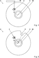
- Fig. 1 and Fig. 2 show by way of example the provision of a workpiece 2.
- the workpiece 2 is according to Fig. 1 initially as an untoothed workpiece 2 without marking, ie as a blank provided.
- the provision of the machine-readable, workpiece-specific marking 4 takes place here before the production of a reference geometry.
- the workpiece 2 is received on a spindle 22 of a CNC controlled multi-axis machine which is a gear cutting machine.
- the marking 4 can also be applied beforehand, while the workpiece 2 is located, for example, on a lathe.
- a marking device 20 produces the QR code 4.
- the marking device 20 in the present case is a marking laser 20.
- the marking device may be a needle embossing device.
- the first tooth gap 6 ( Fig. 2 ) and all other tooth spaces made until the workpiece 2 is fully interlocked ( Fig. 3 ).
- Fig. 2 only the first tooth gap 6 shown, as they can be produced individually initially in a discontinuous Verniermaschine, for example by profile milling with a side milling cutter.
- the production of the first and all further tooth gaps can be effected by means of continuous toothing methods, such as, for example, hobbing.
- Fig. 3 shows the toothed workpiece 2, which has the workpiece-specific, machine-readable marking 4, which is mounted here in the region of an end face.
- the marking 4 is offset by the angle ⁇ to the first tooth gap 6 of the workpiece 2. Furthermore, the marking 4 has a radial distance r1 to a central axis 8 of the workpiece 2.
- the separators r1 and ⁇ may have already been deposited in a database prior to gear cutting, so that the CNC-controlled multi-axis machine produces the first tooth gap 6 on the basis of the position of the marking 4.
- the distances r1 and ⁇ can be recorded digitally using a camera and stored in the database.
- the QR code 4 provides a one-to-one identifier for identifying the workpiece 2 so that the distances r1 and ⁇ stored in the database can be retrieved in subsequent manufacturing steps or measuring steps from the respective CNC-controlled manufacturing devices or measuring devices to automatically automate the workpiece 2 identify and position.
- a camera 12 detects the marker 4, so that the Workpiece 2 is identified and the geometric referencing information is loaded from the database into the control of the gearing measuring machine.
- the camera 12 further determines the actual position of the workpiece 2 relative to a probe 14, the probe 14 being e.g. is to be threaded through a linear movement along a direction Z in the tooth gap 6.
- the control of the gear measuring machine calculates the target position of the workpiece 2 on the basis of the geometric reference data from the database, so that the workpiece 2 is positioned in the presently described case by a rotation about the center axis 8 of the workpiece 2 relative to the probe 14 (FIG. Fig. 6 ).
- the probe 14 can now be inserted by a linear movement along the direction Z in the tooth gap 6.
- the gapping of the probe 14 is in Fig. 6 indicated by the additional, dashed representation of the probe 14 in an inserted position.
- a sensor for example an optical sensor, a capacitive sensor or an inductive sensor
- a sensor can also be used to read the marking 4.
- the machine readable marking 4 may e.g. an area or elements that are visible only in a certain wavelength range. By irradiating the mark 4 with a suitable wavelength, this area or these elements can be made visible to a sensor.
- identifying the workpiece 2 and detecting the machine-readable Mark 4 are performed separately for the purpose of positioning within a multi-axis machine.
Abstract
Verfahren zur automatisierten Positionierung eines verzahnten Werkstücks, mit den Verfahrensschritten:- Bereitstellen eines verzahnten Werkstücks (2), das eine maschinenlesbare, werkstückspezifische Markierung (4) aufweist, wie einen QR-Code, einen Barcode, ein RFID-Tag oder dergleichen;- Anbringen des verzahnten Werkstücks (4) an einer Spindel (10) einer CNCgesteuerten Mehrachsmaschine;- Automatisiertes Erfassen der Markierung (4) des Werkstücks (2);- Ermitteln einer Ist-Position des Werkstücks (2) relativ zu der Mehrachsmaschine anhand der Markierung (4);- Überführen des Werkstücks (2) aus der Ist-Position in eine Soll-Position relativ zu der Mehrachsmaschine bevor ein Bearbeitungs- und/oder Messverfahren in der Mehrachsmaschine durchgeführt wird.Method for the automated positioning of a toothed workpiece, comprising the steps of: providing a toothed workpiece (2) having a machine-readable workpiece-specific marking (4), such as a QR code, a bar code, an RFID tag or the like; the toothed workpiece (4) on a spindle (10) of a CNC-controlled multi-axis machine, - automated detection of the marking (4) of the workpiece (2), determination of an actual position of the workpiece (2) relative to the multi-axis machine on the basis of the marking (4 - Transferring the workpiece (2) from the actual position to a desired position relative to the multi-axis machine before a machining and / or measuring method is performed in the multi-axis machine.
Description
Gegenstand der Erfindung sind ein Verfahren zur automatisierten Positionierung eines verzahnten Werkstücks sowie ein Fertigungssystem zur Durchführung eines solchen Verfahrens.The invention relates to a method for the automated positioning of a toothed workpiece and a manufacturing system for carrying out such a method.
In der industriellen Fertigung werden Werkstücke mit Strichcodes, QR-Codes oder RFID-Tags versehen, um jedes einzelne Werkstück eindeutig zu identifizieren und entlang der Wertschöpfungskette zu verfolgen. Hierbei können einem Werkstück werkstückspezifische Daten zugeordnet werden, die während Bearbeitungs- oder Messschritten erfasst worden sind.In industrial production, workpieces are provided with barcodes, QR codes or RFID tags to uniquely identify each individual workpiece and track it along the value chain. Here, workpiece-specific data can be assigned to a workpiece that has been acquired during processing or measuring steps.
In der Serienfertigung von verzahnten Werkstücken werden werkstückspezifische Daten beispielsweise dazu verwendet, die Prozessparameter von Verzahnmaschinen zu korrigieren. So werden in regelmäßigen Abständen einzelne Werkstücke vermessen, um sicherzustellen, dass die geforderte Fertigungsgenauigkeit eingehalten wird. Sofern ein Korrekturbedarf vorliegt, werden anhand der Messdaten Korrekturwerte ermittelt, die manuell an der Maschine selbst oder über ein Netzwerk an die Maschinensteuerung übergeben werden.In series production of toothed workpieces, workpiece-specific data are used, for example, to correct the process parameters of gear cutting machines. For example, individual workpieces are measured at regular intervals to ensure that the required manufacturing accuracy is maintained. If there is a need for correction, correction values are determined on the basis of the measured data, which are set manually at the Machine itself or via a network to be handed over to the machine control.
Vor dem Hintergrund des Stands der Technik besteht die technische Problemstellung, die geforderte Fertigungsgenauigkeit bei der Herstellung verzahnter Werkstücke möglichst effizient zu erreichen.Against the background of the prior art, there is the technical problem of achieving the required manufacturing accuracy in the production of toothed workpieces as efficiently as possible.
Die voranstehende beschriebene, technische Problemstellung wird jeweils gelöst durch ein Verfahren nach Anspruch 1 und ein Fertigungssystem nach Anspruch 12. Weitere Ausgestaltungen der Erfindung ergeben sich aus den abhängigen Ansprüchen und der nachstehenden Beschreibung.The technical problem described above is solved in each case by a method according to claim 1 and a manufacturing system according to
Gemäß einem ersten Aspekt betrifft die Erfindung ein Verfahren zur automatisierten Positionierung eines verzahnten Werkstücks, mit den Verfahrensschritten: Bereitstellen eines verzahnten Werkstücks, das eine maschinenlesbare, werkstückspezifische Markierung aufweist, wie einen QR-Code, einen Barcode, ein RFID-Tag oder dergleichen; Anbringen des verzahnten Werkstücks an einer Spindel einer CNC-gesteuerten Mehrachsmaschine; Automatisiertes Erfassen der Markierung des Werkstücks; Ermitteln einer Ist-Position des Werkstücks relativ zu der Mehrachsmaschine anhand der Markierung; Überführen des Werkstücks aus der Ist-Position in eine Soll-Position relativ zu der Mehrachsmaschine, bevor ein Bearbeitungs- und/oder Messverfahren in der Mehrachsmaschine durchgeführt wird.According to a first aspect, the invention relates to a method for automated positioning of a toothed workpiece, comprising the steps of: providing a toothed workpiece having a machine-readable, workpiece-specific marking, such as a QR code, a bar code, an RFID tag or the like; Attaching the toothed workpiece to a spindle of a CNC controlled multi-axis machine; Automated detection of the marking of the workpiece; Determining an actual position of the workpiece relative to the multi-axis machine based on the marking; Transferring the workpiece from the actual position to a desired position relative to the multi-axis machine before a machining and / or measuring method is performed in the multi-axis machine.
Die werkstückspezifische Markierung dient daher sowohl zur Identifizierung des Werkstücks als auch zur Positionierung des Werkstücks. Soweit beispielsweise ein QR-Code an dem verzahnten Werkstück vorgesehen ist, ist die Position des QR-Codes an dem Werkstück daher eine geometrische Referenzmarke zur Positionierung des Werkstücks innerhalb der Maschine.The workpiece-specific marking therefore serves both to identify the workpiece and to position the workpiece. For example, as far as a QR code is provided on the toothed workpiece, the position of the QR code on the workpiece is therefore a geometric reference mark for positioning the workpiece within the machine.
Eine geometrische Referenzierung mithilfe der werkstückspezifischen Markierung ermöglicht insbesondere eine werkstückspezifische Zuordnung und Verwendung von Echtzeitprozessdaten für laufende und/oder nachfolgende Fertigungsschritte.A geometric referencing using the workpiece-specific marking in particular allows a workpiece-specific assignment and use of real-time process data for current and / or subsequent manufacturing steps.
Das automatisierte Erfassen der Markierung umfasst mindestens das Bestimmen der Position der Markierung relativ zur CNC-gesteuerten Mehrachsmaschine. Es kann zusätzlich auch das Lesen einer codierten Information zur Werkstückidentifikation umfassen.The automated detection of the mark comprises at least the determination of the position of the mark relative to the CNC-controlled multi-axis machine. It may additionally include reading encoded information for workpiece identification.
Bei der codierten Information der Markierung kann es sich um eine eineindeutige Markierung im Sinne eines Unique Identifiers (UID) handeln.The coded information of the tag may be a one-to-one tag in the sense of a unique identifier (UID).
Bei dem verzahnten Werkstück kann es sich beispielsweise um ein Stirnrad oder ein Kegelrad handeln.The toothed workpiece may be, for example, a spur gear or a bevel gear.
Bevorzugt ist die Markierung derart robust ausgeführt, dass sie einer Wärmebehandlung des Werkstücks zuverlässig standhält, wobei die Markierung insbesondere durch eine Deformation und/oder einen Materialabtrag im Bereich einer Werkstückoberfläche gebildet sein kann. So kann die Markierung z.B. als Nadelprägung an dem Werkstück hergestellt sein. Weiter kann die Markierung durch Lasermarkieren gebildet sein. Demnach bleiben ein Barcode oder QR-Code über die gesamte Fertigungskette hinweg intakt. Gegebenenfalls kann die Markierung selbst nach mehrjähriger Verwendung des fertiggestellten Werkstücks, z.B. in einem Fahrzeuggetriebe, noch lesbar sein.Preferably, the marking is made so robust that it reliably withstands a heat treatment of the workpiece, wherein the marking can be formed in particular by a deformation and / or a material removal in the region of a workpiece surface. Thus, the label may e.g. be prepared as a needle embossing on the workpiece. Furthermore, the marking can be formed by laser marking. As a result, a barcode or QR code remains intact throughout the entire production chain. Optionally, even after several years of use of the finished workpiece, e.g. in a vehicle gearbox, still be readable.
Es kann vorgesehen sein, dass das Bereitstellen des verzahnten Werkstücks lediglich das Zuführen des bereits mit einer Markierung versehenen Werkstücks zu der CNC-gesteuerten Mehrachsmaschine bedeutet, wobei das Zuführen manuell oder automatisiert erfolgen kann.It can be provided that the provision of the toothed workpiece merely means the feeding of the workpiece already provided with a marking to the CNC-controlled multi-axis machine, wherein the feeding can take place manually or automatically.
Alternativ oder ergänzend ist eine weitere Ausgestaltung des Verfahrens gekennzeichnet durch das Bereitstellen des verzahnten Werkstücks, mit den Verfahrensschritten: Vorsehen der maschinenlesbaren, werkstückspezifischen Markierung an dem Werkstück; Fertigung einer Referenzgeometrie, wie einer Zahnlücke, einer Zahnflanke oder dergleichen, durch Verzahnen eines Werkstückrohlings; Bestimmen eines Abstands zwischen der Markierung und der Referenzgeometrie des verzahnten Werkstücks; und Speichern des Abstands in einem werkstückspezifischen Datensatz einer Datenbank; wobei der Abstand bezogen auf ein Maschinenkoordinatensystem der Mehrachsmaschine vektoriell erfasst und in dem Datensatz gespeichert wird.Alternatively or additionally, a further embodiment of the method is characterized by the provision of the toothed workpiece, with the method steps: provision of the machine-readable workpiece-specific marking on the workpiece; Production of a reference geometry, such as a tooth gap, a tooth flank or the like, by intermeshing a workpiece blank; Determining a distance between the mark and the reference geometry of the toothed workpiece; and storing the distance in a workpiece specific record of a database; being the distance is vectorially detected relative to a machine coordinate system of the multi-axis machine and stored in the data record.
In diesem Fall umfasst das Bereitstellen des verzahnten Werkstücks die geometrische Referenzierung des verzahnten Werkstücks, in dem die Markierung an dem Werkstück angebracht wird und der Abstand dieser Markierung zu einer Referenzgeometrie in der Datenbank gespeichert wird. In nachfolgenden Fertigungsschritten oder Messschritten kann auf diese geometrische Referenz zurückgegriffen werden, um ein automatisiertes Ausrichten bzw. Positionieren des Werkstücks zu ermöglichen.In this case, providing the toothed workpiece includes geometrically referencing the toothed workpiece by attaching the marker to the workpiece and storing the distance of that marker to a reference geometry in the database. In subsequent production steps or measuring steps, this geometric reference can be used to enable automated alignment or positioning of the workpiece.
Demnach kann das Bereitstellen und geometrische Referenzieren des verzahnten Werkstücks z.B. mittels einer ersten CNC-gesteuerten Mehrachsmaschine erfolgen, die eine Verzahnungsmaschine oder dergleichen ist.Thus, providing and geometrically referencing the toothed workpiece, e.g. by means of a first CNC-controlled multi-axis machine, which is a gear cutting machine or the like.
Nachfolgend kann das Anbringen des Werkstücks an einer Spindel, das automatisierte Erfassen der Markierung, das Ermitteln einer Ist-Position des Werkstücks und das Überführen aus der Ist-Position in die Soll-Position auf einer zweiten CNC-gesteuerten Mehrachsmaschine erfolgen, die eine Verzahnungsmessmaschine oder eine Feinbearbeitungsmaschine ist.Subsequently, the attachment of the workpiece to a spindle, the automated detection of the marking, determining an actual position of the workpiece and the transfer from the actual position to the desired position on a second CNC-controlled multi-axis machine, which is a gearing or a finishing machine is.
Somit kann das Bereitstellen des verzahnten Werkstücks insbesondere das Vorverzahnen und das Hinterlegen der geometrischen Referenzierung in einer Datenbank umfassen, auf die in darauffolgenden Fertigungsschritten oder Messschritten zurückgegriffen werden kann.Thus, the provision of the toothed workpiece can in particular include the pre-toothing and the storage of the geometric referencing in a database, which can be used in subsequent production steps or measuring steps.
Das Fertigen der Referenzgeometrie kann grundsätzlich vor oder nach dem Vorsehen der maschinenlesbaren, werkstückspezifischen Markierung an dem Werkstück erfolgen. Bevorzugt erfolgt das Vorsehen der maschinenlesbaren, werkstückspezifischen Markierung an dem Werkstück vor der Fertigung der Referenzgeometrie. So kann zunächst die Markierung an dem Werkstück bzw. einem unverzahnten Rohling (z.B. nach einer Drehbearbeitung) angebracht und in einem darauffolgenden Verfahrensschritt eine Verzahnung hergestellt werden.The manufacturing of the reference geometry can basically be done before or after the provision of the machine-readable, workpiece-specific marking on the workpiece. The provision of the machine-readable, workpiece-specific marking on the workpiece preferably takes place before the production of the reference geometry. Thus, firstly, the marking may be applied to the workpiece or to an untoothed blank (for example after a turning operation) and a toothing may be produced in a subsequent method step.
Anschließend können der Abstand zwischen der Markierung und beispielsweise der ersten erzeugten Zahnlücke gemessen und gespeichert werden. Alternativ kann die Position einer Zahnlücke, insbesondere der ersten Zahnlücke, relativ zur Markierung bereits vor dem Fertigen der Zahnlücke durch die in der Maschinensteuerung hinterlegte Prozesskinematik vorgegeben sein, so dass auf ein zusätzliches Messen des Abstands verzichtet werden kann. Dies ist insbesondere für den Fall vorteilhaft, dass das Herstellen der Markierung und das (Vor-)Verzahnen des Werkstücks auf einer Aufspannung in einer CNC-gesteuerten Mehrachsmaschine erfolgen.Subsequently, the distance between the marking and, for example, the first generated tooth gap can be measured and stored. Alternatively, the position of a tooth gap, in particular of the first tooth gap, relative to the marking can already be predefined by the process kinematics stored in the machine control prior to manufacturing the tooth gap, so that an additional measuring of the distance can be dispensed with. This is particularly advantageous for the case that the production of the marking and the (pre-) gear teeth of the workpiece take place on a clamping in a CNC-controlled multi-axis machine.
Es kann vorgesehen sein, dass die Markierung an einem unverzahnten Werkstück, also einem Rohling, bereits vor dem Zuführen des Werkstücks auf einer Verzahnmaschine erfolgt. Sobald dieser markierte Rohling innerhalb einer Verzahnmaschine aufgenommen ist, kann mithilfe der Markierung und der Datenbank überprüft werden, ob die korrekte Maschinenkinematik für den betreffenden Rohling in der Maschinensteuerung geladen ist bzw. anhand der Markierung und der Datenbank eine Prozesskinematik geladen und der Rohling zum Herstellen der ersten Zahnlücke positionieren werden.It can be provided that the marking on an untoothed workpiece, that is to say a blank, takes place even before the workpiece is fed on a gear cutting machine. Once this marked blank is received within a gear cutting machine, the tag and database can be used to verify that the correct machine kinematics for the blank in question are loaded in the machine control, loaded process kinematics from the tag and database, and the blank used to produce the blank first tooth space to be positioned.
Alternativ kann in einem ersten Schritt ein Verzahnen des Werkstücks bzw. eines unverzahnten Rohlings erfolgen, wobei nach dem Verzahnen die Markierung erzeugt oder angebracht wird.Alternatively, in a first step, a toothing of the workpiece or of an untoothed blank can take place, wherein after the toothing the marking is produced or applied.
Insbesondere kann die Markierung in diesem Fall derart hergestellt werden, dass die Markierung entlang einer radialen Richtung betrachtet mit einer Zahnlücke fluchtend angeordnet ist, wobei es sich insbesondere um die erste an dem Werkstück erzeugte Zahnlücke handeln kann.In particular, in this case, the marking can be produced in such a way that, as viewed along a radial direction, the marking is arranged in alignment with a tooth gap, which may in particular be the first tooth gap produced on the workpiece.
Sofern die Vorgabe besteht, dass die Markierung grundsätzlich auf die erste Zahnlücke weisend und mit der ersten Zahnlücke fluchtend appliziert wird, kann auf eine werkstückindividuelle Erfassung eines Abstands der Markierung zur ersten Lücke verzichtet werden.Insofar as the specification exists that the marking is basically applied to the first tooth gap and is aligned with the first tooth gap, it is possible to dispense with a workpiece-individual detection of a distance of the marking from the first gap.
Das Anbringen des verzahnten Werkstücks an der Spindel kann durch manuelles Einlegen des Werkstücks in eine CNC-gesteuerte Mehrachsmaschine erfolgen. So kann das verzahnte Werkstück, das die maschinenlesbare, werkstückspezifische Markierung aufweist, beispielsweise manuell auf eine Spindel einer Verzahnungsmessmaschine aufgesetzt werden. Nachdem das verzahnte Werkstück auf der Spindel aufgenommen ist, erfasst die Verzahnungsmessmaschine die Position der werkstückspezifischen Markierung sowie die beispielsweise als QR-Code ausgebildete, codierte Informationen. Anhand der werkstückspezifischen Markierung, die als geometrische Referenz dient, kann das verzahnte Werkstück aus der Ist-Position in die Soll-Position überführt werden, um z.B. ein kollisionsfreies Einfädeln eines Messtasters in eine bestimmte Zahnlücke zu ermöglichen.The attachment of the toothed workpiece to the spindle can be done by manually inserting the workpiece in a CNC-controlled multi-axis machine. Thus, the toothed workpiece, which has the machine-readable, workpiece-specific marking, for example manually on a spindle a gear measuring machine are placed. After the toothed workpiece is received on the spindle, the gear measuring machine detects the position of the workpiece-specific marking and the encoded information formed as a QR code, for example. Based on the workpiece-specific marking, which serves as a geometric reference, the toothed workpiece from the actual position can be transferred to the desired position, for example, to allow a collision-free threading a probe into a specific tooth gap.
Alternativ kann das Anbringen des verzahnten Werkstücks ein automatisiertes Bestücken der Spindel der CNC-gesteuerten Mehrachsmaschine umfassen, wobei das verzahnte Werkstück beispielsweise mithilfe einer Handhabungseinrichtung, wie einem Roboter oder dergleichen, auf die Spindel aufgesetzt wird. So kann das verzahnte Werkstück beispielsweise automatisiert einer Hartfeinbearbeitungsmaschine zugeführt und auf die Spindel der Hartfeinbearbeitungsmaschine aufgesetzt werden. Anschließend erfasst die Hartfeinbearbeitungsmaschine die Position der werkstückspezifischen Markierung sowie die beispielsweise als Barcode ausgebildete, codierte Informationen. Anhand der werkstückspezifischen Markierung, die als geometrische Referenz dient, kann das verzahnte Werkstück aus der Ist-Position in die Soll-Position überführt werden, um z.B. ein kollisionsfreies Einführen eines Schleif- oder Honwerkzeugs in eine Zahnlücke zu ermöglichen.Alternatively, the attachment of the toothed workpiece may include automated loading of the spindle of the CNC-controlled multi-axis machine, wherein the toothed workpiece is placed on the spindle, for example by means of a handling device, such as a robot or the like. Thus, the toothed workpiece, for example, automatically fed to a hard finishing machine and placed on the spindle of the hard finishing machine. Subsequently, the hard finishing machine detects the position of the workpiece specific mark as well as the encoded information formed as a bar code, for example. On the basis of the workpiece-specific marking, which serves as a geometric reference, the toothed workpiece can be transferred from the actual position to the desired position, for. allow a collision-free insertion of a grinding or honing tool in a tooth gap.
Das Vorsehen der maschinenlesbaren, werkstückspezifischen Markierung kann mithilfe eines Lasers oder durch Nadelprägung erfolgen. Dies hat den Vorteil, dass die Markierung dauerhaft und nicht lösbar in den Werkstoff des Werkstücks eingearbeitet wird.The machine-readable, workpiece-specific marking can be provided by means of a laser or needle embossing. This has the advantage that the marking is permanently and not detachably incorporated into the material of the workpiece.
Alternativ kann die maschinenlesbare, werkstückspezifische Markierung auf das Werkstück aufgeklebt oder aufgedruckt werden. Damit kann eine kostengünstige Markierung erreicht werden, die gegebenenfalls wieder von dem Werkstück ablösbar ist.Alternatively, the machine-readable, workpiece-specific marking can be glued or printed onto the workpiece. Thus, a cost-effective marking can be achieved, which is optionally detachable again from the workpiece.
Alternativ kann die maschinenlesbare, werkstückspezifische Markierung durch Ätzen an dem Werkstück angebracht werden.Alternatively, the machine-readable workpiece-specific mark can be attached to the workpiece by etching.
Nach einer Weiterbildung des voranstehend beschriebenen Verfahrens kann die Referenzgeometrie die erste an dem Werkstückrohling gebildete Zahnlücke sein. Somit kann die Markierung zur geometrischen Referenzierung der ersten an dem Werkstück gebildeten Zahnlücke dienen, wobei diese erste Zahnlücke in nachfolgenden Fertigungsschritten oder Messschritten anhand der geometrischen Referenzierung automatisiert identifiziert und angefahren werden kann.According to a development of the method described above, the reference geometry may be the first tooth gap formed on the workpiece blank. Thus, the marking can serve for the geometric referencing of the first tooth gap formed on the workpiece, wherein this first tooth gap can be automatically identified and approached in subsequent production steps or measuring steps on the basis of the geometric referencing.
Diese Vorteile gelten gleichermaßen für die Alternative, dass die Referenzgeometrie eine Zahnflanke ist, die die erste an dem Werkstückrohling gebildete Zahnlücke begrenzt. Dabei kann es sich beispielsweise um die in einer Draufsicht auf die Markierung betrachtet rechte Zahnflanke der ersten Zahnlücke handeln.These advantages apply equally to the alternative that the reference geometry is a tooth flank limiting the first tooth gap formed on the workpiece blank. This may be, for example, the right-hand tooth flank of the first tooth gap considered in a plan view of the marking.
Nach einer weiteren Ausgestaltung des Verfahrens erfolgt das Bestimmen des Abstands beim Bereitstellen des verzahnten Werkstücks mit den Verfahrensschritten: Erfassen der Position der maschinenlesbaren, werkstückspezifischen Markierung innerhalb eines Maschinenkoordinatensystems der CNC-gesteuerten Mehrachsmaschine; Erfassen der Position der Referenzgeometrie innerhalb des Maschinenkoordinatensystems der CNC-gesteuerten Mehrachsmaschine; und Berechnung der Differenz zwischen der Position der Referenzgeometrie und der Position der Markierung.According to a further embodiment of the method, the determination of the spacing when providing the toothed workpiece is carried out with the method steps: detecting the position of the machine-readable workpiece-specific marking within a machine coordinate system of the CNC-controlled multi-axis machine; Detecting the position of the reference geometry within the machine coordinate system of the CNC controlled multi-axis machine; and calculating the difference between the position of the reference geometry and the position of the marker.
Der Abstand kann beispielsweise ein relativ zu einer zentralen Mittelachse der Spindel und des Werkstücks gemessener radialer Abstand und/oder Winkelabstand sein.The distance may be, for example, a measured relative to a central center axis of the spindle and the workpiece radial distance and / or angular distance.
Eine weitere Ausgestaltung des Verfahrens ist gekennzeichnet durch das Ermitteln einer Ist-Position des Werkstücks relativ zu der Mehrachsmaschine anhand der Markierung, mit den Verfahrensschritten: Lesen der Markierung mit einer Leseeinrichtung der CNC-gesteuerten Mehrachsmaschine und Laden des werkstückspezifischen Datensatzes aus der Datenbank in die Steuerung der CNC-gesteuerten Mehrachsmaschine; Messen der Position der Markierung innerhalb des Maschinenkoordinatensystems der CNC-gesteuerten Mehrachsmaschine mithilfe einer Messeinrichtung der CNC-gesteuerten Mehrachsmaschine; Berechnung der Position der Referenzgeometrie innerhalb des Maschinenkoordinatensystems der CNC-gesteuerten Mehrachsmaschine aus der gemessenen Position der Markierung und dem in dem Datensatz hinterlegten Abstand zwischen der Markierung und der Referenzgeometrie.A further refinement of the method is characterized by determining an actual position of the workpiece relative to the multi-axis machine on the basis of the marking, with the method steps: reading the marking with a reading device of the CNC-controlled multi-axis machine and loading the workpiece-specific data set from the database into the controller the CNC-controlled multi-axis machine; Measuring the position of the mark within the machine coordinate system of the CNC controlled multi-axis machine using a measuring device of the CNC controlled multi-axis machine; Calculation of Position of the reference geometry within the machine coordinate system of the CNC-controlled multi-axis machine from the measured position of the marking and the distance between the marking and the reference geometry stored in the data record.
Sobald die Markierung erfasst ist, kann demnach auf die Position der Referenzgeometrie geschlossen und das Werkstück in seine Sollposition überführt werden. Dadurch, dass die geometrische Referenzierung für jedes Werkstück individuell in einer Datenbank hinterlegt sein kann, kann das Überführen eines Werkstücks aus seiner Ist-Position in die Soll-Position werkstückspezifisch erfolgen. Es ist daher nicht erforderlich, dass für jedes Werkstück die Markierung beispielsweise unter einem fest vorgegebenen radialen Abstand und einem fest vorgegebenen Winkelabstand zur Referenzgeometrie erfolgen muss, da für jedes Werkstück der individuelle Abstand der Markierung zu einer Referenzgeometrie in der Datenbank hinterlegt werden kann. So kann beispielsweise ein erstes Werkstück eine Markierung haben, die einen Winkelabstand von 30° zu einer ersten Zahnlücke der Verzahnung des Werkstücks aufweist, während ein zweites Werkstück eine Markierung aufweist, die unter einem Winkelabstand von 60° zu der ersten Zahnlücke dieses zweiten Werkstücks versetzt angeordnet ist.As soon as the marking is detected, the position of the reference geometry can therefore be closed and the workpiece can be transferred to its desired position. Due to the fact that the geometric referencing for each workpiece can be stored individually in a database, the transfer of a workpiece from its actual position to the desired position can be workpiece-specific. It is therefore not necessary that for each workpiece, the marking must be made, for example, at a fixed radial distance and a fixed angular distance from the reference geometry, as for each workpiece, the individual distance of the marker to a reference geometry in the database can be stored. Thus, for example, a first workpiece may have a marking which has an angular distance of 30 ° to a first tooth gap of the toothing of the workpiece, while a second workpiece has a marking which is offset at an angular distance of 60 ° to the first tooth gap of this second workpiece is.
Es kann vorgesehen sein, dass nach dem Überführen des Werkstücks aus der Ist-Position in die Soll-Position ein Antasten und/oder Einfädeln eines Messtasters oder eines Bearbeitungswerkzeugs erfolgt, wobei insbesondere ein Antasten der die erste Zahnlücke begrenzenden Zahnflanke und/oder ein Einfädeln eines Messtasters oder eines Bearbeitungswerkzeugs in die erste Zahnlücke erfolgen.It can be provided that after the transfer of the workpiece from the actual position to the desired position, a probing and / or threading of a probe or a machining tool takes place, in particular a probing of the first tooth gap delimiting tooth flank and / or threading a Probe or a machining tool in the first tooth gap.
Soweit ein verzahntes Werkstück im Rahmen bekannter Fertigungsverfahren nach einem Härten hartfeinbearbeitet werden soll, kann vorgesehen sein, dass zum sogenannten Einfädeln, Einmitten bzw. Einlücken eines Werkzeugs z.B. die Zahnflanken dreier Zahnlücken zunächst mit einem Messtaster angetastet werden, um den Einfluss von Härteverzügen zu erfassen. Anschließend kann die gemessene Teilung über die drei erfassten Lücken gemittelt werden. Beim Finden einer ersten Lücke durch den Messtaster besteht dabei die Herausforderung, dass auch der Zahnkopf durch den empfindlichen Messtaster getroffen werden kann. Daher werden das Werkstück und der Messtaster langsam angenähert und der Messtaster bei einer Berührung im Bereich des Kopfkegels zurückgezogen. Anschließend wird das Werkstück um eine halbe Teilung verdreht und erneut zugestellt. Das Auffahren auf den Zahnkopf kann trotz größter programmtechnischer Vorsicht zu Verformungen des Messtasters führen.As far as a toothed workpiece is to be hard-finished in the context of known manufacturing processes after hardening, it can be provided that the tooth flanks of three tooth gaps are first touched with a measuring probe for so-called threading, centering or inserting a tool in order to detect the influence of hardness distortions. Subsequently, the measured division can be averaged over the three detected gaps. When finding a first gap through the probe there is the challenge that the tooth tip are hit by the sensitive probe can. Therefore, the workpiece and the probe are slowly approached and the probe is pulled back in contact with the area of the head cone. Subsequently, the workpiece is rotated by half a pitch and delivered again. Driving on the tooth head can lead to deformations of the probe despite the greatest technical caution.
Erfindungsgemäß kann nunmehr ein Einmitten bzw. Einfädeln eines Werkzeugs in eine Zahnlücke gänzlich ohne vorheriges Antasten erfolgen, da die Position der ersten Zahnlücke durch die geometrische Referenzierung hinreichend genau bekannt ist. Dies ist insbesondere bei geringen zu erwartenden Härteverzügen möglich. Es kann daher wesentlich zügiger mit der tatsächlichen Hartfeinbearbeitung begonnen werden.According to the invention, a centering or threading of a tool into a tooth gap can now be effected entirely without prior probing, since the position of the first tooth gap is known with sufficient accuracy by the geometric referencing. This is possible in particular with low expected hardness distortions. It can therefore be started much faster with the actual hard finishing.
Soweit größere Härteverzüge zu erwarten sind, kann vorgesehen sein, dass vor dem Einführen des Werkzeugs in eine Zahnlücke zwar ein Antasten der Lücke durch einen Messtaster erfolgt, dieses Antasten durch den Messtaster jedoch wesentlich zügiger erfolgt, da die Position der ersten Zahnlücke durch die geometrische Referenzierung hinreichend genau bekannt ist, und der Messtaster ohne die Gefahr einer Kollision im Zahnkopfbereich mit großem Vorschub in die Lücke zugestellt werden kann. Auch hier besteht der Vorteil einer verkürzten Prozesszeit im Vergleich zu bekannten Verfahren, wobei zudem ein Beschädigen des Messtasters zuverlässig vermieden werden kann. Neben einer Zahnlücke oder einer Zahnflanke können alternativ oder ergänzend ein Zahnfuß oder ein Zahnkopf zur geometrischen Referenzierung des Werkstücks im Zusammenhang mit der Markierung dienen.As far as greater hardness distortions are to be expected, it can be provided that before the insertion of the tool into a tooth gap a probing of the gap is performed by a probe, but this probing by the probe is much faster, since the position of the first tooth gap by the geometric referencing is known with sufficient accuracy, and the probe can be delivered without the risk of collision in the area of the tooth head with a large feed into the gap. Again, there is the advantage of a shortened process time compared to known methods, in addition, a damage to the probe can be reliably prevented. In addition to a tooth gap or a tooth flank, alternatively or additionally, a tooth base or a tooth head can serve for the geometric referencing of the workpiece in connection with the marking.
Demnach kann das Positionieren des Werkstücks anhand der Markierung lediglich eine erste, vergleichsweise grobe Ausrichtung des Werkstücks sein, mit einer Genauigkeit im Bereich von +/- 0,2 mm. Anschließend kann ein Antasten und Einfädeln, beispielsweise eines Messtasters, in bekannter Weise erfolgen.Accordingly, the positioning of the workpiece based on the marking can only be a first, comparatively coarse alignment of the workpiece, with an accuracy in the range of +/- 0.2 mm. Subsequently, a probing and threading, for example, a probe, done in a known manner.
Es kann vorgesehen sein, dass das automatisierte Erfassen der Markierung und/oder das Ermitteln einer Ist-Position des Werkstücks relativ zu der Mehrachsmaschine anhand der Markierung zumindest teilweise kamerabasiert erfolgen. Eine digitale Kamera kann demnach zum Lesen beispielsweise eines Barcodes oder QR-Codes dienen und zudem auch die Position des Werkstücks erfassen. Insbesondere in Kombination mit einem nachgeschalteten Antasten und/oder Einfädeln kann mithilfe der Kamera eine zügige erste Ausrichtung des Werkstücks erfolgen.It can be provided that the automated detection of the marking and / or the determination of an actual position of the workpiece relative to the multi-axis machine based on the marking at least partially camera-based respectively. Accordingly, a digital camera can be used for reading, for example, a barcode or QR code, and also for detecting the position of the workpiece. In particular, in combination with a subsequent probing and / or threading can be done using the camera a quick first orientation of the workpiece.
Nach einer weiteren Ausgestaltung des Verfahrens kann vorgesehen sein, dass werkstückspezifische Echtzeitprozessdaten und/oder werkstückspezifische Geometriedaten von einer CNC-gesteuerten Mehrachsmaschine in einer Datenbank gespeichert und zur Korrektur der Prozesskinematik einer in einem darauffolgenden Mess- und/oder Bearbeitungsschritt eingesetzten CNC-gesteuerten Mehrachsmaschine verwendet werden. So können mithilfe von in der Datenbank hinterlegten Informationen einerseits ein automatisiertes Anfahren einer speziellen Zahnlücke und andererseits eine automatisierte individuelle Anpassung der Prozessparameter für diese Zahnlücke erfolgen. Soweit beispielsweise ein aus dem Vorverzahnen und Härten resultierender Teilungsfehler der Verzahnung korrigiert werden soll, kann die Feinbearbeitung des verzahnten Werkstücks mithilfe der in der Datenbank hinterlegten Daten vollautomatisch werkstückindividuell angepasst und durchgeführt werden.According to a further embodiment of the method, it can be provided that workpiece-specific real-time process data and / or workpiece-specific geometry data are stored in a database by a CNC-controlled multi-axis machine and used to correct the process kinematics of a CNC-controlled multi-axis machine used in a subsequent measuring and / or processing step , Thus, with the aid of information stored in the database, on the one hand, an automated start-up of a special tooth gap and, on the other hand, an automated individual adaptation of the process parameters for this tooth gap can take place. If, for example, a pitch error resulting from pre-toothing and hardening of the toothing is to be corrected, the fine machining of the toothed workpiece can be adjusted and performed fully automatically with the aid of the data stored in the database.
Um ein manuelles Identifizieren beispielsweise einer ersten Zahnlücke eines verzahnten Werkstücks zu ermöglichen, könnte die Markierung gegebenenfalls eine zumindest abschnittsweise pfeilartige, in Richtung einer Zahnlücke oder eines Zahns des Werkstücks weisende Form haben. Beispielsweise kann festgelegt sein, dass die Markierung in Form eines QR-Codes nach dem Vorverzahnen derart angebracht wird, dass eine Ecke eines QR-Codes in Richtung der ersten Zahnlücke der Verzahnung zeigt.In order to enable a manual identification of, for example, a first tooth gap of a toothed workpiece, the marking could optionally have an arrow-like shape, pointing in the direction of a tooth gap or a tooth of the workpiece, at least in sections. For example, it may be specified that the marking in the form of a QR code after pre-cutting is applied in such a way that a corner of a QR code points in the direction of the first tooth space of the toothing.
Dieser Vorteil kann alternativ oder ergänzend dadurch erreicht werden, dass die Markierung in radialer Richtung betrachtet zumindest abschnittsweise mit einer Zahnlücke oder einem Zahn des Werkstücks fluchtend angeordnet ist.This advantage can alternatively or additionally be achieved in that the marking is arranged in the radial direction at least partially aligned with a tooth gap or a tooth of the workpiece.
Gemäß einem zweiten Aspekt betrifft die Erfindung ein Fertigungssystem, eingerichtet zur Durchführung des erfindungsgemäßen Verfahrens, mit einer CNC-gesteuerten Mehrachsmaschine, die eine Spindel zur Aufnahme eines verzahnten Werkstücks hat, das eine maschinenlesbare, werkstückspezifische Markierung aufweist, wie einen QR-Code, einen Barcode, ein RFID-Tag oder dergleichen, die eine Vorrichtung zum automatisierten Erfassen der Markierung des Werkstücks hat, die eine Vorrichtung zum Ermitteln einer Ist-Position des Werkstücks relativ zu der Mehrachsmaschine anhand der Markierung hat, und die eine Vorrichtung zum Überführen des Werkstücks aus der Ist-Position in eine Soll-Position relativ zu der Mehrachsmaschine hat, bevor ein Bearbeitungs- und/oder Messverfahren in der Mehrachsmaschine durchgeführt werden.According to a second aspect, the invention relates to a manufacturing system, designed for carrying out the inventive A method, comprising a CNC controlled multi-axis machine having a spindle for receiving a toothed workpiece having a machine-readable, workpiece-specific marking, such as a QR code, a bar code, an RFID tag or the like, comprising a device for automatically detecting the Marking of the workpiece, which has a device for determining an actual position of the workpiece relative to the multi-axis machine based on the marking, and having a device for transferring the workpiece from the actual position to a desired position relative to the multi-axis machine before a machining and / or measuring method are performed in the multi-axis machine.
Das erfindungsgemäße Fertigungssystem ist demnach dazu eingerichtet, mithilfe der werkstückspezifischen Markierung mindestens eine automatisierte Positionierung des gerüsteten Werkstücks vorzunehmen. Zusätzlich kann auch eine automatisierte Identifizierung des gerüsteten Werkstücks vorgenommen werden. Bei der CNC-gesteuerten Mehrachsmaschine kann es sich beispielsweise um eine Verzahnungsmessmaschine oder eine Feinbearbeitungsmaschine handeln.The manufacturing system according to the invention is therefore adapted to make at least one automated positioning of the armed workpiece using the workpiece-specific marking. In addition, an automated identification of the equipped workpiece can be made. The CNC-controlled multi-axis machine may be, for example, a gear measuring machine or a finishing machine.
Nach einer weiteren Ausgestaltung hat das Fertigungssystem eine weitere CNC-gesteuerten Mehrachsmaschine, die zum Bereitstellen des verzahnten Werkstücks eingerichtet ist, und eine Datenbank zum Speichern werkstückspezifischer Datensätze, wobei die CNC-gesteuerten Mehrachsmaschinen mit der Datenbank verbunden und zum Laden von werkstückspezifischen Daten aus der Datenbank sowie zum Speichern von werkstückspezifischen Daten in der Datenbank eingerichtet sind.In another embodiment, the manufacturing system has another CNC controlled multi-axis machine configured to provide the toothed workpiece and a database for storing workpiece-specific datasets, the CNC-controlled multi-axis machines connected to the database and for loading workpiece-specific data from the database and for storing workpiece-specific data in the database.
Bei der weiteren CNC-gesteuerten Mehrachsmaschine kann es sich um eine Maschine handeln, die einer Verzahnungsmessmaschine oder einer Feinbearbeitungsmaschine in einer Fertigungskette vorgeschaltet ist und die zum Herstellen und Speichern der geometrischen Referenzierung eingerichtet ist.The further CNC-controlled multi-axis machine can be a machine which is connected upstream of a gear measuring machine or a finishing machine in a production chain and which is set up for producing and storing the geometric referencing.
Die CNC-gesteuerte Mehrachsmaschine zum Bereitstellen des verzahnten Werkstücks kann eine Maschine zum Vorverzahnen sein, wie eine Verzahnungsfräsmaschine oder dergleichen. Diese Maschine kann als integralen Bestandteil eine Einrichtung zum Vorsehen der maschinenlesbaren, werkstückspezifischen Markierung an dem Werkstück haben, wie einen Markierungslaser oder eine Nadelprägeeinrichtung. Auch hier kann das Bestimmen des Abstands zwischen der Markierung und beispielsweise einem bestimmten Zahn oder einer bestimmten Zahnlücke der Verzahnung kamerabasiert erfolgen, um eine zügige geometrische Referenzierung zu erreichen.The CNC controlled multi-axis machine for providing the toothed workpiece may be a pre-cutting machine such as a gear cutting machine or the like. This machine may include as an integral part means for providing the machine-readable, have workpiece-specific marking on the workpiece, such as a marking laser or a needle embossing device. Here, too, the determination of the distance between the marking and, for example, a specific tooth or a specific tooth space of the toothing can be camera-based in order to achieve a rapid geometric referencing.
Nachfolgend wird die Erfindung anhand einer Ausführungsbeispiele darstellenden Zeichnung näher beschrieben.
- Fig. 1
- zeigt schematisch ein unverzahntes Werkstück mit Markierung;
- Fig. 2
- zeigt schematisch das Werkstück aus
Fig. 1 mit einer ersten Zahnlücke; - Fig. 3
- zeigt schematisch das verzahnte Werkstück mit Markierung;
- Fig. 4
- zeigt schematisch die Markierung aus
Fig. 3 ; - Fig. 5
- zeigt schematisch das Werkstück aus
Fig. 3 in einer Ist-Position innerhalb einer Verzahnungsmessmaschine; - Fig. 6
- zeigt schematisch das Werkstück aus
Fig. 3 in einer Soll-Position innerhalb der Verzahnungsmessmaschine ausFig. 5 .
- Fig. 1
- schematically shows an untoothed workpiece with marking;
- Fig. 2
- schematically shows the workpiece
Fig. 1 with a first tooth gap; - Fig. 3
- schematically shows the toothed workpiece with marking;
- Fig. 4
- schematically shows the marker
Fig. 3 ; - Fig. 5
- schematically shows the workpiece
Fig. 3 in an actual position within a gearing measuring machine; - Fig. 6
- schematically shows the workpiece
Fig. 3 in a desired position within the gear measuring machineFig. 5 ,
Das Werkstück 2 wird gemäß
Eine Markierungseinrichtung 20 fertigt den QR-Code 4. Bei der Markierungseinrichtung 20 handelt es sich vorliegend um einen Markierungslaser 20. Gemäß alternativer Ausführungen der Erfindung kann es sich bei der Markierungseinrichtung um eine Nadelprägevorrichtung handeln.A marking
Nach dem Markieren werden die erste Zahnlücke 6 (
Die Abständige r1 und α können bereits vor dem Verzahnen in einer Datenbank hinterlegt worden sein, so dass die CNC-gesteuerte Mehrachsmaschine die erste Zahnlücke 6 anhand der Position der Markierung 4 fertigt. Alternativ oder ergänzend können die Abstände r1 und α mithilfe einer Kamera digital erfasst und in der Datenbank hinterlegt worden sein.The separators r1 and α may have already been deposited in a database prior to gear cutting, so that the CNC-controlled multi-axis machine produces the
Der QR-Code 4 stellt eine eineindeutige Kennung zur Identifizierung des Werkstücks 2 bereit, sodass die in der Datenbank hinterlegten Abstände r1 und α in nachfolgenden Fertigungsschritten oder Messschritten von den jeweiligen CNC-gesteuerten Fertigungseinrichtungen oder Messeinrichtungen abgerufen werden können, um das Werkstück 2 automatisiert zu identifizieren und zu positionieren.The
Vorliegend wird das bereitgestellte Werkstück 2, dessen geometrische Referenzierung in der Datenbank hinterlegt worden ist, nach dem Vorverzahnen und Härten auf einer Spindel 10 einer Verzahnungsmessmaschine angebracht, um das Werkstück 2 zu vermessen (
Mithilfe der Kamera 12 wird weiter die Ist-Position des Werkstücks 2 relativ zu einem Messtaster 14 bestimmt, wobei der Messtaster 14 z.B. durch eine lineare Bewegung entlang einer Richtung Z in die Zahnlücke 6 eingefädelt werden soll.The
Die Steuerung der Verzahnungsmessmaschine berechnet anhand der Daten der geometrischen Referenzierung aus der Datenbank die Soll-Position des Werkstücks 2, sodass das Werkstück 2 in dem vorliegend beschriebenen Fall durch eine Rotation um die Mittelachse 8 des Werkstücks 2 relativ zum Messtaster 14 positioniert wird (
Anschließend erfolgt ein Antasten der die Zahnlücke 6 begrenzenden Zahnflanken 16, 18 durch den Messtaster 14.Subsequently, a probing of the
Je nach Ausgestaltung und Anordnung der maschinenlesbaren Markierung 4, kann statt einer digital arbeitenden Kamera 12 auch ein Sensor (z.B. ein optischer Sensor, ein kapazitiver Sensor oder ein induktiver Sensor) eingesetzt werden, um die Markierung 4 zu lesen.Depending on the design and arrangement of the machine-
Die maschinenlesbare Markierung 4 kann z.B. einen Bereich oder Elemente umfassen, die nur in einem bestimmten Wellenlängenbereich sichtbar werden. Durch Bestrahlen der Markierung 4 mit einer geeigneten Wellenlänge, können dieser Bereich oder diese Elemente für einen Sensor sichtbar gemacht werden.The machine
Bei mindestens einem Teil der Ausführungsformen können somit das Identifizieren des Werkstücks 2 und das Erfassen der maschinenlesbaren Markierung 4 zum Zwecke des Positionierens innerhalb einer Mehrachsmaschine getrennt durchgeführt werden.In at least a portion of the embodiments, thus identifying the
- 22
- Werkstückworkpiece
- 44
- Markierungmark
- 66
- Zahnlückegap
- 88th
- Mittelachsecentral axis
- 1010
- Spindelspindle
- 1212
- Kameracamera
- 1414
- Messtasterprobe
- 1616
- Zahnflanketooth flank
- 1818
- Zahnflanketooth flank
- 2020
- Markierungseinrichtungmarker
- 2222
- Spindelspindle
Claims (15)
oder
or
Priority Applications (2)
| Application Number | Priority Date | Filing Date | Title |
|---|---|---|---|
| EP18153727.5A EP3518058B1 (en) | 2018-01-26 | 2018-01-26 | Method for automated positioning of a toothed workpiece and production system for carrying out the method |
| US16/251,996 US11084111B2 (en) | 2018-01-26 | 2019-01-18 | Method for automated positioning of a toothed workpiece and manufacturing system for carrying out the method |
Applications Claiming Priority (1)
| Application Number | Priority Date | Filing Date | Title |
|---|---|---|---|
| EP18153727.5A EP3518058B1 (en) | 2018-01-26 | 2018-01-26 | Method for automated positioning of a toothed workpiece and production system for carrying out the method |
Publications (2)
| Publication Number | Publication Date |
|---|---|
| EP3518058A1 true EP3518058A1 (en) | 2019-07-31 |
| EP3518058B1 EP3518058B1 (en) | 2021-03-03 |
Family
ID=61189212
Family Applications (1)
| Application Number | Title | Priority Date | Filing Date |
|---|---|---|---|
| EP18153727.5A Active EP3518058B1 (en) | 2018-01-26 | 2018-01-26 | Method for automated positioning of a toothed workpiece and production system for carrying out the method |
Country Status (2)
| Country | Link |
|---|---|
| US (1) | US11084111B2 (en) |
| EP (1) | EP3518058B1 (en) |
Cited By (1)
| Publication number | Priority date | Publication date | Assignee | Title |
|---|---|---|---|---|
| WO2021148147A1 (en) | 2020-01-22 | 2021-07-29 | Reishauer Ag | Method for working a workpiece with two toothings, positioning device for determining a reference rotational angle position of the workpiece and power tool with such a positioning device |
Families Citing this family (1)
| Publication number | Priority date | Publication date | Assignee | Title |
|---|---|---|---|---|
| EP4227045A1 (en) * | 2022-02-11 | 2023-08-16 | JVM Co., Ltd. | Robot arm control system of automated medication dispensing apparatus and control method thereof |
Citations (5)
| Publication number | Priority date | Publication date | Assignee | Title |
|---|---|---|---|---|
| CH682853A5 (en) * | 1990-12-20 | 1993-11-30 | Oerlikon Buehrle Ag | Automatic positioning of gear-wheel tooth gap for numerically controlled gear edge machine - involves using two-edge ball sensor system for recording radial and tangential deflections |
| US20010056313A1 (en) * | 2000-05-08 | 2001-12-27 | Osborne William Joseph | Object locating and retrieving system utilizing labels |
| DE102007043497A1 (en) * | 2007-09-12 | 2009-03-19 | Pepperl + Fuchs Gmbh | Method for aligning an object |
| US20150197009A1 (en) * | 2014-01-10 | 2015-07-16 | Simon Melikian | Method for picking up an article using a robot arm and associated system |
| WO2017074560A1 (en) * | 2015-10-29 | 2017-05-04 | Empire Technology Development Llc | Alignment markers to facilitate detection of object orientation and deformation |
Family Cites Families (16)
| Publication number | Priority date | Publication date | Assignee | Title |
|---|---|---|---|---|
| DE2951605A1 (en) * | 1978-01-07 | 1981-07-09 | Goetze Ag, 5093 Burscheid | METHOD AND DEVICE FOR THE LOCATION-ORIENTED ALIGNMENT OF UNROUND WORKPIECES |
| US4902175A (en) * | 1984-09-12 | 1990-02-20 | Hermann Pfauter Gmbh & Co. | Method and apparatus for determining the angular position of a workpiece and positioning the same |
| KR870001006A (en) * | 1985-07-09 | 1987-03-10 | 노가와 쇼오지 | Method and apparatus for automatically punching printed parts on materials |
| US5292212A (en) * | 1993-04-05 | 1994-03-08 | Caterpillar Inc. | Apparatus for positioning a gear blank |
| DE19631620A1 (en) * | 1996-08-05 | 1998-02-12 | Albert Dick | Alignment errors compensation device e.g. for workpiece on machine tool |
| US6843622B2 (en) * | 2002-02-14 | 2005-01-18 | Concept Design Electronics And Manufacturing, Inc. | Apparatus and method for profiling optical disks |
| US7857021B2 (en) * | 2004-09-09 | 2010-12-28 | Usnr/Kockums Cancar Company | System for positioning a workpiece |
| US20090019697A1 (en) * | 2007-07-16 | 2009-01-22 | Caterpillar Inc. | Method for low lot gear manufacturing |
| EP2192463B1 (en) * | 2008-11-28 | 2014-03-05 | Klingelnberg AG | Device and method to position a symmetrically rotating precision part |
| KR101202320B1 (en) * | 2010-08-11 | 2012-11-16 | 삼성전자주식회사 | Instrumentation system using alignment scope and method for determining system parameters of alignment scope |
| JP2012053509A (en) * | 2010-08-31 | 2012-03-15 | Mitsubishi Heavy Ind Ltd | Numerically controlled machine tool |
| PL2590040T3 (en) * | 2011-11-04 | 2014-08-29 | Nivora Ip B V | Method and device for aiding in manual handling of a work piece during machining |
| US9440313B2 (en) * | 2013-03-12 | 2016-09-13 | Serenity Data Security, Llc | Hard drive data destroying device |
| EP3044735B1 (en) * | 2013-09-12 | 2020-03-04 | Reishauer AG | Rfid identification of metal interchangeable parts for machine tools |
| JP5987073B2 (en) * | 2015-02-12 | 2016-09-06 | ファナック株式会社 | Work positioning device using imaging unit |
| FR3039450B1 (en) * | 2015-07-29 | 2017-08-11 | Airbus Operations Sas | TOOL SUPPORT SYSTEM |
-
2018
- 2018-01-26 EP EP18153727.5A patent/EP3518058B1/en active Active
-
2019
- 2019-01-18 US US16/251,996 patent/US11084111B2/en active Active
Patent Citations (5)
| Publication number | Priority date | Publication date | Assignee | Title |
|---|---|---|---|---|
| CH682853A5 (en) * | 1990-12-20 | 1993-11-30 | Oerlikon Buehrle Ag | Automatic positioning of gear-wheel tooth gap for numerically controlled gear edge machine - involves using two-edge ball sensor system for recording radial and tangential deflections |
| US20010056313A1 (en) * | 2000-05-08 | 2001-12-27 | Osborne William Joseph | Object locating and retrieving system utilizing labels |
| DE102007043497A1 (en) * | 2007-09-12 | 2009-03-19 | Pepperl + Fuchs Gmbh | Method for aligning an object |
| US20150197009A1 (en) * | 2014-01-10 | 2015-07-16 | Simon Melikian | Method for picking up an article using a robot arm and associated system |
| WO2017074560A1 (en) * | 2015-10-29 | 2017-05-04 | Empire Technology Development Llc | Alignment markers to facilitate detection of object orientation and deformation |
Cited By (1)
| Publication number | Priority date | Publication date | Assignee | Title |
|---|---|---|---|---|
| WO2021148147A1 (en) | 2020-01-22 | 2021-07-29 | Reishauer Ag | Method for working a workpiece with two toothings, positioning device for determining a reference rotational angle position of the workpiece and power tool with such a positioning device |
Also Published As
| Publication number | Publication date |
|---|---|
| US20190232406A1 (en) | 2019-08-01 |
| US11084111B2 (en) | 2021-08-10 |
| EP3518058B1 (en) | 2021-03-03 |
Similar Documents
| Publication | Publication Date | Title |
|---|---|---|
| EP1663573B1 (en) | Grinding machine with a concentricity correction system | |
| DE3702594C2 (en) | ||
| DE102017203818B4 (en) | DEVICE FOR AUTOMATIC MEASUREMENT OF THE PRECISION OF A SHAFT FOR AN ENGINE | |
| DE3530576A1 (en) | METHOD AND DEVICE FOR MEASURING A WORKPIECE | |
| DE102014111402A1 (en) | Processing method with a cutting tool and wire electroerosion device | |
| WO2015062717A1 (en) | Method and apparatus for detecting and correcting a spatial position of a workpiece held in a positioning device | |
| DE102012106139A1 (en) | Method for detecting wear in machine tool e.g. machining center for processing workpiece, involves comparing actual state of cutting surface of tool with target state, so as to determine wear size of tool | |
| CH701168B1 (en) | A method and machine for the treatment of workpieces. | |
| EP3724598B1 (en) | Method and device for measuring a roll machining tool | |
| EP0377796A2 (en) | Measuring and alignment device for a cylindrical grinding machine | |
| DE102015201689A1 (en) | Device for laser structuring of hubs of valve train components | |
| EP1356415B1 (en) | Work piece with a machine-readable data carrier | |
| EP3518058B1 (en) | Method for automated positioning of a toothed workpiece and production system for carrying out the method | |
| DE102018101407B4 (en) | Machine tool and method for preparing a machining operation of a cutting rotary tool | |
| DE69733480T2 (en) | Measurement method for a numerically controlled crankpin grinding machine | |
| DE10322762B4 (en) | Holder for a blank and method for measuring the position and orientation of the holder | |
| DE102006039207B3 (en) | System and method for organizing workpieces to be machined | |
| DE3119629A1 (en) | METHOD FOR TENSIONING AND POSITIONING PRECISION PARTS | |
| WO2009030585A1 (en) | Machine tool | |
| DE102012016206A1 (en) | manipulator | |
| DE102012201732A1 (en) | A numerically controlled machine tool and method for controlling an automatic rotational alignment operation of a gear on the machine tool | |
| DE102016109307B4 (en) | Measuring device of a rack, device for bending straightening a rack, method for determining a dimensional deviation of a rack and method for bending straightening a rack | |
| DE19738818B4 (en) | Method and device for the form-controlled superfinishing of a workpiece | |
| DE102008024806B4 (en) | Method for adjusting a profile processing machine for processing wood or wood substitute materials in a continuous process and adjustment system | |
| DE102009039540A1 (en) | processing methods |
Legal Events
| Date | Code | Title | Description |
|---|---|---|---|
| PUAI | Public reference made under article 153(3) epc to a published international application that has entered the european phase |
Free format text: ORIGINAL CODE: 0009012 |
|
| STAA | Information on the status of an ep patent application or granted ep patent |
Free format text: STATUS: REQUEST FOR EXAMINATION WAS MADE |
|
| 17P | Request for examination filed |
Effective date: 20181120 |
|
| AK | Designated contracting states |
Kind code of ref document: A1 Designated state(s): AL AT BE BG CH CY CZ DE DK EE ES FI FR GB GR HR HU IE IS IT LI LT LU LV MC MK MT NL NO PL PT RO RS SE SI SK SM TR |
|
| AX | Request for extension of the european patent |
Extension state: BA ME |
|
| RIN1 | Information on inventor provided before grant (corrected) |
Inventor name: PREDKI, THOMAS |
|
| REG | Reference to a national code |
Ref country code: DE Ref legal event code: R079 Ref document number: 502018004088 Country of ref document: DE Free format text: PREVIOUS MAIN CLASS: G05B0019190000 Ipc: B23F0023120000 |
|
| RIC1 | Information provided on ipc code assigned before grant |
Ipc: B23F 23/12 20060101AFI20200720BHEP Ipc: G05B 19/19 20060101ALI20200720BHEP |
|
| GRAP | Despatch of communication of intention to grant a patent |
Free format text: ORIGINAL CODE: EPIDOSNIGR1 |
|
| STAA | Information on the status of an ep patent application or granted ep patent |
Free format text: STATUS: GRANT OF PATENT IS INTENDED |
|
| INTG | Intention to grant announced |
Effective date: 20200904 |
|
| GRAS | Grant fee paid |
Free format text: ORIGINAL CODE: EPIDOSNIGR3 |
|
| STAA | Information on the status of an ep patent application or granted ep patent |
Free format text: STATUS: GRANT OF PATENT IS INTENDED |
|
| GRAA | (expected) grant |
Free format text: ORIGINAL CODE: 0009210 |
|
| STAA | Information on the status of an ep patent application or granted ep patent |
Free format text: STATUS: THE PATENT HAS BEEN GRANTED |
|
| AK | Designated contracting states |
Kind code of ref document: B1 Designated state(s): AL AT BE BG CH CY CZ DE DK EE ES FI FR GB GR HR HU IE IS IT LI LT LU LV MC MK MT NL NO PL PT RO RS SE SI SK SM TR |
|
| REG | Reference to a national code |
Ref country code: GB Ref legal event code: FG4D Free format text: NOT ENGLISH |
|
| REG | Reference to a national code |
Ref country code: AT Ref legal event code: REF Ref document number: 1366664 Country of ref document: AT Kind code of ref document: T Effective date: 20210315 Ref country code: CH Ref legal event code: EP |
|
| REG | Reference to a national code |
Ref country code: DE Ref legal event code: R096 Ref document number: 502018004088 Country of ref document: DE |
|
| REG | Reference to a national code |
Ref country code: CH Ref legal event code: NV Representative=s name: TROESCH SCHEIDEGGER WERNER AG, CH Ref country code: IE Ref legal event code: FG4D Free format text: LANGUAGE OF EP DOCUMENT: GERMAN |
|
| REG | Reference to a national code |
Ref country code: LT Ref legal event code: MG9D |
|
| PG25 | Lapsed in a contracting state [announced via postgrant information from national office to epo] |
Ref country code: HR Free format text: LAPSE BECAUSE OF FAILURE TO SUBMIT A TRANSLATION OF THE DESCRIPTION OR TO PAY THE FEE WITHIN THE PRESCRIBED TIME-LIMIT Effective date: 20210303 Ref country code: FI Free format text: LAPSE BECAUSE OF FAILURE TO SUBMIT A TRANSLATION OF THE DESCRIPTION OR TO PAY THE FEE WITHIN THE PRESCRIBED TIME-LIMIT Effective date: 20210303 Ref country code: GR Free format text: LAPSE BECAUSE OF FAILURE TO SUBMIT A TRANSLATION OF THE DESCRIPTION OR TO PAY THE FEE WITHIN THE PRESCRIBED TIME-LIMIT Effective date: 20210604 Ref country code: NO Free format text: LAPSE BECAUSE OF FAILURE TO SUBMIT A TRANSLATION OF THE DESCRIPTION OR TO PAY THE FEE WITHIN THE PRESCRIBED TIME-LIMIT Effective date: 20210603 Ref country code: BG Free format text: LAPSE BECAUSE OF FAILURE TO SUBMIT A TRANSLATION OF THE DESCRIPTION OR TO PAY THE FEE WITHIN THE PRESCRIBED TIME-LIMIT Effective date: 20210603 Ref country code: LT Free format text: LAPSE BECAUSE OF FAILURE TO SUBMIT A TRANSLATION OF THE DESCRIPTION OR TO PAY THE FEE WITHIN THE PRESCRIBED TIME-LIMIT Effective date: 20210303 |
|
| REG | Reference to a national code |
Ref country code: NL Ref legal event code: MP Effective date: 20210303 |
|
| PG25 | Lapsed in a contracting state [announced via postgrant information from national office to epo] |
Ref country code: SE Free format text: LAPSE BECAUSE OF FAILURE TO SUBMIT A TRANSLATION OF THE DESCRIPTION OR TO PAY THE FEE WITHIN THE PRESCRIBED TIME-LIMIT Effective date: 20210303 Ref country code: RS Free format text: LAPSE BECAUSE OF FAILURE TO SUBMIT A TRANSLATION OF THE DESCRIPTION OR TO PAY THE FEE WITHIN THE PRESCRIBED TIME-LIMIT Effective date: 20210303 Ref country code: LV Free format text: LAPSE BECAUSE OF FAILURE TO SUBMIT A TRANSLATION OF THE DESCRIPTION OR TO PAY THE FEE WITHIN THE PRESCRIBED TIME-LIMIT Effective date: 20210303 Ref country code: PL Free format text: LAPSE BECAUSE OF FAILURE TO SUBMIT A TRANSLATION OF THE DESCRIPTION OR TO PAY THE FEE WITHIN THE PRESCRIBED TIME-LIMIT Effective date: 20210303 |
|
| PG25 | Lapsed in a contracting state [announced via postgrant information from national office to epo] |
Ref country code: NL Free format text: LAPSE BECAUSE OF FAILURE TO SUBMIT A TRANSLATION OF THE DESCRIPTION OR TO PAY THE FEE WITHIN THE PRESCRIBED TIME-LIMIT Effective date: 20210303 |
|
| PG25 | Lapsed in a contracting state [announced via postgrant information from national office to epo] |
Ref country code: SM Free format text: LAPSE BECAUSE OF FAILURE TO SUBMIT A TRANSLATION OF THE DESCRIPTION OR TO PAY THE FEE WITHIN THE PRESCRIBED TIME-LIMIT Effective date: 20210303 Ref country code: CZ Free format text: LAPSE BECAUSE OF FAILURE TO SUBMIT A TRANSLATION OF THE DESCRIPTION OR TO PAY THE FEE WITHIN THE PRESCRIBED TIME-LIMIT Effective date: 20210303 Ref country code: EE Free format text: LAPSE BECAUSE OF FAILURE TO SUBMIT A TRANSLATION OF THE DESCRIPTION OR TO PAY THE FEE WITHIN THE PRESCRIBED TIME-LIMIT Effective date: 20210303 |
|
| PG25 | Lapsed in a contracting state [announced via postgrant information from national office to epo] |
Ref country code: PT Free format text: LAPSE BECAUSE OF FAILURE TO SUBMIT A TRANSLATION OF THE DESCRIPTION OR TO PAY THE FEE WITHIN THE PRESCRIBED TIME-LIMIT Effective date: 20210705 Ref country code: RO Free format text: LAPSE BECAUSE OF FAILURE TO SUBMIT A TRANSLATION OF THE DESCRIPTION OR TO PAY THE FEE WITHIN THE PRESCRIBED TIME-LIMIT Effective date: 20210303 Ref country code: SK Free format text: LAPSE BECAUSE OF FAILURE TO SUBMIT A TRANSLATION OF THE DESCRIPTION OR TO PAY THE FEE WITHIN THE PRESCRIBED TIME-LIMIT Effective date: 20210303 Ref country code: IS Free format text: LAPSE BECAUSE OF FAILURE TO SUBMIT A TRANSLATION OF THE DESCRIPTION OR TO PAY THE FEE WITHIN THE PRESCRIBED TIME-LIMIT Effective date: 20210703 |
|
| REG | Reference to a national code |
Ref country code: DE Ref legal event code: R097 Ref document number: 502018004088 Country of ref document: DE |
|
| PLBE | No opposition filed within time limit |
Free format text: ORIGINAL CODE: 0009261 |
|
| STAA | Information on the status of an ep patent application or granted ep patent |
Free format text: STATUS: NO OPPOSITION FILED WITHIN TIME LIMIT |
|
| PG25 | Lapsed in a contracting state [announced via postgrant information from national office to epo] |
Ref country code: ES Free format text: LAPSE BECAUSE OF FAILURE TO SUBMIT A TRANSLATION OF THE DESCRIPTION OR TO PAY THE FEE WITHIN THE PRESCRIBED TIME-LIMIT Effective date: 20210303 Ref country code: DK Free format text: LAPSE BECAUSE OF FAILURE TO SUBMIT A TRANSLATION OF THE DESCRIPTION OR TO PAY THE FEE WITHIN THE PRESCRIBED TIME-LIMIT Effective date: 20210303 Ref country code: AL Free format text: LAPSE BECAUSE OF FAILURE TO SUBMIT A TRANSLATION OF THE DESCRIPTION OR TO PAY THE FEE WITHIN THE PRESCRIBED TIME-LIMIT Effective date: 20210303 |
|
| 26N | No opposition filed |
Effective date: 20211206 |
|
| PG25 | Lapsed in a contracting state [announced via postgrant information from national office to epo] |
Ref country code: SI Free format text: LAPSE BECAUSE OF FAILURE TO SUBMIT A TRANSLATION OF THE DESCRIPTION OR TO PAY THE FEE WITHIN THE PRESCRIBED TIME-LIMIT Effective date: 20210303 |
|
| PGFP | Annual fee paid to national office [announced via postgrant information from national office to epo] |
Ref country code: DE Payment date: 20220119 Year of fee payment: 5 Ref country code: CH Payment date: 20220119 Year of fee payment: 5 |
|
| PG25 | Lapsed in a contracting state [announced via postgrant information from national office to epo] |
Ref country code: IS Free format text: LAPSE BECAUSE OF FAILURE TO SUBMIT A TRANSLATION OF THE DESCRIPTION OR TO PAY THE FEE WITHIN THE PRESCRIBED TIME-LIMIT Effective date: 20210703 |
|
| PGFP | Annual fee paid to national office [announced via postgrant information from national office to epo] |
Ref country code: IT Payment date: 20220120 Year of fee payment: 5 |
|
| PG25 | Lapsed in a contracting state [announced via postgrant information from national office to epo] |
Ref country code: MC Free format text: LAPSE BECAUSE OF FAILURE TO SUBMIT A TRANSLATION OF THE DESCRIPTION OR TO PAY THE FEE WITHIN THE PRESCRIBED TIME-LIMIT Effective date: 20210303 |
|
| GBPC | Gb: european patent ceased through non-payment of renewal fee |
Effective date: 20220126 |
|
| REG | Reference to a national code |
Ref country code: BE Ref legal event code: MM Effective date: 20220131 |
|
| PG25 | Lapsed in a contracting state [announced via postgrant information from national office to epo] |
Ref country code: LU Free format text: LAPSE BECAUSE OF NON-PAYMENT OF DUE FEES Effective date: 20220126 Ref country code: GB Free format text: LAPSE BECAUSE OF NON-PAYMENT OF DUE FEES Effective date: 20220126 |
|
| PG25 | Lapsed in a contracting state [announced via postgrant information from national office to epo] |
Ref country code: FR Free format text: LAPSE BECAUSE OF NON-PAYMENT OF DUE FEES Effective date: 20220131 Ref country code: BE Free format text: LAPSE BECAUSE OF NON-PAYMENT OF DUE FEES Effective date: 20220131 |
|
| PG25 | Lapsed in a contracting state [announced via postgrant information from national office to epo] |
Ref country code: IE Free format text: LAPSE BECAUSE OF NON-PAYMENT OF DUE FEES Effective date: 20220126 |
|
| REG | Reference to a national code |
Ref country code: DE Ref legal event code: R119 Ref document number: 502018004088 Country of ref document: DE |
|
| REG | Reference to a national code |
Ref country code: CH Ref legal event code: PL |
|
| PG25 | Lapsed in a contracting state [announced via postgrant information from national office to epo] |
Ref country code: LI Free format text: LAPSE BECAUSE OF NON-PAYMENT OF DUE FEES Effective date: 20230131 Ref country code: DE Free format text: LAPSE BECAUSE OF NON-PAYMENT OF DUE FEES Effective date: 20230801 Ref country code: CH Free format text: LAPSE BECAUSE OF NON-PAYMENT OF DUE FEES Effective date: 20230131 |
|
| PG25 | Lapsed in a contracting state [announced via postgrant information from national office to epo] |
Ref country code: IT Free format text: LAPSE BECAUSE OF NON-PAYMENT OF DUE FEES Effective date: 20230126 |
|
| REG | Reference to a national code |
Ref country code: AT Ref legal event code: MM01 Ref document number: 1366664 Country of ref document: AT Kind code of ref document: T Effective date: 20230126 |