EP3518031A1 - Imaging device - Google Patents
Imaging device Download PDFInfo
- Publication number
- EP3518031A1 EP3518031A1 EP17852687.7A EP17852687A EP3518031A1 EP 3518031 A1 EP3518031 A1 EP 3518031A1 EP 17852687 A EP17852687 A EP 17852687A EP 3518031 A1 EP3518031 A1 EP 3518031A1
- Authority
- EP
- European Patent Office
- Prior art keywords
- imaging unit
- support
- mounting direction
- supported
- bracket
- Prior art date
- Legal status (The legal status is an assumption and is not a legal conclusion. Google has not performed a legal analysis and makes no representation as to the accuracy of the status listed.)
- Granted
Links
Images







Classifications
-
- B—PERFORMING OPERATIONS; TRANSPORTING
- B60—VEHICLES IN GENERAL
- B60R—VEHICLES, VEHICLE FITTINGS, OR VEHICLE PARTS, NOT OTHERWISE PROVIDED FOR
- B60R11/00—Arrangements for holding or mounting articles, not otherwise provided for
- B60R11/04—Mounting of cameras operative during drive; Arrangement of controls thereof relative to the vehicle
-
- G—PHYSICS
- G03—PHOTOGRAPHY; CINEMATOGRAPHY; ANALOGOUS TECHNIQUES USING WAVES OTHER THAN OPTICAL WAVES; ELECTROGRAPHY; HOLOGRAPHY
- G03B—APPARATUS OR ARRANGEMENTS FOR TAKING PHOTOGRAPHS OR FOR PROJECTING OR VIEWING THEM; APPARATUS OR ARRANGEMENTS EMPLOYING ANALOGOUS TECHNIQUES USING WAVES OTHER THAN OPTICAL WAVES; ACCESSORIES THEREFOR
- G03B17/00—Details of cameras or camera bodies; Accessories therefor
- G03B17/02—Bodies
-
- G—PHYSICS
- G03—PHOTOGRAPHY; CINEMATOGRAPHY; ANALOGOUS TECHNIQUES USING WAVES OTHER THAN OPTICAL WAVES; ELECTROGRAPHY; HOLOGRAPHY
- G03B—APPARATUS OR ARRANGEMENTS FOR TAKING PHOTOGRAPHS OR FOR PROJECTING OR VIEWING THEM; APPARATUS OR ARRANGEMENTS EMPLOYING ANALOGOUS TECHNIQUES USING WAVES OTHER THAN OPTICAL WAVES; ACCESSORIES THEREFOR
- G03B17/00—Details of cameras or camera bodies; Accessories therefor
- G03B17/56—Accessories
-
- G—PHYSICS
- G03—PHOTOGRAPHY; CINEMATOGRAPHY; ANALOGOUS TECHNIQUES USING WAVES OTHER THAN OPTICAL WAVES; ELECTROGRAPHY; HOLOGRAPHY
- G03B—APPARATUS OR ARRANGEMENTS FOR TAKING PHOTOGRAPHS OR FOR PROJECTING OR VIEWING THEM; APPARATUS OR ARRANGEMENTS EMPLOYING ANALOGOUS TECHNIQUES USING WAVES OTHER THAN OPTICAL WAVES; ACCESSORIES THEREFOR
- G03B17/00—Details of cameras or camera bodies; Accessories therefor
- G03B17/56—Accessories
- G03B17/561—Support related camera accessories
-
- H—ELECTRICITY
- H04—ELECTRIC COMMUNICATION TECHNIQUE
- H04N—PICTORIAL COMMUNICATION, e.g. TELEVISION
- H04N23/00—Cameras or camera modules comprising electronic image sensors; Control thereof
- H04N23/50—Constructional details
- H04N23/51—Housings
-
- H—ELECTRICITY
- H04—ELECTRIC COMMUNICATION TECHNIQUE
- H04N—PICTORIAL COMMUNICATION, e.g. TELEVISION
- H04N23/00—Cameras or camera modules comprising electronic image sensors; Control thereof
- H04N23/57—Mechanical or electrical details of cameras or camera modules specially adapted for being embedded in other devices
-
- B—PERFORMING OPERATIONS; TRANSPORTING
- B60—VEHICLES IN GENERAL
- B60R—VEHICLES, VEHICLE FITTINGS, OR VEHICLE PARTS, NOT OTHERWISE PROVIDED FOR
- B60R11/00—Arrangements for holding or mounting articles, not otherwise provided for
- B60R2011/0001—Arrangements for holding or mounting articles, not otherwise provided for characterised by position
- B60R2011/0003—Arrangements for holding or mounting articles, not otherwise provided for characterised by position inside the vehicle
- B60R2011/0026—Windows, e.g. windscreen
-
- B—PERFORMING OPERATIONS; TRANSPORTING
- B60—VEHICLES IN GENERAL
- B60R—VEHICLES, VEHICLE FITTINGS, OR VEHICLE PARTS, NOT OTHERWISE PROVIDED FOR
- B60R11/00—Arrangements for holding or mounting articles, not otherwise provided for
- B60R2011/0042—Arrangements for holding or mounting articles, not otherwise provided for characterised by mounting means
- B60R2011/0049—Arrangements for holding or mounting articles, not otherwise provided for characterised by mounting means for non integrated articles
-
- G—PHYSICS
- G03—PHOTOGRAPHY; CINEMATOGRAPHY; ANALOGOUS TECHNIQUES USING WAVES OTHER THAN OPTICAL WAVES; ELECTROGRAPHY; HOLOGRAPHY
- G03B—APPARATUS OR ARRANGEMENTS FOR TAKING PHOTOGRAPHS OR FOR PROJECTING OR VIEWING THEM; APPARATUS OR ARRANGEMENTS EMPLOYING ANALOGOUS TECHNIQUES USING WAVES OTHER THAN OPTICAL WAVES; ACCESSORIES THEREFOR
- G03B35/00—Stereoscopic photography
- G03B35/08—Stereoscopic photography by simultaneous recording
Definitions
- the present invention relates to an imaging device.
- an invention related to a camera unit including a camera main body and a bracket that removably supports the camera main body to fix the camera main body to a mounting target such as a windshield of a vehicle (refer to, for example, PTL 1 below).
- the camera main body has a hook-shaped portion to be hooked on the bracket, and the bracket includes a first support that hooks the hook-shaped portion to turnably support the camera main body, and a second support that fixedly supports the main body (refer to the same PTL, Claim 1, or the like).
- PTL 1 discloses capability of fixing the camera main body by the camera unit without sliding the camera main body and capability of improving the degree of freedom in design or achieving space saving in the camera unit (refer to the same PTL, Paragraph 0008 or the like).
- the present invention has been made in view of the above problem, and an object thereof is to provide an imaging device capable of easily mounting/removing an imaging unit by simpler operation than in the conventional technique when mounting/removing the imaging unit to and from a bracket, and to reduce more work space than in the conventional technique.
- an imaging device of the present invention is an imaging device including an imaging unit and a bracket capable of mounting the imaging unit in a mounting direction, in which the imaging unit includes a plurality of supported parts supported by the bracket, the bracket includes a plurality of support structures for supporting the plurality of supported parts, and the support structure includes: a receiving port that opens toward the rear in the mounting direction to receive the supported part in the mounting direction; and a support for supporting the supported part on the forward side in the mounting direction of the receiving port from a support direction that intersects the mounting direction.
- sliding the imaging unit in a predetermined mounting direction causes the plurality of supported parts of the imaging unit to be received by the receiving port provided in each of the plurality of support structures of the bracket and that opens toward the rear in the mounting direction. Further sliding the imaging unit in the mounting direction causes the plurality of supported parts of the imaging unit to move to the forward side in the mounting direction of the receiving ports of the plurality of support structures, so as to allow the imaging unit to be supported by the support provided in each of the plurality of support structures from a support direction that intersects the mounting direction. With the above-described procedure, the imaging unit is mounted to the bracket.
- sliding the imaging unit rearward in the mounting direction that is, in a removing direction opposite to the mounting direction causes the plurality of supported parts of the imaging unit to move from the support of the plurality of support structures to the receiving port. Further sliding the imaging unit in a removing direction causes the plurality of supported parts of the imaging unit to move in the removing direction from the receiving ports of the plurality of support structures of the bracket, so as to release support of the plurality of supported parts of the imaging unit provided by the plurality of support structures of the bracket.
- the imaging device of the present invention it is only necessary to slide the imaging unit in a predetermined mounting direction or its opposite direction at the time of mounting and removing the imaging unit to and from the bracket, making it possible to easily perform the mounting/removal of the imaging unit with simpler operation than the conventional technique.
- there is no need to turn the imaging unit making it possible to reduce the work space as compared with the conventional technique.
- FIG. 1 is a side view of an imaging device 1 according to a first embodiment of the present invention.
- the imaging device 1 of the present embodiment is an in-vehicle imaging device 1 mounted on a vehicle such as an automobile.
- the imaging device 1 is mounted on an upper portion of a windshield WS of the vehicle, and is used to capture an image of the forward direction of the vehicle through the windshield WS to obtain the distance and velocity of the captured object.
- FIG. 1 illustrates an orthogonal coordinate system having vehicle axes, that is, a roll axis being an x-axis, a pitch axis being a y-axis, and a yaw axis being a z-axis.
- the imaging device 1 includes an imaging unit 10 and a bracket 20 that can be used to slidably mounting the imaging unit 10 in a predetermined mounting direction DF.
- a flat plate-like main body 21 is disposed at a predetermined position on the upper portion of the windshield WS along the inner surface of the windshield WS to be inclined with respect to the roll axis (x-axis) and the yaw axis (z-axis) of the vehicle and is fixed to the inner surface of the windshield WS with an adhesive or the like.
- the mounting direction DF of the imaging unit 10 with respect to the bracket 20 is a direction generally along the inclination of the main body 21 of the bracket 20 and the windshield WS while being a direction inclined with respect to the roll axis (x-axis) and the yaw axis (z-axis) of the vehicle.
- the direction being the negative side in the x-axis direction and being the positive side in the z-axis direction, that is, the direction being the rear side of the vehicle and being the upward side in the vertical direction is defined as a forward direction
- the direction being the positive side in the x-axis direction and being the negative side in the z-axis direction that is, the direction being the forward side of the vehicle and being the downward side in the vertical direction is defined as a rearward direction.
- a support direction DS of the imaging unit 10 by the bracket 20 is a direction that intersects the mounting direction DF of the imaging unit 10 and is a direction substantially parallel to the yaw axis (z-axis) of the vehicle.
- the support direction DS of the imaging unit 10 is also a direction along the vertical direction in a vehicle traveling on a flat road surface having no inclination, for example.
- the inclination angle with respect to the roll axis (x-axis) of the vehicle is smaller than the inclination angle with respect to the yaw axis (z-axis) of the vehicle.
- the inclination angle in the mounting direction DF with respect to an optical axis OA of the imaging unit 10, which is substantially parallel to the roll axis (x-axis), is preferably greater than the inclination angle of the main body 21 of the bracket 20 with respect to the optical axis OA.
- the mounting direction DF of the imaging unit 10 with respect to the bracket 20 may be set to a direction along the ceiling portion of the vehicle, for example.
- FIG. 2 is a top perspective view of the imaging unit 10 illustrated in FIG. 1 .
- FIG. 3 is a top view of the imaging unit 10 illustrated in FIG. 2 .
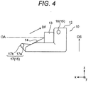
- FIG. 4 is a side view of the imaging unit 10 illustrated in FIG. 2 .
- the imaging unit 10 is a stereo camera including a pair of cameras 11. Note that the imaging unit 10 is not limited to a stereo camera, and may be a monocular camera.
- the imaging unit 10 includes the pair of cameras 11 and a housing 12 that holds the pair of cameras 11.
- the imaging unit 10 is positioned with high accuracy so that the mutually parallel optical axes OA of the pair of cameras 11 are set along the roll axis (x-axis) which is the longitudinal direction of the vehicle, and then fixed to the windshield WS via the bracket 20. That is, the direction of the optical axis OA of the imaging unit 10 is a direction intersecting the mounting direction DF of the imaging unit 10 and the support direction DS.
- each of the cameras 11 includes, for example, a lens, a lens barrel, an imaging element, an imaging substrate, or the like, and is fixedly supported by the housing 12.
- the housing 12 accommodates and holds the pair of cameras 11 accurately positioned so that the optical axes OA are mutually parallel, while accommodating a circuit board or the like including a signal processing circuit connected to an imaging circuit on the imaging substrate of each of the cameras 11.
- the housing 12 is formed of a metal such as stainless steel to have a shape extending in one direction having the maximum dimension in a direction perpendicularly intersecting the optical axis OA of the pair of cameras 11, that is, a direction parallel to a baseline length BL being a distance between the optical axes OA of the pair of cameras 11.
- the housing 12 defines the outer shape of the imaging unit 10, and a longitudinal direction DL of the housing 12 is the longitudinal direction DL of the imaging unit 10.
- the housing 12 holds the pair of cameras 11 in a camera holder 13 provided at both end portions in the longitudinal direction DL. With this configuration, it is possible to ensure the baseline length BL of the pair of cameras 11 of the imaging unit 10.
- the height of the forward side portion of the vehicle that is, the dimension of the portion on the positive side of the x-axis in the z-axis direction is smaller than the height of the rearward side portion of the vehicle, that is, the dimension of the portion on the negative side of the x-axis in the z-axis direction in accordance with the inclination of the windshield WS. That is, in the imaging unit 10, the height of the rear end portion in the mounting direction DF is lower than the height of the front end portion in the mounting direction DF.
- the housing 12 includes, between the pair of camera holder 13, an inclined surface 14 along the mounting direction DF of the imaging unit 10.
- the imaging unit 10 has a plurality of supported parts 15 provided at different positions of the housing 12 and supported by the bracket 20.
- the plurality of supported parts 15 of the imaging unit 10 includes three supported parts 15, namely, a pair of first supported parts 16 and one second supported part 17.
- the first supported part 16 is provided at a position being front end portions in the mounting direction DF of the imaging unit 10 and being both end portions in the longitudinal direction DL (y-axis direction) of the imaging unit 10.
- the second supported part 17 is provided at a position being the rear end portion in the mounting direction DF of the imaging unit 10 and being the center portion in the longitudinal direction DL of the imaging unit 10.
- the number of supported parts 15 is not limited to three, and may be four or more. Furthermore, the plurality of supported parts 15 is only required to include at least one first supported part 16, and can include at least one second supported part 17. For example, the plurality of supported parts 15 may include a plurality of the first supported parts 16 alone, or may include one first supported part 16 and one or more second supported parts 17, or may include two or more first supported parts 16 and two or more second supported parts 17.
- the supported part 15 has, at least partially, a pillar shape extending in the axial direction along a direction perpendicular to the mounting direction DF and the support direction DS.
- the axial direction of the pillar-shaped portion of each of the supported parts 15 is substantially parallel to the longitudinal direction DL of the imaging unit 10, that is, the pitch axis (y-axis) of the vehicle.
- the first supported part 16 provided at a position being the front end portion of the imaging unit 10 in the mounting direction DF and being both end portions of the imaging unit 10 in the longitudinal direction DL protrudes from the both side surfaces of the housing 12 toward outside of the housing 12 in the longitudinal direction DL of the imaging unit 10.
- the cross-sectional shape of the pillar-shaped first supported part 16 is preferably a circle, an ellipse, oval, or the like, so as to form a shape having a cylindrical curved surface.
- the first supported part 16 has a cylindrical shape, an elliptic cylindrical shape, or an oblong cylindrical shape, for example.
- the second supported part 17 provided at a position being the rear end portion of the imaging unit 10 in the mounting direction DF and being the center portion of the imaging unit 10 in the longitudinal direction DL includes a first portion 17a and a second portion 17b, for example.
- the first portion 17a protrudes rearward in the mounting direction DF of the imaging unit 10 from the center portion of the imaging unit 10 in the longitudinal direction DL.
- the second portion 17b is provided at the rear end of the first portion 17a in the mounting direction DF of the imaging unit 10.
- the second portion 17b has a pillar shape extending in the axial direction along a direction perpendicular to the mounting direction DF and the support direction DS of the imaging unit 10.
- the shape of the second portion 17b of the second supported part 17 is preferably a cylindrical shape, an elliptic cylindrical shape, or an oblong cylindrical shape, for example.
- the first portion 17a of the second supported part 17 is connected to the center portion in the axial direction of the pillar-shaped second portion 17b and extends in the direction perpendicular to the axial direction of the second portion 17b.
- This configuration allows the second supported part 17 to protrude toward both sides in the longitudinal direction DL of the imaging unit 10 from the first portion 17a protruding rearward in the mounting direction DF of the imaging unit 10. That is, as illustrated in FIG. 3 , the second supported part 17 is formed in a T-shape in a top view.
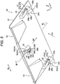
- FIG. 5 is a bottom perspective view of the bracket 20 of the imaging device 1 illustrated in FIG. 1 .
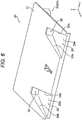
- FIG. 6 is a top perspective view of the bracket 20 illustrated in FIG. 5 .
- the bracket 20 is an integrally molded product shaped by integrally molding a resin material, for example.
- the bracket 20 includes, for example: a main body 21 on a flat plate; a pair of openings 22 opened in the main body 21 so as to expose the pair of cameras 11 of the imaging unit 10; a pair of light shielding portions 23 recessed in the upper surface of the main body 21; and a plurality of support structures 24 projecting from the lower surface of the main body 21 and configured to support the plurality of supported parts 15 of the imaging unit 10.
- the main body 21 is joined and fixed to the upper part on the inner side of the windshield WS of the vehicle, for example, via an adhesive.
- a slight gap is formed between the windshield WS and the forward side end portion of the main body 21 of the vehicle, that is, the rear end portion in the mounting direction DF of the imaging unit 10. This gap allows air to flow through this gap, making it possible to prevent dew condensation on the imaging device 1.
- the pair of openings 22 is provided to open at positions corresponding to the pair of cameras 11 of the imaging unit 10 mounted to the bracket 20, so as to be surrounded by the light shielding portion 23 as illustrated in FIG. 6 .
- the pair of openings 22 allows the pair of cameras 11 of the imaging unit 10 to be exposed toward the windshield WS, enabling photographing in front of the vehicle via the windshield WS by the imaging unit 10.
- the light shielding portion 23 is a recessed portion provided by recessing the upper surface of the main body 21 downward as viewed from the upper surface side of the main body 21 so as to be formed radially from the opening 22 toward the forward side of the vehicle in the optical axis OA direction of the imaging unit 10. As illustrated in FIG. 5 , a portion of the lower surface of the main body 21 corresponding to the light shielding portion 23 protrudes downward. As illustrated in FIG.
- the bottom surface 23a and the side surface 23b of the light shielding portion 23 surround the lower side and the lateral side of the opening 22 respectively to achieve a radial shape inclined to be away from the optical axis OA as moving from the camera 11 so as to prevent blocking the field of view of the camera 11 of the imaging unit 10.
- the light shielding portion 23 shields reflected light from the interior of the vehicle, for example, so as to reduce the influence of reflected light on the camera 11.
- the plurality of support structures 24 is provided to project from the lower surface of the main body 21 and supports the plurality of supported parts 15 of the imaging unit 10.
- the bracket 20 includes three support structures 24 corresponding to the three supported parts 15 of the imaging unit 10.
- the number of the support structures 24 of the bracket 20 is not limited to three and may be two, four or more, for example, corresponding to the number of the supported parts 15 of the imaging unit 10.
- the plurality of support structures 24 of the bracket 20 can include at least one first support structure 25 from the viewpoint of stably and reliably supporting the imaging unit 10 by using the bracket 20. That is, the plurality of support structures 24 of the bracket 20 may all be the first support structures 25, or may include three or more first support structures 25 corresponding to the supported parts 15 of the imaging unit 10.
- the plurality of support structures 24 of the bracket 20 may include at least one second support structure 26 from the viewpoint of facilitating the removal of the imaging unit 10 from the bracket 20. That is, the plurality of support structures 24 of the bracket 20 may all be the second support structures 26, or may include two or more second support structures 26 corresponding to the supported parts 15 of the imaging unit 10.
- the three support structures 24 of the bracket 20 include the pair of first support structures 25 that supports the pair of first supported parts 16 of the imaging unit 10, and the one second support structure 26 that supports the one second supported part 17 of the imaging unit 10.
- Each of the support structures 24 includes the receiving port 24a and a support 24b.
- the receiving port 24a opens rearward in the mounting direction DF of the imaging unit 10 and receives the supported part 15 of the imaging unit 10 toward the mounting direction DF.
- the support 24b supports the supported part 15 of the imaging unit 10 on the forward side of the receiving port 24a in the mounting direction DF of the imaging unit 10 from the support direction DS that intersects the mounting direction DF of the imaging unit 10.
- the first support structure 25 includes the receiving port 24a and the support 24b.
- the support 24b includes an engagement recess 27 and a guide part 28.
- the engagement recess 27 is provided in a recessed shape in the support direction DS of the imaging unit 10 and engages the supported part 15 of the imaging unit 10.
- the guide part 28 extends from the rear side to the forward side of the receiving port 24a in the mounting direction DF of the imaging unit 10.
- the support direction DS of the imaging unit 10 in the first support structure 25 is the up-down direction along the vertical direction.
- the engagement recess 27 supports the supported part 15 of the imaging unit 10 from below, and the guide part 28 supports the supported part 15 from above.
- the support 24b of the first support structure 25 includes, on the forward side of the guide part 28 in the mounting direction DF of the imaging unit 10, a claw-like engagement part 25a extending downward from above the guide part 28 in the support direction DS of the imaging unit 10.
- the engagement part 25a includes: the engagement recess 27 provided at a lower end portion of the imaging unit 10 in the support direction DS; and a guide surface 25b extending from below the receiving port 24a to the receiving port 24a in the support direction DS of the imaging unit 10.
- the engagement recess 27 provided in the support 24b of the first support structure 25 includes, at the rear end portion in the mounting direction DF of the imaging unit 10, an inclined surface 27a inclined rearward in the mounting direction DF with respect to the support direction DS (z-axis direction) of the imaging unit 10.
- the engagement recess 27 further includes, at the front end portion in the mounting direction DF of the imaging unit 10, an inclined surface 27b inclined forward in the mounting direction DF of the imaging unit 10 with respect to the support direction DS of the imaging unit 10.
- the guide part 28 provided on the support 24b of the first support structure 25 extends from the rear side to the forward side of the receiving port 24a in the mounting direction DF of the imaging unit 10.
- the guide part 28 has a rear end portion in the mounting direction DF of the imaging unit 10 defined as a fixed end, a front end portion in the mounting direction DF defined as a free end, and uses its front end portion to bias the supported part 15 toward the engagement recess 27.
- the interval between the free end of the guide part 28 and the engagement recess 27 is shorter in a state where the imaging unit 10 is not supported by the bracket 20 illustrated in FIG. 5 as compared with the state where the imaging unit 10 is supported by the bracket 20 illustrated in FIG. 1 .
- the guide part 28 is provided in the form of a leaf spring which is elastically deformed by receiving a force in the up-down direction being the support direction DS of the imaging unit 10.
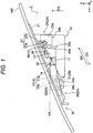
- FIG. 7 is an enlarged sectional view taken along line VII-VII of the second support structure 26 of the bracket 20 illustrated in FIG. 5 . Note that FIG. 7 illustrates the state in which the second supported part 17 of the imaging unit 10 is held by the second support structure 26.
- the support 24b of the second support structure 26 of the bracket 20 includes a pair of guide parts 29.
- the pair of guide parts 29 is opposed in the support direction DS of the imaging unit 10, that is, in the up-down direction, and extends from the rearward side to the forward side of the receiving port 24a in the mounting direction DF of the imaging unit 10.
- the pair of guide parts 29 of the second support structure 26 includes: a first guide part 31 that supports the second supported part 17 of the imaging unit 10 from below; and a second guide part 32 that supports the second supported part 17 of the imaging unit 10 from above.
- the second guide part 32 out of the pair of guide parts 29 of the second support structure 26 has a configuration similar to the configuration of the guide part 28 of the first support structure 25 illustrated in FIG. 1 described above.
- the second guide part 32 has a rear end portion in the mounting direction DF of the imaging unit 10 defined as a fixed end, a front end portion in the mounting direction DF of the imaging unit 10 defined as a free end, and uses its front end portion to bias the supported part 15 toward the first guide part 31.
- the imaging device 1 of the present embodiment is configured such that the second support structure 26 of the bracket 20 includes a pair of guide walls 30 being opposed in the longitudinal direction DL (y-axis direction) of the imaging unit 10 and extending in the up-down direction being the support direction DS of the imaging unit 10 as illustrated in FIG. 5 .
- the first guide part 31 out of the pair of guide parts 29 of the second support structure 26 is provided on each of the pair of guide walls 30.
- the second guide part 32 out of the pair of guide parts 29 of the second support structure 26 is disposed between the pair of guide walls 30.
- the pair of guide walls 30 of the second support structure 26 includes: a first guide surface 30a; a second guide surface 30b; and an inlet 30c, individually on each of opposing surfaces in the longitudinal direction DL of the imaging unit 10.
- the first guide surface 30a extends in the up-down direction from below the receiving port 24a that receives the second supported part 17 of the imaging unit 10 to the receiving port 24a.
- the second guide surface 30b extends in the up-down direction with respect to the first guide surface 30a so as to be opposed in the rear side in the mounting direction DF of the imaging unit 10.
- the inlet 30c opens downward between the first guide surface 30a and the second guide surface 30b, and upwardly receives the second supported part 17 of the imaging unit 10.
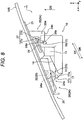
- FIG. 8 is a side view illustrating a procedure of mounting the imaging unit 10 to the bracket 20 in the imaging device 1 of the present embodiment illustrated in FIG. 1 .
- the imaging device 1 of the present embodiment includes the imaging unit 10 and the bracket 20 that can be used to mount the imaging unit 10 in the mounting direction DF.
- the imaging unit 10 includes the plurality of supported parts 15 supported by the bracket 20, and the bracket 20 includes the plurality of support structures 24 that supports the plurality of supported parts 15 of the imaging unit 10.
- the support structure 24 includes: the receiving port 24a opened toward the rear of a mounting direction DF of the imaging unit 10 for receiving the supported parts 15 of the imaging unit 10 in the mounting direction DF; and the support 24b that supports the supported parts 15 on the forward side of this receiving port 24a in the mounting direction DF of the imaging unit 10 from the support direction DS that intersects the mounting direction DF of the imaging unit 10.
- the imaging unit 10 can be mounted to the bracket 20 fixed to the upper part of the front windshield WS of the vehicle by using the following procedure, for example. First, the plurality of supported parts 15 of the imaging unit 10 is aligned with the plurality of support structures 24 of the bracket 20. Thereafter, sliding the imaging unit 10 in the mounting direction DF causes the plurality of supported parts 15 of the imaging unit 10 to be received by the receiving port 24a provided in each of the plurality of support structures 24 of the bracket 20 and that opens toward the rear in the mounting direction DF.
- sliding the imaging unit 10 rearward in the mounting direction DF that is, in a removing direction DR opposite to the mounting direction DF causes the plurality of supported parts 15 of the imaging unit 10 to move from the support 24b of the plurality of support structures 24 of the bracket 20 to the receiving port 24a.
- Sliding the imaging unit 10 further in the removing direction DR causes the plurality of supported parts 15 of the imaging unit 10 to move in the removing direction DR from the receiving ports 24a of the plurality of support structures 24 of the bracket 20, leading to release of a support of the plurality of supported parts 15 of the imaging unit 10 provided by the plurality of support structures 24 of the bracket 20.
- the imaging device 1 of the present embodiment it is only necessary to slide the imaging unit 10 in a predetermined mounting direction DF or its opposite direction, namely, the removing direction DR at the time of mounting and removing the imaging unit 10 to and from the bracket 20, making it possible to easily perform the mounting/removal of the imaging unit 10 with simpler operation than the conventional technique.
- the imaging unit 10 there is no need to turn the imaging unit 10, making it possible to reduce the work space as compared with the conventional technique.
- the plurality of support structures 24 of the bracket 20 of the imaging device 1 of the present embodiment may include at least one first support structure 25.
- the bracket 20 includes two first support structures 25.
- the first support structure 25 includes the guide part 28 extending from the rear side to the forward side of the receiving port 24a in the mounting direction DF of the imaging unit 10.
- the plurality of support structures 24 of the bracket 20 of the imaging device 1 of the present embodiment may include at least one second support structure 26.
- the bracket 20 includes one second support structure 26.
- the support 24b of the second support structure 26 includes the pair of guide parts 29 opposed in the support direction DS of the imaging unit 10 and extending from the rear side to the forward side of the receiving port 24a in the mounting direction DF of the imaging unit 10.
- the second supported part 17 of the imaging unit 10 when the plurality of supported parts 15 of the imaging unit 10 is received in the receiving ports 24a of the plurality of support structures 24 of the bracket 20, it is possible to arrange the second supported part 17 of the imaging unit 10 between the pair of guide parts 29 on the rearward side in the mounting direction DF of the imaging unit 10 with respect to the receiving port 24a of the second support structure 26. Thereafter, it is possible to use the pair of guide parts 29 to guide the second supported part 17 of the imaging unit 10 and slide it in the mounting direction DF of the imaging unit 10. This makes it possible to facilitate reception of the second supported part 17 of the imaging unit 10 by the receiving port 24a of the second support structure 26.
- the support 24b of the first support structure 25 of the bracket 20 includes the engagement recess 27 for engaging the first supported part 16 of the imaging unit 10.
- the engagement recess 27 is provided in a downward recessed shape in the up-down direction being the support direction DS of the imaging unit 10 intersecting the mounting direction DF of the imaging unit 10.
- the first supported part 16 of the imaging unit 10 engages the engagement recess 27 provided on the support 24b of the first support structure 25 of the bracket 20 downward in the support direction DS that intersects the mounting direction DF of the imaging unit 10, leading to restriction of the front-rear movement of the imaging unit 10 in the mounting direction DF. Moreover, the first supported part 16 of the imaging unit 10 is supported from both sides in the support direction DS between the engagement recess 27 and the guide part 28, which are opposed to each other in the support direction DS in the first support structure 25. With this configuration, even when vibration or shock acts on the imaging unit 10, the first support structure 25 of the bracket 20 can further stably and reliably support the first supported part 16 of the imaging unit 10
- the support 24b of the second support structure 26 of the bracket 20 includes the pair of guide parts 29 opposed in the support direction DS of the imaging device 1 and extending from the rearward side to the forward side of the receiving port 24a in the mounting direction DF of the imaging unit 10, as described above. Therefore, the second supported part 17 of the imaging unit 10 received in the mounting direction DF of the imaging unit 10 from the receiving port 24a of the second support structure 26 can be supported by the pair of guide parts 29 from both sides in the support direction DS of the imaging unit 10. With this configuration, even when vibration or shock acts on the imaging unit 10, the second support structure 26 of the bracket 20 can further stably and reliably support the second supported part 17 of the imaging unit 10
- the imaging unit 10 has its maximum dimension in the longitudinal direction DL intersecting the mounting direction DF and the support direction DS. Furthermore, in the imaging unit 10, the plurality of supported parts 15 includes: the pair of first supported parts 16 provided at a position being at the front end portion in the mounting direction DF and being at both end portions in the longitudinal direction DL; and at least one second supported parts 17 provided at a position being at the rear end portion in the mounting direction DF and being at the center portion in the longitudinal direction DL. In the illustrated example, the imaging unit 10 has one second supported part 17.
- the plurality of support structures 24 of the bracket 20 can include: the pair of first support structures 25 that supports the pair of first supported parts 16 of the imaging unit 10; and at least one second support structure 26 that supports at least one second supported part 17 of the imaging unit 10.
- the plurality of support structures 24 of the bracket 20 includes one second support structure 26.
- the imaging unit 10 it is possible to support the imaging unit 10 at three points in total, that is, at one point being at the rear end portion of the mounting direction DF of the imaging unit 10 and being at the center portion in the longitudinal direction DL and two points being at the front end portion in the mounting direction DF of the imaging unit 10 and being at both end portions of the longitudinal direction DL of the imaging unit 10.
- the imaging unit 10 it is also possible to support the imaging unit 10 at four points or more in total, that is, at two points or more being at the rear end portion in the mounting direction DF of the imaging unit 10 and being at the center portion in the longitudinal direction DL, and two points being at the front end in the mounting direction DF of the imaging unit 10 and being at both end portions in the longitudinal direction DL of the imaging unit 10. Therefore, in a case where the imaging unit 10 is a stereo camera having the direction of the baseline length BL defined as the longitudinal direction DL, it is possible to achieve accurate positioning and stable support of the imaging unit 10, leading to improvement of measurement accuracy of the distance or the like to the photographing target.
- the support direction DS of the imaging unit 10 by the bracket 20 is the up-down direction along the vertical direction.
- the engagement recess 27 supports the first supported part 16 of the imaging unit 10 from below
- the guide part 28 supports the first supported part 16 of the imaging unit 10 from above.
- the pair of guide parts 29 of the second support structure 26 of the bracket 20 includes the first guide part 31 and the second guide part 32.
- the first guide part 31 supports the supported part 15 of the imaging unit 10 from below
- the second guide part 32 supports the supported part 15 of the imaging unit 10 from above.
- the second support structure 26 of the bracket 20 can further stably and reliably support the second supported part 17 of the imaging unit 10 from both sides in the up-down direction as well.
- the engagement recess 27 provided in the support 24b of the first support structure 25 of the bracket 20 includes, at the rear end portion in the mounting direction DF of the imaging unit 10, the inclined surface 27a inclined rearward in the mounting direction DF of the imaging unit 10 with respect to the support direction DS of the imaging unit 10.
- the engagement recess 27 provided in the support 24b of the first support structure 25 of the bracket 20 includes, at the front end portion in the mounting direction DF of the imaging unit 10, the inclined surface 27b inclined forward in the mounting direction DF of the imaging unit 10 with respect to the support direction DS of the imaging unit 10.
- the first supported part 16 of the imaging unit 10 that has been guided by the inclined surface 27a on the rear end side of the engagement recess 27 in the mounting direction DF of the imaging unit 10 from the receiving port 24a of the first support structure 25 to the bottom of the engagement recess 27 to be supported by being abutting against the inclined surface 27b on the forward side in the mounting direction DF of the imaging unit 10 That is, the first supported part 16 of the imaging unit 10 can be held between the pair of V-shaped inclined surfaces 27a and 27b opposing in the mounting direction DF of the imaging unit 10 in the engagement recess 27. Accordingly, the first support structure 25 of the bracket 20 can stably and reliably support the first supported part 16 of the imaging unit 10.
- the guide part 28 provided on the support 24b of the first support structure 25 of the bracket 20 has the rear end portion in the mounting direction DF of the imaging unit 10 defined as a fixed end, while having the front end portion in the mounting direction DF of the imaging unit 10 defined as a free end.
- the front end portion defined as the free end of the guide part 28 biases the first supported part 16 of the imaging unit 10 toward the engagement recess 27 of the first support structure 25. This makes it possible to reliably engage the first supported part 16 of the imaging unit 10 with the engagement recess 27 of the first support structure 25 and possible to stably and reliably support the first supported part 16 of the imaging unit 10 by using the first support structure 25 of the bracket 20.
- the second guide part 32 provided on the support 24b of the second support structure 26 of the bracket 20 has the rear end portion in the mounting direction DF of the imaging unit 10 defined as a fixed end while having the front end portion in the mounting direction DF of the imaging unit 10 defined as a free end similarly to the guide part 28 of the first support structure 25.
- the front end portion defined as the free end of the second guide part 32 biases the second supported part 17 of the imaging unit 10 toward the first guide part 31. This makes it possible to sandwich the second supported part 17 of the imaging unit 10 between the pair of guide parts 29 of the second support structure 26, and possible to stably and reliably support the second supported part 17 of the imaging unit 10 by using the second support structure 26 of the bracket 20.
- the removal of the imaging unit 10 from the bracket 20 it is possible, as described above, to slide the imaging unit 10 in the removing direction DR opposite to the mounting direction DF and to slide the second supported part 17 of the imaging unit 10 in the removing direction DR between the first guide part 31 and the second guide part 32 of the second support structure 26 of the bracket 20.
- the second supported part 17 of the imaging unit 10 can easily reach the receiving port 24a of the second support structure 26, and the second supported part 17 of the imaging unit 10 2 can be easily removed from the second support structure 26.
- the support 24b of the first support structure 25 of the bracket 20 includes, on the forward side of the guide part 28 in the mounting direction DF of the imaging unit 10, the engagement part 25a extending downward from above the guide part 28 in the support direction DS of the imaging unit 10.
- the engagement part 25a includes: the engagement recess 27 provided at a lower end portion of the imaging unit 10 in the support direction DS; and a guide surface 25b extending from below the receiving port 24a to the receiving port 24a in the support direction DS of the imaging unit 10.
- the first supported part 16 of the imaging unit 10 can be abutted against the guide surface 25b of the support 24b of the first support structure 25 of the bracket 20 to be pressed forward in the mounting direction DF, enabling sliding the front end portion in the mounting direction DF of the imaging unit 10 upward in the support direction DS.
- This makes it possible to allow the first supported part 16 of the imaging unit 10 to be guided to the receiving port 24a by using the guide surface 25b of the first support structure 25 to be easily received by the receiving port 24a and engaged with the engagement recess 27. Therefore, at the time of mounting the imaging unit 10 to the bracket 20, it is possible to easily support the first supported part 16 of the imaging unit 10 by using the first support structure 25 of the bracket 20.
- the imaging unit 10 has its maximum dimension in the longitudinal direction DL intersecting the mounting direction DF and the support direction DS as described above.
- the second support structure 26 of the bracket 20 includes the pair of guide walls 30 extending in the up-down direction being opposed in the longitudinal direction DL of the imaging unit 10.
- the first guide part 31 of the second support structure 26 is provided on each of the pair of guide walls 30, while the second guide part 32 is disposed between the pair of guide walls 30.
- Each of the guide walls 30 includes the first guide surface 30a, the second guide surface 30b, and the inlet 30c.
- the first guide surface 30a extends from below the receiving port 24a of the second support structure 26 to the receiving port 24a in the up-down direction.
- the second guide surface 30b extends in the up-down direction with respect to the first guide surface 30a so as to be opposed in the rear side in the mounting direction DF of the imaging unit 10.
- the inlet 30c opens downward between the first guide surface 30a and the second guide surface 30b so as to downwardly expose a part of the second guide part 32 of the second support structure 26, and also upwardly receives the supported part 15 of the imaging unit 10.
- the second supported part 17 of the imaging unit 10 can be received from downward to the inlet 30c between the first guide surface 30a and the second guide surface 30b provided on the pair of guide walls 30 of the second support structure 26 of the bracket 20. Further upwardly moving the rear end portion of the imaging unit 10 in the mounting direction DF allows the second supported part 17 of the imaging unit 10 to be guided upward between the first guide surface 30a and the second guide surface 30b to be abutted against the second guide part 32 arranged between the pair of guide walls 30 of the second support structure 26 of the bracket 20 from below.
- the supported part 15 of the imaging unit 10 has a pillar shape extending in the axial direction along a direction perpendicular to the mounting direction DF and the support direction DS. This makes it is possible to stably and reliably support the supported part 15 of the imaging unit 10 from the support direction DS intersecting in the axial direction by the support structure 24 of the bracket 20.
- the supported part 15 of the imaging unit 10 can be abutted against the guide surface 25b of the first support structure 25 extending in the support direction DS intersecting in the axial direction or abutted against the first guide surface 30a and the second guide surface 30b of the second support structure 26 to be guided in the support direction DS. Furthermore, the supported part 15 of the imaging unit 10 can be abutted against the guide part 28 of the first support structure 25 and the pair of guide parts 29 of the second support structure 26 extending in the mounting direction DF intersecting in the axial direction, so as to be guided in the mounting direction DF. Accordingly, it is possible to facilitate the mounting and removal of the imaging unit 10 to and from the bracket 20.
- the second supported part 17 of the imaging unit 10 includes the first portion 17a protruding rearward in the mounting direction DF from the center portion in the longitudinal direction DL of the imaging unit 10.
- the second supported part 17 of the imaging unit 10 is provided at the rear end of the mounting direction DF of the first portion 17a and includes the pillar-shaped second portion 17b extending in the axial direction along a direction perpendicular to the mounting direction DF and the support direction DS.
- both ends in the axial direction of the second portion 17b of the second supported part 17 provided in the center portion in the longitudinal direction DL at the rear end portion of the mounting direction DF of the imaging unit 10 can be guided by the first guide surface 30a and the second guide surface 30b of the pair of guide walls 30 of the second support structure 26 being opposed in the longitudinal direction DL. Therefore, the second supported part 17 of the imaging unit 10 can be easily mounted to the second support structure 26 of the bracket 20 or easily removed from the second support structure 26.
- the mounting direction DF of the imaging unit 10 is a direction along the inclination of the windshield WS of the vehicle that intersects with the support direction DS and the optical axis OA direction of the imaging unit 10. Therefore, in mounting the imaging unit 10 to the bracket 20 or removing it from the bracket 20, it is possible to prevent the imaging unit 10 from interfering with the windshield WS, leading to facilitation of mounting of the imaging unit 10.
- the imaging unit 10 is moved in a direction away from the windshield WS at the time of allow the imaging unit 10 to slide in the removing direction DR opposite to the mounting direction DF. Therefore, at the removal of the imaging unit 10 from the bracket 20, interference between the imaging unit 10 and the windshield WS can be further reliably prevented, and the imaging unit 10 can be further easily removed.
- the imaging device 1 of the present embodiment it is only necessary to slide the imaging unit 10 in a predetermined mounting direction DF or its opposite direction, namely, the removing direction DR at the time of mounting and removing the imaging unit 10 to and from the bracket 20, making it possible to easily perform the mounting/removal of the imaging unit 10 with simpler operation than the conventional technique.
- the imaging unit 10 there is no need to turn the imaging unit 10, making it possible to reduce the work space as compared with the conventional technique.
- FIGS. 9 to 12 a second embodiment of an imaging device of the present invention will be described with reference to FIGS. 9 to 12 .
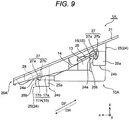
- FIG. 9 is a side view of an imaging device 1A according to the second embodiment of the present invention.
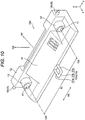
- FIG. 10 is a top perspective view of an imaging unit 10A of the imaging device 1A illustrated in FIG. 9 .
- FIG. 11 is a bottom perspective view of a bracket 20A of the imaging device 1A illustrated in FIG. 9 .
- the imaging device 1A of the present embodiment differs from the imaging device 1 of the first embodiment in that a second supported part 17A of the imaging unit 10A has a different configuration and that it includes the first support structure 25 instead of the second support structure 26 at the rear end portion of the bracket 20A in the mounting direction DF of the imaging unit 10A. Since the other configurations of the imaging device 1A of the present embodiment are similar to those of the imaging device 1 of the above-described first embodiment, the similar portions are denoted by the same reference numerals, and description is omitted.
- the imaging unit 10A of the imaging device 1A of the present embodiment includes the second supported part 17A at a position being the rear end portion in the mounting direction DF and being the center portion in the longitudinal direction DL.
- the second supported part 17A includes: a pair of first portions 17a projecting rearward in the mounting direction DF from the center portion in the longitudinal direction DL of the imaging unit 10A; and a pillar-shaped second portion 17b provided at the rear end in the mounting direction DF of the pair of first portions 17a and extending in an axial direction along a direction perpendicular to the mounting direction DF and the support direction DS.
- the pair of first portions 17a extends substantially in parallel to the direction of the optical axis OA of the imaging unit 10A and the roll axis (x-axis) of the vehicle, while the second portion 17b extends in the axial direction that is substantially perpendicular to the direction of the optical axis OA of the imaging unit 10A and substantially parallel to the pitch axis (y-axis) of the vehicle.
- the second supported part 17A has both end portions of the second portion 17b in the axial direction being connected to the rear end portions of the pair of first portions 17a in the mounting direction DF of the imaging unit 10A, and thus is shaped in approximately a U-shape in top view so as to be formed into an annular shape having an opening between the second supported part 17A and the housing 12 of the imaging unit 10A.
- the plurality of support structures 24 of the bracket 20A of the imaging device 1A of the present embodiment includes three first support structures 25.
- the bracket 20A includes the pair of first support structures 25 at a position being a front end portion in the mounting direction DF of the imaging unit 10A and being both end portions in the longitudinal direction DL of the imaging unit 10A, and includes one first support structure 25 at a position being the rear end portion in the mounting direction DF of the imaging unit 10A and being the center portion in the longitudinal direction DL of the imaging unit 10A.
- FIG. 12 is an enlarged view of the first support structure 25 provided at the rear end portion in the mounting direction DF of the imaging unit 10A of the bracket 20A illustrated in FIG. 11 .
- FIG. 12 illustrates a state in which the second supported part 17A of the imaging unit 10A is supported by the first support structure 25, as illustrated in FIG. 9 .
- the second supported part 17A of the imaging unit 10A is supported by the first support structure 25 provided at the rear end portion of the bracket 20A in the mounting direction DF of the imaging unit 10A, in a similar manner to the first supported part 16 of the imaging unit 10A.
- the imaging device 1A of the present embodiment it is possible not merely to obtain the similar effect to that of the imaging device 1 of the first embodiment but also to support the second supported part 17A of the imaging unit 10A further stably and reliably by using the first support structure 25 provided at the rear end portion of the bracket 20A in the mounting direction DF of the imaging unit 10A.
- FIGS. 13 to 15 third embodiment of an imaging device of the present invention will be described with reference to FIGS. 13 to 15 .
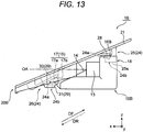
- FIG. 13 is a side view of an imaging device 1B according to the third embodiment of the present invention.
- FIG. 14 is a top perspective view from of an imaging unit 10B of the imaging device 1B illustrated in FIG. 13 .
- FIG. 15 is a bottom perspective view of a bracket 20B of the imaging device 1B illustrated in FIG. 13 .
- the imaging device 1B of the present embodiment is different from the imaging device 1 of the first embodiment in the configuration of a first supported part 16B of the imaging unit 10B. Since the other configurations of the imaging device 1B of the present embodiment are similar to those of the imaging device 1 of the above-described first embodiment, the same parts are denoted by the same reference numerals and description is omitted.
- the imaging unit 10B of the imaging device 1B of the present embodiment includes a pair of recesses 18 for accommodating the lower end portion of the pair of first support structure 25 of the bracket 20B at a position being the front end portion of the housing 12 in the mounting direction DF and being both end portions in the longitudinal direction DL.
- the imaging unit 10B includes a pair of the first supported parts 16B extending over the pair of recesses 18 on an end surface on the upper side of the housing 12 in the support direction DS.
- the first supported part 16B of the imaging unit 10B is has a pillar shape having the longitudinal direction DL of the imaging unit 10B as its axial direction, with both end portions in the axial direction fixed to the housing 12. As illustrated in FIG. 13 , the first supported part 16B has a semicircular pillar shape having a flat surface supported by the guide part 28 of the first support structure 25 of the bracket 20B.
- the pair of first support structures 25 of the bracket 20B is more miniaturized than the pair of first support structures 25 provided in the bracket 20 of the imaging device 1 of the first embodiment illustrated in FIG. 5 , facilitating accommodation of its lower end portion into the recess 18 of the housing 12 of the imaging unit 10B.
- the imaging device 1B of the present embodiment it is not merely possible to achieve the similar effect to that of the imaging device 1 of the first embodiment described above, but also possible to suppress projection of the pair of first supported parts 16B of the imaging unit 10B in the longitudinal direction DL of the imaging unit 10B, enabling arranging the pair of first support structures 25 of the bracket 20B on an inner side of the both ends of the imaging unit 10B in the longitudinal direction DL. This makes it possible to achieve miniaturization and weight reduction of the imaging device 1B.
Landscapes
- Engineering & Computer Science (AREA)
- Physics & Mathematics (AREA)
- General Physics & Mathematics (AREA)
- Multimedia (AREA)
- Signal Processing (AREA)
- Mechanical Engineering (AREA)
- Fittings On The Vehicle Exterior For Carrying Loads, And Devices For Holding Or Mounting Articles (AREA)
- Studio Devices (AREA)
- Camera Bodies And Camera Details Or Accessories (AREA)
- Accessories Of Cameras (AREA)
Abstract
Description
- The present invention relates to an imaging device.
- Conventionally, there is known an invention related to a camera unit including a camera main body and a bracket that removably supports the camera main body to fix the camera main body to a mounting target such as a windshield of a vehicle (refer to, for example,
PTL 1 below). - In the conventional camera unit described in
PTL 1, the camera main body has a hook-shaped portion to be hooked on the bracket, and the bracket includes a first support that hooks the hook-shaped portion to turnably support the camera main body, and a second support that fixedly supports the main body (refer to the same PTL,Claim 1, or the like). -
PTL 1 discloses capability of fixing the camera main body by the camera unit without sliding the camera main body and capability of improving the degree of freedom in design or achieving space saving in the camera unit (refer to the same PTL, Paragraph 0008 or the like). - PTL 1:
JP 2015-20695 A - At the time of mounting the camera main body to the bracket in the conventional camera unit, there is a need to hook the hook-shaped portion of the camera main body to the first support of the bracket, turn the camera main body for positioning, and fix the camera main body to the bracket via the second support of the bracket.
- In addition, at the removal of the camera main body from the bracket, there is a need to perform reversed operation of the operation of mounting the camera main body to the bracket. This would complicate the operation in mounting/removing the camera main body to/from the bracket. This not only results in problems of complicating the mounting /removal of the camera main body but also generates necessity to provide a large work space for turning the camera main body.
- The present invention has been made in view of the above problem, and an object thereof is to provide an imaging device capable of easily mounting/removing an imaging unit by simpler operation than in the conventional technique when mounting/removing the imaging unit to and from a bracket, and to reduce more work space than in the conventional technique.
- In order to achieve the above object, an imaging device of the present invention is an imaging device including an imaging unit and a bracket capable of mounting the imaging unit in a mounting direction, in which the imaging unit includes a plurality of supported parts supported by the bracket, the bracket includes a plurality of support structures for supporting the plurality of supported parts, and the support structure includes: a receiving port that opens toward the rear in the mounting direction to receive the supported part in the mounting direction; and a support for supporting the supported part on the forward side in the mounting direction of the receiving port from a support direction that intersects the mounting direction.
- At the time of mounting the imaging unit to the bracket in the imaging device of the present invention, sliding the imaging unit in a predetermined mounting direction causes the plurality of supported parts of the imaging unit to be received by the receiving port provided in each of the plurality of support structures of the bracket and that opens toward the rear in the mounting direction. Further sliding the imaging unit in the mounting direction causes the plurality of supported parts of the imaging unit to move to the forward side in the mounting direction of the receiving ports of the plurality of support structures, so as to allow the imaging unit to be supported by the support provided in each of the plurality of support structures from a support direction that intersects the mounting direction. With the above-described procedure, the imaging unit is mounted to the bracket.
- Furthermore, at the removal of the imaging unit from the bracket in the imaging device of the present invention, sliding the imaging unit rearward in the mounting direction, that is, in a removing direction opposite to the mounting direction causes the plurality of supported parts of the imaging unit to move from the support of the plurality of support structures to the receiving port. Further sliding the imaging unit in a removing direction causes the plurality of supported parts of the imaging unit to move in the removing direction from the receiving ports of the plurality of support structures of the bracket, so as to release support of the plurality of supported parts of the imaging unit provided by the plurality of support structures of the bracket. With the above-described procedure, the imaging unit is removed from the bracket.
- Therefore, according to the imaging device of the present invention, it is only necessary to slide the imaging unit in a predetermined mounting direction or its opposite direction at the time of mounting and removing the imaging unit to and from the bracket, making it possible to easily perform the mounting/removal of the imaging unit with simpler operation than the conventional technique. In addition, there is no need to turn the imaging unit, making it possible to reduce the work space as compared with the conventional technique.
-
-
FIG. 1 is a side view of an imaging device according to a first embodiment of the present invention. -
FIG. 2 is a top perspective view of an imaging unit of the imaging device illustrated inFIG. 1 . -
FIG. 3 is a top view of the imaging unit illustrated inFIG. 2 . -
FIG. 4 is a side view of the imaging unit illustrated inFIG. 2 . -
FIG. 5 is a bottom perspective view of a bracket of the imaging device illustrated inFIG. 1 . -
FIG. 6 is a top perspective view of the bracket of the imaging device illustrated inFIG. 1 . -
FIG. 7 is an enlarged sectional view taken along line VII-VII of a second support structure of the bracket illustrated inFIG. 5 . -
FIG. 8 is a side view illustrating a procedure for mounting the imaging unit to the bracket of the imaging device illustrated inFIG. 1 . -
FIG. 9 is a side view of an imaging device according to a second embodiment of the present invention. -
FIG. 10 is a top perspective view of the imaging unit of the imaging device illustrated inFIG. 9 . -
FIG. 11 is a bottom perspective view of the bracket of the imaging device illustrated inFIG. 9 . -
FIG. 12 is an enlarged view of a first support structure of the bracket illustrated inFIG. 11 . -
FIG. 13 is a side view of an imaging device according to a third embodiment of the present invention. -
FIG. 14 is a top perspective view of the imaging unit of the imaging device illustrated inFIG. 13 . -
FIG. 15 is a bottom perspective view of the bracket of the imaging device illustrated inFIG. 13 . - Embodiments of an imaging device according to the present invention will be described below with reference to the drawings.
-
FIG. 1 is a side view of animaging device 1 according to a first embodiment of the present invention. Theimaging device 1 of the present embodiment is an in-vehicle imaging device 1 mounted on a vehicle such as an automobile. For example, theimaging device 1 is mounted on an upper portion of a windshield WS of the vehicle, and is used to capture an image of the forward direction of the vehicle through the windshield WS to obtain the distance and velocity of the captured object. Each of the drawings includingFIG. 1 illustrates an orthogonal coordinate system having vehicle axes, that is, a roll axis being an x-axis, a pitch axis being a y-axis, and a yaw axis being a z-axis. - The
imaging device 1 includes animaging unit 10 and abracket 20 that can be used to slidably mounting theimaging unit 10 in a predetermined mounting direction DF. In thebracket 20, for example, a flat plate-likemain body 21 is disposed at a predetermined position on the upper portion of the windshield WS along the inner surface of the windshield WS to be inclined with respect to the roll axis (x-axis) and the yaw axis (z-axis) of the vehicle and is fixed to the inner surface of the windshield WS with an adhesive or the like. - The mounting direction DF of the
imaging unit 10 with respect to thebracket 20 is a direction generally along the inclination of themain body 21 of thebracket 20 and the windshield WS while being a direction inclined with respect to the roll axis (x-axis) and the yaw axis (z-axis) of the vehicle. Note that in the mounting direction DF of theimaging unit 10, the direction being the negative side in the x-axis direction and being the positive side in the z-axis direction, that is, the direction being the rear side of the vehicle and being the upward side in the vertical direction is defined as a forward direction, while the direction being the positive side in the x-axis direction and being the negative side in the z-axis direction, that is, the direction being the forward side of the vehicle and being the downward side in the vertical direction is defined as a rearward direction. - A support direction DS of the
imaging unit 10 by thebracket 20 is a direction that intersects the mounting direction DF of theimaging unit 10 and is a direction substantially parallel to the yaw axis (z-axis) of the vehicle. The support direction DS of theimaging unit 10 is also a direction along the vertical direction in a vehicle traveling on a flat road surface having no inclination, for example. For example, in the mounting direction DF of theimaging unit 10, the inclination angle with respect to the roll axis (x-axis) of the vehicle is smaller than the inclination angle with respect to the yaw axis (z-axis) of the vehicle. - From the viewpoint of facilitating mounting and removal of the
imaging unit 10 with respect to thebracket 20, the inclination angle in the mounting direction DF with respect to an optical axis OA of theimaging unit 10, which is substantially parallel to the roll axis (x-axis), is preferably greater than the inclination angle of themain body 21 of thebracket 20 with respect to the optical axis OA. In the case of mounting thebracket 20 to a ceiling portion of the vehicle, the mounting direction DF of theimaging unit 10 with respect to thebracket 20 may be set to a direction along the ceiling portion of the vehicle, for example. -
FIG. 2 is a top perspective view of theimaging unit 10 illustrated inFIG. 1 .FIG. 3 is a top view of theimaging unit 10 illustrated inFIG. 2 .FIG. 4 is a side view of theimaging unit 10 illustrated inFIG. 2 . In the illustrated example, theimaging unit 10 is a stereo camera including a pair ofcameras 11. Note that theimaging unit 10 is not limited to a stereo camera, and may be a monocular camera. - The
imaging unit 10 includes the pair ofcameras 11 and ahousing 12 that holds the pair ofcameras 11. For example, theimaging unit 10 is positioned with high accuracy so that the mutually parallel optical axes OA of the pair ofcameras 11 are set along the roll axis (x-axis) which is the longitudinal direction of the vehicle, and then fixed to the windshield WS via thebracket 20. That is, the direction of the optical axis OA of theimaging unit 10 is a direction intersecting the mounting direction DF of theimaging unit 10 and the support direction DS. Although not illustrated, each of thecameras 11 includes, for example, a lens, a lens barrel, an imaging element, an imaging substrate, or the like, and is fixedly supported by thehousing 12. - The
housing 12 accommodates and holds the pair ofcameras 11 accurately positioned so that the optical axes OA are mutually parallel, while accommodating a circuit board or the like including a signal processing circuit connected to an imaging circuit on the imaging substrate of each of thecameras 11. - For example, the
housing 12 is formed of a metal such as stainless steel to have a shape extending in one direction having the maximum dimension in a direction perpendicularly intersecting the optical axis OA of the pair ofcameras 11, that is, a direction parallel to a baseline length BL being a distance between the optical axes OA of the pair ofcameras 11. Thehousing 12 defines the outer shape of theimaging unit 10, and a longitudinal direction DL of thehousing 12 is the longitudinal direction DL of theimaging unit 10. Thehousing 12 holds the pair ofcameras 11 in acamera holder 13 provided at both end portions in the longitudinal direction DL. With this configuration, it is possible to ensure the baseline length BL of the pair ofcameras 11 of theimaging unit 10. - As illustrated in
FIG. 1 , in thehousing 12, the height of the forward side portion of the vehicle, that is, the dimension of the portion on the positive side of the x-axis in the z-axis direction is smaller than the height of the rearward side portion of the vehicle, that is, the dimension of the portion on the negative side of the x-axis in the z-axis direction in accordance with the inclination of the windshield WS. That is, in theimaging unit 10, the height of the rear end portion in the mounting direction DF is lower than the height of the front end portion in the mounting direction DF. In addition, thehousing 12 includes, between the pair ofcamera holder 13, aninclined surface 14 along the mounting direction DF of theimaging unit 10. - The
imaging unit 10 has a plurality of supportedparts 15 provided at different positions of thehousing 12 and supported by thebracket 20. In the illustrated example, the plurality of supportedparts 15 of theimaging unit 10 includes three supportedparts 15, namely, a pair of first supportedparts 16 and one second supportedpart 17. The first supportedpart 16 is provided at a position being front end portions in the mounting direction DF of theimaging unit 10 and being both end portions in the longitudinal direction DL (y-axis direction) of theimaging unit 10. The second supportedpart 17 is provided at a position being the rear end portion in the mounting direction DF of theimaging unit 10 and being the center portion in the longitudinal direction DL of theimaging unit 10. - The number of supported
parts 15 is not limited to three, and may be four or more. Furthermore, the plurality of supportedparts 15 is only required to include at least one first supportedpart 16, and can include at least one second supportedpart 17. For example, the plurality of supportedparts 15 may include a plurality of the first supportedparts 16 alone, or may include one first supportedpart 16 and one or more second supportedparts 17, or may include two or more first supportedparts 16 and two or more second supportedparts 17. - The supported
part 15 has, at least partially, a pillar shape extending in the axial direction along a direction perpendicular to the mounting direction DF and the support direction DS. In the illustrated example, the axial direction of the pillar-shaped portion of each of the supportedparts 15 is substantially parallel to the longitudinal direction DL of theimaging unit 10, that is, the pitch axis (y-axis) of the vehicle. - The first supported
part 16 provided at a position being the front end portion of theimaging unit 10 in the mounting direction DF and being both end portions of theimaging unit 10 in the longitudinal direction DL protrudes from the both side surfaces of thehousing 12 toward outside of thehousing 12 in the longitudinal direction DL of theimaging unit 10. From the viewpoint of supporting and fixing theimaging unit 10 stably and reliably by thebracket 20 and facilitating mounting and removal of theimaging unit 10, the cross-sectional shape of the pillar-shaped first supportedpart 16 is preferably a circle, an ellipse, oval, or the like, so as to form a shape having a cylindrical curved surface. In other words, it is preferable that the first supportedpart 16 has a cylindrical shape, an elliptic cylindrical shape, or an oblong cylindrical shape, for example. - The second supported
part 17 provided at a position being the rear end portion of theimaging unit 10 in the mounting direction DF and being the center portion of theimaging unit 10 in the longitudinal direction DL includes afirst portion 17a and asecond portion 17b, for example. - The
first portion 17a protrudes rearward in the mounting direction DF of theimaging unit 10 from the center portion of theimaging unit 10 in the longitudinal direction DL. Thesecond portion 17b is provided at the rear end of thefirst portion 17a in the mounting direction DF of theimaging unit 10. Similarly to the first supportedpart 16, thesecond portion 17b has a pillar shape extending in the axial direction along a direction perpendicular to the mounting direction DF and the support direction DS of theimaging unit 10. The shape of thesecond portion 17b of the second supportedpart 17 is preferably a cylindrical shape, an elliptic cylindrical shape, or an oblong cylindrical shape, for example. - As illustrated in
FIG. 3 , thefirst portion 17a of the second supportedpart 17 is connected to the center portion in the axial direction of the pillar-shapedsecond portion 17b and extends in the direction perpendicular to the axial direction of thesecond portion 17b. This configuration allows the second supportedpart 17 to protrude toward both sides in the longitudinal direction DL of theimaging unit 10 from thefirst portion 17a protruding rearward in the mounting direction DF of theimaging unit 10. That is, as illustrated inFIG. 3 , the second supportedpart 17 is formed in a T-shape in a top view. -
FIG. 5 is a bottom perspective view of thebracket 20 of theimaging device 1 illustrated inFIG. 1 .FIG. 6 is a top perspective view of thebracket 20 illustrated inFIG. 5 . - The
bracket 20 is an integrally molded product shaped by integrally molding a resin material, for example. Thebracket 20 includes, for example: amain body 21 on a flat plate; a pair ofopenings 22 opened in themain body 21 so as to expose the pair ofcameras 11 of theimaging unit 10; a pair oflight shielding portions 23 recessed in the upper surface of themain body 21; and a plurality ofsupport structures 24 projecting from the lower surface of themain body 21 and configured to support the plurality of supportedparts 15 of theimaging unit 10. - As illustrated in
FIG. 1 , themain body 21 is joined and fixed to the upper part on the inner side of the windshield WS of the vehicle, for example, via an adhesive. A slight gap is formed between the windshield WS and the forward side end portion of themain body 21 of the vehicle, that is, the rear end portion in the mounting direction DF of theimaging unit 10. This gap allows air to flow through this gap, making it possible to prevent dew condensation on theimaging device 1. - As illustrated in
FIG. 1 , the pair ofopenings 22 is provided to open at positions corresponding to the pair ofcameras 11 of theimaging unit 10 mounted to thebracket 20, so as to be surrounded by thelight shielding portion 23 as illustrated inFIG. 6 . The pair ofopenings 22 allows the pair ofcameras 11 of theimaging unit 10 to be exposed toward the windshield WS, enabling photographing in front of the vehicle via the windshield WS by theimaging unit 10. - As illustrated in
FIG. 6 , thelight shielding portion 23 is a recessed portion provided by recessing the upper surface of themain body 21 downward as viewed from the upper surface side of themain body 21 so as to be formed radially from theopening 22 toward the forward side of the vehicle in the optical axis OA direction of theimaging unit 10. As illustrated inFIG. 5 , a portion of the lower surface of themain body 21 corresponding to thelight shielding portion 23 protrudes downward. As illustrated inFIG. 6 , thebottom surface 23a and theside surface 23b of thelight shielding portion 23 surround the lower side and the lateral side of theopening 22 respectively to achieve a radial shape inclined to be away from the optical axis OA as moving from thecamera 11 so as to prevent blocking the field of view of thecamera 11 of theimaging unit 10. Thelight shielding portion 23 shields reflected light from the interior of the vehicle, for example, so as to reduce the influence of reflected light on thecamera 11. - As illustrated in
FIG. 1 andFIG. 5 , the plurality ofsupport structures 24 is provided to project from the lower surface of themain body 21 and supports the plurality of supportedparts 15 of theimaging unit 10. In the illustrated example, thebracket 20 includes threesupport structures 24 corresponding to the three supportedparts 15 of theimaging unit 10. The number of thesupport structures 24 of thebracket 20 is not limited to three and may be two, four or more, for example, corresponding to the number of the supportedparts 15 of theimaging unit 10. - As will be described in detail below, the plurality of
support structures 24 of thebracket 20 can include at least onefirst support structure 25 from the viewpoint of stably and reliably supporting theimaging unit 10 by using thebracket 20. That is, the plurality ofsupport structures 24 of thebracket 20 may all be thefirst support structures 25, or may include three or morefirst support structures 25 corresponding to the supportedparts 15 of theimaging unit 10. - Similarly, as will be described in detail below, the plurality of
support structures 24 of thebracket 20 may include at least onesecond support structure 26 from the viewpoint of facilitating the removal of theimaging unit 10 from thebracket 20. That is, the plurality ofsupport structures 24 of thebracket 20 may all be thesecond support structures 26, or may include two or moresecond support structures 26 corresponding to the supportedparts 15 of theimaging unit 10. - In the illustrated example, the three
support structures 24 of thebracket 20 include the pair offirst support structures 25 that supports the pair of first supportedparts 16 of theimaging unit 10, and the onesecond support structure 26 that supports the one second supportedpart 17 of theimaging unit 10. Each of thesupport structures 24 includes the receivingport 24a and asupport 24b. The receivingport 24a opens rearward in the mounting direction DF of theimaging unit 10 and receives the supportedpart 15 of theimaging unit 10 toward the mounting direction DF. Thesupport 24b supports the supportedpart 15 of theimaging unit 10 on the forward side of the receivingport 24a in the mounting direction DF of theimaging unit 10 from the support direction DS that intersects the mounting direction DF of theimaging unit 10. - The
first support structure 25 includes the receivingport 24a and thesupport 24b. Thesupport 24b includes anengagement recess 27 and aguide part 28. Theengagement recess 27 is provided in a recessed shape in the support direction DS of theimaging unit 10 and engages the supportedpart 15 of theimaging unit 10. Theguide part 28 extends from the rear side to the forward side of the receivingport 24a in the mounting direction DF of theimaging unit 10. In the examples illustrated inFIGS. 1 and5 , the support direction DS of theimaging unit 10 in thefirst support structure 25 is the up-down direction along the vertical direction. Theengagement recess 27 supports the supportedpart 15 of theimaging unit 10 from below, and theguide part 28 supports the supportedpart 15 from above. - In the illustrated example, the
support 24b of thefirst support structure 25 includes, on the forward side of theguide part 28 in the mounting direction DF of theimaging unit 10, a claw-like engagement part 25a extending downward from above theguide part 28 in the support direction DS of theimaging unit 10. Theengagement part 25a includes: theengagement recess 27 provided at a lower end portion of theimaging unit 10 in the support direction DS; and aguide surface 25b extending from below the receivingport 24a to the receivingport 24a in the support direction DS of theimaging unit 10. - In the illustrated example, the
engagement recess 27 provided in thesupport 24b of thefirst support structure 25 includes, at the rear end portion in the mounting direction DF of theimaging unit 10, aninclined surface 27a inclined rearward in the mounting direction DF with respect to the support direction DS (z-axis direction) of theimaging unit 10. Theengagement recess 27 further includes, at the front end portion in the mounting direction DF of theimaging unit 10, aninclined surface 27b inclined forward in the mounting direction DF of theimaging unit 10 with respect to the support direction DS of theimaging unit 10. Theseinclined surfaces engagement recess 27 to have substantially a V-shaped form in a side view illustrated inFIG. 1 . - As described above, the
guide part 28 provided on thesupport 24b of thefirst support structure 25 extends from the rear side to the forward side of the receivingport 24a in the mounting direction DF of theimaging unit 10. Theguide part 28 has a rear end portion in the mounting direction DF of theimaging unit 10 defined as a fixed end, a front end portion in the mounting direction DF defined as a free end, and uses its front end portion to bias the supportedpart 15 toward theengagement recess 27. - That is, the interval between the free end of the
guide part 28 and theengagement recess 27 is shorter in a state where theimaging unit 10 is not supported by thebracket 20 illustrated inFIG. 5 as compared with the state where theimaging unit 10 is supported by thebracket 20 illustrated inFIG. 1 . In addition, theguide part 28 is provided in the form of a leaf spring which is elastically deformed by receiving a force in the up-down direction being the support direction DS of theimaging unit 10. -
FIG. 7 is an enlarged sectional view taken along line VII-VII of thesecond support structure 26 of thebracket 20 illustrated inFIG. 5 . Note thatFIG. 7 illustrates the state in which the second supportedpart 17 of theimaging unit 10 is held by thesecond support structure 26. - In the
imaging device 1 of the present embodiment, thesupport 24b of thesecond support structure 26 of thebracket 20 includes a pair ofguide parts 29. The pair ofguide parts 29 is opposed in the support direction DS of theimaging unit 10, that is, in the up-down direction, and extends from the rearward side to the forward side of the receivingport 24a in the mounting direction DF of theimaging unit 10. In the illustrated example, the pair ofguide parts 29 of thesecond support structure 26 includes: afirst guide part 31 that supports the second supportedpart 17 of theimaging unit 10 from below; and asecond guide part 32 that supports the second supportedpart 17 of theimaging unit 10 from above. - The
second guide part 32 out of the pair ofguide parts 29 of thesecond support structure 26 has a configuration similar to the configuration of theguide part 28 of thefirst support structure 25 illustrated inFIG. 1 described above. In other words, thesecond guide part 32 has a rear end portion in the mounting direction DF of theimaging unit 10 defined as a fixed end, a front end portion in the mounting direction DF of theimaging unit 10 defined as a free end, and uses its front end portion to bias the supportedpart 15 toward thefirst guide part 31. - Note that the
imaging device 1 of the present embodiment is configured such that thesecond support structure 26 of thebracket 20 includes a pair ofguide walls 30 being opposed in the longitudinal direction DL (y-axis direction) of theimaging unit 10 and extending in the up-down direction being the support direction DS of theimaging unit 10 as illustrated inFIG. 5 . Thefirst guide part 31 out of the pair ofguide parts 29 of thesecond support structure 26 is provided on each of the pair ofguide walls 30. Thesecond guide part 32 out of the pair ofguide parts 29 of thesecond support structure 26 is disposed between the pair ofguide walls 30. - As illustrated in
FIG. 7 , the pair ofguide walls 30 of thesecond support structure 26 includes: afirst guide surface 30a; asecond guide surface 30b; and aninlet 30c, individually on each of opposing surfaces in the longitudinal direction DL of theimaging unit 10. Thefirst guide surface 30a extends in the up-down direction from below the receivingport 24a that receives the second supportedpart 17 of theimaging unit 10 to the receivingport 24a. - The
second guide surface 30b extends in the up-down direction with respect to thefirst guide surface 30a so as to be opposed in the rear side in the mounting direction DF of theimaging unit 10. Theinlet 30c opens downward between thefirst guide surface 30a and thesecond guide surface 30b, and upwardly receives the second supportedpart 17 of theimaging unit 10. - Hereinafter, operation of the
imaging device 1 of the present embodiment will be described.FIG. 8 is a side view illustrating a procedure of mounting theimaging unit 10 to thebracket 20 in theimaging device 1 of the present embodiment illustrated inFIG. 1 . - As described above, the
imaging device 1 of the present embodiment includes theimaging unit 10 and thebracket 20 that can be used to mount theimaging unit 10 in the mounting direction DF. Theimaging unit 10 includes the plurality of supportedparts 15 supported by thebracket 20, and thebracket 20 includes the plurality ofsupport structures 24 that supports the plurality of supportedparts 15 of theimaging unit 10. Furthermore, thesupport structure 24 includes: the receivingport 24a opened toward the rear of a mounting direction DF of theimaging unit 10 for receiving the supportedparts 15 of theimaging unit 10 in the mounting direction DF; and thesupport 24b that supports the supportedparts 15 on the forward side of this receivingport 24a in the mounting direction DF of theimaging unit 10 from the support direction DS that intersects the mounting direction DF of theimaging unit 10. - In the
imaging device 1 having such a configuration, theimaging unit 10 can be mounted to thebracket 20 fixed to the upper part of the front windshield WS of the vehicle by using the following procedure, for example. First, the plurality of supportedparts 15 of theimaging unit 10 is aligned with the plurality ofsupport structures 24 of thebracket 20. Thereafter, sliding theimaging unit 10 in the mounting direction DF causes the plurality of supportedparts 15 of theimaging unit 10 to be received by the receivingport 24a provided in each of the plurality ofsupport structures 24 of thebracket 20 and that opens toward the rear in the mounting direction DF. - In this manner, after the plurality of supported
parts 15 of theimaging unit 10 has been received in the receivingports 24a of the plurality ofsupport structures 24 of thebracket 20, sliding theimaging unit 10 further in the mounting direction DF causes the plurality of supportedparts 15 of theimaging unit 10 to move forward in the mounting direction DF with respect to the receivingports 24a of the plurality ofsupport structures 24. Subsequently, the plurality of supportedparts 15 of theimaging unit 10 is to be supported by thesupport portions 24b individually provided on the plurality ofsupport structures 24 of thebracket 20 from the support direction DS intersecting the mounting direction DF. With the above-described procedure, theimaging unit 10 is mounted to thebracket 20. - Furthermore, at the time of removing the
imaging unit 10 from thebracket 20 in theimaging device 1 of the present embodiment, sliding theimaging unit 10 rearward in the mounting direction DF, that is, in a removing direction DR opposite to the mounting direction DF causes the plurality of supportedparts 15 of theimaging unit 10 to move from thesupport 24b of the plurality ofsupport structures 24 of thebracket 20 to the receivingport 24a. Sliding theimaging unit 10 further in the removing direction DR causes the plurality of supportedparts 15 of theimaging unit 10 to move in the removing direction DR from the receivingports 24a of the plurality ofsupport structures 24 of thebracket 20, leading to release of a support of the plurality of supportedparts 15 of theimaging unit 10 provided by the plurality ofsupport structures 24 of thebracket 20. With the above-described procedure, theimaging unit 10 is removed from thebracket 20. - Therefore, according to the
imaging device 1 of the present embodiment, it is only necessary to slide theimaging unit 10 in a predetermined mounting direction DF or its opposite direction, namely, the removing direction DR at the time of mounting and removing theimaging unit 10 to and from thebracket 20, making it possible to easily perform the mounting/removal of theimaging unit 10 with simpler operation than the conventional technique. In addition, there is no need to turn theimaging unit 10, making it possible to reduce the work space as compared with the conventional technique. - In addition, as described above, the plurality of
support structures 24 of thebracket 20 of theimaging device 1 of the present embodiment may include at least onefirst support structure 25. In the example illustrated, thebracket 20 includes twofirst support structures 25. Thefirst support structure 25 includes theguide part 28 extending from the rear side to the forward side of the receivingport 24a in the mounting direction DF of theimaging unit 10. - Therefore, when the plurality of supported
parts 15 of theimaging unit 10 is received by the receivingports 24a of the plurality ofsupport structures 24 of thebracket 20, it is possible to abut the first supportedpart 16 of theimaging unit 10 against theguide part 28 rearward in the mounting direction DF of theimaging unit 10 with respect to the receivingport 24a of thefirst support structure 25. Thereafter, it is possible to use theguide part 28 to guide the first supportedpart 16 of theimaging unit 10 and slide it in the mounting direction DF of theimaging unit 10. This makes it possible to facilitate reception of the first supportedpart 16 of theimaging unit 10 by the receivingport 24a of thefirst support structure 25. - Conversely, when moving the plurality of supported
parts 15 of theimaging unit 10 in the removing direction DR from the receivingports 24a of the plurality ofsupport structures 24 of thebracket 20, it is possible to abut the plurality of supportedparts 15 of theimaging unit 10 against theguide part 28 of thefirst support structure 25. Thereafter, it is possible to use theguide part 28 of thefirst support structure 25 to guide the first supportedpart 16 of theimaging unit 10 to slide it in the removing direction DR of theimaging unit 10. This makes it possible to facilitate removal of the first supportedpart 16 of theimaging unit 10 from thefirst support structure 25. - In addition, as described above, the plurality of
support structures 24 of thebracket 20 of theimaging device 1 of the present embodiment may include at least onesecond support structure 26. In the illustrated example, thebracket 20 includes onesecond support structure 26. Thesupport 24b of thesecond support structure 26 includes the pair ofguide parts 29 opposed in the support direction DS of theimaging unit 10 and extending from the rear side to the forward side of the receivingport 24a in the mounting direction DF of theimaging unit 10. - Therefore, when the plurality of supported
parts 15 of theimaging unit 10 is received in the receivingports 24a of the plurality ofsupport structures 24 of thebracket 20, it is possible to arrange the second supportedpart 17 of theimaging unit 10 between the pair ofguide parts 29 on the rearward side in the mounting direction DF of theimaging unit 10 with respect to the receivingport 24a of thesecond support structure 26. Thereafter, it is possible to use the pair ofguide parts 29 to guide the second supportedpart 17 of theimaging unit 10 and slide it in the mounting direction DF of theimaging unit 10. This makes it possible to facilitate reception of the second supportedpart 17 of theimaging unit 10 by the receivingport 24a of thesecond support structure 26. - Conversely, when moving the plurality of supported
parts 15 of theimaging unit 10 in the removing direction DR from the receivingports 24a of the plurality ofsupport structures 24 of thebracket 20, it is also possible to arrange the second supportedpart 17 of theimaging unit 10 between the pair ofguide parts 29 of thesecond support structure 26. Thereafter, it is possible to use the pair ofguide part 29 of thesecond support structure 26 to guide the second supportedpart 17 of theimaging unit 10 and slide it in the removing direction DR of theimaging unit 10. This facilitates the removal of the second supportedpart 17 of theimaging unit 10 from thesecond support structure 26. - In the
imaging device 1 of the present embodiment, thesupport 24b of thefirst support structure 25 of thebracket 20 includes theengagement recess 27 for engaging the first supportedpart 16 of theimaging unit 10. Theengagement recess 27 is provided in a downward recessed shape in the up-down direction being the support direction DS of theimaging unit 10 intersecting the mounting direction DF of theimaging unit 10. - Therefore, the first supported
part 16 of theimaging unit 10 engages theengagement recess 27 provided on thesupport 24b of thefirst support structure 25 of thebracket 20 downward in the support direction DS that intersects the mounting direction DF of theimaging unit 10, leading to restriction of the front-rear movement of theimaging unit 10 in the mounting direction DF. Moreover, the first supportedpart 16 of theimaging unit 10 is supported from both sides in the support direction DS between theengagement recess 27 and theguide part 28, which are opposed to each other in the support direction DS in thefirst support structure 25. With this configuration, even when vibration or shock acts on theimaging unit 10, thefirst support structure 25 of thebracket 20 can further stably and reliably support the first supportedpart 16 of theimaging unit 10 - In addition, in the
imaging device 1 of the present embodiment, thesupport 24b of thesecond support structure 26 of thebracket 20 includes the pair ofguide parts 29 opposed in the support direction DS of theimaging device 1 and extending from the rearward side to the forward side of the receivingport 24a in the mounting direction DF of theimaging unit 10, as described above. Therefore, the second supportedpart 17 of theimaging unit 10 received in the mounting direction DF of theimaging unit 10 from the receivingport 24a of thesecond support structure 26 can be supported by the pair ofguide parts 29 from both sides in the support direction DS of theimaging unit 10. With this configuration, even when vibration or shock acts on theimaging unit 10, thesecond support structure 26 of thebracket 20 can further stably and reliably support the second supportedpart 17 of theimaging unit 10 - Furthermore, in the
imaging device 1 of the present embodiment, theimaging unit 10 has its maximum dimension in the longitudinal direction DL intersecting the mounting direction DF and the support direction DS. Furthermore, in theimaging unit 10, the plurality of supportedparts 15 includes: the pair of first supportedparts 16 provided at a position being at the front end portion in the mounting direction DF and being at both end portions in the longitudinal direction DL; and at least one second supportedparts 17 provided at a position being at the rear end portion in the mounting direction DF and being at the center portion in the longitudinal direction DL. In the illustrated example, theimaging unit 10 has one second supportedpart 17. The plurality ofsupport structures 24 of thebracket 20 can include: the pair offirst support structures 25 that supports the pair of first supportedparts 16 of theimaging unit 10; and at least onesecond support structure 26 that supports at least one second supportedpart 17 of theimaging unit 10. In the example illustrated, the plurality ofsupport structures 24 of thebracket 20 includes onesecond support structure 26. - With this configuration, as illustrated in the illustrated example, it is possible to support the
imaging unit 10 at three points in total, that is, at one point being at the rear end portion of the mounting direction DF of theimaging unit 10 and being at the center portion in the longitudinal direction DL and two points being at the front end portion in the mounting direction DF of theimaging unit 10 and being at both end portions of the longitudinal direction DL of theimaging unit 10. Although not illustrated in the drawing, it is also possible to support theimaging unit 10 at four points or more in total, that is, at two points or more being at the rear end portion in the mounting direction DF of theimaging unit 10 and being at the center portion in the longitudinal direction DL, and two points being at the front end in the mounting direction DF of theimaging unit 10 and being at both end portions in the longitudinal direction DL of theimaging unit 10. Therefore, in a case where theimaging unit 10 is a stereo camera having the direction of the baseline length BL defined as the longitudinal direction DL, it is possible to achieve accurate positioning and stable support of theimaging unit 10, leading to improvement of measurement accuracy of the distance or the like to the photographing target. - Furthermore, in the
imaging device 1 of the present embodiment, the support direction DS of theimaging unit 10 by thebracket 20 is the up-down direction along the vertical direction. In thefirst support structure 25 of thebracket 20, theengagement recess 27 supports the first supportedpart 16 of theimaging unit 10 from below, and theguide part 28 supports the first supportedpart 16 of theimaging unit 10 from above. With this configuration, thefirst support structure 25 of thebracket 20 can further stably and reliably support the first supportedpart 16 of theimaging unit 10 from both sides in the up-down direction. - Meanwhile, in the
imaging device 1 of the present embodiment in which the support direction DS of theimaging unit 10 by thebracket 20 is the up-down direction, the pair ofguide parts 29 of thesecond support structure 26 of thebracket 20 includes thefirst guide part 31 and thesecond guide part 32. Thefirst guide part 31 supports the supportedpart 15 of theimaging unit 10 from below, while thesecond guide part 32 supports the supportedpart 15 of theimaging unit 10 from above. With this configuration, thesecond support structure 26 of thebracket 20 can further stably and reliably support the second supportedpart 17 of theimaging unit 10 from both sides in the up-down direction as well. - In the
imaging device 1 of the present embodiment, theengagement recess 27 provided in thesupport 24b of thefirst support structure 25 of thebracket 20 includes, at the rear end portion in the mounting direction DF of theimaging unit 10, theinclined surface 27a inclined rearward in the mounting direction DF of theimaging unit 10 with respect to the support direction DS of theimaging unit 10. With this configuration, at the time of mounting theimaging unit 10 to thebracket 20, the first supportedpart 16 of theimaging unit 10 received from the receivingport 24a of thefirst support structure 25 of thebracket 20 can be guided by theinclined surface 27a from the receivingport 24a toward the bottom of theengagement recess 27, so as to be easily engaged with theengagement recess 27. - Conversely, at the removal of the
imaging unit 10 from thebracket 20, sliding theimaging unit 10 in the removing direction DR opposite to the mounting direction DF allows the first supportedpart 16 of theimaging unit 10 to be pressed against theinclined surface 27a provided at the rear end portion of theengagement recess 27 in the mounting direction DF of theimaging unit 10. Since theinclined surface 27a is inclined rearward in the mounting direction DF of theimaging unit 10, pressing the first supportedpart 16 of theimaging unit 10 in the removing direction DR toward the rear side of the mounting direction DF theimaging unit 10 would slide the first supportedpart 16 along theinclined surface 27a and guide it to the receivingport 24a of thefirst support structure 25. With this configuration, by simply sliding theimaging unit 10 in the removing direction DR, it is possible to easily remove the first supportedpart 16 of theimaging unit 10 engaged with theengagement recess 27 of thefirst support structure 25 of thebracket 20 from theengagement recess 27. - In the
imaging device 1 of the present embodiment, theengagement recess 27 provided in thesupport 24b of thefirst support structure 25 of thebracket 20 includes, at the front end portion in the mounting direction DF of theimaging unit 10, theinclined surface 27b inclined forward in the mounting direction DF of theimaging unit 10 with respect to the support direction DS of theimaging unit 10. With this configuration, it is possible to allow the first supportedpart 16 of theimaging unit 10 that has been guided by theinclined surface 27a on the rear end side of theengagement recess 27 in the mounting direction DF of theimaging unit 10 from the receivingport 24a of thefirst support structure 25 to the bottom of theengagement recess 27 to be supported by being abutting against theinclined surface 27b on the forward side in the mounting direction DF of theimaging unit 10 That is, the first supportedpart 16 of theimaging unit 10 can be held between the pair of V-shapedinclined surfaces imaging unit 10 in theengagement recess 27. Accordingly, thefirst support structure 25 of thebracket 20 can stably and reliably support the first supportedpart 16 of theimaging unit 10. - Moreover, in the
imaging device 1 of the present embodiment, theguide part 28 provided on thesupport 24b of thefirst support structure 25 of thebracket 20 has the rear end portion in the mounting direction DF of theimaging unit 10 defined as a fixed end, while having the front end portion in the mounting direction DF of theimaging unit 10 defined as a free end. The front end portion defined as the free end of theguide part 28 biases the first supportedpart 16 of theimaging unit 10 toward theengagement recess 27 of thefirst support structure 25. This makes it possible to reliably engage the first supportedpart 16 of theimaging unit 10 with theengagement recess 27 of thefirst support structure 25 and possible to stably and reliably support the first supportedpart 16 of theimaging unit 10 by using thefirst support structure 25 of thebracket 20. - Furthermore, at the removal of the
imaging unit 10 from thebracket 20, sliding theimaging unit 10 in the removing direction DR opposite to the mounting direction DF as described above allows the first supportedpart 16 of theimaging unit 10 to move upward from the bottom of theengagement recess 27 by theinclined surface 27a provided at the rear end portion of theengagement recess 27 in the mounting direction DF. At this time, thefirst support structure 25 that biases the first supportedpart 16 of theimaging unit 10 toward theengagement recess 27 of thefirst support structure 25 is elastically deformed upward, allowing the first supportedpart 16 of theimaging unit 10 to reach the receivingport 24a so as to be removed from thefirst support structure 25. Accordingly, by simply sliding theimaging unit 10 in the removing direction DR, it is possible to easily remove theimaging unit 10 from thebracket 20. - Moreover, in the
imaging device 1 of the present embodiment, thesecond guide part 32 provided on thesupport 24b of thesecond support structure 26 of thebracket 20 has the rear end portion in the mounting direction DF of theimaging unit 10 defined as a fixed end while having the front end portion in the mounting direction DF of theimaging unit 10 defined as a free end similarly to theguide part 28 of thefirst support structure 25. The front end portion defined as the free end of thesecond guide part 32 biases the second supportedpart 17 of theimaging unit 10 toward thefirst guide part 31. This makes it possible to sandwich the second supportedpart 17 of theimaging unit 10 between the pair ofguide parts 29 of thesecond support structure 26, and possible to stably and reliably support the second supportedpart 17 of theimaging unit 10 by using thesecond support structure 26 of thebracket 20. - Furthermore, at the removal of the
imaging unit 10 from thebracket 20, it is possible, as described above, to slide theimaging unit 10 in the removing direction DR opposite to the mounting direction DF and to slide the second supportedpart 17 of theimaging unit 10 in the removing direction DR between thefirst guide part 31 and thesecond guide part 32 of thesecond support structure 26 of thebracket 20. Thus, by simply sliding theimaging unit 10 in the removing direction DR, the second supportedpart 17 of theimaging unit 10 can easily reach the receivingport 24a of thesecond support structure 26, and the second supportedpart 17 of theimaging unit 10 2 can be easily removed from thesecond support structure 26. - In addition, in the
imaging device 1 of the present embodiment, thesupport 24b of thefirst support structure 25 of thebracket 20 includes, on the forward side of theguide part 28 in the mounting direction DF of theimaging unit 10, theengagement part 25a extending downward from above theguide part 28 in the support direction DS of theimaging unit 10. Moreover, theengagement part 25a includes: theengagement recess 27 provided at a lower end portion of theimaging unit 10 in the support direction DS; and aguide surface 25b extending from below the receivingport 24a to the receivingport 24a in the support direction DS of theimaging unit 10. - Accordingly, at the time of mounting the
imaging unit 10 to thebracket 20, the first supportedpart 16 of theimaging unit 10 can be abutted against theguide surface 25b of thesupport 24b of thefirst support structure 25 of thebracket 20 to be pressed forward in the mounting direction DF, enabling sliding the front end portion in the mounting direction DF of theimaging unit 10 upward in the support direction DS. This makes it possible to allow the first supportedpart 16 of theimaging unit 10 to be guided to the receivingport 24a by using theguide surface 25b of thefirst support structure 25 to be easily received by the receivingport 24a and engaged with theengagement recess 27. Therefore, at the time of mounting theimaging unit 10 to thebracket 20, it is possible to easily support the first supportedpart 16 of theimaging unit 10 by using thefirst support structure 25 of thebracket 20. - Furthermore, in the
imaging device 1 of the present embodiment, theimaging unit 10 has its maximum dimension in the longitudinal direction DL intersecting the mounting direction DF and the support direction DS as described above. Thesecond support structure 26 of thebracket 20 includes the pair ofguide walls 30 extending in the up-down direction being opposed in the longitudinal direction DL of theimaging unit 10. Thefirst guide part 31 of thesecond support structure 26 is provided on each of the pair ofguide walls 30, while thesecond guide part 32 is disposed between the pair ofguide walls 30. Each of theguide walls 30 includes thefirst guide surface 30a, thesecond guide surface 30b, and theinlet 30c. - The
first guide surface 30a extends from below the receivingport 24a of thesecond support structure 26 to the receivingport 24a in the up-down direction. Thesecond guide surface 30b extends in the up-down direction with respect to thefirst guide surface 30a so as to be opposed in the rear side in the mounting direction DF of theimaging unit 10. Theinlet 30c opens downward between thefirst guide surface 30a and thesecond guide surface 30b so as to downwardly expose a part of thesecond guide part 32 of thesecond support structure 26, and also upwardly receives the supportedpart 15 of theimaging unit 10. - With such a configuration, at the time of mounting the
imaging unit 10 to thebracket 20, the second supportedpart 17 of theimaging unit 10 can be received from downward to theinlet 30c between thefirst guide surface 30a and thesecond guide surface 30b provided on the pair ofguide walls 30 of thesecond support structure 26 of thebracket 20. Further upwardly moving the rear end portion of theimaging unit 10 in the mounting direction DF allows the second supportedpart 17 of theimaging unit 10 to be guided upward between thefirst guide surface 30a and thesecond guide surface 30b to be abutted against thesecond guide part 32 arranged between the pair ofguide walls 30 of thesecond support structure 26 of thebracket 20 from below. Sliding theimaging unit 10 in the mounting direction DF in this state would allow the second supportedpart 17 of theimaging unit 10 to be guided by thefirst guide part 31 and thesecond guide part 32 of thesecond support structure 26 of thebracket 20 from both sides in the support direction DS, so as to be easily received by the receivingport 24a. - On the contrary, at removal of the
imaging unit 10 from thebracket 20, sliding theimaging unit 10 in the removing direction DR allows the second supportedpart 17 of theimaging unit 10 to be guided by thefirst guide part 31 and thesecond guide part 32 of thesecond support structure 26 so as to be moved to a position between thefirst guide surface 30a and thesecond guide surface 30b provided on the pair ofguide walls 30. Then, the second supportedpart 17 of theimaging unit 10 is guided by thefirst guide surface 30a and thesecond guide surface 30b so as to move the rear end portion of theimaging unit 10 in the mounting direction DF downward, enabling the removal of thesecond support structure 26. Accordingly, it is possible facilitate removal of the second supportedpart 17 of theimaging unit 10 from thesecond support structure 26 of thebracket 20. - Moreover, in the
imaging device 1 of the present embodiment, the supportedpart 15 of theimaging unit 10 has a pillar shape extending in the axial direction along a direction perpendicular to the mounting direction DF and the support direction DS. This makes it is possible to stably and reliably support the supportedpart 15 of theimaging unit 10 from the support direction DS intersecting in the axial direction by thesupport structure 24 of thebracket 20. Furthermore, in operation of mounting theimaging unit 10 to thebracket 20 or removing it from thebracket 20, the supportedpart 15 of theimaging unit 10 can be abutted against theguide surface 25b of thefirst support structure 25 extending in the support direction DS intersecting in the axial direction or abutted against thefirst guide surface 30a and thesecond guide surface 30b of thesecond support structure 26 to be guided in the support direction DS. Furthermore, the supportedpart 15 of theimaging unit 10 can be abutted against theguide part 28 of thefirst support structure 25 and the pair ofguide parts 29 of thesecond support structure 26 extending in the mounting direction DF intersecting in the axial direction, so as to be guided in the mounting direction DF. Accordingly, it is possible to facilitate the mounting and removal of theimaging unit 10 to and from thebracket 20. - Moreover, in the
imaging device 1 of the present embodiment, the second supportedpart 17 of theimaging unit 10 includes thefirst portion 17a protruding rearward in the mounting direction DF from the center portion in the longitudinal direction DL of theimaging unit 10. The second supportedpart 17 of theimaging unit 10 is provided at the rear end of the mounting direction DF of thefirst portion 17a and includes the pillar-shapedsecond portion 17b extending in the axial direction along a direction perpendicular to the mounting direction DF and the support direction DS. - With this configuration, both ends in the axial direction of the
second portion 17b of the second supportedpart 17 provided in the center portion in the longitudinal direction DL at the rear end portion of the mounting direction DF of theimaging unit 10 can be guided by thefirst guide surface 30a and thesecond guide surface 30b of the pair ofguide walls 30 of thesecond support structure 26 being opposed in the longitudinal direction DL. Therefore, the second supportedpart 17 of theimaging unit 10 can be easily mounted to thesecond support structure 26 of thebracket 20 or easily removed from thesecond support structure 26. - Furthermore, it is possible to sandwich the both ends in the axial direction of the
second portion 17b of the second supportedpart 17 of theimaging device 1 from both sides in the support direction DS by using thefirst guide part 31 provided on the pair ofguide walls 30 of thesecond support structure 26 and by thesecond guide part 32 disposed between the pair ofguide walls 30. Accordingly, the second supportedpart 17 of theimaging unit 10 can be reliably supported by thesecond support structure 26 of thebracket 20. - In the
imaging device 1 of the present embodiment, the mounting direction DF of theimaging unit 10 is a direction along the inclination of the windshield WS of the vehicle that intersects with the support direction DS and the optical axis OA direction of theimaging unit 10. Therefore, in mounting theimaging unit 10 to thebracket 20 or removing it from thebracket 20, it is possible to prevent theimaging unit 10 from interfering with the windshield WS, leading to facilitation of mounting of theimaging unit 10. - In particular, in a case where the inclination angle of the mounting direction DF of the
imaging unit 10 with respect to the optical axis OA is greater than the inclination angle of themain body 21 of thebracket 20 with respect to the optical axis OA, theimaging unit 10 is moved in a direction away from the windshield WS at the time of allow theimaging unit 10 to slide in the removing direction DR opposite to the mounting direction DF. Therefore, at the removal of theimaging unit 10 from thebracket 20, interference between theimaging unit 10 and the windshield WS can be further reliably prevented, and theimaging unit 10 can be further easily removed. - As described above, according to the
imaging device 1 of the present embodiment, it is only necessary to slide theimaging unit 10 in a predetermined mounting direction DF or its opposite direction, namely, the removing direction DR at the time of mounting and removing theimaging unit 10 to and from thebracket 20, making it possible to easily perform the mounting/removal of theimaging unit 10 with simpler operation than the conventional technique. In addition, there is no need to turn theimaging unit 10, making it possible to reduce the work space as compared with the conventional technique. - Hereinafter, a second embodiment of an imaging device of the present invention will be described with reference to
FIGS. 9 to 12 . -
FIG. 9 is a side view of animaging device 1A according to the second embodiment of the present invention.FIG. 10 is a top perspective view of animaging unit 10A of theimaging device 1A illustrated inFIG. 9 .FIG. 11 is a bottom perspective view of abracket 20A of theimaging device 1A illustrated inFIG. 9 . - The
imaging device 1A of the present embodiment differs from theimaging device 1 of the first embodiment in that a second supportedpart 17A of theimaging unit 10A has a different configuration and that it includes thefirst support structure 25 instead of thesecond support structure 26 at the rear end portion of thebracket 20A in the mounting direction DF of theimaging unit 10A. Since the other configurations of theimaging device 1A of the present embodiment are similar to those of theimaging device 1 of the above-described first embodiment, the similar portions are denoted by the same reference numerals, and description is omitted. - As illustrated in
FIGS. 9 and10 , theimaging unit 10A of theimaging device 1A of the present embodiment includes the second supportedpart 17A at a position being the rear end portion in the mounting direction DF and being the center portion in the longitudinal direction DL. The second supportedpart 17A includes: a pair offirst portions 17a projecting rearward in the mounting direction DF from the center portion in the longitudinal direction DL of theimaging unit 10A; and a pillar-shapedsecond portion 17b provided at the rear end in the mounting direction DF of the pair offirst portions 17a and extending in an axial direction along a direction perpendicular to the mounting direction DF and the support direction DS. - In the second supported
part 17A, the pair offirst portions 17a extends substantially in parallel to the direction of the optical axis OA of theimaging unit 10A and the roll axis (x-axis) of the vehicle, while thesecond portion 17b extends in the axial direction that is substantially perpendicular to the direction of the optical axis OA of theimaging unit 10A and substantially parallel to the pitch axis (y-axis) of the vehicle. The second supportedpart 17A has both end portions of thesecond portion 17b in the axial direction being connected to the rear end portions of the pair offirst portions 17a in the mounting direction DF of theimaging unit 10A, and thus is shaped in approximately a U-shape in top view so as to be formed into an annular shape having an opening between the second supportedpart 17A and thehousing 12 of theimaging unit 10A. - As illustrated in
FIGS. 9 and11 , the plurality ofsupport structures 24 of thebracket 20A of theimaging device 1A of the present embodiment includes threefirst support structures 25. Thebracket 20A includes the pair offirst support structures 25 at a position being a front end portion in the mounting direction DF of theimaging unit 10A and being both end portions in the longitudinal direction DL of theimaging unit 10A, and includes onefirst support structure 25 at a position being the rear end portion in the mounting direction DF of theimaging unit 10A and being the center portion in the longitudinal direction DL of theimaging unit 10A. -
FIG. 12 is an enlarged view of thefirst support structure 25 provided at the rear end portion in the mounting direction DF of theimaging unit 10A of thebracket 20A illustrated inFIG. 11 . Note thatFIG. 12 illustrates a state in which the second supportedpart 17A of theimaging unit 10A is supported by thefirst support structure 25, as illustrated inFIG. 9 . As illustrated inFIG. 12 , according to theimaging device 1A of the present embodiment, the second supportedpart 17A of theimaging unit 10A is supported by thefirst support structure 25 provided at the rear end portion of thebracket 20A in the mounting direction DF of theimaging unit 10A, in a similar manner to the first supportedpart 16 of theimaging unit 10A. - Therefore, according to the
imaging device 1A of the present embodiment, it is possible not merely to obtain the similar effect to that of theimaging device 1 of the first embodiment but also to support the second supportedpart 17A of theimaging unit 10A further stably and reliably by using thefirst support structure 25 provided at the rear end portion of thebracket 20A in the mounting direction DF of theimaging unit 10A. - Hereinafter, third embodiment of an imaging device of the present invention will be described with reference to
FIGS. 13 to 15 . -
FIG. 13 is a side view of animaging device 1B according to the third embodiment of the present invention.FIG. 14 is a top perspective view from of animaging unit 10B of theimaging device 1B illustrated inFIG. 13 .FIG. 15 is a bottom perspective view of abracket 20B of theimaging device 1B illustrated inFIG. 13 . - The
imaging device 1B of the present embodiment is different from theimaging device 1 of the first embodiment in the configuration of a first supportedpart 16B of theimaging unit 10B. Since the other configurations of theimaging device 1B of the present embodiment are similar to those of theimaging device 1 of the above-described first embodiment, the same parts are denoted by the same reference numerals and description is omitted. - As illustrated in
FIGS. 13 and14 , theimaging unit 10B of theimaging device 1B of the present embodiment includes a pair ofrecesses 18 for accommodating the lower end portion of the pair offirst support structure 25 of thebracket 20B at a position being the front end portion of thehousing 12 in the mounting direction DF and being both end portions in the longitudinal direction DL. Theimaging unit 10B includes a pair of the first supportedparts 16B extending over the pair ofrecesses 18 on an end surface on the upper side of thehousing 12 in the support direction DS. - The first supported
part 16B of theimaging unit 10B is has a pillar shape having the longitudinal direction DL of theimaging unit 10B as its axial direction, with both end portions in the axial direction fixed to thehousing 12. As illustrated inFIG. 13 , the first supportedpart 16B has a semicircular pillar shape having a flat surface supported by theguide part 28 of thefirst support structure 25 of thebracket 20B. The pair offirst support structures 25 of thebracket 20B is more miniaturized than the pair offirst support structures 25 provided in thebracket 20 of theimaging device 1 of the first embodiment illustrated inFIG. 5 , facilitating accommodation of its lower end portion into therecess 18 of thehousing 12 of theimaging unit 10B. - According to the
imaging device 1B of the present embodiment, it is not merely possible to achieve the similar effect to that of theimaging device 1 of the first embodiment described above, but also possible to suppress projection of the pair of first supportedparts 16B of theimaging unit 10B in the longitudinal direction DL of theimaging unit 10B, enabling arranging the pair offirst support structures 25 of thebracket 20B on an inner side of the both ends of theimaging unit 10B in the longitudinal direction DL. This makes it possible to achieve miniaturization and weight reduction of theimaging device 1B. - Embodiments of the present invention have been described in detail with reference to the drawings as above. The specific configuration is not limited to the embodiments, and design changes or the like within the scope not deviating from the scope and spirit of the present invention are to be included in the present invention.
-
- 1
- Imaging device
- 1A
- Imaging device
- 1B
- Imaging device
- 10
- imaging unit
- 10A
- imaging unit
- 10B
- imaging unit
- 15
- supported part
- 16
- first supported part
- 17
- second supported part
- 17A
- second supported part
- 17a
- first portion
- 17b
- second portion
- 20
- bracket
- 20A
- bracket
- 20B
- bracket
- 24
- support structure
- 24a
- receiving port
- 24b
- support
- 25
- first support structure
- 25a
- engagement part
- 25b
- guide surface
- 26
- second support structure
- 27
- engagement recess
- 27a
- inclined surface
- 27b
- inclined surface
- 28
- guide part
- 29
- pair of guide parts
- 30
- guide wall
- 30a
- first guide surface
- 30b
- second guide surface
- 30c
- inlet
- 31
- first guide part
- 32
- second guide part
- DF
- mounting direction
- DL
- longitudinal direction
- DS
- support direction
- OA
- optical axis
- WS
- windshield
Claims (15)
- An imaging device comprising:an imaging unit; anda bracket capable of mounting the imaging unit in a mounting direction,wherein the imaging unit includes a plurality of supported parts supported by the bracket,the bracket includes a plurality of support structures for supporting the plurality of supported parts, andthe support structure includes:a receiving port that opens toward a rear in the mounting direction to receive the supported part in the mounting direction; anda support for supporting the supported part on the forward side in the mounting direction of the receiving port from a support direction that intersects the mounting direction.
- The imaging device according to claim 1,
wherein the plurality of support structures includes at least one first support structure, and
the first support structure is configured such that the support includes: an engagement recess provided in a recessed shape in the support direction to engage the supported part; and a guide part extending from a rear side to a front side of the receiving port in the mounting direction. - The imaging device according to claim 2,
wherein the plurality of support structures includes at least one second support structure, and
the second support structure is configured such that the support includes a pair of guide parts configured to oppose the support direction and extending from the rear side to the forward side of the receiving port in the mounting direction. - The imaging device according to claim 3,
wherein the imaging unit has a maximum dimension in a longitudinal direction intersecting the mounting direction and the support direction,
the imaging unit is configured such that the plurality of supported parts includes: a pair of first supported parts provided at a position being a front end portion in the mounting direction and being both end portions in the longitudinal direction; and at least one second supported part at a position being a rear end portion in the mounting direction and being a center portion in the longitudinal direction, and
the plurality of support structures consists of: a pair of the first support structures that supports the pair of first supported parts; and the at least one second support structure that supports the at least one second supported part. - The imaging device according to claim 2,
wherein the support direction is an up-down direction,
the engagement recess supports the supported part from below, and
the guide part supports the supported part from above. - The imaging device according to claim 5,
wherein the engagement recess includes, at a rear end portion in the mounting direction, an inclined surface inclined rearward in the mounting direction with respect to the support direction. - The imaging device according to claim 6,
wherein the engagement recess includes, at a front end portion in the mounting direction, an inclined surface inclined forward in the mounting direction with respect to the support direction. - The imaging device according to claim 5,
wherein the guide part has a rear end portion in the mounting direction defined as a fixed end, a front end portion in the mounting direction defined as a free end, and uses the front end portion to bias the supported part toward the engagement recess. - The imaging device according to claim 5,
wherein the support includes an engagement part extending downward from above the guide part in the support direction on the forward side of the guide part in the mounting direction, and
the engagement part includes: the engagement recess provided at a lower end portion in the support direction; and a guide surface extending from below the receiving port to the receiving port in the support direction. - The imaging device according to claim 3,
wherein the support direction is an up-down direction, and
the second support structure is configured such that the pair of guide parts consists of: a first guide part that supports the supported part from below; and a second guide part that supports the supported part from above. - The imaging device according to claim 10,
wherein the second guide part has a rear end portion in the mounting direction defined as a fixed end, a front end portion in the mounting direction defined as a free end, and uses the front end portion to bias the supported part toward the first guide part. - The imaging device according to claim 10,
wherein the imaging unit has a maximum dimension in a longitudinal direction intersecting the mounting direction and the support direction,
the second support structure includes a pair of guide walls opposing in the longitudinal direction and extending in an up-down direction,
the first guide part is provided on each of the pair of guide walls,
the second guide part is disposed between the pair of guide walls, and
the guide wall includes:a first guide surface extending in the up-down direction from below the receiving port to the receiving port;a second guide surface opposed to a rear side in the mounting direction and extending in the up-down direction; andan inlet that opens downward between the first guide surface and the second guide surface to upwardly receive the supported part of the imaging unit. - The imaging device according to claim 1,
wherein the supported part of the imaging unit has a pillar shape extending in an axial direction along a direction perpendicular to the mounting direction and the support direction. - The imaging device according to claim 4,
wherein the second supported part includes: a first portion projecting rearward in the mounting direction from a center portion in the longitudinal direction of the imaging unit; and a pillar-shaped second portion provided at a rear end of the first portion in the mounting direction and extending in an axial direction along a direction perpendicular to the mounting direction and the support direction. - The imaging device according to claim 1,
wherein the mounting direction is a direction along inclination of a windshield of a vehicle intersecting the support direction and an optical axis direction of the imaging unit.
Applications Claiming Priority (2)
| Application Number | Priority Date | Filing Date | Title |
|---|---|---|---|
| JP2016183671 | 2016-09-21 | ||
| PCT/JP2017/027364 WO2018055906A1 (en) | 2016-09-21 | 2017-07-28 | Imaging device |
Publications (3)
| Publication Number | Publication Date |
|---|---|
| EP3518031A1 true EP3518031A1 (en) | 2019-07-31 |
| EP3518031A4 EP3518031A4 (en) | 2020-04-22 |
| EP3518031B1 EP3518031B1 (en) | 2021-05-26 |
Family
ID=61689433
Family Applications (1)
| Application Number | Title | Priority Date | Filing Date |
|---|---|---|---|
| EP17852687.7A Active EP3518031B1 (en) | 2016-09-21 | 2017-07-28 | Imaging device |
Country Status (5)
| Country | Link |
|---|---|
| US (1) | US11040671B2 (en) |
| EP (1) | EP3518031B1 (en) |
| JP (1) | JP6683818B2 (en) |
| CN (1) | CN109791344B (en) |
| WO (1) | WO2018055906A1 (en) |
Cited By (1)
| Publication number | Priority date | Publication date | Assignee | Title |
|---|---|---|---|---|
| EP4541662A4 (en) * | 2022-08-05 | 2025-08-06 | Fujian wanda automobile glass industry co ltd | Bracket for fastening a component to a glass and windshield surface |
Families Citing this family (13)
| Publication number | Priority date | Publication date | Assignee | Title |
|---|---|---|---|---|
| US10953817B2 (en) * | 2017-08-15 | 2021-03-23 | Methode Electronics, Inc. | Locking bracket for vehicle accessory |
| CN112334735A (en) * | 2018-06-28 | 2021-02-05 | 日立汽车系统株式会社 | Stereo camera device |
| EP3902706B1 (en) * | 2018-12-28 | 2023-11-01 | ZF Active Safety and Electronics US LLC | Driver assist system |
| JP7192565B2 (en) * | 2019-02-22 | 2022-12-20 | トヨタ自動車株式会社 | Camera mounting structure |
| DE102019108882A1 (en) * | 2019-04-04 | 2020-10-08 | Valeo Schalter Und Sensoren Gmbh | Bracket base part for fastening at least one camera housing to a vehicle part of a vehicle, camera housing and camera system |
| DE112019007290T5 (en) * | 2019-05-08 | 2022-02-03 | Mitsubishi Electric Corporation | vehicle onboard camera |
| US11433827B2 (en) * | 2019-06-07 | 2022-09-06 | Volvo Car Corporation | Bracket assembly for securing a safety equipment module to a windowpane of a vehicle |
| US11338742B2 (en) * | 2019-07-25 | 2022-05-24 | Nifco Inc. | Bracket for in-vehicle device and holding device for in-vehicle device |
| JP7308175B2 (en) * | 2019-07-25 | 2023-07-13 | 株式会社ニフコ | Bracket for in-vehicle equipment and holding device for in-vehicle equipment |
| JP7278936B2 (en) * | 2019-12-11 | 2023-05-22 | 株式会社ニフコ | Bracket and in-vehicle equipment mounting structure |
| JP7629155B2 (en) * | 2021-03-24 | 2025-02-13 | 日本ノーベル株式会社 | Imaging device, image processing system |
| WO2023203748A1 (en) * | 2022-04-22 | 2023-10-26 | 日立Astemo株式会社 | Camera unit |
| CN115303195B (en) * | 2022-08-05 | 2025-05-06 | 福建省万达汽车玻璃工业有限公司 | Brackets and windshields for fixing components on glass surfaces |
Family Cites Families (10)
| Publication number | Priority date | Publication date | Assignee | Title |
|---|---|---|---|---|
| JP4293937B2 (en) * | 2004-04-21 | 2009-07-08 | シャープ株式会社 | Adapter device and portable device using the same |
| JP5316562B2 (en) | 2011-02-10 | 2013-10-16 | 株式会社デンソー | Car camera |
| DE102012101781B4 (en) | 2012-03-02 | 2014-07-10 | Continental Automotive Gmbh | Support frame for sensor devices in vehicles |
| JP5946295B2 (en) * | 2012-03-08 | 2016-07-06 | 本田技研工業株式会社 | Camera unit |
| JP5853795B2 (en) * | 2012-03-19 | 2016-02-09 | 株式会社デンソー | Car camera |
| JP2013207571A (en) * | 2012-03-28 | 2013-10-07 | Denso Corp | On-vehicle camera |
| JP5947759B2 (en) | 2013-07-23 | 2016-07-06 | 本田技研工業株式会社 | Camera unit |
| JP6052246B2 (en) * | 2014-07-10 | 2016-12-27 | トヨタ自動車株式会社 | In-vehicle camera mounting structure |
| DE102014012001B4 (en) * | 2014-08-12 | 2021-07-22 | Daimler Ag | Carrier device for fastening to a window of a motor vehicle and motor vehicle |
| JP6172174B2 (en) * | 2015-02-06 | 2017-08-02 | トヨタ自動車株式会社 | Vehicle front information acquisition device |
-
2017
- 2017-07-28 EP EP17852687.7A patent/EP3518031B1/en active Active
- 2017-07-28 JP JP2018540668A patent/JP6683818B2/en active Active
- 2017-07-28 WO PCT/JP2017/027364 patent/WO2018055906A1/en not_active Ceased
- 2017-07-28 US US16/324,762 patent/US11040671B2/en active Active
- 2017-07-28 CN CN201780049482.1A patent/CN109791344B/en active Active
Cited By (1)
| Publication number | Priority date | Publication date | Assignee | Title |
|---|---|---|---|---|
| EP4541662A4 (en) * | 2022-08-05 | 2025-08-06 | Fujian wanda automobile glass industry co ltd | Bracket for fastening a component to a glass and windshield surface |
Also Published As
| Publication number | Publication date |
|---|---|
| JP6683818B2 (en) | 2020-04-22 |
| CN109791344A (en) | 2019-05-21 |
| EP3518031A4 (en) | 2020-04-22 |
| JPWO2018055906A1 (en) | 2019-06-24 |
| US11040671B2 (en) | 2021-06-22 |
| WO2018055906A1 (en) | 2018-03-29 |
| EP3518031B1 (en) | 2021-05-26 |
| CN109791344B (en) | 2021-10-22 |
| US20190168688A1 (en) | 2019-06-06 |
Similar Documents
| Publication | Publication Date | Title |
|---|---|---|
| US11040671B2 (en) | Imaging device | |
| EP3518033B1 (en) | Imaging device | |
| CN108602468B (en) | Apparatus for mounting a camera device on a motor vehicle | |
| CN107153316B (en) | Camera device and camera module | |
| EP2965949B1 (en) | Attachment structure for in-vehicle camera | |
| US9027960B1 (en) | Front airbag device | |
| CN109564091B (en) | Stereo camera | |
| KR101595188B1 (en) | Self-alignable electric connection device and connector | |
| KR20210035809A (en) | How to hold a vehicle-mounted camera, vehicle-mounted camera, and bracket | |
| CN111284420A (en) | Camera Mounting Structure | |
| US11993210B2 (en) | In-vehicle camera fixing structure and casing attaching method | |
| CN105229528A (en) | Light receiving device | |
| JP2022105592A (en) | On-vehicle camera | |
| US10589689B2 (en) | Interior member | |
| JP7045695B2 (en) | Car smartphone holder | |
| EP3614204A1 (en) | Imaging device | |
| US11738697B2 (en) | Mounting part structure of external detection sensor for vehicle | |
| JP6300758B2 (en) | Display device | |
| CN113752830B (en) | car dashboard | |
| CN109552046A (en) | Fascia and automobile | |
| JP2025084102A (en) | Light emitting/receiving device | |
| CN118418690A (en) | Loading device | |
| JP2022086096A (en) | Panel assembly structure | |
| JP2020035901A (en) | Electronic device mounting member and electronic device unit | |
| JP2018158661A (en) | On-vehicle camera cover |
Legal Events
| Date | Code | Title | Description |
|---|---|---|---|
| STAA | Information on the status of an ep patent application or granted ep patent |
Free format text: STATUS: THE INTERNATIONAL PUBLICATION HAS BEEN MADE |
|
| PUAI | Public reference made under article 153(3) epc to a published international application that has entered the european phase |
Free format text: ORIGINAL CODE: 0009012 |
|
| STAA | Information on the status of an ep patent application or granted ep patent |
Free format text: STATUS: REQUEST FOR EXAMINATION WAS MADE |
|
| 17P | Request for examination filed |
Effective date: 20190423 |
|
| AK | Designated contracting states |
Kind code of ref document: A1 Designated state(s): AL AT BE BG CH CY CZ DE DK EE ES FI FR GB GR HR HU IE IS IT LI LT LU LV MC MK MT NL NO PL PT RO RS SE SI SK SM TR |
|
| AX | Request for extension of the european patent |
Extension state: BA ME |
|
| DAV | Request for validation of the european patent (deleted) | ||
| DAX | Request for extension of the european patent (deleted) | ||
| A4 | Supplementary search report drawn up and despatched |
Effective date: 20200319 |
|
| RIC1 | Information provided on ipc code assigned before grant |
Ipc: G03B 17/56 20060101ALI20200313BHEP Ipc: H04N 5/222 20060101ALI20200313BHEP Ipc: B60R 11/02 20060101ALI20200313BHEP Ipc: G03B 17/02 20060101AFI20200313BHEP |
|
| GRAP | Despatch of communication of intention to grant a patent |
Free format text: ORIGINAL CODE: EPIDOSNIGR1 |
|
| STAA | Information on the status of an ep patent application or granted ep patent |
Free format text: STATUS: GRANT OF PATENT IS INTENDED |
|
| INTG | Intention to grant announced |
Effective date: 20201222 |
|
| GRAS | Grant fee paid |
Free format text: ORIGINAL CODE: EPIDOSNIGR3 |
|
| GRAA | (expected) grant |
Free format text: ORIGINAL CODE: 0009210 |
|
| STAA | Information on the status of an ep patent application or granted ep patent |
Free format text: STATUS: THE PATENT HAS BEEN GRANTED |
|
| AK | Designated contracting states |
Kind code of ref document: B1 Designated state(s): AL AT BE BG CH CY CZ DE DK EE ES FI FR GB GR HR HU IE IS IT LI LT LU LV MC MK MT NL NO PL PT RO RS SE SI SK SM TR |
|
| REG | Reference to a national code |
Ref country code: GB Ref legal event code: FG4D |
|
| REG | Reference to a national code |
Ref country code: CH Ref legal event code: EP |
|
| REG | Reference to a national code |
Ref country code: AT Ref legal event code: REF Ref document number: 1396815 Country of ref document: AT Kind code of ref document: T Effective date: 20210615 |
|
| REG | Reference to a national code |
Ref country code: DE Ref legal event code: R096 Ref document number: 602017039449 Country of ref document: DE |
|
| REG | Reference to a national code |
Ref country code: IE Ref legal event code: FG4D |
|
| REG | Reference to a national code |
Ref country code: LT Ref legal event code: MG9D |
|
| RAP4 | Party data changed (patent owner data changed or rights of a patent transferred) |
Owner name: HITACHI ASTEMO, LTD. |
|
| REG | Reference to a national code |
Ref country code: DE Ref legal event code: R081 Ref document number: 602017039449 Country of ref document: DE Owner name: HITACHI ASTEMO, LTD., HITACHINAKA-SHI, JP Free format text: FORMER OWNER: HITACHI AUTOMOTIVE SYSTEMS, LTD., HITACHINAKA-SHI, LBARAKI, JP |
|
| REG | Reference to a national code |
Ref country code: AT Ref legal event code: MK05 Ref document number: 1396815 Country of ref document: AT Kind code of ref document: T Effective date: 20210526 |
|
| PG25 | Lapsed in a contracting state [announced via postgrant information from national office to epo] |
Ref country code: HR Free format text: LAPSE BECAUSE OF FAILURE TO SUBMIT A TRANSLATION OF THE DESCRIPTION OR TO PAY THE FEE WITHIN THE PRESCRIBED TIME-LIMIT Effective date: 20210526 Ref country code: BG Free format text: LAPSE BECAUSE OF FAILURE TO SUBMIT A TRANSLATION OF THE DESCRIPTION OR TO PAY THE FEE WITHIN THE PRESCRIBED TIME-LIMIT Effective date: 20210826 Ref country code: AT Free format text: LAPSE BECAUSE OF FAILURE TO SUBMIT A TRANSLATION OF THE DESCRIPTION OR TO PAY THE FEE WITHIN THE PRESCRIBED TIME-LIMIT Effective date: 20210526 Ref country code: FI Free format text: LAPSE BECAUSE OF FAILURE TO SUBMIT A TRANSLATION OF THE DESCRIPTION OR TO PAY THE FEE WITHIN THE PRESCRIBED TIME-LIMIT Effective date: 20210526 Ref country code: LT Free format text: LAPSE BECAUSE OF FAILURE TO SUBMIT A TRANSLATION OF THE DESCRIPTION OR TO PAY THE FEE WITHIN THE PRESCRIBED TIME-LIMIT Effective date: 20210526 |
|
| REG | Reference to a national code |
Ref country code: NL Ref legal event code: MP Effective date: 20210526 |
|
| PG25 | Lapsed in a contracting state [announced via postgrant information from national office to epo] |
Ref country code: SE Free format text: LAPSE BECAUSE OF FAILURE TO SUBMIT A TRANSLATION OF THE DESCRIPTION OR TO PAY THE FEE WITHIN THE PRESCRIBED TIME-LIMIT Effective date: 20210526 Ref country code: RS Free format text: LAPSE BECAUSE OF FAILURE TO SUBMIT A TRANSLATION OF THE DESCRIPTION OR TO PAY THE FEE WITHIN THE PRESCRIBED TIME-LIMIT Effective date: 20210526 Ref country code: PT Free format text: LAPSE BECAUSE OF FAILURE TO SUBMIT A TRANSLATION OF THE DESCRIPTION OR TO PAY THE FEE WITHIN THE PRESCRIBED TIME-LIMIT Effective date: 20210927 Ref country code: LV Free format text: LAPSE BECAUSE OF FAILURE TO SUBMIT A TRANSLATION OF THE DESCRIPTION OR TO PAY THE FEE WITHIN THE PRESCRIBED TIME-LIMIT Effective date: 20210526 Ref country code: PL Free format text: LAPSE BECAUSE OF FAILURE TO SUBMIT A TRANSLATION OF THE DESCRIPTION OR TO PAY THE FEE WITHIN THE PRESCRIBED TIME-LIMIT Effective date: 20210526 Ref country code: NO Free format text: LAPSE BECAUSE OF FAILURE TO SUBMIT A TRANSLATION OF THE DESCRIPTION OR TO PAY THE FEE WITHIN THE PRESCRIBED TIME-LIMIT Effective date: 20210826 Ref country code: GR Free format text: LAPSE BECAUSE OF FAILURE TO SUBMIT A TRANSLATION OF THE DESCRIPTION OR TO PAY THE FEE WITHIN THE PRESCRIBED TIME-LIMIT Effective date: 20210827 Ref country code: IS Free format text: LAPSE BECAUSE OF FAILURE TO SUBMIT A TRANSLATION OF THE DESCRIPTION OR TO PAY THE FEE WITHIN THE PRESCRIBED TIME-LIMIT Effective date: 20210926 |
|
| PG25 | Lapsed in a contracting state [announced via postgrant information from national office to epo] |
Ref country code: NL Free format text: LAPSE BECAUSE OF FAILURE TO SUBMIT A TRANSLATION OF THE DESCRIPTION OR TO PAY THE FEE WITHIN THE PRESCRIBED TIME-LIMIT Effective date: 20210526 |
|
| PG25 | Lapsed in a contracting state [announced via postgrant information from national office to epo] |
Ref country code: RO Free format text: LAPSE BECAUSE OF FAILURE TO SUBMIT A TRANSLATION OF THE DESCRIPTION OR TO PAY THE FEE WITHIN THE PRESCRIBED TIME-LIMIT Effective date: 20210526 Ref country code: CZ Free format text: LAPSE BECAUSE OF FAILURE TO SUBMIT A TRANSLATION OF THE DESCRIPTION OR TO PAY THE FEE WITHIN THE PRESCRIBED TIME-LIMIT Effective date: 20210526 Ref country code: DK Free format text: LAPSE BECAUSE OF FAILURE TO SUBMIT A TRANSLATION OF THE DESCRIPTION OR TO PAY THE FEE WITHIN THE PRESCRIBED TIME-LIMIT Effective date: 20210526 Ref country code: SM Free format text: LAPSE BECAUSE OF FAILURE TO SUBMIT A TRANSLATION OF THE DESCRIPTION OR TO PAY THE FEE WITHIN THE PRESCRIBED TIME-LIMIT Effective date: 20210526 Ref country code: SK Free format text: LAPSE BECAUSE OF FAILURE TO SUBMIT A TRANSLATION OF THE DESCRIPTION OR TO PAY THE FEE WITHIN THE PRESCRIBED TIME-LIMIT Effective date: 20210526 Ref country code: EE Free format text: LAPSE BECAUSE OF FAILURE TO SUBMIT A TRANSLATION OF THE DESCRIPTION OR TO PAY THE FEE WITHIN THE PRESCRIBED TIME-LIMIT Effective date: 20210526 Ref country code: ES Free format text: LAPSE BECAUSE OF FAILURE TO SUBMIT A TRANSLATION OF THE DESCRIPTION OR TO PAY THE FEE WITHIN THE PRESCRIBED TIME-LIMIT Effective date: 20210526 |
|
| REG | Reference to a national code |
Ref country code: CH Ref legal event code: PL |
|
| REG | Reference to a national code |
Ref country code: DE Ref legal event code: R097 Ref document number: 602017039449 Country of ref document: DE |
|
| PLBE | No opposition filed within time limit |
Free format text: ORIGINAL CODE: 0009261 |
|
| STAA | Information on the status of an ep patent application or granted ep patent |
Free format text: STATUS: NO OPPOSITION FILED WITHIN TIME LIMIT |
|
| PG25 | Lapsed in a contracting state [announced via postgrant information from national office to epo] |
Ref country code: MC Free format text: LAPSE BECAUSE OF FAILURE TO SUBMIT A TRANSLATION OF THE DESCRIPTION OR TO PAY THE FEE WITHIN THE PRESCRIBED TIME-LIMIT Effective date: 20210526 |
|
| REG | Reference to a national code |
Ref country code: BE Ref legal event code: MM Effective date: 20210731 |
|
| GBPC | Gb: european patent ceased through non-payment of renewal fee |
Effective date: 20210826 |
|
| PG25 | Lapsed in a contracting state [announced via postgrant information from national office to epo] |
Ref country code: LI Free format text: LAPSE BECAUSE OF NON-PAYMENT OF DUE FEES Effective date: 20210731 Ref country code: CH Free format text: LAPSE BECAUSE OF NON-PAYMENT OF DUE FEES Effective date: 20210731 |
|
| 26N | No opposition filed |
Effective date: 20220301 |
|
| PG25 | Lapsed in a contracting state [announced via postgrant information from national office to epo] |
Ref country code: IS Free format text: LAPSE BECAUSE OF FAILURE TO SUBMIT A TRANSLATION OF THE DESCRIPTION OR TO PAY THE FEE WITHIN THE PRESCRIBED TIME-LIMIT Effective date: 20210926 Ref country code: LU Free format text: LAPSE BECAUSE OF NON-PAYMENT OF DUE FEES Effective date: 20210728 Ref country code: FR Free format text: LAPSE BECAUSE OF NON-PAYMENT OF DUE FEES Effective date: 20210731 Ref country code: AL Free format text: LAPSE BECAUSE OF FAILURE TO SUBMIT A TRANSLATION OF THE DESCRIPTION OR TO PAY THE FEE WITHIN THE PRESCRIBED TIME-LIMIT Effective date: 20210526 |
|
| PG25 | Lapsed in a contracting state [announced via postgrant information from national office to epo] |
Ref country code: IT Free format text: LAPSE BECAUSE OF FAILURE TO SUBMIT A TRANSLATION OF THE DESCRIPTION OR TO PAY THE FEE WITHIN THE PRESCRIBED TIME-LIMIT Effective date: 20210526 Ref country code: IE Free format text: LAPSE BECAUSE OF NON-PAYMENT OF DUE FEES Effective date: 20210728 Ref country code: GB Free format text: LAPSE BECAUSE OF NON-PAYMENT OF DUE FEES Effective date: 20210826 Ref country code: BE Free format text: LAPSE BECAUSE OF NON-PAYMENT OF DUE FEES Effective date: 20210731 |
|
| PG25 | Lapsed in a contracting state [announced via postgrant information from national office to epo] |
Ref country code: CY Free format text: LAPSE BECAUSE OF FAILURE TO SUBMIT A TRANSLATION OF THE DESCRIPTION OR TO PAY THE FEE WITHIN THE PRESCRIBED TIME-LIMIT Effective date: 20210526 |
|
| PG25 | Lapsed in a contracting state [announced via postgrant information from national office to epo] |
Ref country code: HU Free format text: LAPSE BECAUSE OF FAILURE TO SUBMIT A TRANSLATION OF THE DESCRIPTION OR TO PAY THE FEE WITHIN THE PRESCRIBED TIME-LIMIT; INVALID AB INITIO Effective date: 20170728 |
|
| PG25 | Lapsed in a contracting state [announced via postgrant information from national office to epo] |
Ref country code: MK Free format text: LAPSE BECAUSE OF FAILURE TO SUBMIT A TRANSLATION OF THE DESCRIPTION OR TO PAY THE FEE WITHIN THE PRESCRIBED TIME-LIMIT Effective date: 20210526 |
|
| PG25 | Lapsed in a contracting state [announced via postgrant information from national office to epo] |
Ref country code: TR Free format text: LAPSE BECAUSE OF FAILURE TO SUBMIT A TRANSLATION OF THE DESCRIPTION OR TO PAY THE FEE WITHIN THE PRESCRIBED TIME-LIMIT Effective date: 20210526 |
|
| PG25 | Lapsed in a contracting state [announced via postgrant information from national office to epo] |
Ref country code: MT Free format text: LAPSE BECAUSE OF FAILURE TO SUBMIT A TRANSLATION OF THE DESCRIPTION OR TO PAY THE FEE WITHIN THE PRESCRIBED TIME-LIMIT Effective date: 20210526 |
|
| PGFP | Annual fee paid to national office [announced via postgrant information from national office to epo] |
Ref country code: DE Payment date: 20250604 Year of fee payment: 9 |