EP3517915A2 - Force balance sensor and method therefor - Google Patents
Force balance sensor and method therefor Download PDFInfo
- Publication number
- EP3517915A2 EP3517915A2 EP19153771.1A EP19153771A EP3517915A2 EP 3517915 A2 EP3517915 A2 EP 3517915A2 EP 19153771 A EP19153771 A EP 19153771A EP 3517915 A2 EP3517915 A2 EP 3517915A2
- Authority
- EP
- European Patent Office
- Prior art keywords
- sensor
- strain
- torsion
- torque
- torsional
- Prior art date
- Legal status (The legal status is an assumption and is not a legal conclusion. Google has not performed a legal analysis and makes no representation as to the accuracy of the status listed.)
- Granted
Links
Images




Classifications
-
- B—PERFORMING OPERATIONS; TRANSPORTING
- B64—AIRCRAFT; AVIATION; COSMONAUTICS
- B64C—AEROPLANES; HELICOPTERS
- B64C13/00—Control systems or transmitting systems for actuating flying-control surfaces, lift-increasing flaps, air brakes, or spoilers
- B64C13/24—Transmitting means
-
- G—PHYSICS
- G01—MEASURING; TESTING
- G01L—MEASURING FORCE, STRESS, TORQUE, WORK, MECHANICAL POWER, MECHANICAL EFFICIENCY, OR FLUID PRESSURE
- G01L1/00—Measuring force or stress, in general
- G01L1/04—Measuring force or stress, in general by measuring elastic deformation of gauges, e.g. of springs
- G01L1/048—Measuring force or stress, in general by measuring elastic deformation of gauges, e.g. of springs of torsionally deformable elements
-
- B—PERFORMING OPERATIONS; TRANSPORTING
- B64—AIRCRAFT; AVIATION; COSMONAUTICS
- B64C—AEROPLANES; HELICOPTERS
- B64C13/00—Control systems or transmitting systems for actuating flying-control surfaces, lift-increasing flaps, air brakes, or spoilers
- B64C13/02—Initiating means
-
- B—PERFORMING OPERATIONS; TRANSPORTING
- B64—AIRCRAFT; AVIATION; COSMONAUTICS
- B64C—AEROPLANES; HELICOPTERS
- B64C9/00—Adjustable control surfaces or members, e.g. rudders
-
- F—MECHANICAL ENGINEERING; LIGHTING; HEATING; WEAPONS; BLASTING
- F15—FLUID-PRESSURE ACTUATORS; HYDRAULICS OR PNEUMATICS IN GENERAL
- F15B—SYSTEMS ACTING BY MEANS OF FLUIDS IN GENERAL; FLUID-PRESSURE ACTUATORS, e.g. SERVOMOTORS; DETAILS OF FLUID-PRESSURE SYSTEMS, NOT OTHERWISE PROVIDED FOR
- F15B11/00—Servomotor systems without provision for follow-up action; Circuits therefor
- F15B11/16—Servomotor systems without provision for follow-up action; Circuits therefor with two or more servomotors
- F15B11/22—Synchronisation of the movement of two or more servomotors
-
- G—PHYSICS
- G01—MEASURING; TESTING
- G01L—MEASURING FORCE, STRESS, TORQUE, WORK, MECHANICAL POWER, MECHANICAL EFFICIENCY, OR FLUID PRESSURE
- G01L1/00—Measuring force or stress, in general
- G01L1/20—Measuring force or stress, in general by measuring variations in ohmic resistance of solid materials or of electrically-conductive fluids; by making use of electrokinetic cells, i.e. liquid-containing cells wherein an electrical potential is produced or varied upon the application of stress
- G01L1/22—Measuring force or stress, in general by measuring variations in ohmic resistance of solid materials or of electrically-conductive fluids; by making use of electrokinetic cells, i.e. liquid-containing cells wherein an electrical potential is produced or varied upon the application of stress using resistance strain gauges
-
- G—PHYSICS
- G01—MEASURING; TESTING
- G01L—MEASURING FORCE, STRESS, TORQUE, WORK, MECHANICAL POWER, MECHANICAL EFFICIENCY, OR FLUID PRESSURE
- G01L1/00—Measuring force or stress, in general
- G01L1/20—Measuring force or stress, in general by measuring variations in ohmic resistance of solid materials or of electrically-conductive fluids; by making use of electrokinetic cells, i.e. liquid-containing cells wherein an electrical potential is produced or varied upon the application of stress
- G01L1/22—Measuring force or stress, in general by measuring variations in ohmic resistance of solid materials or of electrically-conductive fluids; by making use of electrokinetic cells, i.e. liquid-containing cells wherein an electrical potential is produced or varied upon the application of stress using resistance strain gauges
- G01L1/2268—Arrangements for correcting or for compensating unwanted effects
-
- G—PHYSICS
- G01—MEASURING; TESTING
- G01L—MEASURING FORCE, STRESS, TORQUE, WORK, MECHANICAL POWER, MECHANICAL EFFICIENCY, OR FLUID PRESSURE
- G01L3/00—Measuring torque, work, mechanical power, or mechanical efficiency, in general
- G01L3/02—Rotary-transmission dynamometers
- G01L3/04—Rotary-transmission dynamometers wherein the torque-transmitting element comprises a torsionally-flexible shaft
- G01L3/10—Rotary-transmission dynamometers wherein the torque-transmitting element comprises a torsionally-flexible shaft involving electric or magnetic means for indicating
-
- G—PHYSICS
- G01—MEASURING; TESTING
- G01L—MEASURING FORCE, STRESS, TORQUE, WORK, MECHANICAL POWER, MECHANICAL EFFICIENCY, OR FLUID PRESSURE
- G01L3/00—Measuring torque, work, mechanical power, or mechanical efficiency, in general
- G01L3/02—Rotary-transmission dynamometers
- G01L3/04—Rotary-transmission dynamometers wherein the torque-transmitting element comprises a torsionally-flexible shaft
- G01L3/10—Rotary-transmission dynamometers wherein the torque-transmitting element comprises a torsionally-flexible shaft involving electric or magnetic means for indicating
- G01L3/108—Rotary-transmission dynamometers wherein the torque-transmitting element comprises a torsionally-flexible shaft involving electric or magnetic means for indicating involving resistance strain gauges
-
- G—PHYSICS
- G01—MEASURING; TESTING
- G01L—MEASURING FORCE, STRESS, TORQUE, WORK, MECHANICAL POWER, MECHANICAL EFFICIENCY, OR FLUID PRESSURE
- G01L5/00—Apparatus for, or methods of, measuring force, work, mechanical power, or torque, specially adapted for specific purposes
- G01L5/0061—Force sensors associated with industrial machines or actuators
- G01L5/0071—Specific indicating arrangements, e.g. of overload
-
- B—PERFORMING OPERATIONS; TRANSPORTING
- B64—AIRCRAFT; AVIATION; COSMONAUTICS
- B64C—AEROPLANES; HELICOPTERS
- B64C9/00—Adjustable control surfaces or members, e.g. rudders
- B64C2009/005—Ailerons
-
- F—MECHANICAL ENGINEERING; LIGHTING; HEATING; WEAPONS; BLASTING
- F15—FLUID-PRESSURE ACTUATORS; HYDRAULICS OR PNEUMATICS IN GENERAL
- F15B—SYSTEMS ACTING BY MEANS OF FLUIDS IN GENERAL; FLUID-PRESSURE ACTUATORS, e.g. SERVOMOTORS; DETAILS OF FLUID-PRESSURE SYSTEMS, NOT OTHERWISE PROVIDED FOR
- F15B2211/00—Circuits for servomotor systems
- F15B2211/60—Circuit components or control therefor
- F15B2211/63—Electronic controllers
- F15B2211/6303—Electronic controllers using input signals
- F15B2211/6336—Electronic controllers using input signals representing a state of the output member, e.g. position, speed or acceleration
-
- F—MECHANICAL ENGINEERING; LIGHTING; HEATING; WEAPONS; BLASTING
- F15—FLUID-PRESSURE ACTUATORS; HYDRAULICS OR PNEUMATICS IN GENERAL
- F15B—SYSTEMS ACTING BY MEANS OF FLUIDS IN GENERAL; FLUID-PRESSURE ACTUATORS, e.g. SERVOMOTORS; DETAILS OF FLUID-PRESSURE SYSTEMS, NOT OTHERWISE PROVIDED FOR
- F15B2211/00—Circuits for servomotor systems
- F15B2211/70—Output members, e.g. hydraulic motors or cylinders or control therefor
- F15B2211/71—Multiple output members, e.g. multiple hydraulic motors or cylinders
- F15B2211/7107—Multiple output members, e.g. multiple hydraulic motors or cylinders the output members being mechanically linked
-
- F—MECHANICAL ENGINEERING; LIGHTING; HEATING; WEAPONS; BLASTING
- F15—FLUID-PRESSURE ACTUATORS; HYDRAULICS OR PNEUMATICS IN GENERAL
- F15B—SYSTEMS ACTING BY MEANS OF FLUIDS IN GENERAL; FLUID-PRESSURE ACTUATORS, e.g. SERVOMOTORS; DETAILS OF FLUID-PRESSURE SYSTEMS, NOT OTHERWISE PROVIDED FOR
- F15B2211/00—Circuits for servomotor systems
- F15B2211/70—Output members, e.g. hydraulic motors or cylinders or control therefor
- F15B2211/76—Control of force or torque of the output member
-
- F—MECHANICAL ENGINEERING; LIGHTING; HEATING; WEAPONS; BLASTING
- F15—FLUID-PRESSURE ACTUATORS; HYDRAULICS OR PNEUMATICS IN GENERAL
- F15B—SYSTEMS ACTING BY MEANS OF FLUIDS IN GENERAL; FLUID-PRESSURE ACTUATORS, e.g. SERVOMOTORS; DETAILS OF FLUID-PRESSURE SYSTEMS, NOT OTHERWISE PROVIDED FOR
- F15B2211/00—Circuits for servomotor systems
- F15B2211/70—Output members, e.g. hydraulic motors or cylinders or control therefor
- F15B2211/78—Control of multiple output members
- F15B2211/782—Concurrent control, e.g. synchronisation of two or more actuators
Definitions
- the exemplary embodiments generally relate to force balance sensors and in particular to force balance sensors for flight control surfaces.
- flight control surfaces are operated by two actuators disposed on either side of the flight control surface.
- the actuators are driven by a controller and commanded by the controller to substantially the same position to adjust the positioning of the flight control surface.
- small variations between the two actuators may result in a slight position difference between the two actuators causing a possible flight control surface position error.
- a conventional approach to force fight is based on the use of multiple pressure sensors sensing a pressure produced by the two actuators.
- the pressure sensors are placed so as to sense a pressure differential across a respective actuator.
- triple redundant sensing i.e., the use of three functionally equivalent units to provide redundant backup
- 12 individual pressure transducers/sensors and the associated signal processing electronics are utilized on the actuators to determine force balance error between the actuators.
- the use of multiple sensors may increase the force difference and create a counterproductive result.
- a torque sensor is placed in series between each horn and the torsion bar.
- Placing the torque sensors in series with the horns and torsion bar may compromise the stiffness of the torsion bar and effectively reduce the stiffness of the torsion bar to the stiffness of the torque sensors.
- a force balance sensor as defined in claim 1.
- an aircraft as defined in claim 10.
- a method as defined in claim 11
- a force balance sensor including a mechanical strain amplification system including a sensor torsion member having a first end and a second end spaced from one another along a longitudinal axis of the sensor torsion member, at least one strain sensor coupled to the sensor torsion member between the first and second ends, a first torsional stiffening member coupled to the first end of the sensor torsion member, and a second torsional stiffening member coupled to the second end of the sensor torsion member, wherein the first torsional stiffening member and the second torsional stiffening member are coupled to a torque member.
- an aircraft including an airframe, a control surface having a control surface frame pivotally coupled to the airframe with a torque member, a first actuator coupled to the first end and being configured to pivot the control surface about the longitudinal axis, a second actuator coupled to the second end and being configured to pivot the control surface about the longitudinal axis, a force balance sensor including a mechanical strain amplification system including a sensor torsion member having a first end and a second end spaced from one another along a longitudinal axis of the sensor torsion member, at least one strain sensor coupled to the sensor torsion member between the first and second ends, a first torsional stiffening member coupled to the first end of the sensor torsion member, and a second torsional stiffening member coupled to the second end of the sensor torsion member, wherein the first torsional stiffening member and the second torsional stiffening member are coupled to the torque member of the control surface.
- a mechanical strain amplification system including a sensor torsion member having a first end and
- Still another example of the subject matter according to the present disclosure relates to a method for controlling a control surface of an aircraft, the method including actuating a first actuator and a second actuator with a controller so as to pivot the control surface relative to the airframe about a longitudinal axis of a torque member, where the torque member pivotally couples a control surface frame of the control surface to the airframe, and the first actuator and the second actuator are coupled to the torque member at respective opposite ends of the torque member for pivoting the control surface, sensing strain on the torque member with a force balance sensor disposed between the opposite ends of the torque member, the force balance sensor including a mechanical strain amplification system including a sensor torsion member, at least one strain sensor coupled to the sensor torsion member between a first end and a second end of the sensor torsion member, a first torsional stiffening member coupled to the first end of the sensor torsion member and the torque member, and a second torsional stiffening member coupled to the second end of the sensor torsion member and the torque member,
- a force balance sensor 100 which is integral to a flight control surface 1002 and can measure the differential torque (also referred to as force-fight) induced into the control surface 1002 due to, e.g., a difference in applied force at each actuator 1010, 1020.
- the force balance sensor 100 is configured such that the mechanical strain of a sensor torsion member 110 of the force balance sensor 100, is increased relative to a torque member 1002T of the flight control surface 1002 to bring an electrical signal (of at least one strain sensor 120 of the force balance sensor 100), proportional to the torque imbalance of the actuator controllers, above a lower noise threshold of the at least one strain sensor 120 by increasing the amplitude of the torsional strain on the sensor torsion member 110.
- the mechanical strain will be a function of the surface stiffness, and for the aircraft 1000, is too low for the at least one strain sensor 120 to measure due to electrical noise.
- the aspects of the present disclosure increase the mechanical strain of the sensor torsion member 110 to bring the electrical signal of the at least one strain sensor 120 above the lower noise threshold by mechanically increasing the amplitude of the torsional strain on the sensor torsion member 110.
- the force balance sensor 100 is configured to isolate and mechanically increase shear stresses, measure torque difference between, e.g., actuators 1010, 1020 across the control surface 1002, reduce complexity compared to other conventional methods (e.g., by employing fewer sensors and associated electronics), reduce the contribution of sensor error while measuring the torque differential between the actuators 1010, 1020, and reduce the number of sensors compared to conventional sensor configurations.
- actuators 1010, 1020 across the control surface 1002
- reduce complexity compared to other conventional methods e.g., by employing fewer sensors and associated electronics
- reduce the contribution of sensor error while measuring the torque differential between the actuators 1010, 1020
- reduce the number of sensors compared to conventional sensor configurations are provided below.
- the force balance sensor 100 described herein for sensing mechanical strain across at least one control surface 1002 of an aircraft 1000 includes a mechanical strain amplification system 130 having a sensor torsion member 110, at least one strain sensor 120, a first torsional stiffening member 131A, 131B, 131C (generally referred to as first torsional stiffening member 131), a second torsional stiffening member 132A, 132B, 132C (generally referred to as second torsional stiffening member 132), a first torsion bar end coupling member 136, and a second torsion bar end coupling member 137.
- a mechanical strain amplification system 130 having a sensor torsion member 110, at least one strain sensor 120, a first torsional stiffening member 131A, 131B, 131C (generally referred to as first torsional stiffening member 131), a second torsional stiffening member 132A, 132B, 132C (generally referred to as
- torsional stiffness of the control surface 1002 is substantial such that any mechanical strain sensed by the at least one strain sensor 120 is likely to be located within the signal noise (i.e., a low amplitude signal) produced by the at least one strain sensor 120.
- the mechanical strain amplification system 130 is configured to mechanically increase the signals produced by the at least one strain sensor 120 so that the sensor signals are above the noise threshold of the at least one strain sensor 120.
- the force balance sensor 100 is configured so that the at least one strain sensor 120 senses torsional deflection of the sensor torsion member 110 of the mechanical strain amplification system 130, coupled to a torque member 1002T of a control surface 1002.
- the mechanical strain amplification system 130 increases the signal sensed by the at least one strain sensor 120 to an accessible level above the noise threshold (i.e., a level above the noise produced by the at least one strain sensor 120 so that the signal may be attained).
- the force balance sensor 100 is described herein with respect to torsional deflection of a control surface 1002 of the aircraft 1000 (e.g., flaps 1002F, slats 1002S, ailerons 1002A, elevators 1002E, rudder 1002R, or any other suitable control surface), in other aspects the force balance sensor 100 may be used in any suitable industry, for example, maritime, automotive, aerospace, etc., where measurement of torsional deflection of a torsion member is desired. It is further noted that while the aircraft 1000 depicted in Fig. 1 is depicted as a fixed wing aircraft, in other aspects, the aircraft may be a rotary wing aircraft or any other suitable aircraft.
- a first actuator 1010 is coupled to the first end 1002E1 of the torque member 1002T.
- the first actuator 1010 is further coupled to the airframe 1001 in any suitable manner.
- a second actuator 1020 is coupled to the second end 1002E2 of the torque member 1002T.
- the second actuator 1020 is also coupled to the airframe 1001 in any suitable manner.
- Both the first and second actuators 1010, 1020 are configured to pivot (e.g., through extension and retraction of the actuators) the control surface 1002 about the longitudinal axis 1002LA of the torque member 1002T.
- the torque member 1002T forms a primary load path or strain path between the two actuators 1010, 1020.
- the torque member 1002T is a hollow tube 1002HT ( Fig. 3 ) having an interior 1002IT, where the mechanical strain amplification system 130 is disposed within the interior 1002IT of the hollow tube 1002HT.
- the mechanical strain amplification system 130 may be coupled to an exterior surface of the hollow tube 1002HT in a manner similar to that described herein with respect to Figs. 4B and 4C .
- the hollow tube 1002HT may be coupled to the control surface 1002 in any suitable manner so that as the hollow tube 1002HT pivots about the longitudinal axis 1002LA, the control surface 1002 pivots with the hollow tube 1002HT as a single unit.
- the torque member 1002T is a solid rod 1002SR (i.e., no interior surface, Fig. 4B ) having an exterior 1002ET, where the mechanical strain amplification system 130 is disposed on the exterior 1002ET of the solid rod 1002SR ( Figs. 4B and 4C ).
- the torque member 1002T may be a combination of a solid rod and a hollow tube or any other suitable member having any suitable shape.
- the force balance sensor 100 generally includes the mechanical strain amplification system 130 having the sensor torsion member 110, the at least one strain sensor 120, the first torsional stiffening member 131, and the second torsional stiffening member 132.
- the mechanical strain amplification system 130 is disposed on or within the torque member 1002T and forms a secondary strain path between the first and second actuators 1010, 1020.
- the mechanical strain amplification system 130 generally has a lower stiffness than the torque member 1002T which forms the primary strain path.
- the mechanical strain amplification system 130 extends a distance D along the longitudinal axis 1002LA of the torque member 1002T.
- the distance D may span the entire length of the torque member 1002T or span any suitable distance along the torque member 1002T to increase the stiffness of the torque member 1002T and increase strain in the sensor torsion member 110 as further described herein.
- the distance D may also generally be related to a material used for one or more of the sensor torsion member 110, the first/second torsional stiffening members 131, 132, and the control surface 1002.
- the sensor torsion member 110 forms a torsion bar or tube disposed on or within the torque member 1002T of the control surface 1002.
- the sensor torsion member 110 includes a first end 110E1 and a second end 110E2 spaced from one another along a mechanical strain amplification longitudinal axis 130LA of the mechanical strain amplification system 130, which may be coincident with the longitudinal axis 1002LA of the torque member 1002T.
- the first end 110E1 and the second end 110E2 are spaced a distance Y ( Fig. 3 ) from one another spanning a length of, for example, the control surface 1002.
- the distance Y may span any suitable length of the control surface 1002.
- the distance Y may generally be related to a material used for one or more of the torque member 1002T, the first/second torsional stiffening members 131, 132, and the control surface 1002 (i.e., the material used may determine whether a larger or smaller sensor torsion member 110 and thus a larger or smaller distance Y is necessary to sense torsion on the torque member 1002T).
- the sensor torsion member 110 is a hollow tube 110HT ( Figs. 4B and 4C ) having an interior 110IT and an exterior 110ET, where the at least one strain sensor 120 is disposed on the exterior 110ET of the hollow tube 110HT.
- the hollow tube 110HT may be coupled to the control surface 1002 in any suitable manner so that as torque member 1002T twists, the hollow tube 110HT twists relative to the control surface 1002.
- the sensor torsion member 110 may be a solid rod 110SR (i.e., no interior surface) having an exterior 110ET, where the at least one strain sensor 120 is disposed on the exterior 110ET of the solid rod 110SR.
- the sensor torsion member 110 may be a combination of a solid rod and a hollow tube or any other suitable member having any suitable shape.
- the sensor torsion member 110 is configured to have a material stiffness that is substantially lower than the torque member 1002T, the first torsional stiffening member 131, and the second torsional stiffening member 132 as will be further described below.
- the at least one strain sensor 120 is configured to sense strain exerted on the sensor torsion member 110 (e.g., twisting of the sensor torsion member 110) during, e.g., pivotal movement of the control surface 1002 caused by actuation of the first and second actuators 1010, 1020.
- the at least one strain sensor 120 is disposed within the torque member 1002T so that the torque member 1002T forms an electromagnetic shield for the at least one strain sensor 120 (i.e., the at least one strain sensor 120 is disposed within the torque member 1002T such that the torque member 1002T surrounds the at least one strain sensor 120 forming a Faraday cage to guard or protect the at least one strain sensor 120 against electromagnetic interference).
- the at least one strain sensor 120 may be disposed within the sensor torsion member 110, such as when the sensor torsion member 110 is coupled to the exterior of the torque member 1002T, so as to electromagnetically shield the at least one strain sensor 120.
- the first torsional stiffening member 131 is coupled to the first end 110E1 of the sensor torsion member 110.
- the second torsional stiffening member 132 is coupled to the second end 110E2 of the sensor torsion member 110.
- the first torsional stiffening member 131 and the second torsional stiffening member 132 each extend over respective predetermined longitudinal lengths 131L, 132L ( Fig. 3 ) of the torque member 1002T.
- the first and second torsional stiffening members 131, 132 are configured to increase a torsional stiffness of the torque member 1002T over a length of the mechanical amplification system 130.
- a material stiffness of each of the first and second torsional stiffening members 131, 132 is higher than a material stiffness of both the sensor torsion member 110 and the torque member 1002T, while the sensor torsion member 110 has a lower material stiffness compared to the torque member 1002T and the first and second torsional stiffening members 131, 132.
- Increased torsional stiffness over the respective predetermined longitudinal lengths 131L, 132L causes an increase in twisting of the sensor torsion member 110 coupled between the first and second torsional stiffening members 131, 132 (i.e., the higher material stiffness of the first and second torsional stiffening members 131, 132 reduces twisting of the mechanical strain amplification system 130 over the respective predetermined longitudinal lengths 131L, 132L so that any twisting that would occur over the respective predetermined longitudinal lengths 131L, 132L is transferred to the sensor torsion member 110 to mechanically increase the twisting in the sensor torsion member 110).
- the increase in twist of the sensor torsion member 110 correspondingly mechanically increases strain (i.e., increases the strain above the lower noise threshold of the at least one strain sensor 120) sensed by the at least one strain sensor 120.
- first and second torsional stiffening members 131, 132 will be described with respect to the first torsional stiffening member 131A shown in Fig. 4A however, it should be understood that the second torsional stiffening member is substantially similar and includes similar features.
- first torsional stiffening member 131A and the second torsional stiffening member 132A are coupled to the sensor torsion member 110, disposed within the interior 1002IT of the torque member 1002T.
- Each of the first and second torsional stiffening members 131A, 132A include a respective first and second torsion bar 134A, 135A.
- first and second torsion bar 134A, 135A are a solid rod 134SR1, 135SR1 (see Fig. 3 ) or hollow tube 134HT1, 135HT1 (see Fig. 4A ) that is disposed inside the torque member 1002T.
- Each of the first and second torsion bar 134A, 135A include a first torsion bar end 134E1, 135E1 and a second torsion bar end 134E2, 135E2 separated from each other along the mechanical strain amplification longitudinal axis 130LA.
- Each of the first torsion bar 134A and the second torsion bar 135A are configured so that the first and second torsional stiffening members 131, 132 have higher material stiffness than both the sensor torsion member 110 and the torque member 1002T.
- each of the sensor torsion member 110 and the torque member 1002T may be formed by a material with a lower material stiffness than the first torsion bar 134A and the second torsion bar 135A.
- a first torsion bar end coupling member 136, 137 is disposed at the first torsion bar end 134E1, 135E1 of each torsion bar 134A, 135A.
- the first torsion bar end coupling member 136, 137 is configured to fixedly couple the first torsion bar end 134E1, 135E1 to the torque member 1002T so that there is substantially no relative movement between the torque member 1002T and each of the first torsion bar 134A and the second torsion bar 135A.
- first torsional stiffening member 131B, 131C and the second torsional stiffening member 132B, 132C are substantially similar to the first and second torsional stiffening members 131A, 132 however, in this aspect the first torsional stiffening member 131B, 131C and the second torsional stiffening member 132B, 132C are disposed on the exterior 1002ET of the torque member 1002T.
- the first and second torsional stiffening members 131B and 131C, 132B and 132C include respective first and second torsion bars 134B, 135B in the form of either one or more solid rod 134SR2, 135SR2 ( Fig. 4C ) or a hollow tube 134HT2, 135HT2 ( Fig. 4B ).
- the mechanical strain amplification system 130 may further include at least one vibration isolators 138, 139.
- the vibration isolators 138, 139 may be disposed at respective ends 110E1, 110E2 of the sensor torsion member 110.
- the at least one vibration isolators 138, 139 are configured to isolate the sensor torsion member 110 disposed on or within the torque member 1002T from vibration of the torque member 1002T.
- the at least one vibration isolators 138, 139 absorb and damps vibration produced by the torque member 1002T such that vibration transfer from the torque member 1002T to the sensor torsion member 110 is limited or reduced.
- the force balance sensor 100 further includes at least one signal amplifier 150 coupled to the at least one strain sensor 120 and configured to electronically amplify the sensor signals produced by the at least one strain sensor 120.
- the force balance sensor 100 further includes the controller 170 coupled to the at least one strain sensor 120.
- the controller 170 includes non-transitory computer program code configured to determine a torsional displacement (i.e., twist) between the first end 110E1 and the second end 110E2 of the sensor torsion member 110 based on sensor signals received from the at least one strain sensor 120.
- the controller 170 is further configured to correct the torsional displacement via actuation of the first and second actuators 1010, 1020 to reduce twist.
- the first torsion bar end coupling member 136, 137 of each of the first and second torsion bar 134A, 134B, 135A, 135B may include at least one aperture 145 (see Fig. 4A ).
- the aperture 145 is configured for passing wires 170W, 180W therethrough.
- electrical power wires 180W such as for providing electrical power 180 to the at least one signal amplifier 150 and the at least one strain sensor 120, may pass through one or more of the first torsion bar end coupling member 136, 137 and the second torsion bar end coupling member 138, 139.
- Signal wires 170W may also pass through the first torsion bar end coupling member 136, 137.
- the power wires 180W and the signal wires 170W may be disposed on opposite sides of, at least the signal amplifier 150 so as to substantially prevent electromagnetic interference between the power wires 180W and the signal wires 170W.
- the power 180 is provided via the power wires 180W at the side 1002SS2 of the control surface 1002 while the sensor signals are transmitted via the wires 170W at the side 1002SS1.
- electrical power 180 to and sensor signals from the at least one strain sensor 120 and the at least one signal amplifier 150 may be provided in any suitable manner.
- the wires 170W, 180W may be passed to and from the at least one signal amplifier 150 and the at least one strain sensor 120 external to the torque member 1002T and the first and second torsional stiffening members 131B, 132B.
- a method 400 for controlling the control surface 1002 of the aircraft 1000 using the force balance sensor 100 is illustrated.
- the first actuator 1010 and the second actuator 1020 are actuated by the controller 170 so as to pivot the control surface 1002 relative to the airframe 1001 about the longitudinal axis 1002LA of the torque member 1002T ( Fig. 5 , Block 401).
- the force balance sensor 100 senses strain exerted on the sensor torsion member 110 ( Fig. 5 , Block 402) with the at least one strain sensor 120 coupled to the sensor torsion member 110 between the first 110E1 and second ends 110E2.
- the first torsional stiffening member 131 and the second torsional stiffening member 132 increase a torsional stiffness of the torque member 1002T so that the twisting of the sensor torsion member 110 mechanically increases strain sensed by the at least one strain sensor 120.
- the sensor signals, corresponding to the mechanically increased strain, sensed by the at least one strain sensor 120 are further amplified by at least one signal amplifier 150 and transmitted to the controller 170.
- the position of the first actuator 1010 and the second actuator 1020 may be adjusted with the controller 170 ( Fig. 5 , Block 403). Adjusting the position of the first and second actuators 1010, 1020 reduces twisting of the sensor torsion member 110, and thus the control surface 1002 to a level below a predetermined strain threshold.
- the controller 170 is configured to receive signals from as many sensors as are implemented in the sensor torsion member 110. For example, if more than one sensor 120A, 120B, 120C ( Fig. 4B ), such as for triple redundancy, are installed and providing signals to the controller 170, the controller 170 is configured to determine which sensor signal or combination of sensor signals to use for balancing the force between the two actuators 1010, 1020. The determination of which sensor signal or combination of sensor signals to use may be performed by the controller 170 in any suitable manner, such as by taking an average of the sensor signals, discarding one or more sensor signals if the one or more sensor signals differs from other ones of the sensor signals by a predefined limit, etc. If one sensor signal differs from the others beyond the predefined limit, the controller 170 may be configured to notify an operator of the aircraft 1000 or other personnel that there may be anomalous sensor readings from the force balance sensor 100 for diagnostics and prognostics.
- the controller 170 may substantially continuously adjust a position of one or more of the actuators 1010, 1020 until the sensor signal received by the controller 170 from the at least one strain sensor 120 (or the at least one signal amplifier 150) indicates that the difference in torque between the two actuators 1010, 1020 is within a predetermined acceptable range).
- the selected sensor signal(s) is provided to modify the position signals provided to each actuator 1010, 1020 to change the commanded position of one or more of the actuators 1010, 1020 to balance the force between the two actuators 1010, 1020.
- the signal would be halved and provided with opposite sign to affect both actuator position signals.
- the entire signal amplitude could be used to modify the position command to only one actuator 1010, 1020.
- the magnitude of the position command change may be bounded to prevent poor calibration, or some other issue from developing enough position authority to the force balance function to prevent certain failure modes from creating large surface position displacements beyond the nominal surface position required for flight control.
- vibration of the sensor torsion member 110 is dampened with at least one vibration isolator 138, 139.
- the torque member 1002T shields the at least one strain sensor 120 from electromagnetic effects ( Fig. 5 , Block 404).
- illustrative method 500 may include specification and design (block 501) of aircraft 1000 ( Fig. 1 ) and material procurement (block 502). During production, component and subassembly manufacturing (block 503) and system integration (block 504) of aircraft 1000 may take place. Thereafter, aircraft 1000 may go through certification and delivery (block 505) to be placed in service (block 506). While in service, aircraft 1000 may be scheduled for routine maintenance and service (block 507). Routine maintenance and service may include modification, reconfiguration, refurbishment, etc. of one or more systems of aircraft 1000 which may include use of the force balance sensor 100 as described herein.
- Each of the processes of illustrative method 500 may be performed or carried out by a system integrator, a third party, and/or an operator (e.g., a customer).
- a system integrator may include, without limitation, any number of aircraft manufacturers and major-system subcontractors
- a third party may include, without limitation, any number of vendors, subcontractors, and suppliers
- an operator may be an airline, leasing company, military entity, service organization, and so on.
- Apparatus(es) and method(s) shown or described herein may be employed during any one or more of the stages of the manufacturing and service method 500.
- components or subassemblies corresponding to component and subassembly manufacturing (block 503) may be fabricated or manufactured in a manner similar to components or subassemblies produced while aircraft 1000 is in service (block 506).
- one or more examples of the apparatus(es), method(s), or combination thereof may be utilized during production stages 503 and 504, for example, by substantially expediting assembly of or reducing the cost of aircraft 1000.
- one or more examples of the apparatus or method realizations, or a combination thereof may be utilized, for example and without limitation, while aircraft 1000 is in service (block 506) and/or during maintenance and service (block 507) .
- solid lines, if any, connecting various elements and/or components may represent mechanical, electrical, fluid, optical, electromagnetic, wireless and other couplings and/or combinations thereof.
- "coupled” means associated directly as well as indirectly.
- a member A may be directly associated with a member B, or may be indirectly associated therewith, e.g., via another member C. It will be understood that not all relationships among the various disclosed elements are necessarily represented. Accordingly, couplings other than those depicted in the drawings may also exist.
- Dashed lines, if any, connecting blocks designating the various elements and/or components represent couplings similar in function and purpose to those represented by solid lines; however, couplings represented by the dashed lines may either be selectively provided or may relate to alternative examples of the present disclosure.
- elements and/or components, if any, represented with dashed lines indicate alternative examples of the present disclosure.
- One or more elements shown in solid and/or dashed lines may be omitted from a particular example without departing from the scope of the present disclosure.
- Environmental elements, if any, are represented with dotted lines. Virtual (imaginary) elements may also be shown for clarity.
- the blocks may represent operations and/or portions thereof and lines connecting the various blocks do not imply any particular order or dependency of the operations or portions thereof. Blocks represented by dashed lines indicate alternative operations and/or portions thereof. Dashed lines, if any, connecting the various blocks represent alternative dependencies of the operations or portions thereof. It will be understood that not all dependencies among the various disclosed operations are necessarily represented. Figs. 5 and 6 and the accompanying disclosure describing the operations of the method(s) set forth herein should not be interpreted as necessarily determining a sequence in which the operations are to be performed. Rather, although one illustrative order is indicated, it is to be understood that the sequence of the operations may be modified when appropriate. Accordingly, certain operations may be performed in a different order or substantially simultaneously. Additionally, those skilled in the art will appreciate that not all operations described need be performed.
- first, second, etc. are used herein merely as labels, and are not intended to impose ordinal, positional, or hierarchical requirements on the items to which these terms refer. Moreover, reference to, e.g., a “second” item does not require or preclude the existence of, e.g., a "first” or lower-numbered item, and/or, e.g., a "third" or higher-numbered item.
- a system, apparatus, structure, article, element, component, or hardware “configured to” perform a specified function is indeed capable of performing the specified function without any alteration, rather than merely having potential to perform the specified function after further modification.
- the system, apparatus, structure, article, element, component, or hardware “configured to” perform a specified function is specifically selected, created, implemented, utilized, programmed, and/or designed for the purpose of performing the specified function.
- "configured to” denotes existing characteristics of a system, apparatus, structure, article, element, component, or hardware which enable the system, apparatus, structure, article, element, component, or hardware to perform the specified function without further modification.
- a system, apparatus, structure, article, element, component, or hardware described as being “configured to” perform a particular function may additionally or alternatively be described as being “adapted to” and/or as being “operative to” perform that function.
Landscapes
- Physics & Mathematics (AREA)
- Engineering & Computer Science (AREA)
- General Physics & Mathematics (AREA)
- Aviation & Aerospace Engineering (AREA)
- Automation & Control Theory (AREA)
- Chemical & Material Sciences (AREA)
- Analytical Chemistry (AREA)
- Fluid Mechanics (AREA)
- Mechanical Engineering (AREA)
- General Engineering & Computer Science (AREA)
- Force Measurement Appropriate To Specific Purposes (AREA)
- Springs (AREA)
Abstract
Description
- The exemplary embodiments generally relate to force balance sensors and in particular to force balance sensors for flight control surfaces.
- Generally, flight control surfaces are operated by two actuators disposed on either side of the flight control surface. The actuators are driven by a controller and commanded by the controller to substantially the same position to adjust the positioning of the flight control surface. When calibrating and/or installing the actuators, small variations between the two actuators may result in a slight position difference between the two actuators causing a possible flight control surface position error.
- Additionally, even in the event the actuators assume their position perfectly, installation variations such as horn radius length variations between the two actuators may present a torque difference (also known as force fight) between the two flight control surface ends, and therefore a force difference on the actuators. This force difference on the actuators is difficult to address through calibration. Generally, this difference in force is supported by a torque placed on the flight control surface which induces a load that may impact the service life of the flight control surface.
- A conventional approach to force fight is based on the use of multiple pressure sensors sensing a pressure produced by the two actuators. The pressure sensors are placed so as to sense a pressure differential across a respective actuator. In some systems, in order to achieve triple redundant sensing (i.e., the use of three functionally equivalent units to provide redundant backup), e.g., 12 individual pressure transducers/sensors and the associated signal processing electronics are utilized on the actuators to determine force balance error between the actuators. The use of multiple sensors, in some instances, may increase the force difference and create a counterproductive result.
- In another conventional approach, a torque sensor is placed in series between each horn and the torsion bar. There is generally a torque sensor for each actuator, each of which produces a sensor signal for determining force balance error between the actuators. Placing the torque sensors in series with the horns and torsion bar (i.e., in the load path of the torsion bar) may compromise the stiffness of the torsion bar and effectively reduce the stiffness of the torsion bar to the stiffness of the torque sensors.
- Accordingly, apparatuses and methods, intended to address at least the above-identified concerns, would find utility.
- In an aspect, there is provided a force balance sensor as defined in claim 1. In another aspect, there is provided an aircraft as defined in claim 10. In another aspect, there is provided a method as defined in claim 11
- The following is a non-exhaustive list of examples, which may or may not be claimed, of the subject matter according to the present disclosure.
- One example of the subject matter according to the present disclosure relates to a force balance sensor including a mechanical strain amplification system including a sensor torsion member having a first end and a second end spaced from one another along a longitudinal axis of the sensor torsion member, at least one strain sensor coupled to the sensor torsion member between the first and second ends, a first torsional stiffening member coupled to the first end of the sensor torsion member, and a second torsional stiffening member coupled to the second end of the sensor torsion member, wherein the first torsional stiffening member and the second torsional stiffening member are coupled to a torque member.
- Another example of the subject matter according to the present disclosure relates to an aircraft including an airframe, a control surface having a control surface frame pivotally coupled to the airframe with a torque member, a first actuator coupled to the first end and being configured to pivot the control surface about the longitudinal axis, a second actuator coupled to the second end and being configured to pivot the control surface about the longitudinal axis, a force balance sensor including a mechanical strain amplification system including a sensor torsion member having a first end and a second end spaced from one another along a longitudinal axis of the sensor torsion member, at least one strain sensor coupled to the sensor torsion member between the first and second ends, a first torsional stiffening member coupled to the first end of the sensor torsion member, and a second torsional stiffening member coupled to the second end of the sensor torsion member, wherein the first torsional stiffening member and the second torsional stiffening member are coupled to the torque member of the control surface.
- Still another example of the subject matter according to the present disclosure relates to a method for controlling a control surface of an aircraft, the method including actuating a first actuator and a second actuator with a controller so as to pivot the control surface relative to the airframe about a longitudinal axis of a torque member, where the torque member pivotally couples a control surface frame of the control surface to the airframe, and the first actuator and the second actuator are coupled to the torque member at respective opposite ends of the torque member for pivoting the control surface, sensing strain on the torque member with a force balance sensor disposed between the opposite ends of the torque member, the force balance sensor including a mechanical strain amplification system including a sensor torsion member, at least one strain sensor coupled to the sensor torsion member between a first end and a second end of the sensor torsion member, a first torsional stiffening member coupled to the first end of the sensor torsion member and the torque member, and a second torsional stiffening member coupled to the second end of the sensor torsion member and the torque member, and adjusting actuation of one or more of the first actuator and the second actuator, with the controller, based on mechanically increased strain sensed by the at least one sensor.
- Having thus described examples of the present disclosure in general terms, reference will now be made to the accompanying drawings, which are not necessarily drawn to scale, and wherein like reference characters designate the same or similar parts throughout the several views, and wherein:
-
Fig. 1 is a schematic illustration of an aircraft in accordance with one or more aspects of the present disclosure. -
Fig. 2 is a top perspective view of a control surface and control surface actuation system in accordance with one or more aspects of the present disclosure; -
Fig. 3 is top perspective view of a force balance sensor in accordance with one or more aspects of the present disclosure; -
Fig. 4A is a perspective side view of a portion of the force balance sensor ofFig. 3 in accordance with one or more aspects of the present disclosure; -
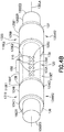
Fig. 4B is a perspective side view of a portion of the force balance sensor ofFig. 3 in accordance with one or more aspects of the present disclosure; -
Fig. 4C is a perspective side view of a portion of the force balance sensor ofFig. 3 in accordance with one or more aspects of the present disclosure; -
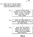
Fig. 5 is a method for controlling a control surface of an aircraft using the force balance sensor ofFig. 2 in accordance with one or more aspects of the present disclosure; and -
Fig. 6 is a flow chart of an aircraft production and service methodology. - Referring to
Figs. 1-3 , the aspects of the present disclosure described herein provide aforce balance sensor 100 which is integral to aflight control surface 1002 and can measure the differential torque (also referred to as force-fight) induced into thecontrol surface 1002 due to, e.g., a difference in applied force at eachactuator force balance sensor 100 is configured such that the mechanical strain of asensor torsion member 110 of theforce balance sensor 100, is increased relative to atorque member 1002T of theflight control surface 1002 to bring an electrical signal (of at least onestrain sensor 120 of the force balance sensor 100), proportional to the torque imbalance of the actuator controllers, above a lower noise threshold of the at least onestrain sensor 120 by increasing the amplitude of the torsional strain on thesensor torsion member 110. The mechanical strain will be a function of the surface stiffness, and for theaircraft 1000, is too low for the at least onestrain sensor 120 to measure due to electrical noise. The aspects of the present disclosure increase the mechanical strain of thesensor torsion member 110 to bring the electrical signal of the at least onestrain sensor 120 above the lower noise threshold by mechanically increasing the amplitude of the torsional strain on thesensor torsion member 110. - As will be described herein, the
force balance sensor 100 is configured to isolate and mechanically increase shear stresses, measure torque difference between, e.g.,actuators control surface 1002, reduce complexity compared to other conventional methods (e.g., by employing fewer sensors and associated electronics), reduce the contribution of sensor error while measuring the torque differential between theactuators - Still referring to
Figs. 1-3 , in one aspect, theforce balance sensor 100 described herein for sensing mechanical strain across at least onecontrol surface 1002 of anaircraft 1000 includes a mechanicalstrain amplification system 130 having asensor torsion member 110, at least onestrain sensor 120, a first torsionalstiffening member stiffening member end coupling member 136, and a second torsion barend coupling member 137. Generally, torsional stiffness of thecontrol surface 1002 is substantial such that any mechanical strain sensed by the at least onestrain sensor 120 is likely to be located within the signal noise (i.e., a low amplitude signal) produced by the at least onestrain sensor 120. In order for the signal produced by the at least onestrain sensor 120 to be usable, the mechanicalstrain amplification system 130 is configured to mechanically increase the signals produced by the at least onestrain sensor 120 so that the sensor signals are above the noise threshold of the at least onestrain sensor 120. - The
force balance sensor 100 is configured so that the at least onestrain sensor 120 senses torsional deflection of thesensor torsion member 110 of the mechanicalstrain amplification system 130, coupled to atorque member 1002T of acontrol surface 1002. The mechanicalstrain amplification system 130 increases the signal sensed by the at least onestrain sensor 120 to an accessible level above the noise threshold (i.e., a level above the noise produced by the at least onestrain sensor 120 so that the signal may be attained). - It is noted that although the
force balance sensor 100 is described herein with respect to torsional deflection of acontrol surface 1002 of the aircraft 1000 (e.g.,flaps 1002F,slats 1002S,ailerons 1002A,elevators 1002E,rudder 1002R, or any other suitable control surface), in other aspects theforce balance sensor 100 may be used in any suitable industry, for example, maritime, automotive, aerospace, etc., where measurement of torsional deflection of a torsion member is desired. It is further noted that while theaircraft 1000 depicted inFig. 1 is depicted as a fixed wing aircraft, in other aspects, the aircraft may be a rotary wing aircraft or any other suitable aircraft. - As illustrated in
Fig. 2 , afirst actuator 1010 is coupled to the first end 1002E1 of thetorque member 1002T. Thefirst actuator 1010 is further coupled to theairframe 1001 in any suitable manner. Asecond actuator 1020 is coupled to the second end 1002E2 of thetorque member 1002T. Thesecond actuator 1020 is also coupled to theairframe 1001 in any suitable manner. Both the first andsecond actuators control surface 1002 about the longitudinal axis 1002LA of thetorque member 1002T. Thetorque member 1002T forms a primary load path or strain path between the twoactuators - In one aspect, the
torque member 1002T is a hollow tube 1002HT (Fig. 3 ) having an interior 1002IT, where the mechanicalstrain amplification system 130 is disposed within the interior 1002IT of the hollow tube 1002HT. In other aspects, the mechanicalstrain amplification system 130 may be coupled to an exterior surface of the hollow tube 1002HT in a manner similar to that described herein with respect toFigs. 4B and4C . The hollow tube 1002HT may be coupled to thecontrol surface 1002 in any suitable manner so that as the hollow tube 1002HT pivots about the longitudinal axis 1002LA, thecontrol surface 1002 pivots with the hollow tube 1002HT as a single unit. In another aspect, thetorque member 1002T is a solid rod 1002SR (i.e., no interior surface,Fig. 4B ) having an exterior 1002ET, where the mechanicalstrain amplification system 130 is disposed on the exterior 1002ET of the solid rod 1002SR (Figs. 4B and4C ). In one aspect, thetorque member 1002T may be a combination of a solid rod and a hollow tube or any other suitable member having any suitable shape. - Still referring to
Figs. 2-4C , as noted above, theforce balance sensor 100 generally includes the mechanicalstrain amplification system 130 having thesensor torsion member 110, the at least onestrain sensor 120, the firsttorsional stiffening member 131, and the secondtorsional stiffening member 132. The mechanicalstrain amplification system 130 is disposed on or within thetorque member 1002T and forms a secondary strain path between the first andsecond actuators strain amplification system 130 generally has a lower stiffness than thetorque member 1002T which forms the primary strain path. - The mechanical
strain amplification system 130 extends a distance D along the longitudinal axis 1002LA of thetorque member 1002T. In one aspect, the distance D may span the entire length of thetorque member 1002T or span any suitable distance along thetorque member 1002T to increase the stiffness of thetorque member 1002T and increase strain in thesensor torsion member 110 as further described herein. The distance D may also generally be related to a material used for one or more of thesensor torsion member 110, the first/secondtorsional stiffening members control surface 1002. - In one aspect, the torsional stiffness of the
torque member 1002T is increased by the mechanicalstrain amplification system 130 such that kt = k1TM + k2MSA, where kt is the total stiffness, k1TM is the torque member stiffness, and k2MSA is the stiffness of the mechanicalstrain amplification system 130. In one aspect, thesensor torsion member 110 forms a torsion bar or tube disposed on or within thetorque member 1002T of thecontrol surface 1002. Thesensor torsion member 110 includes a first end 110E1 and a second end 110E2 spaced from one another along a mechanical strain amplification longitudinal axis 130LA of the mechanicalstrain amplification system 130, which may be coincident with the longitudinal axis 1002LA of thetorque member 1002T. The first end 110E1 and the second end 110E2 are spaced a distance Y (Fig. 3 ) from one another spanning a length of, for example, thecontrol surface 1002. The distance Y may span any suitable length of thecontrol surface 1002. In one aspect, the distance Y may generally be related to a material used for one or more of thetorque member 1002T, the first/secondtorsional stiffening members sensor torsion member 110 and thus a larger or smaller distance Y is necessary to sense torsion on thetorque member 1002T). - In one aspect, the
sensor torsion member 110 is a hollow tube 110HT (Figs. 4B and4C ) having an interior 110IT and an exterior 110ET, where the at least onestrain sensor 120 is disposed on the exterior 110ET of the hollow tube 110HT. The hollow tube 110HT may be coupled to thecontrol surface 1002 in any suitable manner so that astorque member 1002T twists, the hollow tube 110HT twists relative to thecontrol surface 1002. In another aspect, thesensor torsion member 110 may be a solid rod 110SR (i.e., no interior surface) having an exterior 110ET, where the at least onestrain sensor 120 is disposed on the exterior 110ET of the solid rod 110SR. In one aspect, thesensor torsion member 110 may be a combination of a solid rod and a hollow tube or any other suitable member having any suitable shape. Thesensor torsion member 110 is configured to have a material stiffness that is substantially lower than thetorque member 1002T, the firsttorsional stiffening member 131, and the secondtorsional stiffening member 132 as will be further described below. - Still referring to
Figs. 2-4C , the at least onestrain sensor 120 is configured to sense strain exerted on the sensor torsion member 110 (e.g., twisting of the sensor torsion member 110) during, e.g., pivotal movement of thecontrol surface 1002 caused by actuation of the first andsecond actuators strain sensor 120 is disposed within thetorque member 1002T so that thetorque member 1002T forms an electromagnetic shield for the at least one strain sensor 120 (i.e., the at least onestrain sensor 120 is disposed within thetorque member 1002T such that thetorque member 1002T surrounds the at least onestrain sensor 120 forming a Faraday cage to guard or protect the at least onestrain sensor 120 against electromagnetic interference). In one aspect, the at least onestrain sensor 120 may be disposed within thesensor torsion member 110, such as when thesensor torsion member 110 is coupled to the exterior of thetorque member 1002T, so as to electromagnetically shield the at least onestrain sensor 120. - In one aspect, the first
torsional stiffening member 131 is coupled to the first end 110E1 of thesensor torsion member 110. The secondtorsional stiffening member 132 is coupled to the second end 110E2 of thesensor torsion member 110. In one aspect, the firsttorsional stiffening member 131 and the secondtorsional stiffening member 132 each extend over respective predeterminedlongitudinal lengths Fig. 3 ) of thetorque member 1002T. The first and secondtorsional stiffening members torque member 1002T over a length of themechanical amplification system 130. A material stiffness of each of the first and secondtorsional stiffening members sensor torsion member 110 and thetorque member 1002T, while thesensor torsion member 110 has a lower material stiffness compared to thetorque member 1002T and the first and secondtorsional stiffening members - Each of the first and second
torsional stiffening members sensor torsion member 110, increases the torsional stiffness of thesensor torsion member 110 over the respective predeterminedlongitudinal lengths longitudinal lengths sensor torsion member 110 coupled between the first and secondtorsional stiffening members 131, 132 (i.e., the higher material stiffness of the first and secondtorsional stiffening members strain amplification system 130 over the respective predeterminedlongitudinal lengths longitudinal lengths sensor torsion member 110 to mechanically increase the twisting in the sensor torsion member 110). The increase in twist of thesensor torsion member 110 correspondingly mechanically increases strain (i.e., increases the strain above the lower noise threshold of the at least one strain sensor 120) sensed by the at least onestrain sensor 120. - Referring to
Figs. 3 and4A , the first and secondtorsional stiffening members torsional stiffening member 131A shown inFig. 4A however, it should be understood that the second torsional stiffening member is substantially similar and includes similar features. As noted above, the firsttorsional stiffening member 131A and the secondtorsional stiffening member 132A are coupled to thesensor torsion member 110, disposed within the interior 1002IT of thetorque member 1002T. Each of the first and secondtorsional stiffening members second torsion bar second torsion bar Fig. 3 ) or hollow tube 134HT1, 135HT1 (seeFig. 4A ) that is disposed inside thetorque member 1002T. Each of the first andsecond torsion bar first torsion bar 134A and thesecond torsion bar 135A are configured so that the first and secondtorsional stiffening members sensor torsion member 110 and thetorque member 1002T. For example, each of thesensor torsion member 110 and thetorque member 1002T may be formed by a material with a lower material stiffness than thefirst torsion bar 134A and thesecond torsion bar 135A. - In one aspect, a first torsion bar
end coupling member torsion bar end coupling member torque member 1002T so that there is substantially no relative movement between thetorque member 1002T and each of thefirst torsion bar 134A and thesecond torsion bar 135A. - In another aspect, as illustrated in
Fig. 4B and4C , the firsttorsional stiffening member torsional stiffening member torsional stiffening members torsional stiffening member torsional stiffening member torque member 1002T. The first and secondtorsional stiffening members Fig. 4C ) or a hollow tube 134HT2, 135HT2 (Fig. 4B ). - In one aspect, the mechanical
strain amplification system 130 may further include at least onevibration isolators vibration isolators sensor torsion member 110. The at least onevibration isolators sensor torsion member 110 disposed on or within thetorque member 1002T from vibration of thetorque member 1002T. The at least onevibration isolators torque member 1002T such that vibration transfer from thetorque member 1002T to thesensor torsion member 110 is limited or reduced. - Referring now to
Figs. 2 ,3 , and4B , in one aspect, theforce balance sensor 100 further includes at least onesignal amplifier 150 coupled to the at least onestrain sensor 120 and configured to electronically amplify the sensor signals produced by the at least onestrain sensor 120. In one aspect, theforce balance sensor 100 further includes thecontroller 170 coupled to the at least onestrain sensor 120. Thecontroller 170 includes non-transitory computer program code configured to determine a torsional displacement (i.e., twist) between the first end 110E1 and the second end 110E2 of thesensor torsion member 110 based on sensor signals received from the at least onestrain sensor 120. Thecontroller 170 is further configured to correct the torsional displacement via actuation of the first andsecond actuators - In one aspect, the first torsion bar
end coupling member second torsion bar Fig. 4A ). Theaperture 145 is configured for passingwires electrical power wires 180W, such as for providingelectrical power 180 to the at least onesignal amplifier 150 and the at least onestrain sensor 120, may pass through one or more of the first torsion barend coupling member end coupling member Signal wires 170W, such as for providing the sensor signals from the at least onestrain sensor 120 and the at least onesignal amplifier 150 to thecontroller 170, may also pass through the first torsion barend coupling member power wires 180W and thesignal wires 170W may be disposed on opposite sides of, at least thesignal amplifier 150 so as to substantially prevent electromagnetic interference between thepower wires 180W and thesignal wires 170W. As an example, thepower 180 is provided via thepower wires 180W at the side 1002SS2 of thecontrol surface 1002 while the sensor signals are transmitted via thewires 170W at the side 1002SS1. In another aspect,electrical power 180 to and sensor signals from the at least onestrain sensor 120 and the at least onesignal amplifier 150 may be provided in any suitable manner. For example, where thetorque member 1002T is solid, thewires signal amplifier 150 and the at least onestrain sensor 120 external to thetorque member 1002T and the first and secondtorsional stiffening members - Referring now to
Fig. 5 , amethod 400 for controlling thecontrol surface 1002 of theaircraft 1000 using theforce balance sensor 100 is illustrated. In one aspect, thefirst actuator 1010 and thesecond actuator 1020 are actuated by thecontroller 170 so as to pivot thecontrol surface 1002 relative to theairframe 1001 about the longitudinal axis 1002LA of thetorque member 1002T (Fig. 5 , Block 401). - During and/or after the
control surface 1002 pivots, theforce balance sensor 100 senses strain exerted on the sensor torsion member 110 (Fig. 5 , Block 402) with the at least onestrain sensor 120 coupled to thesensor torsion member 110 between the first 110E1 and second ends 110E2. In one aspect, the firsttorsional stiffening member 131 and the secondtorsional stiffening member 132 increase a torsional stiffness of thetorque member 1002T so that the twisting of thesensor torsion member 110 mechanically increases strain sensed by the at least onestrain sensor 120. - In one aspect, the sensor signals, corresponding to the mechanically increased strain, sensed by the at least one
strain sensor 120 are further amplified by at least onesignal amplifier 150 and transmitted to thecontroller 170. Based on the mechanically increased strain sensed by the at least onesensor 120, the position of thefirst actuator 1010 and thesecond actuator 1020 may be adjusted with the controller 170 (Fig. 5 , Block 403). Adjusting the position of the first andsecond actuators sensor torsion member 110, and thus thecontrol surface 1002 to a level below a predetermined strain threshold. - The
controller 170 is configured to receive signals from as many sensors as are implemented in thesensor torsion member 110. For example, if more than onesensor Fig. 4B ), such as for triple redundancy, are installed and providing signals to thecontroller 170, thecontroller 170 is configured to determine which sensor signal or combination of sensor signals to use for balancing the force between the twoactuators controller 170 in any suitable manner, such as by taking an average of the sensor signals, discarding one or more sensor signals if the one or more sensor signals differs from other ones of the sensor signals by a predefined limit, etc. If one sensor signal differs from the others beyond the predefined limit, thecontroller 170 may be configured to notify an operator of theaircraft 1000 or other personnel that there may be anomalous sensor readings from theforce balance sensor 100 for diagnostics and prognostics. - Once the selected signal(s) is applied by the
controller 170 to correct the torsional difference between the twoactuators controller 170 may substantially continuously adjust a position of one or more of theactuators controller 170 from the at least one strain sensor 120 (or the at least one signal amplifier 150) indicates that the difference in torque between the twoactuators actuator actuators actuators actuator - In one aspect, vibration of the
sensor torsion member 110 is dampened with at least onevibration isolator - In one aspect, the
torque member 1002T shields the at least onestrain sensor 120 from electromagnetic effects (Fig. 5 , Block 404). - Examples of the present disclosure may be described in the context of aircraft manufacturing and
service method 500 as shown inFig. 6 . In other aspects, the examples of the present disclosure may be applied in any suitable industry, such as e.g., automotive, maritime, aerospace, etc. With respect to aircraft manufacturing, during pre-production,illustrative method 500 may include specification and design (block 501) of aircraft 1000 (Fig. 1 ) and material procurement (block 502). During production, component and subassembly manufacturing (block 503) and system integration (block 504) ofaircraft 1000 may take place. Thereafter,aircraft 1000 may go through certification and delivery (block 505) to be placed in service (block 506). While in service,aircraft 1000 may be scheduled for routine maintenance and service (block 507). Routine maintenance and service may include modification, reconfiguration, refurbishment, etc. of one or more systems ofaircraft 1000 which may include use of theforce balance sensor 100 as described herein. - Each of the processes of
illustrative method 500 may be performed or carried out by a system integrator, a third party, and/or an operator (e.g., a customer). For the purposes of this description, a system integrator may include, without limitation, any number of aircraft manufacturers and major-system subcontractors; a third party may include, without limitation, any number of vendors, subcontractors, and suppliers; and an operator may be an airline, leasing company, military entity, service organization, and so on. - Apparatus(es) and method(s) shown or described herein may be employed during any one or more of the stages of the manufacturing and
service method 500. For example, components or subassemblies corresponding to component and subassembly manufacturing (block 503) may be fabricated or manufactured in a manner similar to components or subassemblies produced whileaircraft 1000 is in service (block 506). Also, one or more examples of the apparatus(es), method(s), or combination thereof may be utilized duringproduction stages aircraft 1000. Similarly, one or more examples of the apparatus or method realizations, or a combination thereof, may be utilized, for example and without limitation, whileaircraft 1000 is in service (block 506) and/or during maintenance and service (block 507) . - The following are provided in accordance with the aspects of the present disclosure:
- A1. A force balance sensor including:
- a mechanical strain amplification system including:
- a sensor torsion member having a first end and a second end spaced from one another along a longitudinal axis of the sensor torsion member;
- at least one strain sensor coupled to the sensor torsion member between the first and second ends;
- a first torsional stiffening member coupled to the first end of the sensor torsion member; and
- a second torsional stiffening member coupled to the second end of the sensor torsion member,
- wherein the first torsional stiffening member and the second torsional stiffening member are coupled to a torque member.
- a mechanical strain amplification system including:
- A2. The paragraph of A1, wherein torque is transferred from the torque member to the sensor torsion member by the first and second torsional stiffening members so as to mechanically increase strain sensed by the at least one strain sensor.
- A3. The paragraph of A1 or A2, wherein the first and second torsional stiffening members increase a torsional stiffness of the torque member over a length of the mechanical strain amplification system, where twisting of the sensor torsion member disposed between the first and second torsional stiffening members, due to differential torsional forces applied at opposite ends of the torque member, is increased relative to twisting of the torque member over the length of the mechanical amplification system so as to mechanically increase strain sensed by the at least one strain sensor.
- A4. The paragraph of any of A1 to A3, wherein the torque member comprises a hollow tube having an interior, where one or more of the at least one strain sensor, the first torsional stiffening member, and the second torsional stiffening member are disposed within the interior.
- A5. The paragraph of any of A1 to A4, wherein one or more of the at least one strain sensor, the first torsional stiffening member, and the second torsional stiffening member are disposed on an exterior of the torque member.
- A6. The paragraph of any of A1 to A5, wherein each of the first torsional stiffening member and the second torsional stiffening member comprises:
- a torsion bar having a first torsion bar end and a second torsion bar end separated from each other along a mechanical strain amplification system longitudinal axis; and
- a first torsion bar end coupling member disposed at the first torsion bar end and being configured to fixedly couple the first torsion bar end to the torque member;
- wherein the second torsion bar end is configured to fixedly couple to the sensor torsion member.
- A7. The paragraph of any of A1 to A6, wherein a material stiffness of each of the first torsional stiffening member and the second torsional stiffening member is higher than a material stiffness of both the sensor torsion member and the torque member.
- A8. The paragraph of any of A1 to A7, further comprising at least one signal amplifier coupled to the at least one strain sensor.
- A9. The paragraph of any of A1 to A8, further comprising a controller coupled to the at least one strain sensor, the controller being configured to determine a torsional displacement between the first end and the second end of the sensor torsion member based on sensor signals received from the at least one strain sensor.
- A10. The paragraph of any of A1 to A9, wherein strain sensed by the at least one strain sensor is mechanically increased so that the strain sensed by the at least one strain sensor effects a signal from the at least one strain sensor that is above a noise threshold of the at least one strain sensor.
- A11. The paragraph of any of A1 to A10, wherein the at least one strain sensor is coupled to the sensor torsion member so that the torque member forms an electromagnetic shield for the at least one strain sensor.
- A12. The paragraph of any of A1 to A11, wherein a torque member torsional stiffness is increased by the mechanical strain amplification system such that kt = k1TM + k2MSA, where kt is a total stiffness, k1TM is a torque member stiffness, and k2MSA is a stiffness of the mechanical strain amplification system.
- B1. An aircraft comprising:
- an airframe;
- a control surface having a control surface frame pivotally coupled to the airframe with a torque member;
- a first actuator coupled to the first end and being configured to pivot the control surface about the longitudinal axis;
- a second actuator coupled to the second end and being configured to pivot the control surface about the longitudinal axis;
- a force balance sensor including
- a mechanical strain amplification system including
- a sensor torsion member having a first end and a second end spaced from one another along a longitudinal axis of the sensor torsion member,
- at least one strain sensor coupled to the sensor torsion member between the first and second ends,
- a first torsional stiffening member coupled to the first end of the sensor torsion member, and
- a second torsional stiffening member coupled to the second end of the sensor torsion member,
- wherein the first torsional stiffening member and the second torsional stiffening member are coupled to the torque member of the control surface.
- B2. The paragraph of B1, wherein the torque member comprises a hollow tube having an interior, where one or more of the at least one strain sensor, the first torsional stiffening member, and the second torsional stiffening member are disposed within the interior.
- B3. The paragraph of B1 or B2, wherein one or more of the at least one strain sensor, the first torsional stiffening member, and the second torsional stiffening member are disposed on an exterior of the torque member.
- B4. The paragraph of any of B1 to B3, wherein each of the first torsional stiffening member and the second torsional stiffening member comprises:
- a torsion bar having a first torsion bar end and a second torsion bar end separated from each other along the longitudinal axis of the sensor torsion member; and
- a first torsion bar end coupling member disposed at the first torsion bar end and being configured to fixedly couple the first torsion bar end to the torque member;
- wherein the second torsion bar end is configured to fixedly couple to the sensor torsion member.
- B5. The paragraph of any of B1 to B4, wherein a material stiffness of each of the first torsional stiffening member and the second torsional stiffening member is higher than a material stiffness of both the sensor torsion member and the torque member.
- B6. The paragraph of any of B1 to B5, further comprising at least one signal amplifier coupled to the at least one strain sensor.
- B7. The paragraph of any of B1 to B6, further comprising a controller coupled to the at least one strain sensor, the first actuator, and the second actuator, the controller being configured to:
- determine a torsional displacement between the first end and the second end of the sensor torsion member based on sensor signals received from the at least one strain sensor; and
- actuate one or more of the first actuator and the second actuator so that the twisting of the torque member is reduced and the sensor signals received from the at least one strain sensor are below a predetermined strain threshold.
- B8. The paragraph of any of B1 to B7, wherein strain sensed by the at least one strain sensor is mechanically increased so that the strain sensed by the at least one strain sensor effects a signal from the at least one strain sensor that is above a noise threshold of the at least one strain sensor.
- B9. The paragraph of any of B1 to B8, wherein the at least one strain sensor is coupled to the sensor torsion member so that the torque member forms an electromagnetic shield for the at least one strain sensor.
- B10. The paragraph of any of B1 to B9, wherein a torque member torsional stiffness is increased by the mechanical strain amplification system such that kt = k1TM + k2MSA, where kt is a total stiffness, k1TM is a torque member stiffness, and k2MSA is a stiffness of the mechanical strain amplification system.
- B11. The paragraph of any of B1 to B10, further comprising:
- a controller coupled to the at least one strain sensor through a first coupling; and
- a power source coupled to the at least one strain sensor through a second coupling, where the first coupling extends through the first end of the torque member and the second coupling extends through the second end of the torque member so as to mitigate electromagnetic effects on a sensor signal generated by the at least one strain sensor.
- C1. A method for controlling a control surface of an aircraft, the method comprising:
- actuating a first actuator and a second actuator with a controller so as to pivot the control surface relative to the airframe about a longitudinal axis of a torque member, where
- the torque member pivotally couples a control surface frame of the control surface to the airframe, and
- the first actuator and the second actuator are coupled to the torque member at respective opposite ends of the torque member for pivoting the control surface;
- sensing strain on the torque member with a force balance sensor disposed between the opposite ends of the torque member, the force balance sensor including a mechanical strain amplification system including a sensor torsion member, at least one strain sensor coupled to the sensor torsion member between a first end and a second end of the sensor torsion member, a first torsional stiffening member coupled to the first end of the sensor torsion member and the torque member, and a second torsional stiffening member coupled to the second end of the sensor torsion member and the torque member; and
- adjusting actuation of one or more of the first actuator and the second actuator, with the controller, based on mechanically increased strain sensed by the at least one sensor.
- C2. The paragraph of C1, where the first torsional stiffening member and the second torsional stiffening member extend over respective predetermined longitudinal lengths of the mechanical strain amplification system and increase a torsional stiffness of the torque member over the respective predetermined lengths so that the twisting of the sensor torsion member disposed between the first torsional stiffening member and the second torsional stiffening member, due to differential torsional forces applied at the first end and second end of the sensor torsion member by the first actuator and the second actuator, is increased relative to twisting of the torque member over the length of the mechanical strain amplification system so as to mechanically increase strain sensed by the at least one strain sensor.
- C3. The paragraph of C1 or C2, wherein a material stiffness of each of the first torsional stiffening member and the second torsional stiffening member is higher than a material stiffness of both the sensor torsion member and the torque member.
- C4. The paragraph of any of C1 to C3, wherein the sensor signals, corresponding to the mechanically increased strain, sensed by the at least one sensor are amplified by at least one signal amplifier for transmission to the controller.
- C5. The paragraph of any of C1 to C4, wherein strain sensed by the at least one strain sensor is mechanically increased so that the strain sensed by the at least one strain sensor effects the sensor signals from the at least one strain sensor having a signal amplitude that is above a noise threshold of the at least one strain sensor.
- C6. The paragraph of any of C1 to C5, further comprising shielding, with the torque member, the at least one strain sensor from electromagnetic effects.
- In the figures, referred to above, solid lines, if any, connecting various elements and/or components may represent mechanical, electrical, fluid, optical, electromagnetic, wireless and other couplings and/or combinations thereof. As used herein, "coupled" means associated directly as well as indirectly. For example, a member A may be directly associated with a member B, or may be indirectly associated therewith, e.g., via another member C. It will be understood that not all relationships among the various disclosed elements are necessarily represented. Accordingly, couplings other than those depicted in the drawings may also exist. Dashed lines, if any, connecting blocks designating the various elements and/or components represent couplings similar in function and purpose to those represented by solid lines; however, couplings represented by the dashed lines may either be selectively provided or may relate to alternative examples of the present disclosure. Likewise, elements and/or components, if any, represented with dashed lines, indicate alternative examples of the present disclosure. One or more elements shown in solid and/or dashed lines may be omitted from a particular example without departing from the scope of the present disclosure. Environmental elements, if any, are represented with dotted lines. Virtual (imaginary) elements may also be shown for clarity. Those skilled in the art will appreciate that some of the features illustrated in the figures, may be combined in various ways without the need to include other features described in the figures, other drawing figures, and/or the accompanying disclosure, even though such combination or combinations are not explicitly illustrated herein. Similarly, additional features not limited to the examples presented, may be combined with some or all of the features shown and described herein.
- In
Figs. 5 and6 , referred to above, the blocks may represent operations and/or portions thereof and lines connecting the various blocks do not imply any particular order or dependency of the operations or portions thereof. Blocks represented by dashed lines indicate alternative operations and/or portions thereof. Dashed lines, if any, connecting the various blocks represent alternative dependencies of the operations or portions thereof. It will be understood that not all dependencies among the various disclosed operations are necessarily represented.Figs. 5 and6 and the accompanying disclosure describing the operations of the method(s) set forth herein should not be interpreted as necessarily determining a sequence in which the operations are to be performed. Rather, although one illustrative order is indicated, it is to be understood that the sequence of the operations may be modified when appropriate. Accordingly, certain operations may be performed in a different order or substantially simultaneously. Additionally, those skilled in the art will appreciate that not all operations described need be performed. - In the following description, numerous specific details are set forth to provide a thorough understanding of the disclosed concepts, which may be practiced without some or all of these particulars. In other instances, details of known devices and/or processes have been omitted to avoid unnecessarily obscuring the disclosure. While some concepts will be described in conjunction with specific examples, it will be understood that these examples are not intended to be limiting.
- Unless otherwise indicated, the terms "first," "second," etc. are used herein merely as labels, and are not intended to impose ordinal, positional, or hierarchical requirements on the items to which these terms refer. Moreover, reference to, e.g., a "second" item does not require or preclude the existence of, e.g., a "first" or lower-numbered item, and/or, e.g., a "third" or higher-numbered item.
- Reference herein to "one example" means that one or more feature, structure, or characteristic described in connection with the example is included in at least one implementation. The phrase "one example" in various places in the specification may or may not be referring to the same example.
- As used herein, a system, apparatus, structure, article, element, component, or hardware "configured to" perform a specified function is indeed capable of performing the specified function without any alteration, rather than merely having potential to perform the specified function after further modification. In other words, the system, apparatus, structure, article, element, component, or hardware "configured to" perform a specified function is specifically selected, created, implemented, utilized, programmed, and/or designed for the purpose of performing the specified function. As used herein, "configured to" denotes existing characteristics of a system, apparatus, structure, article, element, component, or hardware which enable the system, apparatus, structure, article, element, component, or hardware to perform the specified function without further modification. For purposes of this disclosure, a system, apparatus, structure, article, element, component, or hardware described as being "configured to" perform a particular function may additionally or alternatively be described as being "adapted to" and/or as being "operative to" perform that function.
- Different examples of the apparatus(es) and method(s) disclosed herein include a variety of components, features, and functionalities. It should be understood that the various examples of the apparatus(es) and method(s) disclosed herein may include any of the components, features, and functionalities of any of the other examples of the apparatus(es) and method(s) disclosed herein in any combination, and all of such possibilities are intended to be within the scope of the present disclosure.
- Many modifications of examples set forth herein will come to mind to one skilled in the art to which the present disclosure pertains having the benefit of the teachings presented in the foregoing descriptions and the associated drawings.
- The disclosure comprises the subject matter described in the following clauses:
- Clause 1. A force balance sensor comprising:
- a mechanical strain amplification system comprising:
- a sensor torsion member having a first end and a second end spaced from one another along a longitudinal axis of the sensor torsion member;
- at least one strain sensor coupled to the sensor torsion member between the first and second ends;
- a first torsional stiffening member coupled to the first end of the sensor torsion member; and
- a second torsional stiffening member coupled to the second end of the sensor torsion member,
- wherein the first torsional stiffening member and the second torsional stiffening member are coupled to a torque member.
- a mechanical strain amplification system comprising:
- Clause 2. The force balance sensor of clause 1, wherein torque is transferred from the torque member to the sensor torsion member by the first and second torsional stiffening members so as to mechanically increase strain sensed by the at least one strain sensor.
- Clause 3. The force balance sensor of clause 1 or clause 2, wherein:
- the first and second torsional stiffening members increase a torsional stiffness of the torque member over a length of the mechanical strain amplification system; and
- twisting of the sensor torsion member disposed between the first and second torsional stiffening members, due to differential torsional forces applied at opposite ends of the torque member, is increased relative to twisting of the torque member over the length of the mechanical amplification system so as to mechanically increase strain sensed by the at least one strain sensor.
- Clause 4. The force balance sensor of any preceding clause, wherein each of the first torsional stiffening member and the second torsional stiffening member comprises:
- a torsion bar having a first torsion bar end and a second torsion bar end, the first torsion bar end and the second torsion bar end being separated from each other along a mechanical strain amplification system longitudinal axis; and
- a first torsion bar end coupling member disposed at the first torsion bar end and being configured to fixedly couple the first torsion bar end to the torque member;
- wherein the second torsion bar end is configured to fixedly couple to the sensor torsion member.
- Clause 5. The force balance sensor of any preceding clause, wherein a material stiffness of each of the first torsional stiffening member and the second torsional stiffening member is higher than a material stiffness of both the sensor torsion member and the torque member.
- Clause 6. The force balance sensor of any preceding clause, further comprising at least one signal amplifier coupled to the at least one strain sensor.
-
Clause 7. The force balance sensor of any preceding clause, further comprising a controller coupled to the at least one strain sensor, the controller being configured to determine a torsional displacement between the first end and the second end of the sensor torsion member based on sensor signals received from the at least one strain sensor. - Clause 8. The force balance sensor of any preceding clause, wherein strain sensed by the at least one strain sensor is mechanically increased so that the strain sensed by the at least one strain sensor effects a signal from the at least one strain sensor that is above a noise threshold of the at least one strain sensor.
- Clause 9. The force balance sensor of any preceding clause, wherein the at least one strain sensor is coupled to the sensor torsion member so that the torque member forms an electromagnetic shield for the at least one strain sensor.
- Clause 10. An aircraft comprising:
- an airframe;
- a control surface having a control surface frame pivotally coupled to the airframe with a torque member;
- a first actuator coupled to the first end and being configured to pivot the control surface about the longitudinal axis;
- a second actuator coupled to the second end and being configured to pivot the control surface about the longitudinal axis; and
- a force balance sensor comprising:
a mechanical strain amplification system comprising:- a sensor torsion member having a first end and a second end spaced from one another along a longitudinal axis of the sensor torsion member;
- at least one strain sensor coupled to the sensor torsion member between the first and second ends;
- a first torsional stiffening member coupled to the first end of the sensor torsion member; and
- a second torsional stiffening member coupled to the second end of the sensor torsion member,
- wherein the first torsional stiffening member and the second torsional stiffening member are coupled to the torque member of the control surface.
- Clause 11. The aircraft of clause 10, wherein torque is transferred from the torque member to the sensor torsion member by the first and second torsional stiffening members so as to mechanically increase strain sensed by the at least one strain sensor.
- Clause 12. The aircraft of clause 10 or clause 11, wherein:
- the first and second torsional stiffening members increase a torsional stiffness of the torque member over a length of the mechanical strain amplification system; and
- twisting of the sensor torsion member disposed between the first and second torsional stiffening members, due to differential torsional forces applied at opposite ends of the torque member, is increased relative to twisting of the torque member over the length of the mechanical amplification system so as to mechanically increase strain sensed by the at least one strain sensor.
- Clause 13. The aircraft of any of clauses 10 to 12, wherein one or more of the sensor torsion member, the at least one strain sensor, the first torsional stiffening member, and the second torsional stiffening member are disposed within an interior or on an exterior of the torque member.
- Clause 14. The aircraft of any of clauses 10 to 13, wherein each of the first torsional stiffening member and the second torsional stiffening member comprises:
- a torsion bar having a first torsion bar end and a second torsion bar end, the first torsion bar end and the second torsion bar end being separated from each other along the longitudinal axis of the sensor torsion member; and
- a first torsion bar end coupling member disposed at the first torsion bar end and being configured to fixedly couple the first torsion bar end to the torque member;
- wherein the second torsion bar end is configured to fixedly couple to the sensor torsion member.
- Clause 15. The aircraft of any of clauses 10 to 14, further comprising a controller coupled to the at least one strain sensor, the first actuator, and the second actuator, the controller being configured to:
- determine a torsional displacement between the first end and the second end of the sensor torsion member based on sensor signals received from the at least one strain sensor; and
- actuate one or more of the first actuator and the second actuator so that the twisting of the torque member is reduced and the sensor signals received from the at least one strain sensor are below a predetermined strain threshold.
- Clause 16. The aircraft of any of clauses 10 to 15, wherein a torque member torsional stiffness is increased by the mechanical strain amplification system such that kt = k1TM + k2MSA, where kt is a total stiffness, k1TM is a torque member stiffness, and k2MSA is a stiffness of the mechanical strain amplification system.
- Clause 17. The aircraft of any of clauses 10 to 16, further comprising:
- a controller coupled to the at least one strain sensor through a first coupling; and
- a power source coupled to the at least one strain sensor through a second coupling, where the first coupling extends through the first end of the torque member and the second coupling extends through the second end of the torque member so as to mitigate electromagnetic effects on a sensor signal generated by the at least one strain sensor.
- Clause 18. A method for controlling a control surface of an aircraft, the method comprising:
- actuating a first actuator and a second actuator with a controller so as to pivot the control surface relative to the airframe about a longitudinal axis of a torque member, wherein the torque member pivotally couples a control surface frame of the control surface to the airframe, and the first actuator and the second actuator are coupled to the torque member at respective opposite ends of the torque member for pivoting the control surface;
- sensing strain on the torque member with a force balance sensor disposed between the opposite ends of the torque member, the force balance sensor comprising:
a mechanical strain amplification system comprising:- a sensor torsion member;
- at least one strain sensor coupled to the sensor torsion member between a first end and a second end of the sensor torsion member;
- a first torsional stiffening member coupled to the first end of the sensor torsion member and the torque member;
- and a second torsional stiffening member coupled to the second end of the sensor torsion member and the torque member; and
- adjusting actuation of one or more of the first actuator and the second actuator, with the controller, based on mechanically increased strain sensed by the at least one sensor.
- Clause 19. The method of clause 18, where the first torsional stiffening member and the second torsional stiffening member extend over respective predetermined longitudinal lengths of the mechanical strain amplification system and increase a torsional stiffness of the torque member over the respective predetermined lengths so that the twisting of the sensor torsion member disposed between the first torsional stiffening member and the second torsional stiffening member, due to differential torsional forces applied at the first end and second end of the sensor torsion member by the first actuator and the second actuator, is increased relative to twisting of the torque member over the length of the mechanical strain amplification system so as to mechanically increase strain sensed by the at least one strain sensor.
- Clause 20. The method of clause 18 or clause 19, wherein the sensor signals, corresponding to the mechanically increased strain, sensed by the at least one sensor are amplified by at least one signal amplifier for transmission to the controller.
- Clause 21. The method of any of clauses 18 to 20, wherein strain sensed by the at least one strain sensor is mechanically increased so that the strain sensed by the at least one strain sensor effects the sensor signals from the at least one strain sensor having a signal amplitude that is above a noise threshold of the at least one strain sensor.
- Clause 22. The method of any of clauses 18 to 21, further comprising shielding, with the torque member, the at least one strain sensor from electromagnetic effects.
- Clause 23. An aircraft comprising the force balance sensor of any of clauses 1 to 9.
- Therefore, it is to be understood that the present disclosure is not to be limited to the specific examples illustrated and that modifications and other examples are intended to be included within the scope of the appended claims. Moreover, although the foregoing description and the associated drawings describe examples of the present disclosure in the context of certain illustrative combinations of elements and/or functions, it should be appreciated that different combinations of elements and/or functions may be provided by alternative implementations without departing from the scope of the appended claims. Accordingly, parenthetical reference numerals in the appended claims are presented for illustrative purposes only and are not intended to limit the scope of the claimed subject matter to the specific examples provided in the present disclosure.
Claims (15)
- A force balance sensor (100) comprising:a mechanical strain amplification system (130) comprising:a sensor torsion member (110) having a first end (110a) and a second end (110b) spaced from one another along a longitudinal axis (110LA) of the sensor torsion member (110);at least one strain sensor (120) coupled to the sensor torsion member (110) between the first and second ends (110a/110b);a first torsional stiffening member (131) coupled to the first end (110a) of the sensor torsion member (110); anda second torsional stiffening member (132) coupled to the second end (110b) of the sensor torsion member (110),wherein the first torsional stiffening member (131) and the second torsional stiffening member (132) are coupled to a torque member (1002T).
- The force balance sensor (100) of claim 1, wherein torque is transferred from the torque member (1002T) to the sensor torsion member (110) by the first and second torsional stiffening members (131/132) so as to mechanically increase strain sensed by the at least one strain sensor (120).
- The force balance sensor (100) of claim 1 or claim 2, wherein:the first and second torsional stiffening members (131/132) increase a torsional stiffness of the torque member (1002T) over a length of the mechanical strain amplification system (130);and twisting of the sensor torsion member (110) disposed between the first and second torsional stiffening members (131/132), due to differential torsional forces applied at opposite ends (1002E1/1002E2) of the torque member (1002T), is increased relative to twisting of the torque member (1002T) over the length of the mechanical strain amplification system (130) so as to mechanically increase strain sensed by the at least one strain sensor (120).
- The force balance sensor (100) of any of claims 1 to 3, wherein each of the first torsional stiffening member (131) and the second torsional stiffening member (132) comprises:a torsion bar (134) having a first torsion bar end (134E1) and a second torsion bar end (134E2) separated from each other along a mechanical strain amplification system (130) longitudinal axis (110LA); anda first torsion bar end coupling member (136) disposed at the first torsion bar end (134E1) and being configured to fixedly couple the first torsion bar end (134E1) to the torque member (1002T);wherein the second torsion bar end (134E2) is configured to fixedly couple to the sensor torsion member (110).
- The force balance sensor (100) of any of claims 1 to 4, wherein a material stiffness of each of the first torsional stiffening member (131) and the second torsional stiffening member (132) is higher than a material stiffness of both the sensor torsion member (110) and the torque member (1002T).
- The force balance sensor (100) of any of claims 1 to 5, further comprising at least one signal amplifier (150) coupled to the at least one strain sensor (120).
- The force balance sensor (100) of any of claims 1 to 6, further comprising a controller (170) coupled to the at least one strain sensor (120), the controller (170) being configured to determine a torsional displacement between the first end (110a) and the second end (110b) of the sensor torsion member (110) based on sensor signals received from the at least one strain sensor (120) .
- The force balance sensor (100) of any of claims 1 to 7, wherein strain sensed by the at least one strain sensor (120) is mechanically increased so that the strain sensed by the at least one strain sensor (120) effects a signal from the at least one strain sensor (120) that is above a noise threshold of the at least one strain sensor (120).
- The force balance sensor (100) of any of claims 1 to 8, wherein the at least one strain sensor (120) is coupled to the sensor torsion member (110) so that the torque member (1002T) forms an electromagnetic shield for the at least one strain sensor (120) .
- An aircraft comprising:the force balance sensor (100) of any of claims 1 to 9.
- A method for controlling a control surface (1002) of an aircraft (1000), the method comprising:actuating a first actuator (1010) and a second actuator (1020) with a controller (170) so as to pivot the control surface (1002) relative to the airframe (1001) about a longitudinal axis (110LA) of a torque member (1002T), where the torque member (1002T) pivotally couples a control surface frame of the control surface (1002) to the airframe (1001), and the first actuator (1001) and the second actuator (1002) are coupled to the torque member (1002T) at respective opposite ends of the torque member (1002T) for pivoting the control surface (1002);sensing strain on the torque member (1002T) with a force balance sensor (100) disposed between the opposite ends of the torque member (1002T), the force balance sensor (100) comprising:a mechanical strain amplification system (130) comprising:a sensor torsion member (110);at least one strain sensor (120) coupled to the sensor torsion member (110) between a first end (110a) and a second end (110b) of the sensor torsion member (110);a first torsional stiffening member (131) coupled to the first end (110a) of the sensor torsion member (110) and the torque member (1002T); anda second torsional stiffening member (132) coupled to the second end (110b) of the sensor torsion member (110) and the torque member (1002T); andadjusting actuation of one or more of the first actuator (1001) and the second actuator (1002), with the controller (170), based on mechanically increased strain sensed by the at least one strain sensor (120).
- The method of claim 11, where the first torsional stiffening member (131) and the second torsional stiffening member (132) extend over respective predetermined longitudinal lengths of the mechanical strain amplification system (130) and increase a torsional stiffness of the torque member (1002T) over the respective predetermined lengths so that the twisting of the sensor torsion member (110) disposed between the first torsional stiffening member (131) and the second torsional stiffening member (132), due to differential torsional forces applied at the first end (110a) and second end (110b) of the sensor torsion member (110) by the first actuator (1001) and the second actuator (1002), is increased relative to twisting of the torque member (1002T) over the length of the mechanical strain amplification system (130) so as to mechanically increase strain sensed by the at least one strain sensor (120).
- The method of claim 11 or claim 12, wherein the sensor signals, corresponding to the mechanically increased strain, sensed by the at least one strain sensor (120) are amplified by at least one signal amplifier (150) for transmission to the controller (170) .
- The method of any of claims 11 to 13, wherein strain sensed by the at least one strain sensor (120) is mechanically increased so that the strain sensed by the at least one strain sensor (120) effects the sensor signals from the at least one strain sensor (120) having a signal amplitude that is above a noise threshold of the at least one strain sensor (120).
- The method of any of claims 11 to 14, further comprising shielding, with the torque member (1002T), the at least one strain sensor (120) from electromagnetic effects.
Applications Claiming Priority (1)
| Application Number | Priority Date | Filing Date | Title |
|---|---|---|---|
| US15/881,237 US10948365B2 (en) | 2018-01-26 | 2018-01-26 | Force balance sensor and method therefor |
Publications (3)
| Publication Number | Publication Date |
|---|---|
| EP3517915A2 true EP3517915A2 (en) | 2019-07-31 |
| EP3517915A3 EP3517915A3 (en) | 2019-11-20 |
| EP3517915B1 EP3517915B1 (en) | 2024-05-29 |
Family
ID=65236895
Family Applications (1)
| Application Number | Title | Priority Date | Filing Date |
|---|---|---|---|
| EP19153771.1A Active EP3517915B1 (en) | 2018-01-26 | 2019-01-25 | Force balance sensor and method therefor |
Country Status (4)
| Country | Link |
|---|---|
| US (1) | US10948365B2 (en) |
| EP (1) | EP3517915B1 (en) |
| JP (1) | JP2019164120A (en) |
| CN (1) | CN110077574B (en) |
Families Citing this family (2)
| Publication number | Priority date | Publication date | Assignee | Title |
|---|---|---|---|---|
| CN110562437B (en) * | 2019-09-19 | 2021-10-22 | 中国商用飞机有限责任公司北京民用飞机技术研究中心 | an aircraft operating device |
| EP4029776B1 (en) | 2021-01-18 | 2026-04-29 | Goodrich Actuation Systems SAS | Actuator control for force fight mitigation |
Family Cites Families (28)
| Publication number | Priority date | Publication date | Assignee | Title |
|---|---|---|---|---|
| US3555894A (en) * | 1966-04-25 | 1971-01-19 | Westinghouse Electric Corp | Strain gauge transducer apparatus |
| US3576302A (en) * | 1968-07-10 | 1971-04-27 | Bendix Corp | Solid-state position sensor for sensing an adjusted position of a control element |
| US3717029A (en) * | 1968-10-23 | 1973-02-20 | Himmelstein & Co S | Torquemeter |
| GB1266973A (en) | 1969-08-22 | 1972-03-15 | ||
| US4800798A (en) | 1984-12-11 | 1989-01-31 | The United States Of America As Represented By The Secretary Of The Air Force | Control surface dual redundant servomechanism |
| JPS61247932A (en) | 1985-04-26 | 1986-11-05 | Matsushita Electric Ind Co Ltd | Torque sensor |
| US4779822A (en) * | 1986-05-23 | 1988-10-25 | Sundstrand Corporation | Actuator system |
| DD252241A1 (en) * | 1986-08-20 | 1987-12-09 | Verlade Transportanlagen | FORCE MEASURING AXIS |
| JPH0620990Y2 (en) * | 1987-04-14 | 1994-06-01 | ▲こう▼娥 ▲高▼楊 | Road cell for civil engineering |
| US4825748A (en) * | 1987-07-02 | 1989-05-02 | Parker-Hannifin Corporation | Hydraulic actuator synchronization apparatus and system |
| JPH01312203A (en) | 1988-06-09 | 1989-12-18 | Hiroshi Sato | Synchronously operated actuator |
| JPH049631A (en) * | 1990-04-27 | 1992-01-14 | Nippon Oil & Fats Co Ltd | Device for measuring strain |
| DE9012718U1 (en) * | 1990-09-06 | 1990-11-08 | Beier, Edgar, 7082 Oberkochen | Non-contact measuring device for torque and/or angle of rotation |
| US6439066B1 (en) * | 1996-08-14 | 2002-08-27 | Peter Norton | Torque sensor |
| US7834494B2 (en) * | 2004-06-04 | 2010-11-16 | The Boeing Company | Fault-tolerant electromechanical actuator having a torque sensing control system |
| JP2006220574A (en) * | 2005-02-14 | 2006-08-24 | Hitachi Ltd | Rotor dynamic quantity measuring device and rotary dynamic quantity measuring system |
| US20090007696A1 (en) * | 2007-07-05 | 2009-01-08 | Nitta Corporation | Strain gauge type sensor |
| US20090302516A1 (en) * | 2008-06-05 | 2009-12-10 | Lockheed Martin Corporation | System, method and apparatus for control surface with dynamic compensation |
| DE102008052754A1 (en) * | 2008-10-22 | 2010-05-06 | Airbus Deutschland Gmbh | Adjustment device for coupling to an adjustment flap of an aircraft, fault-tolerant positioning system and method for reconfiguring a positioning system |
| US8245967B2 (en) * | 2008-11-25 | 2012-08-21 | The Boeing Company | Actuator force equalization controller |
| GB201113807D0 (en) | 2011-08-10 | 2011-09-21 | Isis Innovation | Determining torque in a shaft |
| US8991267B1 (en) * | 2013-03-14 | 2015-03-31 | Continental Motors, Inc. | Engine torque sensor |
| EP2955104B1 (en) * | 2014-06-11 | 2017-08-09 | Airbus Operations GmbH | System and method for moving a high lift surface relative to the wing of an aircraft |
| EP3155390A1 (en) * | 2014-06-16 | 2017-04-19 | LORD Corporation | A torque monitoring system for a rotable shaft |
| EP3255287B1 (en) | 2016-06-10 | 2024-03-20 | Claverham Limited | Adjustment system for a hydraulic actuator |
| US10703462B2 (en) * | 2017-08-25 | 2020-07-07 | Hamilton Sunstrand Corporation | Flight control system regenerative braking |
| US10589871B2 (en) * | 2017-09-25 | 2020-03-17 | Hamilton Sundstrand Corporation | Prognostic health monitoring and jam detection for use with an aircraft |
| US10288502B1 (en) * | 2018-02-02 | 2019-05-14 | Hamilton Sundstrand Corporation | Torque tube strain gauge with power generator |
-
2018
- 2018-01-26 US US15/881,237 patent/US10948365B2/en active Active
- 2018-12-21 CN CN201811570111.0A patent/CN110077574B/en active Active
-
2019
- 2019-01-11 JP JP2019003071A patent/JP2019164120A/en active Pending
- 2019-01-25 EP EP19153771.1A patent/EP3517915B1/en active Active
Non-Patent Citations (1)
| Title |
|---|
| None |
Also Published As
| Publication number | Publication date |
|---|---|
| EP3517915B1 (en) | 2024-05-29 |
| US20190234813A1 (en) | 2019-08-01 |
| CN110077574B (en) | 2025-01-07 |
| US10948365B2 (en) | 2021-03-16 |
| EP3517915A3 (en) | 2019-11-20 |
| CN110077574A (en) | 2019-08-02 |
| JP2019164120A (en) | 2019-09-26 |
Similar Documents
| Publication | Publication Date | Title |
|---|---|---|
| US20170021914A1 (en) | Fiber optic sensing and control system | |
| US10053238B1 (en) | Fixture, system, and method for testing loads in a flexible aerodynamic member | |
| US10948365B2 (en) | Force balance sensor and method therefor | |
| BR102017002510B1 (en) | AIRCRAFT CONTROL SYSTEM AND METHOD FOR CONTROLLING AN AIRCRAFT CONTROL SYSTEM BY ELECTRICAL CABLE | |
| KR20220086473A (en) | Trim actuators for horizontal stabilizers and methods of controlling horizontal stabilizers | |
| JP2017166870A (en) | Balance for wind tunnel test and wind tunnel test device | |
| Dibble et al. | Resonance avoidance for variable speed rotor blades using an applied compressive load | |
| CN110823431B (en) | Hinge moment measuring method of movable control surface driven by return connecting rod | |
| Collinson | Fly-by-wire | |
| Platanitis et al. | Suppression of control reversal using leading-and trailing-edge control surfaces | |
| Ciminello et al. | Skin-spar failure detection of a composite winglet using FBG sensors | |
| CA2038395A1 (en) | System for controlling ambient pressure within an enclosed environment | |
| Zhao et al. | Finite element model updating of composite flying-wing aircraft using global/local optimization | |
| US10444128B2 (en) | Load path status detection system | |
| US9452824B2 (en) | Fly by wire servos with internal loop closure | |
| EP4530180A1 (en) | Landing gear assemblies, rotorcraft and rotorcraft methods | |
| Govers et al. | Wind tunnel flutter testing on a highly flexible wing for aeroelastic validation in the transonic regime within the HMAE1 project | |
| US12157571B2 (en) | Aircraft seal | |
| US7334489B2 (en) | Dual rate force transducer | |
| Miller et al. | Evaluation of wing load calibration and sensing methods using conventional strain gages and a fiber optic sensing system installed on a straight tapered wing | |
| Dul | Active suppression of freeplay aeroelastic vibrations of ailerons by robust control methods with incomplete measurements | |
| Shin et al. | Dynamic response of active twist rotor blades | |
| Busan | Flutter model technology | |
| Cheboxarov et al. | Raising the stiffness of manipulators with lightweight links | |
| Sachs et al. | Monitoring of oscillatory failure cases for the reduction of structural loads in an aeroelastic aircraft |
Legal Events
| Date | Code | Title | Description |
|---|---|---|---|
| PUAI | Public reference made under article 153(3) epc to a published international application that has entered the european phase |
Free format text: ORIGINAL CODE: 0009012 |
|
| STAA | Information on the status of an ep patent application or granted ep patent |
Free format text: STATUS: REQUEST FOR EXAMINATION WAS MADE |
|
| 17P | Request for examination filed |
Effective date: 20190125 |
|
| AK | Designated contracting states |
Kind code of ref document: A2 Designated state(s): AL AT BE BG CH CY CZ DE DK EE ES FI FR GB GR HR HU IE IS IT LI LT LU LV MC MK MT NL NO PL PT RO RS SE SI SK SM TR |
|
| AX | Request for extension of the european patent |
Extension state: BA ME |
|
| PUAL | Search report despatched |
Free format text: ORIGINAL CODE: 0009013 |
|
| AK | Designated contracting states |
Kind code of ref document: A3 Designated state(s): AL AT BE BG CH CY CZ DE DK EE ES FI FR GB GR HR HU IE IS IT LI LT LU LV MC MK MT NL NO PL PT RO RS SE SI SK SM TR |
|
| AX | Request for extension of the european patent |
Extension state: BA ME |
|
| RIC1 | Information provided on ipc code assigned before grant |
Ipc: G01L 3/10 20060101AFI20191014BHEP Ipc: B64C 13/24 20060101ALI20191014BHEP Ipc: F15B 11/22 20060101ALI20191014BHEP Ipc: G01L 5/00 20060101ALI20191014BHEP |
|
| STAA | Information on the status of an ep patent application or granted ep patent |
Free format text: STATUS: EXAMINATION IS IN PROGRESS |
|
| 17Q | First examination report despatched |
Effective date: 20220201 |
|
| RAP3 | Party data changed (applicant data changed or rights of an application transferred) |
Owner name: THE BOEING COMPANY |
|
| GRAP | Despatch of communication of intention to grant a patent |
Free format text: ORIGINAL CODE: EPIDOSNIGR1 |
|
| STAA | Information on the status of an ep patent application or granted ep patent |
Free format text: STATUS: GRANT OF PATENT IS INTENDED |
|
| INTG | Intention to grant announced |
Effective date: 20231218 |
|
| GRAS | Grant fee paid |
Free format text: ORIGINAL CODE: EPIDOSNIGR3 |
|
| GRAA | (expected) grant |
Free format text: ORIGINAL CODE: 0009210 |
|
| STAA | Information on the status of an ep patent application or granted ep patent |
Free format text: STATUS: THE PATENT HAS BEEN GRANTED |
|
| AK | Designated contracting states |
Kind code of ref document: B1 Designated state(s): AL AT BE BG CH CY CZ DE DK EE ES FI FR GB GR HR HU IE IS IT LI LT LU LV MC MK MT NL NO PL PT RO RS SE SI SK SM TR |
|
| REG | Reference to a national code |
Ref country code: CH Ref legal event code: EP |
|
| P01 | Opt-out of the competence of the unified patent court (upc) registered |
Effective date: 20240429 |
|
| REG | Reference to a national code |
Ref country code: IE Ref legal event code: FG4D |
|
| REG | Reference to a national code |
Ref country code: DE Ref legal event code: R096 Ref document number: 602019052819 Country of ref document: DE |
|
| REG | Reference to a national code |
Ref country code: LT Ref legal event code: MG9D |
|
| REG | Reference to a national code |
Ref country code: NL Ref legal event code: MP Effective date: 20240529 |
|
| PG25 | Lapsed in a contracting state [announced via postgrant information from national office to epo] |
Ref country code: IS Free format text: LAPSE BECAUSE OF FAILURE TO SUBMIT A TRANSLATION OF THE DESCRIPTION OR TO PAY THE FEE WITHIN THE PRESCRIBED TIME-LIMIT Effective date: 20240929 |
|
| PG25 | Lapsed in a contracting state [announced via postgrant information from national office to epo] |
Ref country code: BG Free format text: LAPSE BECAUSE OF FAILURE TO SUBMIT A TRANSLATION OF THE DESCRIPTION OR TO PAY THE FEE WITHIN THE PRESCRIBED TIME-LIMIT Effective date: 20240529 |
|
| PG25 | Lapsed in a contracting state [announced via postgrant information from national office to epo] |
Ref country code: HR Free format text: LAPSE BECAUSE OF FAILURE TO SUBMIT A TRANSLATION OF THE DESCRIPTION OR TO PAY THE FEE WITHIN THE PRESCRIBED TIME-LIMIT Effective date: 20240529 Ref country code: FI Free format text: LAPSE BECAUSE OF FAILURE TO SUBMIT A TRANSLATION OF THE DESCRIPTION OR TO PAY THE FEE WITHIN THE PRESCRIBED TIME-LIMIT Effective date: 20240529 |
|
| PG25 | Lapsed in a contracting state [announced via postgrant information from national office to epo] |
Ref country code: GR Free format text: LAPSE BECAUSE OF FAILURE TO SUBMIT A TRANSLATION OF THE DESCRIPTION OR TO PAY THE FEE WITHIN THE PRESCRIBED TIME-LIMIT Effective date: 20240830 |
|
| REG | Reference to a national code |
Ref country code: AT Ref legal event code: MK05 Ref document number: 1691019 Country of ref document: AT Kind code of ref document: T Effective date: 20240529 |
|
| PG25 | Lapsed in a contracting state [announced via postgrant information from national office to epo] |
Ref country code: ES Free format text: LAPSE BECAUSE OF FAILURE TO SUBMIT A TRANSLATION OF THE DESCRIPTION OR TO PAY THE FEE WITHIN THE PRESCRIBED TIME-LIMIT Effective date: 20240529 |
|
| PG25 | Lapsed in a contracting state [announced via postgrant information from national office to epo] |
Ref country code: AT Free format text: LAPSE BECAUSE OF FAILURE TO SUBMIT A TRANSLATION OF THE DESCRIPTION OR TO PAY THE FEE WITHIN THE PRESCRIBED TIME-LIMIT Effective date: 20240529 |
|
| PG25 | Lapsed in a contracting state [announced via postgrant information from national office to epo] |
Ref country code: PL Free format text: LAPSE BECAUSE OF FAILURE TO SUBMIT A TRANSLATION OF THE DESCRIPTION OR TO PAY THE FEE WITHIN THE PRESCRIBED TIME-LIMIT Effective date: 20240529 |
|
| PG25 | Lapsed in a contracting state [announced via postgrant information from national office to epo] |
Ref country code: LV Free format text: LAPSE BECAUSE OF FAILURE TO SUBMIT A TRANSLATION OF THE DESCRIPTION OR TO PAY THE FEE WITHIN THE PRESCRIBED TIME-LIMIT Effective date: 20240529 |
|
| PG25 | Lapsed in a contracting state [announced via postgrant information from national office to epo] |
Ref country code: PL Free format text: LAPSE BECAUSE OF FAILURE TO SUBMIT A TRANSLATION OF THE DESCRIPTION OR TO PAY THE FEE WITHIN THE PRESCRIBED TIME-LIMIT Effective date: 20240529 Ref country code: NO Free format text: LAPSE BECAUSE OF FAILURE TO SUBMIT A TRANSLATION OF THE DESCRIPTION OR TO PAY THE FEE WITHIN THE PRESCRIBED TIME-LIMIT Effective date: 20240829 Ref country code: LV Free format text: LAPSE BECAUSE OF FAILURE TO SUBMIT A TRANSLATION OF THE DESCRIPTION OR TO PAY THE FEE WITHIN THE PRESCRIBED TIME-LIMIT Effective date: 20240529 Ref country code: IS Free format text: LAPSE BECAUSE OF FAILURE TO SUBMIT A TRANSLATION OF THE DESCRIPTION OR TO PAY THE FEE WITHIN THE PRESCRIBED TIME-LIMIT Effective date: 20240929 Ref country code: HR Free format text: LAPSE BECAUSE OF FAILURE TO SUBMIT A TRANSLATION OF THE DESCRIPTION OR TO PAY THE FEE WITHIN THE PRESCRIBED TIME-LIMIT Effective date: 20240529 Ref country code: GR Free format text: LAPSE BECAUSE OF FAILURE TO SUBMIT A TRANSLATION OF THE DESCRIPTION OR TO PAY THE FEE WITHIN THE PRESCRIBED TIME-LIMIT Effective date: 20240830 Ref country code: FI Free format text: LAPSE BECAUSE OF FAILURE TO SUBMIT A TRANSLATION OF THE DESCRIPTION OR TO PAY THE FEE WITHIN THE PRESCRIBED TIME-LIMIT Effective date: 20240529 Ref country code: ES Free format text: LAPSE BECAUSE OF FAILURE TO SUBMIT A TRANSLATION OF THE DESCRIPTION OR TO PAY THE FEE WITHIN THE PRESCRIBED TIME-LIMIT Effective date: 20240529 Ref country code: BG Free format text: LAPSE BECAUSE OF FAILURE TO SUBMIT A TRANSLATION OF THE DESCRIPTION OR TO PAY THE FEE WITHIN THE PRESCRIBED TIME-LIMIT Effective date: 20240529 Ref country code: AT Free format text: LAPSE BECAUSE OF FAILURE TO SUBMIT A TRANSLATION OF THE DESCRIPTION OR TO PAY THE FEE WITHIN THE PRESCRIBED TIME-LIMIT Effective date: 20240529 Ref country code: RS Free format text: LAPSE BECAUSE OF FAILURE TO SUBMIT A TRANSLATION OF THE DESCRIPTION OR TO PAY THE FEE WITHIN THE PRESCRIBED TIME-LIMIT Effective date: 20240829 |
|
| PG25 | Lapsed in a contracting state [announced via postgrant information from national office to epo] |
Ref country code: NL Free format text: LAPSE BECAUSE OF FAILURE TO SUBMIT A TRANSLATION OF THE DESCRIPTION OR TO PAY THE FEE WITHIN THE PRESCRIBED TIME-LIMIT Effective date: 20240529 |
|
| PG25 | Lapsed in a contracting state [announced via postgrant information from national office to epo] |
Ref country code: NL Free format text: LAPSE BECAUSE OF FAILURE TO SUBMIT A TRANSLATION OF THE DESCRIPTION OR TO PAY THE FEE WITHIN THE PRESCRIBED TIME-LIMIT Effective date: 20240529 |
|
| PG25 | Lapsed in a contracting state [announced via postgrant information from national office to epo] |
Ref country code: DK Free format text: LAPSE BECAUSE OF FAILURE TO SUBMIT A TRANSLATION OF THE DESCRIPTION OR TO PAY THE FEE WITHIN THE PRESCRIBED TIME-LIMIT Effective date: 20240529 |
|
| PG25 | Lapsed in a contracting state [announced via postgrant information from national office to epo] |
Ref country code: EE Free format text: LAPSE BECAUSE OF FAILURE TO SUBMIT A TRANSLATION OF THE DESCRIPTION OR TO PAY THE FEE WITHIN THE PRESCRIBED TIME-LIMIT Effective date: 20240529 |
|
| PG25 | Lapsed in a contracting state [announced via postgrant information from national office to epo] |
Ref country code: CZ Free format text: LAPSE BECAUSE OF FAILURE TO SUBMIT A TRANSLATION OF THE DESCRIPTION OR TO PAY THE FEE WITHIN THE PRESCRIBED TIME-LIMIT Effective date: 20240529 |
|
| PG25 | Lapsed in a contracting state [announced via postgrant information from national office to epo] |
Ref country code: RO Free format text: LAPSE BECAUSE OF FAILURE TO SUBMIT A TRANSLATION OF THE DESCRIPTION OR TO PAY THE FEE WITHIN THE PRESCRIBED TIME-LIMIT Effective date: 20240529 Ref country code: SK Free format text: LAPSE BECAUSE OF FAILURE TO SUBMIT A TRANSLATION OF THE DESCRIPTION OR TO PAY THE FEE WITHIN THE PRESCRIBED TIME-LIMIT Effective date: 20240529 |
|
| PG25 | Lapsed in a contracting state [announced via postgrant information from national office to epo] |
Ref country code: SM Free format text: LAPSE BECAUSE OF FAILURE TO SUBMIT A TRANSLATION OF THE DESCRIPTION OR TO PAY THE FEE WITHIN THE PRESCRIBED TIME-LIMIT Effective date: 20240529 |
|
| PG25 | Lapsed in a contracting state [announced via postgrant information from national office to epo] |
Ref country code: SM Free format text: LAPSE BECAUSE OF FAILURE TO SUBMIT A TRANSLATION OF THE DESCRIPTION OR TO PAY THE FEE WITHIN THE PRESCRIBED TIME-LIMIT Effective date: 20240529 Ref country code: SK Free format text: LAPSE BECAUSE OF FAILURE TO SUBMIT A TRANSLATION OF THE DESCRIPTION OR TO PAY THE FEE WITHIN THE PRESCRIBED TIME-LIMIT Effective date: 20240529 Ref country code: RO Free format text: LAPSE BECAUSE OF FAILURE TO SUBMIT A TRANSLATION OF THE DESCRIPTION OR TO PAY THE FEE WITHIN THE PRESCRIBED TIME-LIMIT Effective date: 20240529 Ref country code: EE Free format text: LAPSE BECAUSE OF FAILURE TO SUBMIT A TRANSLATION OF THE DESCRIPTION OR TO PAY THE FEE WITHIN THE PRESCRIBED TIME-LIMIT Effective date: 20240529 Ref country code: DK Free format text: LAPSE BECAUSE OF FAILURE TO SUBMIT A TRANSLATION OF THE DESCRIPTION OR TO PAY THE FEE WITHIN THE PRESCRIBED TIME-LIMIT Effective date: 20240529 Ref country code: CZ Free format text: LAPSE BECAUSE OF FAILURE TO SUBMIT A TRANSLATION OF THE DESCRIPTION OR TO PAY THE FEE WITHIN THE PRESCRIBED TIME-LIMIT Effective date: 20240529 |
|
| PG25 | Lapsed in a contracting state [announced via postgrant information from national office to epo] |
Ref country code: IT Free format text: LAPSE BECAUSE OF FAILURE TO SUBMIT A TRANSLATION OF THE DESCRIPTION OR TO PAY THE FEE WITHIN THE PRESCRIBED TIME-LIMIT Effective date: 20240529 |
|
| REG | Reference to a national code |
Ref country code: DE Ref legal event code: R097 Ref document number: 602019052819 Country of ref document: DE |
|
| PLBE | No opposition filed within time limit |
Free format text: ORIGINAL CODE: 0009261 |
|
| STAA | Information on the status of an ep patent application or granted ep patent |
Free format text: STATUS: NO OPPOSITION FILED WITHIN TIME LIMIT |
|
| PG25 | Lapsed in a contracting state [announced via postgrant information from national office to epo] |
Ref country code: SI Free format text: LAPSE BECAUSE OF FAILURE TO SUBMIT A TRANSLATION OF THE DESCRIPTION OR TO PAY THE FEE WITHIN THE PRESCRIBED TIME-LIMIT Effective date: 20240529 |
|
| 26N | No opposition filed |
Effective date: 20250303 |
|
| REG | Reference to a national code |
Ref country code: CH Ref legal event code: PL |
|
| PG25 | Lapsed in a contracting state [announced via postgrant information from national office to epo] |
Ref country code: SE Free format text: LAPSE BECAUSE OF FAILURE TO SUBMIT A TRANSLATION OF THE DESCRIPTION OR TO PAY THE FEE WITHIN THE PRESCRIBED TIME-LIMIT Effective date: 20240529 |
|
| PG25 | Lapsed in a contracting state [announced via postgrant information from national office to epo] |
Ref country code: MC Free format text: LAPSE BECAUSE OF FAILURE TO SUBMIT A TRANSLATION OF THE DESCRIPTION OR TO PAY THE FEE WITHIN THE PRESCRIBED TIME-LIMIT Effective date: 20240529 Ref country code: LU Free format text: LAPSE BECAUSE OF NON-PAYMENT OF DUE FEES Effective date: 20250125 |
|
| PG25 | Lapsed in a contracting state [announced via postgrant information from national office to epo] |
Ref country code: BE Free format text: LAPSE BECAUSE OF NON-PAYMENT OF DUE FEES Effective date: 20250131 |
|
| PG25 | Lapsed in a contracting state [announced via postgrant information from national office to epo] |
Ref country code: CH Free format text: LAPSE BECAUSE OF NON-PAYMENT OF DUE FEES Effective date: 20250131 |
|
| REG | Reference to a national code |
Ref country code: BE Ref legal event code: MM Effective date: 20250131 |
|
| PG25 | Lapsed in a contracting state [announced via postgrant information from national office to epo] |
Ref country code: IE Free format text: LAPSE BECAUSE OF NON-PAYMENT OF DUE FEES Effective date: 20250125 |
|
| PGFP | Annual fee paid to national office [announced via postgrant information from national office to epo] |
Ref country code: GB Payment date: 20260127 Year of fee payment: 8 |
|
| PGFP | Annual fee paid to national office [announced via postgrant information from national office to epo] |
Ref country code: DE Payment date: 20260128 Year of fee payment: 8 |
|
| PGFP | Annual fee paid to national office [announced via postgrant information from national office to epo] |
Ref country code: FR Payment date: 20260126 Year of fee payment: 8 |
|
| PG25 | Lapsed in a contracting state [announced via postgrant information from national office to epo] |
Ref country code: PT Free format text: LAPSE BECAUSE OF NON-PAYMENT OF DUE FEES Effective date: 20240529 |