EP3517892B1 - Integration mehrerer sensoren - Google Patents
Integration mehrerer sensoren Download PDFInfo
- Publication number
- EP3517892B1 EP3517892B1 EP19160741.5A EP19160741A EP3517892B1 EP 3517892 B1 EP3517892 B1 EP 3517892B1 EP 19160741 A EP19160741 A EP 19160741A EP 3517892 B1 EP3517892 B1 EP 3517892B1
- Authority
- EP
- European Patent Office
- Prior art keywords
- signal
- error
- movement characteristic
- sensor
- gain factor
- Prior art date
- Legal status (The legal status is an assumption and is not a legal conclusion. Google has not performed a legal analysis and makes no representation as to the accuracy of the status listed.)
- Active
Links
Images
Classifications
-
- G—PHYSICS
- G01—MEASURING; TESTING
- G01C—MEASURING DISTANCES, LEVELS OR BEARINGS; SURVEYING; NAVIGATION; GYROSCOPIC INSTRUMENTS; PHOTOGRAMMETRY OR VIDEOGRAMMETRY
- G01C21/00—Navigation; Navigational instruments not provided for in groups G01C1/00 - G01C19/00
- G01C21/10—Navigation; Navigational instruments not provided for in groups G01C1/00 - G01C19/00 by using measurements of speed or acceleration
-
- G—PHYSICS
- G01—MEASURING; TESTING
- G01C—MEASURING DISTANCES, LEVELS OR BEARINGS; SURVEYING; NAVIGATION; GYROSCOPIC INSTRUMENTS; PHOTOGRAMMETRY OR VIDEOGRAMMETRY
- G01C21/00—Navigation; Navigational instruments not provided for in groups G01C1/00 - G01C19/00
- G01C21/10—Navigation; Navigational instruments not provided for in groups G01C1/00 - G01C19/00 by using measurements of speed or acceleration
- G01C21/12—Navigation; Navigational instruments not provided for in groups G01C1/00 - G01C19/00 by using measurements of speed or acceleration executed aboard the object being navigated; Dead reckoning
- G01C21/16—Navigation; Navigational instruments not provided for in groups G01C1/00 - G01C19/00 by using measurements of speed or acceleration executed aboard the object being navigated; Dead reckoning by integrating acceleration or speed, i.e. inertial navigation
- G01C21/183—Compensation of inertial measurements, e.g. for temperature effects
- G01C21/188—Compensation of inertial measurements, e.g. for temperature effects for accumulated errors, e.g. by coupling inertial systems with absolute positioning systems
-
- G—PHYSICS
- G01—MEASURING; TESTING
- G01C—MEASURING DISTANCES, LEVELS OR BEARINGS; SURVEYING; NAVIGATION; GYROSCOPIC INSTRUMENTS; PHOTOGRAMMETRY OR VIDEOGRAMMETRY
- G01C21/00—Navigation; Navigational instruments not provided for in groups G01C1/00 - G01C19/00
- G01C21/20—Instruments for performing navigational calculations
-
- G—PHYSICS
- G01—MEASURING; TESTING
- G01C—MEASURING DISTANCES, LEVELS OR BEARINGS; SURVEYING; NAVIGATION; GYROSCOPIC INSTRUMENTS; PHOTOGRAMMETRY OR VIDEOGRAMMETRY
- G01C25/00—Manufacturing, calibrating, cleaning, or repairing instruments or devices referred to in the other groups of this subclass
- G01C25/005—Manufacturing, calibrating, cleaning, or repairing instruments or devices referred to in the other groups of this subclass initial alignment, calibration or starting-up of inertial devices
-
- G—PHYSICS
- G01—MEASURING; TESTING
- G01C—MEASURING DISTANCES, LEVELS OR BEARINGS; SURVEYING; NAVIGATION; GYROSCOPIC INSTRUMENTS; PHOTOGRAMMETRY OR VIDEOGRAMMETRY
- G01C23/00—Combined instruments indicating more than one navigational value, e.g. for aircraft; Combined measuring devices for measuring two or more variables of movement, e.g. distance, speed or acceleration
Definitions
- This disclosure relates to the combination of data from multiple sources, for example sensors.
- Kalman filter More complex systems are known, for example a Kalman filter, which involve estimating state variables as well as their uncertainty, and continuously updating these using a weighted average. These methods typically involve feedback loops as well as complex matrix calculations.
- WO 2007/050163 A1 discloses a system for compensating signal error as set forth in the preamble of claim 13.
- the first signal and the second signal may each be from a gyroscope or accelerometer.
- the movement characteristic may be angular rate, angular acceleration, linear rate or linear acceleration.
- the first sensor may be a different type of sensor, and/or have different characteristics than the second sensor.
- the gain factor may be varied as a function of one or more operating conditions corresponding to the movement characteristic.
- the gain factor may be varied as a function of the first signal.
- the value of the gain factor may be positively or negatively correlated with the value of the first signal or the movement characteristic.
- the one or more operating conditions may be predetermined.
- the one or more operating conditions may each comprise a given value of the movement characteristic.
- a first operating condition may be a lower angular rate
- a second operating condition may be a higher angular rate.
- Many other predetermined operating conditions are envisaged and the disclosure is not limited to angular rate, or high and low values of a movement characteristic.
- various values of the first derivative of the movement characteristic could be used as predetermined operating conditions. Therefore the one or more operating conditions may each comprise a given value of a first derivative of the movement characteristic.
- the gain factor may be varied between 0-1.
- the error compensation may comprise a plurality of error compensations.
- the method may further comprise applying different gain factors to each of the error compensations.
- a first of the plurality of error compensations may be related to bias, and a second of the plurality of error compensations may be related to scale factor.
- the method may further comprise decreasing a gain factor applied to a first of the plurality of error compensations as the magnitude of the movement characteristic increases, and increasing a gain factor applied to a second of the plurality of error compensation as the magnitude of the movement characteristic increases.
- the gain factor may be increased or decreased. It will be appreciated that where different gain factors are applied, the different gain factors may vary differently in response to the change in the first signal, movement characteristic or operating condition.
- a first error compensation e.g. corresponding to a scale factor error
- a second error compensation may have may have a lesser influence at the first operating condition than at the second operating condition.
- a first gain factor applied to the first error compensation may be greater at said first operating condition than at said second operating condition, and a second gain factor applied to the second error compensation may be lesser at said first operating condition than at said second operating condition.
- the output signal represents an improved measurement of the movement characteristic.
- the disclosure extends to a method of measuring a movement characteristic, for example angular rate, comprising the methods of compensating for signal error described above, and may include the step of providing a value for the movement characteristic using the output signal.
- the method may comprise outputting the value of the movement characteristic, for example displaying the value on a monitor or outputting the value in a data stream.
- an Inertial Measurement Unit comprising any of the methods of compensating for signal error, or measuring a movement characteristic, described above.
- the method may comprise outputting the value of the movement characteristic in a data stream output from the IMU.
- the disclosure extends to systems arranged to carry out the methods described above, for example an electronic control system as part of, for example, a platform guidance system.
- the disclosure also provides an apparatus for compensating for signal error, the apparatus comprising means adapted to carry out the methods described above.
- All or part of the apparatus may form part of an Inertial Measurement Unit ("IMU") and may be, for example, a data processing means within the IMU.
- IMU Inertial Measurement Unit
- all or part of the apparatus is remote from, but is communicably coupled with, the IMU and is, for example, a computer system (e.g. a server) comprising data processing means.
- a computer system e.g. a server
- the methods according to the present disclosure may be implemented at least partially using computer programs or software code portions.
- a computer readable medium storing software code portions for performing the methods described above when run on a data processing means.
- the computer readable medium may comprise a non-transitory medium, such as a CD or other optical disk, a diskette, or a hard disk, or may comprise a transitory medium such as an electronic or optical signal transmittable to a computer system, via a modem or other interface device, over either a tangible medium, including but not limited to optical or analogue communications lines, or intangibly using wireless techniques, including but not limited to microwave, infrared or other transmission techniques.
- the disclosure also extends to an IMU comprising an electronic control system, wherein the electronic control system comprises the above described system for compensating for signal error.
- the system may form part of, for example, a platform guidance system, for example comprising the IMU.
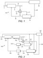
- Fig. 1 shows a first embodiment of a system 50 for compensating for signal error.
- the system can be used in a number of applications, for example in the processing or control system of an Inertial Measurement Unit ("IMU") and sensors thereof.
- IMU Inertial Measurement Unit
- One example is the combination of data from multiple sensors of the same type, e.g. two gyroscopes and/or two accelerometers, for example in a platform guidance system where the sensors may be used for stabilisation of the platform.
- a first signal 1 is received from a first sensor (not shown).
- the first signal 1 is indicative of a movement characteristic, such as angular rate, angular acceleration, linear rate or linear acceleration.
- a device 5 applies an error compensation to the first signal 1 to produce an output signal 10.
- the output signal 10 may then be transmitted onwards.
- the output signal 10 is also transmitted to a device 20 for measuring the difference between two signals.
- a second signal 15 is received from a second sensor (not shown).
- the second signal 15 is also indicative of said movement characteristic. That is, the first sensor and the second sensor measure the same movement characteristic, for example angular rate.
- the first sensor and the second sensor may be different types of sensors, or may have different characteristics.
- the output signal 10 may therefore be based on the better performance parameters of the different sensors using knowledge of their different error characteristics combined with a measure of the instantaneous movement characteristic.
- the first sensor may be selected as the "reference" sensor, for example due to having a lower high frequency noise than the second sensor.
- this type of sensor typically has a worse performance over long time periods, so the second sensor may be chosen that has a better performance over long time periods.
- the second signal 15 is received by the device 20, which outputs a signal 21 indicative of the difference between the output signal 10 and the second signal 15.
- the signal 21 from the device 20 is then transmitted to a device 22 for calculating an estimate of the error of the output signal 10.
- the first signal 1 is also transmitted to a device 25 for calculating a gain factor.
- the gain factor may be varied, for example in order to tune the response of the system, that is the output signal 10, for different operating conditions.
- the gain factor may be related to the first signal, for example the gain factor may be positively or negatively correlated with the first signal 1.
- the gain factor may be correlated with the magnitude of the first signal, such as a magnitude value of angular rate.
- the operating conditions may be related to the movement characteristic, or a derivative of the movement characteristic, for example angular rate or angular acceleration.
- the gain factor may be increased or decreased in response to this. This may reflect that the error from the first sensor may be likely to increase as the magnitude of the movement characteristic increases.
- the gain factor output from the device 25 may be in the range from 0 to 1.
- the gain factor may be set to zero for certain operating conditions, for example if the movement characteristic is above or below a predefined value. As discussed above, the gain factor may then be varied from 0 to 1 based on a predefined correlation with the operating conditions, for example a positive or negative correlation with the first signal 1, which is indicative of the movement characteristic.
- the gain factor may then be sent in a signal 26 output from the device 25, which is received by the device 22. It will be appreciated that the gain factor could be calculated by the device 22.
- the device 22 applies the gain factor to the signal 21, which is indicative of the difference between said output signal and said second signal, and outputs an error signal 30 indicative of an estimate of the error of the output signal 10.
- the error estimate which may be an instantaneous error estimate or a total error estimate, is then sent to the device 5 for applying the error compensation to the first signal.
- Fig. 2 shows a second embodiment of a system 500 for compensating for signal error.
- a first signal 101 is received from a first sensor (not shown).
- the first signal 101 is indicative of a movement characteristic, such as angular rate, angular acceleration, linear rate or linear acceleration.
- a number of devices 151, 152 apply an error compensation to the first signal 101 to produce an output signal 110.
- the error compensation comprises a bias compensation and a scale factor compensation.
- the bias compensation is applied by device 152, and the scale factor compensation is applied by device 151.
- the output signal 110 may then be transmitted onwards.
- the output signal 10 is also transmitted to a device 120 for measuring the difference between two signals.
- a second signal 115 is received from a second sensor (not shown).
- the second signal 115 is also indicative of said movement characteristic. That is, the first sensor and the second sensor measure the same movement characteristic, for example angular rate.
- the first sensor and the second sensor may be different types of sensors, or may have different characteristics.
- the output signal 110 may therefore be based on the better performance parameters of the different sensors.
- the first sensor may be selected as the "reference" sensor, for example due to having a lower high frequency noise than the second sensor.
- this type of sensor typically has a worse performance over long time periods, so the second sensor may be chosen that has a better performance over long time periods.
- the second signal 115 is received by the device 120, which outputs a signal 121 indicative of the difference between the output signal 110 and the second signal 115.
- the signal 121 from the device 120 is then transmitted to a number of devices 130, 135 for calculating an estimate of the error of the output signal 110.
- the errors are characterised as a bias error and a scale factor error.
- the different errors will have different influences on the output signal 110.
- Appropriate selection of parameters, for example gain allows the different error components to be configured for any particular operating condition, due to their different influence on the output signal 110 under different operating conditions.
- the scale factor error has maximum influence at high rotation rates, and the bias error having maximum influence at low rotation rates. As such, these are compensated individually as described in more detail below.
- output signal 110 first signal ⁇ 1 ⁇ scale factor error ⁇ bias error
- the signal 121 which is indicative of the difference between the output signal 110 and the second signal 115, is transmitted to a device 130 for calculating a bias error.
- the device 130 also receives the first signal 101 and calculates a bias gain factor using the first signal 101.
- the bias gain factor may, therefore, be representative of the magnitude of the movement characteristic, for example the magnitude of angular rate.
- the bias gain factor may be in the range from 0 to 1.
- the bias gain factor may be set to zero for certain operating conditions, for example if the movement characteristic is below a predefined value, such as below a given magnitude of angular rate.
- the bias gain factor may then be varied from 0 to 1 based on a predefined negative correlation with the first signal 101, which is indicative of the movement characteristic. That is, as the magnitude of the movement characteristic increases, the bias gain factor decreases.
- the device 130 applies the bias gain factor to the signal 121, which is indicative of the difference between said output signal and said second signal, and outputs a signal 131 indicative of an estimate of the instantaneous bias error of the output signal 110.
- the bias error signal 131 may be received by device 132 for accumulating or integrating the instantaneous bias error with preceding error values and outputting a signal 133 indicative of the total bias error.
- the bias error referred to above and in calculations [3] and [4] may be the instantaneous bias error or the total bias error.
- the signal 121 which is indicative of the difference between the output signal 110 and the second signal 115, is transmitted to a device 135 for calculating a scale factor error.
- a device 125 may be provided for calculating a first derivative of the movement characteristic.
- the device 125 may receive the first signal 101, which is indicative of the movement characteristic, and output a signal 126 indicative of the first derivative of the movement characteristic.
- the first derivative is angular acceleration.
- the device 135 receives the first signal 101 and signal 126, which is indicative of the first derivative of the movement characteristic, and calculates a scale factor gain factor using the first signal 101 and signal 126.
- the scale factor gain factor may, therefore, be representative of the magnitude of the movement characteristic, for example the magnitude of angular rate, and the magnitude of the first derivative of the movement characteristic, for example angular acceleration.
- the scale factor gain factor may be in the range from 0 to 1.
- the scale factor gain factor may be set to zero for certain operating conditions, for example if the movement characteristic, and/or its first derivative are above or below predefined values, such as below a given magnitude of angular rate or angular acceleration.
- the scale factor gain factor may then be varied from 0 to 1 based on a predefined positive correlation with the movement characteristic and the first derivative of the movement characteristic. That is, as the magnitude of the movement characteristic increases, and the magnitude of the first derivative of the movement characteristic increases, the scale factor gain factor increases.
- the device 135 applies the scale factor gain factor to the signal 121, which is indicative of the difference between said output signal and said second signal, and outputs a signal 136 indicative of an estimate of the instantaneous scale factor error of the output signal 110.
- the scale factor error signal 136 may be received by device 137 for accumulating or integrating the instantaneous scale factor error with preceding error values and outputting a signal 138 indicative of the total scale factor error.
- the scale factor error referred to above and in calculations [2] and [4] may be the instantaneous bias error or the total bias error.
- the scale factor error and bias error values are then transmitted to the respective devices 151, 152 for calculation of the scale factor compensation and bias compensation as discussed above.
- the gain factor(s) in the present disclosure may be chosen or calculated according to the characteristics of each sensor and the dynamic operating range of the system.
- the scale factor gain factor may be calculated to have a value at a maximum angular rate such that the time constant is less than 1 second.
- the scale factor gain factor may be set to zero for angular rates below 2 degrees/second.
- the bias gain factor may be set to provide a time constant of about 5 seconds at low angular rates, and may reduce as the angular rate increases to increase the time constant by a factor of four at the maximum angular rate.
Landscapes
- Engineering & Computer Science (AREA)
- Radar, Positioning & Navigation (AREA)
- Remote Sensing (AREA)
- Physics & Mathematics (AREA)
- General Physics & Mathematics (AREA)
- Automation & Control Theory (AREA)
- Manufacturing & Machinery (AREA)
- Gyroscopes (AREA)
- Navigation (AREA)
- Indication And Recording Devices For Special Purposes And Tariff Metering Devices (AREA)
Claims (13)
- Verfahren zum Kompensieren eines Signalfehlers, umfassend:Empfangen eines ersten Signals von einem ersten Sensor, wobei das erste Signal ein Bewegungsmerkmal angibt;Anwenden einer Fehlerkompensation auf das erste Signal, um ein Ausgabesignal zu erzeugen;Anwenden eines variablen Gain-Faktors auf die Fehlerkompensation;Empfangen eines zweiten Signals von einem zweiten Sensor, welcher ein Bewegungsmerkmal angibt;wobei die Fehlerkompensation mithilfe des Unterschieds zwischen dem Ausgabesignal und dem zweiten Signal berechnet wird, undwobei der variable Gain-Faktor mithilfe des ersten Signals berechnet wird,dadurch gekennzeichnet, dass der zweite Sensor eine bessere Vorspannung, einen besseren Scale-Faktor oder bessere langfristige Stabilität zeigt als der erste Sensor.
- Verfahren nach Anspruch 1, wobei das erste Signal und das zweite Signal jeweils von einem Gyroskop oder einem Beschleunigungsmesser stammen, und wobei das Bewegungsmerkmal die Winkelgeschwindigkeit, Winkelbeschleunigung, Lineargeschwindigkeit oder Linearbeschleunigung ist.
- Verfahren nach Anspruch 1 oder 2, wobei der erste Sensor eine unterschiedliche Art Sensor ist oder unterschiedliche Merkmale aufweist als der zweite Sensor.
- Verfahren nach einem der vorstehenden Ansprüche, wobei der Gain-Faktor als eine Funktion von einer oder mehreren Betriebsbedingungen entsprechend dem Bewegungsmerkmal variiert.
- Verfahren nach Anspruch 4, wobei die eine oder die mehreren Betriebsbedingungen vorbestimmt sind.
- Verfahren nach Anspruch 4 oder 5, wobei die eine oder die mehreren Betriebsbedingungen jeweils einen gegebenen Wert des Bewegungsmerkmals umfassen.
- Verfahren nach Anspruch 4, 5 oder 6, wobei die eine oder die mehreren Betriebsbedingungen jeweils einen gegebenen Wert einer ersten Ableitung des Bewegungsmerkmals umfassen.
- Verfahren nach einem der vorstehenden Ansprüche, wobei der Gain-Faktor zwischen 0-1 variiert.
- Verfahren nach einem der vorstehenden Ansprüche, wobei die Fehlerkompensation eine Vielzahl von Fehlerkompensationen umfasst.
- Verfahren nach Anspruch 9, ferner umfassend ein Anwenden unterschiedlicher Gain-Faktoren auf jede der Fehlerkompensationen.
- Verfahren nach Anspruch 9 oder 10, wobei eine erste der Vielzahl von Fehlerkompensationen auf Vorspannung bezogen ist, und eine zweite der Vielzahl von Fehlerkompensationen auf den Scale-Faktor bezogen ist.
- Verfahren nach Anspruch 10 oder 11, ferner umfassend ein Verringern eines Gain-Faktors, welcher auf eine erste der Vielzahl von Fehlerkompensationen angewendet wird, wenn sich die Stärke des Bewegungsmerkmals erhöht, und Erhöhen eines Gain-Faktors, welcher auf eine zweite der Vielzahl von Fehlerkompensationen angewendet wird, wenn sich die Stärke des Bewegungsmerkmals erhöht.
- System zum Kompensieren eines Signalfehlers, umfassend:einen ersten Sensor, welcher dazu konfiguriert ist, ein erstes Signal zu erzeugen, welches ein Bewegungsmerkmal angibt;einen zweiten Sensor, welcher dazu konfiguriert ist, ein zweites Signal zu erzeugen, welches das Bewegungsmerkmal angibt;eine oder mehrere Vorrichtungen, welche dazu konfiguriert sind, eine Fehlerkompensation auf das erste Signal anzuwenden, um ein Ausgabesignal zu erzeugen, und dazu, einen variablen Gain-Faktor auf die Fehlerkompensation anzuwenden;wobei die eine oder die mehreren Vorrichtungen die Fehlerkompensation mithilfe des Unterschieds zwischen dem Ausgabesignal und dem zweiten Signal berechnen, und den Gain-Faktor mithilfe des ersten Signals berechnen, dadurch gekennzeichnet, dass:
der zweite Sensor eine bessere Vorspannung, einen besseren Scale-Faktor oder bessere langfristige Stabilität zeigt als der erste Sensor.
Applications Claiming Priority (3)
| Application Number | Priority Date | Filing Date | Title |
|---|---|---|---|
| GB1501206.5A GB2534417B (en) | 2015-01-26 | 2015-01-26 | Multiple sensor integration |
| PCT/GB2016/050156 WO2016120600A1 (en) | 2015-01-26 | 2016-01-26 | Multiple sensor integration |
| EP16701875.3A EP3250888B1 (de) | 2015-01-26 | 2016-01-26 | Integration mehrerer sensoren |
Related Parent Applications (2)
| Application Number | Title | Priority Date | Filing Date |
|---|---|---|---|
| EP16701875.3A Division-Into EP3250888B1 (de) | 2015-01-26 | 2016-01-26 | Integration mehrerer sensoren |
| EP16701875.3A Division EP3250888B1 (de) | 2015-01-26 | 2016-01-26 | Integration mehrerer sensoren |
Publications (2)
| Publication Number | Publication Date |
|---|---|
| EP3517892A1 EP3517892A1 (de) | 2019-07-31 |
| EP3517892B1 true EP3517892B1 (de) | 2021-05-05 |
Family
ID=52673890
Family Applications (2)
| Application Number | Title | Priority Date | Filing Date |
|---|---|---|---|
| EP19160741.5A Active EP3517892B1 (de) | 2015-01-26 | 2016-01-26 | Integration mehrerer sensoren |
| EP16701875.3A Active EP3250888B1 (de) | 2015-01-26 | 2016-01-26 | Integration mehrerer sensoren |
Family Applications After (1)
| Application Number | Title | Priority Date | Filing Date |
|---|---|---|---|
| EP16701875.3A Active EP3250888B1 (de) | 2015-01-26 | 2016-01-26 | Integration mehrerer sensoren |
Country Status (5)
| Country | Link |
|---|---|
| US (1) | US10415977B2 (de) |
| EP (2) | EP3517892B1 (de) |
| BR (1) | BR112017015675A2 (de) |
| GB (1) | GB2534417B (de) |
| WO (1) | WO2016120600A1 (de) |
Families Citing this family (1)
| Publication number | Priority date | Publication date | Assignee | Title |
|---|---|---|---|---|
| US11797026B2 (en) | 2020-05-28 | 2023-10-24 | Seiko Epson Corporation | Posture estimation device, sensor module, measurement system, moving object, and posture estimation method |
Family Cites Families (8)
| Publication number | Priority date | Publication date | Assignee | Title |
|---|---|---|---|---|
| US4095271A (en) * | 1977-04-20 | 1978-06-13 | Sundstrand Data Control, Inc. | Aircraft pitch attitude signal generator |
| US5184304A (en) * | 1991-04-26 | 1993-02-02 | Litton Systems, Inc. | Fault-tolerant inertial navigation system |
| US7421343B2 (en) * | 2005-10-27 | 2008-09-02 | Honeywell International Inc. | Systems and methods for reducing vibration-induced errors in inertial sensors |
| US7912664B2 (en) * | 2008-09-11 | 2011-03-22 | Northrop Grumman Guidance And Electronics Company, Inc. | Self calibrating gyroscope system |
| US7840381B2 (en) * | 2008-10-03 | 2010-11-23 | Honeywell International Inc. | Method and apparatus for determining the operational state of a navigation system |
| US8576169B2 (en) * | 2008-10-20 | 2013-11-05 | Sensor Platforms, Inc. | System and method for determining an attitude of a device undergoing dynamic acceleration |
| US8743219B1 (en) * | 2010-07-13 | 2014-06-03 | Marvell International Ltd. | Image rotation correction and restoration using gyroscope and accelerometer |
| SE536059C2 (sv) * | 2010-07-29 | 2013-04-16 | C2Sat Comm Ab | Förfarande för att driftkompensera ett positionsmätningsorgan |
-
2015
- 2015-01-26 GB GB1501206.5A patent/GB2534417B/en active Active
-
2016
- 2016-01-26 EP EP19160741.5A patent/EP3517892B1/de active Active
- 2016-01-26 US US15/545,822 patent/US10415977B2/en active Active
- 2016-01-26 EP EP16701875.3A patent/EP3250888B1/de active Active
- 2016-01-26 WO PCT/GB2016/050156 patent/WO2016120600A1/en not_active Ceased
- 2016-01-26 BR BR112017015675A patent/BR112017015675A2/pt not_active Application Discontinuation
Also Published As
| Publication number | Publication date |
|---|---|
| BR112017015675A2 (pt) | 2018-03-13 |
| EP3250888A1 (de) | 2017-12-06 |
| WO2016120600A1 (en) | 2016-08-04 |
| US10415977B2 (en) | 2019-09-17 |
| GB2534417A (en) | 2016-07-27 |
| GB201501206D0 (en) | 2015-03-11 |
| EP3250888B1 (de) | 2020-03-11 |
| EP3517892A1 (de) | 2019-07-31 |
| GB2534417B (en) | 2019-06-12 |
| US20180017389A1 (en) | 2018-01-18 |
Similar Documents
| Publication | Publication Date | Title |
|---|---|---|
| US8019538B2 (en) | System and method for high accuracy relative navigation | |
| US10365131B2 (en) | Hybrid inertial measurement unit | |
| US20160363460A1 (en) | Orientation model for inertial devices | |
| WO2014022664A2 (en) | Method and apparatus for data fusion of a three axis magnetometer and three axis accelerometer | |
| US10025891B1 (en) | Method of reducing random drift in the combined signal of an array of inertial sensors | |
| CN113261207B (zh) | 自适应颤噪噪声消除 | |
| RU2564380C1 (ru) | Способ коррекции бесплатформенной инерциальной навигационной системы | |
| US9429426B2 (en) | Adaptive inertial measurement system and method | |
| US20180283912A1 (en) | Signal processing device, detection device, physical quantity measurement device, electronic apparatus, and vehicle | |
| EP2172744B1 (de) | System und Verfahren zur Autokalibrierung von Inertialsensoren | |
| EP3517892B1 (de) | Integration mehrerer sensoren | |
| KR101974522B1 (ko) | 관성항법장치의 고도 보정 방법 및 장치 | |
| JP2024043518A (ja) | Mems加速度計システム、およびアビオニクスシステム | |
| US10088319B2 (en) | Method for determining states of a system using an estimation filter | |
| EP3250886B1 (de) | Gyroskop-schleifenfilter | |
| CN111812985A (zh) | 一种基于双滤波器扰动观测器的惯性回路窄带大幅值扰动抑制方法 | |
| Shen et al. | Algorithms for correction of the navigation information using a satellite radio navigation system under anomalous measurement conditions | |
| CN118999628A (zh) | 一种校正mems陀螺仪温度漂移的方法、装置、计算设备及存储介质 | |
| US20250027969A1 (en) | Method for limiting baro-inertial speed correction and associated system | |
| CN117879538A (zh) | 一种抑制高频测量噪声的延迟补偿滤波方法及相关设备 | |
| KR102868566B1 (ko) | 복합 보정 항법 장치 및 동작 방법, 이를 포함하는 관성 항법 시스템 | |
| RU2635846C1 (ru) | Способ компенсации дрейфа нулевых сигналов гироскопических датчиков | |
| US20190393909A1 (en) | Analog circuit time constant compensation method for a digital transmitter using an analog output | |
| CN120232432B (zh) | 基于陀螺仪-码盘的转台方位姿态估计方法和装置 | |
| US20250020485A1 (en) | Updating blending coefficients in real-time for virtual output of an array of sensors |
Legal Events
| Date | Code | Title | Description |
|---|---|---|---|
| PUAI | Public reference made under article 153(3) epc to a published international application that has entered the european phase |
Free format text: ORIGINAL CODE: 0009012 |
|
| STAA | Information on the status of an ep patent application or granted ep patent |
Free format text: STATUS: THE APPLICATION HAS BEEN PUBLISHED |
|
| AC | Divisional application: reference to earlier application |
Ref document number: 3250888 Country of ref document: EP Kind code of ref document: P |
|
| AK | Designated contracting states |
Kind code of ref document: A1 Designated state(s): AL AT BE BG CH CY CZ DE DK EE ES FI FR GB GR HR HU IE IS IT LI LT LU LV MC MK MT NL NO PL PT RO RS SE SI SK SM TR |
|
| STAA | Information on the status of an ep patent application or granted ep patent |
Free format text: STATUS: REQUEST FOR EXAMINATION WAS MADE |
|
| 17P | Request for examination filed |
Effective date: 20191120 |
|
| RBV | Designated contracting states (corrected) |
Designated state(s): AL AT BE BG CH CY CZ DE DK EE ES FI FR GB GR HR HU IE IS IT LI LT LU LV MC MK MT NL NO PL PT RO RS SE SI SK SM TR |
|
| GRAP | Despatch of communication of intention to grant a patent |
Free format text: ORIGINAL CODE: EPIDOSNIGR1 |
|
| STAA | Information on the status of an ep patent application or granted ep patent |
Free format text: STATUS: GRANT OF PATENT IS INTENDED |
|
| INTG | Intention to grant announced |
Effective date: 20201210 |
|
| GRAS | Grant fee paid |
Free format text: ORIGINAL CODE: EPIDOSNIGR3 |
|
| GRAA | (expected) grant |
Free format text: ORIGINAL CODE: 0009210 |
|
| STAA | Information on the status of an ep patent application or granted ep patent |
Free format text: STATUS: THE PATENT HAS BEEN GRANTED |
|
| AC | Divisional application: reference to earlier application |
Ref document number: 3250888 Country of ref document: EP Kind code of ref document: P |
|
| AK | Designated contracting states |
Kind code of ref document: B1 Designated state(s): AL AT BE BG CH CY CZ DE DK EE ES FI FR GB GR HR HU IE IS IT LI LT LU LV MC MK MT NL NO PL PT RO RS SE SI SK SM TR |
|
| REG | Reference to a national code |
Ref country code: GB Ref legal event code: FG4D |
|
| REG | Reference to a national code |
Ref country code: CH Ref legal event code: EP |
|
| REG | Reference to a national code |
Ref country code: AT Ref legal event code: REF Ref document number: 1390348 Country of ref document: AT Kind code of ref document: T Effective date: 20210515 |
|
| REG | Reference to a national code |
Ref country code: DE Ref legal event code: R096 Ref document number: 602016057661 Country of ref document: DE |
|
| REG | Reference to a national code |
Ref country code: IE Ref legal event code: FG4D |
|
| REG | Reference to a national code |
Ref country code: LT Ref legal event code: MG9D |
|
| REG | Reference to a national code |
Ref country code: AT Ref legal event code: MK05 Ref document number: 1390348 Country of ref document: AT Kind code of ref document: T Effective date: 20210505 |
|
| PG25 | Lapsed in a contracting state [announced via postgrant information from national office to epo] |
Ref country code: AT Free format text: LAPSE BECAUSE OF FAILURE TO SUBMIT A TRANSLATION OF THE DESCRIPTION OR TO PAY THE FEE WITHIN THE PRESCRIBED TIME-LIMIT Effective date: 20210505 Ref country code: BG Free format text: LAPSE BECAUSE OF FAILURE TO SUBMIT A TRANSLATION OF THE DESCRIPTION OR TO PAY THE FEE WITHIN THE PRESCRIBED TIME-LIMIT Effective date: 20210805 Ref country code: HR Free format text: LAPSE BECAUSE OF FAILURE TO SUBMIT A TRANSLATION OF THE DESCRIPTION OR TO PAY THE FEE WITHIN THE PRESCRIBED TIME-LIMIT Effective date: 20210505 Ref country code: LT Free format text: LAPSE BECAUSE OF FAILURE TO SUBMIT A TRANSLATION OF THE DESCRIPTION OR TO PAY THE FEE WITHIN THE PRESCRIBED TIME-LIMIT Effective date: 20210505 Ref country code: FI Free format text: LAPSE BECAUSE OF FAILURE TO SUBMIT A TRANSLATION OF THE DESCRIPTION OR TO PAY THE FEE WITHIN THE PRESCRIBED TIME-LIMIT Effective date: 20210505 |
|
| PG25 | Lapsed in a contracting state [announced via postgrant information from national office to epo] |
Ref country code: IS Free format text: LAPSE BECAUSE OF FAILURE TO SUBMIT A TRANSLATION OF THE DESCRIPTION OR TO PAY THE FEE WITHIN THE PRESCRIBED TIME-LIMIT Effective date: 20210905 Ref country code: GR Free format text: LAPSE BECAUSE OF FAILURE TO SUBMIT A TRANSLATION OF THE DESCRIPTION OR TO PAY THE FEE WITHIN THE PRESCRIBED TIME-LIMIT Effective date: 20210806 Ref country code: SE Free format text: LAPSE BECAUSE OF FAILURE TO SUBMIT A TRANSLATION OF THE DESCRIPTION OR TO PAY THE FEE WITHIN THE PRESCRIBED TIME-LIMIT Effective date: 20210505 Ref country code: PT Free format text: LAPSE BECAUSE OF FAILURE TO SUBMIT A TRANSLATION OF THE DESCRIPTION OR TO PAY THE FEE WITHIN THE PRESCRIBED TIME-LIMIT Effective date: 20210906 Ref country code: RS Free format text: LAPSE BECAUSE OF FAILURE TO SUBMIT A TRANSLATION OF THE DESCRIPTION OR TO PAY THE FEE WITHIN THE PRESCRIBED TIME-LIMIT Effective date: 20210505 Ref country code: LV Free format text: LAPSE BECAUSE OF FAILURE TO SUBMIT A TRANSLATION OF THE DESCRIPTION OR TO PAY THE FEE WITHIN THE PRESCRIBED TIME-LIMIT Effective date: 20210505 Ref country code: PL Free format text: LAPSE BECAUSE OF FAILURE TO SUBMIT A TRANSLATION OF THE DESCRIPTION OR TO PAY THE FEE WITHIN THE PRESCRIBED TIME-LIMIT Effective date: 20210505 Ref country code: NO Free format text: LAPSE BECAUSE OF FAILURE TO SUBMIT A TRANSLATION OF THE DESCRIPTION OR TO PAY THE FEE WITHIN THE PRESCRIBED TIME-LIMIT Effective date: 20210805 |
|
| REG | Reference to a national code |
Ref country code: NL Ref legal event code: MP Effective date: 20210505 |
|
| PG25 | Lapsed in a contracting state [announced via postgrant information from national office to epo] |
Ref country code: NL Free format text: LAPSE BECAUSE OF FAILURE TO SUBMIT A TRANSLATION OF THE DESCRIPTION OR TO PAY THE FEE WITHIN THE PRESCRIBED TIME-LIMIT Effective date: 20210505 |
|
| PG25 | Lapsed in a contracting state [announced via postgrant information from national office to epo] |
Ref country code: SK Free format text: LAPSE BECAUSE OF FAILURE TO SUBMIT A TRANSLATION OF THE DESCRIPTION OR TO PAY THE FEE WITHIN THE PRESCRIBED TIME-LIMIT Effective date: 20210505 Ref country code: ES Free format text: LAPSE BECAUSE OF FAILURE TO SUBMIT A TRANSLATION OF THE DESCRIPTION OR TO PAY THE FEE WITHIN THE PRESCRIBED TIME-LIMIT Effective date: 20210505 Ref country code: EE Free format text: LAPSE BECAUSE OF FAILURE TO SUBMIT A TRANSLATION OF THE DESCRIPTION OR TO PAY THE FEE WITHIN THE PRESCRIBED TIME-LIMIT Effective date: 20210505 Ref country code: RO Free format text: LAPSE BECAUSE OF FAILURE TO SUBMIT A TRANSLATION OF THE DESCRIPTION OR TO PAY THE FEE WITHIN THE PRESCRIBED TIME-LIMIT Effective date: 20210505 Ref country code: SM Free format text: LAPSE BECAUSE OF FAILURE TO SUBMIT A TRANSLATION OF THE DESCRIPTION OR TO PAY THE FEE WITHIN THE PRESCRIBED TIME-LIMIT Effective date: 20210505 Ref country code: DK Free format text: LAPSE BECAUSE OF FAILURE TO SUBMIT A TRANSLATION OF THE DESCRIPTION OR TO PAY THE FEE WITHIN THE PRESCRIBED TIME-LIMIT Effective date: 20210505 Ref country code: CZ Free format text: LAPSE BECAUSE OF FAILURE TO SUBMIT A TRANSLATION OF THE DESCRIPTION OR TO PAY THE FEE WITHIN THE PRESCRIBED TIME-LIMIT Effective date: 20210505 |
|
| REG | Reference to a national code |
Ref country code: DE Ref legal event code: R097 Ref document number: 602016057661 Country of ref document: DE |
|
| PLBE | No opposition filed within time limit |
Free format text: ORIGINAL CODE: 0009261 |
|
| STAA | Information on the status of an ep patent application or granted ep patent |
Free format text: STATUS: NO OPPOSITION FILED WITHIN TIME LIMIT |
|
| 26N | No opposition filed |
Effective date: 20220208 |
|
| PG25 | Lapsed in a contracting state [announced via postgrant information from national office to epo] |
Ref country code: IS Free format text: LAPSE BECAUSE OF FAILURE TO SUBMIT A TRANSLATION OF THE DESCRIPTION OR TO PAY THE FEE WITHIN THE PRESCRIBED TIME-LIMIT Effective date: 20210905 Ref country code: AL Free format text: LAPSE BECAUSE OF FAILURE TO SUBMIT A TRANSLATION OF THE DESCRIPTION OR TO PAY THE FEE WITHIN THE PRESCRIBED TIME-LIMIT Effective date: 20210505 |
|
| PG25 | Lapsed in a contracting state [announced via postgrant information from national office to epo] |
Ref country code: IT Free format text: LAPSE BECAUSE OF FAILURE TO SUBMIT A TRANSLATION OF THE DESCRIPTION OR TO PAY THE FEE WITHIN THE PRESCRIBED TIME-LIMIT Effective date: 20210505 |
|
| PG25 | Lapsed in a contracting state [announced via postgrant information from national office to epo] |
Ref country code: MC Free format text: LAPSE BECAUSE OF FAILURE TO SUBMIT A TRANSLATION OF THE DESCRIPTION OR TO PAY THE FEE WITHIN THE PRESCRIBED TIME-LIMIT Effective date: 20210505 |
|
| REG | Reference to a national code |
Ref country code: CH Ref legal event code: PL |
|
| REG | Reference to a national code |
Ref country code: BE Ref legal event code: MM Effective date: 20220131 |
|
| PG25 | Lapsed in a contracting state [announced via postgrant information from national office to epo] |
Ref country code: LU Free format text: LAPSE BECAUSE OF NON-PAYMENT OF DUE FEES Effective date: 20220126 |
|
| PG25 | Lapsed in a contracting state [announced via postgrant information from national office to epo] |
Ref country code: BE Free format text: LAPSE BECAUSE OF NON-PAYMENT OF DUE FEES Effective date: 20220131 |
|
| PG25 | Lapsed in a contracting state [announced via postgrant information from national office to epo] |
Ref country code: LI Free format text: LAPSE BECAUSE OF NON-PAYMENT OF DUE FEES Effective date: 20220131 Ref country code: CH Free format text: LAPSE BECAUSE OF NON-PAYMENT OF DUE FEES Effective date: 20220131 |
|
| PG25 | Lapsed in a contracting state [announced via postgrant information from national office to epo] |
Ref country code: IE Free format text: LAPSE BECAUSE OF NON-PAYMENT OF DUE FEES Effective date: 20220126 |
|
| P01 | Opt-out of the competence of the unified patent court (upc) registered |
Effective date: 20230630 |
|
| PG25 | Lapsed in a contracting state [announced via postgrant information from national office to epo] |
Ref country code: MK Free format text: LAPSE BECAUSE OF FAILURE TO SUBMIT A TRANSLATION OF THE DESCRIPTION OR TO PAY THE FEE WITHIN THE PRESCRIBED TIME-LIMIT Effective date: 20210505 Ref country code: CY Free format text: LAPSE BECAUSE OF FAILURE TO SUBMIT A TRANSLATION OF THE DESCRIPTION OR TO PAY THE FEE WITHIN THE PRESCRIBED TIME-LIMIT Effective date: 20210505 |
|
| PG25 | Lapsed in a contracting state [announced via postgrant information from national office to epo] |
Ref country code: HU Free format text: LAPSE BECAUSE OF FAILURE TO SUBMIT A TRANSLATION OF THE DESCRIPTION OR TO PAY THE FEE WITHIN THE PRESCRIBED TIME-LIMIT; INVALID AB INITIO Effective date: 20160126 |
|
| PG25 | Lapsed in a contracting state [announced via postgrant information from national office to epo] |
Ref country code: TR Free format text: LAPSE BECAUSE OF FAILURE TO SUBMIT A TRANSLATION OF THE DESCRIPTION OR TO PAY THE FEE WITHIN THE PRESCRIBED TIME-LIMIT Effective date: 20210505 |
|
| PG25 | Lapsed in a contracting state [announced via postgrant information from national office to epo] |
Ref country code: MT Free format text: LAPSE BECAUSE OF FAILURE TO SUBMIT A TRANSLATION OF THE DESCRIPTION OR TO PAY THE FEE WITHIN THE PRESCRIBED TIME-LIMIT Effective date: 20210505 |
|
| PGFP | Annual fee paid to national office [announced via postgrant information from national office to epo] |
Ref country code: GB Payment date: 20251220 Year of fee payment: 11 |
|
| PGFP | Annual fee paid to national office [announced via postgrant information from national office to epo] |
Ref country code: FR Payment date: 20251217 Year of fee payment: 11 |
|
| PGFP | Annual fee paid to national office [announced via postgrant information from national office to epo] |
Ref country code: DE Payment date: 20251217 Year of fee payment: 11 |