EP3517880B1 - Ejektorgestell - Google Patents
Ejektorgestell Download PDFInfo
- Publication number
- EP3517880B1 EP3517880B1 EP19153971.7A EP19153971A EP3517880B1 EP 3517880 B1 EP3517880 B1 EP 3517880B1 EP 19153971 A EP19153971 A EP 19153971A EP 3517880 B1 EP3517880 B1 EP 3517880B1
- Authority
- EP
- European Patent Office
- Prior art keywords
- plunger
- casing
- conduit
- fluid
- respect
- Prior art date
- Legal status (The legal status is an assumption and is not a legal conclusion. Google has not performed a legal analysis and makes no representation as to the accuracy of the status listed.)
- Active
Links
Images






Classifications
-
- B—PERFORMING OPERATIONS; TRANSPORTING
- B64—AIRCRAFT; AVIATION; COSMONAUTICS
- B64D—EQUIPMENT FOR FITTING IN OR TO AIRCRAFT; FLIGHT SUITS; PARACHUTES; ARRANGEMENT OR MOUNTING OF POWER PLANTS OR PROPULSION TRANSMISSIONS IN AIRCRAFT
- B64D1/00—Dropping, ejecting, releasing or receiving articles, liquids, or the like, in flight
- B64D1/02—Dropping, ejecting, or releasing articles
- B64D1/04—Dropping, ejecting, or releasing articles the articles being explosive, e.g. bombs
- B64D1/06—Bomb releasing; Bomb doors
-
- B—PERFORMING OPERATIONS; TRANSPORTING
- B64—AIRCRAFT; AVIATION; COSMONAUTICS
- B64D—EQUIPMENT FOR FITTING IN OR TO AIRCRAFT; FLIGHT SUITS; PARACHUTES; ARRANGEMENT OR MOUNTING OF POWER PLANTS OR PROPULSION TRANSMISSIONS IN AIRCRAFT
- B64D1/00—Dropping, ejecting, releasing or receiving articles, liquids, or the like, in flight
- B64D1/02—Dropping, ejecting, or releasing articles
- B64D1/04—Dropping, ejecting, or releasing articles the articles being explosive, e.g. bombs
-
- B—PERFORMING OPERATIONS; TRANSPORTING
- B64—AIRCRAFT; AVIATION; COSMONAUTICS
- B64D—EQUIPMENT FOR FITTING IN OR TO AIRCRAFT; FLIGHT SUITS; PARACHUTES; ARRANGEMENT OR MOUNTING OF POWER PLANTS OR PROPULSION TRANSMISSIONS IN AIRCRAFT
- B64D37/00—Arrangements in connection with fuel supply for power plant
- B64D37/02—Tanks
- B64D37/06—Constructional adaptations thereof
- B64D37/12—Constructional adaptations thereof jettisonable
-
- F—MECHANICAL ENGINEERING; LIGHTING; HEATING; WEAPONS; BLASTING
- F41—WEAPONS
- F41F—APPARATUS FOR LAUNCHING PROJECTILES OR MISSILES FROM BARRELS, e.g. CANNONS; LAUNCHERS FOR ROCKETS OR TORPEDOES; HARPOON GUNS
- F41F5/00—Launching-apparatus for gravity-propelled missiles or projectiles
Definitions
- the presently disclosed subject matter relates to devices for carrying and releasing stores from a vehicle, in particular to ejector racks for carrying and releasing a store with respect to an air vehicle.
- the presently disclosed subject matter in particular relates to ejector racks that are actuated using pressurized gas.
- Stores such as for example bombs and missiles, are commonly carried by air vehicles, with a requirement to enable the stores to be released when required by the pilot or other aircrew.
- carrying and release functions are provided by devices for carrying and releasing stores, typically in the form of ejector racks, in which actuation thereof to release the stores is by ignition of gas cartridges to provide a pressurized gas.
- GB 2,414,782 discloses an ejector release system for an aircraft-mounted store, which comprises a reservoir for containing a precharged gaseous ejection medium, an actuation cylinder connected to the reservoir for effecting ejection of the store and a control valve between the reservoir and actuation cylinder, in which a snap-action pressure relief valve is mounted between the control valve and cylinder to allow excess pressure in the system downstream of the reservoir to be vented or diverted when the pressure exceeds a predetermined threshold pressure.
- the pressure relief valve may include a piston which is stepped to define an annular shoulder between larger and smaller diameter parts the shoulder constituting a marginal surface area which causes the piston to be urged towards the forwards position under gas input pressure, a vent passage which is out of registration with the inlet and outlet passages at the rearwards position of the piston but is in registration in the forwards position being provided in the piston.
- One or more resiliently-loaded balls urged into engagement with a corresponding detent formed in the piston in the rearwards or pressure-retaining position provide the snap action.
- US 4,050,656 discloses an ejector rack that is attachable to an aircraft and is for supporting and selectively releasing and/or ejecting a store that is carried internal of the aircraft, i.e., in a bomb bay.
- the store can be released from the ejector rack, and from the aircraft, in either of two ways, namely: by pushing on a manually operated release handle; or, by forced ejection, the only way used during flight of the aircraft. Forced ejection is achieved by sending an electrical impulse to either or both of two cartridges in the breech of the ejector rack, igniting the cartridge(s).
- Gas is generated thereby; and, the resultant pressure that is built up in a gas system in the rack provides force that acts upon an unlocking piston, causing the piston to move out of its "locked" position.
- the moving piston provides a force on a slide, rotating a latch that allows the main linkage bellcrank to rotate and thus to open two hooks which are holding the store, thereby releasing the suspended store.
- gas pressure is manifolded to two sway brace ejection piston cylinders, and the ejection pistons therein are forcefully extended, causing positive and forcible ejection of the store by the ejection pistons.
- US 8,584,568 B1 discloses a bomb rack lock, as part of a bomb rack, comprising a plunger movable to engage a bomb rack linkage to be alternately secured and released and a solenoid body coupled to and operable to support the plunger.
- the plunger and the solenoid body are movable relative to each other and the bomb rack linkage and the solenoid body is movable between a first position and a second position.
- the bomb rack lock also includes a sensor to determine whether the solenoid body is in the first position.
- the plunger is movable to engage and disengage the bomb rack linkage with the solenoid body in the first position. In the second position, the solenoid body prevents engagement between the plunger and the bomb rack linkage.
- the invention provides a support and release device for releasably supporting a store as defined in claim 1.
- the invention also provides an air vehicle comprising at least one such support and release device which is defined in claim 12 and a method for releasably supporting a store which is defined in claim 13. Preferred embodiments are defined in the dependent claims.
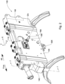
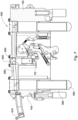
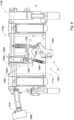
- a support and release device (also referred to interchangeably herein as a suspension and release device, and/or also referred to interchangeably herein as a carrying and release device) according to a first example of the presently disclosed subject matter, generally designated 100, comprises a lug engagement release system 300, actuation system 600, and safety system 700 comprising safety lock 799.
- the lug engagement release system 300 is operatively coupled to actuator system 600.
- the safety lock 799 is configured for selectively, and alternately, coupling and decoupling with respect to at least the lug engagement release system 300 to provide a coupled mode and a decoupled mode, respectively.
- lug engagement release system 300 is configured for:
- the actuator system 600 is configured for being actuated based on an actuation pressure AP being applied thereto, and safety system 700 is configured for preventing said actuation pressure AP being applied to the actuator system 600 when the safety lock 799 is in coupled mode.
- the support and release device 100 finds particular application in the form of an ejector rack (and is thus interchangeably referred to herein as an ejector rack, or as a stores ejector rack, or as a rack), for carrying a store, on or in an air vehicle, and in particular for releasably supporting such a store.
- the support and release device 100 is configured for carrying the store in suspended configuration, and for selectively releasing the store from the air vehicle.
- such a store can be a bomb, missile, rocket, external fuel tank, and so on, and an example thereof is illustrated in Fig. 1 and designated with the reference numeral 10.
- the store 10 is in any case characterized in being equipped with at least one lug 15 ( Fig. 4 ), by which the store 10 is releasably engaged to and suspended from, i.e., with respect to, the device 100.
- the store 10 has a single lug 15, and thus the device 100 only requires a single lug engagement release system 300, as will become clearer herein.
- the store may instead have several lugs, and the support and release device can correspondingly comprise a similar number of lug engagement release system 300, for example.
- engagement release mechanism 300 which is per se novel, is disclosed below.
- the device 100 comprises a housing 110, including two parallel laterally spaced side plates (also referred to interchangeably herein as side walls or side panels) 120, 130, integrally connected at the forward longitudinal ends thereof to forward end block 140 and aft end block 150, respectively to form a box-like structure.
- the two parallel laterally spaced side plates 120, 130 are otherwise non-integrally connected at the forward longitudinal ends thereof to forward end block 140 and aft end block 150, respectively, for example via welding, screws or other fasteners, to form the box-like structure.
- a bottom plate (not shown) can optionally be provided between the lower edges of the two side plates 120, 130, having an opening in registry with hook element 320, to enable a lug 15 of the store (not shown in Figs. 2 and 3 ) to be inserted from outside the device 100 into the space Q between the side plates 120, 130 and engage vertically with hook element 320.
- lug engagement release system 300 comprises hook element 320 pivotably mounted with respect to side plates 120, 130 at about lateral pivot axis 355, via pin 357, to allow pivoting of the hook element 320 about lateral pivot axis 355.
- the lateral pivot axis 355 is fixed with respect to the housing 110.
- Hook element 320 comprises a C-shaped or U-shaped engagement portion 322, defined by lower arm 321, base 323 and upper arm 325, which together partially circumscribe a space 326.
- the lower arm 321 is generally parallel to the upper arm 325, and facing in a general aft direction, and pivot axis 355 is located proximal to the connection between the upper arm 325 and the base 323.
- the hook element 320 further comprises an arm extension 330 that projects generally aft from upper arm 325, i.e., in a direction opposed to that of the lower arm 321 or upper arm 325.
- the extension 330 is pivotably connected at the end thereof to a first end 351 of a first link 350 via pin 353.
- the upper arm 325 of hook element 320 extends in a forward direction such as to enable contact between the lug and the arm in the "open" configuration shown in Fig. 6(b) , when the lug engagement release system 300 is in the disengaged configuration.
- the lug engagement release system 300 further comprises a coupling plate 360, pivotably mounted with respect to side plates 120, 130 about pivot axis 365 via a pin, to allow pivoting thereof about lateral pivot axis 365, which is fixed with respect to the housing 110.
- the coupling plate 360 comprises a first arm 361 radially projecting outwardly with respect to pivot axis 365, and a second arm 362 also radially projecting outwardly with respect to pivot axis 365 but angularly displaced from the first arm by an angle ⁇ .
- angle ⁇ is in the range of 20° and 160°, and more specifically about 90°.
- the free end 366 of the first arm 361 is pivotably connected to the second end 352 of first link 350 via pin 356.
- the free end 336 of second arm 362 is pivotably connected to a first stressed link 340 at its free end 346 via pin 349.
- the first stressed link 340 is pivotably mounted between side plates 120, 130 about lateral pivot axis 345 via a pin, to allow pivoting thereof about lateral pivot axis 345, which is fixed with respect to the housing 110.
- the free end 346 of the link 340 is reciprocably displaceable in a radial direction with respect to pivot axis 345.
- First stressed link 340 is pre-stressed, comprising a pre-stressed helical spring 348 that biases the free send 346 in a direction towards pivot axis 345.
- helical spring 348 can be replaced with a two or more than two spring elements, in each case each spring element being for example a helical spring or any other suitable spring capable of storing elastic potential energy when compressed.
- the lug engagement release system 300 further comprises an anvil element 380, pivotably mounted with respect to side plates 120, 130, coaxially with respect to coupling plate 360, to also allow pivoting of the anvil element 380 about said lateral pivot axis 365, which, as already mentioned, is fixed with respect to the housing 110.
- the anvil element 380 comprises a first arm 382 radially projecting outwardly with respect to pivot axis 365, and a second arm 384 also radially projecting outwardly with respect to pivot axis 365 but angularly displaced from the first arm 382 by an angle ⁇ .
- angle ⁇ is in the range of 200° and 160°, and more specifically about 180°.
- the anvil element 380 can be pivoted about said lateral pivot axis 365 with respect to coupling plate 360 about a limited angular displacement; thereafter, additional angular displacement of the anvil element 380 about said lateral pivot axis 365 causes the coupling plate 360 to concurrently be displaced with the anvil element 380.
- the anvil element 380 comprises a cam surface 383.
- a roller (not shown) connected to a microswitch (not shown) follows the cam surface 383, and thereby enables the microswitch to provide suitable control signals to a controller (not shown) indicative of whether the lug engagement release system 300 (via the angular position of the anvil element 380) is in the engaged configuration or the disengaged configuration.
- the free end 386 of the first arm 382 of the anvil element 360 projects in a general forward direction.
- the second arm 384 of the anvil element 380 projects in a general aft direction, and is freely pivoted at end 388 to one end 392 of second link 390 at pin 391.
- a pivoting member 370 is pivotably mounted with respect to side plates 120, 130 to allow pivoting thereof about lateral pivot axis 395, which is fixed with respect to the housing 110.
- the pivoting member 370 has a first arm 371 and a second arm 374 projecting away from lateral pivot axis 395 in generally opposite directions.
- a mechanical stop 377 is provided in the housing 110 in proximity to the pivoting member 370, limiting clockwise pivoting of the pivoting member 370 to an angular position when the second arm 374 abuts the mechanical stop 377 (as seen in Fig. 6(a) ), and limiting counter clockwise pivoting of the pivoting member 370 to an angular position when the first arm 371 abuts the mechanical stop 377 (as seen in Fig. 6(b) ).
- second link 390 is freely pivoted to second arm 374 via a pin
- first arm 371 is freely pivoted to a free end 242 of a second stressed link 240 at its free end 346 via a pin.
- Second stressed link 240 is pivotably mounted with respect to side plates 120, 130 to allow pivoting of the second stressed link 240 about lateral pivot axis 245, which is fixed with respect to the housing 110.
- the free end 242 of the second stressed link 240 is reciprocably displaceable in a radial direction with respect to pivot axis 245.
- Second stressed link 240 is pre-stressed, comprising a pre-stressed helical spring 248 that biases the free end 246 in a direction towards pivot axis 245.
- the free end 386 of first arm 382 of the anvil element 360 includes a roller 387, and is selectively actuable by the actuation system 600 to cause the lug engagement release system 300 to be actuated from the engaged configuration to the disengaged configuration, but only when the safety lock 799 of the safety system 700 is in the decoupled mode.
- a first kinematic chain A is provided by the first stressed link 340, the coupling plate 360, the first link 350 and the hook element 320.
- the first kinematic chain A has two stable relative positions that minimize the potential energy of the spring 348, and in which the pin 349 is at a maximum distance from an imaginary line L1 joining the pivot axis 345 and the pivot axis 365.
- the first stable position is illustrated in Fig. 6(a) , in which the pin 349 is above line L1, and in which the hook element 320 is rotated clockwise to the closed or engaged position, enabling engagement with a lug.
- the second stable position is illustrated in Fig. 6(b) , in which the pin 349 is below line L1, and in which the hook element 320 is rotated counter clockwise to the open or disengaged position, enabling release of a lug previously engaged thereto, or enabling a lug 15 to be inserted into space 326 for subsequent engagement via the lug engagement release system 300.
- the first kinematic chain A essentially thus operates as a lug engagement and release mechanism.
- the first kinematic chain A In order to load and engage a store 10, the first kinematic chain A must be in the second stable position shown in Fig. 6(b) , allowing the lug 15 to be vertically inserted into the bottom of housing 110 along vertical axis LA ( Fig. 4 ). As the lug is thus inserted and pushes against the upper arm 325, hook element 320 is caused to rotate in a clockwise direction about pivot axis 355 to the first stable position shown in Fig. 6(a) , causing the lower arm 321 to enter into the lug 15 and come into load supporting contact therewith, the lug being accommodated in space 326.
- a second kinematic chain B defined by anvil member 380, second link 390, pivoting member 370, and second stressed link 240.
- the second kinematic chain B operates as a geometrical locking and unlocking mechanism for the first kinematic chain A .
- the second kinematic chain B has two stable relative positions that minimize the potential energy of the spring 348, and in which the free end 242 is at a maximum distance from an imaginary line L2 joining the pivot axis 245 and the pivot axis 395.
- the first stable position is illustrated in Fig. 6(a) , in which the free end 242 is on the forward (left) side of line L2, and in which the pivoting member 370 is rotated clockwise to the geometrical locked position, thereby geometrically locking the first kinematic chain A.
- the second stable position is illustrated in Fig. 6(b) , in which the pin 349 is on the aft (right) side of line L2, and in which the pivoting member 370 is rotated counter clockwise to the unlocked position, thereby unlocking the first kinematic chain A, which can then go from the engaged configuration to the disengaged configuration.
- the actuation system 600 is configured, in operation of the support and release device 100, for operating under the action of gas pressure, and comprises an inlet port 610 connectable to a pressurized gas source 690.
- the gas source 690 can comprise one or more pressurized gas bottles filled with a suitable gas at high pressure, for example nitrogen gas.
- the gas source can include a pyrotechnic device that generates high pressure on ignition of pyrotechnic materials therein.
- actuation system 600 comprises piston 650 reciprocally mounted in cylinder 620 between a nominal first position P1 and a second positon P2.
- the actuation system 600 also comprises a conduit 680 extending between the inlet port 610 and the cylinder 620, providing fluid communication therebetween and thus providing fluid communication between the pressurized fluid source 690 (when connected to the inlet port 610 ) and the piston 650.
- the cylinder 620 can thus be considered as an extension of the fluid conduit 680, and piston 650 is thus reciprocally mounted with respect to the conduit 680.
- the actuator system 600 is configured for selectively providing an actuation operation such as to cause the lug engagement release system 300 to go from engaged configuration to the disengaged configuration (concurrent with the safety lock 799 being in uncoupled mode).
- This actuation operation is responsive to the aforementioned actuation pressure AP being applied within the actuator system 600 via gas provided by the pressurized gas source 690.
- the support and release device 100 is optionally configured for forcibly ejecting the store 10 away from the device 100, and thus away from the air vehicle, when disengaged therefrom.
- the support and release device 100 comprises an ejector system 500.
- the device 100 can be operated absent the ejector system 500, and thus allows the stores to drop away therefrom under the influence of gravity once released from the hook element.
- the support and release device 100 is configured for forcibly ejecting the store away from the device 100 and thus away from the air vehicle.
- the device 100 can be operated together with ejector system 500, configured for forcibly ejecting the store away from the device 100 and thus away from the air vehicle, once the stores 10 is released from the device 100.
- the ejector system 500 in at least this example comprises at least one ejection module 560 configured for forcibly ejecting a store away from the device 100.
- each ejection module 560 is configured for providing an ejection force generated under action of gas pressure provided by the actuation system 600.
- the ejector system 500 comprises two ejection modules 560, which are essentially identical to one another, and thus, only one shall be described herein.
- the ejector system 500 can instead comprise one or more than two ejection modules 560.
- one ejection module 560 is accommodated in the forward end block 140 and the other ejection module 560 is accommodated in aft end block 150.
- the ejection module 560 comprises a tubular housing 562, extending along a longitudinal axis 501.
- the tubular housing 562 accommodates a telescopic plunger element 564, which in alternative variations of this example can optionally include a plurality nested telescopic elements.
- the telescopic plunger element 564 comprises an end wall at a first longitudinal end 561 thereof having a small opening 569, and is closed at a second longitudinal end 563 thereof
- the second longitudinal end 563 comprises a padded abutment element 566, configured for abutting against the stores 10 when this is engaged with the device 100.
- the support and release device 100 further comprises sway braces 570, fixed to the forward end block 140 and to the aft end block 150.
- the first longitudinal end 561 is in open fluid communication with the conduit 680 via opening 569, and thus with the pressurized gas source 690 when this is connected to the inlet 610.
- the actuator system 600 is operated to apply the actuation pressure to the piston 650 via the conduit 680, pressure is also applied to the plunger element 564, which then extend out of their respective housings 562, thereby pushing off the stores 10 away from the device 100.
- safety lock 799 is, in at least this example, in the form of a pin that is reversible insertable into the housing 110 along extraction axis EA via aligned lateral openings 119 in the side plates 120, 130.
- the safety lock 799 is selectively inserted in the housing 110 along extraction axis EA to provide the coupled mode, and the safety lock 799 selectively extracted from the housing 110 along extraction axis EA to provide the decoupled mode.
- an arm 389 is rigidly affixed to the anvil element 380 radially projecting away from axis 365 in a general direction towards the extraction axis EA.
- the arm 389 abuts the safety lock 799, and thus the arm 389, together with the anvil element 380, are prevented from pivoting about pivot axis 365, thereby preventing the lug engagement release system 300 from going to the disengaged configuration, even if the actuator system 600 is operated to provide the actuation pressure AP.
- the arm 389 together with the anvil element 380 are now able to pivot about pivot axis 365, thereby allowing the lug engagement release system 300 to go to the disengaged configuration, responsive to the actuator system 600 being operated to provide the actuation pressure AP.
- the safety system 700 is configured for preventing said actuation pressure AP being applied to the actuator system 600, in particular to the piston 650, when the safety lock 799 is concurrently in coupled mode.
- the piston 650 In the engaged configuration, the piston 650 is in the nominal first position P1 ( Fig. 4 ).
- gas pressure at actuation pressure AP is applied to the piston 650, causing the piston 650 to be displaced to position P2 ( Fig. 7 ).
- the piston 650 which abuts the roller 387 at the first arm 382, applies a torque to the anvil member 380, initially pivoting the anvil in a counter clockwise direction (as seen in Fig. 6(a) ) about pivot axis 365 through a first angular displacement. Thereafter, and referring to Fig.
- the anvil member 380 locks onto the coupling plate 360, and together pivot by a further angular displacement about axis 365 until the geometric lock between the second link 390 and pivoting member 370 is unlocked, thereby pivoting the first stressed link 340 past the line L1, which then results on the first stressed link 340 to continue to pivot to its second position, concurrently causing the hook element 320 to pivot about axis 355 and thus to open, thereby disengaging the lug 15 and thus allowing the lug 15, and thus the stores 10, to be released.
- the safety system 700 is configured for providing free fluid communication between the inlet port 610 (and thus between the pressurized gas source 690 ) and the external environment E (typically the atmosphere) when the removable safety lock 799 is in said coupled mode.
- the safety system 700 is further configured for preventing free fluid communication between the inlet port 610 and the external environment E when the removable safety lock 799 is in the coupled mode.
- the piston 650 comprises a piston head 658 having an upper face in fluid communication with the conduit 680, and a lower projection 659 configured for abutment with respect to the anvil member 380, in particular the roller 387 thereof.
- the piston head 658 further comprises a peripheral wall 655 facing an inside of the cylinder 620.
- the piston head 658 further comprises a peripheral groove 657 on peripheral wall 655 in which a suitable ring seal 656 is accommodated for providing a suitable seal between the piston head 658 and the cylinder 620.
- safety system 700 is in the form of a fluid venting arrangement, and comprises a fluid venting conduit 710 provided in the piston 650.
- the fluid venting conduit 710 comprises an inlet opening 712 provided at the top face 652 of the piston 650, and two outlet openings 714, 716 provided on the peripheral wall 655.
- fluid venting conduit 710 there is also open fluid communication in fluid venting conduit 710 between inlet opening 712 and the two outlet openings 714, 716.
- safety system 700 further comprises two cylinder openings 112, 114, provided in the cylinder 620, passing through the thickness of the cylinder 620.
- the cylinder openings 112, 114 are located on the cylinder 620 at positions:
- the safety system 700 is designed to cope with a design condition in which the pressure within the conduit 680 begins to increase, for example as a result of the actuation system 600 being actuated (either by accident or because of a malfunction, for example).
- the safety system 700 provides an escape for the gas pressure, by venting the pressurized gas, which otherwise (i.e., under alternative conditions in which the safety system 700 is absent or non-operational) would increase, for example to the actuation pressure AP or greater.
- the safety system 700 thus prevents the pressure in the conduit 680 from reaching the actuation pressure AP and in particular from significantly exceeding the increasing actuation pressure AP, and thus enables the housing 110 to be designed with a considerably reduced safety margin, as regards capability for holding large internal pressure, as could otherwise be required under such alternative conditions.
- the safety lock 799 is uncoupled from the coupled mode to the uncoupled mode prior to take off, for example by ground crew.
- the actuation system 600 is actuated, the pressure within the conduit 680 increases up to the actuation pressure AP.
- the piston 650 moves from position P1 to position P3 under the action of the gas pressure, some gas is vented to the external environment E via the safety system 700, i.e., via the outlet openings 714, 716 which are, in position P3, temporarily in registry with cylinder openings 112, 114 and thus open with respect to the external environment E.
- the actuation pressure AP is sufficient, in the uncoupled mode, to further displace the piston 650 past position P3 so that the outlet openings 714, 716, are no longer in registry with the cylinder openings 112, 114, i.e., the outlet openings 714, 716, are effectively closed with respect to the external environment E, and thereby further venting of the pressurized gas to the external environment E from the conduit 680 is halted, preventing any further venting of gas from the actuator system 600 via the safety system 700.
- This also enables the full actuation pressure AP to be applied to the piston 650 which can then be fully displaced, first to position P4 ( Fig.
- the anvil member 380 locks onto the coupling plate 360, and together pivot by a further angular displacement about axis 365 until the geometric lock between the second link 390 and pivoting member 370 is unlocked, responsive to further displacement of the piston 650 from position P4 to position P2.
- the actuation system 600 also actuates the ejector system 500 causing the telescopic plunger elements 564 to be extended from the respective tubular housings 562 under action of gas pressure provided by the actuation system 600, thereby providing an ejection force to the stores 10 after this has been disengaged from the device 100.
- the pressure within the conduit 680 causes the piston 650 to be displaced from position P1 to position P3, and the piston 650 remains at position P3 since further displacement of the piston 650 is resisted by the anvil element 380, which is prevented from pivoting by abutment of the arm 389 against the coupled safety lock 799.
- the fluid venting conduit 710 allows venting of the pressurized gas from the pressurized source 690, and the pressure within the conduit 680 reduces and eventually settles at around ambient pressure (i.e., the pressure of the external environment E ).
- the outside of the cylinder 620 in this example, is inside the housing 110 but still in free fluid communication with the outside environment E.
- the outside of the cylinder 620 can instead be partially or fully outside the housing 110 and in any case in free fluid communication with the outside environment E.
- the actuating piston 650 itself of the actuation system 600 also includes part of the safety system 700, in particular the fluid venting conduit 710 that is used for venting pressurized gas.
- the safety system 700 can be structurally and/or functionally independent of the actuation system 600.
- a support and release device according to a second example of the presently disclosed subject matter, generally designated 1100, is similar to the device 100 according to the first example, with some differences as discussed herein, mutatis mutandis.
- the device 1100 comprises a lug engagement release system 1300, actuation system 1600, and safety system 1700 comprising safety lock 1799, respectively corresponding to the lug engagement release system 300, actuation system 600, and safety system 700 and safety lock 799 as disclosed herein for the first example, mutatis mutandis.
- the device 1100 comprises housing 1110, and optionally further comprises an ejector system 1500 and/or sway braces 1570, which can be similar to the housing 110, the ejector system 500 and/or sway braces 570, respectively, as disclosed herein for the first example, mutatis mutandis.
- the lug engagement release system 1300 comprises as single kinematic chain D for the purpose of maintaining the device compact, in view of the structure and layout of the actuation system 600, and safety system 700, but it is to be noted that the device 1100 can instead replace the lug engagement release system 1300 with the lug engagement release system 300 of the first example, mutatis mutandis. Similarly, it is to be noted that the device 100 of the first example can instead replace the lug engagement release system 300 with the lug engagement release system 1300 of the second example, mutatis mutandis.
- the safety system 700 of the first example, or the safety system 1700 of the second example can be implemented in any one of variety of support and release devices, in which the respective lug engagement release system can be conventional or nonconventional and in any case actuated via a pressurized gas based actuation system.
- the lug engagement release system 300 of the first example, or the lug engagement release system 1300 of the second example can each be replaced with the combination of the first kinematic chain A and the second kinematic chain B as disclosed in pages 9 to 20 of WO 2016/199132 , mutatis mutandis.
- the lug engagement release system 1300 comprises a single kinematic chain D, including a first stressed link 1340, pivot axis 1355, pivot axis 1365, a coupling plate 1360, a first link 1350 and a hook element 1320, which are similar to the first stressed link 340, the pivot axis 355, the pivot axis 1365, the coupling plate 360, the first link 350 and the hook element 320, respectively, as disclosed herein for the first kinematic chain A of first example, mutatis mutandis, with the following difference.
- the coupling plate 1360 comprises a first arm 1361 radially projecting outwardly with respect to pivot axis 1365, and a second arm 1362 also radially projecting outwardly with respect to pivot axis 1365, in a similar manner to the radially projecting first arm 361 and second arm 362 of coupling plate 360 of the first example, mutatis mutandis.
- the coupling plate 1360 instead of including the second kinematic chain, the coupling plate 1360 further comprises a third arm 1382 radially projecting outwardly with respect to pivot axis 1365, and the free end 1386 of the third arm 1382 projects in a general forward direction.
- the free end 1386 of third arm 1382 of the coupling plate 1360 includes a roller 1387, and is selectively actuable by the actuation system 1600 to cause the lug engagement release system 1300 to be actuated from the engaged configuration to the disengaged configuration, but only when the safety lock 1799 of the safety system 1700 is in the decoupled mode.
- the single kinematic chain D also has two stable relative positions that minimize the potential energy of the spring 1348, and in which the pin 1349 of the first stressed link 1340 (corresponding to the spring 348, and in which the pin 349, respectively, of the first stressed link 340 of the first example, mutatis mutandis ) is at a maximum distance from an imaginary line L1' joining the pivot axis 1345 and the pivot axis 1365.
- the first stable position is illustrated in Fig. 10 , in which the pin 1349 is above line L1' , and in which the hook element 1320 is rotated clockwise to the closed or engaged position, in which it is or can be in engagement with a lug.
- the second stable position is not illustrated in the figures but corresponds to the second stable position of the first kinematic chain A of the first example illustrated in Fig. 6(b) , in which the pin 1349 is below line L1' , and in which the hook element 1320 is rotated counter clockwise to the open or disengaged position, enabling release of a lug previously engaged thereto, or enabling a lug to be subsequently inserted into the hook element 1320 and engaged via the lug engagement release system 1300.
- the single kinematic chain D essentially also operates as a lug engagement and release mechanism.
- the single kinematic chain D In order to load and engage a store 10, the single kinematic chain D must be in the second stable position allowing the lug to be vertically inserted into the bottom of housing 1110 along vertical axis LA'. As the lug is thus inserted and pushes against the upper arm of the hook element 1320, hook element 1320 is caused to rotate in a clockwise direction about pivot axis 1355 to the first stable position shown in Fig. 11 , causing the lower arm of the hook element 1320 to enter into the lug and come into load supporting contact therewith.
- the actuation system 1600 in a similar manner to the actuation system 600 of the first example, mutatis mutandis, is configured, in operation of the support and release device 1100, for operating under the action of gas pressure, and comprises an inlet port 1610 connectable to a pressurized gas source 1690, piston 1650 reciprocally mounted in cylinder 1620 between a nominal first position P1' and a second positon P2', and a fluid conduit 1680 extending between the inlet port 1610 and the cylinder 1620, providing fluid communication therebetween and thus providing fluid communication between the pressurized fluid source 1690 (when connected to the inlet port 1610 ) and the piston 1650, which in this example are similar to the inlet port 610, pressurized gas source 690, piston 650, cylinder 620, nominal first position P1, second positon P2, fluid conduit 680, respectively, of the first example, mutatis mutandis.
- the actuator system 1600 of the second example is also configured for selectively providing an actuation operation such as to cause the engagement release system 1300 to go from engaged configuration to the disengaged configuration (concurrent with the safety lock 1799 being in uncoupled mode).
- This actuation operation is responsive to the aforementioned actuation pressure AP being applied within the actuator system 1600 via gas provided by the pressurized gas source 1690.
- safety lock 1799 is, also in this example, in the form of a pin that is reversible insertable into the housing 1110 along extraction axis EA' via aligned lateral openings in the side plates of the housing 1110.
- the safety lock 1799 is selectively inserted in the housing 1110 along extraction axis EA' to provide the coupled mode, and the safety lock 1799 selectively extracted from the housing 1110 along extraction axis EA' to provide the decoupled mode.
- the extraction axis EA' is in close proximity to the first arm 1361 of the coupling plate 1360, and is located in the path of the arm 1361 as the coupling plate 1360 is pivoted about axis 1365 from the first stable position towards the second stable position of kinematic chain D.
- the first arm 1361 abuts the safety lock 1799, and thus the coupling plate 1360 via the first arm 1361, is prevented from pivoting about pivot axis 1365, thereby preventing the lug engagement release system 1300 from going towards the disengaged configuration, even if the actuator system 1600 is operated to provide the actuation pressure AP.
- the safety system 1700 in the second example is configured for preventing said actuation pressure AP being applied to the actuator system 1600, in particular to the piston 1650, when the safety lock 1799 is concurrently in coupled mode.
- the piston 1650 in the engaged configuration of the lug engagement release system 1300, the piston 1650 is in the nominal first position P1'.
- gas pressure at actuation pressure AP is applied to the piston 1650, causing the piston 1650 to be displaced to position P2'.
- the piston 1650 which abuts the roller 1387 at the first arm 1382, applies a torque to the pivoting member 1360, pivoting the pivoting member 1360 in a counter clockwise direction (as seen in Fig. 11 ) about pivot axis 1365 through an angular displacement, thereby pivoting the first stressed link 1340 towards and past the line L1' , which then results on the first stressed link 1340 to continue to pivot to its second position, concurrently causing the hook element 1320 to pivot about axis 1355 and thus to open, thereby disengaging the lug and thus allowing the lug, and thus the stores, to be released.
- the safety system 1700 is configured for providing free fluid communication between the fluid conduit 1680 (and thus between the pressurized gas source 1690) and the external environment E (typically the atmosphere) when the removable safety lock 1799 is in said coupled mode.
- the safety system 1700 is further configured for, conversely, preventing free fluid communication between the fluid conduit 1680 and the external environment E when the removable safety lock 1799 is in the coupled mode.
- the safety system 1700 comprises a fluid venting arrangement 1800 that is independent of and different from, structurally as well as functionally, piston 1650. As will become clearer herein, the venting arrangement 1800 is nevertheless coupled to the actuator system 1600.
- the venting arrangement 1800 comprises a plunger member 1850 reciprocably mounted with respect to plunger casing 1820, the plunger member 1850 being reciprocably displaceable with respect to the plunger casing 1820 between a nominal first plunger position S1' and a second plunger positon S2' .
- the plunger member 1850 comprises a plunger head 1858 and lower projection 1859.
- plunger member 1850 in particular the plunger head 1858, comprises one or more lateral inlets 1812, outlet openings 1714, 1716, and a fluid venting conduit 1710 providing open fluid communication between the one or more lateral inlets 1812 and outlet openings 1714, 1716.
- the plunger head 1858 has an upper end 1852 in selective fluid communication with the conduit 1680, via the lateral inlets 1812.
- the lower projection 1859 projects out of the plunger casing 1820 and is configured for selective abutment with respect to the first arm 1361 of the coupling plate 1360.
- the plunger head 1858 further comprises a peripheral wall 1855 facing an inside of the plunger casing 1820.
- the outlet openings 1714, 1716 are provided on the peripheral wall 1855.
- the plunger head 1858 can optionally further comprises a one or more ring seals for providing a suitable seal between the plunger head 1858 and the cylinder 1820.
- the venting arrangement 1800 further comprises a biasing spring 1810 that biases the plunger member 1850, in particular lower projection 1859, in a direction towards the extraction axis EA'.
- the upper end 1852 projects out of the plunger casing 1820 and into the conduit 1680, such as to allow free fluid communication between the lateral inlets 1812 and the conduit 1680 (by thereby exposing the lateral inlets 1812 to the conduit 1680).
- safety system 1700 in particular the venting arrangement 1800, further comprises two plunger casing openings 1814, 1816, provided in the plunger casing 1820, passing through the thickness of the wall of plunger casing 1820.
- the outside of the plunger casing 1820 in this example, is inside the housing 1110 but still in free fluid communication with the outside environment E.
- the outside of the plunger casing 1820 can instead be partially or fully outside the housing 1110 and in any case in free fluid communication with the outside environment E.
- the lateral inlets 1812 are located on plunger head 1858, and the plunger casing openings 1814, 1816 are located on the plunger casing 1820, at respective positions such that:
- the safety system 1700 is designed to cope with a design condition in which the pressure within the conduit 1680 begins to increase, for example as a result of the actuation system 1600 being actuated (either by accident or because of a malfunction, for example).
- the safety system 1700 provides an escape for the gas pressure, which otherwise (i.e., under alternative conditions in which the safety system 1700 is absent or non-operational) would increase, for example to the actuation pressure AP or greater.
- the safety system 1700 thus prevents the pressure in the conduit 1680 from reaching the actuation pressure AP and in particular from significantly exceeding the increasing actuation pressure AP, and thus enables the housing 1110 to be designed with a considerably reduces safety margin, as regards capability for holding large internal pressure, as could otherwise be required under such alternative conditions.
- the safety lock 1799 is uncoupled from the coupled mode to the uncoupled mode prior to take off, for example by ground crew.
- the spring 1810 causes the plunger member 1850 to move from position S1' to position S2' , thereby freeing the pivoting member 1360 from the pivoting block.
- the actuation system 1600 is actuated, the pressure within the conduit 1680 increases up to the actuation pressure AP.
- the piston 1650 moves from position P1' to position P2' responsive to the actuation pressure AP being applied thereto.
- the pivoting member 1360 is no longer prevented from pivoting and thus from preventing further displacement of the piston 1650.
- the actuation pressure AP is sufficient, in the uncoupled mode, to displace the piston 1650 to be fully displaced to position P2', concurrently actuating the lug engagement release system 1300 (by applying a torque thereto via roller 1387 and third arm 1382) to cause the lug engagement release system 1300 to go from engaged configuration to the disengaged configuration.
- the actuation system 1600 also actuates the ejector system 1500 causing the corresponding telescopic plunger elements to be extended from the respective tubular housings under action of gas pressure provided by the actuation system 1600, thereby providing an ejection force to the stores 10 after this has been disengaged from the device 1100.
- the plunger member 1850 remains at position S1' , since displacement to position S2' is prevented by the coupled safety lock 1799, thereby blocking the pivoting member 1360 from the pivoting about the axis 1365.
- the piston 1650 As pressure within the conduit 1680 increases towards actuation pressure AP the piston 1650 nevertheless remains at position P1 since further displacement of the piston 1650 is resisted by pivoting member 1360, which is prevented from pivoting by abutment of the arm 1361 against the coupled safety lock 1799. However, by the plunger member 1850 remaining at position S1' , the fluid venting conduit 1710 allows venting of the pressurized gas from the pressurized source 1690 to the external environment E, and the pressure within the conduit 1680 reduces and eventually settles at around ambient pressure (i.e., the pressure of the external environment E).
- the safety system 1700 can also incorporate the safety system 1700 of the first example.
- the piston 1650 can optionally further include a fluid conduit having an inlet opening provided at the top face of the piston 1650, and in open fluid communication with outlet openings provided on the peripheral wall 1655 of the piston 1650, for example similar to fluid venting conduit 710, inlet opening 712 provided at the top face 652 of the piston 650, and outlet openings 714, 716, as disclosed herein with reference to the first example, mutatis mutandis.
- safety system 1700 further comprises two cylinder openings provided in the spaced side plates of the housing 1110, passing through the thickness of each of the spaced side plates, for example similar to the cylinder openings 112, 114 as disclosed herein with reference to the first example, mutatis mutandis.
Landscapes
- Engineering & Computer Science (AREA)
- Aviation & Aerospace Engineering (AREA)
- General Engineering & Computer Science (AREA)
- Quick-Acting Or Multi-Walled Pipe Joints (AREA)
- Mounting Of Printed Circuit Boards And The Like (AREA)
- Saccharide Compounds (AREA)
- Sampling And Sample Adjustment (AREA)
- Filling Or Discharging Of Gas Storage Vessels (AREA)
Claims (14)
- Halte- und Lösevorrichtung (100) zum lösbaren Halten einer Ladung (10), wobei die Ladung mindestens einen Bügel (15) aufweist, um einen selektiven lösbaren Eingriff der Ladung in Bezug auf die Vorrichtung zu ermöglichen, wobei die Vorrichtung ein Gehäuse (110) umfasst, das Folgendes aufnimmt:- ein Bügeleingriffslösesystem (300) mit einem Hakenelement (320);- ein Betätigungssystem (600), das mit dem Bügeleingriffslösesystem wirkgekoppelt ist; und- ein Sicherheitssystem (700), das eine Sicherheitsverriegelung (799) umfasst, wobei die Sicherheitsverriegelung eingerichtet ist zum selektiven Koppeln und Entkoppeln in Bezug auf mindestens das Bügeleingriffslösesystem, um abwechselnd jeweils einen gekoppelten Modus bzw. einen entkoppelten Modus bereitzustellen;wobei das Bügeleingriffslösesystem (300) eingerichtet ist um abwechselnd Folgendes bereitstellt:- eine Eingriffskonfiguration, in der das Bügeleingriffslösesystem in der Lage ist, über das Hakenelement (320) in einer Eingriffsbeziehung in Bezug auf den Bügel (15) zu stehen, und- eine Nichteingriffskonfiguration, in der das Bügeleingriffslösesystem in Bezug auf den Bügel (15) selektiv gelöst ist/wird, als Reaktion auf eine selektive Betätigung des Betätigungssystems (600), während sich die Sicherheitsverriegelung (799) im entkoppelten Modus befindet, wobei die Betätigung des Betätigungssystems (600) auf einen Betätigungsdruck (AP) reagiert, der innerhalb des Betätigungssystems (600) über ein von einer Druckgasquelle (690) bereitgestelltes Gas angelegt ist/wird;wobei:- im gekoppelten Modus die Sicherheitsverriegelung (799) in Bezug auf das Bügeleingriffslösesystem (300) gekoppelt ist, um zu verhindern, dass das Bügeleingriffslösesystem in der Eingriffskonfiguration die Nichteingriffskonfiguration bereitstellt, unabhängig von der Betätigung des Betätigungssystems (600); und- im entkoppelten Modus die Sicherheitsverriegelung (799) in Bezug auf das Bügeleingriffslösesystem (300) entkoppelt ist, wodurch das Bügeleingriffslösesystem in der Lage ist, die Nichteingriffskonfiguration aus der Eingriffskonfiguration in Reaktion auf die Betätigung des Betätigungssystems (600) bereitzustellen;wobei das Betätigungssystem (600) eine Fluidleitung (680) umfasst, die mit der Druckgasquelle (690) verbindbar ist;wobei das Betätigungssystem einen Betätigungskolben (650) umfasst, der in Bezug auf einen Zylinder (620) hin- und herbewegbar angebracht ist, wobei der Zylinder in Fluidverbindung mit der Fluidleitung (680) steht, wobei der Kolben in Bezug auf den Zylinder in Reaktion auf das Druckgas, das auf den Kolben aufgebracht ist/wird, wobei sich die Sicherheitsverriegelung (799) gleichzeitig im entkoppelten Modus befindet;wobei das Sicherheitssystem (700) eingerichtet ist um Auslassen des Druckgases aus dem Betätigungssystem (600) in eine externe Umgebung unter Bedingungen ermöglicht, bei denen das Betätigungssystem betätigt ist/wird, wenn sich die Sicherheitsverriegelung (799) gleichzeitig im gekoppelten Modus befindet;wobei das Sicherheitssystem (700) eine Auslassanordnung umfasst, die eingerichtet ist um eine Fluidverbindung zwischen der Fluidleitung (680) und der äußeren Umgebung (E) herzustellen, wenn sich die Sicherheitsverriegelung (799) in dem gekoppelten Modus befindet, und um eine Fluidverbindung zwischen der Fluidleitung (680) und der äußeren Umgebung (E) zu verhindern, wenn sich die Sicherheitsverriegelung (799) im entkoppelten Modus befindet;wobei die Auslassanordnung mindestens eine Fluidauslassleitung (710) umfasst, wobei jede Fluidauslassleitung mindestens einen Einlass (712) in freier Fluidverbindung mit der Fluidleitung (680) und mindestens einen Auslass (714; 716) in selektiver Fluidverbindung mit der äußeren Umgebung (E) aufweist;und wobei die jeweilige Fluidauslassleitung (710), der jeweilige mindestens eine Einlass und der jeweilige mindestens eine Auslass (714; 716) in dem Kolben (650) vorgesehen sind, und wobei der Zylinder mindestens eine Zylinderöffnung (112; 114) umfasst, jedem Auslass entsprechend.
- Vorrichtung nach Anspruch 1, bei welcher der Kolben (650) mit dem Bügeleingriffslösesystem (300) wirkgekoppelt ist, so dass so wie wenn der Kolben in Bezug auf den Zylinder (620) zwischen einer ersten Position und einer zweiten Position verschoben ist/wird das Bügeleingriffslösesystem von der Eingriffskonfiguration in die Außereingriffskonfiguration übergeht.
- Vorrichtung nach Anspruch 1 oder 2,- bei welcher für mindestens eine der Fluidauslassleitungen, wenn sich gleichzeitig die Sicherheitsverriegelung im gekoppelten Modus befindet, der jeweilige mindestens eine Einlass (712) in freier Fluidverbindung mit der Fluidleitung steht und der mindestens eine Auslass (714; 716) in selektiver Fluidverbindung mit der äußeren Umgebung steht.
- Vorrichtung nach einem der Ansprüche 1 bis 3,- bei welcher für die jeweilige mindestens eine Fluidauslassleitung, wenn sich gleichzeitig die Sicherheitsverriegelung im entkoppelten Modus befindet, eine Fluidverbindung zwischen dem mindestens einen Auslass (714, 716) und der äußeren Umgebung (E) verhindert ist/wird.
- Vorrichtung nach einem der Ansprüche 2 bis 4, mit mindestens einem eines von dem Folgenden:- wobei die Zylinderöffnungen (112, 114) an dem Zylinder (620) an jeweiligen Positionen angeordnet sind, um mit den Auslassöffnungen (714, 716) ausgerichtet zu sein, wenn sich der Kolben (650) an oder nahe der ersten Position befindet, wodurch eine freie Fluidverbindung zwischen der äußeren Umgebung (E) und der Fluidleitung (710) über die Fluidauslassleitung und die Zylinderöffnungen bereitgestellt ist/wird;- wobei die Zylinderöffnungen (112, 114) an dem Zylinder (620) an jeweiligen Positionen angeordnet sind, um nicht mit den Auslassöffnungen (714, 716) ausgerichtet zu sein, wenn sich der Kolben (650) signifikant von der ersten Position in Richtung auf die zweite Position bewegt hat, und zwar bis zu der zweiten Position, um dadurch die Fluidverbindung zwischen der äußeren Umgebung (E) und der Fluidleitung (680) zu blockieren.
- Vorrichtung nach einem der Ansprüche 1 bis 5,
bei welcher der Zylinder mindestens eine Zylinderöffnung (112, 114) aufweist, die jedem der Auslässe entspricht, und bei welcher die Zylinderöffnungen an dem Zylinder an jeweiligen Positionen angeordnet sind, um mit den Auslassöffnungen ausgerichtet zu sein, wenn der Kolben an oder nahe der ersten Position ist, wodurch eine freie Fluidverbindung zwischen der äußeren Umgebung und der Fluidleitung über die Fluidauslassleitung und die Zylinderöffnungen bereitgestellt ist/wird, und bei welcher die Zylinderöffnungen an dem Zylinder an jeweiligen Positionen angeordnet sind, um mit den Auslassöffnungen ausgerichtet zu sein, wenn sich der Kolben signifikant von der ersten Position in Richtung auf die zweite Position bewegt hat, und zwar bis zu der zweiten Position, um dadurch die Fluidverbindung zwischen der äußeren Umgebung und der Fluidleitung zu blockieren. - Vorrichtung nach einem der Ansprüche 1 bis 6, mit mindestens einem von dem Folgenden:- wobei die Auslassanordnung ferner ein Plungerelement (1850) umfasst, das in Bezug auf ein Plungergehäuse (1820) hin- und herbewegbar angebracht ist, wobei das Plungerelement in Bezug auf das Plungergehäuse zwischen einer nominellen ersten Plungerposition (S1') und einer zweiten Plungerposition (S2') hin- und herbewegbar ist;- wobei die Auslassanordnung ferner ein Plungerelement (1850) umfasst, das in Bezug auf ein Plungergehäuse (1820) hin- und herbewegbar angebracht ist, wobei das Plungerelement in Bezug auf das Plungergehäuse zwischen einer nominellen ersten Plungerposition (S1') und einer zweiten Plungerposition (S2') hin- und herbewegbar ist, und, wobei eine zweite Fluid-Auslassleitung, ein jeweiliger zweiter zumindest ein Einlass (1812) und ein jeweiliger zweiter zumindest ein Auslass (1714, 1716) in dem Plungerelement vorgesehen sind, und wobei das Plungergehäuse zumindest eine Gehäuseöffnung (1814, 1816) umfasst, die jedem zweiten Auslass entspricht;- wobei die Auslassanordnung ferner ein Kolbenelement (1850) umfasst, das in Bezug auf ein Plungergehäuse (1820) hin- und herbewegbar angebracht ist, wobei das Plungerelement in Bezug auf das Plungergehäuse zwischen einer nominalen ersten Plungerposition (S1') und einer zweiten Plungerposition (S2') hin- und herbewegbar ist, und wobei eine zweite Fluidauslassleitung, ein jeweiliger zweiter zumindest ein Einlass (1812) und ein jeweiliger zweiter zumindest ein Auslass (1714, 1716) in dem Plungerelement vorgesehen sind, und wobei das Plungergehäuse mindestens eine Gehäuseöffnung (1814, 1816) aufweist, die jedem der zweiten Auslässe entspricht, und wobei die Gehäuseöffnungen an dem Plungergehäuse an jeweiligen Positionen angeordnet sind, um mit den zweiten Auslassöffnungen ausgerichtet zu sein, wenn sich das Plungerelement an oder nahe der ersten Plungerposition befindet, wodurch eine freie Fluidverbindung zwischen der äußeren Umgebung und der Fluidleitung über die zweite Fluidauslassleitung und die Gehäuseöffnungen bereitgestellt ist/wird;- wobei die Auslassanordnung ferner ein Plungerelement (1850) umfasst, das in Bezug auf ein Plungergehäuse (1820) hin- und herbewegbar angebracht ist, wobei das Plungerelement in Bezug auf das Plungergehäuse zwischen einer nominalen ersten Plungerposition (S1') und einer zweiten Plungerposition (S2') hin- und herbewegbar ist, und wobei eine zweite Fluidauslassleitung, ein jeweiliger zweiter zumindest ein Einlass (1812) und ein jeweiliger zweiter zumindest ein Auslass (1714, 1716) in dem Plungerelement vorgesehen sind, und wobei das Plungergehäuse mindestens eine Gehäuseöffnung (1814, 1816) aufweist, die jedem zweiten Auslass entspricht, und wobei die Gehäuseöffnungen an dem Plungergehäuse an jeweiligen Positionen angeordnet sind, um nicht mit den zweiten Auslassöffnungen ausgerichtet zu sein, wenn sich das Plungerelement signifikant von der ersten Plungerposition in eine Richtung zu der zweiten Plungerposition bewegt hat, und zwar bis zu der zweiten Position, um dadurch eine Fluidverbindung zwischen der äußeren Umgebung und der zweiten Fluidleitung zu blockieren;- wobei die Auslassanordnung ferner ein Plungerelement (1850) umfasst, das in Bezug auf ein Plungergehäuse (1820) hin- und herbewegbar angebracht ist, wobei das Plungerelement in Bezug auf das Plungergehäuse zwischen einer nominalen ersten Plungerposition (S1') und einer zweiten Plungerposition (S2') hin- und herbewegbar ist, und, wobei eine zweite Fluidauslassleitung, ein jeweiliger zweiter zumindest ein Einlass (1812) und ein jeweiliger zweiter zumindest ein Auslass (1714, 1716) in dem Plungerelement vorgesehen sind, und wobei das Plungergehäuse zumindest eine Gehäuseöffnung (1814, 1816) aufweist, die jedem zweiten Auslass entspricht, und, wobei die Gehäuseöffnungen an dem Plungergehäuse an jeweiligen Positionen angeordnet sind, um mit den zweiten Auslassöffnungen ausgerichtet zu sein, wenn sich das Plungerelement an oder nahe der ersten Plungerposition befindet, wodurch eine freie Fluidverbindung zwischen der äußeren Umgebung und der Fluidleitung über die zweite Fluidauslassleitung und die Gehäuseöffnungen bereitgestellt ist/wird, und, wobei die Gehäuseöffnungen an dem Plungergehäuse an entsprechenden Positionen angeordnet sind, um nicht mit den zweiten Auslassöffnungen ausgerichtet zu sein, wenn sich das Plungerelement signifikant von der ersten Plungerposition in Richtung auf die zweite Plungerposition bewegt hat, und zwar bis zu der zweiten Position, um dadurch die Fluidverbindung zwischen der äußeren Umgebung und der zweiten Fluidleitung zu blockieren.
- Vorrichtung nach Anspruch 7, mit mindestens einem von dem Folgenden:- wobei das Plungerelement (1850) einen Plungerkopf (1858) und einen unteren Vorsprung (1859) aufweist;- wobei die Auslassanordnung ferner eine Vorspannfeder (1810) umfasst, die das Plungerelement in Richtung einer Extraktionsachse der Sicherheitsverriegelung vorspannt;- wobei in der ersten Plungerposition (S1') ein oberes Ende (1852) des Plungerelements aus dem Plungergehäuse (1820) und in die Fluidleitung (1680) herausragt, um eine freie Fluidverbindung zwischen den zweiten Einlässen (1812) und der Fluidleitung zu ermöglichen;- wobei in der ersten Plungerposition (S1') ein oberes Ende (1852) des Plungerelements (1850) aus dem Plungergehäuse (1820) und in die Fluidleitung (1680) ragt, um eine freie Fluidverbindung zwischen den zweiten Einlässen (1812) und der Fluidleitung zu ermöglichen, und wobei in der zweiten Plungerposition (S2') das obere Ende (1852) in das Plungergehäuse (1820) zurückgezogen ist, wodurch das Plungergehäuse von der Fluidleitung abgedichtet ist/wird, um eine Fluidverbindung zwischen den zweiten Einlässen (1812) und der Fluidleitung verhindert ist/wird.
- Vorrichtung nach einem der Ansprüche 1 bis 8, ferner eingerichtet, um die Ladung selektiv und erzwungen aus ihr auszustoßen, wobei die Vorrichtung eines von dem Folgenden umfasst:- ein Auswerfsystem (500), das mindestens ein Auswerfmodul (560) umfasst, wobei jedes Auswerfmodul eingerichtet ist, um eine Auswerfkraft bereitzustellen, die unter der Wirkung des vom Betätigungssystem (600; 1600) bereitgestellten Gasdrucks erzeugt ist/wird;- ein Auswerfsystem (500), das mindestens ein Auswerfmodul (560) umfasst, wobei jedes Auswerfmodul eingerichtet ist, um eine Auswerfkraft bereitzustellen, die unter der Wirkung von Gasdruck erzeugt ist/wird, der durch das Betätigungssystem (600; 1600) bereitgestellt ist/wird, wobei jedes Auswerfmodul ein rohrförmiges Gehäuse (562) umfasst, das ein teleskopisches Plungerelement (564) aufnimmt, das eine Endwand an einem ersten Längsende davon mit einer kleinen Öffnung umfasst, wobei das teleskopische Plungerelement an einem zweiten Längsende davon geschlossen ist;- ein Auswerfsystem (500), das mindestens ein Auswerfmodul (560) umfasst, wobei jedes Auswerfmodul eingerichtet ist, um eine Auswerfkraft bereitzustellen, die unter der Wirkung von Gasdruck erzeugt ist/wird, der von dem Betätigungssystem (600; 1600) erzeugt ist/wird, wobei jedes Ausstoßmodul ein rohrförmiges Gehäuse (562) umfasst, das ein teleskopisches Plungerelement (564) aufnimmt, das eine Endwand an einem ersten Längsende desselben mit einer kleinen Öffnung umfasst, wobei das teleskopische Plungerelement an einem zweiten Längsende desselben geschlossen ist, wobei das zweite Längsende ein gepolstertes Anschlagelement (566) umfasst, das eingerichtet ist, um an der Ladung (10) anzuliegen, wenn mit der Vorrichtung in Eingriff.
- Vorrichtung nach einem der Ansprüche 1 bis 9, die ferner mindestens eine Querverstrebung (570) umfasst.
- Vorrichtung nach einem der Ansprüche 1 bis 10, mit mindestens einem von dem Folgenden:(i) wobei das Bügeleingriffslösesystem eine erste kinematische Kette (A) und eine zweite kinematische Kette (B) umfasst;(ii) wobei das Bügeleingriffslösesystem eine erste kinematische Kette (A) und eine zweite kinematische Kette (B) umfasst, und mit mindestens einem von dem Folgenden:- wobei die erste kinematische Kette (A) ein erstes belastetes Glied (340), eine Koppelplatte (360), ein erstes Glied (350) und das Hakenelement (320) umfasst;- wobei die erste kinematische Kette (A) ein erstes belastetes Glied (340), eine Koppelplatte (360), ein erstes Glied (350) und das Hakenelement (340) umfasst, und wobei die zweite kinematische Kette (B) ein Ambosselement (380), ein zweites Glied (390), ein Schwenkelement (370) und ein zweites belastetes Glied (240) umfasst;- wobei die erste kinematische Kette (A) ein erstes belastetes Glied (340), eine Koppelplatte (360), ein erstes Glied (350) und das Hakenelement (320) umfasst, und wobei die zweite kinematische Kette (B) ein Ambosselement (380), ein zweites Glied (390), ein Schwenkelement (370) und ein zweites belastetes Glied (240) umfasst, und wobei die Koppelplatte und das Ambosselement an dem Gehäuse koaxial um eine Schwenkachse schwenkbar angebracht sind.
- Luftfahrzeug mit mindestens einer Halte- und Lösevorrichtung nach einem der Ansprüche 1 bis 11.
- Verfahren zum lösbaren Halten einer Ladung (10), wobei die Ladung mindestens einen Bügel (15) aufweist, wobei das Verfahren umfasst:(a) Bereitstellen mindestens einer Halte- und Lösevorrichtung nach einem der Ansprüche 1 bis 11;(b) In-Eingriff-Bringen des Bügels (15) in Bezug auf das Bügeleingriffslösesystem (300; 1300), um dadurch das Bügeleingriffslösesystem in die Eingriffskonfiguration zu drängen; und(c) Koppeln der Sicherheitsverriegelung (799; 1799) in Bezug auf die Vorrichtung, um den gekoppelten Modus bereitzustellen.
- Verfahren nach Anspruch 13, ferner umfassend:(d) Entkoppeln der Sicherheitsverriegelung (799; 1799) in Bezug auf die Vorrichtung, um den entkoppelten Modus bereitzustellen; und(e) selektives Betätigen des Betätigungssystems, um dadurch das Bügeleingriffslösesystem (300; 1300) zu betätigen, um das Bügeleingriffslösesystem in die Lage zu versetzen, die Nichteingriffskonfiguration anzunehmen, wodurch das Bügeleingriffslösesystem in die Lage versetzt ist/wird, den Bügel davon zu lösen/freizugeben.
Applications Claiming Priority (1)
| Application Number | Priority Date | Filing Date | Title |
|---|---|---|---|
| IL257196A IL257196B (en) | 2018-01-28 | 2018-01-28 | Release rack |
Publications (3)
| Publication Number | Publication Date |
|---|---|
| EP3517880A2 EP3517880A2 (de) | 2019-07-31 |
| EP3517880A3 EP3517880A3 (de) | 2019-09-25 |
| EP3517880B1 true EP3517880B1 (de) | 2023-06-07 |
Family
ID=65268738
Family Applications (1)
| Application Number | Title | Priority Date | Filing Date |
|---|---|---|---|
| EP19153971.7A Active EP3517880B1 (de) | 2018-01-28 | 2019-01-28 | Ejektorgestell |
Country Status (4)
| Country | Link |
|---|---|
| US (1) | US10640213B2 (de) |
| EP (1) | EP3517880B1 (de) |
| IL (1) | IL257196B (de) |
| SG (1) | SG10201900751RA (de) |
Families Citing this family (2)
| Publication number | Priority date | Publication date | Assignee | Title |
|---|---|---|---|---|
| CN110466768B (zh) * | 2019-09-18 | 2024-06-21 | 北京远度互联科技有限公司 | 抛投装置和无人机 |
| CN116147437B (zh) * | 2023-02-09 | 2024-08-09 | 中国人民解放军军事科学院防化研究院 | 一种手榴弹拉环自动拉拔机构 |
Family Cites Families (6)
| Publication number | Priority date | Publication date | Assignee | Title |
|---|---|---|---|---|
| US3524381A (en) | 1968-04-16 | 1970-08-18 | Fairchild Hiller Corp | Store launching system |
| US4050656A (en) | 1976-05-17 | 1977-09-27 | The United States Of America As Represented By The Secretary Of The Air Force | Ejector rack |
| GB2414782A (en) | 2002-02-22 | 2005-12-07 | Flight Refueling Ltd | Ejector release unit |
| DE102009004278A1 (de) | 2009-01-05 | 2010-07-15 | Synthesechemie Dr. Penth Gmbh | Messgerät für geringe Kohlenwasserstoffkonzentrationen |
| US8584568B1 (en) * | 2012-06-25 | 2013-11-19 | Raytheon Company | Bomb rack lock |
| IL239348A0 (en) | 2015-06-11 | 2015-11-30 | Israel Aerospace Ind Ltd | rack |
-
2018
- 2018-01-28 IL IL257196A patent/IL257196B/en unknown
-
2019
- 2019-01-25 US US16/257,535 patent/US10640213B2/en active Active
- 2019-01-28 EP EP19153971.7A patent/EP3517880B1/de active Active
- 2019-01-28 SG SG10201900751RA patent/SG10201900751RA/en unknown
Also Published As
| Publication number | Publication date |
|---|---|
| EP3517880A3 (de) | 2019-09-25 |
| EP3517880A2 (de) | 2019-07-31 |
| SG10201900751RA (en) | 2019-08-27 |
| US10640213B2 (en) | 2020-05-05 |
| IL257196B (en) | 2022-05-01 |
| US20190233108A1 (en) | 2019-08-01 |
| IL257196A (en) | 2018-04-30 |
Similar Documents
| Publication | Publication Date | Title |
|---|---|---|
| US9783296B2 (en) | Aircraft store deployment system with improved safety of arming and releasing stores | |
| US6811123B1 (en) | Store ejection system with integral isolation valve and associated ejection method | |
| US6481669B1 (en) | Pneumatic actuator for a stores carriage and ejection system | |
| EP3517880B1 (de) | Ejektorgestell | |
| US8991444B2 (en) | Device for fueling launcher thrusters | |
| EP0955236B1 (de) | Einzelhaken-Ausstossvorrichtung für Miniaturmunition | |
| US4050656A (en) | Ejector rack | |
| EP3653825B1 (de) | Gasversorgungsanordnung für flugzeugtüraktuator und evakuierungssystem | |
| US6892985B2 (en) | Store ejection system with disposable pressure vessel and associated method of operation | |
| US11465744B2 (en) | Aeronautical conveying and release device | |
| US6758441B2 (en) | Store ejection system with replaceable pressure vessel | |
| US8695847B2 (en) | Dispenser unit for countermeasures | |
| CA1082506A (en) | Pneumatic ejector for bomb | |
| US7648104B1 (en) | Store ejector rack | |
| EP4214121B1 (de) | Förder- und freigabevorrichtung mit patronepräsenzanzeige | |
| EP3597971B1 (de) | Ventilanordnung | |
| US8127655B1 (en) | Low force bomb rack release mechanism | |
| US10859210B2 (en) | Device for supplying pressurized fluid, and assembly for storing pressurized fluid comprising such a device | |
| US20060060714A1 (en) | Aircraft store ejector rack systems and methods | |
| US8127656B1 (en) | General purpose pneumatic power module | |
| US10538330B2 (en) | Store ejection system and method of discharging a store from a vehicle | |
| EP4155202B1 (de) | Schwerkraft- und/oder pneumatischer rückhalte- und freigabemechanismus für eine externe, in der luft schwebende last | |
| US8833225B2 (en) | Bomb rack lock | |
| US20140007757A1 (en) | Bomb Rack Lock | |
| PAf | urn I |
Legal Events
| Date | Code | Title | Description |
|---|---|---|---|
| PUAI | Public reference made under article 153(3) epc to a published international application that has entered the european phase |
Free format text: ORIGINAL CODE: 0009012 |
|
| STAA | Information on the status of an ep patent application or granted ep patent |
Free format text: STATUS: THE APPLICATION HAS BEEN PUBLISHED |
|
| AK | Designated contracting states |
Kind code of ref document: A2 Designated state(s): AL AT BE BG CH CY CZ DE DK EE ES FI FR GB GR HR HU IE IS IT LI LT LU LV MC MK MT NL NO PL PT RO RS SE SI SK SM TR |
|
| AX | Request for extension of the european patent |
Extension state: BA ME |
|
| PUAL | Search report despatched |
Free format text: ORIGINAL CODE: 0009013 |
|
| AK | Designated contracting states |
Kind code of ref document: A3 Designated state(s): AL AT BE BG CH CY CZ DE DK EE ES FI FR GB GR HR HU IE IS IT LI LT LU LV MC MK MT NL NO PL PT RO RS SE SI SK SM TR |
|
| AX | Request for extension of the european patent |
Extension state: BA ME |
|
| RIC1 | Information provided on ipc code assigned before grant |
Ipc: F41F 5/00 20060101AFI20190816BHEP Ipc: B64D 1/06 20060101ALI20190816BHEP |
|
| STAA | Information on the status of an ep patent application or granted ep patent |
Free format text: STATUS: REQUEST FOR EXAMINATION WAS MADE |
|
| 17P | Request for examination filed |
Effective date: 20200331 |
|
| RBV | Designated contracting states (corrected) |
Designated state(s): AL AT BE BG CH CY CZ DE DK EE ES FI FR GB GR HR HU IE IS IT LI LT LU LV MC MK MT NL NO PL PT RO RS SE SI SK SM TR |
|
| STAA | Information on the status of an ep patent application or granted ep patent |
Free format text: STATUS: EXAMINATION IS IN PROGRESS |
|
| 17Q | First examination report despatched |
Effective date: 20201117 |
|
| GRAP | Despatch of communication of intention to grant a patent |
Free format text: ORIGINAL CODE: EPIDOSNIGR1 |
|
| STAA | Information on the status of an ep patent application or granted ep patent |
Free format text: STATUS: GRANT OF PATENT IS INTENDED |
|
| INTG | Intention to grant announced |
Effective date: 20220516 |
|
| GRAJ | Information related to disapproval of communication of intention to grant by the applicant or resumption of examination proceedings by the epo deleted |
Free format text: ORIGINAL CODE: EPIDOSDIGR1 |
|
| STAA | Information on the status of an ep patent application or granted ep patent |
Free format text: STATUS: EXAMINATION IS IN PROGRESS |
|
| GRAP | Despatch of communication of intention to grant a patent |
Free format text: ORIGINAL CODE: EPIDOSNIGR1 |
|
| STAA | Information on the status of an ep patent application or granted ep patent |
Free format text: STATUS: GRANT OF PATENT IS INTENDED |
|
| INTC | Intention to grant announced (deleted) | ||
| INTG | Intention to grant announced |
Effective date: 20221020 |
|
| GRAS | Grant fee paid |
Free format text: ORIGINAL CODE: EPIDOSNIGR3 |
|
| GRAA | (expected) grant |
Free format text: ORIGINAL CODE: 0009210 |
|
| STAA | Information on the status of an ep patent application or granted ep patent |
Free format text: STATUS: THE PATENT HAS BEEN GRANTED |
|
| AK | Designated contracting states |
Kind code of ref document: B1 Designated state(s): AL AT BE BG CH CY CZ DE DK EE ES FI FR GB GR HR HU IE IS IT LI LT LU LV MC MK MT NL NO PL PT RO RS SE SI SK SM TR |
|
| REG | Reference to a national code |
Ref country code: GB Ref legal event code: FG4D |
|
| REG | Reference to a national code |
Ref country code: CH Ref legal event code: EP Ref country code: AT Ref legal event code: REF Ref document number: 1576303 Country of ref document: AT Kind code of ref document: T Effective date: 20230615 |
|
| REG | Reference to a national code |
Ref country code: DE Ref legal event code: R096 Ref document number: 602019029696 Country of ref document: DE |
|
| P01 | Opt-out of the competence of the unified patent court (upc) registered |
Effective date: 20230627 |
|
| REG | Reference to a national code |
Ref country code: LT Ref legal event code: MG9D |
|
| REG | Reference to a national code |
Ref country code: NL Ref legal event code: MP Effective date: 20230607 |
|
| PG25 | Lapsed in a contracting state [announced via postgrant information from national office to epo] |
Ref country code: SE Free format text: LAPSE BECAUSE OF FAILURE TO SUBMIT A TRANSLATION OF THE DESCRIPTION OR TO PAY THE FEE WITHIN THE PRESCRIBED TIME-LIMIT Effective date: 20230607 Ref country code: NO Free format text: LAPSE BECAUSE OF FAILURE TO SUBMIT A TRANSLATION OF THE DESCRIPTION OR TO PAY THE FEE WITHIN THE PRESCRIBED TIME-LIMIT Effective date: 20230907 Ref country code: ES Free format text: LAPSE BECAUSE OF FAILURE TO SUBMIT A TRANSLATION OF THE DESCRIPTION OR TO PAY THE FEE WITHIN THE PRESCRIBED TIME-LIMIT Effective date: 20230607 |
|
| REG | Reference to a national code |
Ref country code: AT Ref legal event code: MK05 Ref document number: 1576303 Country of ref document: AT Kind code of ref document: T Effective date: 20230607 |
|
| PG25 | Lapsed in a contracting state [announced via postgrant information from national office to epo] |
Ref country code: RS Free format text: LAPSE BECAUSE OF FAILURE TO SUBMIT A TRANSLATION OF THE DESCRIPTION OR TO PAY THE FEE WITHIN THE PRESCRIBED TIME-LIMIT Effective date: 20230607 Ref country code: NL Free format text: LAPSE BECAUSE OF FAILURE TO SUBMIT A TRANSLATION OF THE DESCRIPTION OR TO PAY THE FEE WITHIN THE PRESCRIBED TIME-LIMIT Effective date: 20230607 Ref country code: LV Free format text: LAPSE BECAUSE OF FAILURE TO SUBMIT A TRANSLATION OF THE DESCRIPTION OR TO PAY THE FEE WITHIN THE PRESCRIBED TIME-LIMIT Effective date: 20230607 Ref country code: LT Free format text: LAPSE BECAUSE OF FAILURE TO SUBMIT A TRANSLATION OF THE DESCRIPTION OR TO PAY THE FEE WITHIN THE PRESCRIBED TIME-LIMIT Effective date: 20230607 Ref country code: HR Free format text: LAPSE BECAUSE OF FAILURE TO SUBMIT A TRANSLATION OF THE DESCRIPTION OR TO PAY THE FEE WITHIN THE PRESCRIBED TIME-LIMIT Effective date: 20230607 Ref country code: GR Free format text: LAPSE BECAUSE OF FAILURE TO SUBMIT A TRANSLATION OF THE DESCRIPTION OR TO PAY THE FEE WITHIN THE PRESCRIBED TIME-LIMIT Effective date: 20230908 |
|
| PG25 | Lapsed in a contracting state [announced via postgrant information from national office to epo] |
Ref country code: FI Free format text: LAPSE BECAUSE OF FAILURE TO SUBMIT A TRANSLATION OF THE DESCRIPTION OR TO PAY THE FEE WITHIN THE PRESCRIBED TIME-LIMIT Effective date: 20230607 |
|
| PG25 | Lapsed in a contracting state [announced via postgrant information from national office to epo] |
Ref country code: SK Free format text: LAPSE BECAUSE OF FAILURE TO SUBMIT A TRANSLATION OF THE DESCRIPTION OR TO PAY THE FEE WITHIN THE PRESCRIBED TIME-LIMIT Effective date: 20230607 |
|
| PG25 | Lapsed in a contracting state [announced via postgrant information from national office to epo] |
Ref country code: IS Free format text: LAPSE BECAUSE OF FAILURE TO SUBMIT A TRANSLATION OF THE DESCRIPTION OR TO PAY THE FEE WITHIN THE PRESCRIBED TIME-LIMIT Effective date: 20231007 |
|
| PG25 | Lapsed in a contracting state [announced via postgrant information from national office to epo] |
Ref country code: SM Free format text: LAPSE BECAUSE OF FAILURE TO SUBMIT A TRANSLATION OF THE DESCRIPTION OR TO PAY THE FEE WITHIN THE PRESCRIBED TIME-LIMIT Effective date: 20230607 Ref country code: SK Free format text: LAPSE BECAUSE OF FAILURE TO SUBMIT A TRANSLATION OF THE DESCRIPTION OR TO PAY THE FEE WITHIN THE PRESCRIBED TIME-LIMIT Effective date: 20230607 Ref country code: RO Free format text: LAPSE BECAUSE OF FAILURE TO SUBMIT A TRANSLATION OF THE DESCRIPTION OR TO PAY THE FEE WITHIN THE PRESCRIBED TIME-LIMIT Effective date: 20230607 Ref country code: PT Free format text: LAPSE BECAUSE OF FAILURE TO SUBMIT A TRANSLATION OF THE DESCRIPTION OR TO PAY THE FEE WITHIN THE PRESCRIBED TIME-LIMIT Effective date: 20231009 Ref country code: IS Free format text: LAPSE BECAUSE OF FAILURE TO SUBMIT A TRANSLATION OF THE DESCRIPTION OR TO PAY THE FEE WITHIN THE PRESCRIBED TIME-LIMIT Effective date: 20231007 Ref country code: EE Free format text: LAPSE BECAUSE OF FAILURE TO SUBMIT A TRANSLATION OF THE DESCRIPTION OR TO PAY THE FEE WITHIN THE PRESCRIBED TIME-LIMIT Effective date: 20230607 Ref country code: CZ Free format text: LAPSE BECAUSE OF FAILURE TO SUBMIT A TRANSLATION OF THE DESCRIPTION OR TO PAY THE FEE WITHIN THE PRESCRIBED TIME-LIMIT Effective date: 20230607 Ref country code: AT Free format text: LAPSE BECAUSE OF FAILURE TO SUBMIT A TRANSLATION OF THE DESCRIPTION OR TO PAY THE FEE WITHIN THE PRESCRIBED TIME-LIMIT Effective date: 20230607 |
|
| PG25 | Lapsed in a contracting state [announced via postgrant information from national office to epo] |
Ref country code: PL Free format text: LAPSE BECAUSE OF FAILURE TO SUBMIT A TRANSLATION OF THE DESCRIPTION OR TO PAY THE FEE WITHIN THE PRESCRIBED TIME-LIMIT Effective date: 20230607 |
|
| REG | Reference to a national code |
Ref country code: DE Ref legal event code: R097 Ref document number: 602019029696 Country of ref document: DE |
|
| PLBE | No opposition filed within time limit |
Free format text: ORIGINAL CODE: 0009261 |
|
| STAA | Information on the status of an ep patent application or granted ep patent |
Free format text: STATUS: NO OPPOSITION FILED WITHIN TIME LIMIT |
|
| PG25 | Lapsed in a contracting state [announced via postgrant information from national office to epo] |
Ref country code: DK Free format text: LAPSE BECAUSE OF FAILURE TO SUBMIT A TRANSLATION OF THE DESCRIPTION OR TO PAY THE FEE WITHIN THE PRESCRIBED TIME-LIMIT Effective date: 20230607 |
|
| PG25 | Lapsed in a contracting state [announced via postgrant information from national office to epo] |
Ref country code: SI Free format text: LAPSE BECAUSE OF FAILURE TO SUBMIT A TRANSLATION OF THE DESCRIPTION OR TO PAY THE FEE WITHIN THE PRESCRIBED TIME-LIMIT Effective date: 20230607 |
|
| 26N | No opposition filed |
Effective date: 20240308 |
|
| PG25 | Lapsed in a contracting state [announced via postgrant information from national office to epo] |
Ref country code: SI Free format text: LAPSE BECAUSE OF FAILURE TO SUBMIT A TRANSLATION OF THE DESCRIPTION OR TO PAY THE FEE WITHIN THE PRESCRIBED TIME-LIMIT Effective date: 20230607 |
|
| PG25 | Lapsed in a contracting state [announced via postgrant information from national office to epo] |
Ref country code: MC Free format text: LAPSE BECAUSE OF FAILURE TO SUBMIT A TRANSLATION OF THE DESCRIPTION OR TO PAY THE FEE WITHIN THE PRESCRIBED TIME-LIMIT Effective date: 20230607 |
|
| PG25 | Lapsed in a contracting state [announced via postgrant information from national office to epo] |
Ref country code: MC Free format text: LAPSE BECAUSE OF FAILURE TO SUBMIT A TRANSLATION OF THE DESCRIPTION OR TO PAY THE FEE WITHIN THE PRESCRIBED TIME-LIMIT Effective date: 20230607 |
|
| REG | Reference to a national code |
Ref country code: CH Ref legal event code: PL |
|
| PG25 | Lapsed in a contracting state [announced via postgrant information from national office to epo] |
Ref country code: LU Free format text: LAPSE BECAUSE OF NON-PAYMENT OF DUE FEES Effective date: 20240128 |
|
| PG25 | Lapsed in a contracting state [announced via postgrant information from national office to epo] |
Ref country code: LU Free format text: LAPSE BECAUSE OF NON-PAYMENT OF DUE FEES Effective date: 20240128 |
|
| PG25 | Lapsed in a contracting state [announced via postgrant information from national office to epo] |
Ref country code: BE Free format text: LAPSE BECAUSE OF NON-PAYMENT OF DUE FEES Effective date: 20240131 |
|
| PG25 | Lapsed in a contracting state [announced via postgrant information from national office to epo] |
Ref country code: CH Free format text: LAPSE BECAUSE OF NON-PAYMENT OF DUE FEES Effective date: 20240131 |
|
| PG25 | Lapsed in a contracting state [announced via postgrant information from national office to epo] |
Ref country code: CH Free format text: LAPSE BECAUSE OF NON-PAYMENT OF DUE FEES Effective date: 20240131 Ref country code: BE Free format text: LAPSE BECAUSE OF NON-PAYMENT OF DUE FEES Effective date: 20240131 |
|
| REG | Reference to a national code |
Ref country code: BE Ref legal event code: MM Effective date: 20240131 |
|
| PG25 | Lapsed in a contracting state [announced via postgrant information from national office to epo] |
Ref country code: BG Free format text: LAPSE BECAUSE OF FAILURE TO SUBMIT A TRANSLATION OF THE DESCRIPTION OR TO PAY THE FEE WITHIN THE PRESCRIBED TIME-LIMIT Effective date: 20230607 |
|
| PG25 | Lapsed in a contracting state [announced via postgrant information from national office to epo] |
Ref country code: BG Free format text: LAPSE BECAUSE OF FAILURE TO SUBMIT A TRANSLATION OF THE DESCRIPTION OR TO PAY THE FEE WITHIN THE PRESCRIBED TIME-LIMIT Effective date: 20230607 |
|
| PG25 | Lapsed in a contracting state [announced via postgrant information from national office to epo] |
Ref country code: IE Free format text: LAPSE BECAUSE OF NON-PAYMENT OF DUE FEES Effective date: 20240128 |
|
| PG25 | Lapsed in a contracting state [announced via postgrant information from national office to epo] |
Ref country code: IE Free format text: LAPSE BECAUSE OF NON-PAYMENT OF DUE FEES Effective date: 20240128 |
|
| PG25 | Lapsed in a contracting state [announced via postgrant information from national office to epo] |
Ref country code: CY Free format text: LAPSE BECAUSE OF FAILURE TO SUBMIT A TRANSLATION OF THE DESCRIPTION OR TO PAY THE FEE WITHIN THE PRESCRIBED TIME-LIMIT; INVALID AB INITIO Effective date: 20190128 |
|
| PG25 | Lapsed in a contracting state [announced via postgrant information from national office to epo] |
Ref country code: HU Free format text: LAPSE BECAUSE OF FAILURE TO SUBMIT A TRANSLATION OF THE DESCRIPTION OR TO PAY THE FEE WITHIN THE PRESCRIBED TIME-LIMIT; INVALID AB INITIO Effective date: 20190128 |
|
| PGFP | Annual fee paid to national office [announced via postgrant information from national office to epo] |
Ref country code: GB Payment date: 20251204 Year of fee payment: 8 |
|
| PGFP | Annual fee paid to national office [announced via postgrant information from national office to epo] |
Ref country code: FR Payment date: 20251128 Year of fee payment: 8 |
|
| PGFP | Annual fee paid to national office [announced via postgrant information from national office to epo] |
Ref country code: DE Payment date: 20251203 Year of fee payment: 8 |
|
| PGFP | Annual fee paid to national office [announced via postgrant information from national office to epo] |
Ref country code: IT Payment date: 20251219 Year of fee payment: 8 |
|
| PGFP | Annual fee paid to national office [announced via postgrant information from national office to epo] |
Ref country code: TR Payment date: 20260123 Year of fee payment: 8 |