EP3517841A1 - Gasventil - Google Patents
Gasventil Download PDFInfo
- Publication number
- EP3517841A1 EP3517841A1 EP18180056.6A EP18180056A EP3517841A1 EP 3517841 A1 EP3517841 A1 EP 3517841A1 EP 18180056 A EP18180056 A EP 18180056A EP 3517841 A1 EP3517841 A1 EP 3517841A1
- Authority
- EP
- European Patent Office
- Prior art keywords
- gas
- disposed
- hot film
- passage
- section
- Prior art date
- Legal status (The legal status is an assumption and is not a legal conclusion. Google has not performed a legal analysis and makes no representation as to the accuracy of the status listed.)
- Granted
Links
Images


Classifications
-
- F—MECHANICAL ENGINEERING; LIGHTING; HEATING; WEAPONS; BLASTING
- F23—COMBUSTION APPARATUS; COMBUSTION PROCESSES
- F23N—REGULATING OR CONTROLLING COMBUSTION
- F23N5/00—Systems for controlling combustion
- F23N5/18—Systems for controlling combustion using detectors sensitive to rate of flow of air or fuel
- F23N5/184—Systems for controlling combustion using detectors sensitive to rate of flow of air or fuel using electronic means
-
- F—MECHANICAL ENGINEERING; LIGHTING; HEATING; WEAPONS; BLASTING
- F23—COMBUSTION APPARATUS; COMBUSTION PROCESSES
- F23N—REGULATING OR CONTROLLING COMBUSTION
- F23N1/00—Regulating fuel supply
- F23N1/005—Regulating fuel supply using electrical or electromechanical means
-
- F—MECHANICAL ENGINEERING; LIGHTING; HEATING; WEAPONS; BLASTING
- F23—COMBUSTION APPARATUS; COMBUSTION PROCESSES
- F23N—REGULATING OR CONTROLLING COMBUSTION
- F23N1/00—Regulating fuel supply
- F23N1/02—Regulating fuel supply conjointly with air supply
-
- F—MECHANICAL ENGINEERING; LIGHTING; HEATING; WEAPONS; BLASTING
- F23—COMBUSTION APPARATUS; COMBUSTION PROCESSES
- F23N—REGULATING OR CONTROLLING COMBUSTION
- F23N5/00—Systems for controlling combustion
- F23N5/02—Systems for controlling combustion using devices responsive to thermal changes or to thermal expansion of a medium
- F23N5/022—Systems for controlling combustion using devices responsive to thermal changes or to thermal expansion of a medium using electronic means
-
- F—MECHANICAL ENGINEERING; LIGHTING; HEATING; WEAPONS; BLASTING
- F23—COMBUSTION APPARATUS; COMBUSTION PROCESSES
- F23N—REGULATING OR CONTROLLING COMBUSTION
- F23N5/00—Systems for controlling combustion
- F23N5/18—Systems for controlling combustion using detectors sensitive to rate of flow of air or fuel
- F23N2005/185—Systems for controlling combustion using detectors sensitive to rate of flow of air or fuel using detectors sensitive to rate of flow of fuel
-
- F—MECHANICAL ENGINEERING; LIGHTING; HEATING; WEAPONS; BLASTING
- F23—COMBUSTION APPARATUS; COMBUSTION PROCESSES
- F23N—REGULATING OR CONTROLLING COMBUSTION
- F23N2225/00—Measuring
- F23N2225/08—Measuring temperature
- F23N2225/14—Ambient temperature around burners
-
- F—MECHANICAL ENGINEERING; LIGHTING; HEATING; WEAPONS; BLASTING
- F23—COMBUSTION APPARATUS; COMBUSTION PROCESSES
- F23N—REGULATING OR CONTROLLING COMBUSTION
- F23N2235/00—Valves, nozzles or pumps
- F23N2235/02—Air or combustion gas valves or dampers
- F23N2235/10—Air or combustion gas valves or dampers power assisted, e.g. using electric motors
-
- F—MECHANICAL ENGINEERING; LIGHTING; HEATING; WEAPONS; BLASTING
- F23—COMBUSTION APPARATUS; COMBUSTION PROCESSES
- F23N—REGULATING OR CONTROLLING COMBUSTION
- F23N2235/00—Valves, nozzles or pumps
- F23N2235/12—Fuel valves
- F23N2235/16—Fuel valves variable flow or proportional valves
-
- F—MECHANICAL ENGINEERING; LIGHTING; HEATING; WEAPONS; BLASTING
- F23—COMBUSTION APPARATUS; COMBUSTION PROCESSES
- F23N—REGULATING OR CONTROLLING COMBUSTION
- F23N2235/00—Valves, nozzles or pumps
- F23N2235/12—Fuel valves
- F23N2235/24—Valve details
Definitions
- the present invention is related to a gas appliance, and more particularly to a gas valve which could stabilize a gas flow rate.
- Gas appliances are usually utilized as heating devices. As comparing to electro-thermal heating devices, the gas appliances provide more heat energy by burning gas. In addition, the gas appliances also have a heating time and a response time which are faster than the electro-thermal heating devices.
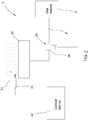
- a conventional gas appliance 1 includes a burner 10, a gas valve 12, and a pressure regulator 14, wherein the burner 10 is adapted to burn gas to generate flames; the gas valve 12 communicates with the burner 10 and is adapted to regulate a gas flow rate supplying to the burner 10 manually or automatically; one end of the pressure regulator 14 is connected to the gas valve 12, and another end of the pressure regulator 14 is connected to a gas source 16 (e.g. liquefied petroleum gas or natural gas).
- a gas source 16 e.g. liquefied petroleum gas or natural gas
- the conventional gas appliance 1 it is required for the conventional gas appliance 1 to utilize the pressure regulator 14 to stabilize a pressure output from the gas source 16 to the gas valve 12.
- the pressure output from the gas source 16 is smaller than a certain pressure, the pressure output from the pressure regulator 14 would be unstable.
- the gas valve 12 is adapted to regulate the gas flow rate by changing an opening degree of an opening, the gas flow rate would be unstable when the pressure supplying to the gas valve 12 is unstable, thereby affecting the combustion efficiency of the burner 10.
- an object of the present invention is to provide a gas valve which could stabilize a gas flow rate.
- the present invention provides a gas valve including a valve body, a flow regulator, a hot film anemometer, and a driver, wherein the valve body includes an air inlet, an air outlet, an inlet passage communicating with the air inlet, an outlet passage communicating with the air outlet, and an opening disposed between the inlet passage and the outlet passage; the flow regulator is movably disposed at the openi ng of the valve body and is driven to change an openi ng degree of the opening; the hot film anemometer is disposed in the valve body and includes a probe which includes a hot film resistor exposed to the outlet passage to sense a gas flow rate passing through the outlet passage; the driver is disposed in the valve body and connected to the flow regulator, and is adapted to receive a control signal to drive the flow regulator to move.
- the advantage of the present invention is that a variation of the gas flow rate could be sensed accurately and rapidly by disposing the hot film anemometer in the outlet passage, whereby to control the stepper motor and stabilize the gas flow rate passing through the gas valve without disposing the pressure regulator. In this way, the gas flow rate could be controlled more accurately and the manufacturing cost of the gas appliance could be reduced.
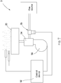
- a gas appliance 2 of a first embodiment includes a burner 20, an ignitor 22, a flame detector 24, a gas valve 26, and a control device 52.
- the gas appliance 2 could be a gas heating device such as a gas stove, a fireplace, or a water heater for example.
- the burner 20 is adapted to burn gas to generate flames.
- the ignitor 22 is disposed adjacent to the burner 20 and is controllable to generate sparks with respect to the burner 20 so as to ignite the gas output from the burner 20.
- the flame detector 24 is disposed adjacent to the burner 20 to detect the flames.
- the flame detector 24 could be a thermocouple or a flame sensor as an example.
- the gas valve 26 is disposed on a gas pipe P which communicates with the burner 20.
- the gas valve 26 is controllable to open and block the gas pipe P and regulate the gas flow rate supplying to the burner 20.
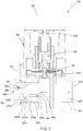
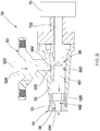
- the gas valve 26 includes a valve body 28, a flow regulator 34, a hot film anemometer 38, and a driver which is a stepper motor 50 as an example.
- the valve body 28 includes an air inlet 301, an air outlet 324, an inlet passage 303 communicating with the air inlet 301, an outlet passage 322 communicating with the air outlet 324, and an opening 304 disposed between the inlet passage 303 and the outlet passage 322.
- the air inlet 301 is adapted to be connected to a gas source G, and the air outlet 324 communicates with the burner 20.
- the air inlet 301 directly communicates with the gas source G via the gas pipe P, and there is no pressure regulator 14, which is used in a conventional gas appliance, disposed between the air inlet 301 and the gas source G.
- the valve body 28 includes a main body 30 and a tube 32, wherein the main body 30 includes the air inlet 301, the inlet passage 303, the opening 304, and a connecting passage 305; the opening 304 is disposed between the inlet passage 303 and the connecting passage 305.
- the tube 32 is connected to the connecting passage 305 and includes the outlet passage 322 and the air outlet 324.
- the outlet passage 322 includes a first secti on 322a, a second secti on 322b, and a third secti on 322c, wherein the first secti on 322a is between the second secti on 322b and the third secti on 322c.
- the first section 322a is tapered and has an internal diameter which is gradually decreased in a direction from the third secti on 322c to the second secti on 322b; the second secti on 322b is equal-diameter and is between the first section 322a and the air outlet 324.
- the connecti ng passage 305 has an internal thread.
- the tube 30 includes a threaded tube 32a and an outer tube 32b which are connected to each other, wherein the threaded tube 32a is engaged with the internal thread of the connecting passage 305; the outer tube 32b includes at least a part of the second section 322b and is disposed outside of the main body 30.
- the hot film anemometer 38 is disposed in the outer tube 32b. More specifically, the outer tube 32b includes a recess 326 which is recessed from a wall of the second section 322b.
- the outer tube 32b forms a head which is a hexagon head as an example, and the head is rotatable such that the threaded tube 32a could be screwed to the connecting passage 305.
- a seal ring is disposed between the outer tube 32b and the main body 30 to prevent the gas from leaking out.
- the flow regulator 34 is movably disposed at the openi ng 304 of the valve body 28.
- the flow regulator 34 is a valve plug as an example, and is connected to a transmission mechanism 36, wherein the transmission mechanism 36 is driven to change an opening degree of the opening 304.
- the hot film anemometer 38 is disposed in the valve body 28.
- the hot film anemometer 38 includes a probe 38a exposed to the outlet passage 322 to sense the gas flow rate passing through the outlet passage 322.
- the hot film anemometer 38 includes a substrate 40, and a hot film resistor 402 and a compensation resistor 404 which are disposed on the substrate 40, wherein the hot film resistor 402 and the compensation resistor 404 are exposed to the outlet passage 322.
- the probe 38a includes the hot film resistor 402 and the compensation resistor 404, and a resistance of the hot film resistor 402 is smaller than a resistance of the compensation resistor 404.
- the probe 38a could only include the hot film resistor 402 exposed to the outlet passage 322.
- the hot film anemometer 38 is disposed in the recess 326, and the probe 38a of the hot film anemometer 38 is exposed to the second section 322b.
- the hot film anemometer 38 is electronically connected to an external circuit via a signal wire 44 extending out of the outer tube 32b of the tube 32.
- a nother two resistors 406, 408 are further disposed on the substrate 40 and form a bridge circuit 40a together with the hot film resistor 402 and the compensation resistor 404, wherein each one end of the hot film resistor 402 and the compensation resistor 404 is connected to a first node 421, and the first node 421 is adapted to be connected to a power supply; each one end of the another two resistors 406, 408 is connected to a second node 422, and the second node 422 is adapted to be connected to a grounding terminal.
- the hot film resistor 402 When the power is supplied, the hot film resistor 402 would generate heat, and meanwhile, when the gas flow F passing through the hot film resistor 402 increases, the hot film resistor 402 would be cooled down and the resistance thereof would become small and the current thereof would increase.
- the current of the compensation resistor 404 increases as well, thereby raising the temperature of the hot film resistor 402 again, and vice versa.
- the current of the compensation resistor 404 and the gas flow rate are proportional and corresponding to each other.
- the voltage between a third node 423 and a fourth node 424 of the bridge circuit 40a would be proportional to the gas flow rate.
- the first node 421, the second node 422, the third node 423, and the fourth node 424 are connected to outside of the valve body 28 via the signal wire 44.
- the third node 423 and the fourth node 424 are connected to an amplifying circuit 522, wherein the amplifying circuit 522 is disposed outside of the valve body 28 and adapted to amplify the voltage between the third node 423 and the fourth node 424.
- the amplifying circuit 522 could be disposed on the substrate 40 as well.
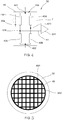
- the gas valve 26 provided by this embodiment further includes a flow guiding member 48.
- the flow guiding member 48 is disposed in the third section 322c of the outlet passage 322 of the tube 32, and the probe 38a of the hot film anemometer 38 is disposed between the flow guiding member 48 and the air outlet 324.
- the flow guiding member 48 includes a plurality of sub-passages 482 (as shown in FIG. 3 and FIG. 5 ) which could guide the gas flow F to pass through the probe 38a fluently, thereby reducing a detection error which is caused by the turbulent flow.
- T he stepper motor 50 is disposed in the valve body 28 and connected to the flow regulator 34.
- the stepper motor 50 is adapted to receive a control signal to drive the flow regulator 34 to move.
- a rotary shaft 502 of the stepper motor 50 is connected to the flow regulator 34 via the transmission mechanism 36.
- the flow regulator 34 would be driven to move along an axial direction of the rotary shaft 502, thereby changing the opening degree of the opening 304.
- the control device 52 is electronically connected to the ignitor 22, the flame detector 24, the hot film anemometer 38, and the stepper motor 50.
- the control device 52 includes the power supply and the grounding terminal, and is adapted to supply power to the bridge circuit 40a on the substrate 40 of the hot film anemometer 38 via the signal wire 44.
- the control device 52 further includes the amplifying circuit 522 and is electronically connected to the bridge circuit 40a via the signal wire 44 to receive the voltage between the third node 423 and the fourth node 424 of the bridge circuit 40a.
- the control device 52 is adapted to execute a control method for the gas valve 26 in this embodiment.
- the control device 52 would control the ignitor 22 to generate sparks with respect to the burner 10 fi rst.
- control method for the gas valve 26 is executed, wherein the control method includes the following steps, which are shown in FIG. 6 .
- the control device 52 outputs the control signal to control the stepper motor 50 to drive the flow regulator 34 to open the openi ng 304 for passing the gas; when the gas is ignited, the control device 52 would be informed of the ignition via an electrical signal sendi ng back from the flame detector 24.
- the hot film anemometer 38 is adapted to sense the gas flow rate in the outlet passage 322; in this embodiment, the control device 52 would convert the voltage output from the bridge circuit 40a of the hot film anemometer 38 into a corresponding gas flow rate.
- the control device 52 is adapted to control the stepper motor 50 to drive the flow regulator 34 by outputting the control signal based on a predetermined gas flow rate and the gas flow rate sensed by the hot film anemometer 38, thereby enabling the gas flow rate sensed by the hot film anemometer 38 to be maintained at the predetermined gas flow rate. More particularly, the control device 52 would compare the gas flow rate sensed by the hot film anemometer 38 with the predetermined gas flow rate, and control the stepper motor 50 to drive the flow regulator 34 based on the comparison result such that the gas flow rate sensed by the hot film anemometer 38 could be maintained at the predetermined gas flow rate.
- the predetermined gas flow rate is corresponding to a predetermined heating value.
- the gas flow rate supplyiNg to the burner 20 is equal to the predetermined gas flow rate, the burner 20 would generate the predetermined heating value.
- the gas flow rate output from the gas valve 26 still could be stably maintained at the predetermined gas flow rate through controlling the flow regulator 34.
- the advantage of the hot film anemometer 38 is that the gas flow rate could be sensed rapidly, hence, the stepper motor 50 could be controlled instantly and the gas flow rate could be maintained at the predetermined gas flow rate rapidly. Since the hot film anemometer 38 is disposed between the opening 304 and the air outlet 324, the gas flow rate has been regulated by the flow regulator 34 already and the gas flow rate passing through the hot film anemometer 38 would be more stable.
- a gas appliance of a second embodiment according to the present invention has almost the same structure as the gas appliance of the first embodiment, except that the gas appliance provided by the second embodiment further includes a mixer 54 and a blower 56, wherein the mixer 54 is disposed between the gas valve 26 and the burner 20.
- the blower 56 is electronically connected to the control device 52 and an air outlet of the blower 56 is connected to the mixer 54.
- the control device 52 generates a predetermined rotation speed and a predetermined gas flow rate according to a predetermined heating value, wherein the control device 52 controls a rotation speed of a motor of the blower 56 according to the predetermined rotation speed, and controls the stepper motor 50 to drive the flow regulator 34 according to the predetermined gas flow rate and the gas flow rate sensed by the hot film anemometer 38, thereby enabling the gas flow rate sensed by the hot film anemometer 38 to be mai ntai ned at the predetermined gas flow rate.
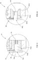
- a gas valve 58 of a third embodiment is illustrated and has a structure similar to the gas valve 26 of the first embodi ment.
- the gas valve 58 includes a valve body 60, a flow regulator 66, a hot film anemometer 68, and a stepper motor 70.
- the valve body 60 provided by this embodiment includes a main body 62 and a tube 64, wherein the main body 62 includes an air inlet 622, an inlet passage 624, an openi ng 626, and a connecti ng passage 628; the tube 64 has the same structure as the tube 32 of the first embodiment, and includes an outlet passage 642 and an air outlet 644.
- the flow regulator 66 provided by this embodi ment is a plug member as an example, and is rotatably disposed in the main body 62.
- the flow regulator 66 includes an axial hole 661, a first hole 662, a second hole 663, a first guiding groove 664, and a second guiding groove 665, wherein the first hole 662 and the second hole 663 communicate with the axial hole 661, and a diameter of the first hole 662 is greater than a diameter of the second hole 663.
- the first guiding groove 664 and the second guiding groove 665 are disposed between the first hole 662 and the second hole 663; one end of the first guidi ng groove 664 is connected to the first hole 662, and one end of the second guiding groove 665 is connected to the second hole 663.
- the flow regulator 66 could only include the axial hole 661, the first hole 662, and the first guiding groove 664.
- the hot film anemometer 68 is disposed in the valve body 60.
- the stepper motor 70 is disposed with the main body 62, and a rotary shaft 702 of the stepper motor 70 is connected to the plug member.
- the gas valve 58 provided by this embodiment could be adapted to the gas appliance 2 of the first embodi ment as well.
- a gas valve 72 of a fourth embodiment according to the present invention has almost the same structure as the gas valve 26 of the first embodiment, except that a first section 742a and a second section 742b of an outlet passage 742 of a tube 74 have identical internal diameters, that is, the outlet passage 742 between a flow guiding member 76 and the hot film anemometer 38 has an equal internal diameter.
- the gas flow F could pass through the probe 38a of the hot film anemometer 38 more stably.
- a gas valve 78 of a fifth embodiment has almost the same structure as the gas valve 26 of the first embodiment, except that a first section 802a and a second section 802b of an outlet passage 802 of a tube 80 have identical internal diameters, while a third section 802c is tapered, and a flow guiding member 82 is disposed in the first section 802a.
- the outlet passage 802 between the flow guiding member 82 and the hot film anemometer 38 has an equal internal diameter. Whereby, the gas flow F could pass through the probe 38a of the hot film anemometer 38 more stably as well.
- the outlet passage 642 of the tube 64 of the third embodiment also could adopt the structures of the tube 74, 80 of the fourth and the fifth embodiments.
- the driver of each of the aforementioned embodiments is a stepper motor as an example.
- the gas valve could also be a proportional valve as an example, as disclosed in United States patent publication number US20090206291A1 .
- a driver of the proportional valve includes a coil and a magnet, which could drive a flow regulator to change an opening degree of an opening via an electromagnetic force.
- the variation of the gas flow rate could be sensed accurately and rapidly by disposing the hot film anemometer in the outlet passage, whereby to control the stepper motor and stabilize the gas flow rate passing through the gas valve without disposing the pressure regulator.
- the gas flow rate could be controlled more accurately and the manufacturing cost of the gas appliance could be reduced.
Landscapes
- Engineering & Computer Science (AREA)
- Chemical & Material Sciences (AREA)
- Combustion & Propulsion (AREA)
- Mechanical Engineering (AREA)
- General Engineering & Computer Science (AREA)
- Feeding And Controlling Fuel (AREA)
- Measuring Volume Flow (AREA)
Applications Claiming Priority (1)
| Application Number | Priority Date | Filing Date | Title |
|---|---|---|---|
| TW107102681A TWI669464B (zh) | 2018-01-25 | 2018-01-25 | 瓦斯器具與瓦斯閥及其控制方法 |
Publications (2)
| Publication Number | Publication Date |
|---|---|
| EP3517841A1 true EP3517841A1 (de) | 2019-07-31 |
| EP3517841B1 EP3517841B1 (de) | 2022-02-16 |
Family
ID=62814828
Family Applications (1)
| Application Number | Title | Priority Date | Filing Date |
|---|---|---|---|
| EP18180056.6A Active EP3517841B1 (de) | 2018-01-25 | 2018-06-27 | Gasventil |
Country Status (3)
| Country | Link |
|---|---|
| US (1) | US11060724B2 (de) |
| EP (1) | EP3517841B1 (de) |
| TW (1) | TWI669464B (de) |
Cited By (2)
| Publication number | Priority date | Publication date | Assignee | Title |
|---|---|---|---|---|
| US10871235B1 (en) | 2019-08-07 | 2020-12-22 | Grand Mate Co., Ltd. | Flow regulating valve of gas stove |
| EP3779279A1 (de) * | 2019-08-13 | 2021-02-17 | Grand Mate Co., Ltd. | Durchflussregelventil für gasofen |
Families Citing this family (3)
| Publication number | Priority date | Publication date | Assignee | Title |
|---|---|---|---|---|
| US8008386B2 (en) | 2006-12-25 | 2011-08-30 | Kaneka Corporation | Curable composition |
| US11732890B2 (en) | 2020-09-30 | 2023-08-22 | Midea Group Co., Ltd. | Cooking appliance gas oven burner control during oven warm-up operation |
| US11739933B2 (en) | 2020-09-30 | 2023-08-29 | Midea Group Co., Ltd. | Oven broiler gas burner for cooking appliance with variable electromechanical valve |
Citations (5)
| Publication number | Priority date | Publication date | Assignee | Title |
|---|---|---|---|---|
| EP0064560A1 (de) * | 1980-11-21 | 1982-11-17 | Yamatake-Honeywell Co. Ltd. | Sicherheitsabschliessventil |
| US5762880A (en) * | 1996-12-16 | 1998-06-09 | Megtec Systems, Inc. | Operational process and its improved control system of a secondary air burner |
| US20090206291A1 (en) | 2008-02-20 | 2009-08-20 | Grand Mate Co. Ltd. | Gas flow rate control valve |
| EP2589868A1 (de) * | 2011-11-07 | 2013-05-08 | Honeywell Technologies Sarl | Verfahren zum Betreiben eines Gasbrenners |
| US20170059170A1 (en) * | 2015-08-28 | 2017-03-02 | Grand Mate Co., Ltd | Method For Controlling Gas-Fired Appliance |
Family Cites Families (19)
| Publication number | Priority date | Publication date | Assignee | Title |
|---|---|---|---|---|
| JP3385307B2 (ja) * | 1998-05-11 | 2003-03-10 | 三菱電機株式会社 | 流量センサ |
| DE19824521B4 (de) * | 1998-06-02 | 2004-12-23 | Honeywell B.V. | Regeleinrichtung für Gasbrenner |
| DE10027831C2 (de) * | 2000-06-05 | 2002-08-01 | Siemens Ag | Massenstrommesser |
| CN2777389Y (zh) * | 2005-02-05 | 2006-05-03 | 叶克斌 | 煤气灶自动控制器 |
| US20100170483A1 (en) * | 2007-04-26 | 2010-07-08 | Heraeus Sensor Technology Gmbh | Film resistor in an exhaust-gas pipe |
| TW200925522A (en) * | 2007-12-07 | 2009-06-16 | Yi-Hua Huang | Flow calibrating method for gas regulating valve and calibrating step thereof |
| CN102353806B (zh) | 2011-06-24 | 2012-09-05 | 清华大学 | 热敏流速传感器温度补偿电路及方法和功率自动调节方法 |
| CN102954500A (zh) | 2011-08-26 | 2013-03-06 | 关隆股份有限公司 | 瓦斯器具及其调控方法 |
| JPWO2013099916A1 (ja) * | 2011-12-28 | 2015-05-07 | 川崎重工業株式会社 | 流速分布均一化装置 |
| DE102012102094A1 (de) * | 2012-03-13 | 2013-09-19 | Pierburg Gmbh | Vorrichtung zur Bestimmung eines Gasmassenstroms sowie Verfahren zur Rekalibrierung einer derartigen Vorrichtung |
| CN103867765A (zh) | 2012-12-10 | 2014-06-18 | 关隆股份有限公司 | 瓦斯控制阀及使用该瓦斯控制阀的瓦斯燃烧器具 |
| US9857805B2 (en) * | 2013-02-18 | 2018-01-02 | Flo Technologies, Inc. | Fluid monitoring and control system |
| US9477237B2 (en) * | 2013-06-03 | 2016-10-25 | Tescom Corporation | Pilot operated gas regulator with diaphragm protection |
| TWI567347B (zh) * | 2013-10-18 | 2017-01-21 | Grand Mate Co Ltd | Gas regulator |
| CN104633131B (zh) | 2013-11-07 | 2017-10-20 | 关隆股份有限公司 | 瓦斯调压器 |
| CN105402766B (zh) | 2014-09-10 | 2018-09-11 | 关隆股份有限公司 | 用于瓦斯器具的瓦斯阀控制方法 |
| CN106641310B (zh) | 2015-11-02 | 2019-11-15 | 关隆股份有限公司 | 瓦斯阀的闭子 |
| US10274353B2 (en) * | 2017-03-22 | 2019-04-30 | A. O. Smith Corporation | Flow sensor with hot film anemometer |
| CN208041252U (zh) | 2018-03-20 | 2018-11-02 | 关隆股份有限公司 | 瓦斯器具与瓦斯阀 |
-
2018
- 2018-01-25 TW TW107102681A patent/TWI669464B/zh active
- 2018-06-21 US US16/014,174 patent/US11060724B2/en active Active
- 2018-06-27 EP EP18180056.6A patent/EP3517841B1/de active Active
Patent Citations (5)
| Publication number | Priority date | Publication date | Assignee | Title |
|---|---|---|---|---|
| EP0064560A1 (de) * | 1980-11-21 | 1982-11-17 | Yamatake-Honeywell Co. Ltd. | Sicherheitsabschliessventil |
| US5762880A (en) * | 1996-12-16 | 1998-06-09 | Megtec Systems, Inc. | Operational process and its improved control system of a secondary air burner |
| US20090206291A1 (en) | 2008-02-20 | 2009-08-20 | Grand Mate Co. Ltd. | Gas flow rate control valve |
| EP2589868A1 (de) * | 2011-11-07 | 2013-05-08 | Honeywell Technologies Sarl | Verfahren zum Betreiben eines Gasbrenners |
| US20170059170A1 (en) * | 2015-08-28 | 2017-03-02 | Grand Mate Co., Ltd | Method For Controlling Gas-Fired Appliance |
Cited By (2)
| Publication number | Priority date | Publication date | Assignee | Title |
|---|---|---|---|---|
| US10871235B1 (en) | 2019-08-07 | 2020-12-22 | Grand Mate Co., Ltd. | Flow regulating valve of gas stove |
| EP3779279A1 (de) * | 2019-08-13 | 2021-02-17 | Grand Mate Co., Ltd. | Durchflussregelventil für gasofen |
Also Published As
| Publication number | Publication date |
|---|---|
| US11060724B2 (en) | 2021-07-13 |
| TWI669464B (zh) | 2019-08-21 |
| TW201932760A (zh) | 2019-08-16 |
| US20190226678A1 (en) | 2019-07-25 |
| EP3517841B1 (de) | 2022-02-16 |
Similar Documents
| Publication | Publication Date | Title |
|---|---|---|
| EP3517841A1 (de) | Gasventil | |
| CN106642711B (zh) | 双传感燃烧系统 | |
| US7252502B2 (en) | Method and system for combined standing pilot safety and temperature setting | |
| US11149946B2 (en) | System and approach for controlling a combustion chamber | |
| US5685707A (en) | Integrated burner assembly | |
| EP4400767A2 (de) | Closed-loop-programmierung und -steuerung eines verbrennungsgeräts | |
| US10422531B2 (en) | System and approach for controlling a combustion chamber | |
| CN106662323A (zh) | 具有文丘里管阻尼器的可调节燃烧器 | |
| US7435081B2 (en) | Method and system for pilot light safety | |
| US20170199530A1 (en) | Pressure regulator | |
| US11874028B2 (en) | Modulating gas orifice | |
| US8028968B2 (en) | Variable orifice gas flow modulating valve | |
| TWM562369U (zh) | 瓦斯器具與瓦斯閥 | |
| RS59606B1 (sr) | Uređaj za upravljanje sagorevanjem u gorioniku | |
| CN101115955A (zh) | 使用空气压力传感器控制燃油炉合适燃烧比的系统及方法 | |
| CN208041252U (zh) | 瓦斯器具与瓦斯阀 | |
| US10969143B2 (en) | Method for detecting a non-closing water heater main gas valve | |
| US20260117973A1 (en) | Method and system for controlling operation of an inducer motor of a combustion system | |
| CN115493165B (zh) | 一种燃气具及其控制方法 | |
| JP2939135B2 (ja) | ガス燃焼装置 | |
| JP2644415B2 (ja) | 強制送風式燃焼装置 | |
| CN110307371A (zh) | 瓦斯器具与瓦斯阀及其控制方法 | |
| US20150118631A1 (en) | Method and device for controlling excess air in a furnace | |
| HK1232586A1 (en) | Modulating burner with venturi damper | |
| JP2000018568A (ja) | 燃焼装置 |
Legal Events
| Date | Code | Title | Description |
|---|---|---|---|
| PUAI | Public reference made under article 153(3) epc to a published international application that has entered the european phase |
Free format text: ORIGINAL CODE: 0009012 |
|
| STAA | Information on the status of an ep patent application or granted ep patent |
Free format text: STATUS: THE APPLICATION HAS BEEN PUBLISHED |
|
| AK | Designated contracting states |
Kind code of ref document: A1 Designated state(s): AL AT BE BG CH CY CZ DE DK EE ES FI FR GB GR HR HU IE IS IT LI LT LU LV MC MK MT NL NO PL PT RO RS SE SI SK SM TR |
|
| AX | Request for extension of the european patent |
Extension state: BA ME |
|
| STAA | Information on the status of an ep patent application or granted ep patent |
Free format text: STATUS: REQUEST FOR EXAMINATION WAS MADE |
|
| 17P | Request for examination filed |
Effective date: 20200124 |
|
| RBV | Designated contracting states (corrected) |
Designated state(s): AL AT BE BG CH CY CZ DE DK EE ES FI FR GB GR HR HU IE IS IT LI LT LU LV MC MK MT NL NO PL PT RO RS SE SI SK SM TR |
|
| GRAP | Despatch of communication of intention to grant a patent |
Free format text: ORIGINAL CODE: EPIDOSNIGR1 |
|
| STAA | Information on the status of an ep patent application or granted ep patent |
Free format text: STATUS: GRANT OF PATENT IS INTENDED |
|
| INTG | Intention to grant announced |
Effective date: 20210906 |
|
| GRAS | Grant fee paid |
Free format text: ORIGINAL CODE: EPIDOSNIGR3 |
|
| GRAA | (expected) grant |
Free format text: ORIGINAL CODE: 0009210 |
|
| STAA | Information on the status of an ep patent application or granted ep patent |
Free format text: STATUS: THE PATENT HAS BEEN GRANTED |
|
| AK | Designated contracting states |
Kind code of ref document: B1 Designated state(s): AL AT BE BG CH CY CZ DE DK EE ES FI FR GB GR HR HU IE IS IT LI LT LU LV MC MK MT NL NO PL PT RO RS SE SI SK SM TR |
|
| REG | Reference to a national code |
Ref country code: GB Ref legal event code: FG4D |
|
| REG | Reference to a national code |
Ref country code: CH Ref legal event code: EP |
|
| REG | Reference to a national code |
Ref country code: DE Ref legal event code: R096 Ref document number: 602018030814 Country of ref document: DE |
|
| REG | Reference to a national code |
Ref country code: AT Ref legal event code: REF Ref document number: 1469099 Country of ref document: AT Kind code of ref document: T Effective date: 20220315 |
|
| REG | Reference to a national code |
Ref country code: IE Ref legal event code: FG4D |
|
| REG | Reference to a national code |
Ref country code: LT Ref legal event code: MG9D |
|
| REG | Reference to a national code |
Ref country code: NL Ref legal event code: MP Effective date: 20220216 |
|
| REG | Reference to a national code |
Ref country code: AT Ref legal event code: MK05 Ref document number: 1469099 Country of ref document: AT Kind code of ref document: T Effective date: 20220216 |
|
| PG25 | Lapsed in a contracting state [announced via postgrant information from national office to epo] |
Ref country code: SE Free format text: LAPSE BECAUSE OF FAILURE TO SUBMIT A TRANSLATION OF THE DESCRIPTION OR TO PAY THE FEE WITHIN THE PRESCRIBED TIME-LIMIT Effective date: 20220216 Ref country code: RS Free format text: LAPSE BECAUSE OF FAILURE TO SUBMIT A TRANSLATION OF THE DESCRIPTION OR TO PAY THE FEE WITHIN THE PRESCRIBED TIME-LIMIT Effective date: 20220216 Ref country code: PT Free format text: LAPSE BECAUSE OF FAILURE TO SUBMIT A TRANSLATION OF THE DESCRIPTION OR TO PAY THE FEE WITHIN THE PRESCRIBED TIME-LIMIT Effective date: 20220616 Ref country code: NO Free format text: LAPSE BECAUSE OF FAILURE TO SUBMIT A TRANSLATION OF THE DESCRIPTION OR TO PAY THE FEE WITHIN THE PRESCRIBED TIME-LIMIT Effective date: 20220516 Ref country code: NL Free format text: LAPSE BECAUSE OF FAILURE TO SUBMIT A TRANSLATION OF THE DESCRIPTION OR TO PAY THE FEE WITHIN THE PRESCRIBED TIME-LIMIT Effective date: 20220216 Ref country code: LT Free format text: LAPSE BECAUSE OF FAILURE TO SUBMIT A TRANSLATION OF THE DESCRIPTION OR TO PAY THE FEE WITHIN THE PRESCRIBED TIME-LIMIT Effective date: 20220216 Ref country code: HR Free format text: LAPSE BECAUSE OF FAILURE TO SUBMIT A TRANSLATION OF THE DESCRIPTION OR TO PAY THE FEE WITHIN THE PRESCRIBED TIME-LIMIT Effective date: 20220216 Ref country code: ES Free format text: LAPSE BECAUSE OF FAILURE TO SUBMIT A TRANSLATION OF THE DESCRIPTION OR TO PAY THE FEE WITHIN THE PRESCRIBED TIME-LIMIT Effective date: 20220216 Ref country code: BG Free format text: LAPSE BECAUSE OF FAILURE TO SUBMIT A TRANSLATION OF THE DESCRIPTION OR TO PAY THE FEE WITHIN THE PRESCRIBED TIME-LIMIT Effective date: 20220516 |
|
| PG25 | Lapsed in a contracting state [announced via postgrant information from national office to epo] |
Ref country code: PL Free format text: LAPSE BECAUSE OF FAILURE TO SUBMIT A TRANSLATION OF THE DESCRIPTION OR TO PAY THE FEE WITHIN THE PRESCRIBED TIME-LIMIT Effective date: 20220216 Ref country code: LV Free format text: LAPSE BECAUSE OF FAILURE TO SUBMIT A TRANSLATION OF THE DESCRIPTION OR TO PAY THE FEE WITHIN THE PRESCRIBED TIME-LIMIT Effective date: 20220216 Ref country code: GR Free format text: LAPSE BECAUSE OF FAILURE TO SUBMIT A TRANSLATION OF THE DESCRIPTION OR TO PAY THE FEE WITHIN THE PRESCRIBED TIME-LIMIT Effective date: 20220517 Ref country code: FI Free format text: LAPSE BECAUSE OF FAILURE TO SUBMIT A TRANSLATION OF THE DESCRIPTION OR TO PAY THE FEE WITHIN THE PRESCRIBED TIME-LIMIT Effective date: 20220216 Ref country code: AT Free format text: LAPSE BECAUSE OF FAILURE TO SUBMIT A TRANSLATION OF THE DESCRIPTION OR TO PAY THE FEE WITHIN THE PRESCRIBED TIME-LIMIT Effective date: 20220216 |
|
| PG25 | Lapsed in a contracting state [announced via postgrant information from national office to epo] |
Ref country code: IS Free format text: LAPSE BECAUSE OF FAILURE TO SUBMIT A TRANSLATION OF THE DESCRIPTION OR TO PAY THE FEE WITHIN THE PRESCRIBED TIME-LIMIT Effective date: 20220617 |
|
| PG25 | Lapsed in a contracting state [announced via postgrant information from national office to epo] |
Ref country code: SM Free format text: LAPSE BECAUSE OF FAILURE TO SUBMIT A TRANSLATION OF THE DESCRIPTION OR TO PAY THE FEE WITHIN THE PRESCRIBED TIME-LIMIT Effective date: 20220216 Ref country code: SK Free format text: LAPSE BECAUSE OF FAILURE TO SUBMIT A TRANSLATION OF THE DESCRIPTION OR TO PAY THE FEE WITHIN THE PRESCRIBED TIME-LIMIT Effective date: 20220216 Ref country code: RO Free format text: LAPSE BECAUSE OF FAILURE TO SUBMIT A TRANSLATION OF THE DESCRIPTION OR TO PAY THE FEE WITHIN THE PRESCRIBED TIME-LIMIT Effective date: 20220216 Ref country code: EE Free format text: LAPSE BECAUSE OF FAILURE TO SUBMIT A TRANSLATION OF THE DESCRIPTION OR TO PAY THE FEE WITHIN THE PRESCRIBED TIME-LIMIT Effective date: 20220216 Ref country code: DK Free format text: LAPSE BECAUSE OF FAILURE TO SUBMIT A TRANSLATION OF THE DESCRIPTION OR TO PAY THE FEE WITHIN THE PRESCRIBED TIME-LIMIT Effective date: 20220216 Ref country code: CZ Free format text: LAPSE BECAUSE OF FAILURE TO SUBMIT A TRANSLATION OF THE DESCRIPTION OR TO PAY THE FEE WITHIN THE PRESCRIBED TIME-LIMIT Effective date: 20220216 |
|
| REG | Reference to a national code |
Ref country code: DE Ref legal event code: R097 Ref document number: 602018030814 Country of ref document: DE |
|
| PG25 | Lapsed in a contracting state [announced via postgrant information from national office to epo] |
Ref country code: AL Free format text: LAPSE BECAUSE OF FAILURE TO SUBMIT A TRANSLATION OF THE DESCRIPTION OR TO PAY THE FEE WITHIN THE PRESCRIBED TIME-LIMIT Effective date: 20220216 |
|
| PLBE | No opposition filed within time limit |
Free format text: ORIGINAL CODE: 0009261 |
|
| STAA | Information on the status of an ep patent application or granted ep patent |
Free format text: STATUS: NO OPPOSITION FILED WITHIN TIME LIMIT |
|
| 26N | No opposition filed |
Effective date: 20221117 |
|
| PG25 | Lapsed in a contracting state [announced via postgrant information from national office to epo] |
Ref country code: MC Free format text: LAPSE BECAUSE OF FAILURE TO SUBMIT A TRANSLATION OF THE DESCRIPTION OR TO PAY THE FEE WITHIN THE PRESCRIBED TIME-LIMIT Effective date: 20220216 |
|
| REG | Reference to a national code |
Ref country code: CH Ref legal event code: PL |
|
| REG | Reference to a national code |
Ref country code: BE Ref legal event code: MM Effective date: 20220630 |
|
| PG25 | Lapsed in a contracting state [announced via postgrant information from national office to epo] |
Ref country code: SI Free format text: LAPSE BECAUSE OF FAILURE TO SUBMIT A TRANSLATION OF THE DESCRIPTION OR TO PAY THE FEE WITHIN THE PRESCRIBED TIME-LIMIT Effective date: 20220216 |
|
| PG25 | Lapsed in a contracting state [announced via postgrant information from national office to epo] |
Ref country code: LU Free format text: LAPSE BECAUSE OF NON-PAYMENT OF DUE FEES Effective date: 20220627 Ref country code: LI Free format text: LAPSE BECAUSE OF NON-PAYMENT OF DUE FEES Effective date: 20220630 Ref country code: IE Free format text: LAPSE BECAUSE OF NON-PAYMENT OF DUE FEES Effective date: 20220627 Ref country code: FR Free format text: LAPSE BECAUSE OF NON-PAYMENT OF DUE FEES Effective date: 20220630 Ref country code: CH Free format text: LAPSE BECAUSE OF NON-PAYMENT OF DUE FEES Effective date: 20220630 |
|
| PG25 | Lapsed in a contracting state [announced via postgrant information from national office to epo] |
Ref country code: BE Free format text: LAPSE BECAUSE OF NON-PAYMENT OF DUE FEES Effective date: 20220630 |
|
| P01 | Opt-out of the competence of the unified patent court (upc) registered |
Effective date: 20230626 |
|
| PG25 | Lapsed in a contracting state [announced via postgrant information from national office to epo] |
Ref country code: HU Free format text: LAPSE BECAUSE OF FAILURE TO SUBMIT A TRANSLATION OF THE DESCRIPTION OR TO PAY THE FEE WITHIN THE PRESCRIBED TIME-LIMIT; INVALID AB INITIO Effective date: 20180627 |
|
| PG25 | Lapsed in a contracting state [announced via postgrant information from national office to epo] |
Ref country code: MK Free format text: LAPSE BECAUSE OF FAILURE TO SUBMIT A TRANSLATION OF THE DESCRIPTION OR TO PAY THE FEE WITHIN THE PRESCRIBED TIME-LIMIT Effective date: 20220216 Ref country code: CY Free format text: LAPSE BECAUSE OF FAILURE TO SUBMIT A TRANSLATION OF THE DESCRIPTION OR TO PAY THE FEE WITHIN THE PRESCRIBED TIME-LIMIT Effective date: 20220216 |
|
| PG25 | Lapsed in a contracting state [announced via postgrant information from national office to epo] |
Ref country code: MT Free format text: LAPSE BECAUSE OF FAILURE TO SUBMIT A TRANSLATION OF THE DESCRIPTION OR TO PAY THE FEE WITHIN THE PRESCRIBED TIME-LIMIT Effective date: 20220216 |
|
| PGFP | Annual fee paid to national office [announced via postgrant information from national office to epo] |
Ref country code: DE Payment date: 20250611 Year of fee payment: 8 |
|
| PGFP | Annual fee paid to national office [announced via postgrant information from national office to epo] |
Ref country code: GB Payment date: 20250604 Year of fee payment: 8 |
|
| PGFP | Annual fee paid to national office [announced via postgrant information from national office to epo] |
Ref country code: IT Payment date: 20250617 Year of fee payment: 8 |
|
| PG25 | Lapsed in a contracting state [announced via postgrant information from national office to epo] |
Ref country code: TR Free format text: LAPSE BECAUSE OF FAILURE TO SUBMIT A TRANSLATION OF THE DESCRIPTION OR TO PAY THE FEE WITHIN THE PRESCRIBED TIME-LIMIT Effective date: 20220216 |