EP3517766B1 - Translating lock for pivot door thrust reverser - Google Patents
Translating lock for pivot door thrust reverser Download PDFInfo
- Publication number
- EP3517766B1 EP3517766B1 EP18202158.4A EP18202158A EP3517766B1 EP 3517766 B1 EP3517766 B1 EP 3517766B1 EP 18202158 A EP18202158 A EP 18202158A EP 3517766 B1 EP3517766 B1 EP 3517766B1
- Authority
- EP
- European Patent Office
- Prior art keywords
- blade
- blade member
- thrust reverser
- actuator
- lock
- Prior art date
- Legal status (The legal status is an assumption and is not a legal conclusion. Google has not performed a legal analysis and makes no representation as to the accuracy of the status listed.)
- Active
Links
Images



Classifications
-
- F—MECHANICAL ENGINEERING; LIGHTING; HEATING; WEAPONS; BLASTING
- F02—COMBUSTION ENGINES; HOT-GAS OR COMBUSTION-PRODUCT ENGINE PLANTS
- F02K—JET-PROPULSION PLANTS
- F02K1/00—Plants characterised by the form or arrangement of the jet pipe or nozzle; Jet pipes or nozzles peculiar thereto
- F02K1/54—Nozzles having means for reversing jet thrust
- F02K1/76—Control or regulation of thrust reversers
- F02K1/763—Control or regulation of thrust reversers with actuating systems or actuating devices; Arrangement of actuators for thrust reversers
-
- F—MECHANICAL ENGINEERING; LIGHTING; HEATING; WEAPONS; BLASTING
- F02—COMBUSTION ENGINES; HOT-GAS OR COMBUSTION-PRODUCT ENGINE PLANTS
- F02K—JET-PROPULSION PLANTS
- F02K1/00—Plants characterised by the form or arrangement of the jet pipe or nozzle; Jet pipes or nozzles peculiar thereto
- F02K1/54—Nozzles having means for reversing jet thrust
- F02K1/76—Control or regulation of thrust reversers
- F02K1/766—Control or regulation of thrust reversers with blocking systems or locking devices; Arrangement of locking devices for thrust reversers
-
- F—MECHANICAL ENGINEERING; LIGHTING; HEATING; WEAPONS; BLASTING
- F02—COMBUSTION ENGINES; HOT-GAS OR COMBUSTION-PRODUCT ENGINE PLANTS
- F02K—JET-PROPULSION PLANTS
- F02K1/00—Plants characterised by the form or arrangement of the jet pipe or nozzle; Jet pipes or nozzles peculiar thereto
- F02K1/54—Nozzles having means for reversing jet thrust
- F02K1/56—Reversing jet main flow
- F02K1/60—Reversing jet main flow by blocking the rearward discharge by means of pivoted eyelids or clamshells, e.g. target-type reversers
-
- F—MECHANICAL ENGINEERING; LIGHTING; HEATING; WEAPONS; BLASTING
- F02—COMBUSTION ENGINES; HOT-GAS OR COMBUSTION-PRODUCT ENGINE PLANTS
- F02K—JET-PROPULSION PLANTS
- F02K1/00—Plants characterised by the form or arrangement of the jet pipe or nozzle; Jet pipes or nozzles peculiar thereto
- F02K1/54—Nozzles having means for reversing jet thrust
- F02K1/64—Reversing fan flow
- F02K1/70—Reversing fan flow using thrust reverser flaps or doors mounted on the fan housing
-
- F—MECHANICAL ENGINEERING; LIGHTING; HEATING; WEAPONS; BLASTING
- F05—INDEXING SCHEMES RELATING TO ENGINES OR PUMPS IN VARIOUS SUBCLASSES OF CLASSES F01-F04
- F05D—INDEXING SCHEME FOR ASPECTS RELATING TO NON-POSITIVE-DISPLACEMENT MACHINES OR ENGINES, GAS-TURBINES OR JET-PROPULSION PLANTS
- F05D2220/00—Application
- F05D2220/30—Application in turbines
- F05D2220/32—Application in turbines in gas turbines
-
- F—MECHANICAL ENGINEERING; LIGHTING; HEATING; WEAPONS; BLASTING
- F05—INDEXING SCHEMES RELATING TO ENGINES OR PUMPS IN VARIOUS SUBCLASSES OF CLASSES F01-F04
- F05D—INDEXING SCHEME FOR ASPECTS RELATING TO NON-POSITIVE-DISPLACEMENT MACHINES OR ENGINES, GAS-TURBINES OR JET-PROPULSION PLANTS
- F05D2260/00—Function
- F05D2260/50—Kinematic linkage, i.e. transmission of position
- F05D2260/52—Kinematic linkage, i.e. transmission of position involving springs
Definitions
- the present disclosure relates generally to aircraft thrust reversers used with gas turbine engines and, more particularly, to locking mechanisms used with pivot door thrust reversers.
- Turbofan gas turbine engines are known to include a fan section that produces a bypass airflow for providing the majority of engine propulsion and a core engine section through which a core airflow is compressed, mixed with fuel, combusted and expanded through a turbine to drive the fan section.
- a mixed flow turbofan engine the cool bypass airflow is ducted between a surrounding nacelle and an outer casing of the core engine section and mixed with a hot exhaust stream from the core engine section prior to discharge from the engine nozzle in a combined or mixed exhaust stream.
- the surrounding nacelle may include thrust reversers capable of redirecting the bypass airflow from the rearward direction to, at least partially, a forward direction thus producing a rearward thrust that may serve to decelerate the forward motion of an aircraft and thereby assist braking the aircraft upon landing.
- Pivot door thrust reversers may be used with turbofan gas turbine engines for aircraft, including for corporate or business jets.
- a locking mechanism for a pivot door thrust reverser is disclosed herein.
- a thrust reverser comprising a pivot door and a lock mechanism is disclosed according to claim 1.
- a first component that is "radially outward" of a second component means that the first component is positioned at a greater distance away from a common axis than the second component.
- a first component that is “radially inward” of a second component means that the first component is positioned closer to the common axis than the second component.
- a first component that is radially inward of a second component rotates through a circumferentially shorter path than the second component.
- distal refers to a direction outward or, generally, away from a reference component.
- proximal or “proximate” refer to a direction inward or, generally, towards a reference component.
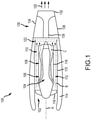
- FIG. 1 schematically illustrates a gas turbine engine 100 of the turbofan variety.
- the gas turbine engine 100 generally includes a fan section 102 and a core engine section 104, which includes a compressor section 106, a combustor section 108 and a turbine section 110.
- the fan section 102 drives air along a bypass flow path B in a bypass duct 112 defined within a radially inner surface 115 of a nacelle 114 and an outer casing 116 of the core engine section 104, while the compressor section 106 drives air along a core flow path C of the core engine section 104 for compression and communication into the combustor section 108 and then expansion through the turbine section 110.
- the core engine section 104 may generally include a low speed spool and a high speed spool mounted for rotation about a central longitudinal axis A.
- the low speed spool generally includes an inner shaft that interconnects a fan 118 within the fan section 102, a low pressure compressor within the compressor section 106 and a low pressure turbine within the turbine section 110.
- the inner shaft may be connected to the fan 118 through a speed change mechanism or gear box to drive the fan 118 at a lower rotational speed than the rotational speed of the low speed spool.
- the high speed spool generally includes an outer shaft that interconnects a high pressure compressor within the compressor section 106 and a high pressure turbine within the turbine section 110.
- a combustor is arranged in the combustor section 108 between the high pressure compressor and the high pressure turbine.
- the air passing through the bypass flow path B mixes with the combustion gases exiting the core flow path C in a mixing section 122 positioned downstream of the core engine section 104 prior to discharge as a mixed exhaust stream 120, which provides the thrust achieved by the gas turbine engine 100.
- a thrust reverser 130 is mounted to the aft end of the gas turbine engine 100.
- the thrust reverser 130 includes a generally annular exhaust duct 132, which defines an outer boundary for discharging the mixed exhaust stream 120 when the thrust reverser 130 assumes a closed, stowed or retracted position, as illustrated in FIG. 1 .
- the thrust reverser 130 further includes an upper reverser door 134, a lower reverser door 136 and a pair of opposing side beams 138, which may house actuator componentry and connecting members used to open and close the upper reverser door 134 and lower reverser door 136.
- thrust reversal is affected by opening the upper reverser door 134 and the lower reverser door 136 to direct all or a portion of the mixed exhaust stream 120 in a direction having an upstream component relative to the central longitudinal axis A of the gas turbine engine 100.
- the momentum of the upstream component of the mixed exhaust stream 120 provides the reverse thrust used to decelerate an aircraft upon landing.
- a locking mechanism used to secure upper and lower doors of a thrust reverser, according to various embodiments.
- a side view of a thrust reverser 200a is illustrated in a closed, stowed or retracted position and a perspective view of the thrust reverser 200b is illustrated in an open or a deployed position, respectively.
- the thrust reverser 200 (referring to both 200a and 200b) includes an upper reverser door 202, a lower reverser door 204, a pair of opposing side beams 206 (only one is shown) and an exhaust duct 208.
- the pair of opposing side beams 206 may provide a frame or structural support for operating the thrust reverser between deployed and retracted positions.
- a lock mechanism 210 may be secured to one or both of the opposing side beams 206.
- the lock mechanism 210 may include an actuator 212 configured to selectively translate a tee-handle 214 in a fore direction 230 and an aft direction 232 with respect to a central axis A extending through the thrust reverser 200.
- the tee-handle 214 is coupled to a pair of blade assemblies 216 that are configured to slidably engage lock fittings 218 that extend from side portions of the upper reverser door 202 and the lower reverser door 204 toward the blade assemblies 216.
- the blade assemblies 216 are urged in the aft direction 232 to engage the lock fittings 218 and in the fore direction 230 to disengage the lock fittings 218.
- An upper door actuator 220 is configured to open and close the upper reverser door 202 and a lower door actuator 224 is configured to open and close the lower reverser door 204.
- the upper door actuator 220 has a first end 226 pivotally connected to an upper portion of a bulkhead 228 and an aft end (hidden) pivotally connected to an inner surface of the upper reverser door 202.
- the lower door actuator 224 may be similarly configured at the lower portion of the thrust reverser 200.
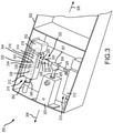
- FIG. 3 a perspective view of a lock mechanism 300 for a thrust reverser is illustrated, in accordance with various embodiments.
- the lock mechanism 300 is illustrated mounted to a frame 302.
- the frame 302 is connected to or made an integral part of a side beam, such as one of the opposing side beams 206 referred to in FIG. 2 .
- the lock mechanism 300 may include an actuator 303 configured to selectively translate a tee-handle 304 in a fore direction 306 and an aft direction 308.
- the fore direction 306 and the aft direction 308 are parallel to a central axis, such as the central axis A referred to in FIG. 2 .
- the tee-handle 304 may be coupled to a pair of blade assemblies 310 configured to slidably engage lock fittings extending from side portions of upper and lower reverser doors, such as, for example, the lock fittings 218 referred to in FIG. 2 .
- the blade assemblies 310 are urged in the aft direction 308 to engage the lock fittings and in the fore direction 306 to disengage the lock fittings. While the following disclosure employs the fore direction 306 and the aft direction 308 for purposes of description, it will be appreciated that the directions may be reversed by reversing the orientation of components with respect to the frame 302. Further, the disclosure may equally be read to employ terms such as first direction and second direction in describing the various embodiments disclosed herein, with the first and second directions including directions other than fore and aft.
- Each blade assembly 310 includes a blade housing 312 and a blade member 314 slidably disposed within the blade housing 312 to translate in the fore direction 306 and the aft direction 308.
- the blade member 314 includes a base portion 316 and a blade portion 318.
- the base portion 316 may be cylindrical in cross section and is configured to slidably translate within a corresponding cylindrically shaped hollow portion 320 disposed within the blade housing 312. While various embodiments are described having a base portion 316 that is cylindrically shaped and a cylindrically shaped hollow portion 320, other shapes are contemplated, such as triangular, square, polygonal and elliptical shapes, etc.
- each blade member 314 is coupled to the tee-handle 304 using a loose-joint coupling 322.
- the loose-joint coupling 322 includes a coupling member 324 having a bottom portion 326, a first side portion 328 and a second side portion 330.
- the first side portion 328 and the second side portion 330 are spaced a distance sufficient to receive an arm 332 of the tee-handle 304 between the two portions.
- the bottom portion 326 may extend between the first side portion 328 and the second side portion 330.
- the coupling member 324 may be configured to loosely receive the arm 332 of the tee-handle 304 and may include a clip member 329 in order to retain the arm 332 within the coupling member 324.
- the coupling member 324 or any component thereof, including one or more of the bottom portion 326, the first side portion 328 and the second side portion 330, is made integral with the blade member 314.
- the tee-handle 304 also includes a translating member 305 configured to translate in and out of the actuator 303 along the fore direction 306 and the aft direction 308 and the arm 332 is connected to the translating member 305 via a tee-coupling 307.
- the loose-joint coupling 322 enables the actuator 303 to urge the blade member 314 in the fore direction 306 and in the aft direction 308 by translation of the tee-handle 304 in the fore direction 306 and in the aft direction 308, respectively.
- an open end of the loose-joint coupling 322 - e.g., the open end opposite the bottom portion 326 of the coupling member 324 - decouples the blade member 314 from the tee-handle 304.
- a spring element 334 is employed to urge the blade member 314 in the aft direction 308 as the actuator 303 disengages from or otherwise allows the tee-handle 304 to freely translate in the aft direction 308.
- additional spring elements may be employed, either alone or in combination with the spring element 334.
- additional spring elements may, for example, be located in the actuator housing, as described below.
- the spring element 334 When allowed to translate, the spring element 334 provides a load to translate the tee-handle 304 in the aft direction 308 via the load placed against the blade member 314.
- the spring element 334 comprises a passive element such as a coil spring 336 disposed within the cylindrically shaped hollow portion 320 of the blade housing 312. A first end 338 of the coil spring 336 abuts an end portion 340 of the blade housing 312, while a second end 342 of the coil spring 336 abuts a fore end 344 of the base portion 316 of the blade member 314.
- the spring element 334, or coil spring 336 may be configured to apply a continuous load on the blade member 314, urging the blade member 314 in the aft direction 308.
- the above described configuration enables the blade member 314 to be urged in the fore direction 306 by operation of the actuator 303 translating the tee-handle 304 in the fore direction 306.
- the configuration also enables the blade member 314 to be urged in the aft direction 308 by the load applied to the blade member 314 by the spring element 334 or coil spring 336 upon release of the load in the fore direction 306 placed on the tee-handle 304 by the actuator 303.
- a passive element such as the coil spring 336
- other load producing systems such as active hydraulic systems or electro-mechanical systems are contemplated as providing the load on the blade member 314 in the fore direction 306, either continuously or on demand.
- the blade member 314, or the blade portion 318 of the blade member 314, is shaped or configured to be urged in the aft direction 308 in the case of a malfunction of an electronic or hydraulic system operating or controlling the lock mechanism 300.
- An angled surface of the blade portion 318 facilitates translational movement of the blade portion 318 with respect to a lock fitting once the lock fitting assumes an overstow position or a near overstow position.
- a proximity sensor 350 is disposed proximate the blade member 314 to detect the position of the blade member 314 - e.g., the translational position of the blade member 314 in both the fore direction 306 and the aft direction 308.
- the proximity sensor 350 may be configured to provide information to a controller whether the thrust reverser doors are locked to maintain a closed or stowed position or unlocked to maintain open or deployed position.
- the proximity sensor 350 may also be employed to provide information relating to partial or insufficient engagement of the blade member 314, such as occurs if the blade member 314 assumes a position insufficient to ensure the thrust reverser doors maintain a closed or stowed position.
- the blade member 314 or, more particularly, the blade portion 318 of the blade member 314 is urged in the aft direction 308 to engage a lock fitting, such as one of the lock fittings 218 referred to in FIG. 2 , thereby preventing the corresponding thrust reverser door from opening or deploying.
- a lock fitting such as one of the lock fittings 218 referred to in FIG. 2
- the blade member 314 or, more particularly, the blade portion 318 of the blade member 314 is urged in the fore direction 306 to disengage the lock fitting, thereby allowing the corresponding thrust reverser door to open or deploy.
- a cover 352 may be used to enclose the area where the blade portion 318 engages the lock fitting.
- a single lock mechanism 300 e.g. , a first or port lock mechanism
- the lock mechanism 210 referred to in FIGS. 2A and 2B is illustrated as positioned on the port side beam, it will be appreciated that a second lock mechanism may be positioned on the starboard side beam in similar fashion using the same or similar componentry and principles of operation described above and below.
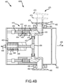
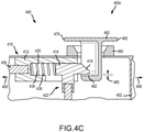
- FIGS. 4A , 4B and 4C side views of a lock mechanism 400 in an unlocked state 400a, a locked state 400b and an overstow state 400c are illustrated, respectively, to describe the various components and operation thereof.
- the lock mechanism 400 includes many of the components above described with similar operational features.
- the lock mechanism 400 is illustrated mounted to a frame 402.
- the frame 402 is connected to or made an integral part of a side beam, such as one of the opposing side beams 206 referred to in FIG. 2 .
- the lock mechanism 400 may include an actuator 403 configured to selectively translate a tee-handle 404 in a fore direction 406 and an aft direction 408.
- the fore direction 406 and the aft direction 408 are parallel to a central axis, such as the central axis A referred to in FIG. 2 .
- the tee-handle 404 may be coupled to a pair of blade assemblies 410 configured to slidably engage lock fittings 460 (see FIG. 4C ) extending from side portions of upper and lower reverser doors.
- the blade assemblies 410 are urged in the aft direction 408 to engage the lock fittings 460 and in the fore direction 406 to disengage the lock fittings 460, as illustrated in FIGS 4B and 4A , respectively.
- each blade assembly 410 includes a blade housing 412 and a blade member 414 slidably disposed within the blade housing 412 to translate in the fore direction 406 and the aft direction 408.
- the blade member 414 includes a base portion 416 and a blade portion 418.
- the base portion 416 may be cylindrical in cross section and configured to slidably translate within a corresponding cylindrically shaped hollow portion 420 disposed within the blade housing 412.
- each blade member 414 is coupled to the tee-handle 404 using a loose-joint coupling 422.
- the loose-joint coupling 422 includes the same constructions, configurations, variations and features of the loose-joint 322 coupling described above with respect to FIG. 3 and, therefore, are not repeated.
- a spring element 434 may be employed to urge the blade member 414 in the aft direction 408 as the actuator 403 disengages from or otherwise allows the tee-handle 404 to translate in the aft direction 408.
- the spring element 434 provides a load to translate the tee-handle 404 in the aft direction 408 via the load placed against the blade member 414.
- the spring element 434 may comprise passive or active elements or, in various embodiments, a coil spring 436 disposed within the cylindrically shaped hollow portion 420 of the blade housing 412.
- a proximity sensor 450 is disposed proximate the blade member 414 to detect the position of the blade member 414 - e.g., the translational position of the blade member 414 in both the fore direction 406 and the aft direction 408.
- the proximity sensor 450 may be configured to provide information to a controller whether the thrust reverser doors are locked to maintain a closed or stowed position or unlocked to maintain open or deployed position.
- the actuator 403 includes one or more actuator spring elements 444 that may also be employed to urge the blade member 414 in the aft direction 408 as the actuator 403 disengages from or otherwise allows the tee-handle 404 to translate in the aft direction 408.
- the actuator spring element 444 provides a load to translate the tee-handle 404 in the aft direction 408 via a load placed against a piston member 448 in the actuator 403.
- the actuator spring element 444 may comprise passive or active elements or, in various embodiments, a coil spring 446 disposed within the actuator 403.
- the coil spring 446 has a first end disposed against the piston member 448 and a second end disposed against a base of the actuator 403 or frame 402. While spring elements are described in both the blade housing 412 and the actuator 403, it will be appreciated that either or both may be employed, according to various embodiments.
- a kinematic depiction 470 of a lock fitting 460 entering the lock mechanism 400 as an upper door of a thrust reverser closes or is stowed is illustrated.
- the kinematic depiction 470 illustrates a first state 472, a second state 474 and a final, locked state 476 of the lock fitting 460 with respect to the lock mechanism 400.
- the lock fitting 460 is urged downward into the lock mechanism 400, displaying a slight arc due to the upper door being connected to the thrust reverser by a pivot aft of the lock mechanism.
- the lock fitting 460 While the lock fitting 460 is extending inward of the lock mechanism 400, the blade member 414 is translated in the fore direction 406 by the actuator 403 as described above.
- the lock fitting 460 will eventually reach an overstow position 478, as illustrated in FIG. 4C .
- the overstow position 478 provides a gap 480 between the blade portion 418 of the blade member 414 and an engagement surface 482 of the lock fitting 460.
- the actuator urges the tee-handle 404 to translate freely in the aft direction, which allows the spring element 434 to urge the blade portion 418 of the blade member 414 to translate into position adjacent the engagement surface 482 of the lock fitting 460.
- the lock fitting 460 then reverses direction a slight distance to assume the final, locked state 476 as illustrated in FIG. 4B .
- a stop member 490 is sized and positioned to guide the lock fitting 460 into a proper location while the lock fitting 460 is traversing an arc during opening or closing of the thrust reverser doors.
- the stop member 490 may also be employed to reduce or minimize any misalignment of the lock fitting 460 due to defection of the thrust reverser doors during flight.
- the stop member 490 may also be employed to prevent the lock fitting 460 from over extending into the lock mechanism 400 by engaging an undersurface 492 of the lock fitting 460 at a predetermined extension of the lock fitting 460 into the lock mechanism 400.
- the lock fitting 460 When deploying the thrust reverser, the process described above is reversed.
- the lock fitting 460 is first urged into the overstow position 478, which removes any load between the blade portion 418 and the engagement surface 482 of the lock fitting 460.
- the actuator 403 then urges the tee-handle 404 in the fore direction 406, which in turn urges the blade portion 418 of the blade member 414 toward the fore direction 406 and away from the engagement surface 482 of the lock fitting 460.
- the lock fitting 460 then extends outward of the lock mechanism 400, following the reverse of the kinematic depiction 470 illustrated in FIG. 4B .
- the actuator 403 will maintain the blade member 414 in the unlocked state until the reverser door is returned to a stowed state.
- the foregoing steps of locking and unlocking the lock mechanism 400 may be carried out under the control of an engine control unit, which may be configured to sequence various aircraft systems during a landing or during flight to ensure engagement of the blade portion 418 and the lock fitting 460 when required during flight and non-engagement during landing.
- the above disclosure provides a robust and efficient load path between a lock fitting of a thrust reverser door and a blade member and its associated housing of a lock mechanism.
- the blade size and engagement length - e.g., the contact surface between the blade portion of a blade member and the engagement surface of a lock fitting - may be optimized for load, providing efficient and capable load paths within a small space envelope.
- the disclosure also allows decoupling of the loads between the blade member and its associated housing and the actuator through use of loose joints or fittings between the blade member and the actuator.
- the disclosure also provides a locking mechanism configured to disengage the blade members from the lock fittings with minimal overstow clearance, if required.
- the disclosure set forth above and below is sequenced via an electronic engine controller to facilitate engagement of the blade members and the lock fittings under minimal load between the two.
Landscapes
- Engineering & Computer Science (AREA)
- Chemical & Material Sciences (AREA)
- Combustion & Propulsion (AREA)
- Mechanical Engineering (AREA)
- General Engineering & Computer Science (AREA)
- Lock And Its Accessories (AREA)
Description
- The present disclosure relates generally to aircraft thrust reversers used with gas turbine engines and, more particularly, to locking mechanisms used with pivot door thrust reversers.
- Turbofan gas turbine engines are known to include a fan section that produces a bypass airflow for providing the majority of engine propulsion and a core engine section through which a core airflow is compressed, mixed with fuel, combusted and expanded through a turbine to drive the fan section. In a mixed flow turbofan engine, the cool bypass airflow is ducted between a surrounding nacelle and an outer casing of the core engine section and mixed with a hot exhaust stream from the core engine section prior to discharge from the engine nozzle in a combined or mixed exhaust stream. The surrounding nacelle may include thrust reversers capable of redirecting the bypass airflow from the rearward direction to, at least partially, a forward direction thus producing a rearward thrust that may serve to decelerate the forward motion of an aircraft and thereby assist braking the aircraft upon landing. Pivot door thrust reversers may be used with turbofan gas turbine engines for aircraft, including for corporate or business jets. A locking mechanism for a pivot door thrust reverser is disclosed herein.
-
US 2014/245716 A1 andUS 5 344 197 A disclose prior art systems. - A thrust reverser comprising a pivot door and a lock mechanism is disclosed according to claim 1.
- Various embodiments of the invention are defined by the dependent claims.
- The subject matter of the present disclosure is particularly pointed out and distinctly claimed in the concluding portion of the specification. A more complete understanding of the present disclosure, however, may best be obtained by referring to the following detailed description and claims in connection with the following drawings. While the drawings illustrate various embodiments employing the principles described herein, the drawings do not limit the scope of the claims.
-
FIG. 1 is a schematic view of a gas turbine engine, in accordance with various embodiments; -
FIGS. 2A and2B provide schematic views of a stowed thrust reverser for a gas turbine engine and a deployed thrust reverser for a gas turbine engine, respectively, according to various embodiments; -
FIG. 3 is a perspective view of a thrust reverser door lock mechanism, according to various embodiments; and -
FIGS. 4A ,4B and4C are side views of a thrust reverser door lock mechanism in, respectively, an unlocked state, a locked state and an overstow state. - As used herein, a first component that is "radially outward" of a second component means that the first component is positioned at a greater distance away from a common axis than the second component. A first component that is "radially inward" of a second component means that the first component is positioned closer to the common axis than the second component. In the case of components that rotate circumferentially about a common axis, a first component that is radially inward of a second component rotates through a circumferentially shorter path than the second component. As used herein, "distal" refers to a direction outward or, generally, away from a reference component. As used herein, "proximal" or "proximate" refer to a direction inward or, generally, towards a reference component.
- Referring to the drawings,
FIG. 1 schematically illustrates agas turbine engine 100 of the turbofan variety. Thegas turbine engine 100 generally includes afan section 102 and acore engine section 104, which includes acompressor section 106, acombustor section 108 and aturbine section 110. Thefan section 102 drives air along a bypass flow path B in abypass duct 112 defined within a radiallyinner surface 115 of anacelle 114 and anouter casing 116 of thecore engine section 104, while thecompressor section 106 drives air along a core flow path C of thecore engine section 104 for compression and communication into thecombustor section 108 and then expansion through theturbine section 110. - The
core engine section 104 may generally include a low speed spool and a high speed spool mounted for rotation about a central longitudinal axis A. The low speed spool generally includes an inner shaft that interconnects afan 118 within thefan section 102, a low pressure compressor within thecompressor section 106 and a low pressure turbine within theturbine section 110. The inner shaft may be connected to thefan 118 through a speed change mechanism or gear box to drive thefan 118 at a lower rotational speed than the rotational speed of the low speed spool. The high speed spool generally includes an outer shaft that interconnects a high pressure compressor within thecompressor section 106 and a high pressure turbine within theturbine section 110. A combustor is arranged in thecombustor section 108 between the high pressure compressor and the high pressure turbine. The air passing through the bypass flow path B mixes with the combustion gases exiting the core flow path C in amixing section 122 positioned downstream of thecore engine section 104 prior to discharge as a mixedexhaust stream 120, which provides the thrust achieved by thegas turbine engine 100. - A
thrust reverser 130 is mounted to the aft end of thegas turbine engine 100. Thethrust reverser 130 includes a generallyannular exhaust duct 132, which defines an outer boundary for discharging the mixedexhaust stream 120 when the thrust reverser 130 assumes a closed, stowed or retracted position, as illustrated inFIG. 1 . The thrust reverser 130 further includes anupper reverser door 134, alower reverser door 136 and a pair ofopposing side beams 138, which may house actuator componentry and connecting members used to open and close theupper reverser door 134 andlower reverser door 136. As discussed below, thrust reversal is affected by opening theupper reverser door 134 and thelower reverser door 136 to direct all or a portion of the mixedexhaust stream 120 in a direction having an upstream component relative to the central longitudinal axis A of thegas turbine engine 100. The momentum of the upstream component of the mixedexhaust stream 120 provides the reverse thrust used to decelerate an aircraft upon landing. Disclosed below is a locking mechanism used to secure upper and lower doors of a thrust reverser, according to various embodiments. - Referring now to
FIGS. 2A and2B , in accordance with various embodiments, a side view of athrust reverser 200a is illustrated in a closed, stowed or retracted position and a perspective view of thethrust reverser 200b is illustrated in an open or a deployed position, respectively. The thrust reverser 200 (referring to both 200a and 200b) includes anupper reverser door 202, alower reverser door 204, a pair of opposing side beams 206 (only one is shown) and anexhaust duct 208. The pair ofopposing side beams 206 may provide a frame or structural support for operating the thrust reverser between deployed and retracted positions. In various embodiments, alock mechanism 210 may be secured to one or both of theopposing side beams 206. As will be described in further detail below, thelock mechanism 210 may include anactuator 212 configured to selectively translate a tee-handle 214 in afore direction 230 and anaft direction 232 with respect to a central axis A extending through the thrust reverser 200. The tee-handle 214 is coupled to a pair ofblade assemblies 216 that are configured to slidably engagelock fittings 218 that extend from side portions of theupper reverser door 202 and thelower reverser door 204 toward theblade assemblies 216. In various embodiments, theblade assemblies 216 are urged in theaft direction 232 to engage thelock fittings 218 and in thefore direction 230 to disengage thelock fittings 218. Anupper door actuator 220 is configured to open and close theupper reverser door 202 and alower door actuator 224 is configured to open and close thelower reverser door 204. In various embodiments, theupper door actuator 220 has afirst end 226 pivotally connected to an upper portion of abulkhead 228 and an aft end (hidden) pivotally connected to an inner surface of theupper reverser door 202. Thelower door actuator 224 may be similarly configured at the lower portion of the thrust reverser 200. - Referring now to
FIG. 3 , a perspective view of alock mechanism 300 for a thrust reverser is illustrated, in accordance with various embodiments. Thelock mechanism 300 is illustrated mounted to aframe 302. In various embodiments, theframe 302 is connected to or made an integral part of a side beam, such as one of theopposing side beams 206 referred to inFIG. 2 . Thelock mechanism 300 may include anactuator 303 configured to selectively translate a tee-handle 304 in afore direction 306 and anaft direction 308. In various embodiments, thefore direction 306 and theaft direction 308 are parallel to a central axis, such as the central axis A referred to inFIG. 2 . The tee-handle 304 may be coupled to a pair ofblade assemblies 310 configured to slidably engage lock fittings extending from side portions of upper and lower reverser doors, such as, for example, thelock fittings 218 referred to inFIG. 2 . In various embodiments, theblade assemblies 310 are urged in theaft direction 308 to engage the lock fittings and in thefore direction 306 to disengage the lock fittings. While the following disclosure employs thefore direction 306 and theaft direction 308 for purposes of description, it will be appreciated that the directions may be reversed by reversing the orientation of components with respect to theframe 302. Further, the disclosure may equally be read to employ terms such as first direction and second direction in describing the various embodiments disclosed herein, with the first and second directions including directions other than fore and aft. - Each
blade assembly 310 includes ablade housing 312 and ablade member 314 slidably disposed within theblade housing 312 to translate in thefore direction 306 and theaft direction 308. Theblade member 314 includes abase portion 316 and ablade portion 318. Thebase portion 316 may be cylindrical in cross section and is configured to slidably translate within a corresponding cylindrically shapedhollow portion 320 disposed within theblade housing 312. While various embodiments are described having abase portion 316 that is cylindrically shaped and a cylindrically shapedhollow portion 320, other shapes are contemplated, such as triangular, square, polygonal and elliptical shapes, etc. - In various embodiments, each
blade member 314 is coupled to the tee-handle 304 using a loose-joint coupling 322. The loose-joint coupling 322 includes acoupling member 324 having abottom portion 326, afirst side portion 328 and asecond side portion 330. Thefirst side portion 328 and thesecond side portion 330 are spaced a distance sufficient to receive anarm 332 of the tee-handle 304 between the two portions. Thebottom portion 326 may extend between thefirst side portion 328 and thesecond side portion 330. Thecoupling member 324 may be configured to loosely receive thearm 332 of the tee-handle 304 and may include aclip member 329 in order to retain thearm 332 within thecoupling member 324. In various embodiments, thecoupling member 324 or any component thereof, including one or more of thebottom portion 326, thefirst side portion 328 and thesecond side portion 330, is made integral with theblade member 314. The tee-handle 304 also includes a translatingmember 305 configured to translate in and out of theactuator 303 along thefore direction 306 and theaft direction 308 and thearm 332 is connected to the translatingmember 305 via a tee-coupling 307. - In various embodiments, the loose-
joint coupling 322 enables theactuator 303 to urge theblade member 314 in thefore direction 306 and in theaft direction 308 by translation of the tee-handle 304 in thefore direction 306 and in theaft direction 308, respectively. Conversely, an open end of the loose-joint coupling 322 - e.g., the open end opposite thebottom portion 326 of the coupling member 324 - decouples theblade member 314 from the tee-handle 304. - A
spring element 334 is employed to urge theblade member 314 in theaft direction 308 as theactuator 303 disengages from or otherwise allows the tee-handle 304 to freely translate in theaft direction 308. As described below with reference toFIGS. 4A and4B , additional spring elements may be employed, either alone or in combination with thespring element 334. Such additional spring elements may, for example, be located in the actuator housing, as described below. When allowed to translate, thespring element 334 provides a load to translate the tee-handle 304 in theaft direction 308 via the load placed against theblade member 314. Thespring element 334 comprises a passive element such as acoil spring 336 disposed within the cylindrically shapedhollow portion 320 of theblade housing 312. Afirst end 338 of thecoil spring 336 abuts anend portion 340 of theblade housing 312, while asecond end 342 of thecoil spring 336 abuts afore end 344 of thebase portion 316 of theblade member 314. In various embodiments, thespring element 334, orcoil spring 336, may be configured to apply a continuous load on theblade member 314, urging theblade member 314 in theaft direction 308. - The above described configuration enables the
blade member 314 to be urged in thefore direction 306 by operation of theactuator 303 translating the tee-handle 304 in thefore direction 306. The configuration also enables theblade member 314 to be urged in theaft direction 308 by the load applied to theblade member 314 by thespring element 334 orcoil spring 336 upon release of the load in thefore direction 306 placed on the tee-handle 304 by theactuator 303. While various embodiments are described employing a passive element, such as thecoil spring 336, as thespring element 334, other load producing systems, such as active hydraulic systems or electro-mechanical systems are contemplated as providing the load on theblade member 314 in thefore direction 306, either continuously or on demand. In various embodiments, theblade member 314, or theblade portion 318 of theblade member 314, is shaped or configured to be urged in theaft direction 308 in the case of a malfunction of an electronic or hydraulic system operating or controlling thelock mechanism 300. An angled surface of theblade portion 318, for example, facilitates translational movement of theblade portion 318 with respect to a lock fitting once the lock fitting assumes an overstow position or a near overstow position. - In various embodiments, a
proximity sensor 350 is disposed proximate theblade member 314 to detect the position of the blade member 314 - e.g., the translational position of theblade member 314 in both thefore direction 306 and theaft direction 308. Theproximity sensor 350 may be configured to provide information to a controller whether the thrust reverser doors are locked to maintain a closed or stowed position or unlocked to maintain open or deployed position. Theproximity sensor 350 may also be employed to provide information relating to partial or insufficient engagement of theblade member 314, such as occurs if theblade member 314 assumes a position insufficient to ensure the thrust reverser doors maintain a closed or stowed position. As described further below, when the thrust reverser doors are locked to maintain a closed or stowed position, theblade member 314 or, more particularly, theblade portion 318 of theblade member 314, is urged in theaft direction 308 to engage a lock fitting, such as one of thelock fittings 218 referred to inFIG. 2 , thereby preventing the corresponding thrust reverser door from opening or deploying. Similarly, when the thrust reverser doors are unlocked to allow an open or deployed position to occur, theblade member 314 or, more particularly, theblade portion 318 of theblade member 314, is urged in thefore direction 306 to disengage the lock fitting, thereby allowing the corresponding thrust reverser door to open or deploy. In various embodiments, acover 352 may be used to enclose the area where theblade portion 318 engages the lock fitting. - While the above description focuses on a single blade member 314 (e.g., a first or upper blade member) and its associated components and connections, the same description applies to a second or lower blade member and its associated components and connections, as illustrated in
FIG. 3 . Similarly, while the above description focuses on a single lock mechanism 300 (e.g., a first or port lock mechanism), the same description applies to a second or starboard lock mechanism. For example, while thelock mechanism 210 referred to inFIGS. 2A and2B is illustrated as positioned on the port side beam, it will be appreciated that a second lock mechanism may be positioned on the starboard side beam in similar fashion using the same or similar componentry and principles of operation described above and below. - Referring now to
FIGS. 4A ,4B and4C , side views of alock mechanism 400 in anunlocked state 400a, a lockedstate 400b and anoverstow state 400c are illustrated, respectively, to describe the various components and operation thereof. Using like numerals to indicate like components, thelock mechanism 400 includes many of the components above described with similar operational features. In various embodiments, thelock mechanism 400 is illustrated mounted to aframe 402. In various embodiments, theframe 402 is connected to or made an integral part of a side beam, such as one of the opposing side beams 206 referred to inFIG. 2 . Thelock mechanism 400 may include anactuator 403 configured to selectively translate a tee-handle 404 in afore direction 406 and anaft direction 408. In various embodiments, thefore direction 406 and theaft direction 408 are parallel to a central axis, such as the central axis A referred to inFIG. 2 . The tee-handle 404 may be coupled to a pair ofblade assemblies 410 configured to slidably engage lock fittings 460 (seeFIG. 4C ) extending from side portions of upper and lower reverser doors. In various embodiments, theblade assemblies 410 are urged in theaft direction 408 to engage thelock fittings 460 and in thefore direction 406 to disengage thelock fittings 460, as illustrated inFIGS 4B and4A , respectively. - In various embodiments, each
blade assembly 410 includes ablade housing 412 and ablade member 414 slidably disposed within theblade housing 412 to translate in thefore direction 406 and theaft direction 408. In various embodiments, theblade member 414 includes abase portion 416 and ablade portion 418. Thebase portion 416 may be cylindrical in cross section and configured to slidably translate within a corresponding cylindrically shapedhollow portion 420 disposed within theblade housing 412. In various embodiments, eachblade member 414 is coupled to the tee-handle 404 using a loose-joint coupling 422. In various embodiments, the loose-joint coupling 422 includes the same constructions, configurations, variations and features of the loose-joint 322 coupling described above with respect toFIG. 3 and, therefore, are not repeated. - As described above, a
spring element 434 may be employed to urge theblade member 414 in theaft direction 408 as theactuator 403 disengages from or otherwise allows the tee-handle 404 to translate in theaft direction 408. When allowed to translate, thespring element 434 provides a load to translate the tee-handle 404 in theaft direction 408 via the load placed against theblade member 414. As described above, thespring element 434 may comprise passive or active elements or, in various embodiments, acoil spring 436 disposed within the cylindrically shapedhollow portion 420 of theblade housing 412. In various embodiments, aproximity sensor 450 is disposed proximate theblade member 414 to detect the position of the blade member 414 - e.g., the translational position of theblade member 414 in both thefore direction 406 and theaft direction 408. Theproximity sensor 450 may be configured to provide information to a controller whether the thrust reverser doors are locked to maintain a closed or stowed position or unlocked to maintain open or deployed position. - In various embodiments, the
actuator 403 includes one or moreactuator spring elements 444 that may also be employed to urge theblade member 414 in theaft direction 408 as theactuator 403 disengages from or otherwise allows the tee-handle 404 to translate in theaft direction 408. When allowed to translate, theactuator spring element 444 provides a load to translate the tee-handle 404 in theaft direction 408 via a load placed against apiston member 448 in theactuator 403. Theactuator spring element 444 may comprise passive or active elements or, in various embodiments, acoil spring 446 disposed within theactuator 403. In various embodiments, thecoil spring 446 has a first end disposed against thepiston member 448 and a second end disposed against a base of theactuator 403 orframe 402. While spring elements are described in both theblade housing 412 and theactuator 403, it will be appreciated that either or both may be employed, according to various embodiments. - Referring now to
FIG. 4B , akinematic depiction 470 of a lock fitting 460 entering thelock mechanism 400 as an upper door of a thrust reverser closes or is stowed is illustrated. Thekinematic depiction 470 illustrates afirst state 472, asecond state 474 and a final, lockedstate 476 of the lock fitting 460 with respect to thelock mechanism 400. As illustrated, the lock fitting 460 is urged downward into thelock mechanism 400, displaying a slight arc due to the upper door being connected to the thrust reverser by a pivot aft of the lock mechanism. While the lock fitting 460 is extending inward of thelock mechanism 400, theblade member 414 is translated in thefore direction 406 by theactuator 403 as described above. The lock fitting 460 will eventually reach anoverstow position 478, as illustrated inFIG. 4C . Theoverstow position 478 provides agap 480 between theblade portion 418 of theblade member 414 and anengagement surface 482 of the lock fitting 460. While the lock fitting 460 is in theoverstow position 478, the actuator urges the tee-handle 404 to translate freely in the aft direction, which allows thespring element 434 to urge theblade portion 418 of theblade member 414 to translate into position adjacent theengagement surface 482 of the lock fitting 460. The lock fitting 460 then reverses direction a slight distance to assume the final, lockedstate 476 as illustrated inFIG. 4B . In various embodiments, astop member 490 is sized and positioned to guide the lock fitting 460 into a proper location while the lock fitting 460 is traversing an arc during opening or closing of the thrust reverser doors. Thestop member 490 may also be employed to reduce or minimize any misalignment of the lock fitting 460 due to defection of the thrust reverser doors during flight. Thestop member 490 may also be employed to prevent the lock fitting 460 from over extending into thelock mechanism 400 by engaging anundersurface 492 of the lock fitting 460 at a predetermined extension of the lock fitting 460 into thelock mechanism 400. - When deploying the thrust reverser, the process described above is reversed. The lock fitting 460 is first urged into the
overstow position 478, which removes any load between theblade portion 418 and theengagement surface 482 of the lock fitting 460. Theactuator 403 then urges the tee-handle 404 in thefore direction 406, which in turn urges theblade portion 418 of theblade member 414 toward thefore direction 406 and away from theengagement surface 482 of the lock fitting 460. The lock fitting 460 then extends outward of thelock mechanism 400, following the reverse of thekinematic depiction 470 illustrated inFIG. 4B . In various embodiments, theactuator 403 will maintain theblade member 414 in the unlocked state until the reverser door is returned to a stowed state. The foregoing steps of locking and unlocking thelock mechanism 400 may be carried out under the control of an engine control unit, which may be configured to sequence various aircraft systems during a landing or during flight to ensure engagement of theblade portion 418 and the lock fitting 460 when required during flight and non-engagement during landing. - The above disclosure provides a robust and efficient load path between a lock fitting of a thrust reverser door and a blade member and its associated housing of a lock mechanism. The blade size and engagement length - e.g., the contact surface between the blade portion of a blade member and the engagement surface of a lock fitting - may be optimized for load, providing efficient and capable load paths within a small space envelope. The disclosure also allows decoupling of the loads between the blade member and its associated housing and the actuator through use of loose joints or fittings between the blade member and the actuator. The disclosure also provides a locking mechanism configured to disengage the blade members from the lock fittings with minimal overstow clearance, if required. In various embodiments, the disclosure set forth above and below is sequenced via an electronic engine controller to facilitate engagement of the blade members and the lock fittings under minimal load between the two.
Claims (4)
- A thrust reverser (130, 200) comprising a pivot door (134, 136, 202, 204) and a lock mechanism (210, 300, 400), the lock mechanism (210, 300, 400) comprising:a frame portion (302, 402) of the thrust reverser (130, 200), the frame portion (302, 402) defining a first direction (230, 306, 406) and a second direction (232, 308, 408) with respect to the thrust reverser (130, 200);a blade housing (312, 412) connected to the frame portion (302, 402);a blade member (314, 414) slidably disposed within the blade housing (312, 412) and configured to translate with respect to the first direction (230, 306, 406) and the second direction (232, 308, 408), the blade member (314, 414) configured to engage a lock fitting (218, 460) of the pivot door (134, 136, 202, 204);an actuator (212, 303, 403) configured to translate the blade member (314, 414) in the first direction (230, 306, 406);a spring element (334, 434, 444) configured to urge the blade member (314, 414) in the second direction (232, 308, 408); anda loose-joint coupling (322, 422) configured to connect the actuator (212, 303, 403) to the blade member (314, 414), wherein the loose-joint coupling (322, 422) comprises a first or coupling member (324) made integral with the blade member (314, 414) and configured to translate the blade member (314, 414) in the first direction (230, 306, 406) in response to the actuator (212, 303, 403), and the first or coupling member (324) includes a bottom portion (326), a first side portion (328) and a second side portion (330),wherein the actuator (212, 303, 403) includes a translating member (305) configured to translate in the first direction (230, 306, 406) and the second direction (232, 308, 408) and an arm (332) connecting the translating member (305) to the blade member (314, 414),wherein the loose-joint coupling (322, 422) is positioned between the arm (332) and the blade member (314, 414),wherein the blade member (314, 414) comprises a base portion (316, 416) and the blade housing (312, 412) comprises a hollow portion (320, 420) configured for translational movement of the base portion (316, 416) within the blade housing (312, 412), andwherein the spring element (334, 434, 444) is a coil spring (336, 436) having a first end (338) configured to abut the blade housing (312, 412) and a second end (342) configured to abut the blade member (314, 414).
- The thrust reverser (130, 200) of claim 1, further comprising a second coil spring having a first end configured to abut a base of the actuator (212, 303, 403) and a second end configured to abut a piston (448) disposed within the actuator (212, 303, 403) and connected to the translating member (305).
- The thrust reverser (130, 200) of claim 1 or 2, wherein the blade member (314, 414) comprises a blade portion (318, 418) configured to engage the lock fitting (218, 460) of the pivot door (134, 136, 202, 204).
- The thrust reverser (130, 200) of claim 1, 2, or 3, wherein the first direction (230, 306, 406) is a fore direction with respect to the thrust reverser (130, 200) and the second direction (232, 308, 408) is an aft direction with respect to the thrust reverser (130, 200).
Applications Claiming Priority (2)
| Application Number | Priority Date | Filing Date | Title |
|---|---|---|---|
| US201762575965P | 2017-10-23 | 2017-10-23 | |
| US16/029,387 US10907577B2 (en) | 2017-10-23 | 2018-07-06 | Translating lock for pivot door thrust reverser |
Publications (2)
| Publication Number | Publication Date |
|---|---|
| EP3517766A1 EP3517766A1 (en) | 2019-07-31 |
| EP3517766B1 true EP3517766B1 (en) | 2022-03-23 |
Family
ID=66170486
Family Applications (1)
| Application Number | Title | Priority Date | Filing Date |
|---|---|---|---|
| EP18202158.4A Active EP3517766B1 (en) | 2017-10-23 | 2018-10-23 | Translating lock for pivot door thrust reverser |
Country Status (4)
| Country | Link |
|---|---|
| US (1) | US10907577B2 (en) |
| EP (1) | EP3517766B1 (en) |
| CN (1) | CN109695513B (en) |
| CA (1) | CA3016002A1 (en) |
Families Citing this family (6)
| Publication number | Priority date | Publication date | Assignee | Title |
|---|---|---|---|---|
| FR3092874B1 (en) * | 2019-02-14 | 2021-01-22 | Safran Nacelles | Door closing system for thrust reverser of an aircraft nacelle |
| FR3099802B1 (en) * | 2019-08-07 | 2021-12-17 | Safran Nacelles | Aircraft nacelle thrust reverser door position sensor |
| US11326554B2 (en) * | 2020-07-02 | 2022-05-10 | Woodward, Inc. | Hydraulic baulking sync lock |
| EP4177457A1 (en) * | 2021-11-03 | 2023-05-10 | Goodrich Actuation Systems Limited | Lock position sensing |
| CN116733772A (en) * | 2022-03-02 | 2023-09-12 | 杭州老板电器股份有限公司 | Motor impeller and fan |
| US12515781B2 (en) | 2022-07-29 | 2026-01-06 | Textron Innovations Inc. | Retractable door pins for aircraft door |
Family Cites Families (24)
| Publication number | Priority date | Publication date | Assignee | Title |
|---|---|---|---|---|
| BE466778A (en) * | 1945-07-21 | 1900-01-01 | ||
| BE756228R (en) * | 1970-03-02 | 1971-03-01 | Gen Electric | |
| FR2500537B1 (en) * | 1981-02-24 | 1985-07-05 | Astech | SAFETY DEVICE FOR A DRIVE INVERTER ASSOCIATED WITH AN AIRCRAFT REACTION ENGINE |
| US4790495A (en) * | 1984-12-06 | 1988-12-13 | Grumman Aerospace Corporation | Cascade thrust reverser |
| FR2683254B1 (en) * | 1991-11-06 | 1994-01-07 | Messier Bugatti | SECURITY LOCKING DEVICE WITH TILTING HOOK. |
| DE69512616T2 (en) * | 1994-12-15 | 2000-06-29 | The Dee Howard Co., San Antonio | Thrust reverser with longitudinally movable flaps |
| US5826823A (en) | 1996-02-07 | 1998-10-27 | Rohr, Inc. | Actuator and safety lock system for pivoting door thrust reverser for aircraft jet engine |
| US6260801B1 (en) * | 1999-09-17 | 2001-07-17 | The Nordam Group, Inc. | Swing pivot thrust reverser |
| US6293495B1 (en) * | 1999-12-08 | 2001-09-25 | Rohr, Inc. | Pivoting door thrust reverser system for turbofan aircraft jet engine |
| US6487845B1 (en) | 2001-06-08 | 2002-12-03 | The Nordam Group, Inc. | Pivot fairing thrust reverser |
| US6684623B2 (en) * | 2002-02-27 | 2004-02-03 | Honeywell International, Inc. | Gearless electric thrust reverser actuators and actuation system incorporating same |
| CA2486172C (en) * | 2002-05-21 | 2010-11-09 | The Nordam Group, Inc. | Variable area thrust reverser nozzle |
| US6935097B2 (en) * | 2003-04-17 | 2005-08-30 | Honeywell International, Inc. | Lock assembly that inhibits thrust reverser movement at or near the stowed position |
| US20050001095A1 (en) * | 2003-05-05 | 2005-01-06 | Christensen Donald J. | Self-aligning thrust reverser system lock assembly |
| US7946105B2 (en) * | 2006-11-02 | 2011-05-24 | Honeywell International Inc. | Bi-directional locking ring assembly for aircraft thrust reverser manual drive unit |
| US8628128B2 (en) * | 2009-04-21 | 2014-01-14 | Spirit Aerosystems, Inc. | Tertiary lock for pivot door thrust reverser |
| FR2982324B1 (en) * | 2011-11-09 | 2013-11-15 | Aircelle Sa | PUSH-IN REVERSER WITH TWIN DOORS |
| US9188081B2 (en) * | 2012-04-10 | 2015-11-17 | Honeywell International Inc. | Thrust reverser actuator with primary lock |
| US9109536B2 (en) * | 2013-03-14 | 2015-08-18 | Woodward Hrt, Inc. | Engine thrust reverser lock |
| EP3027876A1 (en) * | 2013-07-30 | 2016-06-08 | General Electric Company | Thrust reverser system with translating-rotating hinge assembly |
| US9611808B2 (en) * | 2014-03-21 | 2017-04-04 | Rohr, Inc. | Blocker door lock mechanism of a thrust reverser for a turbofan engine |
| FR3019590B1 (en) | 2014-04-02 | 2020-05-29 | Safran Nacelles | LOCKING SYSTEM FOR A PUSH-INVERTER WITH DOORS, COMPRISING LATCHES FOR AN INTERMEDIATE OPENING POSITION |
| US10041443B2 (en) * | 2015-06-09 | 2018-08-07 | The Boeing Company | Thrust reverser apparatus and method |
| US10415504B2 (en) * | 2016-02-09 | 2019-09-17 | Honeywell International Inc. | Translating cowl thrust reverser system with over-stow unlocking capability |
-
2018
- 2018-07-06 US US16/029,387 patent/US10907577B2/en active Active
- 2018-08-29 CA CA3016002A patent/CA3016002A1/en active Pending
- 2018-10-23 EP EP18202158.4A patent/EP3517766B1/en active Active
- 2018-10-23 CN CN201811236282.XA patent/CN109695513B/en active Active
Non-Patent Citations (1)
| Title |
|---|
| None * |
Also Published As
| Publication number | Publication date |
|---|---|
| EP3517766A1 (en) | 2019-07-31 |
| US20190120173A1 (en) | 2019-04-25 |
| CN109695513A (en) | 2019-04-30 |
| BR102018068394A2 (en) | 2019-08-13 |
| CA3016002A1 (en) | 2019-04-23 |
| US10907577B2 (en) | 2021-02-02 |
| CN109695513B (en) | 2022-09-09 |
Similar Documents
| Publication | Publication Date | Title |
|---|---|---|
| EP3517766B1 (en) | Translating lock for pivot door thrust reverser | |
| US7559507B2 (en) | Thrust reversers including locking assemblies for inhibiting deflection | |
| US11060481B2 (en) | Translating cowl thrust reverser system with over-stow unlocking capability | |
| US11236700B2 (en) | Three actuator cascade type thrust reverser actuation system | |
| EP3193002B1 (en) | Translating cascade hidden blocker door thrust reverser | |
| US11927150B2 (en) | Drive system for translating structure | |
| US10167815B2 (en) | Thrust reverser of a turbofan pod comprising a single control for movable cowlings and a variable nozzle | |
| EP3943737B1 (en) | Hidden door thrust reverser system for an aircraft propulsion system | |
| EP3477085B1 (en) | Hinge mechanism for pivot door thrust reversers | |
| US11566585B2 (en) | Synchronization mechanism for pivot door thrust reversers | |
| US20170138304A1 (en) | Drag link assembly for a thrust reverser | |
| EP3772581B1 (en) | Drive system for translating structure | |
| US12372046B2 (en) | Thrust reverser with blocker door lock | |
| US10641208B2 (en) | Translating nozzle for mixed flow turbofan engine | |
| US10161358B2 (en) | Twin target thrust reverser module | |
| CA3015941A1 (en) | Hinge mechanism for pivot door thrust reversers | |
| BR102018068394B1 (en) | THRUST REVERSE COMPRISING A PIVOTING DOOR AND A LOCKING MECHANISM |
Legal Events
| Date | Code | Title | Description |
|---|---|---|---|
| PUAI | Public reference made under article 153(3) epc to a published international application that has entered the european phase |
Free format text: ORIGINAL CODE: 0009012 |
|
| STAA | Information on the status of an ep patent application or granted ep patent |
Free format text: STATUS: THE APPLICATION HAS BEEN PUBLISHED |
|
| AK | Designated contracting states |
Kind code of ref document: A1 Designated state(s): AL AT BE BG CH CY CZ DE DK EE ES FI FR GB GR HR HU IE IS IT LI LT LU LV MC MK MT NL NO PL PT RO RS SE SI SK SM TR |
|
| AX | Request for extension of the european patent |
Extension state: BA ME |
|
| STAA | Information on the status of an ep patent application or granted ep patent |
Free format text: STATUS: REQUEST FOR EXAMINATION WAS MADE |
|
| 17P | Request for examination filed |
Effective date: 20191120 |
|
| RBV | Designated contracting states (corrected) |
Designated state(s): AL AT BE BG CH CY CZ DE DK EE ES FI FR GB GR HR HU IE IS IT LI LT LU LV MC MK MT NL NO PL PT RO RS SE SI SK SM TR |
|
| STAA | Information on the status of an ep patent application or granted ep patent |
Free format text: STATUS: EXAMINATION IS IN PROGRESS |
|
| 17Q | First examination report despatched |
Effective date: 20201009 |
|
| GRAP | Despatch of communication of intention to grant a patent |
Free format text: ORIGINAL CODE: EPIDOSNIGR1 |
|
| STAA | Information on the status of an ep patent application or granted ep patent |
Free format text: STATUS: GRANT OF PATENT IS INTENDED |
|
| INTG | Intention to grant announced |
Effective date: 20210930 |
|
| GRAS | Grant fee paid |
Free format text: ORIGINAL CODE: EPIDOSNIGR3 |
|
| GRAA | (expected) grant |
Free format text: ORIGINAL CODE: 0009210 |
|
| STAA | Information on the status of an ep patent application or granted ep patent |
Free format text: STATUS: THE PATENT HAS BEEN GRANTED |
|
| AK | Designated contracting states |
Kind code of ref document: B1 Designated state(s): AL AT BE BG CH CY CZ DE DK EE ES FI FR GB GR HR HU IE IS IT LI LT LU LV MC MK MT NL NO PL PT RO RS SE SI SK SM TR |
|
| REG | Reference to a national code |
Ref country code: GB Ref legal event code: FG4D |
|
| REG | Reference to a national code |
Ref country code: CH Ref legal event code: EP |
|
| REG | Reference to a national code |
Ref country code: IE Ref legal event code: FG4D |
|
| REG | Reference to a national code |
Ref country code: DE Ref legal event code: R096 Ref document number: 602018032569 Country of ref document: DE |
|
| REG | Reference to a national code |
Ref country code: AT Ref legal event code: REF Ref document number: 1477586 Country of ref document: AT Kind code of ref document: T Effective date: 20220415 |
|
| REG | Reference to a national code |
Ref country code: LT Ref legal event code: MG9D |
|
| REG | Reference to a national code |
Ref country code: NL Ref legal event code: MP Effective date: 20220323 |
|
| PG25 | Lapsed in a contracting state [announced via postgrant information from national office to epo] |
Ref country code: SE Free format text: LAPSE BECAUSE OF FAILURE TO SUBMIT A TRANSLATION OF THE DESCRIPTION OR TO PAY THE FEE WITHIN THE PRESCRIBED TIME-LIMIT Effective date: 20220323 Ref country code: RS Free format text: LAPSE BECAUSE OF FAILURE TO SUBMIT A TRANSLATION OF THE DESCRIPTION OR TO PAY THE FEE WITHIN THE PRESCRIBED TIME-LIMIT Effective date: 20220323 Ref country code: NO Free format text: LAPSE BECAUSE OF FAILURE TO SUBMIT A TRANSLATION OF THE DESCRIPTION OR TO PAY THE FEE WITHIN THE PRESCRIBED TIME-LIMIT Effective date: 20220623 Ref country code: LT Free format text: LAPSE BECAUSE OF FAILURE TO SUBMIT A TRANSLATION OF THE DESCRIPTION OR TO PAY THE FEE WITHIN THE PRESCRIBED TIME-LIMIT Effective date: 20220323 Ref country code: HR Free format text: LAPSE BECAUSE OF FAILURE TO SUBMIT A TRANSLATION OF THE DESCRIPTION OR TO PAY THE FEE WITHIN THE PRESCRIBED TIME-LIMIT Effective date: 20220323 Ref country code: BG Free format text: LAPSE BECAUSE OF FAILURE TO SUBMIT A TRANSLATION OF THE DESCRIPTION OR TO PAY THE FEE WITHIN THE PRESCRIBED TIME-LIMIT Effective date: 20220623 |
|
| REG | Reference to a national code |
Ref country code: AT Ref legal event code: MK05 Ref document number: 1477586 Country of ref document: AT Kind code of ref document: T Effective date: 20220323 |
|
| PG25 | Lapsed in a contracting state [announced via postgrant information from national office to epo] |
Ref country code: LV Free format text: LAPSE BECAUSE OF FAILURE TO SUBMIT A TRANSLATION OF THE DESCRIPTION OR TO PAY THE FEE WITHIN THE PRESCRIBED TIME-LIMIT Effective date: 20220323 Ref country code: GR Free format text: LAPSE BECAUSE OF FAILURE TO SUBMIT A TRANSLATION OF THE DESCRIPTION OR TO PAY THE FEE WITHIN THE PRESCRIBED TIME-LIMIT Effective date: 20220624 Ref country code: FI Free format text: LAPSE BECAUSE OF FAILURE TO SUBMIT A TRANSLATION OF THE DESCRIPTION OR TO PAY THE FEE WITHIN THE PRESCRIBED TIME-LIMIT Effective date: 20220323 |
|
| PG25 | Lapsed in a contracting state [announced via postgrant information from national office to epo] |
Ref country code: NL Free format text: LAPSE BECAUSE OF FAILURE TO SUBMIT A TRANSLATION OF THE DESCRIPTION OR TO PAY THE FEE WITHIN THE PRESCRIBED TIME-LIMIT Effective date: 20220323 |
|
| PG25 | Lapsed in a contracting state [announced via postgrant information from national office to epo] |
Ref country code: SM Free format text: LAPSE BECAUSE OF FAILURE TO SUBMIT A TRANSLATION OF THE DESCRIPTION OR TO PAY THE FEE WITHIN THE PRESCRIBED TIME-LIMIT Effective date: 20220323 Ref country code: SK Free format text: LAPSE BECAUSE OF FAILURE TO SUBMIT A TRANSLATION OF THE DESCRIPTION OR TO PAY THE FEE WITHIN THE PRESCRIBED TIME-LIMIT Effective date: 20220323 Ref country code: RO Free format text: LAPSE BECAUSE OF FAILURE TO SUBMIT A TRANSLATION OF THE DESCRIPTION OR TO PAY THE FEE WITHIN THE PRESCRIBED TIME-LIMIT Effective date: 20220323 Ref country code: PT Free format text: LAPSE BECAUSE OF FAILURE TO SUBMIT A TRANSLATION OF THE DESCRIPTION OR TO PAY THE FEE WITHIN THE PRESCRIBED TIME-LIMIT Effective date: 20220725 Ref country code: ES Free format text: LAPSE BECAUSE OF FAILURE TO SUBMIT A TRANSLATION OF THE DESCRIPTION OR TO PAY THE FEE WITHIN THE PRESCRIBED TIME-LIMIT Effective date: 20220323 Ref country code: EE Free format text: LAPSE BECAUSE OF FAILURE TO SUBMIT A TRANSLATION OF THE DESCRIPTION OR TO PAY THE FEE WITHIN THE PRESCRIBED TIME-LIMIT Effective date: 20220323 Ref country code: CZ Free format text: LAPSE BECAUSE OF FAILURE TO SUBMIT A TRANSLATION OF THE DESCRIPTION OR TO PAY THE FEE WITHIN THE PRESCRIBED TIME-LIMIT Effective date: 20220323 Ref country code: AT Free format text: LAPSE BECAUSE OF FAILURE TO SUBMIT A TRANSLATION OF THE DESCRIPTION OR TO PAY THE FEE WITHIN THE PRESCRIBED TIME-LIMIT Effective date: 20220323 |
|
| PG25 | Lapsed in a contracting state [announced via postgrant information from national office to epo] |
Ref country code: PL Free format text: LAPSE BECAUSE OF FAILURE TO SUBMIT A TRANSLATION OF THE DESCRIPTION OR TO PAY THE FEE WITHIN THE PRESCRIBED TIME-LIMIT Effective date: 20220323 Ref country code: IS Free format text: LAPSE BECAUSE OF FAILURE TO SUBMIT A TRANSLATION OF THE DESCRIPTION OR TO PAY THE FEE WITHIN THE PRESCRIBED TIME-LIMIT Effective date: 20220723 Ref country code: AL Free format text: LAPSE BECAUSE OF FAILURE TO SUBMIT A TRANSLATION OF THE DESCRIPTION OR TO PAY THE FEE WITHIN THE PRESCRIBED TIME-LIMIT Effective date: 20220323 |
|
| REG | Reference to a national code |
Ref country code: DE Ref legal event code: R097 Ref document number: 602018032569 Country of ref document: DE |
|
| PLBE | No opposition filed within time limit |
Free format text: ORIGINAL CODE: 0009261 |
|
| STAA | Information on the status of an ep patent application or granted ep patent |
Free format text: STATUS: NO OPPOSITION FILED WITHIN TIME LIMIT |
|
| PG25 | Lapsed in a contracting state [announced via postgrant information from national office to epo] |
Ref country code: DK Free format text: LAPSE BECAUSE OF FAILURE TO SUBMIT A TRANSLATION OF THE DESCRIPTION OR TO PAY THE FEE WITHIN THE PRESCRIBED TIME-LIMIT Effective date: 20220323 |
|
| 26N | No opposition filed |
Effective date: 20230102 |
|
| PG25 | Lapsed in a contracting state [announced via postgrant information from national office to epo] |
Ref country code: SI Free format text: LAPSE BECAUSE OF FAILURE TO SUBMIT A TRANSLATION OF THE DESCRIPTION OR TO PAY THE FEE WITHIN THE PRESCRIBED TIME-LIMIT Effective date: 20220323 Ref country code: MC Free format text: LAPSE BECAUSE OF FAILURE TO SUBMIT A TRANSLATION OF THE DESCRIPTION OR TO PAY THE FEE WITHIN THE PRESCRIBED TIME-LIMIT Effective date: 20220323 |
|
| REG | Reference to a national code |
Ref country code: CH Ref legal event code: PL |
|
| REG | Reference to a national code |
Ref country code: BE Ref legal event code: MM Effective date: 20221031 |
|
| PG25 | Lapsed in a contracting state [announced via postgrant information from national office to epo] |
Ref country code: LU Free format text: LAPSE BECAUSE OF NON-PAYMENT OF DUE FEES Effective date: 20221023 |
|
| PG25 | Lapsed in a contracting state [announced via postgrant information from national office to epo] |
Ref country code: LI Free format text: LAPSE BECAUSE OF NON-PAYMENT OF DUE FEES Effective date: 20221031 Ref country code: IT Free format text: LAPSE BECAUSE OF FAILURE TO SUBMIT A TRANSLATION OF THE DESCRIPTION OR TO PAY THE FEE WITHIN THE PRESCRIBED TIME-LIMIT Effective date: 20220323 Ref country code: CH Free format text: LAPSE BECAUSE OF NON-PAYMENT OF DUE FEES Effective date: 20221031 |
|
| PG25 | Lapsed in a contracting state [announced via postgrant information from national office to epo] |
Ref country code: BE Free format text: LAPSE BECAUSE OF NON-PAYMENT OF DUE FEES Effective date: 20221031 |
|
| PG25 | Lapsed in a contracting state [announced via postgrant information from national office to epo] |
Ref country code: IE Free format text: LAPSE BECAUSE OF NON-PAYMENT OF DUE FEES Effective date: 20221023 |
|
| PG25 | Lapsed in a contracting state [announced via postgrant information from national office to epo] |
Ref country code: HU Free format text: LAPSE BECAUSE OF FAILURE TO SUBMIT A TRANSLATION OF THE DESCRIPTION OR TO PAY THE FEE WITHIN THE PRESCRIBED TIME-LIMIT; INVALID AB INITIO Effective date: 20181023 |
|
| PG25 | Lapsed in a contracting state [announced via postgrant information from national office to epo] |
Ref country code: CY Free format text: LAPSE BECAUSE OF FAILURE TO SUBMIT A TRANSLATION OF THE DESCRIPTION OR TO PAY THE FEE WITHIN THE PRESCRIBED TIME-LIMIT Effective date: 20220323 |
|
| PG25 | Lapsed in a contracting state [announced via postgrant information from national office to epo] |
Ref country code: MK Free format text: LAPSE BECAUSE OF FAILURE TO SUBMIT A TRANSLATION OF THE DESCRIPTION OR TO PAY THE FEE WITHIN THE PRESCRIBED TIME-LIMIT Effective date: 20220323 |
|
| PG25 | Lapsed in a contracting state [announced via postgrant information from national office to epo] |
Ref country code: TR Free format text: LAPSE BECAUSE OF FAILURE TO SUBMIT A TRANSLATION OF THE DESCRIPTION OR TO PAY THE FEE WITHIN THE PRESCRIBED TIME-LIMIT Effective date: 20220323 |
|
| PG25 | Lapsed in a contracting state [announced via postgrant information from national office to epo] |
Ref country code: MT Free format text: LAPSE BECAUSE OF FAILURE TO SUBMIT A TRANSLATION OF THE DESCRIPTION OR TO PAY THE FEE WITHIN THE PRESCRIBED TIME-LIMIT Effective date: 20220323 |
|
| PGFP | Annual fee paid to national office [announced via postgrant information from national office to epo] |
Ref country code: GB Payment date: 20250923 Year of fee payment: 8 |
|
| PGFP | Annual fee paid to national office [announced via postgrant information from national office to epo] |
Ref country code: FR Payment date: 20250924 Year of fee payment: 8 |
|
| PGFP | Annual fee paid to national office [announced via postgrant information from national office to epo] |
Ref country code: DE Payment date: 20250923 Year of fee payment: 8 |
|
| P01 | Opt-out of the competence of the unified patent court (upc) registered |
Free format text: CASE NUMBER: UPC_APP_0017859_3517766/2025 Effective date: 20251217 |