EP3517473A1 - Inertia brake for braking a governor rope of a governor system of an elevator system - Google Patents
Inertia brake for braking a governor rope of a governor system of an elevator system Download PDFInfo
- Publication number
- EP3517473A1 EP3517473A1 EP18153484.3A EP18153484A EP3517473A1 EP 3517473 A1 EP3517473 A1 EP 3517473A1 EP 18153484 A EP18153484 A EP 18153484A EP 3517473 A1 EP3517473 A1 EP 3517473A1
- Authority
- EP
- European Patent Office
- Prior art keywords
- brake
- inertia
- rope
- overspeed governor
- movable
- Prior art date
- Legal status (The legal status is an assumption and is not a legal conclusion. Google has not performed a legal analysis and makes no representation as to the accuracy of the status listed.)
- Withdrawn
Links
- 230000007246 mechanism Effects 0.000 claims description 4
- 238000006073 displacement reaction Methods 0.000 description 8
- 230000000694 effects Effects 0.000 description 7
- 238000006243 chemical reaction Methods 0.000 description 6
- 239000000725 suspension Substances 0.000 description 5
- 230000008859 change Effects 0.000 description 4
- 238000013461 design Methods 0.000 description 4
- 230000009471 action Effects 0.000 description 3
- 230000001010 compromised effect Effects 0.000 description 3
- 230000005484 gravity Effects 0.000 description 3
- 230000004048 modification Effects 0.000 description 3
- 238000012986 modification Methods 0.000 description 3
- 230000004913 activation Effects 0.000 description 2
- 238000013459 approach Methods 0.000 description 2
- 230000003993 interaction Effects 0.000 description 2
- 241001669573 Galeorhinus galeus Species 0.000 description 1
- 230000008901 benefit Effects 0.000 description 1
- 230000006835 compression Effects 0.000 description 1
- 238000007906 compression Methods 0.000 description 1
- 239000000470 constituent Substances 0.000 description 1
- 235000015250 liver sausages Nutrition 0.000 description 1
- 239000000696 magnetic material Substances 0.000 description 1
- 238000012423 maintenance Methods 0.000 description 1
- 238000013178 mathematical model Methods 0.000 description 1
- 238000012544 monitoring process Methods 0.000 description 1
- 230000036316 preload Effects 0.000 description 1
Images




Classifications
-
- B—PERFORMING OPERATIONS; TRANSPORTING
- B66—HOISTING; LIFTING; HAULING
- B66B—ELEVATORS; ESCALATORS OR MOVING WALKWAYS
- B66B5/00—Applications of checking, fault-correcting, or safety devices in elevators
- B66B5/02—Applications of checking, fault-correcting, or safety devices in elevators responsive to abnormal operating conditions
- B66B5/04—Applications of checking, fault-correcting, or safety devices in elevators responsive to abnormal operating conditions for detecting excessive speed
- B66B5/044—Mechanical overspeed governors
-
- B—PERFORMING OPERATIONS; TRANSPORTING
- B66—HOISTING; LIFTING; HAULING
- B66B—ELEVATORS; ESCALATORS OR MOVING WALKWAYS
- B66B5/00—Applications of checking, fault-correcting, or safety devices in elevators
- B66B5/02—Applications of checking, fault-correcting, or safety devices in elevators responsive to abnormal operating conditions
- B66B5/04—Applications of checking, fault-correcting, or safety devices in elevators responsive to abnormal operating conditions for detecting excessive speed
- B66B5/06—Applications of checking, fault-correcting, or safety devices in elevators responsive to abnormal operating conditions for detecting excessive speed electrical
Definitions
- the present invention relates to an inertia brake for braking a governor rope of an overspeed governor system of an elevator system.
- Fig. 11 shows an elevator system 1101 according to the related background art.
- This elevator system 1101 comprises an elevator car 1106 which is connected to a counterweight 1107 via suspension ropes 1113 which go over a traction wheel 1112 driven by a hoisting machine (not shown).
- the elevator car 1106 and the counterweight 1107 are both guided vertically by respective guide rails inside a shaft (both not shown).
- the elevator car 1106 and the counterweight 1107 are referred to as the moving mass.
- the elevator system 1101 further comprises a safety circuit having a plurality of normally closed safety switches for monitoring the safety status of the elevator in normal operation. If the safety of the elevator is somehow compromised, at least one of the safety switches is opened, the hoisting machine is de-energized and machinery brakes 1116 are engaged so as to decelerate the moving mass for quick stop. These safety switches can be opened in the event of opening an emergency exit hatch of the elevator car 1106, arrival at an extreme limit of permitting movement in the shaft, opening of a door of the elevator car 1106 and so on.
- the elevator system 1101 further comprises an overspeed governor system 1102 for the elevator car 1106, which has a governor rope loop 1103 directed up from the elevator car 1106, over an overspeed governor pulley 1108, then down and under a tension weight pulley 1109 connected to a tension weight 1110 and then up again to the elevator car 1106 to be connected to a synchronization linkage 1114 for tripping an elevator car safety gear 1104.
- a corresponding overspeed governor system 1152 can be attached to the counterweight 1107.
- the elements of the overspeed governor system 1152 are provided with reference signs which are obtained by adding the value 50 to the values of the reference signs of the overspeed governor system 1102 for the elevator car 1106.
- the synchronization linkage 1114 has synchronization levers which make the safety gear 1104 of the moving mass engage the guide rails of the moving mass when at least a predetermined force is applied to the synchronization linkage 1114 by the governor rope 1103.
- This predetermined force is acting against spring forces of synchronization lever springs such that the synchronization lever engages the safety gear when the force applied by the governor rope 1103 exceeds the synchronization lever spring force.
- the overspeed governor system 1102 supervises the speed of the moving mass, and, if this speed exceeds a predetermined tripping speed which is above a rated speed of the elevator, it opens a further safety switch of the above-explained safety chain to activate the machinery quick stop operation described above and, simultaneously, decelerates the governor rope 1103.
- This deceleration of the governor rope 1103 acts against the spring forces of synchronization lever springs such that the synchronization lever engages the safety gear 1104, bringing the elevator car 1106 into an emergency stop.
- a quick stop operation of the machinery is initiated whenever the elevator safety circuit indicates a compromised safety status of the elevator.
- an emergency stop operation is activated by engaging the safety gear of the moving mass.
- an inertia brake which can brake the overspeed governor rope of the elevator car or of the counterweight in a controlled manner only when the elevator car or the counterweight moves upward.
- the present invention brings about the following advantageous effects.
- the inertia brake according to claim 1 applies a brake force to the overspeed governor rope only when the overspeed governor rope moves in one direction.
- this one direction is the upward direction of the elevator car because only in this direction, the unintended safety gear tripping of the elevator car is to be prevented.
- the inertia brake is unintentionally operated and tripping of the safety gear of the elevator car would be avoided although the safety gear has to be tripped.
- the inertia brake according to the invention ensures that the overspeed governor rope of the elevator car is braked only when the elevator car moves in the upward direction and thus securely prevents that the safety gear of the elevator car can be unintentionally tripped when the elevator car moves in the upward direction.
- this one direction is the upward direction of the counterweight, i.e. when the elevator car moves downward, because only in this direction, the unintended safety gear tripping of the counterweight is to be prevented.
- the inertia brake when the counterweight moves downward, there might be a situation in which the inertia brake is unintentionally operated and tripping of the safety gear of the counterweight would be avoided although the safety gear has to be tripped.
- the inertia brake according to the invention ensures that the overspeed governor rope of the counterweight is braked only when the counterweight moves in the upward direction and thus securely prevents that the safety gear of the counterweight can be unintentionally tripped when the counterweight moves in the upward direction.
- the inertia brake according to the present invention can be applied to an overspeed governor system for an elevator car as well as to an overspeed governor system for a counterweight.
- the embodiment according to claim 3 allows to have a mechanical structure of the inertia brake which provides a self-boosting effect activated only in the one direction because the main spring urges that movable brake shoe against the rope such that the friction between the rope and the movable brake shoe acts to move the movable brake shoe towards the inclined surface of the support block. As a result, the movable brake shoe is further urged against the rope. This effect is present only when the rope moves in the one direction and this urging is increased due to the interaction between the movable brake shoe assembly and the inclined surface of the support block. When the rope moves in the other direction, this interaction is removed and the movable brake shoe is urged against the rope only by the force of the main spring such that the inertia brake can easily be openend.
- inventions according to claims 4 to 6 allow to make provisions for limiting the brake force because the support block can be moved/pivoted away from the stationary brake shoe.
- the use of a limiter spring according to claim 6 allows to accurately adjust the limitation of the brake force because it can define a relation between the brake force and the amount of movement of the support block.
- the embodiment according to claim 7 allows to easily and quickly operate the inertia brake.
- the embodiment according to claim 8 allows to easily arm or reset the inertia brake manually or electrically. This is improves the workability of the inertia brake.
- the embodiment according to claim 9 allows to avoid frictional forces being directly applied to the overspeed governor rope during inertia braking because the frictional forces act on a friction surface which is operatively connected with the axle when the overspeed governor rope moves in the one direction. As a result, wear of the overspeed governor rope is reduced thus increasing the service life of the rope.
- the embodiment according to claim 11 and 13 allows to effectively implement a structure for applying the brake force only in the one direction.
- Fig. 1 shows an elevator system 501 having an elevator car 506 and a counterweight 507, which are both acting a moving mass and are connected to each other by suspension ropes 513.
- the suspension ropes 513 are going around a traction wheel 512 which is driven by a hoisting machine (not shown). Because of the heavy mass hanging on both ends of the suspension ropes 513, the suspension ropes 513 do not slide on the traction wheel 512.
- the traction wheel 512 is driven by the hoisting machine and rotates, the elevator car 506 and the counterweight 507 move.
- the elevator car 506 and the counterweight 507 are guided by guide rails (not shown) which are mounted to the walls of the shaft (not shown) in which the elevator system 501 is provided.
- Fig. 1 further shows an overspeed governor (OSG) system 502 for the elevator car 506, which comprises a governor rope 2 both ends of which are connected to the elevator car 506 (the moving mass).
- the governor rope 2 goes around a governor pulley 101; 201 on the top side of the elevator system and goes around a tension weight pulley 509 connected to a tension weight 510 on the bottom side of the elevator system.
- the governor rope 2 is connected to the elevator car 506 via a synchronization linkage 514 having synchronization levers for tripping a safety gear 504 against both guide rails of the elevator car 506.
- Fig. 1 further shows an overspeed governor (OSG) system 552 for the counterweight 507, which comprises a governor rope 553 both ends of which are connected to the counterweight 507 (the moving mass).
- the governor rope 553 goes around a governor pulley 558 on the top side of the elevator system and goes around a tension weight pulley 559 connected to a tension weight 560 on the bottom side of the elevator system.
- the governor rope 553 is connected to the counterweight 507 via a synchronization linkage 564 having synchronization levers for tripping a safety gear 554 against both guide rails of the counterweight 507.
- Fig. 1 shows that the OSG systems 502, 552 are provided with an inertia brake 107; 207, 555 which is configured to reduce the force applied to the synchronization linkage 514 by the governor rope 2, 553 when the inertia brake 107; 207, 555 is operated.
- the inertia brake 107; 207, 555 is configured to dissipate the kinetic energy of the inertia of the governor rope 2, 553.
- Fig. 1 schematically shows that the inertia brake 107; 207, 555 acts on the governor pulley 101; 201, 558.
- another inertia brake 1, 555' can act directly on the governor rope 3.
- inertia brakes 1; 101; 201 according to a first to third embodiment are described in detail.
- Fig. 3 shows an overspeed governor rope brake (OSG rope brake) 1 according to the first embodiment of the invention, illustrated in fig. 2 .
- the OSG rope brake 1 comprises a frame 1a for mounting the constituent members of the OSG rope brake 1 such as a stationary brake shoe 3 und a movable brake shoe 4 between which an OSG rope 2 is provided.
- the movable brake shoe 4 is moved upwards in Fig. 3 , the OSG rope 2 is wedged between the brake shoes 3 and 4 such that the OSG rope 2 is decelerated due to friction between the OSG rope 2 and the brake shoes 3 and 4.
- the frame 1a comprises a back plate 1a1, a top plate 1a2, a bottom plate 1a3 and a right side plate 1a4.
- Each of the top plate 1a2, the bottom plate 1a3 and the right side plate 1a4 comprises a lug 1b2, 1b3, 1b4 to which a cover plate (not shown) can be mounted.
- the back plate 1a1 also comprises a lug 1b1 on the left side, which extends in the vertical direction, and the cover plate comprises a lug also extending in the vertical direction in a manner opposing the lug 1b1 of the back plate 1a1.
- the OSG rope 2 is guided substantially between the lug 1b1 of the back plate 1a1 and the lug of the cover but slightly displaced to the right side, i.e. towards the inside of the frame 1a.
- the stationary brake shoe 3 is mounted from the outside of the frame 1a to the lug 1b1 of the back plate 1a1 and the lug of the cover for example by means of bolts.
- the stationary brake shoe 3 comprises on its side facing the inside of the frame a groove portion 3a which protrudes towards the inside of the frame 1a and extends vertically over the entire vertical length of the stationary brake shoe 3.
- the groove portion 3a is configured to come into contact with the OSG rope 2 when the movable brake shoe 4 has been activated.
- the inner shape of the groove portion 3a corresponds to the outer shape of the OSG rope 2 such that a large portion of the outer surface of the OSG rope 2 can come into contact with the friction surface inside the groove portion 3a.
- the movable brake shoe 4 is provided opposite to the stationary brake shoe 3 on the inside of the frame 1a and is mounted to a linear traverse 5 which comprises a back plate 5a and two side plates 5b, 5c which extend from the back plate 5a towards the outside of the frame 1a.
- the movable brake shoe 4 is mounted to between the side plates 5b, 5c via a pivot axis 5d allowing the movable brake shoe 4 to slightly pivot so as to ensure that the friction surface of the movable brake shoe 4 is always parallel to the OSG rope 2, i.e. extends substantially in the vertical direction.
- the movable brake shoe 4 and the traverse 5 constitute a movable brake shoe assembly.
- the linear traverse 5 comprises on its lower portion on the side facing the inside of the frame 1a a mounting plate having a first vertical portion, a horizontal portion and a second vertical portion.
- a traverse side spring fixing plate 14 is formed on the horizontal portion of the mounting plate in a manner extending upwards therefrom.
- the traverse side spring fixing plate 14 provides a pin on which a lower end of a later described main spring 7 can be fixed.
- a latch pin holding plate 15 extends from the second vertical portion of the mounting plate and provides a latching pin 16 on which a later described latch 17 can be latched. Since the linear traverse 5 is slightly inclined with respect to the vertical direction, as will be described further below, also the vertical portions and the horizontal portion of the mounting plate are slightly inclined to the vertical and horizontal directions, respectively.
- a support block 6 is provided on the rear side of the linear traverse 5 and comprises an inclined contact surface 6a which can come into surface contact with an outer surface of the back plate 5a.
- the contact surface 6a forms an angle of attack ⁇ in the range of 4° to 8° to the vertical direction.
- the support block 6 is pivotably mounted to the frame 1a by means of a bolt which serves as a pivot point 8.
- the upper side of the support block 6 is mounted to an upper mounting portion 28.
- a stopper 12 is provided on the left side in Fig. 3 of the mounting portion 28, a stopper 12 is provided.
- the stopper 12 is comprised by two vertical side plates 12a, the lower ends of which are connected by a stopper plate 12b.
- the stopper plate 12b is opposed to the upper side of the movable brake shoe 4 and is adapted to stop the upward movement of the movable brake shoe 4 when the same comes into contact with the stopper plate 12b.
- the frame 1a On the right side in Fig. 3 of the mounting portion 28, the frame 1a comprises a support plate portion 29 which supports an adjuster 10 and a guide rail 11 both in a manner extending towards the mounting portion 28.
- the guide rail 11 is further connected to the mounting portion 28 in a manner to allow the mounting portion 28 to slide thereon towards the right side.
- the left end of the guide rail 11 provide a stop for the mounting portion 28 limiting the movement of the mounting portion 28 in the left direction.
- the adjuster 10 comprises a spring seat 10a adapted to receive the right end of a limiter spring 9 which is a compression coil spring. The left end of the limiter spring 9 is received in a spring seat formed on a rear surface of the mounting portion 28.
- the limiter spring 9 presses the mounting portion 28 against the stop of the guide rail 11.
- the adjuster 10 and the guide rail 11 both extend substantially perpendicular to the extension direction of the support block 6 and are thus also slightly inclined with respect to the horizontal direction.
- the adjuster 10 can be operated in a manner to change the distance between the spring seat 10a and the spring seat of the mounting portion 28 so as to change the spring force applied to the mounting portion by the spring 9 so as to adjust the brake force.
- the brake force is adjusted to 1500N.
- a limiter side spring fixing means 13 is fixed to the mounting portion 28 on the lateral side thereof and is adapted to receive the upper end of the main spring 7.
- the position of the limiter side spring fixing means 13 is such that the extensions direction of the main spring 7 in the un-activated state of the OSG rope brake 1 is slightly more inclined with respect to the vertical direction than the contact surface 6a of the support block 6 is inclined to the vertical direction.
- the above described latch 17 is provided below the latch pin holding plate 15 and it is provided in the form of a lever which is pivotably connected to the frame 1a via a latch pivot point 18.
- the latch 17 comprises a latching recess 17a which can engage with the latching pin 16 of the latch pin holding plate 15.
- the latch 17 further comprises an inclined guide surface 17b above the latching recess 17a along which the latching pin 16 can slide when the latch pin holding plate 15 is moved downwardly so as to arm the movable brake shoe 4, as will be explained further below in more detail.
- the latch 17 On its lower end, the latch 17 is provided with a spring fixing pin 22 on which one end of a latch return spring 21 can be engaged. The other end of the latch return spring 21 is fixed to a guide pin 23 which is guided in a guide groove 24 formed in the lower portion of a solenoid mounting pate 25.
- a solenoid 19 is mounted to the solenoid mounting plate 25 and is configured to operate an operating shaft 20 which is connected to the latch 17 at a position substantially on the half-way between the latch pivot point 18 and the spring fixing pin 22.
- the solenoid 19 When the solenoid 19 is activated, the operating shaft 20 pushes the latch 17 to the left side in Fig. 3 such that the latch 17 pivots about the latch pivot pin 18 against the return force of the latch return spring 21.
- the latching recess 17a disengages from the latching pin 16 such that the linear traverse 5 can be pulled upwards by the main spring 7. Since the spring load of the main spring 7 acts between the latching pin 16 and the latching recess 17a, a needle roller bearing is provided over the latching pin 16 so as to reduce the friction force between the latching pin 16 and the latching recess 17.
- a signal for engaging the brake can be taken from a main contactor signal from the elevator controller.
- a switch 27 is mounted to the upper end of the solenoid mounting plate 25 to monitor the engagement/disengagement status of the OSG rope brake 1.
- Fig. 3 shows also a linear actuator 26 which is mounted to the frame 1a at a position below the linear traverse 5 and comprises an arming shaft 26a which is connected to the linear traverse 5.
- the arming shaft 26a comprises at its top end a laterally extending mounting pin 26b having its both ends guided in respective guide slots 5e formed in the side plates 5b, 5c of the traverse 5.
- Fig. 3 shows a state in which the mounting pin 26b is not yet mounted to the guide slots 5e.
- the pins 26b comprise linear ball bearings which provide an extremely low dynamic friction when sliding in the guide slots 5e.
- the guide slots 5e are formed substantially parallel to the contact surface 6a of the support block 6.
- the rope brake 1 is armed by operating the linear actuator in such a manner that the traverse 5 is pulled downwards against the spring force of the main spring 7.
- the latching pin 16 comes into contact with the guide surface 17b of the latch 17.
- the latch 17 is pivoted about the latch pivot point 18 against the return force of the return spring 21 until the latching pin 16 engages with the latching recess 17a.
- the rope brake 1 is armed in sense of that the main spring 6 is loaded to apply a spring force to the traverse 5.
- the movable brake shoe 4 is moved away from the stationary brake shoe 3 such that no braking force is acting on the OSG rope 2.
- the solenoid 19 is electronically operated such that the operating shaft 20 is pushed out and the latch 17 rotates about the latch pivot point 18.
- the latching groove 17a releases the engagement of the latching pin 16 and thus allows the movement of the traverse 5.
- the spring force of the main spring 7 acts on the traverse 5 and pulls the same upwards while the traverse 5 is guided along the contact surface 6a of the support block 6 which supports the traverse 5 and thus the movable brake shoe 4 from the left side in Fig.
- the movable brake shoe 4 which is mounted to the traverse 5 comes into contact with the OSG rope 2 and presses the OSG rope 2 into the groove portion 3a of the stationary brake shoe 3 such that a frictional force acts between the OSG rope 2 and a friction surface 4a of the movable brake shoe 4 and friction surfaces of the groove portion 3a.
- the OSG rope 2 is decelerated.
- the above explained friction force brings about the effect that a further upwardly directed force is applied to the movable brake shoe 4 in addition to the spring force of the main spring 7 such that the movable brake shoe 4 moves further upward and is pressed against the inclined contact surface 6a of the support block 6 thus generating a self-latching force.
- the support surface 6a of the support block 6 and the back plate 5a of the traverse 5 are inclined with respect to the friction surface 4a of the movable brake shoe 4, the upward movement of the traverse 5 pushes the support block 6 horizontally such that the support block 6 pivots about the pivot point 8 against the spring force of the limiter spring 9.
- the pivoting movement of the support block 6 is limited by the limited movement of the movable brake shoe 4 established by the stopper 12 of the upper mounting portion 28.
- the movable brake shoe 4 is moved upward until it contacts the stopper plate 12b of the stopper 12.
- the linear actuator 26 When the quick stop of the elevator car is finished, the linear actuator 26 is operated so as to release the movable brake shoe 4 from between the stationary brake shoe 3 and the support block 6 and to arm the traverse 5 for the next quick stop by engaging the latching pin 16 with the latching groove 17a of the latch 17. Therein, the linear actuator 26 overcomes the self-locking force generated by the movable brake shoe 4 being wedged between the stationary brake shoe 3 and the support block 6, as well as the spring force of the main spring 7. The status and the position of the moving components (the movable brake shoe assembly) is detected by limit switches and a built-in potentiometer on the linear actuator 26.
- Fig. 4 shows the geometry of the stationary brake shoe 3, the movable brake shoe 4, the rope 2 and the support block 6 as well as the forces and the rope velocity acting thereon.
- v refers to the velocity of the overspeed governor rope 2
- ⁇ refers to the coefficient of friction between the rope 2 and the brake shoes 3
- F ⁇ r refers to the total friction on the rope 2
- F ⁇ refers to the reaction force of F ⁇ r
- F a refers to the force of the main spring 7
- F b refers to the normal force which is normal to the inclined contact surface 6a of the support block 6
- F 1 refers to the force of the rope 2 on the moving brake shoe 4 (reaction force of the braking force)
- a refers to the limiting angel of attack which is defined between the contact surface 6a and the vertical direction, i.e. the direction parallel to the friction surface of the movable brake shoe 4.
- the brake generates the friction force F ⁇ r on the OSG rope 2.
- the reaction force F ⁇ is split between the two brake surfaces of the movable brake shoe 4 and the stationary brake shoe 3.
- the movement of the movable brake shoe 3 is guided by means of the guide slots 5e and the linear ball bearings of the linear actuator 26 whose dynamic friction is extremely low and can be ignored in this mathematical analysis.
- This angle ⁇ is to be understood as a limit angle above which the self-locking action is not working. This means, that the angle of the inclined contact surface 6a of the support block needs to be smaller than the limit angle ⁇ so as to ensure the self-locking action.
- Fig. 5 shows the dependency of the limit angle ⁇ on the coefficient of friction for different forces F a of the main spring 7.
- Fig. 6 shows values of the brake force F 1 for different angles ⁇ and different forces F a of the main spring 7.
- the plots in Fig. 6 indicate parameter values which will result in proper self-locking behaviour, but the model does not take into account the force limiting system provided by the support block 6 which is pivotable against the spring force of the limiter spring 9.
- the movement of the moving brake shoe assembly comprising the movable brake shoe 4 and the traverse 5 is described on which the spring force of the main spring 7 is acting.
- the moving brake shoe assembly is free to accelerate to the movement along the linear ball bearings of the actuator 26 for example for about 50mm. Thereafter, the movable brake shoe 4 comes into contact with the OSG rope 2.
- the components act as a simple, almost undamped spring-mass system.
- the following analysis is limited to the period until the time point of contact between the moving brake assembly with the OSG rope 2 because thereafter, the system will be too complex for analytic solution.
- friction forces are not taken into account and gravity will effect only the equilibrium position of the mass but not the relative displacement from the equilibrium position. In the device according to the embodiment, the equilibrium position will never be reached because the movable brake shoe assembly makes contact with the OSG rope 2 before reaching the equilibrium position.
- Fig. 7 shows the moving brake shoe assembly as a spring-mass system.
- the parameters ⁇ and x 0 are different and depend on the spring parameters.
- Fig. 8 shows the displacement x(t) for four different springs.
- the movable brake shoe 4 and the related linear traverse 5 move along a linear path at the angle of attack ⁇ provided by the inclined surface 6a by being pulled by the main spring 7.
- the angle of attack ⁇ is determined such that the brake becomes self-locking after a suitable initial force has been administered by the main spring 7.
- the movable brake shoe 4 contacts the OSG rope 2, it begins to brake the OSG rope 2 by friction.
- the movement of the OSG rope 2 moves the movable brake shoe further along the inclined surface 6a thus increasing the contact pressure between the movable brake shoe assembly and the inclined surface 6a of the support block 6. In turn, this increased contact pressure increases the brake force such that the system is self-boosting.
- this self-boosting feature activates only in the desired direction, i.e. the direction in which the OSG rope 2 moves when the elevator car is moving upward.
- the OSG rope brake is unintentionally [KP1] operated when the elevator car moves in the downward direction and the OSG rope 2 shall not be braked
- the movable brake shoe 4 will be pulled by the movement of the OSG rope 2 in the direction to open the brake.
- the inclined surface 6a does not act on the movable brake shoe 4 such that there is no effect of self-boosting.
- the only force acting on the movable brake shoe 4 is the spring force of the main spring 7, which, however provides no noticeable brake force.
- the dissipation of the energy of the rope inertia can be well controlled and obtained to a high level.
- the OSG rope brake 1 can easily be monitored and the equipment can be mounted to the machine room and need not to be mounted to the shaft.
- the support block 6 can also be provided in a manner to be linearly movable in the direction substantially perpendicular to the inclined surface 6a instead of being pivotable.
- a pair of limiter spring 9 and guide rail 11 control the linear movement of the support block 6.
- Fig. 9 shows an overspeed governor 100 having a pulley 101 attached to an axle 102 which is supported by bearings 103, 104 each provided in a bearing housing 105, 106.
- An overspeed governor rope which is not shown in Fig. 9 , is laid over the pulley 101 and the overspeed governor rope transmits its movement to the pulley 101 via friction.
- the overspeed governor rope moves together with the elevator car and makes the pulley 101 rotate.
- a braking mechanism (not shown) is activated which totally brakes down the pulley 101 and thus the overspeed governor rope and brings the elevator car to stop.
- the overspeed governor 100 further comprises an electromagnetic OSG axle brake 107 which is constituted substantially by a rotating armature 108 and a coil housing 109.
- the coil housing 109 is fixed to the bearing housing 106 and has a substantially ring-like shape with a substantially ring-shaped coil 110 being placed in the coil hosing 109.
- the coil housing 109 comprises a ring-shaped friction surface 111 having the property of providing a suitable frictional coefficient for braking purposes.
- the rotating armature 108 has a disc-like shape and its surface opposing the friction surface 111 of the coil housing 109 is also a friction surface 115 having the property of providing a suitable frictional coefficient for braking purposes.
- the rotating armature 108 is connected to an armature hub 112 which is mounted to a one-way backstop bearing 113 via a bolt 114.
- the one-way backstop bearing 113 is fixed to a protruding portion 102a of the axle 102 which protrudes from the bearing housing 106 in the direction opposite to the pulley 101.
- the one-way backstop bearing 113 has the property that it allows the rotating armature 108 to rotate together with the shaft 102 only in one rotation direction of the shaft 102, wherein this rotation direction corresponds to the direction in which the elevator car moves upwards. Furthermore, the rotating armature 108 is made from a magnetic material.
- the rotating armature 108 When the coil 110 is energized, the rotating armature 108 is electromagnetically attracted to the coil housing 109 thus generating a brake force. When the coil 110 is de-energized, not-shown springs act to displace the rotating armature 108 and the coil housing 110 from each other so as to disengage the brake 107.
- Fig. 10 shows an overspeed governor 200 which is similar to the overspeed governor 100 of Fig. 9 .
- the overspeed governor 200 has a pulley 201 attached to an axle 202 which is supported by bearings 203, 204 each provided in a bearing housing 205, 206.
- An overspeed governor rope which is not shown in Fig. 10 , is laid over the pulley 201 and the overspeed governor rope transmits its movement to the pulley 201 via friction.
- the overspeed governor rope moves together with the elevator car and makes the pulley 201 rotate.
- a braking mechanism is activated which totally brakes down the pulley 201 and thus the overspeed governor rope and brings the elevator car to stop.
- the overspeed governor 200 further comprises an OSG axle disc brake 207 which is constituted substantially by a rotating brake disc 208 and a calliper 209.
- the calliper 209 is fixed to the bearing housing 206 and houses brake pads 210 and 211 which can be pressed against the rotating brake disc 208 by operating a brake cylinder also provided in the calliper 209.
- the brake cylinder is hydraulically operated and the hydraulic pressure in the brake cylinder can be controlled by a hydraulic circuit having an electromagnetic valve (not shown).
- not-shown springs acts to displace the brake pads 201 and 211 from each other so as to disengage the brake 207.
- the brake disc 208 has a disc-like shape and its surfaces opposing the friction surfaces of the brake pads 210, 211 of the calliper 209 are also friction surfaces having the property of providing a suitable frictional coefficient for braking purposes.
- the brake disc 208 is mounted to a one-way backstop bearing 213 via a bolts.
- the one-way backstop bearing 213 is fixed to a protruding portion 202a of the axle 202.
- the one-way backstop bearing 213 has the property that it allows the brake disc 208 to rotate together with the shaft 202 only in one rotation direction of the shaft 202, wherein this rotation direction corresponds to the direction in which the elevator car moves upwards.
- the governor rope When the hoisting machinery of the elevator is operated to perform a quick stop of the elevator car, the governor rope is strongly decelerated. So as to avoid an unintentional safety gear tripping, the overspeed governor rope has to be decelerated by means of the OSG axle brake 107 or 207 so as to dissipate the energy of the governor rope inertia.
- the coil 110 of the OSG axle brake is energized to a certain amount such that the rotating armature 108 is attracted to the coil housing 109, thus generating a brake force by means of the two friction surfaces 111 and 115.
- the electromagnetic valve (not shown) is operated to a certain amount such that the brake pads 210 and 211 inside the calliper 209 are pressed against the rotating brake disc 208, thus generating a brake force by means of the friction surfaces between the brake pads 210 and 211 and the friction surfaces of the rotating brake disc 208.
- the dissipated energy of the governor rope's inertia can be controlled by adjusting the voltage and/or current applied to the coil 110 (second embodiment) or the electromagnetic valve (third embodiment).
- This control is configured in a manner that the brake force applied by the inertia brake to the overspeed governor rope is limited to a specific limit brake force such that the rope does not slip on the pulley 101, 201. This allows to minimize the wear of the pulley 101, 201 and of the rope. Furthermore, the rope force can be controlled accurately.
- the brake force applied by the inertia brake can also be limited to a specific limit brake force by selecting suitable dimensions and properties of the friction surfaces and/or brake pads.
- Both brakes 107, 207 are electrically operated, so that unwanted braking can be avoided. It is further of advantage to use an uninterrupted power supply (UPS) to resolve building wide power loss situations. Further, robust control logic is required. The signal for engaging the brake can otherwise be taken from the main contactor signal from the elevator controller.
- UPS uninterrupted power supply
- the dissipation of the energy of the rope inertia can be well-controlled and obtained to a high level.
- the brakes 107, 207 are practically maintenance-free or only require little maintenance. In case of an ALTRA-brand electromagnetic brake, an autogap solution is used.
- the brakes 107, 207 are easy to adjust and easy to monitor. It is further not necessary to mount the brakes 107, 207 to the shaft and they can be mounted in the machine room. Also, they provide a compact design.
- OSG axle brakes 107, 207 are better for the OSG rope life time, since no contact with the rope is made during braking action.
Landscapes
- Engineering & Computer Science (AREA)
- Mechanical Engineering (AREA)
- Maintenance And Inspection Apparatuses For Elevators (AREA)
Abstract
Description
- The present invention relates to an inertia brake for braking a governor rope of an overspeed governor system of an elevator system.
- The following description of background art and examples may include insights, discoveries, understandings or disclosures, or associations, together with disclosures not known to the relevant prior art, to at least some examples of embodiments of the present invention but provided by the invention. Some of such contributions of the invention may be specifically pointed out below, whereas others of such contributions of the invention will be apparent from the related context.
-
Fig. 11 shows anelevator system 1101 according to the related background art. Thiselevator system 1101 comprises anelevator car 1106 which is connected to acounterweight 1107 viasuspension ropes 1113 which go over atraction wheel 1112 driven by a hoisting machine (not shown). Theelevator car 1106 and thecounterweight 1107 are both guided vertically by respective guide rails inside a shaft (both not shown). In the following, theelevator car 1106 and thecounterweight 1107 are referred to as the moving mass. - The
elevator system 1101 further comprises a safety circuit having a plurality of normally closed safety switches for monitoring the safety status of the elevator in normal operation. If the safety of the elevator is somehow compromised, at least one of the safety switches is opened, the hoisting machine is de-energized andmachinery brakes 1116 are engaged so as to decelerate the moving mass for quick stop. These safety switches can be opened in the event of opening an emergency exit hatch of theelevator car 1106, arrival at an extreme limit of permitting movement in the shaft, opening of a door of theelevator car 1106 and so on. - The
elevator system 1101 further comprises anoverspeed governor system 1102 for theelevator car 1106, which has agovernor rope loop 1103 directed up from theelevator car 1106, over anoverspeed governor pulley 1108, then down and under atension weight pulley 1109 connected to atension weight 1110 and then up again to theelevator car 1106 to be connected to asynchronization linkage 1114 for tripping an elevatorcar safety gear 1104. A correspondingoverspeed governor system 1152 can be attached to thecounterweight 1107. The elements of theoverspeed governor system 1152 are provided with reference signs which are obtained by adding thevalue 50 to the values of the reference signs of theoverspeed governor system 1102 for theelevator car 1106. - The
synchronization linkage 1114 has synchronization levers which make thesafety gear 1104 of the moving mass engage the guide rails of the moving mass when at least a predetermined force is applied to thesynchronization linkage 1114 by thegovernor rope 1103. This predetermined force is acting against spring forces of synchronization lever springs such that the synchronization lever engages the safety gear when the force applied by thegovernor rope 1103 exceeds the synchronization lever spring force. - The
overspeed governor system 1102 supervises the speed of the moving mass, and, if this speed exceeds a predetermined tripping speed which is above a rated speed of the elevator, it opens a further safety switch of the above-explained safety chain to activate the machinery quick stop operation described above and, simultaneously, decelerates thegovernor rope 1103. This deceleration of the governor rope 1103 acts against the spring forces of synchronization lever springs such that the synchronization lever engages thesafety gear 1104, bringing theelevator car 1106 into an emergency stop. - To summarize, a quick stop operation of the machinery is initiated whenever the elevator safety circuit indicates a compromised safety status of the elevator.
- Additionally, if the compromised safety status is a result of an overspeed condition of the moving mass, detected by the overspeed governor, an emergency stop operation is activated by engaging the safety gear of the moving mass.
- However, in high rise elevators, the elevator travel and speed increase such that the inertia of the
governor rope 1103 increases substantially. This brings a new challenge concerning elevator quick stops carried out by the hoistingmachine brakes 1116. Namely, when the governor rope 1103 having the increased length decelerates during the above-explained quick stop, a large force is applied to thesynchronization linkage 1114, because the inertia of thegovernor rope 1103 is large. As a result, the deceleratinggovernor rope 1103 is capable of producing forces to thesynchronization linkage 1114 which exceed the needed force to engage thesafety gear 1104 when the moving mass is decelerated. In other words, thesafety gear 1104 might be unwantedly engaged or tripped during a quick stop although the speed of the moving mass has not exceeded the predetermined tripping speed for engaging thesafety gear 1104. - One solution for preventing unwanted safety gear tripping is to increase the synchronization lever spring force. However, this has an effect on the design of the overspeed governor, since EN-81 codes require that the pull through force of the governor rope is twice as big as the force needed to engage the safety gear via the synchronization linkage. Stronger synchronization leads to bigger overspeed governor pull-through forces and, consequently a stronger and, thus, heavier overspeed governor rope due to required safety factor. It is evident that this will finally lead to elevator systems in which there will no more be a feasible design window for overspeed governor and safety gear system. One approach is to brake the overspeed governor rope by means of an inertia brake.
- So as to certainly prevent the unintended safety gear tripping of the elevator car when the elevator car moves upward, it is necessary to brake the inertia of the overspeed governor rope of the elevator car in a controlled manner while at the same time ensuring that safety gear tripping can take place when the elevator car moves downward. The same applies to unintended safety gear tripping of the counterweight. Also here, so as to certainly prevent the unintended safety gear tripping of the counterweight when the counterweight moves upward, it is necessary to brake the inertia of the overspeed governor rope of the counterweight in a controlled manner while at the same time ensuring that safety gear tripping can take place when the counterweight moves downward.
- Hence, it is the object of the present invention to provide an inertia brake which can brake the overspeed governor rope of the elevator car or of the counterweight in a controlled manner only when the elevator car or the counterweight moves upward.
- According to the present invention, the above object is solved with an inertia brake according to
claim 1. Further embodiments are defined in the sub-claims. - With the inertia according to
claim 1, the present invention brings about the following advantageous effects. - The inertia brake according to
claim 1 applies a brake force to the overspeed governor rope only when the overspeed governor rope moves in one direction. For the elevator car governor system, this one direction is the upward direction of the elevator car because only in this direction, the unintended safety gear tripping of the elevator car is to be prevented. By contrast, when the elevator car moves downward, there might be a situation in which the inertia brake is unintentionally operated and tripping of the safety gear of the elevator car would be avoided although the safety gear has to be tripped. The inertia brake according to the invention ensures that the overspeed governor rope of the elevator car is braked only when the elevator car moves in the upward direction and thus securely prevents that the safety gear of the elevator car can be unintentionally tripped when the elevator car moves in the upward direction. - On the other hand, for the counterweight governor system, this one direction is the upward direction of the counterweight, i.e. when the elevator car moves downward, because only in this direction, the unintended safety gear tripping of the counterweight is to be prevented. By contrast, when the counterweight moves downward, there might be a situation in which the inertia brake is unintentionally operated and tripping of the safety gear of the counterweight would be avoided although the safety gear has to be tripped. The inertia brake according to the invention ensures that the overspeed governor rope of the counterweight is braked only when the counterweight moves in the upward direction and thus securely prevents that the safety gear of the counterweight can be unintentionally tripped when the counterweight moves in the upward direction.
- Hence, the inertia brake according to the present invention can be applied to an overspeed governor system for an elevator car as well as to an overspeed governor system for a counterweight.
- According to the embodiment of
claim 2, it is possible to accurately control the rope force during braking the rope so as prevent damages of the rope due to excessive rope forces. - The embodiment according to
claim 3 allows to have a mechanical structure of the inertia brake which provides a self-boosting effect activated only in the one direction because the main spring urges that movable brake shoe against the rope such that the friction between the rope and the movable brake shoe acts to move the movable brake shoe towards the inclined surface of the support block. As a result, the movable brake shoe is further urged against the rope. This effect is present only when the rope moves in the one direction and this urging is increased due to the interaction between the movable brake shoe assembly and the inclined surface of the support block. When the rope moves in the other direction, this interaction is removed and the movable brake shoe is urged against the rope only by the force of the main spring such that the inertia brake can easily be openend. - The embodiments according to
claims 4 to 6 allow to make provisions for limiting the brake force because the support block can be moved/pivoted away from the stationary brake shoe. The use of a limiter spring according toclaim 6 allows to accurately adjust the limitation of the brake force because it can define a relation between the brake force and the amount of movement of the support block. - The embodiment according to
claim 7 allows to easily and quickly operate the inertia brake. - The embodiment according to
claim 8 allows to easily arm or reset the inertia brake manually or electrically. This is improves the workability of the inertia brake. - The embodiment according to
claim 9 allows to avoid frictional forces being directly applied to the overspeed governor rope during inertia braking because the frictional forces act on a friction surface which is operatively connected with the axle when the overspeed governor rope moves in the one direction. As a result, wear of the overspeed governor rope is reduced thus increasing the service life of the rope. - The embodiments according to
claims - The embodiment according to
claim -
-
Fig. 1 shows an elevator system according to an embodiment of the present invention with the inertia brake provided at the governor axle and acting to brake the rotation of the governor pulley; -
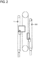
Fig. 2 shows a modification of the elevator system shown inFig. 1 with an inertia brake provided in the machine room and acting to directly brake the governor rope; -
Fig. 3 shows a configuration of an overspeed governor rope brake according to a first embodiment directly acting on the governor rope; -
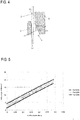
Fig. 4 shows a mathematical model of a stationary brake shoe, a movable brake shoe and a support block of the overspeed governor rope brake according to the first embodiment; -
Fig. 5 shows a relationship between a coefficient of friction and a limiting angle of attack of the overspeed governor rope brake according to the first embodiment; -
Fig. 6 shows a relationship between the angle of attack and the braking reaction force of the overspeed governor rope brake according to the first embodiment; -
Fig. 7 shows a model of the movable brake shoe assembly spring-mass system of the overspeed governor rope brake according to the first embodiment; -
Fig. 8 shows a relationship between the time and the displacement of the movable braking shoe assembly of the overspeed governor rope brake according to the first embodiment; -
Fig. 9 shows an electromagnetic overspeed governor axle brake according to a second embodiment of the invention; -
Fig. 10 shows an overspeed governor axle disc brake according to a third embodiment of the description. -
Fig. 11 shows an elevator system according to the background art - In the following, description will be made to embodiments of the present invention. It is to be understood, however, that the description is given by way of example only, and that the described embodiments are by no means to be understood as limiting the present invention thereto.
- In particular, different exemplifying embodiments will be described using, as an example of an elevator system to which the embodiments may be applied, an elevator system as depicted and explained in connection with
Figs. 1 and2 . - It is to be noted that the following examples and embodiments are to be understood only as illustrative examples. Although the specification may refer to "an", "one", or "some" example(s) or embodiment(s) in several locations, this does not necessarily mean that each such reference is related to the same example(s) or embodiment(s), or that the feature only applies to a single example or embodiment. Single features of different embodiments may also be combined to provide other embodiments. Furthermore, terms like "comprising" and "including" should be understood as not limiting the described embodiments to consist of only those features that have been mentioned; such examples and embodiments may also contain features, structures, units, modules etc. that have not been specifically mentioned.
- The general elements and functions of described elevator systems, details of which also depend on the actual type of elevator system, are known to those skilled in the art, so that a detailed description thereof is omitted herein. However, it is to be noted that several additional devices and functions besides those described below in further detail may be employed in an elevator system.
-
Fig. 1 shows anelevator system 501 having anelevator car 506 and acounterweight 507, which are both acting a moving mass and are connected to each other bysuspension ropes 513. Thesuspension ropes 513 are going around atraction wheel 512 which is driven by a hoisting machine (not shown). Because of the heavy mass hanging on both ends of thesuspension ropes 513, thesuspension ropes 513 do not slide on thetraction wheel 512. When thetraction wheel 512 is driven by the hoisting machine and rotates, theelevator car 506 and thecounterweight 507 move. Theelevator car 506 and thecounterweight 507 are guided by guide rails (not shown) which are mounted to the walls of the shaft (not shown) in which theelevator system 501 is provided. -
Fig. 1 further shows an overspeed governor (OSG)system 502 for theelevator car 506, which comprises agovernor rope 2 both ends of which are connected to the elevator car 506 (the moving mass). Thegovernor rope 2 goes around agovernor pulley 101; 201 on the top side of the elevator system and goes around atension weight pulley 509 connected to atension weight 510 on the bottom side of the elevator system. Thegovernor rope 2 is connected to theelevator car 506 via asynchronization linkage 514 having synchronization levers for tripping asafety gear 504 against both guide rails of theelevator car 506. -
Fig. 1 further shows an overspeed governor (OSG)system 552 for thecounterweight 507, which comprises agovernor rope 553 both ends of which are connected to the counterweight 507 (the moving mass). Thegovernor rope 553 goes around agovernor pulley 558 on the top side of the elevator system and goes around atension weight pulley 559 connected to atension weight 560 on the bottom side of the elevator system. Thegovernor rope 553 is connected to thecounterweight 507 via asynchronization linkage 564 having synchronization levers for tripping asafety gear 554 against both guide rails of thecounterweight 507. - Furthermore,
Fig. 1 shows that theOSG systems inertia brake 107; 207, 555 which is configured to reduce the force applied to thesynchronization linkage 514 by thegovernor rope inertia brake 107; 207, 555 is operated. In more detail, theinertia brake 107; 207, 555 is configured to dissipate the kinetic energy of the inertia of thegovernor rope Fig. 1 schematically shows that theinertia brake 107; 207, 555 acts on thegovernor pulley 101; 201, 558. However, according toFig. 2 , anotherinertia brake 1, 555' can act directly on thegovernor rope 3. - In the following,
inertia brakes 1; 101; 201 according to a first to third embodiment are described in detail. -
Fig. 3 shows an overspeed governor rope brake (OSG rope brake) 1 according to the first embodiment of the invention, illustrated infig. 2 . TheOSG rope brake 1 comprises a frame 1a for mounting the constituent members of theOSG rope brake 1 such as astationary brake shoe 3 und amovable brake shoe 4 between which anOSG rope 2 is provided. When themovable brake shoe 4 is moved upwards inFig. 3 , theOSG rope 2 is wedged between thebrake shoes OSG rope 2 is decelerated due to friction between theOSG rope 2 and thebrake shoes - The frame 1a comprises a back plate 1a1, a top plate 1a2, a bottom plate 1a3 and a right side plate 1a4. Each of the top plate 1a2, the bottom plate 1a3 and the right side plate 1a4 comprises a lug 1b2, 1b3, 1b4 to which a cover plate (not shown) can be mounted. The back plate 1a1 also comprises a lug 1b1 on the left side, which extends in the vertical direction, and the cover plate comprises a lug also extending in the vertical direction in a manner opposing the lug 1b1 of the back plate 1a1. The
OSG rope 2 is guided substantially between the lug 1b1 of the back plate 1a1 and the lug of the cover but slightly displaced to the right side, i.e. towards the inside of the frame 1a. - The
stationary brake shoe 3 is mounted from the outside of the frame 1a to the lug 1b1 of the back plate 1a1 and the lug of the cover for example by means of bolts. Thestationary brake shoe 3 comprises on its side facing the inside of the frame agroove portion 3a which protrudes towards the inside of the frame 1a and extends vertically over the entire vertical length of thestationary brake shoe 3. Thegroove portion 3a is configured to come into contact with theOSG rope 2 when themovable brake shoe 4 has been activated. The inner shape of thegroove portion 3a corresponds to the outer shape of theOSG rope 2 such that a large portion of the outer surface of theOSG rope 2 can come into contact with the friction surface inside thegroove portion 3a. - The
movable brake shoe 4 is provided opposite to thestationary brake shoe 3 on the inside of the frame 1a and is mounted to alinear traverse 5 which comprises aback plate 5a and twoside plates back plate 5a towards the outside of the frame 1a. Themovable brake shoe 4 is mounted to between theside plates pivot axis 5d allowing themovable brake shoe 4 to slightly pivot so as to ensure that the friction surface of themovable brake shoe 4 is always parallel to theOSG rope 2, i.e. extends substantially in the vertical direction. Themovable brake shoe 4 and thetraverse 5 constitute a movable brake shoe assembly. - The
linear traverse 5 comprises on its lower portion on the side facing the inside of the frame 1a a mounting plate having a first vertical portion, a horizontal portion and a second vertical portion. A traverse sidespring fixing plate 14 is formed on the horizontal portion of the mounting plate in a manner extending upwards therefrom. The traverse sidespring fixing plate 14 provides a pin on which a lower end of a later describedmain spring 7 can be fixed. Further, a latchpin holding plate 15 extends from the second vertical portion of the mounting plate and provides a latchingpin 16 on which a later describedlatch 17 can be latched. Since thelinear traverse 5 is slightly inclined with respect to the vertical direction, as will be described further below, also the vertical portions and the horizontal portion of the mounting plate are slightly inclined to the vertical and horizontal directions, respectively. - A
support block 6 is provided on the rear side of thelinear traverse 5 and comprises an inclined contact surface 6a which can come into surface contact with an outer surface of theback plate 5a. The contact surface 6a forms an angle of attack α in the range of 4° to 8° to the vertical direction. On the lower side, thesupport block 6 is pivotably mounted to the frame 1a by means of a bolt which serves as apivot point 8. The upper side of thesupport block 6 is mounted to an upper mountingportion 28. - On the left side in
Fig. 3 of the mountingportion 28, astopper 12 is provided. Thestopper 12 is comprised by twovertical side plates 12a, the lower ends of which are connected by astopper plate 12b. Thestopper plate 12b is opposed to the upper side of themovable brake shoe 4 and is adapted to stop the upward movement of themovable brake shoe 4 when the same comes into contact with thestopper plate 12b. - On the right side in
Fig. 3 of the mountingportion 28, the frame 1a comprises asupport plate portion 29 which supports anadjuster 10 and aguide rail 11 both in a manner extending towards the mountingportion 28. Theguide rail 11 is further connected to the mountingportion 28 in a manner to allow the mountingportion 28 to slide thereon towards the right side. Further, the left end of theguide rail 11 provide a stop for the mountingportion 28 limiting the movement of the mountingportion 28 in the left direction. Theadjuster 10 comprises aspring seat 10a adapted to receive the right end of alimiter spring 9 which is a compression coil spring. The left end of thelimiter spring 9 is received in a spring seat formed on a rear surface of the mountingportion 28. Thelimiter spring 9 presses the mountingportion 28 against the stop of theguide rail 11. Theadjuster 10 and theguide rail 11 both extend substantially perpendicular to the extension direction of thesupport block 6 and are thus also slightly inclined with respect to the horizontal direction. Furthermore, theadjuster 10 can be operated in a manner to change the distance between thespring seat 10a and the spring seat of the mountingportion 28 so as to change the spring force applied to the mounting portion by thespring 9 so as to adjust the brake force. In the present embodiment, the brake force is adjusted to 1500N. - A limiter side spring fixing means 13 is fixed to the mounting
portion 28 on the lateral side thereof and is adapted to receive the upper end of themain spring 7. The position of the limiter side spring fixing means 13 is such that the extensions direction of themain spring 7 in the un-activated state of theOSG rope brake 1 is slightly more inclined with respect to the vertical direction than the contact surface 6a of thesupport block 6 is inclined to the vertical direction. - The above described
latch 17 is provided below the latchpin holding plate 15 and it is provided in the form of a lever which is pivotably connected to the frame 1a via alatch pivot point 18. On the upper side, thelatch 17 comprises alatching recess 17a which can engage with the latchingpin 16 of the latchpin holding plate 15. Thelatch 17 further comprises aninclined guide surface 17b above the latchingrecess 17a along which the latchingpin 16 can slide when the latchpin holding plate 15 is moved downwardly so as to arm themovable brake shoe 4, as will be explained further below in more detail. - On its lower end, the
latch 17 is provided with aspring fixing pin 22 on which one end of alatch return spring 21 can be engaged. The other end of thelatch return spring 21 is fixed to aguide pin 23 which is guided in aguide groove 24 formed in the lower portion of asolenoid mounting pate 25. - A
solenoid 19 is mounted to thesolenoid mounting plate 25 and is configured to operate an operatingshaft 20 which is connected to thelatch 17 at a position substantially on the half-way between thelatch pivot point 18 and thespring fixing pin 22. When thesolenoid 19 is activated, the operatingshaft 20 pushes thelatch 17 to the left side inFig. 3 such that thelatch 17 pivots about thelatch pivot pin 18 against the return force of thelatch return spring 21. As a result, the latchingrecess 17a disengages from the latchingpin 16 such that thelinear traverse 5 can be pulled upwards by themain spring 7. Since the spring load of themain spring 7 acts between the latchingpin 16 and the latchingrecess 17a, a needle roller bearing is provided over the latchingpin 16 so as to reduce the friction force between the latchingpin 16 and the latchingrecess 17. - By using the
solenoid 19 for deploying theOSG rope brake 1, unwanted braking can be avoided. A signal for engaging the brake can be taken from a main contactor signal from the elevator controller. - A
switch 27 is mounted to the upper end of thesolenoid mounting plate 25 to monitor the engagement/disengagement status of theOSG rope brake 1. -
Fig. 3 shows also alinear actuator 26 which is mounted to the frame 1a at a position below thelinear traverse 5 and comprises an armingshaft 26a which is connected to thelinear traverse 5. In more detail, the armingshaft 26a comprises at its top end a laterally extending mountingpin 26b having its both ends guided inrespective guide slots 5e formed in theside plates traverse 5.Fig. 3 shows a state in which the mountingpin 26b is not yet mounted to theguide slots 5e. Thepins 26b comprise linear ball bearings which provide an extremely low dynamic friction when sliding in theguide slots 5e. Theguide slots 5e are formed substantially parallel to the contact surface 6a of thesupport block 6. - As regards the
solenoid 19 and thelinear actuator 26, an uninterrupted power supply (UPS) should be used to resolve building wide power loss situations. Also, a robust control logic is required. - Now, the operation of the
rope brake 1 is described as follows. Starting from the state shown inFig. 3 , therope brake 1 is armed by operating the linear actuator in such a manner that thetraverse 5 is pulled downwards against the spring force of themain spring 7. During this movement of thetraverse 5, the latchingpin 16 comes into contact with theguide surface 17b of thelatch 17. As a result, thelatch 17 is pivoted about thelatch pivot point 18 against the return force of thereturn spring 21 until the latchingpin 16 engages with the latchingrecess 17a. In this state, therope brake 1 is armed in sense of that themain spring 6 is loaded to apply a spring force to thetraverse 5. Also, in this state, themovable brake shoe 4 is moved away from thestationary brake shoe 3 such that no braking force is acting on theOSG rope 2. - Then, when the machinery brake of the elevator decelerates the elevator car so as to perform a quick stop of the elevator car while the elevator car is moving upward, the
OSG rope 2 needs to be braked so as to avoid unintended safety gear tripping. For this purpose, thesolenoid 19 is electronically operated such that the operatingshaft 20 is pushed out and thelatch 17 rotates about thelatch pivot point 18. As a result, the latchinggroove 17a releases the engagement of the latchingpin 16 and thus allows the movement of thetraverse 5. With the movement being allowed, the spring force of themain spring 7 acts on thetraverse 5 and pulls the same upwards while thetraverse 5 is guided along the contact surface 6a of thesupport block 6 which supports thetraverse 5 and thus themovable brake shoe 4 from the left side inFig. 3 . As a result, themovable brake shoe 4 which is mounted to thetraverse 5 comes into contact with theOSG rope 2 and presses theOSG rope 2 into thegroove portion 3a of thestationary brake shoe 3 such that a frictional force acts between theOSG rope 2 and a friction surface 4a of themovable brake shoe 4 and friction surfaces of thegroove portion 3a. Hence, theOSG rope 2 is decelerated. - Furthermore, since the
OSG rope 2 is moving upward with respect to therope brake 1, the above explained friction force brings about the effect that a further upwardly directed force is applied to themovable brake shoe 4 in addition to the spring force of themain spring 7 such that themovable brake shoe 4 moves further upward and is pressed against the inclined contact surface 6a of thesupport block 6 thus generating a self-latching force. Because the support surface 6a of thesupport block 6 and theback plate 5a of thetraverse 5 are inclined with respect to the friction surface 4a of themovable brake shoe 4, the upward movement of thetraverse 5 pushes thesupport block 6 horizontally such that thesupport block 6 pivots about thepivot point 8 against the spring force of thelimiter spring 9. This pivoting movement of thesupport block 6 results in that the upper mountingportion 28 moves to the right side inFig. 3 while being guided on theguide rail 11 thus compressing thelimiter spring 9. As a result, themovable brake shoe 4 moves away from thestationary brake shoe 3 so that the distance between bothbrake shoes limiter spring 9. - The pivoting movement of the
support block 6 is limited by the limited movement of themovable brake shoe 4 established by thestopper 12 of the upper mountingportion 28. When the friction force between therope 2 and themovable brake shoe 4 is very large, themovable brake shoe 4 is moved upward until it contacts thestopper plate 12b of thestopper 12. - When the quick stop of the elevator car is finished, the
linear actuator 26 is operated so as to release themovable brake shoe 4 from between thestationary brake shoe 3 and thesupport block 6 and to arm thetraverse 5 for the next quick stop by engaging the latchingpin 16 with the latchinggroove 17a of thelatch 17. Therein, thelinear actuator 26 overcomes the self-locking force generated by themovable brake shoe 4 being wedged between thestationary brake shoe 3 and thesupport block 6, as well as the spring force of themain spring 7. The status and the position of the moving components (the movable brake shoe assembly) is detected by limit switches and a built-in potentiometer on thelinear actuator 26. - Now the self-locking behaviour of the
tope brake 1 is explained on the basis ofFig. 4 which shows the geometry of thestationary brake shoe 3, themovable brake shoe 4, therope 2 and thesupport block 6 as well as the forces and the rope velocity acting thereon. - The symbol v refers to the velocity of the
overspeed governor rope 2, µ refers to the coefficient of friction between therope 2 and thebrake shoes rope 2, Fµ refers to the reaction force of Fµr, Fa refers to the force of themain spring 7, Fb refers to the normal force which is normal to the inclined contact surface 6a of thesupport block 6, F1 refers to the force of therope 2 on the moving brake shoe 4 (reaction force of the braking force), a refers to the limiting angel of attack which is defined between the contact surface 6a and the vertical direction, i.e. the direction parallel to the friction surface of themovable brake shoe 4. - In the following analysis, the gravity is ignored for simplicity. During operation, the brake generates the friction force Fµr on the
OSG rope 2. The reaction force Fµ is split between the two brake surfaces of themovable brake shoe 4 and thestationary brake shoe 3. As is explained above, the movement of themovable brake shoe 3 is guided by means of theguide slots 5e and the linear ball bearings of thelinear actuator 26 whose dynamic friction is extremely low and can be ignored in this mathematical analysis. - The friction force and its reaction force are given as follows

- The value of the reaction force is given by

- Since the force will be divided into two parts, the force on each
brake shoe - The limiting angle of attack is given as

- Given that µ = 0,15, F1 = 4000N and Fα = 200N, then α = 11,3° and Fµr = 1200N.
- This angle α is to be understood as a limit angle above which the self-locking action is not working. This means, that the angle of the inclined contact surface 6a of the support block needs to be smaller than the limit angle α so as to ensure the self-locking action.
Fig. 5 shows the dependency of the limit angle α on the coefficient of friction for different forces Fa of themain spring 7. - Furthermore, the equation of (3) can be formulated as follows: F1 = Fa / (tan(α) - µ). As can be seen from this equation, when tan(α) approaches µ, the force F1 will tend to be infinity which allows the conclusion that this corresponds to the locking behaviour. It is further indicated that this model is not valid for angles at which tan(α) ≤ µ.
-
Fig. 6 shows values of the brake force F1 for different angles α and different forces Fa of themain spring 7. The plots inFig. 6 indicate parameter values which will result in proper self-locking behaviour, but the model does not take into account the force limiting system provided by thesupport block 6 which is pivotable against the spring force of thelimiter spring 9. - Now, the movement of the moving brake shoe assembly comprising the
movable brake shoe 4 and thetraverse 5 is described on which the spring force of themain spring 7 is acting. When therope brake 1 is operated, the moving brake shoe assembly is free to accelerate to the movement along the linear ball bearings of theactuator 26 for example for about 50mm. Thereafter, themovable brake shoe 4 comes into contact with theOSG rope 2. Within this free travel, the components act as a simple, almost undamped spring-mass system. The following analysis is limited to the period until the time point of contact between the moving brake assembly with theOSG rope 2 because thereafter, the system will be too complex for analytic solution. Also, friction forces are not taken into account and gravity will effect only the equilibrium position of the mass but not the relative displacement from the equilibrium position. In the device according to the embodiment, the equilibrium position will never be reached because the movable brake shoe assembly makes contact with theOSG rope 2 before reaching the equilibrium position. -
Fig. 7 shows the moving brake shoe assembly as a spring-mass system. - The free displacement is given by

- x1 (t) ... Displacement of assembly/mass from system equilibrium position
- x0 ... Initial displacement from equilibrium position
- ω ... Angular velocity of mass-spring system
- k ... Spring constant
- m ... Lumped mass of moving brake shoe assembly and effective spring mass
- At equilibrium, the spring is stretched by a force of mg cos(α). The angle of attack α (angle with respect to the vertical direction) is small such as in the order of 5°. Hence, it can be concluded that cos (5°) ≈ 1. For this reasons, it can be assumed that the system is vertical.
- For this analysis, four different springs were modelled.
Spring number k(N/mm) m = 6kg 1 4,37 2 4,37 3 2,19 4 1,42 - For each spring, the parameters ω and x0 are different and depend on the spring parameters. The unloaded spring length is l0 = 176 ... 196 mm. The spring is loaded by gravity and the resulting change in length is given by

- Δleq ... length change of spring at equilibrium
- F0 ... Preload force of spring
- The initial displacement from the equilibrium position is given by


- lmax ... Maximum spring length when moving brake shoe assembly is armed
- leq ... Equilibrium length of spring
- At deployment (t=0s), the displacement from rest, or the armed position x(t) is given by

Fig. 8 -
Fig. 8 shows the displacement x(t) for four different springs. - In the
OSG rope brake 1 of the first embodiment, when thesolenoid 19 is operated, themovable brake shoe 4 and the relatedlinear traverse 5 move along a linear path at the angle of attack α provided by the inclined surface 6a by being pulled by themain spring 7. The angle of attack α is determined such that the brake becomes self-locking after a suitable initial force has been administered by themain spring 7. When themovable brake shoe 4 contacts theOSG rope 2, it begins to brake theOSG rope 2 by friction. The movement of theOSG rope 2 moves the movable brake shoe further along the inclined surface 6a thus increasing the contact pressure between the movable brake shoe assembly and the inclined surface 6a of thesupport block 6. In turn, this increased contact pressure increases the brake force such that the system is self-boosting. Due to the mechanical structure of thestationary brake shoe 3, themovable brake shoe 4 and thesupport block 6, this self-boosting feature activates only in the desired direction, i.e. the direction in which theOSG rope 2 moves when the elevator car is moving upward. By contrast, when the OSG rope brake is unintentionally[KP1] operated when the elevator car moves in the downward direction and theOSG rope 2 shall not be braked, themovable brake shoe 4 will be pulled by the movement of theOSG rope 2 in the direction to open the brake. In this direction, the inclined surface 6a does not act on themovable brake shoe 4 such that there is no effect of self-boosting. The only force acting on themovable brake shoe 4 is the spring force of themain spring 7, which, however provides no noticeable brake force. - With the
OSG rope brake 1 according to this embodiment, unintended activation of the safety gear is avoided in case of unplanned rapid stopping in upward direction, such as a so-called quick stop. - Further, existing overspeed governor components can be extended to higher elevator travels.
- The dissipation of the energy of the rope inertia can be well controlled and obtained to a high level.
- The
OSG rope brake 1 can easily be monitored and the equipment can be mounted to the machine room and need not to be mounted to the shaft. - In a modification of the present embodiment, the
support block 6 can also be provided in a manner to be linearly movable in the direction substantially perpendicular to the inclined surface 6a instead of being pivotable. In this modification, a pair oflimiter spring 9 andguide rail 11 control the linear movement of thesupport block 6. -
Fig. 9 shows anoverspeed governor 100 having apulley 101 attached to anaxle 102 which is supported bybearings housing Fig. 9 , is laid over thepulley 101 and the overspeed governor rope transmits its movement to thepulley 101 via friction. Hence, when an elevator car connected to the overspeed governor rope moves, the overspeed governor rope moves together with the elevator car and makes thepulley 101 rotate. When the moving speed of thepulley 101 exceeds a certain threshold, a braking mechanism (not shown) is activated which totally brakes down thepulley 101 and thus the overspeed governor rope and brings the elevator car to stop. - The
overspeed governor 100 further comprises an electromagneticOSG axle brake 107 which is constituted substantially by arotating armature 108 and acoil housing 109. In this embodiment, thecoil housing 109 is fixed to the bearinghousing 106 and has a substantially ring-like shape with a substantially ring-shapedcoil 110 being placed in the coil hosing 109. On the side facing away from thepulley 101, thecoil housing 109 comprises a ring-shaped friction surface 111 having the property of providing a suitable frictional coefficient for braking purposes. - The
rotating armature 108 has a disc-like shape and its surface opposing the friction surface 111 of thecoil housing 109 is also a friction surface 115 having the property of providing a suitable frictional coefficient for braking purposes. Therotating armature 108 is connected to anarmature hub 112 which is mounted to a one-way backstop bearing 113 via abolt 114. The one-way backstop bearing 113 is fixed to a protrudingportion 102a of theaxle 102 which protrudes from the bearinghousing 106 in the direction opposite to thepulley 101. The one-way backstop bearing 113 has the property that it allows therotating armature 108 to rotate together with theshaft 102 only in one rotation direction of theshaft 102, wherein this rotation direction corresponds to the direction in which the elevator car moves upwards. Furthermore, the rotatingarmature 108 is made from a magnetic material. - When the
coil 110 is energized, the rotatingarmature 108 is electromagnetically attracted to thecoil housing 109 thus generating a brake force. When thecoil 110 is de-energized, not-shown springs act to displace therotating armature 108 and thecoil housing 110 from each other so as to disengage thebrake 107. - The operation of electromagnetic
OSG axle brake 107 will be explained further below. -
Fig. 10 shows anoverspeed governor 200 which is similar to theoverspeed governor 100 ofFig. 9 . Theoverspeed governor 200 has apulley 201 attached to anaxle 202 which is supported bybearings housing Fig. 10 , is laid over thepulley 201 and the overspeed governor rope transmits its movement to thepulley 201 via friction. Hence, when an elevator car connected to the overspeed governor rope moves, the overspeed governor rope moves together with the elevator car and makes thepulley 201 rotate. When the moving speed of thepulley 201 exceeds a certain threshold, a braking mechanism is activated which totally brakes down thepulley 201 and thus the overspeed governor rope and brings the elevator car to stop. - The
overspeed governor 200 further comprises an OSGaxle disc brake 207 which is constituted substantially by arotating brake disc 208 and acalliper 209. In this embodiment, thecalliper 209 is fixed to the bearinghousing 206 and housesbrake pads rotating brake disc 208 by operating a brake cylinder also provided in thecalliper 209. The brake cylinder is hydraulically operated and the hydraulic pressure in the brake cylinder can be controlled by a hydraulic circuit having an electromagnetic valve (not shown). Furthermore, when the brake cylinder is not operated, not-shown springs acts to displace thebrake pads brake 207. - The
brake disc 208 has a disc-like shape and its surfaces opposing the friction surfaces of thebrake pads calliper 209 are also friction surfaces having the property of providing a suitable frictional coefficient for braking purposes. Thebrake disc 208 is mounted to a one-way backstop bearing 213 via a bolts. The one-way backstop bearing 213 is fixed to a protrudingportion 202a of theaxle 202. The one-way backstop bearing 213 has the property that it allows thebrake disc 208 to rotate together with theshaft 202 only in one rotation direction of theshaft 202, wherein this rotation direction corresponds to the direction in which the elevator car moves upwards. - When the hoisting machinery of the elevator is operated to perform a quick stop of the elevator car, the governor rope is strongly decelerated. So as to avoid an unintentional safety gear tripping, the overspeed governor rope has to be decelerated by means of the
OSG axle brake - In the second embodiment, the
coil 110 of the OSG axle brake is energized to a certain amount such that therotating armature 108 is attracted to thecoil housing 109, thus generating a brake force by means of the two friction surfaces 111 and 115. - In the third embodiment, the electromagnetic valve (not shown) is operated to a certain amount such that the
brake pads calliper 209 are pressed against therotating brake disc 208, thus generating a brake force by means of the friction surfaces between thebrake pads rotating brake disc 208. - The dissipated energy of the governor rope's inertia can be controlled by adjusting the voltage and/or current applied to the coil 110 (second embodiment) or the electromagnetic valve (third embodiment). This control is configured in a manner that the brake force applied by the inertia brake to the overspeed governor rope is limited to a specific limit brake force such that the rope does not slip on the
pulley pulley - Furthermore, due to the one-way backstop bearing 113, 213, even when the
brakes rotating armature 108 or thebrake disc 208 will not be transmitted to theaxle brakes - Both
brakes - With the
brakes - Further, existing overspeed governor components can be extended to higher elevator travels.
- The dissipation of the energy of the rope inertia can be well-controlled and obtained to a high level.
- Compared to alternative solutions, a robust design with few parts can be obtained.
- The
brakes - Further, the
brakes brakes - Compared to the OSG rope brake of the first embodiment,
OSG axle brakes
Claims (15)
- Inertia brake (1) for braking an overspeed governor rope (2) of an overspeed governor system of an elevator system, wherein the inertia brake (1) is adapted to apply a brake force to the overspeed governor rope (2) upon quick stop of the elevator system only when the overspeed governor rope (2) moves in one direction and not to apply the brake force to the overspeed governor rope (2) when the overspeed governor rope (2) moves in the other direction.
- Inertia brake (1) according to claim 2, wherein the inertia brake (1) is adapted to limit the brake force applied by the inertia brake (1) to the overspeed governor rope (2) to a specific limit brake force.
- Inertia brake (1) according to claim 1 or 2, wherein the inertia brake (1) is a rope brake comprising:a stationary brake shoe (3) and a movable brake shoe assembly at least comprising a movable brake shoe (4), wherein the overspeed governor rope (2) is guided between the stationary brake shoe (3) and the movable brake shoe (4),a support block (6) having an inclined contact surface (6a) for supporting the movable brake shoe (4) when the rope brake is activated, anda main spring (7) for urging the movable brake shoe assembly toward the inclined contact surface (6a).
- Inertia brake (1) according to any one of the preceding claims, wherein the support block (6) is movably mounted to a frame (1a) of the inertia brake (1) so as to be movable in a direction substantially perpendicular to the inclined contact surface (6a).
- Inertia brake (1) according to any one of claims 1 to 3, wherein the support block (6) is pivotably mounted to a frame (1a) of the inertia brake (1) at a pivot point (8) which is provided on the side of the support block (6) from which the movable brake shoe assembly is urged toward the inclined surface (6a) by the main spring (7).
- Inertia brake (1) according to claim 4 or 5, further comprising a limiter spring (9) which acts against the movement of the support block (6) away from the overspeed governor rope (2) by applying a spring force urging the support block (6) toward the governor rope (2).
- Inertia brake (1) according to any of claims 3 to 6, further comprising a deployment mechanism for deploying the movable brake shoe assembly from an armed state in which the movable brake shoe assembly is engaged and displaced from the inclined contact surface (6a) of the support block (6) into a deployed state in which the main spring (7) is allowed to urge the movable main spring assembly against the inclined contact surface (6a).
- Inertia brake (1) according to any one of claims 3 to 7, further comprising an arming mechanism for moving the movable brake shoe assembly away from the inclined contact surface (6a) and for bringing the movable brake shoe assembly into the armed state.
- Inertia brake (107; 207) according to claim 1 or 2, wherein the overspeed system (100; 200) comprises a pulley (101; 201) attached to an axle (102; 202), wherein the inertia brake (107; 207) is an axle brake having a friction surface which is operatively connected with the axle (102; 202) only when the overspeed governor rope moves in said one direction.
- Inertia brake (107) according to claim 9, wherein the inertia brake (107) is an electromagnetic axle brake having a coil (110) adapted to apply an electromagnetic attraction force to a rotating armature (108) connected to the axle (102) when the coil (110) is energized.
- Inertia brake (107) according to claim 10, further comprising a one-way backstop bearing (113) allowing the rotating armature (108) to rotate only in one rotation direction in relation to the axle (102; 202).
- Inertia brake (207) according to claim 9, wherein the inertia brake (207) is an axle disc brake having a brake disc (208) connected to the axle (202) and having a brake cylinder adapted to press brake pads (210, 211) towards the brake disc (208) when the brake cylinder is operated.
- Inertia brake (207) according to claim 12, further comprising a one-way backstop bearing (213) allowing the brake disc (208) to rotate only in one rotation direction in relation to the axle (102; 202).
- Overspeed governor system for an elevator car (506), the overspeed governor system comprising an inertia brake (1; 107; 207) according to any one of the preceding claims and an overspeed governor rope (2), wherein the one direction is the upward moving direction of the elevator car (506).
- Overspeed governor system for a counterweight, the overspeed governor system comprising an inertia brake (1; 107; 207) according to any one of the preceding claims and an overspeed governor rope (2), wherein the one direction is the upward moving direction of the counterweight.
Priority Applications (1)
| Application Number | Priority Date | Filing Date | Title |
|---|---|---|---|
| EP18153484.3A EP3517473A1 (en) | 2018-01-25 | 2018-01-25 | Inertia brake for braking a governor rope of a governor system of an elevator system |
Applications Claiming Priority (1)
| Application Number | Priority Date | Filing Date | Title |
|---|---|---|---|
| EP18153484.3A EP3517473A1 (en) | 2018-01-25 | 2018-01-25 | Inertia brake for braking a governor rope of a governor system of an elevator system |
Publications (1)
| Publication Number | Publication Date |
|---|---|
| EP3517473A1 true EP3517473A1 (en) | 2019-07-31 |
Family
ID=61027581
Family Applications (1)
| Application Number | Title | Priority Date | Filing Date |
|---|---|---|---|
| EP18153484.3A Withdrawn EP3517473A1 (en) | 2018-01-25 | 2018-01-25 | Inertia brake for braking a governor rope of a governor system of an elevator system |
Country Status (1)
| Country | Link |
|---|---|
| EP (1) | EP3517473A1 (en) |
Cited By (2)
| Publication number | Priority date | Publication date | Assignee | Title |
|---|---|---|---|---|
| CN113247729A (en) * | 2021-05-19 | 2021-08-13 | 李宏 | Elevator safety performance parameter measuring device, measuring method and application |
| CN119191029A (en) * | 2024-11-05 | 2024-12-27 | 浙江飞亚电梯有限公司 | Elevator counterweight balancing device with noise reduction structure |
Citations (6)
| Publication number | Priority date | Publication date | Assignee | Title |
|---|---|---|---|---|
| US4083432A (en) * | 1976-12-01 | 1978-04-11 | Otis Elevator Company | Safety arrangement |
| CA2081136A1 (en) * | 1991-10-25 | 1993-04-26 | Tsutomu Shiina | Elevator governor with rope catching mechanism |
| JPH05213556A (en) * | 1992-01-09 | 1993-08-24 | Otis Elevator Co | Malfunction preventing device for governor for elevator |
| JPH0776471A (en) * | 1993-09-08 | 1995-03-20 | Toshiba Corp | Governor device for elevator |
| EP0980842A1 (en) * | 1998-08-14 | 2000-02-23 | Inventio Ag | Device for stopping an elevator installation |
| WO2015173913A1 (en) * | 2014-05-14 | 2015-11-19 | 三菱電機株式会社 | Elevator device and control method therefor |
-
2018
- 2018-01-25 EP EP18153484.3A patent/EP3517473A1/en not_active Withdrawn
Patent Citations (6)
| Publication number | Priority date | Publication date | Assignee | Title |
|---|---|---|---|---|
| US4083432A (en) * | 1976-12-01 | 1978-04-11 | Otis Elevator Company | Safety arrangement |
| CA2081136A1 (en) * | 1991-10-25 | 1993-04-26 | Tsutomu Shiina | Elevator governor with rope catching mechanism |
| JPH05213556A (en) * | 1992-01-09 | 1993-08-24 | Otis Elevator Co | Malfunction preventing device for governor for elevator |
| JPH0776471A (en) * | 1993-09-08 | 1995-03-20 | Toshiba Corp | Governor device for elevator |
| EP0980842A1 (en) * | 1998-08-14 | 2000-02-23 | Inventio Ag | Device for stopping an elevator installation |
| WO2015173913A1 (en) * | 2014-05-14 | 2015-11-19 | 三菱電機株式会社 | Elevator device and control method therefor |
Cited By (2)
| Publication number | Priority date | Publication date | Assignee | Title |
|---|---|---|---|---|
| CN113247729A (en) * | 2021-05-19 | 2021-08-13 | 李宏 | Elevator safety performance parameter measuring device, measuring method and application |
| CN119191029A (en) * | 2024-11-05 | 2024-12-27 | 浙江飞亚电梯有限公司 | Elevator counterweight balancing device with noise reduction structure |
Similar Documents
| Publication | Publication Date | Title |
|---|---|---|
| EP2688825B1 (en) | Elevator braking system | |
| KR101227710B1 (en) | Progressive safety gear | |
| CN108367892B (en) | Robust Electrical Safety Actuation Module | |
| US9688511B2 (en) | Brake | |
| CN102791604B (en) | Actuators and lift installations for braking equipment | |
| US5007505A (en) | Elevator traction sheave brake | |
| KR20080052449A (en) | Braking system for maintaining and braking the elevator cab and maintaining and braking method | |
| KR102605526B1 (en) | Braking system for a hoisted structure and method of controlling braking a hoisted structure | |
| EP2636626A1 (en) | Elevator device | |
| KR20100082851A (en) | Lift drive and method for driving and detaining a lift car, a corresponding method and a braking device, and method for decelerating and detaining a lift car, and an associated method | |
| CN110790109B (en) | Electric safety actuator assembly for elevator system | |
| EP3328772B1 (en) | Safety block for elevator | |
| CN111032555B (en) | Elevator emergency brake with brake shoe | |
| US11597633B2 (en) | Elevator safety brake, elevator and method for testing elevator safety brakes | |
| HK40025291A (en) | Elevator safety brake, elevator and method for testing elevator safety brakes | |
| HK1236175B (en) | Braking system for a hoisted structure and method of controlling braking a hoisted structure | |
| HK1192209A (en) | Elevator braking system | |
| HK1192209B (en) | Elevator braking system |
Legal Events
| Date | Code | Title | Description |
|---|---|---|---|
| PUAI | Public reference made under article 153(3) epc to a published international application that has entered the european phase |
Free format text: ORIGINAL CODE: 0009012 |
|
| STAA | Information on the status of an ep patent application or granted ep patent |
Free format text: STATUS: THE APPLICATION HAS BEEN PUBLISHED |
|
| AK | Designated contracting states |
Kind code of ref document: A1 Designated state(s): AL AT BE BG CH CY CZ DE DK EE ES FI FR GB GR HR HU IE IS IT LI LT LU LV MC MK MT NL NO PL PT RO RS SE SI SK SM TR |
|
| AX | Request for extension of the european patent |
Extension state: BA ME |
|
| STAA | Information on the status of an ep patent application or granted ep patent |
Free format text: STATUS: REQUEST FOR EXAMINATION WAS MADE |
|
| 17P | Request for examination filed |
Effective date: 20200107 |
|
| RBV | Designated contracting states (corrected) |
Designated state(s): AL AT BE BG CH CY CZ DE DK EE ES FI FR GB GR HR HU IE IS IT LI LT LU LV MC MK MT NL NO PL PT RO RS SE SI SK SM TR |
|
| GRAP | Despatch of communication of intention to grant a patent |
Free format text: ORIGINAL CODE: EPIDOSNIGR1 |
|
| STAA | Information on the status of an ep patent application or granted ep patent |
Free format text: STATUS: GRANT OF PATENT IS INTENDED |
|
| INTG | Intention to grant announced |
Effective date: 20210204 |
|
| STAA | Information on the status of an ep patent application or granted ep patent |
Free format text: STATUS: THE APPLICATION IS DEEMED TO BE WITHDRAWN |
|
| 18D | Application deemed to be withdrawn |
Effective date: 20210615 |