EP3517444A1 - Mât d'aeronef comprenant un echangeur thermique coaxial - Google Patents
Mât d'aeronef comprenant un echangeur thermique coaxial Download PDFInfo
- Publication number
- EP3517444A1 EP3517444A1 EP18212157.4A EP18212157A EP3517444A1 EP 3517444 A1 EP3517444 A1 EP 3517444A1 EP 18212157 A EP18212157 A EP 18212157A EP 3517444 A1 EP3517444 A1 EP 3517444A1
- Authority
- EP
- European Patent Office
- Prior art keywords
- flow
- conduit
- aircraft
- heat exchanger
- primary structure
- Prior art date
- Legal status (The legal status is an assumption and is not a legal conclusion. Google has not performed a legal analysis and makes no representation as to the accuracy of the status listed.)
- Granted
Links
Images

Classifications
-
- B—PERFORMING OPERATIONS; TRANSPORTING
- B64—AIRCRAFT; AVIATION; COSMONAUTICS
- B64D—EQUIPMENT FOR FITTING IN OR TO AIRCRAFT; FLIGHT SUITS; PARACHUTES; ARRANGEMENT OR MOUNTING OF POWER PLANTS OR PROPULSION TRANSMISSIONS IN AIRCRAFT
- B64D13/00—Arrangements or adaptations of air-treatment apparatus for aircraft crew or passengers, or freight space
- B64D13/06—Arrangements or adaptations of air-treatment apparatus for aircraft crew or passengers, or freight space the air being conditioned
- B64D13/08—Arrangements or adaptations of air-treatment apparatus for aircraft crew or passengers, or freight space the air being conditioned the air being heated or cooled
-
- B—PERFORMING OPERATIONS; TRANSPORTING
- B64—AIRCRAFT; AVIATION; COSMONAUTICS
- B64D—EQUIPMENT FOR FITTING IN OR TO AIRCRAFT; FLIGHT SUITS; PARACHUTES; ARRANGEMENT OR MOUNTING OF POWER PLANTS OR PROPULSION TRANSMISSIONS IN AIRCRAFT
- B64D27/00—Arrangement or mounting of power plants in aircraft; Aircraft characterised by the type or position of power plants
- B64D27/02—Aircraft characterised by the type or position of power plants
- B64D27/16—Aircraft characterised by the type or position of power plants of jet type
- B64D27/18—Aircraft characterised by the type or position of power plants of jet type within, or attached to, wings
-
- B—PERFORMING OPERATIONS; TRANSPORTING
- B64—AIRCRAFT; AVIATION; COSMONAUTICS
- B64D—EQUIPMENT FOR FITTING IN OR TO AIRCRAFT; FLIGHT SUITS; PARACHUTES; ARRANGEMENT OR MOUNTING OF POWER PLANTS OR PROPULSION TRANSMISSIONS IN AIRCRAFT
- B64D27/00—Arrangement or mounting of power plants in aircraft; Aircraft characterised by the type or position of power plants
- B64D27/40—Arrangements for mounting power plants in aircraft
- B64D27/402—Arrangements for mounting power plants in aircraft comprising box like supporting frames, e.g. pylons or arrangements for embracing the power plant
-
- B—PERFORMING OPERATIONS; TRANSPORTING
- B64—AIRCRAFT; AVIATION; COSMONAUTICS
- B64D—EQUIPMENT FOR FITTING IN OR TO AIRCRAFT; FLIGHT SUITS; PARACHUTES; ARRANGEMENT OR MOUNTING OF POWER PLANTS OR PROPULSION TRANSMISSIONS IN AIRCRAFT
- B64D29/00—Power-plant nacelles, fairings or cowlings
- B64D29/02—Power-plant nacelles, fairings or cowlings associated with wings
-
- B—PERFORMING OPERATIONS; TRANSPORTING
- B64—AIRCRAFT; AVIATION; COSMONAUTICS
- B64D—EQUIPMENT FOR FITTING IN OR TO AIRCRAFT; FLIGHT SUITS; PARACHUTES; ARRANGEMENT OR MOUNTING OF POWER PLANTS OR PROPULSION TRANSMISSIONS IN AIRCRAFT
- B64D33/00—Arrangement in aircraft of power plant parts or auxiliaries not otherwise provided for
- B64D33/02—Arrangement in aircraft of power plant parts or auxiliaries not otherwise provided for of combustion air intakes
-
- B—PERFORMING OPERATIONS; TRANSPORTING
- B64—AIRCRAFT; AVIATION; COSMONAUTICS
- B64D—EQUIPMENT FOR FITTING IN OR TO AIRCRAFT; FLIGHT SUITS; PARACHUTES; ARRANGEMENT OR MOUNTING OF POWER PLANTS OR PROPULSION TRANSMISSIONS IN AIRCRAFT
- B64D33/00—Arrangement in aircraft of power plant parts or auxiliaries not otherwise provided for
- B64D33/08—Arrangement in aircraft of power plant parts or auxiliaries not otherwise provided for of power plant cooling systems
-
- B—PERFORMING OPERATIONS; TRANSPORTING
- B64—AIRCRAFT; AVIATION; COSMONAUTICS
- B64D—EQUIPMENT FOR FITTING IN OR TO AIRCRAFT; FLIGHT SUITS; PARACHUTES; ARRANGEMENT OR MOUNTING OF POWER PLANTS OR PROPULSION TRANSMISSIONS IN AIRCRAFT
- B64D33/00—Arrangement in aircraft of power plant parts or auxiliaries not otherwise provided for
- B64D33/08—Arrangement in aircraft of power plant parts or auxiliaries not otherwise provided for of power plant cooling systems
- B64D33/10—Radiator arrangement
-
- F—MECHANICAL ENGINEERING; LIGHTING; HEATING; WEAPONS; BLASTING
- F01—MACHINES OR ENGINES IN GENERAL; ENGINE PLANTS IN GENERAL; STEAM ENGINES
- F01D—NON-POSITIVE DISPLACEMENT MACHINES OR ENGINES, e.g. STEAM TURBINES
- F01D25/00—Component parts, details, or accessories, not provided for in, or of interest apart from, other groups
- F01D25/08—Cooling; Heating; Heat-insulation
- F01D25/12—Cooling
-
- F—MECHANICAL ENGINEERING; LIGHTING; HEATING; WEAPONS; BLASTING
- F01—MACHINES OR ENGINES IN GENERAL; ENGINE PLANTS IN GENERAL; STEAM ENGINES
- F01D—NON-POSITIVE DISPLACEMENT MACHINES OR ENGINES, e.g. STEAM TURBINES
- F01D25/00—Component parts, details, or accessories, not provided for in, or of interest apart from, other groups
- F01D25/24—Casings; Casing parts, e.g. diaphragms, casing fastenings
-
- F—MECHANICAL ENGINEERING; LIGHTING; HEATING; WEAPONS; BLASTING
- F02—COMBUSTION ENGINES; HOT-GAS OR COMBUSTION-PRODUCT ENGINE PLANTS
- F02C—GAS-TURBINE PLANTS; AIR INTAKES FOR JET-PROPULSION PLANTS; CONTROLLING FUEL SUPPLY IN AIR-BREATHING JET-PROPULSION PLANTS
- F02C6/00—Plural gas-turbine plants; Combinations of gas-turbine plants with other apparatus; Adaptations of gas-turbine plants for special use
- F02C6/04—Gas-turbine plants providing heated or pressurised working fluid for other apparatus, e.g. without mechanical power output
-
- F—MECHANICAL ENGINEERING; LIGHTING; HEATING; WEAPONS; BLASTING
- F02—COMBUSTION ENGINES; HOT-GAS OR COMBUSTION-PRODUCT ENGINE PLANTS
- F02C—GAS-TURBINE PLANTS; AIR INTAKES FOR JET-PROPULSION PLANTS; CONTROLLING FUEL SUPPLY IN AIR-BREATHING JET-PROPULSION PLANTS
- F02C6/00—Plural gas-turbine plants; Combinations of gas-turbine plants with other apparatus; Adaptations of gas-turbine plants for special use
- F02C6/04—Gas-turbine plants providing heated or pressurised working fluid for other apparatus, e.g. without mechanical power output
- F02C6/06—Gas-turbine plants providing heated or pressurised working fluid for other apparatus, e.g. without mechanical power output providing compressed gas
- F02C6/08—Gas-turbine plants providing heated or pressurised working fluid for other apparatus, e.g. without mechanical power output providing compressed gas the gas being bled from the gas-turbine compressor
-
- F—MECHANICAL ENGINEERING; LIGHTING; HEATING; WEAPONS; BLASTING
- F02—COMBUSTION ENGINES; HOT-GAS OR COMBUSTION-PRODUCT ENGINE PLANTS
- F02C—GAS-TURBINE PLANTS; AIR INTAKES FOR JET-PROPULSION PLANTS; CONTROLLING FUEL SUPPLY IN AIR-BREATHING JET-PROPULSION PLANTS
- F02C7/00—Features, components parts, details or accessories, not provided for in, or of interest apart form groups F02C1/00 - F02C6/00; Air intakes for jet-propulsion plants
- F02C7/04—Air intakes for gas-turbine plants or jet-propulsion plants
- F02C7/047—Heating to prevent icing
-
- F—MECHANICAL ENGINEERING; LIGHTING; HEATING; WEAPONS; BLASTING
- F02—COMBUSTION ENGINES; HOT-GAS OR COMBUSTION-PRODUCT ENGINE PLANTS
- F02C—GAS-TURBINE PLANTS; AIR INTAKES FOR JET-PROPULSION PLANTS; CONTROLLING FUEL SUPPLY IN AIR-BREATHING JET-PROPULSION PLANTS
- F02C7/00—Features, components parts, details or accessories, not provided for in, or of interest apart form groups F02C1/00 - F02C6/00; Air intakes for jet-propulsion plants
- F02C7/12—Cooling of plants
- F02C7/16—Cooling of plants characterised by cooling medium
- F02C7/18—Cooling of plants characterised by cooling medium the medium being gaseous, e.g. air
- F02C7/185—Cooling means for reducing the temperature of the cooling air or gas
-
- F—MECHANICAL ENGINEERING; LIGHTING; HEATING; WEAPONS; BLASTING
- F28—HEAT EXCHANGE IN GENERAL
- F28D—HEAT-EXCHANGE APPARATUS, NOT PROVIDED FOR IN ANOTHER SUBCLASS, IN WHICH THE HEAT-EXCHANGE MEDIA DO NOT COME INTO DIRECT CONTACT
- F28D7/00—Heat-exchange apparatus having stationary tubular conduit assemblies for both heat-exchange media, the media being in contact with different sides of a conduit wall
- F28D7/10—Heat-exchange apparatus having stationary tubular conduit assemblies for both heat-exchange media, the media being in contact with different sides of a conduit wall the conduits being arranged one within the other, e.g. concentrically
- F28D7/106—Heat-exchange apparatus having stationary tubular conduit assemblies for both heat-exchange media, the media being in contact with different sides of a conduit wall the conduits being arranged one within the other, e.g. concentrically consisting of two coaxial conduits or modules of two coaxial conduits
-
- F—MECHANICAL ENGINEERING; LIGHTING; HEATING; WEAPONS; BLASTING
- F28—HEAT EXCHANGE IN GENERAL
- F28F—DETAILS OF HEAT-EXCHANGE AND HEAT-TRANSFER APPARATUS, OF GENERAL APPLICATION
- F28F1/00—Tubular elements; Assemblies of tubular elements
- F28F1/02—Tubular elements of cross-section which is non-circular
- F28F1/06—Tubular elements of cross-section which is non-circular crimped or corrugated in cross-section
-
- B—PERFORMING OPERATIONS; TRANSPORTING
- B64—AIRCRAFT; AVIATION; COSMONAUTICS
- B64D—EQUIPMENT FOR FITTING IN OR TO AIRCRAFT; FLIGHT SUITS; PARACHUTES; ARRANGEMENT OR MOUNTING OF POWER PLANTS OR PROPULSION TRANSMISSIONS IN AIRCRAFT
- B64D33/00—Arrangement in aircraft of power plant parts or auxiliaries not otherwise provided for
- B64D33/02—Arrangement in aircraft of power plant parts or auxiliaries not otherwise provided for of combustion air intakes
- B64D2033/024—Arrangement in aircraft of power plant parts or auxiliaries not otherwise provided for of combustion air intakes comprising cooling means
-
- F—MECHANICAL ENGINEERING; LIGHTING; HEATING; WEAPONS; BLASTING
- F05—INDEXING SCHEMES RELATING TO ENGINES OR PUMPS IN VARIOUS SUBCLASSES OF CLASSES F01-F04
- F05D—INDEXING SCHEME FOR ASPECTS RELATING TO NON-POSITIVE-DISPLACEMENT MACHINES OR ENGINES, GAS-TURBINES OR JET-PROPULSION PLANTS
- F05D2220/00—Application
- F05D2220/30—Application in turbines
- F05D2220/32—Application in turbines in gas turbines
- F05D2220/323—Application in turbines in gas turbines for aircraft propulsion, e.g. jet engines
-
- F—MECHANICAL ENGINEERING; LIGHTING; HEATING; WEAPONS; BLASTING
- F05—INDEXING SCHEMES RELATING TO ENGINES OR PUMPS IN VARIOUS SUBCLASSES OF CLASSES F01-F04
- F05D—INDEXING SCHEME FOR ASPECTS RELATING TO NON-POSITIVE-DISPLACEMENT MACHINES OR ENGINES, GAS-TURBINES OR JET-PROPULSION PLANTS
- F05D2260/00—Function
- F05D2260/20—Heat transfer, e.g. cooling
- F05D2260/213—Heat transfer, e.g. cooling by the provision of a heat exchanger within the cooling circuit
-
- F—MECHANICAL ENGINEERING; LIGHTING; HEATING; WEAPONS; BLASTING
- F28—HEAT EXCHANGE IN GENERAL
- F28D—HEAT-EXCHANGE APPARATUS, NOT PROVIDED FOR IN ANOTHER SUBCLASS, IN WHICH THE HEAT-EXCHANGE MEDIA DO NOT COME INTO DIRECT CONTACT
- F28D21/00—Heat-exchange apparatus not covered by any of the groups F28D1/00 - F28D20/00
- F28D2021/0019—Other heat exchangers for particular applications; Heat exchange systems not otherwise provided for
- F28D2021/0021—Other heat exchangers for particular applications; Heat exchange systems not otherwise provided for for aircrafts or cosmonautics
-
- F—MECHANICAL ENGINEERING; LIGHTING; HEATING; WEAPONS; BLASTING
- F28—HEAT EXCHANGE IN GENERAL
- F28D—HEAT-EXCHANGE APPARATUS, NOT PROVIDED FOR IN ANOTHER SUBCLASS, IN WHICH THE HEAT-EXCHANGE MEDIA DO NOT COME INTO DIRECT CONTACT
- F28D7/00—Heat-exchange apparatus having stationary tubular conduit assemblies for both heat-exchange media, the media being in contact with different sides of a conduit wall
- F28D7/10—Heat-exchange apparatus having stationary tubular conduit assemblies for both heat-exchange media, the media being in contact with different sides of a conduit wall the conduits being arranged one within the other, e.g. concentrically
- F28D7/14—Heat-exchange apparatus having stationary tubular conduit assemblies for both heat-exchange media, the media being in contact with different sides of a conduit wall the conduits being arranged one within the other, e.g. concentrically both tubes being bent
Definitions
- the present application relates to an aircraft mast comprising a coaxial heat exchanger.
- an aircraft 10 comprises several motor assemblies 12 positioned under the wing 14.
- the motor 16 comprises, according to the flow direction of the primary flow materialized by the arrow 17, a large fan casing 16.1 delimiting an annular fan duct, a smaller central casing 16.2 enclosing the "core" zone of the motor 16 traversed by the primary flow, and a larger ejection housing 16.3 via which is ejected the primary flow.
- the mast 20 comprises a rigid primary structure 22, which ensures among other things the transmission of forces between the engine 16 and the rest of the aircraft 10, and a secondary structure 24 which envelops the primary structure 22 and which limits the drag of the mast 20 .
- each engine unit 12 comprises at least one heat exchange device 26 configured to cool hot air taken from the compression stages of the engine 16 and intended for the air conditioning and pressurization systems of the aircraft and / or de-icing of the wing.
- the heat exchange device 26 comprises a regulation system 50 configured to adjust the flow rate of the cold air and positioned upstream of the heat exchanger 28, at the level of the duct. cold air supply 42.
- the heat exchanger 28 is a plate heat exchanger, positioned in an area above the primary structure 22 and in the secondary structure 24 of the mast.
- the engines of aircraft having larger and larger diameters and being positioned closer to the wing to improve aerodynamic performance and to maintain a minimum ground clearance, the area above the primary structure 22 and below the secondary structure 24 of the mast is increasingly restricted which tends to complicate the integration of the heat exchange device 26.
- the document WO2007 / 012725 discloses an exchanger positioned above the primary structure of the mast, which comprises a cold air exhaust duct and a hot air supply duct which pass through the primary structure of the mast and which are coaxial.
- the fact that the heat exchanger is of the coaxial type reduces the impact of its integration on the aerodynamic forms of the fairing of the secondary structure is limited.
- the present invention aims to further improve the integration of a heat exchange device.
- the invention relates to an aircraft mast according to claim 1.
- the heat exchange surface function performed by the partition between the hot air supply duct and the exhaust duct of the cold air allows to remove the exchanger positioned above the primary structure of the mast.
- the motor 54 comprises, according to the direction of flow of the primary flow materialized by the arrow 59, a large fan casing 54.1 delimiting an annular fan duct, a smaller central casing 54.2 enclosing the "core" zone of the motor 54 traversed by the primary flow, and a larger 54.3 ejection housing through which is ejected the primary flow.
- the mast 58 comprises a rigid primary structure 60, which ensures, among other things, the transmission of forces between the engine 54 and the rest of the aircraft, and a secondary structure 62, which supports at least one fairing, which envelopes the primary structure 60 to the outside of the nacelle 56 and which limits the drag of the mast 58.
- the primary structure 60 of the mast is positioned in a bifurcation 64 (shown transparent on the figure 4 ) which has an aerodynamic fairing enveloping the primary structure 60 in the secondary flow 55 to reduce disturbances on the secondary flow 55.
- front and rear refer to the flow direction of the air flows inside the engine 54 which enter the front of the engine 54 and which exit at the rear Ar motor 54.
- At least one motor assembly 52 comprises at least one heat exchange device 66 configured to cool hot air taken at the compression stages of the engine 54 and intended for the air conditioning and pressurization systems of the aircraft, deicing of the wing and / or any other system of the aircraft.
- each heat exchange device 66 comprises a heat exchanger 68 which has a tubular shape, which passes through the primary structure 60 of the mast and which is positioned at least partially inside the primary structure 60 of the mast.
- the tubular shape of the heat exchanger 68 has an axis A68 oriented approximately vertically.
- the axis A68 can be positioned in a plane passing through the motor and vertical axis, hereinafter referred to as the vertical median plane PMV, and be more or less inclined forwards or backwards.
- the heat exchanger 68 comprises a first hot air circuit section 70 and a second cold air circuit section 72, the first and second circuit sections 70 and 72 being coaxial and separated by at least one partition 74 promoting heat exchange, in particular by conduction, between the hot air circulating in the first circuit section 70 and the cold air circulating in the second circuit section 72.
- the first circuit section 70 is positioned inside the second circuit section 72.
- the second circuit section 72 is cylindrical and coaxial with the axis A68.
- the first circuit section 70 has a section, in a plane perpendicular to the axis A68, starred to increase the exchange surface of the partition 74.
- the invention is not limited to this embodiment for the section of the first circuit section 70.
- the partition 74 has additional exchange surfaces, such as fins for example.
- the partition 74 is made of a material that promotes heat exchange, such as, for example, ceramic material.
- the material of the partition 74, the geometry of its section and the surface shapes of the partition 74 are determined in such a way as to promote heat exchange between the hot and cold air flows and to reduce the dimensions of the heat exchanger 68.
- the first circuit section 70 comprises a first inlet 70.1 and a first outlet 70.2 positioned above the first inlet 70.1, the flow of hot air flowing upwardly from the first inlet 70.1 to the first outlet 70.2.
- the first input 70.1 is positioned below the primary structure 60 of the mast and the first output 70.2 is positioned above the primary structure 60 of the mast.
- the heat exchange device 66 also comprises a first duct 76 which has a first end connected to the first inlet 70.1, configured to collect the hot air at the engine 54, more particularly in the "core" zone of the engine positioned in the the central casing 54.2; and a second conduit 78 which has a first end connected to the first output 70.2, configured to route the cooled hot air to at least one equipment of the aircraft using hot air.
- the first conduit 76 has, at its first end connected to the first input 70.1, a first bend 76.1 which directs the remainder of the first conduit 76 forwards.
- the second duct 78 has, at its first end connected to the first outlet 70.2, a second elbow 78.1 which directs the rest of the second duct 78 towards the rear.
- the second circuit section 72 includes a second input 72.1 and a second output 72.2, the cold air flow flowing from the second input 72.1 to the second output 72.2.
- the flow of hot air flowing in the first circuit section 70 flows against the cold air flow circulating in the second circuit section 72 to improve heat exchange between hot and cold air flows.
- the second input 72.1 is positioned above the primary structure 60 of the mast and the second output 72.2 is positioned below the primary structure 60 of the mast.
- the first input 70.1 and the second output 72.2 are positioned in the same plane P1 perpendicular to the axis A68 and positioned below the primary structure 60 of the mast.
- the first output 70.2 and the second input 72.1 are positioned in the same plane P2 perpendicular to the axis A68 and positioned above the primary structure 60 of the mast.
- the heat exchanger 68 is in the form of a compact cylinder, which extends between the planes P1 and P2.
- the heat exchange device 66 also comprises a third conduit 80 which has a first end connected to the second inlet 72.1, configured to collect the cold air in the secondary flow 55; and a fourth conduit 82 which has a first end connected to the second output 72.2, configured to discharge the cold air into the engine 54, more particularly to the "core" zone of the engine 54 positioned in the central casing 54.2.
- the third conduit 80 has at its second end a scoop 84 which has a forward-facing opening so that part of the secondary flow 55 naturally enters the scoop 84.
- the third conduit 80 has, at its first end connected to the second input 72.1, a third bend 80.1 which directs the remainder of the third conduit 80 forward.
- the second duct 78 passes through the wall of the third duct 80 at the outer radius of the elbow 80.1 of the third duct 80.
- the scoop 84 is positioned at the leading edge of the bifurcation 64, above the primary structure 60.
- the fourth duct 82 has at its second end a rearward-facing exhaust port 86 for directing the flow of cold air discharged along the engine axis so that it contributes to the thrust. 54.
- the fourth conduit 82 has, at its first end connected to the second output 72.2, a fourth bend 82.1 which directs the rest of the fourth conduit 82 rearwardly.
- the first duct 76 passes through the wall of the fourth duct 82 at the outer radius of the elbow 82.1 of the fourth duct 82.
- the exhaust port 86 is positioned below the primary structure 60.
- the cold air flow is sucked, via the scoop 84, above the primary structure 60 and discharged, via the exhaust port 86, below the primary structure 60 this makes it possible to obtain, in the heat exchanger 68, a flow of cold air against the current relative to the flow of hot air.
- the invention is not limited to this embodiment.
- the flows of hot and cold air can flow in the same direction, the cold air flow being sucked below the primary structure 60 and discharged above the primary structure 60.
- the heat exchanger 68 comprises a fastening system 88 for connecting it to the primary structure 60.
- the heat exchanger 68 is not supported by the secondary structure 62. Therefore, the design of this secondary structure 62 can be simplified.
- the fastening system 88 comprises an outer flange 90 secured to the second circuit section 72, which is configured to be pressed against an upper face of the primary structure 60; as well as fasteners 92, such as for example screws, for securing said outer flange 90 to the primary structure 60.
- fasteners 92 such as for example screws
- the invention is not limited to this fastening system for connecting the heat exchanger 68 to the structure primary 60 of the mast.
- the heat exchange device 66 comprises a control system 94 configured to adjust the flow rate of the cold air flow.
- control system 94 is configured to adjust the flow rate of the cold air circulating between the second circuit section 72 and the first circuit section 70.
- control system 94 is a diaphragm control system.
- the control system 94 is positioned at the plane P2, ie at the second input 72.1 of the second circuit section 72.
- the heat exchange device 66 comprises a control (not shown) for controlling the state of the control system 94.
- the embodiment visible on the Figures 8A and 8B comprises six disk sectors 96 regularly distributed around the axis A68, each extending over an angular sector of the order of 60 °.
- the control system 94 comprises for each disk sector 96, a guide system 98 configured to guide each disk sector 96 in the radial direction.
- the guide system 98 comprises, on each disk sector 96, an oblong slot 100 oriented in the direction of movement and, on the ring 95, pins 102, one for each disk sector 96, configured to be housed in one of the oblong slots 100.
- the guide system 98 comprises, on the crown 95, an oblong slot 100 oriented in the direction of movement for each disk sector 96 and, on each disk sector 96, a pin 102 configured to be housed in one of the oblong slots 100.
- the displacement direction is radial (perpendicular to the axis A68) and the oblong slots 100 are oriented radially.
- the crown 95 is fixed and the control system 94 comprises a second movable ring configured to pivot about the axis A68 and connected to the disk sectors 96 so that the pivoting of the second ring causes a radial displacement of the disk sectors 96.
- the direction of movement is not radial and the oblong slots 100 are oriented in a direction forming a non-zero angle with the radial direction.
- the ring gear 95 is movable, the pivoting of the ring gear 95 about the axis A68 causing a radial displacement of the disk sectors 96.
- the invention is not limited to these embodiments for the control system 94.
- the heat exchange device 66 of the invention provides the following advantages: The fact of providing a heat exchanger 68 of coaxial type, substantially tubular, allows to place it, at least partially, in the primary structure 60 (in the manner of the hot air supply duct of the prior art). Thus, the impact of its integration on the aerodynamic shapes of the fairing of the secondary structure 62 is limited.
- the fairing of the secondary structure 62 can be positioned closer to the primary structure and / or the space cleared between the secondary structure and the primary structure can be used to integrate other equipment.
Landscapes
- Engineering & Computer Science (AREA)
- Mechanical Engineering (AREA)
- Chemical & Material Sciences (AREA)
- Combustion & Propulsion (AREA)
- General Engineering & Computer Science (AREA)
- Aviation & Aerospace Engineering (AREA)
- Physics & Mathematics (AREA)
- Thermal Sciences (AREA)
- Geometry (AREA)
- Health & Medical Sciences (AREA)
- General Health & Medical Sciences (AREA)
- Pulmonology (AREA)
- Heat-Exchange Devices With Radiators And Conduit Assemblies (AREA)
Abstract
Description
- La présente demande se rapporte à un mât d'aéronef comprenant un échangeur thermique coaxial.
- Selon une configuration, un aéronef 10 comprend plusieurs ensembles moteurs 12 positionnés sous la voilure 14.
- Comme illustré sur les
figures 1 et 2 , un ensemble moteur 12 comprend : - un moteur 16 dans lequel circule un flux primaire d'air,
- une nacelle 18 positionnée autour du moteur 16 de manière à délimiter avec ce dernier un conduit annulaire dans lequel s'écoule un flux secondaire 19 d'air froid, et
- un mât 20 qui assure la liaison entre le moteur 16 et la voilure 14.
- Le moteur 16 comprend, selon le sens d'écoulement du flux primaire matérialisé par la flèche 17, un carter de soufflante 16.1 de grande dimension délimitant un canal annulaire de soufflante, un carter central 16.2 de plus petite dimension renfermant la zone « core » du moteur 16 traversé par le flux primaire, et un carter d'éjection 16.3 de plus grande dimension via lequel est éjecté le flux primaire.
- Le mât 20 comprend une structure primaire 22 rigide, qui assure entre autres la transmission des efforts entre le moteur 16 et le reste de l'aéronef 10, et une structure secondaire 24 qui enveloppe la structure primaire 22 et qui limite la traînée du mât 20.
- Comme illustré sur la
figure 2 , chaque ensemble moteur 12 comprend au moins un dispositif d'échange thermique 26 configuré pour refroidir de l'air chaud prélevé au niveau des étages de compression du moteur 16 et destiné aux systèmes de climatisation et de pressurisation de l'aéronef et/ou de dégivrage de la voilure. - Selon un mode de réalisation, chaque dispositif d'échange thermique 26 comprend :
- un échangeur thermique 28 qui a une forme parallélépipédique et qui présente un premier circuit d'air chaud reliant une première entrée 30 et une première sortie 32 ainsi qu'un deuxième circuit d'air froid reliant une deuxième entrée 34 et une deuxième sortie 36,
- un conduit d'alimentation en air chaud 38 qui est configuré pour prélever de l'air chaud au niveau du moteur 16, qui traverse la structure primaire 22 du mât et qui est connecté à la première entrée 30,
- un conduit de sortie d'air chaud 40 connecté à la première sortie 32,
- un conduit d'alimentation en air froid 42 connecté à la deuxième entrée 34, qui débouche dans le flux secondaire 19 via une écope 44 positionnée sous l'échangeur thermique 28 et configurée pour prélever de l'air froid dans le flux secondaire 19,
- un conduit d'échappement 46 connecté à la deuxième sortie 36, qui débouche via une grille 48 prévue au niveau de la structure secondaire 24 du mât, positionnée au-dessus de l'échangeur thermique 28 et qui est configurée pour rejeter de l'air à l'extérieur de l'aéronef.
- Pour réguler la température de l'air chaud, le dispositif d'échange thermique 26 comprend un système de régulation 50 configuré pour ajuster le débit de l'air froid et positionné en amont de l'échangeur thermique 28, au niveau du conduit d'alimentation en air froid 42.
- Selon une configuration connue, l'échangeur thermique 28 est un échangeur à plaques, positionné dans une zone située au-dessus de la structure primaire 22 et dans la structure secondaire 24 du mât.
- Les moteurs des aéronefs ayant des diamètres de plus en plus gros et étant positionnés au plus près de la voilure pour améliorer les performances aérodynamiques et pour conserver une garde au sol minimale, la zone située au-dessus de la structure primaire 22 et au-dessous de la structure secondaire 24 du mât est de plus en plus restreinte ce qui tend à complexifier l'intégration du dispositif d'échange thermique 26.
- Le document
WO2007/012725 décrit un échangeur positionné au-dessus de la structure primaire du mât, qui comprend un conduit d'évacuation de l'air froid et un conduit d'alimentation en air chaud qui traversent la structure primaire du mât et qui sont coaxiaux. Le fait que l'échangeur thermique soit de type coaxial diminue l'impact de son intégration sur les formes aérodynamiques du carénage de la structure secondaire est limité. - La présente invention vise à améliorer davantage l'intégration d'un dispositif d'échange thermique.
- A cet effet, l'invention a pour objet un mât d'aéronef selon la revendication 1. La fonction de surface d'échange thermique réalisée par la cloison entre le conduit d'alimentation en air chaud et le conduit d'évacuation de l'air froid permet de supprimer l'échangeur positionné au-dessus de la structure primaire du mât.
- D'autres caractéristiques et avantages ressortiront de la description de l'invention qui va suivre, description donnée à titre d'exemple uniquement, en regard des dessins annexés parmi lesquels :
- La
figure 1 est une vue latérale d'un aéronef, - La
figure 2 est une vue d'un dispositif d'échange thermique qui illustre un mode de réalisation de l'art antérieur, - La
figure 3 est une vue latérale partielle d'un ensemble moteur qui illustre un mode de réalisation de l'invention, - La
figure 4 est une vue en perspective d'une pointe avant d'une structure primaire d'un mât d'aéronef intégrant un dispositif d'échange thermique qui illustre un mode de réalisation de l'invention, - La
figure 5 est une vue latérale d'un dispositif d'échange thermique qui illustre un mode de réalisation de l'invention, - La
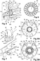
figure 6 est une section selon la ligne VI-VI de lafigure 5 - La
figure 7 est une vue en perspective d'une partie supérieure d'un échangeur thermique équipé d'un système de régulation qui illustre un mode de réalisation de l'invention, - Les
figures 8A et 8B sont des vues de dessus du système de régulation visible sur lafigure 7 respectivement à l'état fermé et à l'état totalement ouvert. - Sur la
figure 3 , on a représenté un ensemble moteur 52 qui comprend : - un moteur 54 comportant une zone appelée zone « core » dans le langage aéronautique (ou coeur en français), dans laquelle circule un flux primaire d'air,
- une nacelle 56 positionnée autour du moteur 54 de manière à délimiter avec ce dernier un conduit annulaire dans lequel s'écoule un flux secondaire 55 d'air froid, et
- un mât 58 qui assure la liaison entre le moteur 56 et une voilure d'un aéronef.
- Le moteur 54 comprend, selon le sens d'écoulement du flux primaire matérialisé par la flèche 59, un carter de soufflante 54.1 de grande dimension délimitant un canal annulaire de soufflante, un carter central 54.2 de plus petite dimension renfermant la zone « core » du moteur 54 traversé par le flux primaire, et un carter d'éjection 54.3 de plus grande dimension via lequel est éjecté le flux primaire.
- Le mât 58 comprend une structure primaire 60 rigide, qui assure entre autres la transmission des efforts entre le moteur 54 et le reste de l'aéronef, et une structure secondaire 62, qui supporte au moins un carénage, qui enveloppe la structure primaire 60 à l'extérieur de la nacelle 56 et qui limite la traînée du mât 58.
- Entre le moteur 54 et la nacelle 56, la structure primaire 60 du mât est positionnée dans une bifurcation 64 (représentés transparente sur la
figure 4 ) qui présente un carénage aérodynamique enveloppant la structure primaire 60 dans le flux secondaire 55 afin de réduire les perturbations sur le flux secondaire 55. - Tous ces éléments de l'ensemble moteur ne sont pas plus décrits car ils peuvent être identiques à ceux de l'art antérieur.
- Pour la suite de la description, les termes avant et arrière font référence au sens d'écoulement des flux d'air à l'intérieur du moteur 54 qui pénètrent à l'avant Av du moteur 54 et qui sortent à l'arrière Ar du moteur 54.
- Au moins un ensemble moteur 52 comprend au moins un dispositif d'échange thermique 66 configuré pour refroidir de l'air chaud prélevé au niveau des étages de compression du moteur 54 et destiné aux systèmes de climatisation et de pressurisation de l'aéronef, de dégivrage de la voilure et/ou à tout autre système de l'aéronef.
- Selon un mode de réalisation visible sur les
figures 3 à 5 et7 , chaque dispositif d'échange thermique 66 comprend un échangeur thermique 68 qui a une forme tubulaire, qui traverse la structure primaire 60 du mât et qui est positionné au moins partiellement à l'intérieur de la structure primaire 60 du mât. - Selon une configuration privilégiée, la forme tubulaire de l'échangeur thermique 68 présente un axe A68 orienté approximativement à la verticale. En variante, l'axe A68 peut être positionné dans un plan passant par l'axe moteur et vertical, appelé par la suite plan médian vertical PMV, et être plus ou moins incliné vers l'avant ou vers l'arrière.
- L'échangeur thermique 68 comprend un premier tronçon de circuit 70 d'air chaud et un deuxième tronçon de circuit 72 d'air froid, les premier et deuxième tronçons de circuit 70 et 72 étant coaxiaux et séparés par au moins une cloison 74 favorisant les échanges thermiques, notamment par conduction, entre l'air chaud circulant dans le premier tronçon de circuit 70 et l'air froid circulant dans le deuxième tronçon de circuit 72.
- Selon une configuration, le premier tronçon de circuit 70 est positionné à l'intérieur du deuxième tronçon de circuit 72. Ainsi, l'air froid canalisé à l'extérieur du premier tronçon de circuit 70, dans le deuxième tronçon de circuit 72, forme une barrière thermique protégeant la structure primaire 60 des températures élevées de l'air chaud.
- Selon un mode de réalisation visible sur la
figure 6 , le deuxième tronçon de circuit 72 est cylindrique et coaxial à l'axe A68. Le premier tronçon de circuit 70 a une section, dans un plan perpendiculaire à l'axe A68, étoilée pour augmenter la surface d'échange de la cloison 74. Bien entendu, l'invention n'est pas limitée à ce mode de réalisation pour la section du premier tronçon de circuit 70. En complément ou en alternative, la cloison 74 présente des surfaces d'échange additionnelles, comme des ailettes par exemple. - Selon un mode de réalisation, la cloison 74 est réalisée en un matériau favorisant les échanges thermiques, comme par exemple en matériau céramique.
- Le matériau de la cloison 74, la géométrie de sa section et les formes en surface de la cloison 74 sont déterminés de manière à favoriser les échanges thermiques entre les flux d'air chaud et froid et réduire les dimensions de l'échangeur thermique 68.
- Comme illustré en détails sur la
figure 5 , le premier tronçon de circuit 70 comprend une première entrée 70.1 et une première sortie 70.2 positionnée au-dessus de la première entrée 70.1, le flux d'air chaud circulant, vers le haut, de la première entrée 70.1 vers la première sortie 70.2. - Selon une configuration, la première entrée 70.1 est positionnée au-dessous de la structure primaire 60 du mât et la première sortie 70.2 est positionnée au-dessus de la structure primaire 60 du mât.
- Le dispositif d'échange thermique 66 comprend également un premier conduit 76 qui présente une première extrémité connectée à la première entrée 70.1, configuré pour prélever l'air chaud au niveau du moteur 54, plus particulièrement dans la zone « core » du moteur positionné dans le carter central 54.2; ainsi qu'un deuxième conduit 78 qui présente une première extrémité connectée à la première sortie 70.2, configuré pour acheminer l'air chaud refroidi vers au moins un équipement de l'aéronef utilisant de l'air chaud.
- Selon une configuration, le premier conduit 76 présente, au niveau de sa première extrémité connectée à la première entrée 70.1, un premier coude 76.1 qui oriente le reste du premier conduit 76 vers l'avant. Le deuxième conduit 78 présente, au niveau de sa première extrémité connectée à la première sortie 70.2, un deuxième coude 78.1 qui oriente le reste du deuxième conduit 78 vers l'arrière.
- Le deuxième tronçon de circuit 72 comprend une deuxième entrée 72.1 et une deuxième sortie 72.2, le flux d'air froid circulant de la deuxième entrée 72.1 vers la deuxième sortie 72.2.
- Selon une caractéristique de l'invention, le flux d'air chaud circulant dans le premier tronçon de circuit 70 s'écoule à contre sens par rapport au flux d'air froid circulant dans le deuxième tronçon de circuit 72 pour améliorer les échanges thermiques entre les flux d'air chaud et froid.
- Ainsi, la deuxième entrée 72.1 est positionnée au-dessus de la structure primaire 60 du mât et la deuxième sortie 72.2 est positionnée au-dessous de la structure primaire 60 du mât.
- Selon un mode de réalisation, la première entrée 70.1 et la deuxième sortie 72.2 sont positionnées dans un même plan P1 perpendiculaire à l'axe A68 et positionné au-dessous de la structure primaire 60 du mât. La première sortie 70.2 et la deuxième entrée 72.1 sont positionnées dans un même plan P2 perpendiculaire à l'axe A68 et positionné au-dessus de la structure primaire 60 du mât.
- Selon un mode de réalisation, l'échangeur thermique 68 se présente sous la forme d'un cylindre, compact, qui s'étend entre les plans P1 et P2.
- Le dispositif d'échange thermique 66 comprend également un troisième conduit 80 qui présente une première extrémité connectée à la deuxième entrée 72.1, configuré pour prélever l'air froid dans le flux secondaire 55 ; ainsi qu'un quatrième conduit 82 qui présente une première extrémité connecté à la deuxième sortie 72.2, configuré pour refouler l'air froid dans le moteur 54, plus particulièrement vers la zone « core » du moteur 54 positionné dans le carter central 54.2.
- Selon une configuration, le troisième conduit 80 comporte au niveau de sa deuxième extrémité une écope 84 qui présente une ouverture orientée vers l'avant pour qu'une partie du flux secondaire 55 pénètre naturellement dans l'écope 84. Le troisième conduit 80 présente, au niveau de sa première extrémité connectée à la deuxième entrée 72.1, un troisième coude 80.1 qui oriente le reste du troisième conduit 80 vers l'avant.
- Comme illustré sur la
figure 5 , le deuxième conduit 78 traverse la paroi du troisième conduit 80 au niveau du rayon extérieur du coude 80.1 du troisième conduit 80. - Selon un mode de réalisation, l'écope 84 est positionnée au niveau du bord d'attaque de la bifurcation 64, au-dessus de la structure primaire 60.
- Selon une configuration, le quatrième conduit 82 comporte au niveau de sa deuxième extrémité un orifice d'échappement 86 orienté vers l'arrière permettant d'orienter le flux d'air froid refoulé selon l'axe moteur afin qu'il contribue à la poussée du moteur 54. Le quatrième conduit 82 présente, au niveau de sa première extrémité connectée à la deuxième sortie 72.2, un quatrième coude 82.1 qui oriente le reste du quatrième conduit 82 vers l'arrière. Comme illustré sur la
figure 5 , le premier conduit 76 traverse la paroi du quatrième conduit 82 au niveau du rayon extérieur du coude 82.1 du quatrième conduit 82. - Selon un mode de réalisation, l'orifice d'échappement 86 est positionné au-dessous de la structure primaire 60.
- Contrairement à l'art antérieur, le flux d'air froid est aspiré, via l'écope 84, au-dessus de la structure primaire 60 et refoulé, via l'orifice d'échappement 86, au-dessous de la structure primaire 60 ce qui permet d'obtenir, dans l'échangeur thermique 68, un flux d'air froid à contre-courant par rapport au flux d'air chaud.
- Cependant, l'invention n'est pas limitée à ce mode de réalisation. Ainsi, les flux d'air chaud et froid peuvent circuler dans le même sens, le flux d'air froid étant aspiré au-dessous de la structure primaire 60 et refoulé au-dessus de la structure primaire 60.
- Selon une autre caractéristique de l'invention, l'échangeur thermique 68 comprend un système de fixation 88 pour le relier à la structure primaire 60. Ainsi, contrairement à l'art antérieur, l'échangeur thermique 68 n'est pas supporté par la structure secondaire 62. Dès lors, la conception de cette structure secondaire 62 peut être simplifiée.
- Selon un mode de réalisation visible sur la
figure 7 , le système de fixation 88 comprend une collerette extérieure 90 solidaire du deuxième tronçon de circuit 72, qui est configurée pour être plaquée contre une face supérieure de la structure primaire 60 ; ainsi que des fixations 92, comme par exemple des vis, pour solidariser ladite collerette extérieure 90 à la structure primaire 60. Bien entendu, l'invention n'est pas limitée à ce système de fixation pour relier l'échangeur thermique 68 à la structure primaire 60 du mât. - Le dispositif d'échange thermique 66 comprend un système de régulation 94 configuré pour ajuster le débit du flux d'air froid.
- Selon une configuration, le système de régulation 94 est configuré pour ajuster le débit de l'air froid circulant entre le deuxième tronçon de circuit 72 et le premier tronçon de circuit 70.
- Pour obtenir un dispositif d'échange thermique 66 compact, le système de régulation 94 est un système de régulation à diaphragme. Le système de régulation 94 est positionné au niveau du plan P2, soit au niveau de la deuxième entrée 72.1 du deuxième tronçon de circuit 72.
- Le système de régulation 94 est configuré pour occuper :
- un état fermé, visible sur la
figure 8A , dans lequel il obture totalement le deuxième tronçon de circuit 72, empêchant l'écoulement du flux d'air froid, - un état totalement ouvert, visible sur la
figure 8B , dans lequel il dégage totalement le deuxième tronçon de circuit 72, autorisant l'écoulement du flux d'air froid à un débit maximal, et de préférence - au moins un état intermédiaire dans lequel il dégage partiellement le deuxième tronçon de circuit 72, autorisant l'écoulement du flux d'air froid à un débit plus ou moins important.
- Le dispositif d'échange thermique 66 comprend une commande (non représentée) pour contrôler l'état du système de régulation 94.
- Selon un mode de réalisation visible sur les
figures 8A et 8B , le système de régulation 94 comprend une couronne 95, coaxiale à l'axe A68, et au moins deux secteurs de disque 96 mobiles par rapport à la couronne 95, selon une direction de déplacement, les secteurs de disque 96 étant configurés pour occuper : - une position la plus rapprochée de l'axe A68, visible sur la
figure 8A , dans laquelle les secteurs de disque 96 sont jointifs et obturent le deuxième tronçon de circuit 72 ce qui correspond à l'état fermé, - une position la plus écartée de l'axe A68, visible sur la
figure 8B , dans laquelle les secteurs de disque 96 sont espacés et dégagent totalement le deuxième tronçon de circuit 72 ce qui correspond à l'état ouvert, et de préférence, - une position intermédiaire, entre les positions la plus rapprochée et la plus écartée, qui correspond à un des états intermédiaires.
- Le mode de réalisation visible sur les
figures 8A et 8B comprend six secteurs de disque 96 régulièrement répartis autour de l'axe A68, s'étendant chacun sur un secteur angulaire de l'ordre de 60°. - Le système de régulation 94 comprend pour chaque secteur de disque 96, un système de guidage 98 configuré pour guider chaque secteur de disque 96 selon la direction radiale. Selon un mode de réalisation, le système de guidage 98 comprend, sur chaque secteur de disque 96, une lumière oblongue 100 orientée selon la direction de déplacement et, sur la couronne 95, des pions 102, un pour chaque secteur de disque 96, configuré pour se loger dans une des lumières oblongues 100. En variante, comme illustré sur les
figures 8A et 8B , le système de guidage 98 comprend, sur la couronne 95, une lumière oblongue 100 orientée selon la direction de déplacement pour chaque secteur de disque 96 et, sur chaque secteur de disque 96, un pion 102 configuré pour se loger dans une des lumières oblongues 100.
Selon une première configuration, la direction de déplacement est radiale (perpendiculaire à l'axe A68) et les lumières oblongues 100 sont orientées radialement. Dans ce cas, la couronne 95 est fixe et le système de régulation 94 comprend une deuxième couronne mobile configurée pour pivoter autour de l'axe A68 et reliée aux secteurs de disque 96 de sorte que le pivotement de la deuxième couronne provoque un déplacement radial des secteurs de disque 96. - Selon une deuxième configuration, la direction de déplacement n'est pas radiale et les lumières oblongues 100 sont orientées selon une direction formant un angle non nul avec la direction radiale. Dans ce cas, la couronne 95 est mobile, le pivotement de la couronne 95 autour de l'axe A68 provoquant un déplacement radial des secteurs de disque 96. Bien entendu, l'invention n'est pas limitée à ces modes de réalisation pour le système de régulation 94.
- Le dispositif d'échange thermique 66 de l'invention procure les avantages suivants :
Le fait de prévoir un échangeur thermique 68 de type coaxial, sensiblement tubulaire, permet de pouvoir le placer, au moins partiellement, dans la structure primaire 60 (à la manière du conduit d'alimentation en air chaud de l'art antérieur). Ainsi, l'impact de son intégration sur les formes aérodynamiques du carénage de la structure secondaire 62 est limité. - En raison du positionnement de l'échangeur thermique 68 dans la structure primaire 60, le carénage de la structure secondaire 62 peut être positionné au plus près de la structure primaire et/ou l'espace dégagé entre la structure secondaire et la structure primaire peut être utilisé pour intégrer d'autres équipements.
- Par ailleurs, le flux d'air froid étant rejeté dans la zone « core » du moteur 54, il contribue à augmenter la poussée du moteur.
- Enfin, le dispositif d'échange thermique étant relié à la structure primaire 60 et non à la structure secondaire 62, la conception de cette dernière s'en trouve simplifiée.
Claims (10)
- Mât d'aéronef comprenant :- Une structure primaire (60) configurée pour relier un moteur (54) d'aéronef et une voilure,- Une structure secondaire (62) comportant un carénage aérodynamique configuré pour envelopper la structure primaire (60) à l'extérieur d'une nacelle (56) entourant le moteur (54),- Une bifurcation (64) comportant un carénage aérodynamique configuré pour envelopper la structure primaire (60) dans un flux secondaire (55) canalisé entre la nacelle (56) et le moteur (54),- Un dispositif d'échange thermique (66) comportant :les premier et deuxième tronçons de circuit (70, 72) de l'échangeur thermique (68) étant coaxiaux, caractérisé en ce que les premier et deuxième tronçons de circuit (70, 72) sont séparés par au moins une cloison (74) formant une surface d'échange, et positionnés, au moins partiellement, dans la structure primaire (60) du mât, ladite cloison (74) étant en un matériau favorisant des échanges thermiques, le premier tronçon de circuit (70) ayant une section avec une géométrie augmentant la surface d'échange de la cloison (74) et/ou la cloison (74) présentant des surfaces d'échange additionnelles.∘ un échangeur thermique (68) qui comprend un premier tronçon de circuit (70) canalisant un flux d'air chaud qui présente une première entrée (70.1) et une première sortie (70.2), ainsi qu'un deuxième tronçon de circuit (72) canalisant un flux d'air froid qui présente une deuxième entrée (72.1) et une deuxième sortie (72.2),∘ un premier conduit (76) ayant une première extrémité connectée à la première entrée (70.1), configuré pour prélever le flux d'air chaud au niveau du moteur (54),∘ un deuxième conduit (78), ayant une première extrémité connectée à la première sortie (70.2), configuré pour acheminer le flux d'air chaud refroidi vers au moins un équipement de l'aéronef,
- Mât d'aéronef selon la revendication 1, caractérisé en ce que le premier tronçon de circuit (70) canalisant l'air chaud est positionné à l'intérieur du deuxième tronçon de circuit (72) canalisant l'air froid.
- Mât d'aéronef selon l'une des revendications précédentes, caractérisé en ce que la première entrée (70.1) et la première sortie (70.2) sont positionnées respectivement au-dessous et au-dessus de la structure primaire (60) du mât, et en ce que la deuxième entrée (72.1) et la deuxième sortie (72.2) sont positionnées respectivement au-dessus et au-dessous de la structure primaire (60) du mât pour que le flux d'air chaud circulant dans le premier tronçon de circuit (70) s'écoule à contre sens par rapport au flux d'air froid circulant dans le deuxième tronçon de circuit (72).
- Mât d'aéronef selon l'une des revendications précédentes, caractérisé en ce que le dispositif d'échange thermique (66) comprend un troisième conduit (80) qui présente une première extrémité connectée à la deuxième entrée (72.1) et, au niveau d'une deuxième extrémité, une écope (84) ouverte vers l'avant pour qu'une partie du flux secondaire (55) pénètre naturellement dans l'écope (84) ainsi qu'un quatrième conduit (82) qui présente une première extrémité connectée à la deuxième sortie (72.2), configuré pour refouler l'air froid dans le moteur (54).
- Mât d'aéronef selon la revendication précédente, caractérisé en ce que l'écope (84) est positionnée au niveau d'un bord d'attaque de la bifurcation (64), au-dessus de la structure primaire (60).
- Mât d'aéronef selon la revendication 4 ou 5, caractérisé en ce que le premier conduit (76) présente, au niveau de sa première extrémité connectée à la première entrée (70.1) de l'échangeur thermique (68), un premier coude (76.1) qui oriente le reste du premier conduit (76) vers l'avant, en ce que le deuxième conduit (78) présente, au niveau de sa première extrémité connectée à la première sortie (70.2) de l'échangeur thermique (68), un deuxième coude (78.1) qui oriente le reste du deuxième conduit (78) vers l'arrière, en ce que le troisième conduit (80) présente, au niveau de sa première extrémité connectée à la deuxième entrée (72.1) de l'échangeur thermique (68), un troisième coude (80.1) qui oriente le reste du troisième conduit (80) vers l'avant, le deuxième conduit (78) traversant la paroi du troisième conduit (80) au niveau du rayon extérieur du troisième coude (80.1) et en ce que le quatrième conduit (82) présente, au niveau de sa première extrémité connectée à la deuxième sortie (72.2) de l'échangeur thermique (68), un quatrième coude (82.1) qui oriente le reste du quatrième conduit (82) vers l'arrière, le premier conduit (76) traversant la paroi du quatrième conduit (84) au niveau du rayon extérieur du quatrième coude (82.1).
- Mât d'aéronef selon l'une des revendications précédentes, caractérisé en ce que l'échangeur thermique (68) comprend un système de fixation (88) pour le relier à la structure primaire (60).
- Mât d'aéronef selon l'une des revendications précédentes, caractérisé en ce que le dispositif d'échange thermique (66) comprend un système de régulation (94) à diaphragme configuré pour ajuster le débit du flux d'air froid.
- Mât d'aéronef selon la revendication précédente, caractérisé en ce que le système de régulation (94) comprend une couronne (95), coaxiale à un axe (A68) de l'échangeur thermique, et au moins deux secteurs de disque (96) mobiles par rapport à la couronne (95), les secteurs de disque (96) étant configurés pour occuper :- une position la plus rapprochée de l'axe (A68), dans laquelle les secteurs de disque (96) sont jointifs et obturent le deuxième tronçon de circuit (72), empêchant l'écoulement du flux d'air froid,- une position la plus écartée de l'axe (A68), dans laquelle les secteurs de disque (96) sont espacés et dégagent totalement le deuxième tronçon de circuit (72), autorisant l'écoulement du flux d'air froid à un débit maximal, et de préférence,- une position intermédiaire, entre les positions la plus rapprochée et la plus écartée, autorisant l'écoulement du flux d'air froid à un débit plus ou moins important.
- Aéronef comprenant un mât selon l'une des revendications précédentes.
Applications Claiming Priority (1)
| Application Number | Priority Date | Filing Date | Title |
|---|---|---|---|
| FR1850565A FR3077060A1 (fr) | 2018-01-24 | 2018-01-24 | Mat d'aeronef comprenant un echangeur thermique coaxial |
Publications (2)
| Publication Number | Publication Date |
|---|---|
| EP3517444A1 true EP3517444A1 (fr) | 2019-07-31 |
| EP3517444B1 EP3517444B1 (fr) | 2020-05-13 |
Family
ID=61521769
Family Applications (1)
| Application Number | Title | Priority Date | Filing Date |
|---|---|---|---|
| EP18212157.4A Active EP3517444B1 (fr) | 2018-01-24 | 2018-12-13 | Mât d'aeronef comprenant un echangeur thermique coaxial |
Country Status (3)
| Country | Link |
|---|---|
| US (1) | US11408337B2 (fr) |
| EP (1) | EP3517444B1 (fr) |
| FR (1) | FR3077060A1 (fr) |
Families Citing this family (5)
| Publication number | Priority date | Publication date | Assignee | Title |
|---|---|---|---|---|
| FR3070967B1 (fr) * | 2017-09-14 | 2019-08-30 | Airbus Operations | Dispositif d'echange thermique compact incorpore dans un mat d'aeronef |
| DE102020006235A1 (de) | 2020-10-09 | 2022-04-14 | Airbus Defence and Space GmbH | Luftleitanordnung für ein Luftfahrzeug mit integriertem Wärmetauscher |
| CN113982717B (zh) * | 2021-09-01 | 2023-11-14 | 江苏江航智飞机发动机部件研究院有限公司 | 一种直升机发动机的加速冷却滑油管 |
| FR3128443A1 (fr) | 2021-10-25 | 2023-04-28 | Airbus Operations (S.A.S.) | Ensemble de propulsion d’aéronef comprenant un échangeur thermique à plaques, de section longitudinale hexagonale, positionné dans une bifurcation |
| FR3132082A1 (fr) * | 2022-01-26 | 2023-07-28 | Airbus Operations | Ensemble pour aéronef comportant un mât et un échangeur thermique fixé sur le mât par l’intermédiaire d’un module support |
Citations (4)
| Publication number | Priority date | Publication date | Assignee | Title |
|---|---|---|---|---|
| FR2734319A1 (fr) * | 1995-05-15 | 1996-11-22 | Aerospatiale | Dispositif pour prelever et refroidir de l'air chaud au niveau d'un moteur d'aeronef |
| EP1365203A1 (fr) * | 2002-05-22 | 2003-11-26 | Airbus France | Echangeur pour circuit de conditionnement d'air d'aéronef et ensemble de propulsion integrant un tel échangeur |
| WO2007012725A2 (fr) | 2005-07-28 | 2007-02-01 | Airbus France | Echangeur thermique, ensemble propulseur et aeronef comportant un tel ensemble propulseur |
| WO2018002855A1 (fr) * | 2016-06-30 | 2018-01-04 | Bombardier Inc. | Ensemble et procédé de conditionnement d'air chauffé par moteur à bord d'un aéronef |
Family Cites Families (14)
| Publication number | Priority date | Publication date | Assignee | Title |
|---|---|---|---|---|
| US3201938A (en) * | 1963-06-27 | 1965-08-24 | Gen Electric | Recuperative arrangement for gas turbine engines |
| US6134880A (en) * | 1997-12-31 | 2000-10-24 | Concepts Eti, Inc. | Turbine engine with intercooler in bypass air passage |
| FR2889297B1 (fr) * | 2005-07-28 | 2010-11-26 | Airbus France | Echangeur thermique, ensemble propulseur, et aeronef comportant un tel ensemble propulseur |
| US7607308B2 (en) * | 2005-12-08 | 2009-10-27 | General Electric Company | Shrouded turbofan bleed duct |
| US7856824B2 (en) * | 2007-06-25 | 2010-12-28 | Honeywell International Inc. | Cooling systems for use on aircraft |
| US8826641B2 (en) * | 2008-01-28 | 2014-09-09 | United Technologies Corporation | Thermal management system integrated pylon |
| US8024935B2 (en) * | 2008-11-21 | 2011-09-27 | Honeywell International Inc. | Flush inlet scoop design for aircraft bleed air system |
| WO2014051678A1 (fr) * | 2012-09-28 | 2014-04-03 | United Technologies Corporation | Système de gestion thermique de moteur à turbine à gaz pour échangeur thermique utilisant un écoulement dérivé |
| US11268526B2 (en) * | 2013-07-09 | 2022-03-08 | Raytheon Technologies Corporation | Plated polymer fan |
| JP6450076B2 (ja) * | 2014-02-24 | 2019-01-09 | 三菱航空機株式会社 | 航空機、航空機のエンジンパイロン、および航空機の機体へのエンジン取付方法 |
| EP3666655B1 (fr) * | 2018-12-14 | 2021-07-14 | Airbus Operations (S.A.S.) | Système de propulsion d'avion comprenant un système d'échangeur thermique |
| US20200300164A1 (en) * | 2019-03-22 | 2020-09-24 | United Technologies Corporation | Turbine engine configuration including pylon mounted heat exchanger |
| GB202001220D0 (en) * | 2020-01-29 | 2020-03-11 | Vertical Aerospace Ltd | Propulsion system thermal management |
| WO2022031791A1 (fr) * | 2020-08-04 | 2022-02-10 | Micropen Technologies Corporation | Ensembles conduit de fluide et systèmes de transport de fluide |
-
2018
- 2018-01-24 FR FR1850565A patent/FR3077060A1/fr not_active Withdrawn
- 2018-12-13 EP EP18212157.4A patent/EP3517444B1/fr active Active
-
2019
- 2019-01-22 US US16/253,548 patent/US11408337B2/en active Active
Patent Citations (4)
| Publication number | Priority date | Publication date | Assignee | Title |
|---|---|---|---|---|
| FR2734319A1 (fr) * | 1995-05-15 | 1996-11-22 | Aerospatiale | Dispositif pour prelever et refroidir de l'air chaud au niveau d'un moteur d'aeronef |
| EP1365203A1 (fr) * | 2002-05-22 | 2003-11-26 | Airbus France | Echangeur pour circuit de conditionnement d'air d'aéronef et ensemble de propulsion integrant un tel échangeur |
| WO2007012725A2 (fr) | 2005-07-28 | 2007-02-01 | Airbus France | Echangeur thermique, ensemble propulseur et aeronef comportant un tel ensemble propulseur |
| WO2018002855A1 (fr) * | 2016-06-30 | 2018-01-04 | Bombardier Inc. | Ensemble et procédé de conditionnement d'air chauffé par moteur à bord d'un aéronef |
Non-Patent Citations (1)
| Title |
|---|
| EL MAAKOUL ANAS ET AL: "Numerical investigation of thermohydraulic performance of air to water double-pipe heat exchanger with helical fins", APPLIED THERMAL ENGINEERING, PERGAMON, OXFORD, GB, vol. 127, 7 August 2017 (2017-08-07), pages 127 - 139, XP085209061, ISSN: 1359-4311, DOI: 10.1016/J.APPLTHERMALENG.2017.08.024 * |
Also Published As
| Publication number | Publication date |
|---|---|
| EP3517444B1 (fr) | 2020-05-13 |
| US20190226400A1 (en) | 2019-07-25 |
| FR3077060A1 (fr) | 2019-07-26 |
| US11408337B2 (en) | 2022-08-09 |
Similar Documents
| Publication | Publication Date | Title |
|---|---|---|
| EP3517444B1 (fr) | Mât d'aeronef comprenant un echangeur thermique coaxial | |
| EP1973779B1 (fr) | Turbomoteur à double flux pourvu d'un prérefroidisseur | |
| EP1928737B1 (fr) | Turbomoteur a double flux pourvu d`un prerefroidisseur | |
| EP2986507B1 (fr) | Nacelle pour turboréacteur d'aéronef à lèvre avant étendue | |
| CA2615273C (fr) | Ensemble propulseur pour aeronef et aeronef comportant au moins un tel ensemble propulseur | |
| CA2631849C (fr) | Turbomoteur a double flux pourvu d'un prerefroidisseur | |
| CA2328555C (fr) | Dispositif d'evacuation d'air chaud pour capot d'entree d'air de moteur a reaction, a circuit de degivrage | |
| EP2212538B1 (fr) | Procédé pour améliorer les performances d'un turbomoteur à double flux | |
| FR2917714A1 (fr) | Turboreacteur pour aeronef | |
| FR3070967A1 (fr) | Dispositif d'echange thermique compact incorpore dans un mat d'aeronef | |
| EP2171218B1 (fr) | Turbomoteur a double flux et tuyere de flux chaud perfectionnee | |
| EP3891374B1 (fr) | Inverseur de poussée muni d'un volet d'inversion de poussée allégé | |
| EP3775516B1 (fr) | Dispositif de ventilation pour vehicule automobile | |
| FR2921977A1 (fr) | Turbomoteur a double flux pour aeronef | |
| EP4077903B1 (fr) | Inverseur de poussée avec système d'actionnement anti-flambage | |
| FR3018863A1 (fr) | Dispositif d'inversion de poussee sans grille pour nacelle de turboreacteur d'aeronef | |
| FR3100269A1 (fr) | Systeme propulsif pour un aeronef, ledit systeme propulsif comportant un systeme d’echangeur thermique | |
| EP4323631B1 (fr) | Inverseur de poussee a grilles mobiles comprenant une structure fixe plurifonctionnelle | |
| FR3080889A1 (fr) | Ensemble propulsif pour aeronef comprenant un dispositif de prise d'air froid a profil aerodynamique variable | |
| EP4085190B1 (fr) | Inverseur de poussée à portes comprenant un déflecteur pour rediriger un flux d'air vers l'amont | |
| FR2991013A1 (fr) | Ventilateur pour automobile avec deflecteur aerodynamique | |
| WO2021136900A1 (fr) | Inverseur de poussée à portes comprenant un déflecteur pour rediriger un flux d'air vers un empennage | |
| EP3778383A1 (fr) | Partie antérieure de nacelle d'un ensemble propulsif d'aéronef comportant une zone de transition thermique | |
| FR2993921A1 (fr) | Procede pour ameliorer les performances du systeme d'ejection d'un turbomoteur d'aeronef a double flux separes, systeme d'ejection et turbomoteur correspondants. | |
| FR2863948A1 (fr) | Dispositif de chauffage/desembuage d'un vehicule |
Legal Events
| Date | Code | Title | Description |
|---|---|---|---|
| STAA | Information on the status of an ep patent application or granted ep patent |
Free format text: STATUS: EXAMINATION IS IN PROGRESS |
|
| PUAI | Public reference made under article 153(3) epc to a published international application that has entered the european phase |
Free format text: ORIGINAL CODE: 0009012 |
|
| 17P | Request for examination filed |
Effective date: 20181213 |
|
| AK | Designated contracting states |
Kind code of ref document: A1 Designated state(s): AL AT BE BG CH CY CZ DE DK EE ES FI FR GB GR HR HU IE IS IT LI LT LU LV MC MK MT NL NO PL PT RO RS SE SI SK SM TR |
|
| AX | Request for extension of the european patent |
Extension state: BA ME |
|
| GRAP | Despatch of communication of intention to grant a patent |
Free format text: ORIGINAL CODE: EPIDOSNIGR1 |
|
| STAA | Information on the status of an ep patent application or granted ep patent |
Free format text: STATUS: GRANT OF PATENT IS INTENDED |
|
| INTG | Intention to grant announced |
Effective date: 20191213 |
|
| GRAS | Grant fee paid |
Free format text: ORIGINAL CODE: EPIDOSNIGR3 |
|
| RBV | Designated contracting states (corrected) |
Designated state(s): AL AT BE BG CH CY CZ DE DK EE ES FI FR GB GR HR HU IE IS IT LI LT LU LV MC MK MT NL NO PL PT RO RS SE SI SK SM TR |
|
| GRAA | (expected) grant |
Free format text: ORIGINAL CODE: 0009210 |
|
| STAA | Information on the status of an ep patent application or granted ep patent |
Free format text: STATUS: THE PATENT HAS BEEN GRANTED |
|
| AK | Designated contracting states |
Kind code of ref document: B1 Designated state(s): AL AT BE BG CH CY CZ DE DK EE ES FI FR GB GR HR HU IE IS IT LI LT LU LV MC MK MT NL NO PL PT RO RS SE SI SK SM TR |
|
| REG | Reference to a national code |
Ref country code: GB Ref legal event code: FG4D Free format text: NOT ENGLISH |
|
| REG | Reference to a national code |
Ref country code: CH Ref legal event code: EP |
|
| REG | Reference to a national code |
Ref country code: DE Ref legal event code: R096 Ref document number: 602018004641 Country of ref document: DE |
|
| REG | Reference to a national code |
Ref country code: AT Ref legal event code: REF Ref document number: 1269957 Country of ref document: AT Kind code of ref document: T Effective date: 20200615 |
|
| REG | Reference to a national code |
Ref country code: LT Ref legal event code: MG4D |
|
| REG | Reference to a national code |
Ref country code: NL Ref legal event code: MP Effective date: 20200513 |
|
| PG25 | Lapsed in a contracting state [announced via postgrant information from national office to epo] |
Ref country code: NO Free format text: LAPSE BECAUSE OF FAILURE TO SUBMIT A TRANSLATION OF THE DESCRIPTION OR TO PAY THE FEE WITHIN THE PRESCRIBED TIME-LIMIT Effective date: 20200813 Ref country code: IS Free format text: LAPSE BECAUSE OF FAILURE TO SUBMIT A TRANSLATION OF THE DESCRIPTION OR TO PAY THE FEE WITHIN THE PRESCRIBED TIME-LIMIT Effective date: 20200913 Ref country code: SE Free format text: LAPSE BECAUSE OF FAILURE TO SUBMIT A TRANSLATION OF THE DESCRIPTION OR TO PAY THE FEE WITHIN THE PRESCRIBED TIME-LIMIT Effective date: 20200513 Ref country code: GR Free format text: LAPSE BECAUSE OF FAILURE TO SUBMIT A TRANSLATION OF THE DESCRIPTION OR TO PAY THE FEE WITHIN THE PRESCRIBED TIME-LIMIT Effective date: 20200814 Ref country code: FI Free format text: LAPSE BECAUSE OF FAILURE TO SUBMIT A TRANSLATION OF THE DESCRIPTION OR TO PAY THE FEE WITHIN THE PRESCRIBED TIME-LIMIT Effective date: 20200513 Ref country code: LT Free format text: LAPSE BECAUSE OF FAILURE TO SUBMIT A TRANSLATION OF THE DESCRIPTION OR TO PAY THE FEE WITHIN THE PRESCRIBED TIME-LIMIT Effective date: 20200513 Ref country code: PT Free format text: LAPSE BECAUSE OF FAILURE TO SUBMIT A TRANSLATION OF THE DESCRIPTION OR TO PAY THE FEE WITHIN THE PRESCRIBED TIME-LIMIT Effective date: 20200914 |
|
| PG25 | Lapsed in a contracting state [announced via postgrant information from national office to epo] |
Ref country code: LV Free format text: LAPSE BECAUSE OF FAILURE TO SUBMIT A TRANSLATION OF THE DESCRIPTION OR TO PAY THE FEE WITHIN THE PRESCRIBED TIME-LIMIT Effective date: 20200513 Ref country code: HR Free format text: LAPSE BECAUSE OF FAILURE TO SUBMIT A TRANSLATION OF THE DESCRIPTION OR TO PAY THE FEE WITHIN THE PRESCRIBED TIME-LIMIT Effective date: 20200513 Ref country code: RS Free format text: LAPSE BECAUSE OF FAILURE TO SUBMIT A TRANSLATION OF THE DESCRIPTION OR TO PAY THE FEE WITHIN THE PRESCRIBED TIME-LIMIT Effective date: 20200513 Ref country code: BG Free format text: LAPSE BECAUSE OF FAILURE TO SUBMIT A TRANSLATION OF THE DESCRIPTION OR TO PAY THE FEE WITHIN THE PRESCRIBED TIME-LIMIT Effective date: 20200813 |
|
| REG | Reference to a national code |
Ref country code: AT Ref legal event code: MK05 Ref document number: 1269957 Country of ref document: AT Kind code of ref document: T Effective date: 20200513 |
|
| PG25 | Lapsed in a contracting state [announced via postgrant information from national office to epo] |
Ref country code: NL Free format text: LAPSE BECAUSE OF FAILURE TO SUBMIT A TRANSLATION OF THE DESCRIPTION OR TO PAY THE FEE WITHIN THE PRESCRIBED TIME-LIMIT Effective date: 20200513 Ref country code: AL Free format text: LAPSE BECAUSE OF FAILURE TO SUBMIT A TRANSLATION OF THE DESCRIPTION OR TO PAY THE FEE WITHIN THE PRESCRIBED TIME-LIMIT Effective date: 20200513 |
|
| PG25 | Lapsed in a contracting state [announced via postgrant information from national office to epo] |
Ref country code: IT Free format text: LAPSE BECAUSE OF FAILURE TO SUBMIT A TRANSLATION OF THE DESCRIPTION OR TO PAY THE FEE WITHIN THE PRESCRIBED TIME-LIMIT Effective date: 20200513 Ref country code: CZ Free format text: LAPSE BECAUSE OF FAILURE TO SUBMIT A TRANSLATION OF THE DESCRIPTION OR TO PAY THE FEE WITHIN THE PRESCRIBED TIME-LIMIT Effective date: 20200513 Ref country code: RO Free format text: LAPSE BECAUSE OF FAILURE TO SUBMIT A TRANSLATION OF THE DESCRIPTION OR TO PAY THE FEE WITHIN THE PRESCRIBED TIME-LIMIT Effective date: 20200513 Ref country code: ES Free format text: LAPSE BECAUSE OF FAILURE TO SUBMIT A TRANSLATION OF THE DESCRIPTION OR TO PAY THE FEE WITHIN THE PRESCRIBED TIME-LIMIT Effective date: 20200513 Ref country code: EE Free format text: LAPSE BECAUSE OF FAILURE TO SUBMIT A TRANSLATION OF THE DESCRIPTION OR TO PAY THE FEE WITHIN THE PRESCRIBED TIME-LIMIT Effective date: 20200513 Ref country code: SM Free format text: LAPSE BECAUSE OF FAILURE TO SUBMIT A TRANSLATION OF THE DESCRIPTION OR TO PAY THE FEE WITHIN THE PRESCRIBED TIME-LIMIT Effective date: 20200513 Ref country code: AT Free format text: LAPSE BECAUSE OF FAILURE TO SUBMIT A TRANSLATION OF THE DESCRIPTION OR TO PAY THE FEE WITHIN THE PRESCRIBED TIME-LIMIT Effective date: 20200513 Ref country code: DK Free format text: LAPSE BECAUSE OF FAILURE TO SUBMIT A TRANSLATION OF THE DESCRIPTION OR TO PAY THE FEE WITHIN THE PRESCRIBED TIME-LIMIT Effective date: 20200513 |
|
| REG | Reference to a national code |
Ref country code: DE Ref legal event code: R097 Ref document number: 602018004641 Country of ref document: DE |
|
| PG25 | Lapsed in a contracting state [announced via postgrant information from national office to epo] |
Ref country code: SK Free format text: LAPSE BECAUSE OF FAILURE TO SUBMIT A TRANSLATION OF THE DESCRIPTION OR TO PAY THE FEE WITHIN THE PRESCRIBED TIME-LIMIT Effective date: 20200513 Ref country code: PL Free format text: LAPSE BECAUSE OF FAILURE TO SUBMIT A TRANSLATION OF THE DESCRIPTION OR TO PAY THE FEE WITHIN THE PRESCRIBED TIME-LIMIT Effective date: 20200513 |
|
| PLBE | No opposition filed within time limit |
Free format text: ORIGINAL CODE: 0009261 |
|
| STAA | Information on the status of an ep patent application or granted ep patent |
Free format text: STATUS: NO OPPOSITION FILED WITHIN TIME LIMIT |
|
| 26N | No opposition filed |
Effective date: 20210216 |
|
| PG25 | Lapsed in a contracting state [announced via postgrant information from national office to epo] |
Ref country code: MC Free format text: LAPSE BECAUSE OF FAILURE TO SUBMIT A TRANSLATION OF THE DESCRIPTION OR TO PAY THE FEE WITHIN THE PRESCRIBED TIME-LIMIT Effective date: 20200513 |
|
| REG | Reference to a national code |
Ref country code: BE Ref legal event code: MM Effective date: 20201231 |
|
| PG25 | Lapsed in a contracting state [announced via postgrant information from national office to epo] |
Ref country code: LU Free format text: LAPSE BECAUSE OF NON-PAYMENT OF DUE FEES Effective date: 20201213 Ref country code: IE Free format text: LAPSE BECAUSE OF NON-PAYMENT OF DUE FEES Effective date: 20201213 |
|
| PG25 | Lapsed in a contracting state [announced via postgrant information from national office to epo] |
Ref country code: TR Free format text: LAPSE BECAUSE OF FAILURE TO SUBMIT A TRANSLATION OF THE DESCRIPTION OR TO PAY THE FEE WITHIN THE PRESCRIBED TIME-LIMIT Effective date: 20200513 Ref country code: MT Free format text: LAPSE BECAUSE OF FAILURE TO SUBMIT A TRANSLATION OF THE DESCRIPTION OR TO PAY THE FEE WITHIN THE PRESCRIBED TIME-LIMIT Effective date: 20200513 Ref country code: CY Free format text: LAPSE BECAUSE OF FAILURE TO SUBMIT A TRANSLATION OF THE DESCRIPTION OR TO PAY THE FEE WITHIN THE PRESCRIBED TIME-LIMIT Effective date: 20200513 |
|
| PG25 | Lapsed in a contracting state [announced via postgrant information from national office to epo] |
Ref country code: MK Free format text: LAPSE BECAUSE OF FAILURE TO SUBMIT A TRANSLATION OF THE DESCRIPTION OR TO PAY THE FEE WITHIN THE PRESCRIBED TIME-LIMIT Effective date: 20200513 |
|
| PG25 | Lapsed in a contracting state [announced via postgrant information from national office to epo] |
Ref country code: BE Free format text: LAPSE BECAUSE OF NON-PAYMENT OF DUE FEES Effective date: 20201231 |
|
| REG | Reference to a national code |
Ref country code: CH Ref legal event code: PL |
|
| PG25 | Lapsed in a contracting state [announced via postgrant information from national office to epo] |
Ref country code: LI Free format text: LAPSE BECAUSE OF NON-PAYMENT OF DUE FEES Effective date: 20211231 Ref country code: CH Free format text: LAPSE BECAUSE OF NON-PAYMENT OF DUE FEES Effective date: 20211231 |
|
| PG25 | Lapsed in a contracting state [announced via postgrant information from national office to epo] |
Ref country code: SI Free format text: LAPSE BECAUSE OF FAILURE TO SUBMIT A TRANSLATION OF THE DESCRIPTION OR TO PAY THE FEE WITHIN THE PRESCRIBED TIME-LIMIT Effective date: 20200513 |
|
| REG | Reference to a national code |
Ref country code: DE Ref legal event code: R079 Ref document number: 602018004641 Country of ref document: DE Free format text: PREVIOUS MAIN CLASS: B64D0027260000 Ipc: B64D0027400000 |
|
| PGFP | Annual fee paid to national office [announced via postgrant information from national office to epo] |
Ref country code: DE Payment date: 20251211 Year of fee payment: 8 |
|
| PGFP | Annual fee paid to national office [announced via postgrant information from national office to epo] |
Ref country code: GB Payment date: 20251219 Year of fee payment: 8 |
|
| PGFP | Annual fee paid to national office [announced via postgrant information from national office to epo] |
Ref country code: FR Payment date: 20251229 Year of fee payment: 8 |