EP3517413A1 - Cabin-protection structure and tractor - Google Patents
Cabin-protection structure and tractor Download PDFInfo
- Publication number
- EP3517413A1 EP3517413A1 EP18305062.4A EP18305062A EP3517413A1 EP 3517413 A1 EP3517413 A1 EP 3517413A1 EP 18305062 A EP18305062 A EP 18305062A EP 3517413 A1 EP3517413 A1 EP 3517413A1
- Authority
- EP
- European Patent Office
- Prior art keywords
- cabin
- protection structure
- roof
- tractor
- support members
- Prior art date
- Legal status (The legal status is an assumption and is not a legal conclusion. Google has not performed a legal analysis and makes no representation as to the accuracy of the status listed.)
- Granted
Links
Images

Classifications
-
- B—PERFORMING OPERATIONS; TRANSPORTING
- B60—VEHICLES IN GENERAL
- B60R—VEHICLES, VEHICLE FITTINGS, OR VEHICLE PARTS, NOT OTHERWISE PROVIDED FOR
- B60R21/00—Arrangements or fittings on vehicles for protecting or preventing injuries to occupants or pedestrians in case of accidents or other traffic risks
- B60R21/02—Occupant safety arrangements or fittings, e.g. crash pads
- B60R21/11—Overhead guards, e.g. against loads falling down
-
- B—PERFORMING OPERATIONS; TRANSPORTING
- B60—VEHICLES IN GENERAL
- B60R—VEHICLES, VEHICLE FITTINGS, OR VEHICLE PARTS, NOT OTHERWISE PROVIDED FOR
- B60R21/00—Arrangements or fittings on vehicles for protecting or preventing injuries to occupants or pedestrians in case of accidents or other traffic risks
- B60R21/02—Occupant safety arrangements or fittings, e.g. crash pads
- B60R21/13—Roll-over protection
- B60R21/131—Protective devices for drivers in case of overturning of tractors
-
- B—PERFORMING OPERATIONS; TRANSPORTING
- B62—LAND VEHICLES FOR TRAVELLING OTHERWISE THAN ON RAILS
- B62D—MOTOR VEHICLES; TRAILERS
- B62D25/00—Superstructure or monocoque structure sub-units; Parts or details thereof not otherwise provided for
- B62D25/06—Fixed roofs
-
- B—PERFORMING OPERATIONS; TRANSPORTING
- B62—LAND VEHICLES FOR TRAVELLING OTHERWISE THAN ON RAILS
- B62D—MOTOR VEHICLES; TRAILERS
- B62D33/00—Superstructures for load-carrying vehicles
- B62D33/06—Drivers' cabs
- B62D33/0617—Drivers' cabs for tractors or off-the-road vehicles
-
- B—PERFORMING OPERATIONS; TRANSPORTING
- B60—VEHICLES IN GENERAL
- B60R—VEHICLES, VEHICLE FITTINGS, OR VEHICLE PARTS, NOT OTHERWISE PROVIDED FOR
- B60R21/00—Arrangements or fittings on vehicles for protecting or preventing injuries to occupants or pedestrians in case of accidents or other traffic risks
- B60R2021/0002—Type of accident
- B60R2021/0018—Roll-over
-
- B—PERFORMING OPERATIONS; TRANSPORTING
- B60—VEHICLES IN GENERAL
- B60R—VEHICLES, VEHICLE FITTINGS, OR VEHICLE PARTS, NOT OTHERWISE PROVIDED FOR
- B60R21/00—Arrangements or fittings on vehicles for protecting or preventing injuries to occupants or pedestrians in case of accidents or other traffic risks
- B60R2021/003—Arrangements or fittings on vehicles for protecting or preventing injuries to occupants or pedestrians in case of accidents or other traffic risks characterised by occupant or pedestian
-
- B—PERFORMING OPERATIONS; TRANSPORTING
- B60—VEHICLES IN GENERAL
- B60R—VEHICLES, VEHICLE FITTINGS, OR VEHICLE PARTS, NOT OTHERWISE PROVIDED FOR
- B60R21/00—Arrangements or fittings on vehicles for protecting or preventing injuries to occupants or pedestrians in case of accidents or other traffic risks
- B60R2021/0065—Type of vehicles
- B60R2021/0074—Utility vehicles
- B60R2021/0076—Agricultural vehicles, e.g. tractors
-
- B—PERFORMING OPERATIONS; TRANSPORTING
- B62—LAND VEHICLES FOR TRAVELLING OTHERWISE THAN ON RAILS
- B62D—MOTOR VEHICLES; TRAILERS
- B62D49/00—Tractors
- B62D49/06—Tractors adapted for multi-purpose use
Definitions
- the present invention relates to a cabin-protection structure and to a tractor.
- a construction machine includes a cabin-protection structure.
- Examples of the function fulfilled by the cabin-protection structure encompass (i) protection of an operator from a falling object and (ii) protection of an operator in a case where the construction machine tips over and/or falls.
- Patent Literature 1 discloses a conventional tractor (see Figs. 1 and 2 of Patent Literature 1).
- the tractor disclosed in Patent Literature 1 includes (i) an internal frame 10, (ii) a plurality of members 24 and 26a through 26d, (iii) and a roof panel 43.
- the plurality of members 24 and 26a through 26d are provided at a top part of the internal frame 10.
- the members 26a through 26d protect an operator from a falling object (see paragraph [0081]).
- the roof panel 43 is provided above the plurality of members 24 and 26a through 26d.
- the internal frame 10 the plurality of members 24 and 26a through 26d, and the roof panel 43 are thus provided in this order.
- Patent Literature 1 Specification of U.S. Patent Application Publication No. 2016/0114838 (Publication Date: April 28, 2016 )
- Patent Literature 1 poses, for example, the following problems (1) through (3):
- the present invention has been made in view of the problems, and an object of the present invention is to achieve a cabin-protection structure and a tractor, each of which has improved usability.
- a cabin-protection structure in accordance with an embodiment of the present invention is a cabin-protection structure for a tractor, the tractor including: a cabin framework that defines a cabin containing an operation device; and a roof provided above the cabin framework, the cabin-protection structure being provided above the roof.
- the roof is provided between the cabin-protection structure and the cabin framework. This allows the tractor to be structured so that it is unnecessary to weld the cabin framework and the cabin-protection structure to each other. It is therefore possible to solve a conventional problem of difficulty in removing a cabin framework from a cabin-protection structure.
- the cabin-protection structure is provided above the roof. With this configuration, it is possible for the cabin-protection structure to protect not only an operator of the tractor but also the roof in a case where a falling object strikes the tractor which includes the cabin-protection structure.
- the cabin-protection structure is configured to be detachable from the roof, it is easy to adjust a height of the tractor. For example, in a case where a space to accommodate the tractor is low in height, it is sufficient to remove the cabin-protection structure from the roof.
- the cabin-protection structure can have usability which is thus improved.
- a tractor in accordance with an embodiment of the present invention is a tractor including: a cabin framework that defines a cabin containing an operation device; a roof provided above the cabin framework; and a cabin-protection structure provided above the roof.
- an arrow U, an arrow D, an arrow F, an arrow B, an arrow L, and an arrow R in Figs. 2 and 3 refer to an upward direction, a downward direction, a frontward direction, a backward direction, a leftward direction, and a rightward direction, respectively.
- Fig. 2 is a view illustrating the overall configuration of the tractor 1.
- the tractor 1 includes a body frame 2, front wheels 3, rear wheels 4, an engine 5, a hood 6, a transmission 7, a steering wheel 8, a seat 11, a cabin 12, a cabin framework 50, a roof 20, a cabin-protection structure 30, and support members 40.
- the body frame 2 is provided so that a longer side of the body frame 2 extends in the frontward direction and the backward direction.
- a front part of the body frame 2 is supported by the lateral pair of front wheels 3 with a front axle mechanism (not illustrated) provided between the front part of the body frame 2 and the lateral pair of front wheels 3.
- the transmission 7 is provided at a rear part of the body frame 2.
- a rear part of the transmission 7 is supported by the lateral pair of rear wheels 4 with a rear axle mechanism (not illustrated) provided between the rear part of the transmission 7 and the lateral pair of rear wheels 4.
- the engine 5 is provided at the front part of the body frame 2.
- the engine 5 is covered with the hood 6.
- Motive power of the engine 5 is changed in speed by the transmission 7, and then (i) transmitted to the front wheels 3 via the front axle mechanism and (ii) transmitted to the rear wheels 4 via the rear axle mechanism.
- the motive power of the engine 5 drives the front wheels 3 and the rear wheels 4 to each rotate. This allows the tractor 1 to run.
- the cabin 12 is provided behind the engine 5.
- a space 12a in which an operator is to ride.
- an operation device e.g., the steering wheel 8 for controlling an angle in which the front wheels 3 are to be steered, and various operation tools
- the seat 11 on which the operator is to sit are contained: (i) an operation device (e.g., the steering wheel 8 for controlling an angle in which the front wheels 3 are to be steered, and various operation tools); and (ii) the seat 11 on which the operator is to sit.
- the roof 20 is provided above the cabin framework 50. Specifically, the roof 20 is attached to the cabin framework 50 with use of, for example, (i) bolts and nuts or (ii) screws.
- the cabin-protection structure 30 is provided above the roof 20 with the plurality of support members 40 which are provided between the cabin-protection structure 30 and the roof 20.
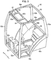
- Fig. 3 is a view for describing an example of the cabin framework 50 in accordance with the present embodiment.
- the cabin framework 50 includes (i) a lateral pair of supporting columns 52a and 52b which are provided at a front part of the cabin framework 50 and (ii) a lateral pair of supporting columns 53a and 53b which are provided at a rear part of the cabin framework 50.
- the cabin framework 50 further includes (i) a beam 54 which connects together respective top parts of the lateral pair of supporting columns 52a and 52b and (ii) a beam 55 which connects together respective top parts of the lateral pair of supporting columns 53a and 53b.
- the cabin framework 50 further includes (i) a beam 56a which connects together the respective top parts supporting columns 52a and 53a that are located on a left side and (ii) a beam 56b which connects together the respective top parts of the supporting columns 52b and 53b that are located on a right side.
- the cabin framework 50 further includes (i) a beam 58 which connects together respective bottom parts of the lateral pair of supporting columns 53a and 53b and (ii) a pair of beams 59a and 59b.
- the beam 59a connects together respective bottom parts of the supporting columns 52a and 53a on the left side.
- the beam 59b connects together respective bottom parts of the supporting columns 52b and 53b on the right side.
- the cabin framework 50 thus defines, by the plurality of beams assembled in a form of a box-like frame, the cabin 12 which is to contain the operation device.
- Rear parts of the beams 59a and 59b are each formed in a shape of a circular arc so as to correspond to respective rear wheel fenders (not illustrated) of the tractor.
- a lateral pair of side panels 60a and 60b are attached at respective lower parts of the beams 59a and 59b.
- a floor sheet is attached to a bottom surface of the cabin framework 50.
- a front panel, door panels, a rear panel, and the roof 20 are respectively attached to a front surface, side surfaces, a back surface, and a ceiling of the cabin framework 50 (none of these is illustrated in Fig. 3 ).
- a skylight frame 62 is provided.
- the skylight frame 62 has a top surface which is formed flat.
- the skylight frame 62 includes a front-side frame 62a and a rear-side frame 62b.
- the front-side frame 62a is welded to the beam 54.
- the rear-side frame 62b is welded to a skylight attachment beam 61 which is provided so as to bridge between the beams 56a and 56b.
- the front-side frame 62a can be attached to the beam 54 by another method in which, for example, bolts and nuts are used.
- the rear-side frame 62b can be attached to the skylight attachment beam 61 by another method in which, for example, bolts and nuts are used.
- Fig. 3 merely shows an example of the cabin framework 50 in accordance with the present embodiment.
- the cabin framework 50 can be achieved by a structure which is different from that illustrated in Fig. 3 .
- Fig. 1 is a view for describing an example of the cabin-protection structure 30 in accordance with the present embodiment.
- Examples of the function fulfilled by the cabin-protection structure 30 encompass (i) protection of an operator from a falling object and (ii) protection of an operator in a case where a construction machine tips over and/or falls.
- the cabin-protection structure 30 is made of, for example, steel.
- the cabin-protection structure 30 can be made of any material and can have, for example, any shape, thickness, and size.
- the cabin-protection structure 30 is provided above the roof 20 with the plurality of support members 40 which are provided between the cabin-protection structure 30 and the roof 20. Therefore, in a case where a falling object strikes the tractor 1 including the cabin-protection structure 30, the cabin-protection structure 30 can protect not only an operator of the tractor 1 but also the roof 20. Specifically, the cabin-protection structure 30, of course, protects the operator of the tractor 1. Then, in addition, the cabin-protection structure 30 can considerably reduce damages to the roof 20 or completely protect the roof 20.
- the cabin-protection structure 30 When viewed from above, the cabin-protection structure 30 has a substantially trapezoidal shape.
- the cabin-protection structure 30 is supported by four support members 40a through 40d at respective four corners of the cabin-protection structure 30.
- the number of the plurality of support members can be any number that is 2 or more.
- the cabin-protection structure 30 can be provided above the roof 20 with one support member provided between the cabin-protection structure 30 and the roof 20. In such a case, the one support member is assumed to have strength which is sufficient to allow the cabin-protection structure 30 to fulfill the functions such as protection of an operator from a falling object.
- An interval between a front-side pair of support members 40a and 40b among the four support members 40a through 40d is preferably identical to or narrower than an interval between a rear-side pair of support members 40c and 40d.
- the support members 40a and 40b are located on a side where an operator sits.
- the cabin-protection structure 30 can more certainly protect the operator and/or the roof 20 from a falling object.
- the following effects can also be obtained.
- a surface of the cabin-protection structure 30, which surface is located on a side where the support member 40a and the support member 40c are located will be referred to as "side surface A”
- a surface of the cabin-protection structure 30, which surface is located on a side where the support member 40b and the support member 40d are located will be referred to as "side surface B”.
- the side surface A and the side surface B are each angled with respect to a direction in which the tractor 1 is advancing.
- an impact of the falling object on the cabin-protection structure 30 (or the tractor 1) can be distributed in directions which are oblique with respect to the direction in which the tractor 1 is advancing. This allows the tractor 1 to adequately protect an operator. In addition, since an impact on the tractor 1 is also reduced, damages to the tractor 1 itself can be reduced. Thus, in a case where the interval between the front-side pair of support members 40a and 40b is narrower than the interval between the rear-side pair of support members 40c and 40d, various effects can be expected. These effects are directly related to safety of an operator and of the tractor 1. These reasons reveal that the tractor 1 can have improved usability.
- the cabin-protection structure 30 is preferably open at a portion directly above the skylight of the roof 20. This allows the cabin-protection structure 30 to simultaneously (i) protect an operator from a falling object and (ii) secure visibility of the operator through the skylight.
- the support members 40a and 40b are preferably fixed to the skylight frame 62. In this way, designing, processing, or the like of the roof 20 to fix the support members 40a and 40b can be unnecessary (examples of the processing encompass making holes through which bolts or screws are to be inserted). This allows a process of producing and assembling the tractor 1 to be simpler.
- the support members 40a through 40d are preferably configured so as to maintain a distance between the cabin-protection structure 30 and the roof 20 so that the distance falls within a certain range.
- the distance between the cabin-protection structure 30 and the roof 20 is preferably adjusted by a length of each of the support members 40a through 40d.
- a proper distance between the cabin-protection structure 30 and the roof 20 varies, depending on the shape, the material, thickness, and the like of the cabin-protection structure 30. Therefore, the lengths of the support members 40a through 40d are decided in view of the material and the like of the cabin-protection structure 30. This makes it possible to maintain the distance between the cabin-protection structure 30 and the roof 20 within the certain range, and therefore deals with the reasons A) and B).
- the certain range can be decided by the following methods. For example, the shape, the material, the thickness, and the like of the cabin-protection structure 30 are variously changed, and then experiments, in each of which a falling object strikes the cabin-protection structure 30, are carried out. Then, the certain range is decided according to the results of each of the experiments. Alternatively, the certain range is decided according to the results of experiments in which falling of a falling object on the cabin-protection structure 30 is simulated.
- the support members 40a through 40d will be further described below.
- a cabin framework and a cabin-protection structure are welded to each other. According to the conventional tractors, there was thus no technical idea of supporting the cabin-protection structure 30 with use of the support members 40a through 40d. The following description will discuss ingenuity in where to attach the support members 40a through 40d and effects of the ingenuity, which are irrelevant to the conventional tractors.
- the roof 20 is joined to the cabin framework 50 at a plurality of joining positions with use of, for example, (i) bolts and nuts or (ii) screws.
- the cabin-protection structure 30 is preferably provided above the roof 20 with the support members 40a through 40d which are provided between the cabin-protection structure 30 and the roof 20. At least some support members among the plurality of support members are attached to respective joining positions among the plurality of joining positions where the roof is jointed to the cabin framework.
- the support members 40a through 40d will be described in detail below. It is possible to provide that all of the respective support members be provided at the respective plurality of joining positions where the roof is jointed to the cabin framework.
- the number of support members is preferably at least the same as the number of joining positions, with at least some of the support members being provided at respective joining positions among the plurality of joining positions.
- the roof 20 and the cabin-protection structure 30 are joined together at four joining positions.
- the roof 20 and the cabin framework 50 are joined together at four joining positions.
- a total number of joining positions is 8.
- a total number of joining positions is 4.
- various effects can be expected.
- the joining positions of the roof 20 and the cabin framework 50 and the joining positions of the roof 20 and the cabin-protection structure 30 can be made identical by, for example, the following method.
- the roof 20 and the cabin framework 50 are joined together with use of four bolts.
- positions of the holes 30a through 30d correspond to positions of the holes 21a through 21d, respectively.
- support member a bolt and a nut and/or a collar are collectively referred to as "support member”.
- the steps (1) through (4) are so easy that a user of the tractor 1 can carry out the steps (1) through (4).
- the user of the tractor 1 can remove and attach the cabin-protection structure 30 without others' help. Therefore, in a case where, for example, the cabin-protection structure 30 breaks, it is sufficient to purchase a new cabin-protection structure 30 without the need for replacing the tractor 1.
- the cabin-protection structure 30 in accordance with the present embodiment can be thus designed, produced, processed, repaired, or replaced, independently of the tractor 1.
- the tractor 1 has improved usability in this regard also.
- the cabin 12 which includes the cabin-protection structure 30 and the roof 20, can be designed, produced, processed, repaired, or replaced, independently of the tractor 1.
- the tractor 1 including such a cabin 12 can also bring about the various effects described above.
- Such a tractor 1 can be used for, for example, agriculture, forestry, and civil engineering works.
- the present invention is not limited to the embodiments, but can be altered by a skilled person in the art within the scope of the claims.
- the present invention also encompasses, in its technical scope, any embodiment derived by combining technical means disclosed in differing embodiments.
Landscapes
- Engineering & Computer Science (AREA)
- Mechanical Engineering (AREA)
- Chemical & Material Sciences (AREA)
- Combustion & Propulsion (AREA)
- Transportation (AREA)
- Body Structure For Vehicles (AREA)
Abstract
Description
- The present invention relates to a cabin-protection structure and to a tractor.
- In general, a construction machine includes a cabin-protection structure. Examples of the function fulfilled by the cabin-protection structure encompass (i) protection of an operator from a falling object and (ii) protection of an operator in a case where the construction machine tips over and/or falls.
- Patent Literature 1 discloses a conventional tractor (see
Figs. 1 and 2 of Patent Literature 1). The tractor disclosed in Patent Literature 1 includes (i) an internal frame 10, (ii) a plurality of members 24 and 26a through 26d, (iii) and a roof panel 43. The plurality of members 24 and 26a through 26d are provided at a top part of the internal frame 10. The members 26a through 26d protect an operator from a falling object (see paragraph [0081]). The roof panel 43 is provided above the plurality of members 24 and 26a through 26d. - According to the conventional tractor, the internal frame 10, the plurality of members 24 and 26a through 26d, and the roof panel 43 are thus provided in this order.
- [Patent Literature 1]
Specification ofU.S. Patent Application Publication No. 2016/0114838 (Publication Date: April 28, 2016 ) - However, the tractor disclosed in Patent Literature 1 poses, for example, the following problems (1) through (3):
- (1) The plurality of members, which are included in the internal frame, are welded together so as to be rigidly secured together (see paragraphs [0070], [0081], and the like). It is therefore difficult to remove the plurality of members from the internal frame 10 after the welding of the plurality of members is finished.
- (2) The roof panel 43 is provided above the plurality of members 24 and 26a through 26d. Therefore, in a case where a falling object strikes the tractor, the roof panel 43 is damaged first. Depending on a material for the roof panel 43, it may be necessary to frequently replace the roof panel 43. That is, a conventional roof panel is not sufficiently recognized as an object to be protected from a falling object.
- (3) Because of the problem (1) above, it is difficult to adjust a height of an entire portion of the tractor disclosed in Patent Literature 1. Therefore, the tractor of Patent Literature 1 can only be accommodated in a space having a certain height.
- As evidenced by the various problems above, the conventional tractor has room for improvement in terms of usability.
- The present invention has been made in view of the problems, and an object of the present invention is to achieve a cabin-protection structure and a tractor, each of which has improved usability.
- In order to attain the object, a cabin-protection structure in accordance with an embodiment of the present invention is a cabin-protection structure for a tractor, the tractor including: a cabin framework that defines a cabin containing an operation device; and a roof provided above the cabin framework, the cabin-protection structure being provided above the roof.
- With the configuration, the roof is provided between the cabin-protection structure and the cabin framework. This allows the tractor to be structured so that it is unnecessary to weld the cabin framework and the cabin-protection structure to each other. It is therefore possible to solve a conventional problem of difficulty in removing a cabin framework from a cabin-protection structure.
- In addition, the cabin-protection structure is provided above the roof. With this configuration, it is possible for the cabin-protection structure to protect not only an operator of the tractor but also the roof in a case where a falling object strikes the tractor which includes the cabin-protection structure.
- Furthermore, in a case where the cabin-protection structure is configured to be detachable from the roof, it is easy to adjust a height of the tractor. For example, in a case where a space to accommodate the tractor is low in height, it is sufficient to remove the cabin-protection structure from the roof.
- With the configuration, the cabin-protection structure can have usability which is thus improved.
- In order to attain the object, a tractor in accordance with an embodiment of the present invention is a tractor including: a cabin framework that defines a cabin containing an operation device; a roof provided above the cabin framework; and a cabin-protection structure provided above the roof.
- With the configuration, it is possible to bring about an advantageous effect similar to the advantageous effect of the cabin-protection structure.
- With an aspect of the present invention, it is possible to provide a cabin-protection structure and a tractor, each of which has improved usability.
-
-
Fig. 1 is a view for describing an example of a cabin-protection structure in accordance with the present embodiment. -
Fig. 2 is a view illustrating an overall configuration of a tractor in accordance with the present embodiment. -
Fig. 3 is a view for describing an example of a cabin framework in accordance with the present embodiment. - In the following description, an arrow U, an arrow D, an arrow F, an arrow B, an arrow L, and an arrow R in
Figs. 2 and3 refer to an upward direction, a downward direction, a frontward direction, a backward direction, a leftward direction, and a rightward direction, respectively. - An overall configuration of a tractor 1 will be described first with reference to
Fig. 2. Fig. 2 is a view illustrating the overall configuration of the tractor 1. - The tractor 1 includes a
body frame 2,front wheels 3,rear wheels 4, anengine 5, ahood 6, atransmission 7, a steering wheel 8, aseat 11, acabin 12, acabin framework 50, aroof 20, a cabin-protection structure 30, andsupport members 40. - The
body frame 2 is provided so that a longer side of thebody frame 2 extends in the frontward direction and the backward direction. A front part of thebody frame 2 is supported by the lateral pair offront wheels 3 with a front axle mechanism (not illustrated) provided between the front part of thebody frame 2 and the lateral pair offront wheels 3. Thetransmission 7 is provided at a rear part of thebody frame 2. A rear part of thetransmission 7 is supported by the lateral pair ofrear wheels 4 with a rear axle mechanism (not illustrated) provided between the rear part of thetransmission 7 and the lateral pair ofrear wheels 4. Theengine 5 is provided at the front part of thebody frame 2. Theengine 5 is covered with thehood 6. - Motive power of the
engine 5 is changed in speed by thetransmission 7, and then (i) transmitted to thefront wheels 3 via the front axle mechanism and (ii) transmitted to therear wheels 4 via the rear axle mechanism. The motive power of theengine 5 drives thefront wheels 3 and therear wheels 4 to each rotate. This allows the tractor 1 to run. - The
cabin 12 is provided behind theengine 5. In thecabin 12, there is provided aspace 12a in which an operator is to ride. In thespace 12a, the following, for example, are contained: (i) an operation device (e.g., the steering wheel 8 for controlling an angle in which thefront wheels 3 are to be steered, and various operation tools); and (ii) theseat 11 on which the operator is to sit. - The
roof 20 is provided above thecabin framework 50. Specifically, theroof 20 is attached to thecabin framework 50 with use of, for example, (i) bolts and nuts or (ii) screws. - The cabin-
protection structure 30 is provided above theroof 20 with the plurality ofsupport members 40 which are provided between the cabin-protection structure 30 and theroof 20. - The
cabin framework 50 will be described below with reference toFig. 3. Fig. 3 is a view for describing an example of thecabin framework 50 in accordance with the present embodiment. - The
cabin framework 50 includes (i) a lateral pair of supportingcolumns cabin framework 50 and (ii) a lateral pair of supportingcolumns cabin framework 50. Thecabin framework 50 further includes (i) abeam 54 which connects together respective top parts of the lateral pair of supportingcolumns beam 55 which connects together respective top parts of the lateral pair of supportingcolumns cabin framework 50 further includes (i) abeam 56a which connects together the respective topparts supporting columns beam 56b which connects together the respective top parts of the supportingcolumns cabin framework 50 further includes (i) abeam 58 which connects together respective bottom parts of the lateral pair of supportingcolumns beams beam 59a connects together respective bottom parts of the supportingcolumns beam 59b connects together respective bottom parts of the supportingcolumns cabin framework 50 thus defines, by the plurality of beams assembled in a form of a box-like frame, thecabin 12 which is to contain the operation device. - Rear parts of the
beams side panels beams cabin framework 50, a floor sheet is attached. A front panel, door panels, a rear panel, and theroof 20 are respectively attached to a front surface, side surfaces, a back surface, and a ceiling of the cabin framework 50 (none of these is illustrated inFig. 3 ). - At a front side of a top part of the
cabin framework 50, askylight frame 62 is provided. Theskylight frame 62 has a top surface which is formed flat. Theskylight frame 62 includes a front-side frame 62a and a rear-side frame 62b. The front-side frame 62a is welded to thebeam 54. The rear-side frame 62b is welded to askylight attachment beam 61 which is provided so as to bridge between thebeams side frame 62a can be attached to thebeam 54 by another method in which, for example, bolts and nuts are used. Note also that the rear-side frame 62b can be attached to theskylight attachment beam 61 by another method in which, for example, bolts and nuts are used. -
Fig. 3 merely shows an example of thecabin framework 50 in accordance with the present embodiment. Alternatively, thecabin framework 50 can be achieved by a structure which is different from that illustrated inFig. 3 . - The cabin-
protection structure 30 will be described below with reference toFig. 1. Fig. 1 is a view for describing an example of the cabin-protection structure 30 in accordance with the present embodiment. - Examples of the function fulfilled by the cabin-
protection structure 30 encompass (i) protection of an operator from a falling object and (ii) protection of an operator in a case where a construction machine tips over and/or falls. The cabin-protection structure 30 is made of, for example, steel. However, provided that the function is fulfilled, the cabin-protection structure 30 can be made of any material and can have, for example, any shape, thickness, and size. - The cabin-
protection structure 30 is provided above theroof 20 with the plurality ofsupport members 40 which are provided between the cabin-protection structure 30 and theroof 20. Therefore, in a case where a falling object strikes the tractor 1 including the cabin-protection structure 30, the cabin-protection structure 30 can protect not only an operator of the tractor 1 but also theroof 20. Specifically, the cabin-protection structure 30, of course, protects the operator of the tractor 1. Then, in addition, the cabin-protection structure 30 can considerably reduce damages to theroof 20 or completely protect theroof 20. - When viewed from above, the cabin-
protection structure 30 has a substantially trapezoidal shape. The cabin-protection structure 30 is supported by foursupport members 40a through 40d at respective four corners of the cabin-protection structure 30. - The number of the plurality of support members can be any number that is 2 or more. The cabin-
protection structure 30 can be provided above theroof 20 with one support member provided between the cabin-protection structure 30 and theroof 20. In such a case, the one support member is assumed to have strength which is sufficient to allow the cabin-protection structure 30 to fulfill the functions such as protection of an operator from a falling object. - An interval between a front-side pair of
support members support members 40a through 40d is preferably identical to or narrower than an interval between a rear-side pair ofsupport members support members support members protection structure 30 can more certainly protect the operator and/or theroof 20 from a falling object. - In a case where the interval between the front-side pair of
support members support members protection structure 30, which surface is located on a side where thesupport member 40a and thesupport member 40c are located, will be referred to as "side surface A", and a surface of the cabin-protection structure 30, which surface is located on a side where thesupport member 40b and thesupport member 40d are located, will be referred to as "side surface B". In this case, the side surface A and the side surface B are each angled with respect to a direction in which the tractor 1 is advancing. Therefore, in a case where a falling object strikes the side surface A and/or the side surface B, an impact of the falling object on the cabin-protection structure 30 (or the tractor 1) can be distributed in directions which are oblique with respect to the direction in which the tractor 1 is advancing. This allows the tractor 1 to adequately protect an operator. In addition, since an impact on the tractor 1 is also reduced, damages to the tractor 1 itself can be reduced. Thus, in a case where the interval between the front-side pair ofsupport members support members - The description of the cabin-
protection structure 30 will be continued below. - The cabin-
protection structure 30 is preferably open at a portion directly above the skylight of theroof 20. This allows the cabin-protection structure 30 to simultaneously (i) protect an operator from a falling object and (ii) secure visibility of the operator through the skylight. - The
support members skylight frame 62. In this way, designing, processing, or the like of theroof 20 to fix thesupport members - Because of the reasons A) and B) below, the
support members 40a through 40d are preferably configured so as to maintain a distance between the cabin-protection structure 30 and theroof 20 so that the distance falls within a certain range. - A) In a case where the distance between the cabin-
protection structure 30 and theroof 20 is above the certain range, there may be an increase in a load to be applied to thesupport members 40a through 40d when a falling object strikes the cabin-protection structure 30. This requires additional caution when strength of thesupport members 40a through 40d is designed. - B) In a case where the distance between the cabin-
protection structure 30 and theroof 20 is smaller than the certain distance, there is a possibility that an impact of a falling object causes the cabin-protection structure 30 to come into contact with theroof 20, so that theroof 20 becomes damaged. - For these reasons, the distance between the cabin-
protection structure 30 and theroof 20 is preferably adjusted by a length of each of thesupport members 40a through 40d. A proper distance between the cabin-protection structure 30 and theroof 20 varies, depending on the shape, the material, thickness, and the like of the cabin-protection structure 30. Therefore, the lengths of thesupport members 40a through 40d are decided in view of the material and the like of the cabin-protection structure 30. This makes it possible to maintain the distance between the cabin-protection structure 30 and theroof 20 within the certain range, and therefore deals with the reasons A) and B). - Note that the certain range can be decided by the following methods. For example, the shape, the material, the thickness, and the like of the cabin-
protection structure 30 are variously changed, and then experiments, in each of which a falling object strikes the cabin-protection structure 30, are carried out. Then, the certain range is decided according to the results of each of the experiments. Alternatively, the certain range is decided according to the results of experiments in which falling of a falling object on the cabin-protection structure 30 is simulated. - The
support members 40a through 40d will be further described below. - According to conventional tractors, a cabin framework and a cabin-protection structure are welded to each other. According to the conventional tractors, there was thus no technical idea of supporting the cabin-
protection structure 30 with use of thesupport members 40a through 40d. The following description will discuss ingenuity in where to attach thesupport members 40a through 40d and effects of the ingenuity, which are irrelevant to the conventional tractors. - The
roof 20 is joined to thecabin framework 50 at a plurality of joining positions with use of, for example, (i) bolts and nuts or (ii) screws. The cabin-protection structure 30 is preferably provided above theroof 20 with thesupport members 40a through 40d which are provided between the cabin-protection structure 30 and theroof 20. At least some support members among the plurality of support members are attached to respective joining positions among the plurality of joining positions where the roof is jointed to the cabin framework. Thesupport members 40a through 40d will be described in detail below. It is possible to provide that all of the respective support members be provided at the respective plurality of joining positions where the roof is jointed to the cabin framework. It is also possible that some of the support members be provided at the corresponding joining positions, and the remaining support members be provided at positions close to other joining positions. The number of support members is preferably at least the same as the number of joining positions, with at least some of the support members being provided at respective joining positions among the plurality of joining positions. - According to the tractor 1, the
roof 20 and the cabin-protection structure 30 are joined together at four joining positions. In addition, it is assumed that theroof 20 and thecabin framework 50 are joined together at four joining positions. In a case where the joining positions of theroof 20 and thecabin framework 50 are different from the joining positions of theroof 20 and the cabin-protection structure 30, a total number of joining positions is 8. Meanwhile, in a case where the joining positions of theroof 20 and thecabin framework 50 are identical to the joining positions of theroof 20 and the cabin-protection structure 30, a total number of joining positions is 4. In a case where the total number of joining positions is small, various effects can be expected. For example, it is possible to reduce a total number of holes which are to be made in theroof 20 and through which bolts or screws are to be inserted. This makes it easy to design, produce, and process theroof 20. In addition, since the number of bolts or screws necessary are dependent on the number of holes, a smaller number of holes allows for a greater reduction in the number of bolts or screws. - The joining positions of the
roof 20 and thecabin framework 50 and the joining positions of theroof 20 and the cabin-protection structure 30 can be made identical by, for example, the following method. - It is assumed that the
roof 20 and thecabin framework 50 are joined together with use of four bolts. In this case, there are four holes 21a through 21d made in theroof 20 so that the four bolts are to be inserted through the four holes 21a through 21d, respectively. It is also assumed that there are four holes 30a through 30d made in the cabin-protection structure 30. It is also assumed that positions of the holes 30a through 30d correspond to positions of the holes 21a through 21d, respectively. - In this case, (1) the four bolts, which join the
roof 20 and thecabin framework 50 together, are removed and (2) the four holes 21a through 21d of theroof 20 are opened. Then, (3) four bolts for fixing the cabin-protection structure 30, theroof 20, and thecabin framework 50 together are inserted through the holes 21a through 21d and into the holes 30a through 30d and then (4) the four bolts are finally tightened with corresponding nuts. This allows the joining positions of theroof 20 and thecabin framework 50 and the joining positions of theroof 20 and the cabin-protection structure 30 to be identical. - Note that it is possible to increase the strength of the
support members 40a through 40d by using collars when the bolts are inserted in the step (3) above. In the present embodiment, a bolt and a nut and/or a collar are collectively referred to as "support member". - With the method including the steps (1) through (4) above, it is possible to cause the cabin-
protection structure 30 to be detachable from theroof 20. This allows a height of an entire portion of the tractor 1 to be adjusted, and, as a result, allows the tractor 1 to be accommodated in more places. - The steps (1) through (4) are so easy that a user of the tractor 1 can carry out the steps (1) through (4). Specifically, the user of the tractor 1 can remove and attach the cabin-
protection structure 30 without others' help. Therefore, in a case where, for example, the cabin-protection structure 30 breaks, it is sufficient to purchase a new cabin-protection structure 30 without the need for replacing the tractor 1. Alternatively, it is possible to attach a cabin-protection structure 30 to another tractor owned by the user. The cabin-protection structure 30 in accordance with the present embodiment can be thus designed, produced, processed, repaired, or replaced, independently of the tractor 1. The tractor 1 has improved usability in this regard also. - Likewise, the
cabin 12, which includes the cabin-protection structure 30 and theroof 20, can be designed, produced, processed, repaired, or replaced, independently of the tractor 1. The tractor 1 including such acabin 12 can also bring about the various effects described above. - Such a tractor 1 can be used for, for example, agriculture, forestry, and civil engineering works.
- The present invention is not limited to the embodiments, but can be altered by a skilled person in the art within the scope of the claims. The present invention also encompasses, in its technical scope, any embodiment derived by combining technical means disclosed in differing embodiments.
-
- 1 Tractor
- 2 Body frame
- 3, 3 Front wheel
- 4, 4 Rear wheel
- 5 Engine
- 6 Hood
- 7 Transmission
- 8 Steering wheel
- 11 Seat
- 12 Cabin
- 12a Space
- 20 Roof
- 30 Cabin-protection structure
- 40 and 40a through 40d Support member
- 50 Cabin framework
- 52a, 52a and 52b, 52a and 53a, 52b, 53a and 53b
- Supporting column
- 54, 55, 56a, 56a and 56b, 56b, 58, 59a and 59b Beam
- 60a, 60b Side panel
- 61 Skylight attachment beam
- 62 Skylight frame
- 62a Front-side frame
- 62b Rear-side frame
Claims (9)
- A cabin-protection structure for a tractor,
the tractor including:a cabin framework (50) that defines a cabin (12) containing an operation device (8); anda roof (20) provided above the cabin framework,the cabin-protection structure (30) being configured to be provided above the roof. - A tractor, comprising:a cabin framework (50) that defines a cabin (12) containing an operation device (8);a roof (20) provided above the cabin framework; anda cabin-protection structure (30) provided above the roof.
- The tractor according to claim 2, wherein
the cabin-protection structure (30) is detachable from the roof. - The tractor according to claim 2 or 3, wherein:the roof (20) has a skylight (62); andthe cabin-protection structure (30) is open at a portion directly above the skylight.
- The tractor according to any one of claims 2 to 4, wherein:the roof (20) is fixed to the cabin framework (50) at a plurality of positions; andthe cabin-protection structure (30) is provided above the roof (20) with a plurality of support members (40) which are provided between the cabin-protection structure and the roof.
- The tractor according to claim 5, wherein at least some support members among the plurality of support members (40) are provided at respective positions among the plurality of positions.
- The tractor according to claim 5 or 6, wherein
the plurality of support members (40) include a front pair of support members (40a, 40b) and a rear pair of support members (40c, 40d) so as to support the cabin-protection structure (30); and
an interval between the front pair of support members is narrower than an interval between the rear pair of support members. - The tractor according to claim 7 in combination with claim 4, wherein:the front pair of support members (40a, 40b) are fixed to a skylight frame (62) that defines the skylight.
- The tractor according to any one of claims 5 to 8, wherein
the plurality of support members (40) maintain a distance between the cabin-protection structure (30) and the roof (20) so that the distance falls within a certain range.
Priority Applications (4)
| Application Number | Priority Date | Filing Date | Title |
|---|---|---|---|
| EP18305062.4A EP3517413B1 (en) | 2018-01-25 | 2018-01-25 | Cabin-protection structure and tractor |
| JP2019009165A JP7008646B2 (en) | 2018-01-25 | 2019-01-23 | Tractor |
| US16/255,887 US10857962B2 (en) | 2018-01-25 | 2019-01-24 | Cabin-protection structure and tractor |
| CN201910073832.9A CN110077475B (en) | 2018-01-25 | 2019-01-25 | Cab protection structure and tractor |
Applications Claiming Priority (1)
| Application Number | Priority Date | Filing Date | Title |
|---|---|---|---|
| EP18305062.4A EP3517413B1 (en) | 2018-01-25 | 2018-01-25 | Cabin-protection structure and tractor |
Publications (2)
| Publication Number | Publication Date |
|---|---|
| EP3517413A1 true EP3517413A1 (en) | 2019-07-31 |
| EP3517413B1 EP3517413B1 (en) | 2020-07-08 |
Family
ID=61163624
Family Applications (1)
| Application Number | Title | Priority Date | Filing Date |
|---|---|---|---|
| EP18305062.4A Active EP3517413B1 (en) | 2018-01-25 | 2018-01-25 | Cabin-protection structure and tractor |
Country Status (4)
| Country | Link |
|---|---|
| US (1) | US10857962B2 (en) |
| EP (1) | EP3517413B1 (en) |
| JP (1) | JP7008646B2 (en) |
| CN (1) | CN110077475B (en) |
Families Citing this family (9)
| Publication number | Priority date | Publication date | Assignee | Title |
|---|---|---|---|---|
| EP3517413B1 (en) * | 2018-01-25 | 2020-07-08 | Kubota Corporation | Cabin-protection structure and tractor |
| CN110696935A (en) * | 2019-11-18 | 2020-01-17 | 徐工集团工程机械股份有限公司 | Cab and engineering vehicle |
| US11285899B2 (en) * | 2020-04-23 | 2022-03-29 | Caterpillar Inc. | Guard assembly |
| WO2023200871A1 (en) * | 2022-04-12 | 2023-10-19 | Manitou Equipment America, Llc | Utility vehicle operator cab roof |
| DE102023107102A1 (en) * | 2023-03-21 | 2024-09-26 | Echle Hartstahl Gmbh | Protective roof for a work vehicle cabin |
| US12257969B2 (en) * | 2023-06-01 | 2025-03-25 | Kawasaki Motors, Ltd. | Off-road vehicle, reinforcing frame, and method for transporting off-road vehicle |
| CN116650875A (en) * | 2023-07-07 | 2023-08-29 | 山东信力工矿安全检测有限公司 | A coal mine underground trackless fire truck |
| IT202300021153A1 (en) * | 2023-10-11 | 2025-04-11 | Cnh Ind Italia Spa | IMPROVED ROOF SAFETY GROUP FOR A WORK VEHICLE |
| DE102024126247A1 (en) * | 2024-09-12 | 2026-03-12 | Rheinmetall MAN Military Vehicles Österreich GesmbH | CAB AND COMMERCIAL VEHICLE |
Citations (6)
| Publication number | Priority date | Publication date | Assignee | Title |
|---|---|---|---|---|
| JPH0557047U (en) * | 1991-12-27 | 1993-07-30 | 株式会社小松製作所 | Power shovel cab skylight guard |
| JP2003146164A (en) * | 2001-11-15 | 2003-05-21 | Kubota Corp | Farm tractor |
| EP1728689A1 (en) * | 2005-06-01 | 2006-12-06 | Volvo Construction Equipment Holding Sweden AB | Operator protective structure installed on cabin of construction machine |
| JP2013173497A (en) * | 2012-02-27 | 2013-09-05 | Iseki & Co Ltd | Working vehicle |
| US20140292032A1 (en) * | 2013-03-29 | 2014-10-02 | Komatsu Ltd. | Operator protective guard, guard-equipped cab for work machine, and work machine |
| US20160114838A1 (en) | 2013-06-04 | 2016-04-28 | Cnh Industrial America Llc | Vehicle cab assembly |
Family Cites Families (22)
| Publication number | Priority date | Publication date | Assignee | Title |
|---|---|---|---|---|
| US4095839A (en) * | 1976-05-24 | 1978-06-20 | Caterpillar Tractor Co. | Falling object protective structure |
| US4184712A (en) * | 1978-05-16 | 1980-01-22 | J. I. Case Company | Enclosure mechanism for roll over protective structure |
| JPH01107622U (en) * | 1988-01-14 | 1989-07-20 | ||
| JP2562274Y2 (en) * | 1991-08-01 | 1998-02-10 | 株式会社神戸製鋼所 | Cabin vibration control device for construction machinery |
| JP3059538B2 (en) | 1991-09-02 | 2000-07-04 | サミー株式会社 | Gaming machine |
| DE4218069A1 (en) * | 1992-06-01 | 1993-12-02 | Helmut Hagedorn | Stump grubber for garden tractor - has wheeled or continuously tracked tractor to which it is pivotably connected by lift and is movable between transport and work positions |
| JP3747733B2 (en) * | 2000-03-28 | 2006-02-22 | 日立建機株式会社 | Construction machine cab |
| KR100464734B1 (en) * | 2001-12-18 | 2005-01-05 | 볼보 컨스트럭션 이키프먼트 홀딩 스웨덴 에이비 | An apparatus equiped in driving room that supports driver's protector |
| JP2005145182A (en) * | 2003-11-13 | 2005-06-09 | Hitachi Constr Mach Co Ltd | Construction machinery |
| GB2441484B8 (en) * | 2005-07-19 | 2010-07-28 | Komatsu Mfg Co Ltd | Cab structure for construction machine. |
| JP2007069822A (en) | 2005-09-08 | 2007-03-22 | Shin Caterpillar Mitsubishi Ltd | Cab and working machine |
| US20070205633A1 (en) * | 2006-03-01 | 2007-09-06 | Waco Douglas L | Roof system with integrated hvac ducting |
| JP5208290B1 (en) * | 2012-02-23 | 2013-06-12 | 株式会社小松製作所 | Work vehicle cab and work vehicle |
| US8998253B2 (en) * | 2012-03-30 | 2015-04-07 | Polaris Industries Inc. | Folding cab frame |
| WO2013191308A1 (en) * | 2012-06-18 | 2013-12-27 | 볼보 컨스트럭션 이큅먼트 에이비 | Cab protection apparatus for construction machinery |
| JP2015112880A (en) | 2013-12-06 | 2015-06-22 | ヤンマー株式会社 | Roof structure of cabin |
| US9346495B2 (en) * | 2014-04-21 | 2016-05-24 | Caterpillar Inc. | Machine cabin having improved operator visibility |
| CN204266281U (en) * | 2014-12-01 | 2015-04-15 | 中联重科股份有限公司渭南分公司 | construction machinery |
| IN2015DN01656A (en) * | 2014-12-11 | 2015-08-14 | Komatsu Mfg Co Ltd | |
| KR101717059B1 (en) | 2015-07-01 | 2017-03-16 | 가부시키가이샤 고마쓰 세이사쿠쇼 | Cab for work vehicle and a method of manufacturing same |
| EP3517413B1 (en) * | 2018-01-25 | 2020-07-08 | Kubota Corporation | Cabin-protection structure and tractor |
| DE102018206111A1 (en) * | 2018-04-20 | 2019-10-24 | Deere & Company | roof structure |
-
2018
- 2018-01-25 EP EP18305062.4A patent/EP3517413B1/en active Active
-
2019
- 2019-01-23 JP JP2019009165A patent/JP7008646B2/en active Active
- 2019-01-24 US US16/255,887 patent/US10857962B2/en active Active
- 2019-01-25 CN CN201910073832.9A patent/CN110077475B/en active Active
Patent Citations (6)
| Publication number | Priority date | Publication date | Assignee | Title |
|---|---|---|---|---|
| JPH0557047U (en) * | 1991-12-27 | 1993-07-30 | 株式会社小松製作所 | Power shovel cab skylight guard |
| JP2003146164A (en) * | 2001-11-15 | 2003-05-21 | Kubota Corp | Farm tractor |
| EP1728689A1 (en) * | 2005-06-01 | 2006-12-06 | Volvo Construction Equipment Holding Sweden AB | Operator protective structure installed on cabin of construction machine |
| JP2013173497A (en) * | 2012-02-27 | 2013-09-05 | Iseki & Co Ltd | Working vehicle |
| US20140292032A1 (en) * | 2013-03-29 | 2014-10-02 | Komatsu Ltd. | Operator protective guard, guard-equipped cab for work machine, and work machine |
| US20160114838A1 (en) | 2013-06-04 | 2016-04-28 | Cnh Industrial America Llc | Vehicle cab assembly |
Also Published As
| Publication number | Publication date |
|---|---|
| US10857962B2 (en) | 2020-12-08 |
| JP7008646B2 (en) | 2022-01-25 |
| JP2019127264A (en) | 2019-08-01 |
| CN110077475B (en) | 2022-11-22 |
| CN110077475A (en) | 2019-08-02 |
| EP3517413B1 (en) | 2020-07-08 |
| US20190225176A1 (en) | 2019-07-25 |
Similar Documents
| Publication | Publication Date | Title |
|---|---|---|
| EP3517413B1 (en) | Cabin-protection structure and tractor | |
| EP2570334B1 (en) | Front part body structure of vehicle | |
| US10967825B2 (en) | Utility vehicle | |
| US20190084457A1 (en) | Skeletal structure | |
| JP2007276703A (en) | Work four-wheeler | |
| EP2923926B1 (en) | Radiator shroud structure | |
| JP6794942B2 (en) | Pillar skeleton structure and body module structure | |
| US9045104B2 (en) | Rough-terrain traveling vehicle | |
| JP5071298B2 (en) | Construction machinery | |
| JP2006056325A (en) | Cab for construction machine | |
| JP2004114952A (en) | Cabin of construction machine | |
| JP2005329799A (en) | Construction machinery | |
| US20140354010A1 (en) | Cab frame for construction machinery and painting method therefor | |
| JP2007063839A (en) | Protection structure for construction equipment, and cab for construction equipment | |
| JP4191585B2 (en) | Construction machinery cab | |
| EP1754835A1 (en) | Canopy installation structure in working vehicle | |
| JP2005075236A (en) | Body frame connection structure | |
| JP4671409B2 (en) | STRUCTURE, STRUCTURAL COMPONENT AND METHOD FOR PRODUCING STRUCTURE | |
| JP2004161114A (en) | Cab for construction machine | |
| JP2017053191A (en) | Front guard structure of construction machine | |
| JP2005035316A (en) | Operator cab reinforcing structure | |
| CN214940591U (en) | Excavator and its main beam frame | |
| JP4291206B2 (en) | Construction machinery cab | |
| JP2001260951A (en) | Component structure | |
| JP6560027B2 (en) | Tractor |
Legal Events
| Date | Code | Title | Description |
|---|---|---|---|
| PUAI | Public reference made under article 153(3) epc to a published international application that has entered the european phase |
Free format text: ORIGINAL CODE: 0009012 |
|
| STAA | Information on the status of an ep patent application or granted ep patent |
Free format text: STATUS: REQUEST FOR EXAMINATION WAS MADE |
|
| 17P | Request for examination filed |
Effective date: 20190517 |
|
| AK | Designated contracting states |
Kind code of ref document: A1 Designated state(s): AL AT BE BG CH CY CZ DE DK EE ES FI FR GB GR HR HU IE IS IT LI LT LU LV MC MK MT NL NO PL PT RO RS SE SI SK SM TR |
|
| AX | Request for extension of the european patent |
Extension state: BA ME |
|
| GRAP | Despatch of communication of intention to grant a patent |
Free format text: ORIGINAL CODE: EPIDOSNIGR1 |
|
| STAA | Information on the status of an ep patent application or granted ep patent |
Free format text: STATUS: GRANT OF PATENT IS INTENDED |
|
| RIC1 | Information provided on ipc code assigned before grant |
Ipc: B62D 33/06 20060101AFI20190822BHEP Ipc: B60R 21/11 20060101ALI20190822BHEP |
|
| INTG | Intention to grant announced |
Effective date: 20190924 |
|
| GRAS | Grant fee paid |
Free format text: ORIGINAL CODE: EPIDOSNIGR3 |
|
| GRAA | (expected) grant |
Free format text: ORIGINAL CODE: 0009210 |
|
| STAA | Information on the status of an ep patent application or granted ep patent |
Free format text: STATUS: THE PATENT HAS BEEN GRANTED |
|
| AK | Designated contracting states |
Kind code of ref document: B1 Designated state(s): AL AT BE BG CH CY CZ DE DK EE ES FI FR GB GR HR HU IE IS IT LI LT LU LV MC MK MT NL NO PL PT RO RS SE SI SK SM TR |
|
| REG | Reference to a national code |
Ref country code: AT Ref legal event code: REF Ref document number: 1288157 Country of ref document: AT Kind code of ref document: T Effective date: 20200715 Ref country code: CH Ref legal event code: EP |
|
| REG | Reference to a national code |
Ref country code: DE Ref legal event code: R096 Ref document number: 602018005909 Country of ref document: DE |
|
| REG | Reference to a national code |
Ref country code: IE Ref legal event code: FG4D |
|
| REG | Reference to a national code |
Ref country code: LT Ref legal event code: MG4D |
|
| REG | Reference to a national code |
Ref country code: AT Ref legal event code: MK05 Ref document number: 1288157 Country of ref document: AT Kind code of ref document: T Effective date: 20200708 |
|
| REG | Reference to a national code |
Ref country code: NL Ref legal event code: MP Effective date: 20200708 |
|
| PG25 | Lapsed in a contracting state [announced via postgrant information from national office to epo] |
Ref country code: FI Free format text: LAPSE BECAUSE OF FAILURE TO SUBMIT A TRANSLATION OF THE DESCRIPTION OR TO PAY THE FEE WITHIN THE PRESCRIBED TIME-LIMIT Effective date: 20200708 Ref country code: GR Free format text: LAPSE BECAUSE OF FAILURE TO SUBMIT A TRANSLATION OF THE DESCRIPTION OR TO PAY THE FEE WITHIN THE PRESCRIBED TIME-LIMIT Effective date: 20201009 Ref country code: SE Free format text: LAPSE BECAUSE OF FAILURE TO SUBMIT A TRANSLATION OF THE DESCRIPTION OR TO PAY THE FEE WITHIN THE PRESCRIBED TIME-LIMIT Effective date: 20200708 Ref country code: NO Free format text: LAPSE BECAUSE OF FAILURE TO SUBMIT A TRANSLATION OF THE DESCRIPTION OR TO PAY THE FEE WITHIN THE PRESCRIBED TIME-LIMIT Effective date: 20201008 Ref country code: PT Free format text: LAPSE BECAUSE OF FAILURE TO SUBMIT A TRANSLATION OF THE DESCRIPTION OR TO PAY THE FEE WITHIN THE PRESCRIBED TIME-LIMIT Effective date: 20201109 Ref country code: ES Free format text: LAPSE BECAUSE OF FAILURE TO SUBMIT A TRANSLATION OF THE DESCRIPTION OR TO PAY THE FEE WITHIN THE PRESCRIBED TIME-LIMIT Effective date: 20200708 Ref country code: LT Free format text: LAPSE BECAUSE OF FAILURE TO SUBMIT A TRANSLATION OF THE DESCRIPTION OR TO PAY THE FEE WITHIN THE PRESCRIBED TIME-LIMIT Effective date: 20200708 Ref country code: BG Free format text: LAPSE BECAUSE OF FAILURE TO SUBMIT A TRANSLATION OF THE DESCRIPTION OR TO PAY THE FEE WITHIN THE PRESCRIBED TIME-LIMIT Effective date: 20201008 Ref country code: AT Free format text: LAPSE BECAUSE OF FAILURE TO SUBMIT A TRANSLATION OF THE DESCRIPTION OR TO PAY THE FEE WITHIN THE PRESCRIBED TIME-LIMIT Effective date: 20200708 Ref country code: HR Free format text: LAPSE BECAUSE OF FAILURE TO SUBMIT A TRANSLATION OF THE DESCRIPTION OR TO PAY THE FEE WITHIN THE PRESCRIBED TIME-LIMIT Effective date: 20200708 |
|
| PG25 | Lapsed in a contracting state [announced via postgrant information from national office to epo] |
Ref country code: IS Free format text: LAPSE BECAUSE OF FAILURE TO SUBMIT A TRANSLATION OF THE DESCRIPTION OR TO PAY THE FEE WITHIN THE PRESCRIBED TIME-LIMIT Effective date: 20201108 Ref country code: RS Free format text: LAPSE BECAUSE OF FAILURE TO SUBMIT A TRANSLATION OF THE DESCRIPTION OR TO PAY THE FEE WITHIN THE PRESCRIBED TIME-LIMIT Effective date: 20200708 Ref country code: LV Free format text: LAPSE BECAUSE OF FAILURE TO SUBMIT A TRANSLATION OF THE DESCRIPTION OR TO PAY THE FEE WITHIN THE PRESCRIBED TIME-LIMIT Effective date: 20200708 Ref country code: PL Free format text: LAPSE BECAUSE OF FAILURE TO SUBMIT A TRANSLATION OF THE DESCRIPTION OR TO PAY THE FEE WITHIN THE PRESCRIBED TIME-LIMIT Effective date: 20200708 |
|
| PG25 | Lapsed in a contracting state [announced via postgrant information from national office to epo] |
Ref country code: NL Free format text: LAPSE BECAUSE OF FAILURE TO SUBMIT A TRANSLATION OF THE DESCRIPTION OR TO PAY THE FEE WITHIN THE PRESCRIBED TIME-LIMIT Effective date: 20200708 |
|
| REG | Reference to a national code |
Ref country code: DE Ref legal event code: R097 Ref document number: 602018005909 Country of ref document: DE |
|
| PG25 | Lapsed in a contracting state [announced via postgrant information from national office to epo] |
Ref country code: SM Free format text: LAPSE BECAUSE OF FAILURE TO SUBMIT A TRANSLATION OF THE DESCRIPTION OR TO PAY THE FEE WITHIN THE PRESCRIBED TIME-LIMIT Effective date: 20200708 Ref country code: IT Free format text: LAPSE BECAUSE OF FAILURE TO SUBMIT A TRANSLATION OF THE DESCRIPTION OR TO PAY THE FEE WITHIN THE PRESCRIBED TIME-LIMIT Effective date: 20200708 Ref country code: DK Free format text: LAPSE BECAUSE OF FAILURE TO SUBMIT A TRANSLATION OF THE DESCRIPTION OR TO PAY THE FEE WITHIN THE PRESCRIBED TIME-LIMIT Effective date: 20200708 Ref country code: CZ Free format text: LAPSE BECAUSE OF FAILURE TO SUBMIT A TRANSLATION OF THE DESCRIPTION OR TO PAY THE FEE WITHIN THE PRESCRIBED TIME-LIMIT Effective date: 20200708 Ref country code: RO Free format text: LAPSE BECAUSE OF FAILURE TO SUBMIT A TRANSLATION OF THE DESCRIPTION OR TO PAY THE FEE WITHIN THE PRESCRIBED TIME-LIMIT Effective date: 20200708 Ref country code: EE Free format text: LAPSE BECAUSE OF FAILURE TO SUBMIT A TRANSLATION OF THE DESCRIPTION OR TO PAY THE FEE WITHIN THE PRESCRIBED TIME-LIMIT Effective date: 20200708 |
|
| PLBE | No opposition filed within time limit |
Free format text: ORIGINAL CODE: 0009261 |
|
| STAA | Information on the status of an ep patent application or granted ep patent |
Free format text: STATUS: NO OPPOSITION FILED WITHIN TIME LIMIT |
|
| PG25 | Lapsed in a contracting state [announced via postgrant information from national office to epo] |
Ref country code: AL Free format text: LAPSE BECAUSE OF FAILURE TO SUBMIT A TRANSLATION OF THE DESCRIPTION OR TO PAY THE FEE WITHIN THE PRESCRIBED TIME-LIMIT Effective date: 20200708 |
|
| 26N | No opposition filed |
Effective date: 20210409 |
|
| PG25 | Lapsed in a contracting state [announced via postgrant information from national office to epo] |
Ref country code: SK Free format text: LAPSE BECAUSE OF FAILURE TO SUBMIT A TRANSLATION OF THE DESCRIPTION OR TO PAY THE FEE WITHIN THE PRESCRIBED TIME-LIMIT Effective date: 20200708 |
|
| PG25 | Lapsed in a contracting state [announced via postgrant information from national office to epo] |
Ref country code: MC Free format text: LAPSE BECAUSE OF FAILURE TO SUBMIT A TRANSLATION OF THE DESCRIPTION OR TO PAY THE FEE WITHIN THE PRESCRIBED TIME-LIMIT Effective date: 20200708 Ref country code: SI Free format text: LAPSE BECAUSE OF FAILURE TO SUBMIT A TRANSLATION OF THE DESCRIPTION OR TO PAY THE FEE WITHIN THE PRESCRIBED TIME-LIMIT Effective date: 20200708 |
|
| REG | Reference to a national code |
Ref country code: CH Ref legal event code: PL |
|
| PG25 | Lapsed in a contracting state [announced via postgrant information from national office to epo] |
Ref country code: LU Free format text: LAPSE BECAUSE OF NON-PAYMENT OF DUE FEES Effective date: 20210125 |
|
| REG | Reference to a national code |
Ref country code: BE Ref legal event code: MM Effective date: 20210131 |
|
| PG25 | Lapsed in a contracting state [announced via postgrant information from national office to epo] |
Ref country code: LI Free format text: LAPSE BECAUSE OF NON-PAYMENT OF DUE FEES Effective date: 20210131 Ref country code: CH Free format text: LAPSE BECAUSE OF NON-PAYMENT OF DUE FEES Effective date: 20210131 |
|
| PG25 | Lapsed in a contracting state [announced via postgrant information from national office to epo] |
Ref country code: IE Free format text: LAPSE BECAUSE OF NON-PAYMENT OF DUE FEES Effective date: 20210125 |
|
| PG25 | Lapsed in a contracting state [announced via postgrant information from national office to epo] |
Ref country code: BE Free format text: LAPSE BECAUSE OF NON-PAYMENT OF DUE FEES Effective date: 20210131 |
|
| GBPC | Gb: european patent ceased through non-payment of renewal fee |
Effective date: 20220125 |
|
| PG25 | Lapsed in a contracting state [announced via postgrant information from national office to epo] |
Ref country code: GB Free format text: LAPSE BECAUSE OF NON-PAYMENT OF DUE FEES Effective date: 20220125 |
|
| REG | Reference to a national code |
Ref country code: DE Ref legal event code: R082 Ref document number: 602018005909 Country of ref document: DE Representative=s name: CBDL PATENTANWAELTE GBR, DE Ref country code: DE Ref legal event code: R082 Ref document number: 602018005909 Country of ref document: DE Representative=s name: CBDL PATENTANWAELTE EGBR, DE |
|
| PG25 | Lapsed in a contracting state [announced via postgrant information from national office to epo] |
Ref country code: CY Free format text: LAPSE BECAUSE OF FAILURE TO SUBMIT A TRANSLATION OF THE DESCRIPTION OR TO PAY THE FEE WITHIN THE PRESCRIBED TIME-LIMIT Effective date: 20200708 |
|
| PG25 | Lapsed in a contracting state [announced via postgrant information from national office to epo] |
Ref country code: HU Free format text: LAPSE BECAUSE OF FAILURE TO SUBMIT A TRANSLATION OF THE DESCRIPTION OR TO PAY THE FEE WITHIN THE PRESCRIBED TIME-LIMIT; INVALID AB INITIO Effective date: 20180125 |
|
| PG25 | Lapsed in a contracting state [announced via postgrant information from national office to epo] |
Ref country code: MK Free format text: LAPSE BECAUSE OF FAILURE TO SUBMIT A TRANSLATION OF THE DESCRIPTION OR TO PAY THE FEE WITHIN THE PRESCRIBED TIME-LIMIT Effective date: 20200708 |
|
| PG25 | Lapsed in a contracting state [announced via postgrant information from national office to epo] |
Ref country code: TR Free format text: LAPSE BECAUSE OF FAILURE TO SUBMIT A TRANSLATION OF THE DESCRIPTION OR TO PAY THE FEE WITHIN THE PRESCRIBED TIME-LIMIT Effective date: 20200708 |
|
| PG25 | Lapsed in a contracting state [announced via postgrant information from national office to epo] |
Ref country code: MT Free format text: LAPSE BECAUSE OF FAILURE TO SUBMIT A TRANSLATION OF THE DESCRIPTION OR TO PAY THE FEE WITHIN THE PRESCRIBED TIME-LIMIT Effective date: 20200708 |
|
| PGFP | Annual fee paid to national office [announced via postgrant information from national office to epo] |
Ref country code: FR Payment date: 20251128 Year of fee payment: 9 |
|
| PGFP | Annual fee paid to national office [announced via postgrant information from national office to epo] |
Ref country code: DE Payment date: 20251203 Year of fee payment: 9 |