EP3517365B2 - Catwalk step for a vehicle - Google Patents
Catwalk step for a vehicle Download PDFInfo
- Publication number
- EP3517365B2 EP3517365B2 EP19154341.2A EP19154341A EP3517365B2 EP 3517365 B2 EP3517365 B2 EP 3517365B2 EP 19154341 A EP19154341 A EP 19154341A EP 3517365 B2 EP3517365 B2 EP 3517365B2
- Authority
- EP
- European Patent Office
- Prior art keywords
- tank
- catwalk
- coupling
- coupling portion
- respect
- Prior art date
- Legal status (The legal status is an assumption and is not a legal conclusion. Google has not performed a legal analysis and makes no representation as to the accuracy of the status listed.)
- Active
Links
- 230000008878 coupling Effects 0.000 claims description 38
- 238000010168 coupling process Methods 0.000 claims description 38
- 238000005859 coupling reaction Methods 0.000 claims description 38
- 230000033228 biological regulation Effects 0.000 claims description 8
- 238000000034 method Methods 0.000 claims description 7
- 125000006850 spacer group Chemical group 0.000 claims description 7
- 238000006073 displacement reaction Methods 0.000 claims description 6
- 229920002943 EPDM rubber Polymers 0.000 claims description 4
- 238000005260 corrosion Methods 0.000 description 5
- 230000007797 corrosion Effects 0.000 description 5
- 239000000463 material Substances 0.000 description 5
- 239000002184 metal Substances 0.000 description 3
- 238000003466 welding Methods 0.000 description 3
- 229910000831 Steel Inorganic materials 0.000 description 2
- 238000009413 insulation Methods 0.000 description 2
- 230000002829 reductive effect Effects 0.000 description 2
- 239000010959 steel Substances 0.000 description 2
- 230000002411 adverse Effects 0.000 description 1
- 230000000694 effects Effects 0.000 description 1
- 238000007689 inspection Methods 0.000 description 1
- 230000000670 limiting effect Effects 0.000 description 1
- 238000004519 manufacturing process Methods 0.000 description 1
- 238000012986 modification Methods 0.000 description 1
- 230000004048 modification Effects 0.000 description 1
- 230000008569 process Effects 0.000 description 1
- 230000000135 prohibitive effect Effects 0.000 description 1
- 230000009467 reduction Effects 0.000 description 1
- 230000001105 regulatory effect Effects 0.000 description 1
- 230000000717 retained effect Effects 0.000 description 1
- 239000007779 soft material Substances 0.000 description 1
Images


Classifications
-
- B—PERFORMING OPERATIONS; TRANSPORTING
- B60—VEHICLES IN GENERAL
- B60R—VEHICLES, VEHICLE FITTINGS, OR VEHICLE PARTS, NOT OTHERWISE PROVIDED FOR
- B60R3/00—Arrangements of steps or ladders facilitating access to or on the vehicle, e.g. running-boards
- B60R3/005—Catwalks, running boards for vehicle tops, access means for vehicle tops; Handrails therefor
-
- B—PERFORMING OPERATIONS; TRANSPORTING
- B60—VEHICLES IN GENERAL
- B60R—VEHICLES, VEHICLE FITTINGS, OR VEHICLE PARTS, NOT OTHERWISE PROVIDED FOR
- B60R3/00—Arrangements of steps or ladders facilitating access to or on the vehicle, e.g. running-boards
Definitions
- the present invention concerns a catwalk step for a vehicle, in particular a catwalk step for an heavy vehicle, such as a truck or a bus, preferably for a heavy gas vehicle.
- Heavy vehicles usually comprise catwalks which are designed to allow the driver to walk on them in order to execute a multiplicity of operations, such as inspection of the vehicle, filling of tanks of the vehicle or positioning of objects.
- Aforementioned heavy vehicles comprise moreover catwalk steps configured to allow the driver to get on such catwalks. These steps are usually fixed to the chassis of the vehicle and have to surround elements of the vehicle such as tanks or wheels.
- catwalk steps need to have a complex shape or to be made by resistant material in order to surround tanks or wheels of the vehicle. Therefore, their cost is high and their manufacturing is complex.
- fixation of the steps on chassis e.g. by threaded elements or by welding
- An aim of the present invention is to satisfy the above mentioned needs in a simply and economic manner.
- Figure 1 discloses a portion of a vehicle 1 essentially comprising a chassis frame2 and at least a tank 3, e.g. a curved tank configured to store LNG for the operation of vehicle 1.
- a tank 3 e.g. a curved tank configured to store LNG for the operation of vehicle 1.
- Vehicle 1 further comprises a catwalk 5 carried by chassis 2 and preferably fixed to this latter in known way, e.g. by threaded means or by welding.
- Catwalk 5 may preferably comprise a main portion 6a, an auxiliary portion 6b and an access portion 7 positioned above tank 3 and fixed to chassis 2 and to the step 10 as disclosed in greater detail hereinafter.
- Catwalk 5 may further comprise anti-slip means 8 configured to avoid the slipping of the user when walking on it in adverse atmospheric situations such as rain or ice.
- anti-slip means 8 may be for example a grip strut grating of known type.
- Vehicle 1 further comprises a step 10 according to the present invention ( figures 1 and 3 ) configured to allow an user to get on catwalk 5 and fixed to tank 3 as described in the following.
- Step 10 essentially comprises a connection portion 11 configured to cooperate with catwalk 5, a coupling portion 12 configured to cooperate with tank 3 and a structural portion 13 connecting connection portion 11 and coupling portion 12 and allowing the user to get on step 10 itself.
- Structural portion 13 comprises a pair of pipes 15, e.g. rounded section pipes parallel to each other and at least one rung 16 connecting together the pair of pipes 15.
- two rungs 16 are provided between pipes 15 and they moreover comprise, on their upper surface, anti-slip means 8 as the ones disclosed for catwalk 5.
- pipes 15 and rungs 16 are realized as one piece and are made of steel.
- Connection portion 11 may further comprise a bracket 18 connected to pipes 15 and configured to allow the fixation of step 10 catwalk 5, preferably to access portion 7.
- Bracket 18 may be fixed the upper terminal portions of pipes 15.
- Bracket 18 may comprise fixation holes 19 to allow the fixation of the upper terminal portion of pipes 15 to access portion 7 in any known way, e.g. by threaded connections.
- Coupling portion 12 may comprise at least a pair of flanges 20 connected to structural portion 13 and configured to cooperate with an external surface 3a of tank 3 in order to define a positive locking, i.e. a form fit, between tank 3 and step 10 so as to lock any vertical movement of step 10.
- step 10 may comprise for each pipe 15 three flanges 20, in particular an upper bracket, a lower bracket and a bracket intermediate with respect to the upper and lower bracket.
- at least two of these three flanges 20 are positioned so that one of these two flanges exchange a force to tank 3 which is directed to the ground and the other flange exchange a force to tank 3 which is directed to the opposite direction of the force imparted by the first flange.
- Each flange 20 ( figures 5 and 6 ) comprises a spacer wall 21 connected to pipe 15 and extending perpendicularly with respect to this latter towards tank 3 and a coupling wall 22 connected to spacer wall 21 and extending perpendicularly with respect to this latter and getting away from pipe 15.
- Spacer wall 21 is configured to define a distance, equal to its length, between pipe 15 and coupling wall 22; coupling wall 22 is configured to cooperate with outer surface 3a of tank 3.
- Coupling wall 22 defines a coupling surface 22a configured to cooperate with outer surface 3a of tank 3.
- surface 22a is flat. It may be preferable that surface 22a is concave and it is curved in order to match with outer surface 3a of tank 3.
- Coupling wall 22 may further comprise a bended extremity 23 configured to laterally cooperate with a band as described in greater detail in the following.
- Spacer wall 21, coupling wall 22 and bended extremity 23 may advantageously be realized as one piece.
- Each flange 20 may further comprise a pad 24 carried by coupling wall 22 and configured to be interposed between coupling wall 22 and tank 3 to avoid a direct contact between tank 3 and coupling surface 22a so as to decrease risk of corrosion.
- Pad 24 may be realized in any electrical isolating material, e.g. EPDM (Ethylene-Propylene Diene Monomer).
- Pad 24 is advantageously realized in soft material in order to facilitate the cooperation between the outer surface 3a of tank 3 with flat surface 22a of coupling wall 22.
- connecting portion 11, coupling portion 12 and structural portion 13 are welded together to realize a single piece.
- step 10 is fixed to tank 3 thanks to a friction engagement between coupling surface 22a given by a force acting on coupling wall 22 directed towards tank 3.
- step 10 further comprises a tensioning belt 30 configured to impart the aforementioned force to flanges 20.
- Tensioning belt 30 ( figure 3 ) is housed around tank 3 and lies on coupling walls 22 of each flange 20 so as to impart respective forces to these latter directed to tank 3.
- Tensioning belt 30 (see figure 4 ) is laterally retained by the respective bended extremities 23 to one side and by the respective spacing walls 21 to the opposite one.
- Tensioning belt 30 preferably comprises at least a strap 31, in particular a single flat strap 31 being opened and having two extremities 32, 33 connected together by regulation means 34 to define a closed shape.
- Regulation means 34 are configured to reduce or increase the perimeter of the aforementioned closed shape, i.e. length of strap 31, as disclosed in the following.
- Strap 31 may advantageously comprise a structural layer 31a preferably made in metal, e.g. steel, and an insulating layer 31b configured to avoid direct contact between tank 3 and structural layer 31a in order to decrease risk of corrosion.
- Insulation layer 31b may be realized in any isolating material, e.g. as previously mentioned EPDM.
- Extremities 32 and 33 may be realized by refolding strap 31 on itself to produce respective eyelets 36, 37. Under eyelets 36, 37 a further insulation layer 31b may be provide to avoid a direct contact with tank 3. Belt 31 may be refolded to itself by clinching so as to avoid belt corrosion.
- Regulation means 34 preferably connects eyelets 36, 37 via a member which is configured to modify its length in order to make extremities 32 and 33 to get closer or away with respect to each other. Perimeter of the aforementioned closed shape, i.e. length of strap 31, will be modified accordingly.
- regulation means 34 may comprise a pair of rods 38, 39 respectively housed in eyelets 36 and 37.
- Each rod 38, 39 advantageously comprises a through threaded hole 40; respective holes 40 of rods 38, 39 are coaxial each other and are preferably realized in the centerline of rods itself.
- Holes 40 advantageously house an element 41 having a portion of its outer surface which is threaded in order to operatively cooperate with thread of holes 40 so that a rotation in one direction of element 41 make rods 38, 39 to get closer each other and that a rotation in the opposite direction of element 41 make rods 38, 39 to get away each other.
- the operation of the catwalk step 10 according to the present invention is the following.
- Step 10 is fixed in horizontal and lateral direction with respect longitudinal axis of tank 3 because belt 30 imparts respective forces directed towards tank 3 to coupling elements 22 that, via pad 24, generates a friction engagement between step 10 and tank 3.
- Such friction engagement may be regulated by reducing or increasing diameter of belt 30 via regulation means 34.
- stepwalk 5 supported by step 10 thanks to the aforementioned attachment of this latter on tank 3 in all three axis.
- the present invention is moreover directed to a method for attaching, and vice versa removing, a catwalk step 10 as described above to a tank 3 of a vehicle 1.
- Such method for attaching a catwalk step 10 essentially comprises the following steps:
- the reduction of length of belt 30 is function of the material and geometry of pad 24 and tank 3 and of the typology, material and geometry of belt 30.
- fixation of catwalk step 10 to vehicle 1 is lighter, simpler and cheaper with respect to bolted or welded known fixations.
- catwalk step 10 in different position with respect to vehicle 1 or to adjust the positioning of this latter, if needed.
- the attachment and removal method is simply and versatile and may be applied to different shapes of tanks 3 and step 10.
- tank volume has not to be reduced to define steps in tank 3 and step 10 may be used for any typology and dimension of tank 3 of the vehicle.
- step 10 and belt 30 may be varied without departing from their functionalities. Therefore, belt 30 may comprise more straps 31 being of different typologies than the above described one or step 10 may comprise a different number of flanges 20 or rungs 16 having a different shape.
- Tank 3 may be of any shape and coupling portion 12 of step 10 may be varied accordingly to define a form fit.
- regulation means 34 may be substituted by any equivalent, e.g. an electrical or pneumatic actuator.
Landscapes
- Engineering & Computer Science (AREA)
- Mechanical Engineering (AREA)
- Cooling, Air Intake And Gas Exhaust, And Fuel Tank Arrangements In Propulsion Units (AREA)
- Arrangement And Mounting Of Devices That Control Transmission Of Motive Force (AREA)
- Accessory Devices And Overall Control Thereof (AREA)
- Automatic Cycles, And Cycles In General (AREA)
- Vehicle Step Arrangements And Article Storage (AREA)
- Filling Or Discharging Of Gas Storage Vessels (AREA)
Description
- The present invention concerns a catwalk step for a vehicle, in particular a catwalk step for an heavy vehicle, such as a truck or a bus, preferably for a heavy gas vehicle.
- Heavy vehicles usually comprise catwalks which are designed to allow the driver to walk on them in order to execute a multiplicity of operations, such as inspection of the vehicle, filling of tanks of the vehicle or positioning of objects.
- Aforementioned heavy vehicles comprise moreover catwalk steps configured to allow the driver to get on such catwalks. These steps are usually fixed to the chassis of the vehicle and have to surround elements of the vehicle such as tanks or wheels.
- In view of the above, catwalk steps need to have a complex shape or to be made by resistant material in order to surround tanks or wheels of the vehicle. Therefore, their cost is high and their manufacturing is complex.
- Moreover, the fixation of the steps on chassis (e.g. by threaded elements or by welding) increase the corrosion of the surface to which they are fixed.
- Further, to avoid cost prohibitive designs for steps, it is known to design tanks with recess configured to match with steps position or to build "step boxes" in chassis. However, such tanks have obviously a reduced capacity and again costs are increased for obtaining such tanks or to modify chassis.
- Examples of known catwalk steps in the art are disclosed in documents
GB2510683 A DE10033386 A1 ,US4102432 A .DE102006028567 A1 ,DE 102008058387 A1 . - In view of the above, it is moreover clear that the positioning of known steps is not adjustable and that the assembly process on the vehicle is long and complicated.
- Therefore, the need is felt to provide stepwalk steps which can solve the aforementioned drawbacks.
- An aim of the present invention is to satisfy the above mentioned needs in a simply and economic manner.
- The aforementioned aim is reached by a catwalk step and to a method for securing such catwalk step on a vehicle according to the appended set of claims.
- For a better understanding of the present invention, a preferred embodiment is described in the following, by way of a non-limiting example, with reference to the attached drawings wherein:
-
Figure 1 is a perspective view of a portion of a vehicle comprising a catwalk step according to the present invention; -
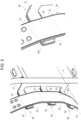
Figure 2 is the perspective view offigure 1 with parts removed for sake of clarity; -
Figure 3 is a perspective view of a catwalk step according to present invention; -
Figure 4 is a perspective view of a fixation element of the catwalk step according to the present invention; -
Figure 5 is a perspective view of a portion of the fixation element offigure 4 engaged to the catwalk step offigure 3 ; -
Figure 6 is a perspective view of a portion of the fixation element offigure 4 . -
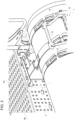
Figure 1 discloses a portion of a vehicle 1 essentially comprising a chassis frame2 and at least atank 3, e.g. a curved tank configured to store LNG for the operation of vehicle 1. - Vehicle 1 further comprises a
catwalk 5 carried bychassis 2 and preferably fixed to this latter in known way, e.g. by threaded means or by welding. Catwalk 5 may preferably comprise amain portion 6a, anauxiliary portion 6b and anaccess portion 7 positioned abovetank 3 and fixed tochassis 2 and to thestep 10 as disclosed in greater detail hereinafter. - Catwalk 5 may further comprise anti-slip means 8 configured to avoid the slipping of the user when walking on it in adverse atmospheric situations such as rain or ice. Such anti-slip means 8 may be for example a grip strut grating of known type.
- Vehicle 1 further comprises a
step 10 according to the present invention (figures 1 and3 ) configured to allow an user to get oncatwalk 5 and fixed totank 3 as described in the following. -
Step 10 essentially comprises aconnection portion 11 configured to cooperate withcatwalk 5, acoupling portion 12 configured to cooperate withtank 3 and astructural portion 13 connectingconnection portion 11 andcoupling portion 12 and allowing the user to get onstep 10 itself. -
Structural portion 13 comprises a pair ofpipes 15, e.g. rounded section pipes parallel to each other and at least onerung 16 connecting together the pair ofpipes 15. In the described embodiment, tworungs 16 are provided betweenpipes 15 and they moreover comprise, on their upper surface, anti-slip means 8 as the ones disclosed forcatwalk 5. Advantageously,pipes 15 andrungs 16 are realized as one piece and are made of steel. - Connection portion 11 (see
figure 2 ) may further comprise abracket 18 connected topipes 15 and configured to allow the fixation ofstep 10catwalk 5, preferably to accessportion 7.Bracket 18 may be fixed the upper terminal portions ofpipes 15.Bracket 18 may comprisefixation holes 19 to allow the fixation of the upper terminal portion ofpipes 15 to accessportion 7 in any known way, e.g. by threaded connections. -
Coupling portion 12 may comprise at least a pair offlanges 20 connected tostructural portion 13 and configured to cooperate with anexternal surface 3a oftank 3 in order to define a positive locking, i.e. a form fit, betweentank 3 andstep 10 so as to lock any vertical movement ofstep 10. - According to the present embodiment,
step 10 may comprise for eachpipe 15 threeflanges 20, in particular an upper bracket, a lower bracket and a bracket intermediate with respect to the upper and lower bracket. Advantageously at least two of these threeflanges 20 are positioned so that one of these two flanges exchange a force totank 3 which is directed to the ground and the other flange exchange a force totank 3 which is directed to the opposite direction of the force imparted by the first flange. - Each flange 20 (
figures 5 and6 ) comprises aspacer wall 21 connected topipe 15 and extending perpendicularly with respect to this latter towardstank 3 and acoupling wall 22 connected tospacer wall 21 and extending perpendicularly with respect to this latter and getting away frompipe 15.Spacer wall 21 is configured to define a distance, equal to its length, betweenpipe 15 andcoupling wall 22;coupling wall 22 is configured to cooperate withouter surface 3a oftank 3. -
Coupling wall 22 defines acoupling surface 22a configured to cooperate withouter surface 3a oftank 3. In the describedembodiment surface 22a is flat. It may be preferable thatsurface 22a is concave and it is curved in order to match withouter surface 3a oftank 3. -
Coupling wall 22 may further comprise a bendedextremity 23 configured to laterally cooperate with a band as described in greater detail in the following. -
Spacer wall 21,coupling wall 22 and bendedextremity 23 may advantageously be realized as one piece. - Each
flange 20 may further comprise apad 24 carried bycoupling wall 22 and configured to be interposed betweencoupling wall 22 andtank 3 to avoid a direct contact betweentank 3 andcoupling surface 22a so as to decrease risk of corrosion.Pad 24 may be realized in any electrical isolating material, e.g. EPDM (Ethylene-Propylene Diene Monomer).Pad 24 is advantageously realized in soft material in order to facilitate the cooperation between theouter surface 3a oftank 3 withflat surface 22a ofcoupling wall 22. - Advantageously, connecting
portion 11,coupling portion 12 andstructural portion 13 are welded together to realize a single piece. - According to the present invention,
step 10 is fixed totank 3 thanks to a friction engagement betweencoupling surface 22a given by a force acting oncoupling wall 22 directed towardstank 3. - According to the described embodiment,
step 10 further comprises atensioning belt 30 configured to impart the aforementioned force toflanges 20. Tensioning belt 30 (figure 3 ) is housed aroundtank 3 and lies oncoupling walls 22 of eachflange 20 so as to impart respective forces to these latter directed totank 3. Tensioning belt 30 (seefigure 4 ) is laterally retained by the respectivebended extremities 23 to one side and by therespective spacing walls 21 to the opposite one. -
Tensioning belt 30 preferably comprises at least astrap 31, in particular a singleflat strap 31 being opened and having twoextremities strap 31, as disclosed in the following. -
Strap 31 may advantageously comprise astructural layer 31a preferably made in metal, e.g. steel, and aninsulating layer 31b configured to avoid direct contact betweentank 3 andstructural layer 31a in order to decrease risk of corrosion.Insulation layer 31b may be realized in any isolating material, e.g. as previously mentioned EPDM. -
Extremities strap 31 on itself to producerespective eyelets eyelets 36, 37 afurther insulation layer 31b may be provide to avoid a direct contact withtank 3.Belt 31 may be refolded to itself by clinching so as to avoid belt corrosion. - Regulation means 34 preferably connects
eyelets extremities strap 31, will be modified accordingly. - According to the described embodiment, regulation means 34 may comprise a pair of
rods eyelets rod hole 40;respective holes 40 ofrods -
Holes 40 advantageously house anelement 41 having a portion of its outer surface which is threaded in order to operatively cooperate with thread ofholes 40 so that a rotation in one direction ofelement 41 makerods element 41 makerods - The operation of the
catwalk step 10 according to the present invention is the following. -
Step 10 is fixed in horizontal and lateral direction with respect longitudinal axis oftank 3 becausebelt 30 imparts respective forces directed towardstank 3 tocoupling elements 22 that, viapad 24, generates a friction engagement betweenstep 10 andtank 3. Such friction engagement may be regulated by reducing or increasing diameter ofbelt 30 via regulation means 34. - As already stated, the positioning of
flanges 20 aroundtank 3, i.e. the form-fit, guarantees a vertical fixation ofstep 10 ontank 3. - User may get on
stepwalk 5 supported bystep 10 thanks to the aforementioned attachment of this latter ontank 3 in all three axis. - The present invention is moreover directed to a method for attaching, and vice versa removing, a
catwalk step 10 as described above to atank 3 of a vehicle 1. - Such method for attaching a
catwalk step 10 essentially comprises the following steps: - Fixing the
structural portion 13 ofstep 10 to thecatwalk 5; - Matching the
coupling portion 12 ofstep 10 totank 3 to avoid vertical displacement ofstep 10 withrespect tank 3; - Positioning
slack tensioning belt 30 oncoupling portion 12; - Reducing perimeter of
belt 30 so as to impart a force to couplingportion 12 which can generate a friction engagement betweencoupling surface 22a andouter surface 3a oftank 3 so as to avoid horizontal and lateral displacement ofstep 10 withrespect tank 3. - For sake of brevity the removing method is not described, comprising essentially the same steps executed in inverse order.
- The reduction of length of
belt 30 is function of the material and geometry ofpad 24 andtank 3 and of the typology, material and geometry ofbelt 30. - In view of the foregoing, the advantages of a
catwalk step 10 according to the invention are apparent. - First, fixation of
catwalk step 10 to vehicle 1 is lighter, simpler and cheaper with respect to bolted or welded known fixations. - Moreover it is possible to attach
catwalk step 10 in different position with respect to vehicle 1 or to adjust the positioning of this latter, if needed. The attachment and removal method is simply and versatile and may be applied to different shapes oftanks 3 andstep 10. - Further, since direct contacts between metal of
tank 3 and metal ofbelt 30 orstep 10 is avoided, no corrosion incurs between the aforementioned elements. Such effect is moreover amplified because no welding or threaded elements are used. - Again, tank volume has not to be reduced to define steps in
tank 3 and step 10 may be used for any typology and dimension oftank 3 of the vehicle. - It is clear that modifications can be made to the described
catwalk step 10 which do not extend beyond the scope of protection defined by the claims. - For example, shapes of
step 10 andbelt 30 may be varied without departing from their functionalities. Therefore,belt 30 may comprisemore straps 31 being of different typologies than the above described one or step 10 may comprise a different number offlanges 20 orrungs 16 having a different shape. -
Tank 3 may be of any shape andcoupling portion 12 ofstep 10 may be varied accordingly to define a form fit. - Further, regulation means 34 may be substituted by any equivalent, e.g. an electrical or pneumatic actuator.
Claims (9)
- Catwalk step (10) for a vehicle (1) comprising a catwalk (5) and a tank (3), said step (10) comprising a structural portion (13) configured to allow the user to get on said catwalk (5) and a coupling portion (12) carried by said structural portion (13) and configured to match with an outer surface (3a) of said tank (3) and to cooperate by friction engagement with this latter so as to secure said step (10) on said tank (3) when a force directed towards said tank (3) is acting on said coupling portion (12), said coupling portion (12) comprising at least two flanges (20) coupled to said structural portion (13), each of said flanges (20) comprising at least a coupling wall (22) defining a surface (22a) configured to cooperate by friction engagement with said outer surface (3a) of said tank (3) in order to lock any lateral and horizontal displacement of said step (10) with respect to said tank (3), said flanges (20) defining a form-fit coupling with said tank (3) in order to lock any vertical displacement of said step (10) with respect to said tank (3), wherein said structural portion (13) comprises a pair of pipes (15) and at least one rung (16) connecting together said pipes (15), wherein each flange (20) comprises a spacer wall (21) connected to said pipe (15) and extending perpendicularly with respect to said pipe (15) towards said tank (3), said coupling wall (22) being connected to said spacer wall (21) and extending perpendicularly with respect to said spacer wall (21) getting away from said pipe (15).
- Catwalk step according to claim 1, wherein said step (10) further comprises a connection portion (11) carried by said structural portion (13) and configured to connect said step (10) to said catwalk (5)
- Catwalk step according to according to claim 1 or 2, wherein said step (10) comprises a pad (24) interposed between said coupling portion (12) and said tank (3).
- Catwalk step according to claim 3, wherein said pad (24) is made by EPDM.
- Catwalk step according to any of preceding claims, further comprising at least two tensioning belts (30) housed around said tank (3) and said coupling portion (12), each of said tensioning belts (30) being configured to impart to said coupling portion (12) said force.
- Catwalk step according to claim 5, wherein each of said tensioning belts (30) comprises at least one strap (31) whose length may be varied to vary said force imparted by tensioning belt (30) to coupling portion (12).
- Catwalk step according to claim 6, wherein said at least one strap (31) is opened and the extremities (32, 33) of said at least one strap (31) are connected together thanks to regulation means (34) to define a closed shape and configured to vary the perimeter of this latter.
- Catwalk step according to claim 7, wherein said regulation means (34) comprise a mechanical device configured to get said extremities (32, 33) closer each other or to get said extremities (32, 33) away each other so as to vary the perimeter of said closed shape.
- Method for attaching a catwalk step (10) according to any of claims 5 to 8, comprising the following steps:• Matching said coupling portion (12) to said tank (3) to avoid vertical displacement of step (10) with respect said tank (3);• Positioning slack tensioning belts (30) around said tank (3) and on said coupling portion (12);• Reducing length of belts (30) so as to impart a force to coupling portion (12) which can generate a friction engagement between coupling surface (22a) and outer surface (3a) of tank (3) so as to avoid horizontal and lateral displacement of step (10) with respect tank (3).
Applications Claiming Priority (1)
| Application Number | Priority Date | Filing Date | Title |
|---|---|---|---|
| IT201800002116A IT201800002116A1 (en) | 2018-01-29 | 2018-01-29 | LADDER FOR GANGWAY OF A VEHICLE |
Publications (3)
| Publication Number | Publication Date |
|---|---|
| EP3517365A1 EP3517365A1 (en) | 2019-07-31 |
| EP3517365B1 EP3517365B1 (en) | 2020-11-25 |
| EP3517365B2 true EP3517365B2 (en) | 2023-11-15 |
Family
ID=61952916
Family Applications (1)
| Application Number | Title | Priority Date | Filing Date |
|---|---|---|---|
| EP19154341.2A Active EP3517365B2 (en) | 2018-01-29 | 2019-01-29 | Catwalk step for a vehicle |
Country Status (3)
| Country | Link |
|---|---|
| EP (1) | EP3517365B2 (en) |
| ES (1) | ES2846778T5 (en) |
| IT (1) | IT201800002116A1 (en) |
Family Cites Families (5)
| Publication number | Priority date | Publication date | Assignee | Title |
|---|---|---|---|---|
| US4102432A (en) * | 1977-02-11 | 1978-07-25 | Leopold Bustin | Step mounting structure for vehicle tanks |
| DE10033386B4 (en) * | 2000-07-08 | 2009-09-24 | Man Nutzfahrzeuge Ag | Ascent to committing a commercial vehicle |
| DE102006028567A1 (en) * | 2006-06-22 | 2008-01-03 | Daimlerchrysler Ag | Modular system for e.g. lorry, has carrier module for energy source of vehicle, and auxiliary tank arranged at fuel tank of vehicle to accommodate auxiliary liquid, where auxiliary tank is positioned below carrier module |
| DE102008058387A1 (en) * | 2008-11-21 | 2009-06-18 | Daimler Ag | Step tread for use in commercial motor vehicle tank, has section forming supporting device extending away from horizontal rectangular tread surface, where supporting device is supported on supporting surface |
| GB2510683A (en) * | 2013-12-10 | 2014-08-13 | Daimler Ag | Fuel tank mounting arrangement with step assembly |
-
2018
- 2018-01-29 IT IT201800002116A patent/IT201800002116A1/en unknown
-
2019
- 2019-01-29 EP EP19154341.2A patent/EP3517365B2/en active Active
- 2019-01-29 ES ES19154341T patent/ES2846778T5/en active Active
Also Published As
| Publication number | Publication date |
|---|---|
| ES2846778T3 (en) | 2021-07-29 |
| ES2846778T5 (en) | 2024-05-28 |
| IT201800002116A1 (en) | 2019-07-29 |
| EP3517365B1 (en) | 2020-11-25 |
| EP3517365A1 (en) | 2019-07-31 |
Similar Documents
| Publication | Publication Date | Title |
|---|---|---|
| KR100941255B1 (en) | Trailing arm mounting device for small frame vehicles | |
| US20150008654A1 (en) | Single-Shell Spring Arm | |
| EP3517365B2 (en) | Catwalk step for a vehicle | |
| US7726718B2 (en) | Structural support for a bolt collar | |
| US9096108B2 (en) | Wheel axle suspension | |
| WO2017095295A1 (en) | Attachment arrangement for a band-shaped tightening strap | |
| US9446794B2 (en) | Fender panel support structure for vehicle | |
| US11938778B2 (en) | Sway bar clamp | |
| US20050121875A1 (en) | Strut/shock crossmember | |
| CN104527788A (en) | Subframe structure | |
| US10486482B2 (en) | Axle unit | |
| MX2014008421A (en) | Slider pin assembly with integral inboard and outboard stop. | |
| CA3020668A1 (en) | Frame unit | |
| US20060125202A1 (en) | Mounting structure of stabilizer bar in vehicle | |
| US8276981B2 (en) | Frame arrangement for a vehicle | |
| US11787256B2 (en) | Stabilizing bar for a vehicle | |
| CN107405972B (en) | Method for reinforcing the attachment of a cross member on a trailing arm of a semi-rigid axle | |
| WO2014178769A1 (en) | Spring suspension | |
| JP2015131592A (en) | Reinforcing structure of crossmemebr for vehicle | |
| EP3219585B1 (en) | A chassis for a trailer | |
| JP4728574B2 (en) | Cross member height adjustment plate | |
| CN115443224A (en) | Forged flexible trailing arm with omega-shaped cross-section | |
| US10293652B2 (en) | Axle unit | |
| US20230067772A1 (en) | Steering knuckle | |
| US20180265184A1 (en) | Aircraft landing gear assembly |
Legal Events
| Date | Code | Title | Description |
|---|---|---|---|
| PUAI | Public reference made under article 153(3) epc to a published international application that has entered the european phase |
Free format text: ORIGINAL CODE: 0009012 |
|
| STAA | Information on the status of an ep patent application or granted ep patent |
Free format text: STATUS: THE APPLICATION HAS BEEN PUBLISHED |
|
| AK | Designated contracting states |
Kind code of ref document: A1 Designated state(s): AL AT BE BG CH CY CZ DE DK EE ES FI FR GB GR HR HU IE IS IT LI LT LU LV MC MK MT NL NO PL PT RO RS SE SI SK SM TR |
|
| AX | Request for extension of the european patent |
Extension state: BA ME |
|
| STAA | Information on the status of an ep patent application or granted ep patent |
Free format text: STATUS: REQUEST FOR EXAMINATION WAS MADE |
|
| 17P | Request for examination filed |
Effective date: 20200114 |
|
| RBV | Designated contracting states (corrected) |
Designated state(s): AL AT BE BG CH CY CZ DE DK EE ES FI FR GB GR HR HU IE IS IT LI LT LU LV MC MK MT NL NO PL PT RO RS SE SI SK SM TR |
|
| GRAP | Despatch of communication of intention to grant a patent |
Free format text: ORIGINAL CODE: EPIDOSNIGR1 |
|
| STAA | Information on the status of an ep patent application or granted ep patent |
Free format text: STATUS: GRANT OF PATENT IS INTENDED |
|
| INTG | Intention to grant announced |
Effective date: 20200619 |
|
| GRAS | Grant fee paid |
Free format text: ORIGINAL CODE: EPIDOSNIGR3 |
|
| GRAA | (expected) grant |
Free format text: ORIGINAL CODE: 0009210 |
|
| STAA | Information on the status of an ep patent application or granted ep patent |
Free format text: STATUS: THE PATENT HAS BEEN GRANTED |
|
| AK | Designated contracting states |
Kind code of ref document: B1 Designated state(s): AL AT BE BG CH CY CZ DE DK EE ES FI FR GB GR HR HU IE IS IT LI LT LU LV MC MK MT NL NO PL PT RO RS SE SI SK SM TR |
|
| REG | Reference to a national code |
Ref country code: GB Ref legal event code: FG4D |
|
| REG | Reference to a national code |
Ref country code: CH Ref legal event code: EP |
|
| REG | Reference to a national code |
Ref country code: DE Ref legal event code: R096 Ref document number: 602019001400 Country of ref document: DE |
|
| REG | Reference to a national code |
Ref country code: AT Ref legal event code: REF Ref document number: 1337922 Country of ref document: AT Kind code of ref document: T Effective date: 20201215 |
|
| REG | Reference to a national code |
Ref country code: IE Ref legal event code: FG4D |
|
| REG | Reference to a national code |
Ref country code: AT Ref legal event code: MK05 Ref document number: 1337922 Country of ref document: AT Kind code of ref document: T Effective date: 20201125 |
|
| REG | Reference to a national code |
Ref country code: NL Ref legal event code: MP Effective date: 20201125 |
|
| PG25 | Lapsed in a contracting state [announced via postgrant information from national office to epo] |
Ref country code: FI Free format text: LAPSE BECAUSE OF FAILURE TO SUBMIT A TRANSLATION OF THE DESCRIPTION OR TO PAY THE FEE WITHIN THE PRESCRIBED TIME-LIMIT Effective date: 20201125 Ref country code: RS Free format text: LAPSE BECAUSE OF FAILURE TO SUBMIT A TRANSLATION OF THE DESCRIPTION OR TO PAY THE FEE WITHIN THE PRESCRIBED TIME-LIMIT Effective date: 20201125 Ref country code: PT Free format text: LAPSE BECAUSE OF FAILURE TO SUBMIT A TRANSLATION OF THE DESCRIPTION OR TO PAY THE FEE WITHIN THE PRESCRIBED TIME-LIMIT Effective date: 20210325 Ref country code: NO Free format text: LAPSE BECAUSE OF FAILURE TO SUBMIT A TRANSLATION OF THE DESCRIPTION OR TO PAY THE FEE WITHIN THE PRESCRIBED TIME-LIMIT Effective date: 20210225 Ref country code: GR Free format text: LAPSE BECAUSE OF FAILURE TO SUBMIT A TRANSLATION OF THE DESCRIPTION OR TO PAY THE FEE WITHIN THE PRESCRIBED TIME-LIMIT Effective date: 20210226 |
|
| PG25 | Lapsed in a contracting state [announced via postgrant information from national office to epo] |
Ref country code: IS Free format text: LAPSE BECAUSE OF FAILURE TO SUBMIT A TRANSLATION OF THE DESCRIPTION OR TO PAY THE FEE WITHIN THE PRESCRIBED TIME-LIMIT Effective date: 20210325 Ref country code: LV Free format text: LAPSE BECAUSE OF FAILURE TO SUBMIT A TRANSLATION OF THE DESCRIPTION OR TO PAY THE FEE WITHIN THE PRESCRIBED TIME-LIMIT Effective date: 20201125 Ref country code: PL Free format text: LAPSE BECAUSE OF FAILURE TO SUBMIT A TRANSLATION OF THE DESCRIPTION OR TO PAY THE FEE WITHIN THE PRESCRIBED TIME-LIMIT Effective date: 20201125 Ref country code: SE Free format text: LAPSE BECAUSE OF FAILURE TO SUBMIT A TRANSLATION OF THE DESCRIPTION OR TO PAY THE FEE WITHIN THE PRESCRIBED TIME-LIMIT Effective date: 20201125 Ref country code: BG Free format text: LAPSE BECAUSE OF FAILURE TO SUBMIT A TRANSLATION OF THE DESCRIPTION OR TO PAY THE FEE WITHIN THE PRESCRIBED TIME-LIMIT Effective date: 20210225 Ref country code: AT Free format text: LAPSE BECAUSE OF FAILURE TO SUBMIT A TRANSLATION OF THE DESCRIPTION OR TO PAY THE FEE WITHIN THE PRESCRIBED TIME-LIMIT Effective date: 20201125 |
|
| REG | Reference to a national code |
Ref country code: LT Ref legal event code: MG9D |
|
| PG25 | Lapsed in a contracting state [announced via postgrant information from national office to epo] |
Ref country code: HR Free format text: LAPSE BECAUSE OF FAILURE TO SUBMIT A TRANSLATION OF THE DESCRIPTION OR TO PAY THE FEE WITHIN THE PRESCRIBED TIME-LIMIT Effective date: 20201125 |
|
| REG | Reference to a national code |
Ref country code: ES Ref legal event code: FG2A Ref document number: 2846778 Country of ref document: ES Kind code of ref document: T3 Effective date: 20210729 |
|
| PG25 | Lapsed in a contracting state [announced via postgrant information from national office to epo] |
Ref country code: RO Free format text: LAPSE BECAUSE OF FAILURE TO SUBMIT A TRANSLATION OF THE DESCRIPTION OR TO PAY THE FEE WITHIN THE PRESCRIBED TIME-LIMIT Effective date: 20201125 Ref country code: LT Free format text: LAPSE BECAUSE OF FAILURE TO SUBMIT A TRANSLATION OF THE DESCRIPTION OR TO PAY THE FEE WITHIN THE PRESCRIBED TIME-LIMIT Effective date: 20201125 Ref country code: CZ Free format text: LAPSE BECAUSE OF FAILURE TO SUBMIT A TRANSLATION OF THE DESCRIPTION OR TO PAY THE FEE WITHIN THE PRESCRIBED TIME-LIMIT Effective date: 20201125 Ref country code: EE Free format text: LAPSE BECAUSE OF FAILURE TO SUBMIT A TRANSLATION OF THE DESCRIPTION OR TO PAY THE FEE WITHIN THE PRESCRIBED TIME-LIMIT Effective date: 20201125 Ref country code: SM Free format text: LAPSE BECAUSE OF FAILURE TO SUBMIT A TRANSLATION OF THE DESCRIPTION OR TO PAY THE FEE WITHIN THE PRESCRIBED TIME-LIMIT Effective date: 20201125 Ref country code: SK Free format text: LAPSE BECAUSE OF FAILURE TO SUBMIT A TRANSLATION OF THE DESCRIPTION OR TO PAY THE FEE WITHIN THE PRESCRIBED TIME-LIMIT Effective date: 20201125 |
|
| REG | Reference to a national code |
Ref country code: DE Ref legal event code: R026 Ref document number: 602019001400 Country of ref document: DE |
|
| PLBI | Opposition filed |
Free format text: ORIGINAL CODE: 0009260 |
|
| PG25 | Lapsed in a contracting state [announced via postgrant information from national office to epo] |
Ref country code: DK Free format text: LAPSE BECAUSE OF FAILURE TO SUBMIT A TRANSLATION OF THE DESCRIPTION OR TO PAY THE FEE WITHIN THE PRESCRIBED TIME-LIMIT Effective date: 20201125 Ref country code: MC Free format text: LAPSE BECAUSE OF FAILURE TO SUBMIT A TRANSLATION OF THE DESCRIPTION OR TO PAY THE FEE WITHIN THE PRESCRIBED TIME-LIMIT Effective date: 20201125 |
|
| PLAX | Notice of opposition and request to file observation + time limit sent |
Free format text: ORIGINAL CODE: EPIDOSNOBS2 |
|
| 26 | Opposition filed |
Opponent name: SCANIA CV AB Effective date: 20210820 |
|
| PG25 | Lapsed in a contracting state [announced via postgrant information from national office to epo] |
Ref country code: LU Free format text: LAPSE BECAUSE OF NON-PAYMENT OF DUE FEES Effective date: 20210129 |
|
| REG | Reference to a national code |
Ref country code: BE Ref legal event code: MM Effective date: 20210131 |
|
| PG25 | Lapsed in a contracting state [announced via postgrant information from national office to epo] |
Ref country code: NL Free format text: LAPSE BECAUSE OF FAILURE TO SUBMIT A TRANSLATION OF THE DESCRIPTION OR TO PAY THE FEE WITHIN THE PRESCRIBED TIME-LIMIT Effective date: 20201125 Ref country code: AL Free format text: LAPSE BECAUSE OF FAILURE TO SUBMIT A TRANSLATION OF THE DESCRIPTION OR TO PAY THE FEE WITHIN THE PRESCRIBED TIME-LIMIT Effective date: 20201125 |
|
| PG25 | Lapsed in a contracting state [announced via postgrant information from national office to epo] |
Ref country code: SI Free format text: LAPSE BECAUSE OF FAILURE TO SUBMIT A TRANSLATION OF THE DESCRIPTION OR TO PAY THE FEE WITHIN THE PRESCRIBED TIME-LIMIT Effective date: 20201125 |
|
| PLAB | Opposition data, opponent's data or that of the opponent's representative modified |
Free format text: ORIGINAL CODE: 0009299OPPO |
|
| PLBB | Reply of patent proprietor to notice(s) of opposition received |
Free format text: ORIGINAL CODE: EPIDOSNOBS3 |
|
| R26 | Opposition filed (corrected) |
Opponent name: SCANIA CV AB Effective date: 20210820 |
|
| PG25 | Lapsed in a contracting state [announced via postgrant information from national office to epo] |
Ref country code: IE Free format text: LAPSE BECAUSE OF NON-PAYMENT OF DUE FEES Effective date: 20210129 |
|
| PG25 | Lapsed in a contracting state [announced via postgrant information from national office to epo] |
Ref country code: IS Free format text: LAPSE BECAUSE OF FAILURE TO SUBMIT A TRANSLATION OF THE DESCRIPTION OR TO PAY THE FEE WITHIN THE PRESCRIBED TIME-LIMIT Effective date: 20210325 |
|
| PG25 | Lapsed in a contracting state [announced via postgrant information from national office to epo] |
Ref country code: BE Free format text: LAPSE BECAUSE OF NON-PAYMENT OF DUE FEES Effective date: 20210131 |
|
| REG | Reference to a national code |
Ref country code: CH Ref legal event code: PL |
|
| PG25 | Lapsed in a contracting state [announced via postgrant information from national office to epo] |
Ref country code: LI Free format text: LAPSE BECAUSE OF NON-PAYMENT OF DUE FEES Effective date: 20220131 Ref country code: CH Free format text: LAPSE BECAUSE OF NON-PAYMENT OF DUE FEES Effective date: 20220131 |
|
| APBM | Appeal reference recorded |
Free format text: ORIGINAL CODE: EPIDOSNREFNO |
|
| APBP | Date of receipt of notice of appeal recorded |
Free format text: ORIGINAL CODE: EPIDOSNNOA2O |
|
| APAH | Appeal reference modified |
Free format text: ORIGINAL CODE: EPIDOSCREFNO |
|
| P01 | Opt-out of the competence of the unified patent court (upc) registered |
Effective date: 20230522 |
|
| PG25 | Lapsed in a contracting state [announced via postgrant information from national office to epo] |
Ref country code: CY Free format text: LAPSE BECAUSE OF FAILURE TO SUBMIT A TRANSLATION OF THE DESCRIPTION OR TO PAY THE FEE WITHIN THE PRESCRIBED TIME-LIMIT Effective date: 20201125 |
|
| APBU | Appeal procedure closed |
Free format text: ORIGINAL CODE: EPIDOSNNOA9O |
|
| PG25 | Lapsed in a contracting state [announced via postgrant information from national office to epo] |
Ref country code: HU Free format text: LAPSE BECAUSE OF FAILURE TO SUBMIT A TRANSLATION OF THE DESCRIPTION OR TO PAY THE FEE WITHIN THE PRESCRIBED TIME-LIMIT; INVALID AB INITIO Effective date: 20190129 |
|
| PUAH | Patent maintained in amended form |
Free format text: ORIGINAL CODE: 0009272 |
|
| STAA | Information on the status of an ep patent application or granted ep patent |
Free format text: STATUS: PATENT MAINTAINED AS AMENDED |
|
| 27A | Patent maintained in amended form |
Effective date: 20231115 |
|
| AK | Designated contracting states |
Kind code of ref document: B2 Designated state(s): AL AT BE BG CH CY CZ DE DK EE ES FI FR GB GR HR HU IE IS IT LI LT LU LV MC MK MT NL NO PL PT RO RS SE SI SK SM TR |
|
| REG | Reference to a national code |
Ref country code: DE Ref legal event code: R102 Ref document number: 602019001400 Country of ref document: DE |
|
| PG25 | Lapsed in a contracting state [announced via postgrant information from national office to epo] |
Ref country code: MK Free format text: LAPSE BECAUSE OF FAILURE TO SUBMIT A TRANSLATION OF THE DESCRIPTION OR TO PAY THE FEE WITHIN THE PRESCRIBED TIME-LIMIT Effective date: 20201125 |
|
| REG | Reference to a national code |
Ref country code: ES Ref legal event code: DC2A Ref document number: 2846778 Country of ref document: ES Kind code of ref document: T5 Effective date: 20240528 |
|
| PG25 | Lapsed in a contracting state [announced via postgrant information from national office to epo] |
Ref country code: TR Free format text: LAPSE BECAUSE OF FAILURE TO SUBMIT A TRANSLATION OF THE DESCRIPTION OR TO PAY THE FEE WITHIN THE PRESCRIBED TIME-LIMIT Effective date: 20201125 |
|
| PG25 | Lapsed in a contracting state [announced via postgrant information from national office to epo] |
Ref country code: MT Free format text: LAPSE BECAUSE OF FAILURE TO SUBMIT A TRANSLATION OF THE DESCRIPTION OR TO PAY THE FEE WITHIN THE PRESCRIBED TIME-LIMIT Effective date: 20201125 |
|
| PGFP | Annual fee paid to national office [announced via postgrant information from national office to epo] |
Ref country code: DE Payment date: 20250129 Year of fee payment: 7 |
|
| PGFP | Annual fee paid to national office [announced via postgrant information from national office to epo] |
Ref country code: ES Payment date: 20250210 Year of fee payment: 7 |
|
| PGFP | Annual fee paid to national office [announced via postgrant information from national office to epo] |
Ref country code: FR Payment date: 20250127 Year of fee payment: 7 |
|
| PGFP | Annual fee paid to national office [announced via postgrant information from national office to epo] |
Ref country code: GB Payment date: 20250121 Year of fee payment: 7 Ref country code: IT Payment date: 20250110 Year of fee payment: 7 |