EP3517350A1 - Wireless battery management system and battery pack including same - Google Patents
Wireless battery management system and battery pack including same Download PDFInfo
- Publication number
- EP3517350A1 EP3517350A1 EP18834826.2A EP18834826A EP3517350A1 EP 3517350 A1 EP3517350 A1 EP 3517350A1 EP 18834826 A EP18834826 A EP 18834826A EP 3517350 A1 EP3517350 A1 EP 3517350A1
- Authority
- EP
- European Patent Office
- Prior art keywords
- battery
- balancing
- wireless
- module
- cell
- Prior art date
- Legal status (The legal status is an assumption and is not a legal conclusion. Google has not performed a legal analysis and makes no representation as to the accuracy of the status listed.)
- Pending
Links
Images




Classifications
-
- H—ELECTRICITY
- H02—GENERATION; CONVERSION OR DISTRIBUTION OF ELECTRIC POWER
- H02J—ELECTRIC POWER NETWORKS; CIRCUIT ARRANGEMENTS OR SYSTEMS FOR SUPPLYING OR DISTRIBUTING ELECTRIC POWER; SYSTEMS FOR STORING ELECTRIC ENERGY
- H02J7/00—Circuit arrangements for charging or discharging batteries or for supplying loads from batteries
- H02J7/50—Circuit arrangements for charging or discharging batteries or for supplying loads from batteries acting upon multiple batteries simultaneously or sequentially
- H02J7/52—Circuit arrangements for charging or discharging batteries or for supplying loads from batteries acting upon multiple batteries simultaneously or sequentially for charge balancing, e.g. equalisation of charge between batteries
-
- B—PERFORMING OPERATIONS; TRANSPORTING
- B60—VEHICLES IN GENERAL
- B60L—PROPULSION OF ELECTRICALLY-PROPELLED VEHICLES; SUPPLYING ELECTRIC POWER FOR AUXILIARY EQUIPMENT OF ELECTRICALLY-PROPELLED VEHICLES; ELECTRODYNAMIC BRAKE SYSTEMS FOR VEHICLES IN GENERAL; MAGNETIC SUSPENSION OR LEVITATION FOR VEHICLES; MONITORING OPERATING VARIABLES OF ELECTRICALLY-PROPELLED VEHICLES; ELECTRIC SAFETY DEVICES FOR ELECTRICALLY-PROPELLED VEHICLES
- B60L50/00—Electric propulsion with power supplied within the vehicle
- B60L50/50—Electric propulsion with power supplied within the vehicle using propulsion power supplied by batteries or fuel cells
-
- B—PERFORMING OPERATIONS; TRANSPORTING
- B60—VEHICLES IN GENERAL
- B60L—PROPULSION OF ELECTRICALLY-PROPELLED VEHICLES; SUPPLYING ELECTRIC POWER FOR AUXILIARY EQUIPMENT OF ELECTRICALLY-PROPELLED VEHICLES; ELECTRODYNAMIC BRAKE SYSTEMS FOR VEHICLES IN GENERAL; MAGNETIC SUSPENSION OR LEVITATION FOR VEHICLES; MONITORING OPERATING VARIABLES OF ELECTRICALLY-PROPELLED VEHICLES; ELECTRIC SAFETY DEVICES FOR ELECTRICALLY-PROPELLED VEHICLES
- B60L58/00—Methods or circuit arrangements for monitoring or controlling batteries or fuel cells, specially adapted for electric vehicles
- B60L58/10—Methods or circuit arrangements for monitoring or controlling batteries or fuel cells, specially adapted for electric vehicles for monitoring or controlling batteries
- B60L58/12—Methods or circuit arrangements for monitoring or controlling batteries or fuel cells, specially adapted for electric vehicles for monitoring or controlling batteries responding to state of charge [SoC]
-
- B—PERFORMING OPERATIONS; TRANSPORTING
- B60—VEHICLES IN GENERAL
- B60L—PROPULSION OF ELECTRICALLY-PROPELLED VEHICLES; SUPPLYING ELECTRIC POWER FOR AUXILIARY EQUIPMENT OF ELECTRICALLY-PROPELLED VEHICLES; ELECTRODYNAMIC BRAKE SYSTEMS FOR VEHICLES IN GENERAL; MAGNETIC SUSPENSION OR LEVITATION FOR VEHICLES; MONITORING OPERATING VARIABLES OF ELECTRICALLY-PROPELLED VEHICLES; ELECTRIC SAFETY DEVICES FOR ELECTRICALLY-PROPELLED VEHICLES
- B60L58/00—Methods or circuit arrangements for monitoring or controlling batteries or fuel cells, specially adapted for electric vehicles
- B60L58/10—Methods or circuit arrangements for monitoring or controlling batteries or fuel cells, specially adapted for electric vehicles for monitoring or controlling batteries
- B60L58/18—Methods or circuit arrangements for monitoring or controlling batteries or fuel cells, specially adapted for electric vehicles for monitoring or controlling batteries of two or more battery modules
- B60L58/22—Balancing the charge of battery modules
-
- G—PHYSICS
- G01—MEASURING; TESTING
- G01R—MEASURING ELECTRIC VARIABLES; MEASURING MAGNETIC VARIABLES
- G01R31/00—Arrangements for testing electric properties; Arrangements for locating electric faults; Arrangements for electrical testing characterised by what is being tested not provided for elsewhere
- G01R31/36—Arrangements for testing, measuring or monitoring the electrical condition of accumulators or electric batteries, e.g. capacity or state of charge [SoC]
- G01R31/3644—Constructional arrangements
- G01R31/3648—Constructional arrangements comprising digital calculation means, e.g. for performing an algorithm
-
- G—PHYSICS
- G01—MEASURING; TESTING
- G01R—MEASURING ELECTRIC VARIABLES; MEASURING MAGNETIC VARIABLES
- G01R31/00—Arrangements for testing electric properties; Arrangements for locating electric faults; Arrangements for electrical testing characterised by what is being tested not provided for elsewhere
- G01R31/36—Arrangements for testing, measuring or monitoring the electrical condition of accumulators or electric batteries, e.g. capacity or state of charge [SoC]
- G01R31/382—Arrangements for monitoring battery or accumulator variables, e.g. SoC
-
- H—ELECTRICITY
- H01—ELECTRIC ELEMENTS
- H01M—PROCESSES OR MEANS, e.g. BATTERIES, FOR THE DIRECT CONVERSION OF CHEMICAL ENERGY INTO ELECTRICAL ENERGY
- H01M10/00—Secondary cells; Manufacture thereof
- H01M10/42—Methods or arrangements for servicing or maintenance of secondary cells or secondary half-cells
-
- H—ELECTRICITY
- H01—ELECTRIC ELEMENTS
- H01M—PROCESSES OR MEANS, e.g. BATTERIES, FOR THE DIRECT CONVERSION OF CHEMICAL ENERGY INTO ELECTRICAL ENERGY
- H01M10/00—Secondary cells; Manufacture thereof
- H01M10/42—Methods or arrangements for servicing or maintenance of secondary cells or secondary half-cells
- H01M10/48—Accumulators combined with arrangements for measuring, testing or indicating the condition of cells, e.g. the level or density of the electrolyte
- H01M10/482—Accumulators combined with arrangements for measuring, testing or indicating the condition of cells, e.g. the level or density of the electrolyte for several batteries or cells simultaneously or sequentially
-
- H—ELECTRICITY
- H02—GENERATION; CONVERSION OR DISTRIBUTION OF ELECTRIC POWER
- H02J—ELECTRIC POWER NETWORKS; CIRCUIT ARRANGEMENTS OR SYSTEMS FOR SUPPLYING OR DISTRIBUTING ELECTRIC POWER; SYSTEMS FOR STORING ELECTRIC ENERGY
- H02J7/00—Circuit arrangements for charging or discharging batteries or for supplying loads from batteries
-
- H—ELECTRICITY
- H04—ELECTRIC COMMUNICATION TECHNIQUE
- H04W—WIRELESS COMMUNICATION NETWORKS
- H04W84/00—Network topologies
-
- B—PERFORMING OPERATIONS; TRANSPORTING
- B60—VEHICLES IN GENERAL
- B60L—PROPULSION OF ELECTRICALLY-PROPELLED VEHICLES; SUPPLYING ELECTRIC POWER FOR AUXILIARY EQUIPMENT OF ELECTRICALLY-PROPELLED VEHICLES; ELECTRODYNAMIC BRAKE SYSTEMS FOR VEHICLES IN GENERAL; MAGNETIC SUSPENSION OR LEVITATION FOR VEHICLES; MONITORING OPERATING VARIABLES OF ELECTRICALLY-PROPELLED VEHICLES; ELECTRIC SAFETY DEVICES FOR ELECTRICALLY-PROPELLED VEHICLES
- B60L2260/00—Operating Modes
- B60L2260/40—Control modes
- B60L2260/50—Control modes by future state prediction
- B60L2260/54—Energy consumption estimation
-
- H—ELECTRICITY
- H01—ELECTRIC ELEMENTS
- H01M—PROCESSES OR MEANS, e.g. BATTERIES, FOR THE DIRECT CONVERSION OF CHEMICAL ENERGY INTO ELECTRICAL ENERGY
- H01M10/00—Secondary cells; Manufacture thereof
- H01M10/42—Methods or arrangements for servicing or maintenance of secondary cells or secondary half-cells
- H01M10/425—Structural combination with electronic components, e.g. electronic circuits integrated to the outside of the casing
- H01M2010/4271—Battery management systems including electronic circuits, e.g. control of current or voltage to keep battery in healthy state, cell balancing
-
- Y—GENERAL TAGGING OF NEW TECHNOLOGICAL DEVELOPMENTS; GENERAL TAGGING OF CROSS-SECTIONAL TECHNOLOGIES SPANNING OVER SEVERAL SECTIONS OF THE IPC; TECHNICAL SUBJECTS COVERED BY FORMER USPC CROSS-REFERENCE ART COLLECTIONS [XRACs] AND DIGESTS
- Y02—TECHNOLOGIES OR APPLICATIONS FOR MITIGATION OR ADAPTATION AGAINST CLIMATE CHANGE
- Y02E—REDUCTION OF GREENHOUSE GAS [GHG] EMISSIONS, RELATED TO ENERGY GENERATION, TRANSMISSION OR DISTRIBUTION
- Y02E60/00—Enabling technologies; Technologies with a potential or indirect contribution to GHG emissions mitigation
- Y02E60/10—Energy storage using batteries
-
- Y—GENERAL TAGGING OF NEW TECHNOLOGICAL DEVELOPMENTS; GENERAL TAGGING OF CROSS-SECTIONAL TECHNOLOGIES SPANNING OVER SEVERAL SECTIONS OF THE IPC; TECHNICAL SUBJECTS COVERED BY FORMER USPC CROSS-REFERENCE ART COLLECTIONS [XRACs] AND DIGESTS
- Y02—TECHNOLOGIES OR APPLICATIONS FOR MITIGATION OR ADAPTATION AGAINST CLIMATE CHANGE
- Y02T—CLIMATE CHANGE MITIGATION TECHNOLOGIES RELATED TO TRANSPORTATION
- Y02T10/00—Road transport of goods or passengers
- Y02T10/60—Other road transportation technologies with climate change mitigation effect
- Y02T10/70—Energy storage systems for electromobility, e.g. batteries
-
- Y—GENERAL TAGGING OF NEW TECHNOLOGICAL DEVELOPMENTS; GENERAL TAGGING OF CROSS-SECTIONAL TECHNOLOGIES SPANNING OVER SEVERAL SECTIONS OF THE IPC; TECHNICAL SUBJECTS COVERED BY FORMER USPC CROSS-REFERENCE ART COLLECTIONS [XRACs] AND DIGESTS
- Y02—TECHNOLOGIES OR APPLICATIONS FOR MITIGATION OR ADAPTATION AGAINST CLIMATE CHANGE
- Y02T—CLIMATE CHANGE MITIGATION TECHNOLOGIES RELATED TO TRANSPORTATION
- Y02T90/00—Enabling technologies or technologies with a potential or indirect contribution to GHG emissions mitigation
- Y02T90/10—Technologies relating to charging of electric vehicles
- Y02T90/16—Information or communication technologies improving the operation of electric vehicles
Definitions
- the present disclosure relates to a wireless battery management system, and more particularly, to a wireless battery management system for reducing a residual capacity deviation between battery modules and a battery pack including the same.
- a battery pack applied to electric vehicles generally includes a plurality of battery modules connected in series and a plurality of battery management systems (BMSs). Each BMS monitors and controls the state of the battery module that the BMU manages. Recently, to meet the demand for high-capacity high-output battery packs, the number of battery modules included in a battery pack also increases. To efficiently manage the state of each battery module included in the battery pack, a single master-multi slave structure is disclosed.
- the single master-multi slave structure includes a plurality of slave BMSs installed in each battery module and a master BMS that controls the overall operation of the plurality of slave BMSs. In this instance, communication between the plurality of slave BMSs and the master BMS may be performed by a wireless method.
- Each of the plurality of slave BMSs transmits a wireless signal to the master BMS or receives a wireless signal from the master BMS using electrical energy of the battery module in which the slave BMS is coupled.
- the present disclosure is directed to providing a wireless battery management system for performing module balancing to reduce a residual capacity deviation between battery modules by transmitting a radio frequency (RF) signal through a non-communication wireless channel using electrical energy of at least one of the battery modules, and a battery pack including the same.
- RF radio frequency
- a wireless battery management system includes a master BMS configured to transmit a first radio frequency (RF) signal including a state detection command through a first wireless channel.
- the wireless battery management system further includes a plurality of slave BMSs coupled to a plurality of battery modules in one-to-one correspondence.
- Each of the plurality of slave BMSs is configured to detect state information of the battery module to which the corresponding slave BMS is coupled in response to the first RF signal, and transmit a second RF signal indicating the state information of the battery module through the first wireless channel.
- the master BMS is configured to determine a wireless balancing time for each of the plurality of battery modules based on the second RF signal, and transmit a third RF signal including a module balancing command indicating the wireless balancing time to the plurality of slave BMSs through the first wireless channel.
- Each of the plurality of slave BMSs is configured to transmit a fourth RF signal through a second wireless channel during the wireless balancing time using electrical energy of the battery module to which the corresponding slave BMS is coupled according to the module balancing command included in the third RF signal.
- the first wireless channel may have a preset first frequency range.
- the second wireless channel may have a preset second frequency range that is separated from the first frequency range.
- the master BMS may calculate a module residual capacity stored in each of the plurality of battery modules based on the second RF signal, and determine the wireless balancing time for each of the plurality of battery modules based on the module residual capacity of each of the plurality of battery modules.
- the master BMS may set the module residual capacity of one of the plurality of battery modules as a first target residual capacity, and determine the wireless balancing time for each of the plurality of battery modules based on a difference between the first target residual capacity and each of the other module residual capacities.
- the state information of the battery module may include state information of each battery cell included in the battery module.
- the master BMS may calculate a cell residual capacity of each battery cell included in each of the plurality of battery modules based on the second RF signal, and determine the wireless balancing time for each of the plurality of battery modules based on the cell residual capacity of each battery cell included in each of the plurality of battery modules.
- the master BMS may determine a smallest cell residual capacity of cell residual capacities of all battery cells included in the plurality of battery modules as second target residual capacity, and determine the wireless balancing time for each of the plurality of battery modules further based on a difference between the second target residual capacity and the minimum cell residual capacity of each of the other battery modules.
- the master BMS may determine a wired balancing time for each battery cell included in each of the plurality of battery modules based on a difference between the minimum cell residual capacity of each of the plurality of battery modules and each of the other cell residual capacities.
- the third RF signal may further include a cell balancing command indicating the wired balancing time.
- Each of the plurality of slave BMSs may include a wired balancing unit electrically connected to two ends of each battery cell included in the battery module to which the corresponding slave BMS is coupled.
- Each of the plurality of slave BMSs may balance the cell residual capacity of each battery cell included in the battery module to which the corresponding slave BMS is coupled by controlling the wired balancing unit according to the cell balancing command included in the third RF signal.
- a battery pack according to another aspect of the present disclosure includes the wireless battery management system and the plurality of battery modules.
- RF radio frequency
- module balancing is performed first based on the minimum cell residual capacity of each battery module and then cell balancing is performed, so there is available time for cell balancing.
- control unit> refers to a processing unit of at least one function or operation, and this may be implemented by hardware or software alone or in combination.
- BMS Battery Management System
- FIG. 1 is a schematic diagram showing configuration of a wireless battery management system 30 according to an embodiment of the present disclosure and a battery pack 10 including the same.
- the battery pack 10 includes a plurality of battery modules 20 and a wireless battery management system 30.
- Each battery module 20 may include at least one battery cell (see 21 in FIG. 2 ).
- the wireless battery management system 30 includes a plurality of slave BMSs 100 and at least one master BMS 200.
- the battery pack 10 may be mounted in an electric vehicle to supply power required for operating an electric motor of the electric vehicle.
- the battery pack 10 includes three battery modules 20-1 ⁇ 20-3 connected in series, each battery module 20 includes three battery cells 21 connected in series, and the wireless battery management system 30 includes three slave BMSs 100-1 ⁇ 100-3 and a single master BMS 200.
- the battery pack 10 may include only two battery modules 20 or four or more battery modules 20.
- the wireless battery management system 30 may include two slave BMSs 100 or four or more slave BMSs 100, and may include two or more master BMSs 200.
- the plurality of slave BMSs 100-1 ⁇ 100-3 is coupled in one-to-one correspondence to the plurality of battery modules 20-1 ⁇ 20-3 included in the battery pack 10.
- Each of the plurality of slave BMSs 100-1 ⁇ 100-3 is electrically connected to one of the plurality of battery modules 20-1 ⁇ 20-3.
- Each of the plurality of slave BMSs 100-1 ⁇ 100-3 detects the overall state (for example, voltage, current, temperature) of the battery modules 20-1 ⁇ 20-3 electrically connected to the slave BMSs 100-1 ⁇ 100-3, and performs a variety of control functions (for example, charging, discharging, balancing) to adjust the state of the battery modules 20-1 ⁇ 20-3.
- Each control function may be performed directly by the slave BMS 100 based on the state of the battery module 20, or may be performed according to the command from the master BMS 200.
- FIG. 2 is a schematic diagram showing configuration of the slave BMS 100 shown in FIG. 1
- FIG. 3 is a shematic diagram showing configuration of a wired balancing unit 140 according to an embodiment of the present disclosure.
- each slave BMS 100 may include a slave memory 110, a slave communication unit 120, a slave sensing unit 130, a slave power supply unit 150 and a slave control unit 160.
- each slave BMS 100 may further include a wired balancing unit 140.
- the slave memory 110 stores an ID allocated to the slave BMS 100.
- the ID may be allocated in the manufacture of the slave BMS 100 including the slave memory 110.
- the ID may be used for each slave BMS 100 to perform wireless communication with the master BMS 200.
- the ID allocated to one of the plurality of slave BMSs 100-1 ⁇ 100-3 may be different from the IDs allocated to each of the other slave BMSs.
- Each ID may be used for the master BMS 200 to distinguish each slave BMS 100 (e.g. 100-1) from the other slave BMS 100 (e.g. 100-2). Additionally, each ID may represent which of the plurality of battery modules 20-1 ⁇ 20-3 at which the slave BMS 100 with the allocated ID is installed.
- the slave memory 110 is not limited to a particular type and includes any known information storage means capable of recording, deleting, updating and reading data.
- the slave memory 110 may be DRAM, SDRAM, flash memory, ROM, EEPROM and a register.
- the slave memory 110 may store program codes defining the processes that can be executed by the slave control unit 160.
- the slave memory 110 may be physically separated from the slave control unit 160, or may be integrated into a chip with the slave control unit 160.
- the slave communication unit 120 includes a slave antenna 121 and a slave communication circuit 122.
- the slave antenna 121 and the slave communication circuit 122 are operably connected to each other.
- the slave communication circuit 122 demodulates a wireless signal received by the slave antenna 121. Additionally, the slave communication circuit 122 may modulate a signal provided from the slave control unit 160 and provide it to the slave antenna 121.
- the slave antenna 121 may transmit a wireless signal corresponding to the signal modulated by the slave communication circuit 122 to the other slave BMS or the master BMS 200 simultaneously or selectively.
- the slave sensing unit 130 is configured to detect state information of the battery module 20.
- the slave sensing unit 130 includes a voltage measurement circuit to detect the voltage of the battery module 20, and optionally, may further include a current measurement circuit to detect the current of the battery module 20, or a temperature detection circuit to detect the temperature of the battery module 20.
- the slave sensing unit 130 provides the detected state information of the battery module 20 to the slave control unit 160.
- the slave sensing unit 130 may include at least one application specific integrated circuit (ASIC) having a voltage detection circuit and a temperature detection circuit embedded therein.
- ASIC application specific integrated circuit
- the wired balancing unit 140 is configured to reduce a residual capacity deviation between the plurality of battery cells 21 included in each battery module 20.
- the wired balancing unit 140 is configured to perform cell balancing.
- the wired balancing unit 140 discharges the battery cell 21 having higher residual capacity than the other battery cell 21 to equalize the residual capacity between the plurality of battery cells 21.
- the wired balancing unit 140 includes a plurality of balancing resistors Rc and a plurality of balancing switches SW.
- a series circuit including one balancing resistor R C and one balancing switch SW is connected between two ends of each battery cell 21. Accordingly, the number of battery cells 21 per the battery module 20 may be equal to the number of balancing resistors R C and the number of balancing switches SW included in each wired balancing unit 140.
- the balancing switch SW connected between two ends of the specific battery cell 21 is turned on, then electrical energy of the specific battery cell 21 is consumed by the balancing resistor Rc.
- R a is a diagnosis resistor, and is used to detect a failure in the wired balancing unit 140.
- the failure in the wired balancing unit 140 may be, for example, a disconnection or a malfunction of the balancing switch SW.
- R b and C are a protection resistor and a protection capacitor respectively, and act as a RC filter.
- the RC filter is used to filter off noise (for example, a sharp change in current) entering the sensing unit 130.
- the slave power supply unit 150 generates at least one preset level of power source voltage using the power supplied from the battery module 20.
- the power source voltage generated by the slave power supply unit 150 may be individually supplied to the slave memory 110, the slave communication unit 120, the slave sensing unit 130 and/or and the wired balancing unit 140. Additionally, the power source voltage generated by the slave power supply unit 150 may be supplied to each processor included in the slave control unit 160. For example, first power source voltage generated by the slave power supply unit 150 may be used as the operating power of each processor included in the wired balancing unit 140 and the slave control unit 160, and second power source voltage generated by the slave power supply unit 150 may be used as the operating power of each of the slave memory 110, the slave communication unit 120 and/or the slave sensing unit 130.
- the slave power supply unit 150 may perform module balancing of the battery module 20 together with the slave communication unit 120 according to the command of the slave control unit 160.
- the slave control unit 160 includes at least one processor, and is operably connected to the slave memory 110, the slave communication unit 120 and the slave power supply unit 150.
- the slave control unit 160 is configured to manage the overall operation of the slave BMS 100 including the slave control unit 160.
- the slave control unit 160 provides the state information of the battery module 20 detected by the slave sensing unit 130 to the slave communication unit 120. Accordingly, the slave communication unit 120 transmits a wireless signal indicating the state information of the battery module 20 to the master BMS 200 through the slave antenna 121.
- Each processor included in the slave control unit 160 may selectively include a processor, an application-specific integrated circuit (ASIC), a chipset, a logic circuit, a register, a communication modem and a data processing device known in the art to execute various control logics. At least one of the various control logics of the slave control unit 160 may be combined, and the combined control logics may be written in computer-readable code system and recorded in computer-readable recording media.
- the recording media is not limited to a particular type and includes any type that can be accessed by a processor included in a computer.
- the recording media includes at least one selected from the group consisting of ROM, RAM, a register, CD-ROM, a magnetic tape, a hard disk, a floppy disk and an optical data recording device.
- code system may be modulated to a carrier signal and included in a communication carrier at a particular time point and may be stored and executed in computers connected via a network in distributed manner. Additionally, functional programs, codes and code segments for implementing the combined control logics may be readily inferred by programmers in the technical field to which the present disclosure belongs.
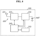
- FIG. 4 is a schematic diagram showing configuration of the master BMS 200 shown in FIG. 1 .
- the master BMS 200 may include a master memory 210, a master communication unit 220, a master power supply unit 230 and a master control unit 240.
- the master memory 210 may store an ID table.
- the ID table includes each ID allocated to the plurality of slave BMSs.
- the master memory 210 is not limited to a particular type and includes any known information storage means capable of recording, deleting, updating and reading data.
- the master memory 210 may be DRAM, SDRAM, flash memory, ROM, EEPROM and a register.
- the master memory 210 may store program codes defining the processes that can be executed by the master control unit 240.
- the master memory 210 may be physically separated from the master control unit 240, and may be integrated into a chip with the master control unit 240.
- the master communication unit 220 includes a master antenna 221 and a master communication circuit 222.
- the master antenna 221 and the master communication circuit 222 are operably connected to each other.
- the master communication circuit 222 may demodulate the wireless signal received through the master antenna 221. Additionally, the master communication circuit 222 may modulate a signal to transmit to each slave BMS 100, and transmit the modulated signal wirelessly through the master antenna 221.
- the master antenna 221 may selectively transmit the wireless signal corresponding to the signal modulated by the master communication unit 220 to at least one of the plurality of slave BMSs 100-1 ⁇ 100-3.
- the master power supply unit 230 generates at least one power source voltage using electrical energy supplied from at least one battery module 20, an external power source or its own power source.
- the power source voltage generated by the master power supply unit 230 may be supplied to the master memory 210 and the master communication unit 220. Additionally, the power source voltage generated by the master power supply unit 230 may be supplied to each processor included in the master control unit 240.
- the master control unit 240 includes at least one processor, and is operably connected to the master memory 210 and the master communication unit 220.
- the master control unit 240 is configured to manage the overall operation of the master BMS 200. Additionally, the master control unit 240 may calculate the State Of Charge (SOC) and/or State Of Health (SOH) of each of the plurality of battery modules 20-1 ⁇ 20-3 based on the wireless signals corresponding to sensing information from each of the plurality of slave BMSs 100-1 ⁇ 100-3 among the wireless signals received through the master antenna 221.
- SOC State Of Charge
- SOH State Of Health
- the master control unit 240 may generate information for controlling the charging, discharging and/or balancing of each of the plurality of slave BMSs 100 based on the calculated SOC and/or SOH, and selectively transmit it to at least one of the plurality of slave BMSs 100-1 ⁇ 100-3 through the master antenna 221 and the master communication unit 220.
- Each processor included in the master control unit 240 may selectively include a processor, an application-specific integrated circuit (ASIC), a chipset, a logic circuit, a register, a communication modem and a data processing device known in the art to execute various control logics. At least one of the various control logics of the master control unit 240 may be combined, and the combined control logics may be written in computer-readable code system and recorded in computer-readable recording media.
- the recording media is not limited to a particular type and includes any type that can be accessed by a processor included in a computer.
- the recording media includes at least one selected from the group consisting of ROM, RAM, a register, CD-ROM, a magnetic tape, a hard disk, a floppy disk and an optical data recording device.
- code system may be modulated to a carrier signal and included in a communication carrier at a particular time point and may be stored and executed in computers connected via a network in distributed manner. Additionally, functional programs, codes and code segments for implementing the combined control logics may be readily inferred by programmers in the technical field to which the present disclosure belongs.
- the master BMS 200 transmits a wireless signal (hereinafter referred to as a 'first RF signal') including a state detection command to the plurality of slave BMSs 100-1 ⁇ 100-3.
- a wireless signal hereinafter referred to as a 'first RF signal'
- each slave BMS 100 detects state information of the battery module 20 to which the slave BMS 100 is coupled.
- the state information of the battery module 20 represents the voltage, current and/or temperature of the battery module 20.
- the state information of the battery module 20 may further include state information of each battery cell 21 included in the battery module 20.
- the state information of the battery cell 21 represents the voltage, current and/or temperature of each of the battery cell 21.
- Each slave BMS 100 is configured to transmit a wireless signal (hereinafter referred to as a 'second RF signal') indicating the state information of the battery module 20 to the master BMS 200.
- a wireless signal hereinafter referred to as a 'second RF signal'
- the master BMS 200 receives the second RF signal from each of the plurality of slave BMSs 100-1 ⁇ 100-3 through the master antenna 221.
- the master BMS 200 calculates the module residual capacity of each of the plurality of battery modules 20-1 ⁇ 20-3 based on the second RF signal received from each of the plurality of slave BMSs 100-1 ⁇ 100-3.
- the module residual capacity represents the State Of Charge (SOC) of the battery module 20.
- the master BMS 200 may further calculate the cell residual capacity of each battery cell 21 included in each of the plurality of battery modules 20-1 ⁇ 20-3 based on the second RF signal received from each of the plurality of slave BMSs 100-1 ⁇ 100-3.
- the cell residual capacity represents the SOC of the battery cell 21.
- the master BMS 200 determines the wireless balancing time for each of the plurality of battery modules 20-1 ⁇ 20-3 according to one of a first balancing rule and a second balancing rule.
- the first balancing rule may be for determining the wireless balancing time for each of the plurality of battery modules 20-1 ⁇ 20-3 based on the module residual capacity of each of the plurality of battery modules 20-1 ⁇ 20-3.
- the second balancing rule may be for determining the wireless balancing time for each of the plurality of battery modules 20-1 ⁇ 20-3 based on the cell residual capacity of each battery cell 21 included in each of the plurality of battery modules 20-1 ⁇ 20-3.
- the master BMS 200 may store the wireless balancing time determined for each of the plurality of slave BMSs 100-1 ⁇ 100-3 in the master memory 210. Along with this or aside from this, the master BMS 200 generates a module balancing command indicating the wireless balancing time determined for each of the plurality of slave BMSs 100-1 ⁇ 100-3. Subsequently, the master BMS 200 may transmit a wireless signal (hereinafter referred to as a 'third RF signal') includng the module balancing command to the plurality of slave BMSs 100-1 ⁇ 100-3.
- a wireless signal hereinafter referred to as a 'third RF signal'
- Each of the plurality of slave BMSs 100-1 ⁇ 100-3 receives the third RF signal through the slave antenna 121.
- Each of the plurality of slave BMSs 100-1 ⁇ 100-3 stores its wireless balancing time determined by the master BMS 200 in the slave memory 110 according to the module balancing command included in the received third RF signal.
- each of the plurality of slave BMSs 100-1 ⁇ 100-3 transmits a wireless signal (hereinafter referred to as a 'fourth RF signal') during its wireless balancing time determined by the master BMS 200 using electrical energy of the battery module 20 to which the slave BMS 100-1 ⁇ 100-3 is coupled.
- the fourth RF signal may be transmitted with the maximum power that is preset for the slave antenna 121.
- Each of the first to third RF signals is a wireless signal transmitted and received through a first wireless channel.
- the fourth RF signal is a wireless signal transmitted by each slave BMS 100 through a second wireless channel.
- the first wireless channel is a communication channel, and has a preset first frequency range.
- the second wireless channel is a non-communication channel, and has a preset second frequency range that is separated from the first frequency range.
- the slave communication units 120 of each slave BMS 100 are designed to selectively access the first and second wireless channels.
- the mast communication unit 220 of the master BMS 200 may be designed to access only the first wireless channel among the first and second wireless channels. Accordingly, the fourth RF signal may not affect the operation of the master BMS 200.
- electrical energy consumed from each battery module 20 by the operation other than module balancing and cell balancing is so small to be negligible, compared to electrical energy consumed from each battery module 20 by module balancing and cell balancing.
- FIGS. 5 and 6 are diagrams for reference in describing the operation of balancing the plurality of battery modules according to the first balancing rule by the wireless battery management system 30 according to an embodiment of the present disclosure.
- FIG. 5 shows one examplary state before determining the wireless balancing time for each of the plurality of battery modules 20-1 ⁇ 20-3.
- the cell residual capacities of three battery cells 21-1 ⁇ 21-3 included in the first battery module 20-1 are 3.0kAh, 3.1kAh and 3.0kAh respectively
- the cell residual capacities of three battery cells 21-4 ⁇ 21-6 included in the second battery module 20-2 are 3.3kAh, 3.1kAh and 3.0kAh respectively
- the cell residual capacities of three battery cells 21-7 ⁇ 21-9 included in the third battery module 20-3 are 3.2kAh, 3.2kAh and 3.3kAh respectively.
- the module residual capacity of the first battery module 20-1 is 9.1kAh
- the module residual capacity of the second battery module 20-2 is 9.4kAh
- the module residual capacity of the third battery module 20-3 is 9.7kAh.
- kAh is an abbreviation of kilo ampere hour, and is a unit that indicates the residual capacity.
- the master BMS 200 sets the module residual capacity of one of the plurality of battery modules 20-1 ⁇ 20-3 as first target residual capacity.
- the smallest module residual capacity 9.1KAh among the module residual capacities 9.1kAh, 9.4kAh and 9.7kAh of the plurality of battery modules 20-1 ⁇ 20-3 may be set as the first target residual capacity.
- the master BMS 200 determines the wireless balancing time for each of the plurality of battery modules 20-1 ⁇ 20-3 based on the differences between the first target residual capacity 9.1kAh and each of the other module residual capacities 9.4kAh, 9.7kAh. Specifically, the master BMS 200 determines the wireless balancing time for the second battery module 20-2 based on the difference 0.3kAh between the first target residual capacity 9.1kAh and the module residual capacity 9.4kAh of the second battery module 20-2. Additionally, the master BMS 200 determines the wireless balancing time for the third battery module 20-3 based on the difference 0.6KAh between the first target residual capacity 9.1kAh and the module residual capacity 9.7kAh of the third battery module 20-3.
- the wireless balancing time determined for each battery module 20 may increase.
- the wireless balancing time ('D3' in FIG. 6 ) determined for the third battery module 20-3 is longer than the wireless balancing time ('D2' in FIG. 6 ) determined for the second battery module 20-2.
- the master BMS 200 may determine the wireless balancing time for the first battery module 20-1 having the same module residual capacity as the first target residual capacity 9.1kAh to be equal to the reference time (for example, 0 sec).
- FIG. 6 is a timing chart illustrating the operation for balancing the plurality of battery modules 20-1 ⁇ 20-3 shown in FIG. 5 by the wireless battery management system 30.
- the master BMS 200 transmits the first RF signal 601 to the plurality of slave BMSs 100-1 ⁇ 100-3 through the first wireless channel.
- a difference between the smallest and second smallest of the module residual capacities of the plurality of battery modules 20-1 ⁇ 20-3 may be less than first threshold.
- module balancing may be stopped.
- each of the plurality of slave BMSs 100-1 ⁇ 100-3 detects state information of each of the battery modules 20-1 ⁇ 20-3 to which the slave BMS 100-1 ⁇ 100-3 is coupled.
- each of the plurality of slave BMSs 100-1 ⁇ 100-3 transmits the second RF signal 611, 621, 631 indicating the state information (see FIG. 5 ) detected from the battery modules 20-1 ⁇ 20-3 to which each of the slave BMS 100-1 ⁇ 100-3 is coupled to the master BMS 200 through the first wireless channel.
- the master BMS 200 determines the wireless balancing time for each of the plurality of battery modules 20-1 ⁇ 20-3 based on the second RF signal 611, 621, 631.
- the master BMS 200 transmits the first RF signal 602 and the third RF signal 603 to the plurality of slave BMSs 100-1 ⁇ 100-3 through the first wireless channel.
- the third RF signal 603 includes a module balancing command indicating the wireless balancing time determined for each of the plurality of battery modules 20-1 ⁇ 20-3.
- the wireless balancing time for the first battery module 20-1 may be 0 sec. Accordingly, the first slave BMS 100-1 does not perform module balancing of the first battery module 20-1. Between time points T6 and T7, in response to the first RF signal 602, the first slave BMS 100-1 detects state information of the first battery module 20-1. In this case, until the time point T7, the module residual capacity of the first battery module 20-1 may be maintained at 9.1 kAh. Subsequently, between time points T7 and T9, the first slave BMS 100-1 may transmit the second RF signal 612 indicating the state information of the first battery module 20-1 to the master BMS 200 through the first wireless channel.
- the second slave BMS 100-2 transmits the fourth RF signal 622 through the second wireless channel using electrical energy of the second battery module 20-2 during the wireless balancing time D2 according to the module balancing command included in the third RF signal 603. Accordingly, after transmission of the fourth RF signal 622 than before, the module residual capacity of the second battery module 20-2 is closer to the first target residual capacity 9.1 kAh.
- the cell residual capacities of the three battery cells 21-4 ⁇ 21-6 are reduced by 0.1kAh and reach 3.2kAh, 3.0kAh and 2.9kAh respectively, and thus the module residual capacity of the second battery module 20-2 at the time point T8 may be equal to the first target residual capacity 9.1kAh.
- the second slave BMS 100-2 may detect state information of the second battery module 20-2. From the time point T6 to the time point T8, cell balancing of the battery cells 21-4 ⁇ 21-6 included in the second battery module 20-2 may not be performed. That is, from the time point T6 to the time point T8, all the balancing switches SW of the wired balancing unit 140 of the second slave BMS 100-2 may be turned off. Accordingly, the slave sensing unit 130 of the second slave BMS 100-2 may detect state information of the second battery module 20-2.
- the second slave BMS 100-2 transmits the second RF signal 623 indicating the state information of the second battery module 20-2 to the master BMS 200 through the first wireless channel.
- the third slave BMS 100-3 transmits the fourth RF signal 632 through the second wireless channel using electrical energy of the third battery module 20-3 for the wireless balancing time D3 according to the module balancing command included in the third RF signal 603. Accordingly, after transmission of the fourth RF signal 632 than before, the module residual capacity of the third battery module 20-3 is closer to the first target residual capacity 9.1kAh.
- the cell residual capacities of the three battery cells 21-7 ⁇ 21-9 are reduced by 0.2kAh when compared to FIG. 5 and reach 3.0kAh, 3.0kAh and 3.1kAh respectively, and thus the module residual capacity of the third battery module 20-3 at the time point T11 may be equal to the first target residual capacity 9.1kAh.
- the third slave BMS 100-3 may detect state information of the third battery module 20-3. From the time point T6 to the time point T11, cell balancing of the battery cells 21-7 ⁇ 21-9 included in the third battery module 20-3 may not be performed. That is, from the time point T6 to the time point T11, all the balancing switches SW of the wired balancing unit 140 of the third slave BMS 100-3 may be turned off. Accordingly, the slave sensing unit 130 of the third slave BMS 100-3 may detect state information of the third battery module 20-3.
- the third slave BMS 100-3 may transmit the second RF signal 633 indicating the state information of the third battery module 20-3 to the master BMS 200 through the first wireless channel.
- the module balancing command of the third RF signal 603 is for reducing a difference in module residual capacities of the plurality of battery modules 20-1 ⁇ 20-3, but not a difference in cell residual capacities of the plurality of battery cells 21 included in the common battery module 20. It is because, as shown in FIG. 5 , when one of the plurality of battery cells 20 connected in series within the same battery module 20 is discharged, each of the other battery cells is discharged as much during module balancing.
- the wired balancing time for at least one battery cell 21 included in the plurality of battery modules 20-1 ⁇ 20-3 may be further determined.
- the wired balancing time determined for each battery cell 21 may be based on a difference between the cell residual capacity of each battery cell 21 and the minimum cell residual capacity of the battery module 20 including each battery cell 21.
- the wired balancing time for the battery cell 21-2 may be determined based on a difference 0.1kAh between the cell residual capacity 3.1kAh of the battery cell 21-2 and the minimum cell residual capacity 3.0kAh of the first battery module 20-1 including the battery cell 21-2.
- the wired balancing time for the battery cell 21-4 may be determined based on a difference 0.3kAh between the cell residual capacity 3.3kAh of the battery cell 21-4 and the minimum cell residual capacity 3.0kAh of the second battery module 20-2 including the battery cell 21-4.
- the master BMS 200 may further include a cell balancing command in the third RF signal 603.
- the cell balancing command may represent the wired balancing time for at least one battery cell 21 included in the plurality of battery modules 20-1 ⁇ 20-3.
- the first slave BMS 100-1 may perform selective cell balancing of the three battery cells 21-1 ⁇ 21-3 by controlling the wired balancing unit 140 included in the first slave BMS 100-1 according to the cell balancing command of the third RF signal 603. After the time point T9, the first slave BMS 100-1 may discharge at least one of the three battery cells 21-1 ⁇ 21-3 by controlling the balancing switch SW of the wired balancing unit 140. T13 may be the time point at which the master BMS 200 transmits a new third RF signal through the first wireless channel.
- the first slave BMS 100-1 may turn on the balancing switch SW connected between two ends of the battery cell 21-2, and turn off the balancing switch SW connected between two ends of each of the other battery cells 21-1, 21-3 to reduce the cell residual capacity of the battery cell 21-2 by 0.1kAh.
- the balancing switch SW connected between two ends of the battery cell 21-2 may be turned on for the wired balancing time determined for the battery cell 21-2. Accordingly, at an arbitrary time point after the time point T9, the cell residual capacities of the three battery cells 21-1 ⁇ 21-3 may be all equalized and reach 3.0kAh respectively. That is, the module residual capacity of the first battery module 20-1 may be 9.0kAh.
- the second slave BMS 100-2 may perform selective cell balancing of the three battery cells 21-4 ⁇ 21-6 by controlling the wired balancing unit 140 according to the cell balancing command of the third RF signal 603. For at least some time between the time points T10 and T13, the second slave BMS 100-2 may discharge at least one of the three battery cells 21-4 ⁇ 21-6 by controlling the balancing switch SW of the wired balancing unit 140.
- the second slave BMS 100-2 may turn on the balancing switch SW connected between two ends of the battery cell 21-4 to reduce the cell residual capacity of the battery cell 21-4 by 0.3kAh, turn on the balancing switch SW connected between two ends of the battery cell 21-5 to reduce the cell residual capacity of the battery cell 21-5 by 0.1kAh, and turn off the balancing switch SW connected between two ends of the remaining battery cell 21-6.
- the balancing switch SW connected between two ends of the battery cell 21-4 may be turned on for the wired balancing time determined for the battery cell 21-4.
- the balancing switch SW connected between two ends of the battery cell 21-5 may be turned on for the wired balancing time determined for the battery cell 21-5.
- the cell residual capacities of the three battery cells 21-4 ⁇ 21-6 may be all equalized and reach 2.9kAh respectively. That is, the module residual capacity of the second battery module 20-2 may be 8.7kAh.
- the third slave BMS 100-3 may perform selective cell balancing of the three battery cells 21-7 ⁇ 21-9 by controlling the wired balancing unit 140 according to the cell balancing command of the third RF signal 603. For at least some time between the time points T12 and T13, the third slave BMS 100-3 may discharge at least one of the three battery cells 21-7 ⁇ 21-9 by controlling the balancing switch SW of the wired balancing unit 140.
- the third slave BMS 100-3 may turn off the balancing switch SW connected between two ends of the battery cell 21-8, turn on the balancing switch SW connected between two ends of the battery cell 21-9 to reduce the cell residual capacity of the battery cell 21-9 by 0.1kAh, and turn off the balancing switch SW connected between two ends of the remaining battery cell 21-7.
- the balancing switch SW connected between two ends of the battery cell 21-9 may be turned on for the wired balancing time determined for the battery cell 21-9. Accordingly, at an arbitrary time point after the time point T12, the cell residual capacities of the three battery cells 21-7 ⁇ 21-9 may be all equalized and reach 3.0kAh respectively. That is, the module residual capacity of the third battery module 20-3 may be 9.0kAh.
- the first and third slave BMSs 100-1, 100-3 may reduce the module residual capacities of each of the first and third battery modules 20-1, 20-3 by 0.3kAh according to the module balancing command included in a new third RF signal from the master BMS 200. Accordingly, the module residual capacities of the first to third battery modules 20-1 ⁇ 20-3 are all equalized and reach 8.7kAh.
- FIGS. 7 and 8 are diagrams for reference in describing the operation of balancing the plurality of battery modules according to the second balancing rule by the wireless battery management system 30 according to an embodiment of the present disclosure.
- FIG. 7 shows other examplary state before determining the wireless balancing time for each of the plurality of battery modules 20-1 ⁇ 20-3.
- the cell residual capacities of the three battery cells 21-1 ⁇ 21-3 included in the first battery module 20-1 are 3.0kAh, 3.1kAh, 3.0kAh respectively
- the cell residual capacities of the three battery cells 21-4 ⁇ 21-6 included in the second battery module 20-2 are 3.2kAh, 3.0kAh, 2.9kAh respectively
- the cell residual capacities of the three battery cells 21-7 ⁇ 21-9 included in the third battery module 20-3 are 3.1kAh, 3.2kAh, 3.1kAh respectively.
- the module residual capacity of the first battery module 20-1 is 9.1kAh
- the module residual capacity of the second battery module 20-2 is 9.1kAh
- the module residual capacity of the third battery module 20-3 is 9.4kAh.
- the master BMS 200 sets one of all the battery cells 21-1 ⁇ 21-9 included in the plurality of battery modules 20-1 ⁇ 20-3 as second target residual capacity.
- a smallest one of all the battery cells 21-1 ⁇ 21-9 included in the plurality of battery modules 20-1 ⁇ 20-3 is determined as the second target residual capacity.
- the cell residual capacity 2.9kAh of the battery cell 21-6 is set as the second target residual capacity.
- the master BMS 200 determines the minimum cell residual capacity of each of the plurality of battery modules 20-1 ⁇ 20-3.
- the minimum cell residual capacity of the first battery module 20-1 is determined as the cell residual capacity 3.0kAh of the battery cell 21-1 or the battery cell 21-3
- the minimum cell residual capacity of the second battery module 20-2 is determined as the cell residual capacity 2.9kAh of the battery cell 21-6
- the minimum cell residual capacity of the third battery module 20-3 is determined as the cell residual capacity 3.1kAh of the battery cell 21-7 or the battery cell 21-9.
- the master BMS 200 may determine the wireless balancing time for each of the plurality of battery modules 20-1 ⁇ 20-3 based on the differences between the second target residual capacity and the minimum cell residual capacities of each of the other battery modules 20.
- the master BMS 200 determines the wireless balancing time for the first battery module 20-1 based on the difference 0.1kAh between the second target residual capacity 2.9kAh and the minimum cell residual capacity 3.0kAh of the first battery module 20-1.
- the master BMS 200 determines the wireless balancing time for the third battery module 20-3 based on the difference 0.2kAh between the second target residual capacity 2.9kAh and the minimum cell residual capacity 3.1kAh of the third battery module 20-3.
- the wireless balancing time determined for each battery module 20 may increase.
- the wireless balancing time for the first battery module 20-1 may correspond to 0.3kAh that is obtained by multiplying the difference 0.1kAh by the number (3) of battery cells 21 included in the first battery module 20-1
- the wireless balancing time for the third battery module 20-3 may correspond to 0.6kAh that is obtained by multiplying the difference 0.2kAh by the number (3) of battery cells 21 included in the third battery module 20-3.
- the wireless balancing time ('D13' in FIG. 8 ) for the third battery module 20-3 is longer than the wireless balancing time ('D11' in FIG. 8 ) for the first battery module 20-1.
- the second target residual capacity 2.9kAh is equal to the minimum cell residual capacity 2.9kAh of the second battery module 20-1.
- the master BMS 200 may determine the wireless balancing time for the second battery module 20-1 to be equal to the reference time (for example, 0 sec).
- FIG. 8 is a timing chart illustrating the operation of balancing the plurality of battery modules 20-1 ⁇ 20-3 shown in FIG. 7 by the wireless battery management system 30.
- the master BMS 200 transmits the first RF signal 701 to the plurality of slave BMSs 100-1 ⁇ 100-3 through the first wireless channel.
- a difference between the smallest and second smallest of the minimum cell residual capacities of the plurality of battery modules 20-1 ⁇ 20-3 may be less than second threshold.
- module balancing may be stopped.
- each of the plurality of slave BMSs 100-1 ⁇ 100-3 detects state information of the battery module 20 to which the slave BMS 100-1 ⁇ 100-3 is coupled.
- each of the plurality of slave BMSs 100-1 ⁇ 100-3 transmits the second RF signal 711, 721, 731 indicating the state information (see FIG. 7 ) detected from the battery module 20-1, 20-3, 20-3 in which the slave BMS 100-1-100-3 is installed to the master BMS 200 through the first wireless channel.
- the master BMS 200 determines the wireless balancing time for each of the plurality of battery modules 20-1 ⁇ 20-3 based on the second RF signal 711, 721, 731.
- the master BMS 200 transmits the first RF signal 702 and the third RF signal 703 to the plurality of slave BMSs 100-1 ⁇ 100-3 through the first wireless channel.
- the third RF signal 703 includes a module balancing command indicating the wireless balancing time determined for each of the plurality of battery modules 20-1 ⁇ 20-3.
- the first slave BMS 100-1 transmits the fourth RF signal 712 through the second wireless channel for the wireless balancing time D11 using electrical energy of the first battery module 20-1 according to the module balancing command included in the third RF signal 703. Accordingly, after transmission of the fourth RF signal 712 than before, the minimum cell residual capacity of the first battery module 20-1 is closer to the second target residual capacity 2.9kAh.
- the cell residual capacities of the three battery cells 21-1 ⁇ 21-3 are reduced by 0.1kAh and reach 2.9kAh, 3.0kAh and 2.9kAh respectively, and thus the minimum cell residual capacity of the first battery module 20-1 at the time point T28 may be equal to the second target residual capacity 2.9kAh.
- the first slave BMS 100-1 may detect state information of the first battery module 20-1. From the time point T26 to the time point T28, cell balancing of the battery cells 21-1 ⁇ 21-3 included in the first battery module 20-1 may not be performed. That is, from time points T26 to T28, all the balancing switches SW of the wired balancing unit 140 of the first slave BMS 100-1 may be turned off. Accordingly, the slave sensing unit 130 of the first slave BMS 100-1 may detect state information of the first battery module 20-1.
- the first slave BMS 100-1 transmits the second RF signal 713 indicating the state information of the first battery module 20-1 to the master BMS 200 through the first wireless channel.
- the wireless balancing time for the second battery module 20-2 may be 0 sec. Accordingly, the second slave BMS 100-2 does not perform module balancing of the second battery module 20-2. Between time points T26 and T27, in response to the first RF signal 702, the second slave BMS 100-2 detects state information of the second battery module 20-2. In this case, until the time point T27, the module residual capacity of the second battery module 20-2 may be maintained at 9.1kAh. Between time points T27 and T29, the second slave BMS 100-2 transmits the second RF signal 722 indicating the state information of the second battery module 20-2 to the master BMS 200 through the first wireless channel.
- the third slave BMS 100-3 transmits the fourth RF signal 732 through the second wireless channel for the wireless balancing time D13 using electrical energy of the third battery module 20-3 according to the module balancing command included in the third RF signal 703. Accordingly, after transmission of the fourth RF signal 732 than before, the minimum cell residual capacity of the third battery module 20-3 is closer to the second target residual capacity 2.9kAh.
- the cell residual capacities of the three battery cells 21-7 ⁇ 21-9 are reduced by 0.2kAh when compared to FIG. 7 and reach 2.9kAh, 3.0kAh and 2.9kAh respectively, and thus the minimum cell residual capacity of the third battery module 20-3 at T31 may be equal to the second target residual capacity 2.9kAh.
- the third slave BMS 100-3 may detect state information of the third battery module 20-3. From the time point T26 to the time point T31, cell balancing of the battery cells 21-7 ⁇ 21-9 included in the third battery module 20-3 may not be performed. That is, from the time point T26 to the time point T31, all the balancing switches SW of the wired balancing unit 140 of the third slave BMS 100-3 may be turned off. Accordingly, the slave sensing unit 130 of the third slave BMS 100-3 may detect state information of the third battery module 20-3.
- the third slave BMS 100-3 may transmit the second RF signal 733 indicating the state information of the third battery module 20-3 to the master BMS 200 through the first wireless channel.
- the module balancing command of the third RF signal 703 is for equalizing the minimum cell residual capacities of the plurality of battery modules 20-1 ⁇ 20-3, but not reducing a difference in cell residual capacities of the plurality of battery cells 21 included in the common battery module 20. It is because, as shown in FIG. 7 , when one of the plurality of battery cells 20 connected in series within the same battery module 20 is discharged, each of the other battery cells is discharged as much during module balancing.
- the master BMS 200 may further include a cell balancing command in the third RF signal 703.
- the first slave BMS 100-1 may perform selective cell balancing of the three battery cells 21-1 ⁇ 21-3 by controlling the wired balancing unit 140 according to the cell balancing command of the third RF signal 703. For at least some time between the time points T30 and T33, the first slave BMS 100-1 may discharge at least one of the three battery cells 21-1 ⁇ 21-3 by controlling the balancing switch SW of the wired balancing unit 140.
- the time point T33 may be the time point at which the master BMS 200 transmits a new third RF signal through the first wireless channel.
- the first slave BMS 100-1 may turn on the balancing switch SW connected between two ends of the battery cell 21-2 and turn off the balancing switch SW connected between two ends of each of the other battery cells 21-1, 21-3 to reduce the cell residual capacity of the battery cell 21-2 by 0.1kAh.
- the balancing switch SW connected between two ends of the battery cell 21-2 may be turned on for the wired balancing time determined for the battery cell 21-2. Accordingly, at an arbitrary time point after the time point T30, the cell residual capacities of the three battery cells 21-1 ⁇ 21-3 may be all equalized and reach 2.9kAh. That is, the module residual capacity of the first battery module 20-1 may be 8.7kAh.
- the second slave BMS 100-2 may perform selective cell balancing of the three battery cells 21-4 ⁇ 21-6 by controlling the wired balancing unit 140 according to the cell balancing command of the third RF signal 703. For at least some time between time points T29 and T33, the second slave BMS 100-2 may discharge at least one of the three battery cells 21-4 ⁇ 21-6 by controlling the balancing switch SW of the wired balancing unit 140.
- the second slave BMS 100-2 may turn on the balancing switch SW connected between two ends of the battery cell 21-4 to reduce the cell residual capacity of the battery cell 21-4 by 0.3kAh, turn on the balancing switch SW connected between two ends of the battery cell 21-5 to reduce the cell residual capacity of the battery cell 21-5 by 0.1kAh, and turn off the balancing switch SW connected between two ends of the remaining battery cell 21-6.
- the balancing switch SW connected between two ends of the battery cell 21-4 may be turned on for the wired balancing time determined for the battery cell 21-4.
- the balancing switch SW connected between two ends of the battery cell 21-5 may be turned on for the wired balancing time determined for the battery cell 21-5. Accordingly, at an arbitrary time point after T29, the cell residual capacities of the three battery cells 21-4 ⁇ 21-6 may be all equalized and reach 2.9kAh. That is, the module residual capacity of the second battery module 20-2 may be 8.7kAh.
- the third slave BMS 100-3 may perform selective cell balancing of the three battery cells 21-7 ⁇ 21-9 by controlling the wired balancing unit 140 according to the cell balancing command of the third RF signal 703. For at least some time between time points T32 and T33, the third slave BMS 100-3 may discharge at least one of the three battery cells 21-7 ⁇ 21-9 by controlling the balancing switch SW of the wired balancing unit 140.
- the third slave BMS 100-3 may turn on the balancing switch SW connected between two ends of the battery cell 21-8 to reduce the cell residual capacity of the battery cell 21-8 by 0.1kAh, and turn off the balancing switch SW connected between two ends of each of the remaining battery cells 21-7, 21-9.
- the balancing switch SW connected between two ends of the battery cell 21-8 may be turned on for the wired balancing time determined for the battery cell 21-8. Accordingly, at an arbitrary time point after the time point T32, the cell residual capacities of the three battery cells 21-7 ⁇ 21-9 may be all equalized and reach 2.9kAh. That is, the module residual capacity of the third battery module 20-3 may be 8.7kAh.
- the wireless battery management system 30 may perform the cell balancing operation first and then perform module balancing.
- the residual capacities of all the battery cells 21-1 ⁇ 21-3 of the first battery module 20-1 are 3.0kAh
- the residual capacities of all the battery cells 21-4 ⁇ 21-6 of the second battery module 20-2 are 2.9kAh
- the residual capacities of all the battery cells 21-7 ⁇ 21-9 of the third battery module 20-3 are 3.1kAh. It is because the cell balancing operation is performed by balancing all the other battery cells 21 based on the minimum cell residual capacity of each battery module 20.
- the residual capacities of all the battery cells 21-1 ⁇ 21-3 of the first battery module 20-1 are reduced by 0.1kAh respectively, and the residual capacities of all the battery cells 21-7 ⁇ 21-9 of the third battery module 20-3 are reduced by 0.2kAh respectively. Accordingly, it is possible to remove not only a difference in module residual capacity between all the battery modules 20-1 ⁇ 20-3 but also a difference in cell residual capacity between all the battery cells 21-1 ⁇ 21-9.
Landscapes
- Engineering & Computer Science (AREA)
- Power Engineering (AREA)
- Sustainable Development (AREA)
- Mechanical Engineering (AREA)
- Transportation (AREA)
- Sustainable Energy (AREA)
- Life Sciences & Earth Sciences (AREA)
- Electrochemistry (AREA)
- General Chemical & Material Sciences (AREA)
- Chemical Kinetics & Catalysis (AREA)
- Chemical & Material Sciences (AREA)
- Manufacturing & Machinery (AREA)
- Physics & Mathematics (AREA)
- General Physics & Mathematics (AREA)
- Computer Networks & Wireless Communication (AREA)
- Signal Processing (AREA)
- Charge And Discharge Circuits For Batteries Or The Like (AREA)
- Remote Monitoring And Control Of Power-Distribution Networks (AREA)
- Secondary Cells (AREA)
Abstract
Description
- The present disclosure relates to a wireless battery management system, and more particularly, to a wireless battery management system for reducing a residual capacity deviation between battery modules and a battery pack including the same.
- The present application claims priority to Korean Patent Application No.
10-2017-0092151 - Recently, there is dramatically growing demand for portable electronic products such as laptop computers, video cameras and mobile phones, and with the extensive development of electric vehicles, accumulators for energy storage, robots and satellites, many studies are being made on high performance secondary batteries that can be recharged repeatedly.
- Currently, commercially available secondary batteries include nickel-cadmium batteries, nickel-hydrogen batteries, nickel-zinc batteries, lithium secondary batteries and the like, and among them, lithium secondary batteries have little or no memory effect, and thus they are gaining more attention than nickel-based secondary batteries for their advantages of free charging and discharging, very low self-discharging and high energy density.
- A battery pack applied to electric vehicles generally includes a plurality of battery modules connected in series and a plurality of battery management systems (BMSs). Each BMS monitors and controls the state of the battery module that the BMU manages. Recently, to meet the demand for high-capacity high-output battery packs, the number of battery modules included in a battery pack also increases. To efficiently manage the state of each battery module included in the battery pack, a single master-multi slave structure is disclosed. The single master-multi slave structure includes a plurality of slave BMSs installed in each battery module and a master BMS that controls the overall operation of the plurality of slave BMSs. In this instance, communication between the plurality of slave BMSs and the master BMS may be performed by a wireless method.
- Each of the plurality of slave BMSs transmits a wireless signal to the master BMS or receives a wireless signal from the master BMS using electrical energy of the battery module in which the slave BMS is coupled.
- Meanwhile, due to the environment in which the battery pack operates or the electrical and chemical properties of the individual battery module, a residual capacity deviation often occurs between the plurality of battery modules. To reduce the residual capacity deviation between the plurality of battery modules, balancing control is necessary.
- However, most of conventional technologies related to balancing have applications in systems designed for communication between a plurality of slave BMSs and a master BMS through wired means such as a cable.
- The present disclosure is directed to providing a wireless battery management system for performing module balancing to reduce a residual capacity deviation between battery modules by transmitting a radio frequency (RF) signal through a non-communication wireless channel using electrical energy of at least one of the battery modules, and a battery pack including the same.
- These and other objects and advantages of the present disclosure will be understood by the following description and will be apparent from the embodiments of the present disclosure. Further, it will be readily understood that the objects and advantages of the present disclosure can be realized by the means set forth in the appended claims and combinations thereof.
- Various embodiments of the present disclosure for achieving the above-described object are as follows.
- A wireless battery management system according to an aspect of the present disclosure includes a master BMS configured to transmit a first radio frequency (RF) signal including a state detection command through a first wireless channel. The wireless battery management system further includes a plurality of slave BMSs coupled to a plurality of battery modules in one-to-one correspondence. Each of the plurality of slave BMSs is configured to detect state information of the battery module to which the corresponding slave BMS is coupled in response to the first RF signal, and transmit a second RF signal indicating the state information of the battery module through the first wireless channel. The master BMS is configured to determine a wireless balancing time for each of the plurality of battery modules based on the second RF signal, and transmit a third RF signal including a module balancing command indicating the wireless balancing time to the plurality of slave BMSs through the first wireless channel. Each of the plurality of slave BMSs is configured to transmit a fourth RF signal through a second wireless channel during the wireless balancing time using electrical energy of the battery module to which the corresponding slave BMS is coupled according to the module balancing command included in the third RF signal.
- The first wireless channel may have a preset first frequency range. In this case, the second wireless channel may have a preset second frequency range that is separated from the first frequency range.
- The master BMS may calculate a module residual capacity stored in each of the plurality of battery modules based on the second RF signal, and determine the wireless balancing time for each of the plurality of battery modules based on the module residual capacity of each of the plurality of battery modules.
- The master BMS may set the module residual capacity of one of the plurality of battery modules as a first target residual capacity, and determine the wireless balancing time for each of the plurality of battery modules based on a difference between the first target residual capacity and each of the other module residual capacities.
- The state information of the battery module may include state information of each battery cell included in the battery module. The master BMS may calculate a cell residual capacity of each battery cell included in each of the plurality of battery modules based on the second RF signal, and determine the wireless balancing time for each of the plurality of battery modules based on the cell residual capacity of each battery cell included in each of the plurality of battery modules.
- The master BMS may determine a smallest cell residual capacity of cell residual capacities of all battery cells included in the plurality of battery modules as second target residual capacity, and determine the wireless balancing time for each of the plurality of battery modules further based on a difference between the second target residual capacity and the minimum cell residual capacity of each of the other battery modules.
- The master BMS may determine a wired balancing time for each battery cell included in each of the plurality of battery modules based on a difference between the minimum cell residual capacity of each of the plurality of battery modules and each of the other cell residual capacities. In this case, the third RF signal may further include a cell balancing command indicating the wired balancing time.
- Each of the plurality of slave BMSs may include a wired balancing unit electrically connected to two ends of each battery cell included in the battery module to which the corresponding slave BMS is coupled. Each of the plurality of slave BMSs may balance the cell residual capacity of each battery cell included in the battery module to which the corresponding slave BMS is coupled by controlling the wired balancing unit according to the cell balancing command included in the third RF signal.
- A battery pack according to another aspect of the present disclosure includes the wireless battery management system and the plurality of battery modules.
- According to at least one of the embodiments of the present disclosure, it is possible to perform module balancing to reduce a residual capacity deviation between battery modules by transmitting a radio frequency (RF) signal through a non-communication wireless channel using electrical energy of at least one of the battery modules.
- Additionally, according to at least one of the embodiments of the present disclosure, it is possible to performed module balancing even while state information from each battery module is being detectd, thereby reducing the time required to finish module balancing and cell balancing completely.
- Additionally, according to at least one of the embodiments of the present disclosure, module balancing is performed first based on the minimum cell residual capacity of each battery module and then cell balancing is performed, so there is available time for cell balancing.
- The effects of the present disclosure are not limited to the above-mentioned effects, and other effects not mentioned herein will be clearly understood by those skilled in the art from the appended claims.
- The accompanying drawings illustrate a preferred embodiment of the present disclosure, and together with the detailed description of the present disclosure described below, serve to provide a further understanding of the technical aspects of the present disclosure, and thus, the present disclosure should not be construed as being limited to the drawings.
-
FIG. 1 is a schematic diagram showing configuration of a wireless battery management system according to an embodiment of the present disclosure and a battery pack including the same. -
FIG. 2 is a schematic diagram showing configuration of a slave BMS shown inFIG. 1 . -
FIG. 3 is a schematic diagram showing configuration of a wired balancing unit according to an embodiment of the present disclosure. -
FIG. 4 is a schematic diagram showing configuration of a master BMS shown inFIG. 1 . -
FIGS. 5 and6 are diagrams for reference in describing the operation of balancing a plurality of battery modules according to a first balancing rule by a wireless battery management system according to an embodiment of the present disclosure. -
FIGS. 7 and8 are diagrams for reference in describing the operation of balancing a plurality of battery modules according to a second balancing rule by a wireless battery management system according to an embodiment of the present disclosure. - Hereinafter, the preferred embodiments of the present disclosure will be described in detail with reference to the accompanying drawings. Prior to the description, it should be understood that the terms or words used in the specification and the appended claims should not be construed as being limited to general and dictionary meanings, but interpreted based on the meanings and concepts corresponding to the technical aspects of the present disclosure on the basis of the principle that the inventor is allowed to define the terms appropriately for the best explanation.
- Therefore, the embodiments described herein and illustrations shown in the drawings are just a most preferred embodiment of the present disclosure, but not intended to fully describe the technical aspects of the present disclosure, so it should be understood that a variety of other equivalents and modifications could be made thereto at the time of filing the application.
- Additionally, in describing the present disclosure, when it is deemed that a certain detailed description of relevant known elements or functions renders the key subject matter of the present disclosure ambiguous, the detailed description is omitted herein.
- The terms including the ordinal number such as "first", "second" and the like, may be used to distinguish one element from another among various elements, but not intended to limit the elements by the terms.
- Unless the context clearly indicates otherwise, it will be understood that the term "comprises" or "includes" when used in this specification, specifies the presence of stated elements, but does not preclude the presence or addition of one or more other elements. Additionally, the term <control unit> as used herein refers to a processing unit of at least one function or operation, and this may be implemented by hardware or software alone or in combination.
- In addition, throughout the specification, it will be further understood that when an element is referred to as being "connected to" another element, it can be directly connected to the other element or intervening elements may be present.
- It should be noted that the term "BMS" as used herein is a shorted form of Battery Management System.
-
FIG. 1 is a schematic diagram showing configuration of a wirelessbattery management system 30 according to an embodiment of the present disclosure and abattery pack 10 including the same. - Referring to
FIG. 1 , thebattery pack 10 includes a plurality ofbattery modules 20 and a wirelessbattery management system 30. Eachbattery module 20 may include at least one battery cell (see 21 inFIG. 2 ). The wirelessbattery management system 30 includes a plurality ofslave BMSs 100 and at least onemaster BMS 200. Thebattery pack 10 may be mounted in an electric vehicle to supply power required for operating an electric motor of the electric vehicle. - Hereinafter, for convenience of description, assume that the
battery pack 10 includes three battery modules 20-1∼20-3 connected in series, eachbattery module 20 includes threebattery cells 21 connected in series, and the wirelessbattery management system 30 includes three slave BMSs 100-1∼100-3 and asingle master BMS 200. However, the scope of the present disclosure is not limited thereto. For example, thebattery pack 10 may include only twobattery modules 20 or four ormore battery modules 20. Of course, the wirelessbattery management system 30 may include twoslave BMSs 100 or four ormore slave BMSs 100, and may include two ormore master BMSs 200. - The plurality of slave BMSs 100-1∼100-3 is coupled in one-to-one correspondence to the plurality of battery modules 20-1∼20-3 included in the
battery pack 10. - Each of the plurality of slave BMSs 100-1∼100-3 is electrically connected to one of the plurality of battery modules 20-1∼20-3. Each of the plurality of slave BMSs 100-1∼100-3 detects the overall state (for example, voltage, current, temperature) of the battery modules 20-1∼20-3 electrically connected to the slave BMSs 100-1∼100-3, and performs a variety of control functions (for example, charging, discharging, balancing) to adjust the state of the battery modules 20-1∼20-3. Each control function may be performed directly by the
slave BMS 100 based on the state of thebattery module 20, or may be performed according to the command from themaster BMS 200. -
FIG. 2 is a schematic diagram showing configuration of theslave BMS 100 shown inFIG. 1 , andFIG. 3 is a shematic diagram showing configuration of awired balancing unit 140 according to an embodiment of the present disclosure. - Referring to
FIG. 2 , eachslave BMS 100 may include aslave memory 110, aslave communication unit 120, aslave sensing unit 130, a slavepower supply unit 150 and aslave control unit 160. Optionally, eachslave BMS 100 may further include awired balancing unit 140. - The
slave memory 110 stores an ID allocated to theslave BMS 100. The ID may be allocated in the manufacture of theslave BMS 100 including theslave memory 110. The ID may be used for eachslave BMS 100 to perform wireless communication with themaster BMS 200. In this instance, the ID allocated to one of the plurality of slave BMSs 100-1∼100-3 may be different from the IDs allocated to each of the other slave BMSs. - Each ID may be used for the
master BMS 200 to distinguish each slave BMS 100 (e.g. 100-1) from the other slave BMS 100 (e.g. 100-2). Additionally, each ID may represent which of the plurality of battery modules 20-1∼20-3 at which theslave BMS 100 with the allocated ID is installed. - The
slave memory 110 is not limited to a particular type and includes any known information storage means capable of recording, deleting, updating and reading data. For example, theslave memory 110 may be DRAM, SDRAM, flash memory, ROM, EEPROM and a register. Theslave memory 110 may store program codes defining the processes that can be executed by theslave control unit 160. - The
slave memory 110 may be physically separated from theslave control unit 160, or may be integrated into a chip with theslave control unit 160. - The
slave communication unit 120 includes aslave antenna 121 and aslave communication circuit 122. Theslave antenna 121 and theslave communication circuit 122 are operably connected to each other. Theslave communication circuit 122 demodulates a wireless signal received by theslave antenna 121. Additionally, theslave communication circuit 122 may modulate a signal provided from theslave control unit 160 and provide it to theslave antenna 121. Theslave antenna 121 may transmit a wireless signal corresponding to the signal modulated by theslave communication circuit 122 to the other slave BMS or themaster BMS 200 simultaneously or selectively. - The
slave sensing unit 130 is configured to detect state information of thebattery module 20. For example, theslave sensing unit 130 includes a voltage measurement circuit to detect the voltage of thebattery module 20, and optionally, may further include a current measurement circuit to detect the current of thebattery module 20, or a temperature detection circuit to detect the temperature of thebattery module 20. Theslave sensing unit 130 provides the detected state information of thebattery module 20 to theslave control unit 160. Theslave sensing unit 130 may include at least one application specific integrated circuit (ASIC) having a voltage detection circuit and a temperature detection circuit embedded therein. - The
wired balancing unit 140 is configured to reduce a residual capacity deviation between the plurality ofbattery cells 21 included in eachbattery module 20. Thewired balancing unit 140 is configured to perform cell balancing. - For example, the
wired balancing unit 140 discharges thebattery cell 21 having higher residual capacity than theother battery cell 21 to equalize the residual capacity between the plurality ofbattery cells 21. - Referring to
FIG. 3 , thewired balancing unit 140 includes a plurality of balancing resistors Rc and a plurality of balancing switches SW. A series circuit including one balancing resistor RC and one balancing switch SW is connected between two ends of eachbattery cell 21. Accordingly, the number ofbattery cells 21 per thebattery module 20 may be equal to the number of balancing resistors RC and the number of balancing switches SW included in eachwired balancing unit 140. - When the voltage or residual capacity of a
specific battery cell 21 is higher than theother battery cell 21, the balancing switch SW connected between two ends of thespecific battery cell 21 is turned on, then electrical energy of thespecific battery cell 21 is consumed by the balancing resistor Rc. - Meanwhile, in
FIG. 2 , Ra is a diagnosis resistor, and is used to detect a failure in thewired balancing unit 140. The failure in thewired balancing unit 140 may be, for example, a disconnection or a malfunction of the balancing switch SW. Additionally, inFIG. 2 , Rb and C are a protection resistor and a protection capacitor respectively, and act as a RC filter. The RC filter is used to filter off noise (for example, a sharp change in current) entering thesensing unit 130. - The slave
power supply unit 150 generates at least one preset level of power source voltage using the power supplied from thebattery module 20. The power source voltage generated by the slavepower supply unit 150 may be individually supplied to theslave memory 110, theslave communication unit 120, theslave sensing unit 130 and/or and thewired balancing unit 140. Additionally, the power source voltage generated by the slavepower supply unit 150 may be supplied to each processor included in theslave control unit 160. For example, first power source voltage generated by the slavepower supply unit 150 may be used as the operating power of each processor included in thewired balancing unit 140 and theslave control unit 160, and second power source voltage generated by the slavepower supply unit 150 may be used as the operating power of each of theslave memory 110, theslave communication unit 120 and/or theslave sensing unit 130. - The slave
power supply unit 150 may perform module balancing of thebattery module 20 together with theslave communication unit 120 according to the command of theslave control unit 160. - The
slave control unit 160 includes at least one processor, and is operably connected to theslave memory 110, theslave communication unit 120 and the slavepower supply unit 150. Theslave control unit 160 is configured to manage the overall operation of theslave BMS 100 including theslave control unit 160. - The
slave control unit 160 provides the state information of thebattery module 20 detected by theslave sensing unit 130 to theslave communication unit 120. Accordingly, theslave communication unit 120 transmits a wireless signal indicating the state information of thebattery module 20 to themaster BMS 200 through theslave antenna 121. - Each processor included in the
slave control unit 160 may selectively include a processor, an application-specific integrated circuit (ASIC), a chipset, a logic circuit, a register, a communication modem and a data processing device known in the art to execute various control logics. At least one of the various control logics of theslave control unit 160 may be combined, and the combined control logics may be written in computer-readable code system and recorded in computer-readable recording media. The recording media is not limited to a particular type and includes any type that can be accessed by a processor included in a computer. For example, the recording media includes at least one selected from the group consisting of ROM, RAM, a register, CD-ROM, a magnetic tape, a hard disk, a floppy disk and an optical data recording device. Additionally, the code system may be modulated to a carrier signal and included in a communication carrier at a particular time point and may be stored and executed in computers connected via a network in distributed manner. Additionally, functional programs, codes and code segments for implementing the combined control logics may be readily inferred by programmers in the technical field to which the present disclosure belongs. -
FIG. 4 is a schematic diagram showing configuration of themaster BMS 200 shown inFIG. 1 . - Referring to
FIG. 4 , themaster BMS 200 may include amaster memory 210, amaster communication unit 220, a masterpower supply unit 230 and amaster control unit 240. - The
master memory 210 may store an ID table. The ID table includes each ID allocated to the plurality of slave BMSs. - The
master memory 210 is not limited to a particular type and includes any known information storage means capable of recording, deleting, updating and reading data. For example, themaster memory 210 may be DRAM, SDRAM, flash memory, ROM, EEPROM and a register. Themaster memory 210 may store program codes defining the processes that can be executed by themaster control unit 240. - The
master memory 210 may be physically separated from themaster control unit 240, and may be integrated into a chip with themaster control unit 240. - The
master communication unit 220 includes amaster antenna 221 and amaster communication circuit 222. Themaster antenna 221 and themaster communication circuit 222 are operably connected to each other. Themaster communication circuit 222 may demodulate the wireless signal received through themaster antenna 221. Additionally, themaster communication circuit 222 may modulate a signal to transmit to eachslave BMS 100, and transmit the modulated signal wirelessly through themaster antenna 221. Themaster antenna 221 may selectively transmit the wireless signal corresponding to the signal modulated by themaster communication unit 220 to at least one of the plurality of slave BMSs 100-1∼100-3. - The master
power supply unit 230 generates at least one power source voltage using electrical energy supplied from at least onebattery module 20, an external power source or its own power source. The power source voltage generated by the masterpower supply unit 230 may be supplied to themaster memory 210 and themaster communication unit 220. Additionally, the power source voltage generated by the masterpower supply unit 230 may be supplied to each processor included in themaster control unit 240. - The
master control unit 240 includes at least one processor, and is operably connected to themaster memory 210 and themaster communication unit 220. Themaster control unit 240 is configured to manage the overall operation of themaster BMS 200. Additionally, themaster control unit 240 may calculate the State Of Charge (SOC) and/or State Of Health (SOH) of each of the plurality of battery modules 20-1∼20-3 based on the wireless signals corresponding to sensing information from each of the plurality of slave BMSs 100-1∼100-3 among the wireless signals received through themaster antenna 221. Additionally, themaster control unit 240 may generate information for controlling the charging, discharging and/or balancing of each of the plurality ofslave BMSs 100 based on the calculated SOC and/or SOH, and selectively transmit it to at least one of the plurality of slave BMSs 100-1∼100-3 through themaster antenna 221 and themaster communication unit 220. - Each processor included in the
master control unit 240 may selectively include a processor, an application-specific integrated circuit (ASIC), a chipset, a logic circuit, a register, a communication modem and a data processing device known in the art to execute various control logics. At least one of the various control logics of themaster control unit 240 may be combined, and the combined control logics may be written in computer-readable code system and recorded in computer-readable recording media. The recording media is not limited to a particular type and includes any type that can be accessed by a processor included in a computer. For example, the recording media includes at least one selected from the group consisting of ROM, RAM, a register, CD-ROM, a magnetic tape, a hard disk, a floppy disk and an optical data recording device. Additionally, the code system may be modulated to a carrier signal and included in a communication carrier at a particular time point and may be stored and executed in computers connected via a network in distributed manner. Additionally, functional programs, codes and code segments for implementing the combined control logics may be readily inferred by programmers in the technical field to which the present disclosure belongs. - Referring to
FIGS. 1 to 4 , themaster BMS 200 transmits a wireless signal (hereinafter referred to as a 'first RF signal') including a state detection command to the plurality of slave BMSs 100-1∼100-3. - In each prededetermined cycle or in response to the first RF signal, each
slave BMS 100 detects state information of thebattery module 20 to which theslave BMS 100 is coupled. The state information of thebattery module 20 represents the voltage, current and/or temperature of thebattery module 20. Optionally, the state information of thebattery module 20 may further include state information of eachbattery cell 21 included in thebattery module 20. The state information of thebattery cell 21 represents the voltage, current and/or temperature of each of thebattery cell 21. - Each
slave BMS 100 is configured to transmit a wireless signal (hereinafter referred to as a 'second RF signal') indicating the state information of thebattery module 20 to themaster BMS 200. - The
master BMS 200 receives the second RF signal from each of the plurality of slave BMSs 100-1∼100-3 through themaster antenna 221. Themaster BMS 200 calculates the module residual capacity of each of the plurality of battery modules 20-1∼20-3 based on the second RF signal received from each of the plurality of slave BMSs 100-1∼100-3. The module residual capacity represents the State Of Charge (SOC) of thebattery module 20. - Optionally, the
master BMS 200 may further calculate the cell residual capacity of eachbattery cell 21 included in each of the plurality of battery modules 20-1∼20-3 based on the second RF signal received from each of the plurality of slave BMSs 100-1∼100-3. The cell residual capacity represents the SOC of thebattery cell 21. - Subsequently, the
master BMS 200 determines the wireless balancing time for each of the plurality of battery modules 20-1∼20-3 according to one of a first balancing rule and a second balancing rule. The first balancing rule may be for determining the wireless balancing time for each of the plurality of battery modules 20-1∼20-3 based on the module residual capacity of each of the plurality of battery modules 20-1∼20-3. The second balancing rule may be for determining the wireless balancing time for each of the plurality of battery modules 20-1∼20-3 based on the cell residual capacity of eachbattery cell 21 included in each of the plurality of battery modules 20-1∼20-3. - The
master BMS 200 may store the wireless balancing time determined for each of the plurality of slave BMSs 100-1∼100-3 in themaster memory 210. Along with this or aside from this, themaster BMS 200 generates a module balancing command indicating the wireless balancing time determined for each of the plurality of slave BMSs 100-1∼100-3. Subsequently, themaster BMS 200 may transmit a wireless signal (hereinafter referred to as a 'third RF signal') includng the module balancing command to the plurality of slave BMSs 100-1∼100-3. - Each of the plurality of slave BMSs 100-1∼100-3 receives the third RF signal through the
slave antenna 121. Each of the plurality of slave BMSs 100-1∼100-3 stores its wireless balancing time determined by themaster BMS 200 in theslave memory 110 according to the module balancing command included in the received third RF signal. Additionally, each of the plurality of slave BMSs 100-1∼100-3 transmits a wireless signal (hereinafter referred to as a 'fourth RF signal') during its wireless balancing time determined by themaster BMS 200 using electrical energy of thebattery module 20 to which the slave BMS 100-1∼100-3 is coupled. In this case, the fourth RF signal may be transmitted with the maximum power that is preset for theslave antenna 121. - Each of the first to third RF signals is a wireless signal transmitted and received through a first wireless channel. In contrast, the fourth RF signal is a wireless signal transmitted by each
slave BMS 100 through a second wireless channel. In this instance, the first wireless channel is a communication channel, and has a preset first frequency range. In contrast, the second wireless channel is a non-communication channel, and has a preset second frequency range that is separated from the first frequency range. Theslave communication units 120 of eachslave BMS 100 are designed to selectively access the first and second wireless channels. In contrast, themast communication unit 220 of themaster BMS 200 may be designed to access only the first wireless channel among the first and second wireless channels. Accordingly, the fourth RF signal may not affect the operation of themaster BMS 200. - The following is a detailed description of each of embodiments in which the
master BMS 200 controls the plurality of slave BMSs 100-1∼100-3 to reduce a module residual capacity deviation between the plurality of battery modules 20-1∼20-3 and a cell residual capacity deviation between the plurality ofbattery cells 21 included in eachbattery module 20. In each embodiment, assume that electrical energy consumed from eachbattery module 20 by the operation other than module balancing and cell balancing is so small to be negligible, compared to electrical energy consumed from eachbattery module 20 by module balancing and cell balancing. -
FIGS. 5 and6 are diagrams for reference in describing the operation of balancing the plurality of battery modules according to the first balancing rule by the wirelessbattery management system 30 according to an embodiment of the present disclosure. -
FIG. 5 shows one examplary state before determining the wireless balancing time for each of the plurality of battery modules 20-1∼20-3. - Referring to
FIG. 5 , the cell residual capacities of three battery cells 21-1∼21-3 included in the first battery module 20-1 are 3.0kAh, 3.1kAh and 3.0kAh respectively, the cell residual capacities of three battery cells 21-4∼21-6 included in the second battery module 20-2 are 3.3kAh, 3.1kAh and 3.0kAh respectively, and the cell residual capacities of three battery cells 21-7∼21-9 included in the third battery module 20-3 are 3.2kAh, 3.2kAh and 3.3kAh respectively. Accordingly, the module residual capacity of the first battery module 20-1 is 9.1kAh, the module residual capacity of the second battery module 20-2 is 9.4kAh, and the module residual capacity of the third battery module 20-3 is 9.7kAh. Here, kAh is an abbreviation of kilo ampere hour, and is a unit that indicates the residual capacity. - The
master BMS 200 sets the module residual capacity of one of the plurality of battery modules 20-1∼20-3 as first target residual capacity. In the first balancing rule, the smallest module residual capacity 9.1KAh among the module residual capacities 9.1kAh, 9.4kAh and 9.7kAh of the plurality of battery modules 20-1∼20-3 may be set as the first target residual capacity. - The
master BMS 200 determines the wireless balancing time for each of the plurality of battery modules 20-1∼20-3 based on the differences between the first target residual capacity 9.1kAh and each of the other module residual capacities 9.4kAh, 9.7kAh. Specifically, themaster BMS 200 determines the wireless balancing time for the second battery module 20-2 based on the difference 0.3kAh between the first target residual capacity 9.1kAh and the module residual capacity 9.4kAh of the second battery module 20-2. Additionally, themaster BMS 200 determines the wireless balancing time for the third battery module 20-3 based on the difference 0.6KAh between the first target residual capacity 9.1kAh and the module residual capacity 9.7kAh of the third battery module 20-3. - In this instance, with the increasing difference between the module residual capacity of each
battery module 20 and the first target residual capacity, the wireless balancing time determined for eachbattery module 20 may increase. For example, the wireless balancing time ('D3' inFIG. 6 ) determined for the third battery module 20-3 is longer than the wireless balancing time ('D2' inFIG. 6 ) determined for the second battery module 20-2. - Meanwhile, there is no need for module balancing of the first battery module 20-1 having the same module residual capacity as the first target residual capacity 9.1kAh. Accordingly, the
master BMS 200 may determine the wireless balancing time for the first battery module 20-1 having the same module residual capacity as the first target residual capacity 9.1kAh to be equal to the reference time (for example, 0 sec). -
FIG. 6 is a timing chart illustrating the operation for balancing the plurality of battery modules 20-1∼20-3 shown inFIG. 5 by the wirelessbattery management system 30. - Referring to
FIG. 6 , between time points T1 and T2, themaster BMS 200 transmits thefirst RF signal 601 to the plurality of slave BMSs 100-1∼100-3 through the first wireless channel. At the time point T1, a difference between the smallest and second smallest of the module residual capacities of the plurality of battery modules 20-1∼20-3 may be less than first threshold. When the difference between the smallest and second smallest of the module residual capacities of the plurality of battery modules 20-1∼20-3 is less than the first threshold, module balancing may be stopped. - Between time points T2 and T3, in response to the
first RF signal 601, each of the plurality of slave BMSs 100-1∼100-3 detects state information of each of the battery modules 20-1∼20-3 to which the slave BMS 100-1∼100-3 is coupled. - Between time points T3 and T4, each of the plurality of slave BMSs 100-1∼100-3 transmits the
second RF signal FIG. 5 ) detected from the battery modules 20-1∼20-3 to which each of the slave BMS 100-1∼100-3 is coupled to themaster BMS 200 through the first wireless channel. - Between time points T4 and T5, the
master BMS 200 determines the wireless balancing time for each of the plurality of battery modules 20-1∼20-3 based on thesecond RF signal - Between time points T5 and T6, the
master BMS 200 transmits the first RF signal 602 and the third RF signal 603 to the plurality of slave BMSs 100-1∼100-3 through the first wireless channel. The third RF signal 603 includes a module balancing command indicating the wireless balancing time determined for each of the plurality of battery modules 20-1∼20-3. - As described above, the wireless balancing time for the first battery module 20-1 may be 0 sec. Accordingly, the first slave BMS 100-1 does not perform module balancing of the first battery module 20-1. Between time points T6 and T7, in response to the first RF signal 602, the first slave BMS 100-1 detects state information of the first battery module 20-1. In this case, until the time point T7, the module residual capacity of the first battery module 20-1 may be maintained at 9.1 kAh. Subsequently, between time points T7 and T9, the first slave BMS 100-1 may transmit the second RF signal 612 indicating the state information of the first battery module 20-1 to the
master BMS 200 through the first wireless channel. - Between time points T6 and T8, the second slave BMS 100-2 transmits the
fourth RF signal 622 through the second wireless channel using electrical energy of the second battery module 20-2 during the wireless balancing time D2 according to the module balancing command included in the third RF signal 603. Accordingly, after transmission of the fourth RF signal 622 than before, the module residual capacity of the second battery module 20-2 is closer to the first target residual capacity 9.1 kAh. For example, by module balancing during the wireless balancing time D2, the cell residual capacities of the three battery cells 21-4∼21-6 are reduced by 0.1kAh and reach 3.2kAh, 3.0kAh and 2.9kAh respectively, and thus the module residual capacity of the second battery module 20-2 at the time point T8 may be equal to the first target residual capacity 9.1kAh. - Between time points T6 and T8 or at the time point T8, the second slave BMS 100-2 may detect state information of the second battery module 20-2. From the time point T6 to the time point T8, cell balancing of the battery cells 21-4∼21-6 included in the second battery module 20-2 may not be performed. That is, from the time point T6 to the time point T8, all the balancing switches SW of the
wired balancing unit 140 of the second slave BMS 100-2 may be turned off. Accordingly, theslave sensing unit 130 of the second slave BMS 100-2 may detect state information of the second battery module 20-2. - Between time points T8 and T10, the second slave BMS 100-2 transmits the second RF signal 623 indicating the state information of the second battery module 20-2 to the
master BMS 200 through the first wireless channel. - Between time points T6 and T11, the third slave BMS 100-3 transmits the
fourth RF signal 632 through the second wireless channel using electrical energy of the third battery module 20-3 for the wireless balancing time D3 according to the module balancing command included in the third RF signal 603. Accordingly, after transmission of the fourth RF signal 632 than before, the module residual capacity of the third battery module 20-3 is closer to the first target residual capacity 9.1kAh. For example, by module balancing for the wireless balancing time D3, the cell residual capacities of the three battery cells 21-7∼21-9 are reduced by 0.2kAh when compared toFIG. 5 and reach 3.0kAh, 3.0kAh and 3.1kAh respectively, and thus the module residual capacity of the third battery module 20-3 at the time point T11 may be equal to the first target residual capacity 9.1kAh. - Between time points T6 and T11 or at the time point T11, the third slave BMS 100-3 may detect state information of the third battery module 20-3. From the time point T6 to the time point T11, cell balancing of the battery cells 21-7∼21-9 included in the third battery module 20-3 may not be performed. That is, from the time point T6 to the time point T11, all the balancing switches SW of the
wired balancing unit 140 of the third slave BMS 100-3 may be turned off. Accordingly, theslave sensing unit 130 of the third slave BMS 100-3 may detect state information of the third battery module 20-3. - Between time points T11 and T12, the third slave BMS 100-3 may transmit the second RF signal 633 indicating the state information of the third battery module 20-3 to the
master BMS 200 through the first wireless channel. - Meanwhile, the module balancing command of the third RF signal 603 is for reducing a difference in module residual capacities of the plurality of battery modules 20-1∼20-3, but not a difference in cell residual capacities of the plurality of
battery cells 21 included in thecommon battery module 20. It is because, as shown inFIG. 5 , when one of the plurality ofbattery cells 20 connected in series within thesame battery module 20 is discharged, each of the other battery cells is discharged as much during module balancing. - To reduce a difference in cell residual capacity of the plurality of
battery cells 21, the wired balancing time for at least onebattery cell 21 included in the plurality of battery modules 20-1∼20-3 may be further determined. In this instance, the wired balancing time determined for eachbattery cell 21 may be based on a difference between the cell residual capacity of eachbattery cell 21 and the minimum cell residual capacity of thebattery module 20 including eachbattery cell 21. - For example, the wired balancing time for the battery cell 21-2 may be determined based on a difference 0.1kAh between the cell residual capacity 3.1kAh of the battery cell 21-2 and the minimum cell residual capacity 3.0kAh of the first battery module 20-1 including the battery cell 21-2. As another example, the wired balancing time for the battery cell 21-4 may be determined based on a difference 0.3kAh between the cell residual capacity 3.3kAh of the battery cell 21-4 and the minimum cell residual capacity 3.0kAh of the second battery module 20-2 including the battery cell 21-4.
- The
master BMS 200 may further include a cell balancing command in the third RF signal 603. The cell balancing command may represent the wired balancing time for at least onebattery cell 21 included in the plurality of battery modules 20-1∼20-3. - The first slave BMS 100-1 may perform selective cell balancing of the three battery cells 21-1∼21-3 by controlling the
wired balancing unit 140 included in the first slave BMS 100-1 according to the cell balancing command of the third RF signal 603. After the time point T9, the first slave BMS 100-1 may discharge at least one of the three battery cells 21-1∼21-3 by controlling the balancing switch SW of thewired balancing unit 140. T13 may be the time point at which themaster BMS 200 transmits a new third RF signal through the first wireless channel. - For example, the first slave BMS 100-1 may turn on the balancing switch SW connected between two ends of the battery cell 21-2, and turn off the balancing switch SW connected between two ends of each of the other battery cells 21-1, 21-3 to reduce the cell residual capacity of the battery cell 21-2 by 0.1kAh. In this instance, the balancing switch SW connected between two ends of the battery cell 21-2 may be turned on for the wired balancing time determined for the battery cell 21-2. Accordingly, at an arbitrary time point after the time point T9, the cell residual capacities of the three battery cells 21-1∼21-3 may be all equalized and reach 3.0kAh respectively. That is, the module residual capacity of the first battery module 20-1 may be 9.0kAh.
- The second slave BMS 100-2 may perform selective cell balancing of the three battery cells 21-4∼21-6 by controlling the
wired balancing unit 140 according to the cell balancing command of the third RF signal 603. For at least some time between the time points T10 and T13, the second slave BMS 100-2 may discharge at least one of the three battery cells 21-4∼21-6 by controlling the balancing switch SW of thewired balancing unit 140. For example, the second slave BMS 100-2 may turn on the balancing switch SW connected between two ends of the battery cell 21-4 to reduce the cell residual capacity of the battery cell 21-4 by 0.3kAh, turn on the balancing switch SW connected between two ends of the battery cell 21-5 to reduce the cell residual capacity of the battery cell 21-5 by 0.1kAh, and turn off the balancing switch SW connected between two ends of the remaining battery cell 21-6. In this instance, the balancing switch SW connected between two ends of the battery cell 21-4 may be turned on for the wired balancing time determined for the battery cell 21-4. Additionally, the balancing switch SW connected between two ends of the battery cell 21-5 may be turned on for the wired balancing time determined for the battery cell 21-5. Accordingly, at an arbitrary time point after the time point T10, the cell residual capacities of the three battery cells 21-4∼21-6 may be all equalized and reach 2.9kAh respectively. That is, the module residual capacity of the second battery module 20-2 may be 8.7kAh. - The third slave BMS 100-3 may perform selective cell balancing of the three battery cells 21-7∼21-9 by controlling the
wired balancing unit 140 according to the cell balancing command of the third RF signal 603. For at least some time between the time points T12 and T13, the third slave BMS 100-3 may discharge at least one of the three battery cells 21-7∼21-9 by controlling the balancing switch SW of thewired balancing unit 140. For example, the third slave BMS 100-3 may turn off the balancing switch SW connected between two ends of the battery cell 21-8, turn on the balancing switch SW connected between two ends of the battery cell 21-9 to reduce the cell residual capacity of the battery cell 21-9 by 0.1kAh, and turn off the balancing switch SW connected between two ends of the remaining battery cell 21-7. In this instance, the balancing switch SW connected between two ends of the battery cell 21-9 may be turned on for the wired balancing time determined for the battery cell 21-9. Accordingly, at an arbitrary time point after the time point T12, the cell residual capacities of the three battery cells 21-7∼21-9 may be all equalized and reach 3.0kAh respectively. That is, the module residual capacity of the third battery module 20-3 may be 9.0kAh. - Meanwhile, although not shown, after the time point T13, the first and third slave BMSs 100-1, 100-3 may reduce the module residual capacities of each of the first and third battery modules 20-1, 20-3 by 0.3kAh according to the module balancing command included in a new third RF signal from the
master BMS 200. Accordingly, the module residual capacities of the first to third battery modules 20-1∼20-3 are all equalized and reach 8.7kAh. -
FIGS. 7 and8 are diagrams for reference in describing the operation of balancing the plurality of battery modules according to the second balancing rule by the wirelessbattery management system 30 according to an embodiment of the present disclosure. -
FIG. 7 shows other examplary state before determining the wireless balancing time for each of the plurality of battery modules 20-1∼20-3. - Referring to
FIG. 7 , as opposed toFIG. 6 , the cell residual capacities of the three battery cells 21-1∼21-3 included in the first battery module 20-1 are 3.0kAh, 3.1kAh, 3.0kAh respectively, the cell residual capacities of the three battery cells 21-4∼21-6 included in the second battery module 20-2 are 3.2kAh, 3.0kAh, 2.9kAh respectively, and the cell residual capacities of the three battery cells 21-7∼21-9 included in the third battery module 20-3 are 3.1kAh, 3.2kAh, 3.1kAh respectively. Accordingly, the module residual capacity of the first battery module 20-1 is 9.1kAh, the module residual capacity of the second battery module 20-2 is 9.1kAh, and the module residual capacity of the third battery module 20-3 is 9.4kAh. - The
master BMS 200 sets one of all the battery cells 21-1∼21-9 included in the plurality of battery modules 20-1∼20-3 as second target residual capacity. In the second balancing rule, a smallest one of all the battery cells 21-1∼21-9 included in the plurality of battery modules 20-1∼20-3 is determined as the second target residual capacity. InFIG. 7 , the cell residual capacity 2.9kAh of the battery cell 21-6 is set as the second target residual capacity. - Additionally, the
master BMS 200 determines the minimum cell residual capacity of each of the plurality of battery modules 20-1∼20-3. In the state ofFIG. 7 , the minimum cell residual capacity of the first battery module 20-1 is determined as the cell residual capacity 3.0kAh of the battery cell 21-1 or the battery cell 21-3, the minimum cell residual capacity of the second battery module 20-2 is determined as the cell residual capacity 2.9kAh of the battery cell 21-6, and the minimum cell residual capacity of the third battery module 20-3 is determined as the cell residual capacity 3.1kAh of the battery cell 21-7 or the battery cell 21-9. - The
master BMS 200 may determine the wireless balancing time for each of the plurality of battery modules 20-1∼20-3 based on the differences between the second target residual capacity and the minimum cell residual capacities of each of theother battery modules 20. - Specifically, the
master BMS 200 determines the wireless balancing time for the first battery module 20-1 based on the difference 0.1kAh between the second target residual capacity 2.9kAh and the minimum cell residual capacity 3.0kAh of the first battery module 20-1. - Additionally, the
master BMS 200 determines the wireless balancing time for the third battery module 20-3 based on the difference 0.2kAh between the second target residual capacity 2.9kAh and the minimum cell residual capacity 3.1kAh of the third battery module 20-3. - In this instance, with the increasing difference between the minimum cell residual capacity of each
battery module 20 and the second target residual capacity, the wireless balancing time determined for eachbattery module 20 may increase. For example, the wireless balancing time for the first battery module 20-1 may correspond to 0.3kAh that is obtained by multiplying the difference 0.1kAh by the number (3) ofbattery cells 21 included in the first battery module 20-1, and the wireless balancing time for the third battery module 20-3 may correspond to 0.6kAh that is obtained by multiplying the difference 0.2kAh by the number (3) ofbattery cells 21 included in the third battery module 20-3. - Accordingly, in the state of
FIG. 7 , the wireless balancing time ('D13' inFIG. 8 ) for the third battery module 20-3 is longer than the wireless balancing time ('D11' inFIG. 8 ) for the first battery module 20-1. - Meanwhile, the second target residual capacity 2.9kAh is equal to the minimum cell residual capacity 2.9kAh of the second battery module 20-1. In this case, the
master BMS 200 may determine the wireless balancing time for the second battery module 20-1 to be equal to the reference time (for example, 0 sec). -
FIG. 8 is a timing chart illustrating the operation of balancing the plurality of battery modules 20-1∼20-3 shown inFIG. 7 by the wirelessbattery management system 30. - Referring to
FIG. 8 , between time points T21 and T22, themaster BMS 200 transmits thefirst RF signal 701 to the plurality of slave BMSs 100-1∼100-3 through the first wireless channel. Before the time point T21, a difference between the smallest and second smallest of the minimum cell residual capacities of the plurality of battery modules 20-1∼20-3 may be less than second threshold. When a difference between the smallest and second smallest of the minimum cell residual capacities of the plurality of battery modules 20-1∼20-3 is less than the second threshold, module balancing may be stopped. - Between time points T22 and T23, in response to the
first RF signal 701, each of the plurality of slave BMSs 100-1∼100-3 detects state information of thebattery module 20 to which the slave BMS 100-1∼100-3 is coupled. - Between time points T23 and T24, each of the plurality of slave BMSs 100-1∼100-3 transmits the
second RF signal FIG. 7 ) detected from the battery module 20-1, 20-3, 20-3 in which the slave BMS 100-1-100-3 is installed to themaster BMS 200 through the first wireless channel. - Between time points T24 and T25, the
master BMS 200 determines the wireless balancing time for each of the plurality of battery modules 20-1∼20-3 based on thesecond RF signal - Between time points T25 and T26, the
master BMS 200 transmits the first RF signal 702 and the third RF signal 703 to the plurality of slave BMSs 100-1∼100-3 through the first wireless channel. The third RF signal 703 includes a module balancing command indicating the wireless balancing time determined for each of the plurality of battery modules 20-1∼20-3. - Between time points T26 and T28, the first slave BMS 100-1 transmits the
fourth RF signal 712 through the second wireless channel for the wireless balancing time D11 using electrical energy of the first battery module 20-1 according to the module balancing command included in the third RF signal 703. Accordingly, after transmission of the fourth RF signal 712 than before, the minimum cell residual capacity of the first battery module 20-1 is closer to the second target residual capacity 2.9kAh. For example, by module balancing for the wireless balancing time D11, the cell residual capacities of the three battery cells 21-1∼21-3 are reduced by 0.1kAh and reach 2.9kAh, 3.0kAh and 2.9kAh respectively, and thus the minimum cell residual capacity of the first battery module 20-1 at the time point T28 may be equal to the second target residual capacity 2.9kAh. - Between time points T26 and T28 or at the time point T28, the first slave BMS 100-1 may detect state information of the first battery module 20-1. From the time point T26 to the time point T28, cell balancing of the battery cells 21-1∼21-3 included in the first battery module 20-1 may not be performed. That is, from time points T26 to T28, all the balancing switches SW of the
wired balancing unit 140 of the first slave BMS 100-1 may be turned off. Accordingly, theslave sensing unit 130 of the first slave BMS 100-1 may detect state information of the first battery module 20-1. - Between time points T28 and T30, the first slave BMS 100-1 transmits the second RF signal 713 indicating the state information of the first battery module 20-1 to the
master BMS 200 through the first wireless channel. - As described above, the wireless balancing time for the second battery module 20-2 may be 0 sec. Accordingly, the second slave BMS 100-2 does not perform module balancing of the second battery module 20-2. Between time points T26 and T27, in response to the first RF signal 702, the second slave BMS 100-2 detects state information of the second battery module 20-2. In this case, until the time point T27, the module residual capacity of the second battery module 20-2 may be maintained at 9.1kAh. Between time points T27 and T29, the second slave BMS 100-2 transmits the second RF signal 722 indicating the state information of the second battery module 20-2 to the
master BMS 200 through the first wireless channel. - Between time points T26 and T31, the third slave BMS 100-3 transmits the
fourth RF signal 732 through the second wireless channel for the wireless balancing time D13 using electrical energy of the third battery module 20-3 according to the module balancing command included in the third RF signal 703. Accordingly, after transmission of the fourth RF signal 732 than before, the minimum cell residual capacity of the third battery module 20-3 is closer to the second target residual capacity 2.9kAh. For example, by module balancing for the wireless balancing time D13, the cell residual capacities of the three battery cells 21-7∼21-9 are reduced by 0.2kAh when compared toFIG. 7 and reach 2.9kAh, 3.0kAh and 2.9kAh respectively, and thus the minimum cell residual capacity of the third battery module 20-3 at T31 may be equal to the second target residual capacity 2.9kAh. - Between time points T26 and T31 or at the time point T31, the third slave BMS 100-3 may detect state information of the third battery module 20-3. From the time point T26 to the time point T31, cell balancing of the battery cells 21-7∼21-9 included in the third battery module 20-3 may not be performed. That is, from the time point T26 to the time point T31, all the balancing switches SW of the
wired balancing unit 140 of the third slave BMS 100-3 may be turned off. Accordingly, theslave sensing unit 130 of the third slave BMS 100-3 may detect state information of the third battery module 20-3. - Between time points T31 and T32, the third slave BMS 100-3 may transmit the second RF signal 733 indicating the state information of the third battery module 20-3 to the
master BMS 200 through the first wireless channel. - Meanwhile, the module balancing command of the third RF signal 703 is for equalizing the minimum cell residual capacities of the plurality of battery modules 20-1∼20-3, but not reducing a difference in cell residual capacities of the plurality of
battery cells 21 included in thecommon battery module 20. It is because, as shown inFIG. 7 , when one of the plurality ofbattery cells 20 connected in series within thesame battery module 20 is discharged, each of the other battery cells is discharged as much during module balancing. - To reduce a difference in cell residual capacities of the plurality of
battery cells 21 included in eachbattery module 20 for eachbattery module 20, themaster BMS 200 may further include a cell balancing command in the third RF signal 703. - The first slave BMS 100-1 may perform selective cell balancing of the three battery cells 21-1∼21-3 by controlling the
wired balancing unit 140 according to the cell balancing command of the third RF signal 703. For at least some time between the time points T30 and T33, the first slave BMS 100-1 may discharge at least one of the three battery cells 21-1∼21-3 by controlling the balancing switch SW of thewired balancing unit 140. The time point T33 may be the time point at which themaster BMS 200 transmits a new third RF signal through the first wireless channel. - For example, the first slave BMS 100-1 may turn on the balancing switch SW connected between two ends of the battery cell 21-2 and turn off the balancing switch SW connected between two ends of each of the other battery cells 21-1, 21-3 to reduce the cell residual capacity of the battery cell 21-2 by 0.1kAh. In this instance, the balancing switch SW connected between two ends of the battery cell 21-2 may be turned on for the wired balancing time determined for the battery cell 21-2. Accordingly, at an arbitrary time point after the time point T30, the cell residual capacities of the three battery cells 21-1∼21-3 may be all equalized and reach 2.9kAh. That is, the module residual capacity of the first battery module 20-1 may be 8.7kAh.
- The second slave BMS 100-2 may perform selective cell balancing of the three battery cells 21-4∼21-6 by controlling the
wired balancing unit 140 according to the cell balancing command of the third RF signal 703. For at least some time between time points T29 and T33, the second slave BMS 100-2 may discharge at least one of the three battery cells 21-4∼21-6 by controlling the balancing switch SW of thewired balancing unit 140. - For example, the second slave BMS 100-2 may turn on the balancing switch SW connected between two ends of the battery cell 21-4 to reduce the cell residual capacity of the battery cell 21-4 by 0.3kAh, turn on the balancing switch SW connected between two ends of the battery cell 21-5 to reduce the cell residual capacity of the battery cell 21-5 by 0.1kAh, and turn off the balancing switch SW connected between two ends of the remaining battery cell 21-6. In this instance, the balancing switch SW connected between two ends of the battery cell 21-4 may be turned on for the wired balancing time determined for the battery cell 21-4. Additionally, the balancing switch SW connected between two ends of the battery cell 21-5 may be turned on for the wired balancing time determined for the battery cell 21-5. Accordingly, at an arbitrary time point after T29, the cell residual capacities of the three battery cells 21-4∼21-6 may be all equalized and reach 2.9kAh. That is, the module residual capacity of the second battery module 20-2 may be 8.7kAh.
- The third slave BMS 100-3 may perform selective cell balancing of the three battery cells 21-7∼21-9 by controlling the
wired balancing unit 140 according to the cell balancing command of the third RF signal 703. For at least some time between time points T32 and T33, the third slave BMS 100-3 may discharge at least one of the three battery cells 21-7∼21-9 by controlling the balancing switch SW of thewired balancing unit 140. - For example, the third slave BMS 100-3 may turn on the balancing switch SW connected between two ends of the battery cell 21-8 to reduce the cell residual capacity of the battery cell 21-8 by 0.1kAh, and turn off the balancing switch SW connected between two ends of each of the remaining battery cells 21-7, 21-9. In this instance, the balancing switch SW connected between two ends of the battery cell 21-8 may be turned on for the wired balancing time determined for the battery cell 21-8. Accordingly, at an arbitrary time point after the time point T32, the cell residual capacities of the three battery cells 21-7∼21-9 may be all equalized and reach 2.9kAh. That is, the module residual capacity of the third battery module 20-3 may be 8.7kAh.
- Meanwhile, although the embodiments describe that the module balancing operation is performed earlier than the cell balancing operation with reference to
FIGS. 5 to 8 , the scope of the present disclosure is not limited thereto. That is, the wirelessbattery management system 30 may perform the cell balancing operation first and then perform module balancing. - For example, in the state of
FIG. 7 , when the cell balancing operation is performed first, the residual capacities of all the battery cells 21-1∼21-3 of the first battery module 20-1 are 3.0kAh, the residual capacities of all the battery cells 21-4∼21-6 of the second battery module 20-2 are 2.9kAh, and the residual capacities of all the battery cells 21-7∼21-9 of the third battery module 20-3 are 3.1kAh. It is because the cell balancing operation is performed by balancing all theother battery cells 21 based on the minimum cell residual capacity of eachbattery module 20. Subsequently, when the module balancing operation is performed, the residual capacities of all the battery cells 21-1∼21-3 of the first battery module 20-1 are reduced by 0.1kAh respectively, and the residual capacities of all the battery cells 21-7∼21-9 of the third battery module 20-3 are reduced by 0.2kAh respectively. Accordingly, it is possible to remove not only a difference in module residual capacity between all the battery modules 20-1∼20-3 but also a difference in cell residual capacity between all the battery cells 21-1∼21-9. - The embodiments of the present disclosure described hereinabove are not implemented only through the apparatus and method, and may be implemented through programs that realize functions corresponding to the configurations of the embodiments of the present disclosure or recording media having the programs recorded thereon, and this implementation may be easily achieved by those skilled in the art from the disclosure of the embodiments previously described.
- While the present disclosure has been hereinabove described with regard to a limited number of embodiments and drawings, the present disclosure is not limited thereto and it is obvious to those skilled in the art that various modifications and changes may be made thereto within the technical aspects of the present disclosure and the equivalent scope of the appended claims.
- Additionally, many substitutions, modifications and changes may be made to the present disclosure described hereinabove by those skilled in the art without departing from the technical aspects of the present disclosure, and the present disclosure is not limited to the above-described embodiments and the accompanying drawings, and each embodiment may be selectively combined in part or in whole to allow various modifications.
Claims (9)
- A wireless battery management system comprising:a master BMS configured to transmit a first radio frequency (RF) signal including a state detection command through a first wireless channel; anda plurality of slave BMSs coupled to a plurality of battery modules in one-to-one correspondence, wherein each of the plurality of slave BMSs is configured to detect state information of the battery module to which the slave BMS is coupled in response to the first RF signal, and transmit a second RF signal indicating the state information of the battery module through the first wireless channel,wherein the master BMS is configured to determine a wireless balancing time for each of the plurality of battery modules based on the second RF signal, and transmit a third RF signal including a module balancing command indicating the wireless balancing time to the plurality of slave BMSs through the first wireless channel, andwherein each of the plurality of slave BMSs is configured to transmit a fourth RF signal through a second wireless channel during the wireless balancing time using electrical energy of the battery module to which the corresponding slave BMS is coupled according to the module balancing command included in the third RF signal.
- The wireless battery management system according to claim 1, wherein the first wireless channel has a preset first frequency range, and
wherein the second wireless channel has a preset second frequency range that is separated from the first frequency range. - The wireless battery management system according to claim 1, wherein the master BMS is configured to calculate a module residual capacity stored in each of the plurality of battery modules based on the second RF signal, and determine the wireless balancing time for each of the plurality of battery modules based on the module residual capacity of each of the plurality of battery modules.
- The wireless battery management system according to claim 3, wherein the master BMS is configured to set the module residual capacity of one of the plurality of battery modules as a first target residual capacity, and determine the wireless balancing time for each of the plurality of battery modules based on a difference between the first target residual capacity and each of the other module residual capacities.
- The wireless battery management system according to claim 1, wherein the state information of the battery module includes state information of each battery cell included in the battery module, and
wherein the master BMS is configured to calculate a cell residual capacity of each battery cell included in each of the plurality of battery modules based on the second RF signal, and determine the wireless balancing time for each of the plurality of battery modules based on the cell residual capacity of each battery cell included in each of the plurality of battery modules. - The wireless battery management system according to claim 5, wherein the master BMS is configured to determine a smallest cell residual capacity of cell residual capacities of all battery cells included in the plurality of battery modules as second target residual capacity, and determine the wireless balancing time for each of the plurality of battery modules further based on a difference between the second target residual capacity and the minimum cell residual capacity of each of the other battery modules.
- The wireless battery management system according to claim 6, wherein the master BMS is configured to determine a wired balancing time for each battery cell included in each of the plurality of battery modules based on a difference between the minimum cell residual capacity of each of the plurality of battery modules and each of the other cell residual capacities, and
wherein the third RF signal further includes a cell balancing command indicating the wired balancing time. - The wireless battery management system according to claim 7, wherein each of the plurality of slave BMSs includes a wired balancing unit electrically connected to two ends of each battery cell included in the battery module to which the slave BMS is coupled, and
each of the plurality of slave BMSs is configured to balance the cell residual capacity of each battery cell included in the battery module to which the corresponding slave BMS is coupled by controlling the wired balancing unit according to the cell balancing command included in the third RF signal. - A battery pack comprising:the wireless battery management system according to one of claims 1 to 8; andthe plurality of battery modules.
Applications Claiming Priority (2)
| Application Number | Priority Date | Filing Date | Title |
|---|---|---|---|
| KR1020170092151A KR102204301B1 (en) | 2017-07-20 | 2017-07-20 | Wireless battery manamement system and a battery pack including the same |
| PCT/KR2018/006913 WO2019017596A1 (en) | 2017-07-20 | 2018-06-19 | Wireless battery management system and battery pack including same |
Publications (2)
| Publication Number | Publication Date |
|---|---|
| EP3517350A1 true EP3517350A1 (en) | 2019-07-31 |
| EP3517350A4 EP3517350A4 (en) | 2019-12-25 |
Family
ID=65016218
Family Applications (1)
| Application Number | Title | Priority Date | Filing Date |
|---|---|---|---|
| EP18834826.2A Pending EP3517350A4 (en) | 2017-07-20 | 2018-06-19 | WIRELESS BATTERY MANAGEMENT SYSTEM AND BATTERY PACK INCLUDING THE SAME |
Country Status (6)
| Country | Link |
|---|---|
| US (1) | US10571523B2 (en) |
| EP (1) | EP3517350A4 (en) |
| JP (1) | JP6759513B2 (en) |
| KR (1) | KR102204301B1 (en) |
| CN (1) | CN110050378B (en) |
| WO (1) | WO2019017596A1 (en) |
Cited By (3)
| Publication number | Priority date | Publication date | Assignee | Title |
|---|---|---|---|---|
| EP4246160A4 (en) * | 2021-08-03 | 2024-07-10 | LG Energy Solution, Ltd. | Battery management device and method |
| EP4535502A1 (en) | 2023-10-06 | 2025-04-09 | Belenos Clean Power Holding AG | Battery cell suitable for wireless communication of data signals, the battery comprising at least one cell |
| EP4574555A4 (en) * | 2023-08-08 | 2026-02-11 | Lg Energy Solution Ltd | BATTERY SYSTEM |
Families Citing this family (37)
| Publication number | Priority date | Publication date | Assignee | Title |
|---|---|---|---|---|
| KR102173778B1 (en) * | 2017-07-25 | 2020-11-03 | 주식회사 엘지화학 | Battery management unit and a battery pack including the same |
| KR102164547B1 (en) | 2017-07-31 | 2020-10-12 | 주식회사 엘지화학 | Apparatus for managing battery and battery pack including the same |
| KR102202613B1 (en) * | 2017-09-27 | 2021-01-12 | 주식회사 엘지화학 | Apparatus for equalizing battery module, battery pack including the same, and vehicle |
| KR102203247B1 (en) * | 2017-10-10 | 2021-01-13 | 주식회사 엘지화학 | Wireless battery management apparatus and battery pack including the same |
| KR102676223B1 (en) * | 2018-10-11 | 2024-06-19 | 삼성전자주식회사 | Method and apparatus for managing battery |
| KR102550319B1 (en) * | 2019-02-01 | 2023-07-04 | 주식회사 엘지에너지솔루션 | Battery system and slave battery management system |
| KR20200100967A (en) * | 2019-02-19 | 2020-08-27 | 주식회사 엘지화학 | Integrated circuit chip and circuit system using the same |
| KR102686901B1 (en) * | 2019-05-09 | 2024-07-22 | 주식회사 엘지에너지솔루션 | System for automatically assignign id to slave bms |
| KR102966909B1 (en) * | 2019-08-05 | 2026-05-19 | 주식회사 엘지에너지솔루션 | Energy hub apparatus and energy managemnet method |
| DE102020122491A1 (en) * | 2019-08-30 | 2021-03-04 | Silicon Works Co., Ltd. | WIRELESS BATTERY MANAGEMENT SYSTEM, MANAGEMENT NODES FOR THE SAME AND METHOD OF OPERATING A CHANNEL |
| KR102246451B1 (en) * | 2019-11-11 | 2021-04-30 | 주식회사 에스제이 테크 | Module battery system |
| EP4111570A1 (en) * | 2020-04-29 | 2023-01-04 | Sensata Technologies, Inc. | Multi-functional wireless module monitoring system in a battery management system |
| US11509144B2 (en) | 2020-06-02 | 2022-11-22 | Inventus Power, Inc. | Large-format battery management system with in-rush current protection for master-slave battery packs |
| US11245268B1 (en) | 2020-07-24 | 2022-02-08 | Inventus Power, Inc. | Mode-based disabling of communiction bus of a battery management system |
| US11411407B1 (en) | 2021-02-24 | 2022-08-09 | Inventus Power, Inc. | Large-format battery management systems with gateway PCBA |
| US11588334B2 (en) | 2020-06-02 | 2023-02-21 | Inventus Power, Inc. | Broadcast of discharge current based on state-of-health imbalance between battery packs |
| US12224603B2 (en) | 2020-06-02 | 2025-02-11 | Inventus Power, Inc. | Mode-based disabling of communication bus of a battery management system |
| US12301031B1 (en) | 2020-06-02 | 2025-05-13 | Inventus Power, Inc. | Large-format battery management systems with gateway PCBA |
| US11552479B2 (en) | 2020-06-02 | 2023-01-10 | Inventus Power, Inc. | Battery charge balancing circuit for series connections |
| US11404885B1 (en) | 2021-02-24 | 2022-08-02 | Inventus Power, Inc. | Large-format battery management systems with gateway PCBA |
| CN116529978B (en) | 2020-06-02 | 2026-04-03 | 茵范帝能源公司 | Large battery management system |
| US11489343B2 (en) | 2020-06-02 | 2022-11-01 | Inventus Power, Inc. | Hardware short circuit protection in a large battery pack |
| KR102882654B1 (en) | 2020-06-15 | 2025-11-07 | 주식회사 엘지에너지솔루션 | Battery management system and battery rack for wireless charging |
| KR102836631B1 (en) | 2020-06-15 | 2025-07-21 | 주식회사 엘지에너지솔루션 | Bad battery detection system and method using wireless communication |
| US11982716B2 (en) * | 2020-09-04 | 2024-05-14 | Analog Devices, Inc. | Self-characterizing smart cells for battery lifecycle management |
| KR102974515B1 (en) | 2020-11-17 | 2026-06-05 | 주식회사 엘지에너지솔루션 | Apparatus and method for managing bms |
| US11736928B2 (en) * | 2021-05-07 | 2023-08-22 | Texas Instruments Incorporated | Wireless management of modular subsystems with proxy node options |
| US12108246B2 (en) | 2021-05-07 | 2024-10-01 | Texas Instruments Incorporated | Key refreshment with session count for wireless management of modular subsystems |
| US12252035B2 (en) | 2021-08-30 | 2025-03-18 | Texas Instruments Incorporated | Determining super frame packet generation times |
| US11812268B2 (en) | 2021-09-30 | 2023-11-07 | Texas Instruments Incorporated | Data integrity options for wireless management of modular subsystems |
| US12231161B2 (en) | 2021-11-11 | 2025-02-18 | Texas Instruments Incorporated | Wireless transceiver resynchronization options during wireless management of subsystems |
| DE102021129775A1 (en) | 2021-11-16 | 2023-05-17 | Webasto SE | System for providing energy for a vehicle and method for operating such a system |
| EP4346054A1 (en) | 2022-09-29 | 2024-04-03 | INVENTVM Semiconductor SRL | Active battery balancing device |
| KR102719779B1 (en) * | 2022-11-29 | 2024-10-21 | 노세호 | Control apparatus for each cell of high-discharge drone battery |
| KR102790910B1 (en) * | 2023-03-27 | 2025-04-04 | (주)에어포인트 | The System And Method Of Diagnosing Battery Cells That Support One-To-Many Wireless Communication Using Common-Frequency-Channels And Multiple Communication-Frequency-Channels |
| CN116916374B (en) * | 2023-09-13 | 2024-01-26 | 羿动新能源科技有限公司 | Wireless BMS channel quality evaluation method and system for power battery |
| KR20250107045A (en) * | 2024-01-04 | 2025-07-11 | 삼성에스디아이 주식회사 | Battery pack |
Family Cites Families (48)
| Publication number | Priority date | Publication date | Assignee | Title |
|---|---|---|---|---|
| US7774151B2 (en) * | 1997-11-03 | 2010-08-10 | Midtronics, Inc. | Wireless battery monitor |
| US20060152190A1 (en) | 2002-11-15 | 2006-07-13 | Koninklijke Philips Electrontics N.V. | Wireless battery management system |
| GB2424318B8 (en) * | 2005-03-14 | 2009-12-23 | Liebert Corp | Wireless battery monitoring system and method |
| US8350529B2 (en) * | 2006-11-10 | 2013-01-08 | Lithium Balance A/S | Battery management system |
| KR100852060B1 (en) | 2007-07-11 | 2008-08-13 | 현대자동차주식회사 | Cell balancing method for high voltage battery for hybrid vehicle |
| JP2010029050A (en) * | 2008-07-24 | 2010-02-04 | Toshiba Corp | Battery system |
| JP5521409B2 (en) * | 2008-10-03 | 2014-06-11 | 日産自動車株式会社 | battery |
| KR20110029883A (en) * | 2009-09-16 | 2011-03-23 | 주식회사 포스코 | Battery module control system and control method for balancing battery cells |
| US9564762B2 (en) * | 2010-11-02 | 2017-02-07 | Navitas Solutions | Fault tolerant wireless battery area network for a smart battery management system |
| US9559530B2 (en) * | 2010-11-02 | 2017-01-31 | Navitas Solutions | Fault tolerant wireless battery area network for a smart battery management system |
| CN103270666B (en) * | 2010-11-02 | 2018-01-30 | 纳维达斯解决方案有限公司 | Wireless battery Local Area Network for intelligent battery management |
| US9553460B2 (en) * | 2011-03-31 | 2017-01-24 | Elite Power Solutions Llc | Wireless battery management system |
| JP2013140055A (en) * | 2011-12-29 | 2013-07-18 | Toyota Central R&D Labs Inc | Battery monitoring system |
| KR101485127B1 (en) * | 2012-03-05 | 2015-01-28 | 정윤이 | Battery energy storage apparatus using wireless controlling method |
| GB2500425B (en) * | 2012-03-22 | 2015-07-01 | Jaguar Land Rover Ltd | Battery management system |
| JP2013250086A (en) * | 2012-05-30 | 2013-12-12 | Gs Yuasa Corp | Power storage device system and communication method of power storage device system |
| KR101631064B1 (en) | 2012-08-06 | 2016-06-16 | 삼성에스디아이 주식회사 | Battery pack, voltage measuring method of the same, and energy storage system including the battery pack |
| KR101457191B1 (en) * | 2012-08-24 | 2014-10-31 | 서울대학교산학협력단 | Battery Pack, Battery Apparatus and Cell Balancing Method Therefor |
| KR101477272B1 (en) * | 2012-11-09 | 2015-01-06 | 주식회사 엘지화학 | Apparatus and method for balancing work of secondary battery cell's changing capacity |
| KR101564365B1 (en) * | 2012-11-12 | 2015-10-29 | 주식회사 엘지화학 | System and method for balancing of battery using wireless communications |
| KR20140073949A (en) * | 2012-12-07 | 2014-06-17 | 현대모비스 주식회사 | System for management battery of vehicle and method thereof |
| US9553473B2 (en) | 2013-02-04 | 2017-01-24 | Ossia Inc. | Systems and methods for optimally delivering pulsed wireless power |
| KR20140110574A (en) | 2013-03-08 | 2014-09-17 | 엘지전자 주식회사 | Cell balancing apparatus and method |
| KR101768251B1 (en) * | 2013-04-05 | 2017-08-30 | 삼성에스디아이 주식회사 | Battery Pack Providing Confirmation For Normal Connection Of Battery Module |
| US9203118B2 (en) * | 2013-04-09 | 2015-12-01 | GM Global Technology Operations LLC | Capacitive communication layer for cell integrated battery management system |
| US9537328B2 (en) * | 2013-05-23 | 2017-01-03 | Samsung Sdi Co., Ltd. | Battery management system and method of driving the same |
| KR102210890B1 (en) * | 2013-06-05 | 2021-02-02 | 삼성에스디아이 주식회사 | Battery management system, and method of managing the same |
| KR101632350B1 (en) * | 2013-09-09 | 2016-06-21 | 주식회사 엘지화학 | System and method for communication identifier allowcation of multi-bms |
| WO2015058165A1 (en) * | 2013-10-17 | 2015-04-23 | Ambri Inc. | Battery management systems for energy storage devices |
| KR101630411B1 (en) * | 2013-10-22 | 2016-06-14 | 주식회사 엘지화학 | Apparatus for managing battery pack and including the same |
| KR101631065B1 (en) * | 2013-12-03 | 2016-06-16 | 삼성에스디아이 주식회사 | Battery system and method for connecting battery |
| FR3014612B1 (en) * | 2013-12-10 | 2015-12-04 | IFP Energies Nouvelles | SYSTEM AND METHOD FOR BALANCING THE LOAD OF A PLURALITY OF ENERGY STORAGE MODULES |
| KR102234290B1 (en) * | 2014-04-04 | 2021-03-31 | 삼성에스디아이 주식회사 | Energy storage system and controlling method the same |
| KR20150137675A (en) * | 2014-05-30 | 2015-12-09 | 삼성전자주식회사 | Method and apparatus for cell balancing of battery management system |
| EP3217464B1 (en) * | 2014-11-07 | 2020-11-04 | Hitachi, Ltd. | Electricity storage management system |
| JP6421625B2 (en) * | 2015-01-30 | 2018-11-14 | 日立化成株式会社 | Wireless battery system and wireless system |
| JP6305358B2 (en) * | 2015-02-03 | 2018-04-04 | 株式会社東芝 | Cell monitoring apparatus, method and program |
| KR101863700B1 (en) * | 2015-02-24 | 2018-06-01 | 주식회사 엘지화학 | Battery Management System |
| CN205429792U (en) * | 2016-01-27 | 2016-08-03 | 德龙伟创科技(深圳)有限公司 | Group battery monitored control system |
| KR102046608B1 (en) * | 2016-08-12 | 2019-11-19 | 주식회사 엘지화학 | Apparatus and method for temperature monitoring for a battery pack |
| KR20180044484A (en) * | 2016-10-21 | 2018-05-03 | 주식회사 엘지화학 | Apparatus and method for providing charging voltage |
| DE102016224002A1 (en) * | 2016-12-02 | 2018-06-07 | Audi Ag | Discharging from a battery module having at least two battery cells of a battery having at least two battery modules |
| KR102155331B1 (en) * | 2017-07-06 | 2020-09-11 | 주식회사 엘지화학 | Wireless battery manamement system and a battery pack including the same |
| KR102399604B1 (en) * | 2017-08-28 | 2022-05-18 | 삼성전자주식회사 | Apparatus and system for managing battery |
| KR20190045708A (en) * | 2017-10-24 | 2019-05-03 | 삼성전자주식회사 | Apparatus for controlling temperature of battery |
| US10790549B2 (en) * | 2017-10-26 | 2020-09-29 | Sunfield Semiconductor Inc. | Method for management of energy storage systems, and related method of operation for smart energy storage cells |
| US11063445B2 (en) * | 2017-12-05 | 2021-07-13 | Green Cubes Technology, Llc | Multi-cell battery management device |
| EP3547705A1 (en) * | 2018-03-28 | 2019-10-02 | Navitas Solutions, Inc. | Fault-tolerant battery management |
-
2017
- 2017-07-20 KR KR1020170092151A patent/KR102204301B1/en active Active
-
2018
- 2018-06-19 EP EP18834826.2A patent/EP3517350A4/en active Pending
- 2018-06-19 CN CN201880004063.0A patent/CN110050378B/en active Active
- 2018-06-19 WO PCT/KR2018/006913 patent/WO2019017596A1/en not_active Ceased
- 2018-06-19 JP JP2019514270A patent/JP6759513B2/en active Active
- 2018-06-19 US US16/333,268 patent/US10571523B2/en active Active
Cited By (4)
| Publication number | Priority date | Publication date | Assignee | Title |
|---|---|---|---|---|
| EP4246160A4 (en) * | 2021-08-03 | 2024-07-10 | LG Energy Solution, Ltd. | Battery management device and method |
| EP4574555A4 (en) * | 2023-08-08 | 2026-02-11 | Lg Energy Solution Ltd | BATTERY SYSTEM |
| EP4535502A1 (en) | 2023-10-06 | 2025-04-09 | Belenos Clean Power Holding AG | Battery cell suitable for wireless communication of data signals, the battery comprising at least one cell |
| EP4535500A1 (en) | 2023-10-06 | 2025-04-09 | Belenos Clean Power Holding AG | Battery cell suitable for wireless communication of data signals, a battery comprising at least one cell |
Also Published As
| Publication number | Publication date |
|---|---|
| EP3517350A4 (en) | 2019-12-25 |
| CN110050378A (en) | 2019-07-23 |
| JP2019531042A (en) | 2019-10-24 |
| US10571523B2 (en) | 2020-02-25 |
| US20190265304A1 (en) | 2019-08-29 |
| WO2019017596A1 (en) | 2019-01-24 |
| KR102204301B1 (en) | 2021-01-15 |
| KR20190010032A (en) | 2019-01-30 |
| JP6759513B2 (en) | 2020-09-23 |
| CN110050378B (en) | 2022-04-01 |
Similar Documents
| Publication | Publication Date | Title |
|---|---|---|
| US10571523B2 (en) | Wireless battery management system and battery pack including same | |
| US11718188B2 (en) | Wireless battery management system and battery pack including same | |
| EP3557687B1 (en) | Battery management unit and battery pack including same | |
| US11125824B2 (en) | Master battery management unit using power from battery module | |
| US11011917B2 (en) | Wireless battery management apparatus and battery pack including same | |
| US11165263B2 (en) | Wireless battery management system and method for protecting battery pack using same | |
| US11349159B2 (en) | Battery management system and battery pack including same | |
| US20190260097A1 (en) | Wireless Battery Management System And Battery Pack Including Same | |
| US11879947B2 (en) | Battery management device and battery pack including same | |
| US11831716B2 (en) | System and method for communication between BMSs | |
| US12049154B2 (en) | Battery control system, battery pack, electric vehicle, and id setting method for the battery control system | |
| US20210025944A1 (en) | Wireless control system, wireless connection method, and battery pack | |
| EP3840102B1 (en) | Bms recognition system and method |
Legal Events
| Date | Code | Title | Description |
|---|---|---|---|
| STAA | Information on the status of an ep patent application or granted ep patent |
Free format text: STATUS: THE INTERNATIONAL PUBLICATION HAS BEEN MADE |
|
| PUAI | Public reference made under article 153(3) epc to a published international application that has entered the european phase |
Free format text: ORIGINAL CODE: 0009012 |
|
| STAA | Information on the status of an ep patent application or granted ep patent |
Free format text: STATUS: REQUEST FOR EXAMINATION WAS MADE |
|
| 17P | Request for examination filed |
Effective date: 20190425 |
|
| AK | Designated contracting states |
Kind code of ref document: A1 Designated state(s): AL AT BE BG CH CY CZ DE DK EE ES FI FR GB GR HR HU IE IS IT LI LT LU LV MC MK MT NL NO PL PT RO RS SE SI SK SM TR |
|
| AX | Request for extension of the european patent |
Extension state: BA ME |
|
| A4 | Supplementary search report drawn up and despatched |
Effective date: 20191121 |
|
| RIC1 | Information provided on ipc code assigned before grant |
Ipc: H04W 84/00 20090101ALI20191115BHEP Ipc: B60L 58/12 20190101ALI20191115BHEP Ipc: B60L 58/22 20190101ALI20191115BHEP Ipc: B60L 50/50 20190101AFI20191115BHEP |
|
| DAV | Request for validation of the european patent (deleted) | ||
| DAX | Request for extension of the european patent (deleted) | ||
| STAA | Information on the status of an ep patent application or granted ep patent |
Free format text: STATUS: EXAMINATION IS IN PROGRESS |
|
| 17Q | First examination report despatched |
Effective date: 20210615 |
|
| RAP1 | Party data changed (applicant data changed or rights of an application transferred) |
Owner name: LG ENERGY SOLUTION LTD. |
|
| RAP3 | Party data changed (applicant data changed or rights of an application transferred) |
Owner name: LG ENERGY SOLUTION, LTD. |