EP3517266A1 - Machine tool with an improved tool storage - Google Patents
Machine tool with an improved tool storage Download PDFInfo
- Publication number
- EP3517266A1 EP3517266A1 EP18211244.1A EP18211244A EP3517266A1 EP 3517266 A1 EP3517266 A1 EP 3517266A1 EP 18211244 A EP18211244 A EP 18211244A EP 3517266 A1 EP3517266 A1 EP 3517266A1
- Authority
- EP
- European Patent Office
- Prior art keywords
- housing
- axis
- tools
- machine tool
- tool
- Prior art date
- Legal status (The legal status is an assumption and is not a legal conclusion. Google has not performed a legal analysis and makes no representation as to the accuracy of the status listed.)
- Granted
Links
Images

Classifications
-
- B—PERFORMING OPERATIONS; TRANSPORTING
- B27—WORKING OR PRESERVING WOOD OR SIMILAR MATERIAL; NAILING OR STAPLING MACHINES IN GENERAL
- B27M—WORKING OF WOOD NOT PROVIDED FOR IN SUBCLASSES B27B - B27L; MANUFACTURE OF SPECIFIC WOODEN ARTICLES
- B27M1/00—Working of wood not provided for in subclasses B27B - B27L, e.g. by stretching
- B27M1/08—Working of wood not provided for in subclasses B27B - B27L, e.g. by stretching by multi-step processes
-
- B—PERFORMING OPERATIONS; TRANSPORTING
- B23—MACHINE TOOLS; METAL-WORKING NOT OTHERWISE PROVIDED FOR
- B23Q—DETAILS, COMPONENTS, OR ACCESSORIES FOR MACHINE TOOLS, e.g. ARRANGEMENTS FOR COPYING OR CONTROLLING; MACHINE TOOLS IN GENERAL CHARACTERISED BY THE CONSTRUCTION OF PARTICULAR DETAILS OR COMPONENTS; COMBINATIONS OR ASSOCIATIONS OF METAL-WORKING MACHINES, NOT DIRECTED TO A PARTICULAR RESULT
- B23Q1/00—Members which are comprised in the general build-up of a form of machine, particularly relatively large fixed members
- B23Q1/01—Frames, beds, pillars or like members; Arrangement of ways
- B23Q1/012—Portals
-
- B—PERFORMING OPERATIONS; TRANSPORTING
- B23—MACHINE TOOLS; METAL-WORKING NOT OTHERWISE PROVIDED FOR
- B23Q—DETAILS, COMPONENTS, OR ACCESSORIES FOR MACHINE TOOLS, e.g. ARRANGEMENTS FOR COPYING OR CONTROLLING; MACHINE TOOLS IN GENERAL CHARACTERISED BY THE CONSTRUCTION OF PARTICULAR DETAILS OR COMPONENTS; COMBINATIONS OR ASSOCIATIONS OF METAL-WORKING MACHINES, NOT DIRECTED TO A PARTICULAR RESULT
- B23Q3/00—Devices holding, supporting, or positioning work or tools, of a kind normally removable from the machine
- B23Q3/155—Arrangements for automatic insertion or removal of tools, e.g. combined with manual handling
- B23Q3/1552—Arrangements for automatic insertion or removal of tools, e.g. combined with manual handling parts of devices for automatically inserting or removing tools
- B23Q3/15526—Storage devices; Drive mechanisms therefor
- B23Q3/15533—Storage devices; Drive mechanisms therefor combined with manual tool transfers
-
- B—PERFORMING OPERATIONS; TRANSPORTING
- B23—MACHINE TOOLS; METAL-WORKING NOT OTHERWISE PROVIDED FOR
- B23Q—DETAILS, COMPONENTS, OR ACCESSORIES FOR MACHINE TOOLS, e.g. ARRANGEMENTS FOR COPYING OR CONTROLLING; MACHINE TOOLS IN GENERAL CHARACTERISED BY THE CONSTRUCTION OF PARTICULAR DETAILS OR COMPONENTS; COMBINATIONS OR ASSOCIATIONS OF METAL-WORKING MACHINES, NOT DIRECTED TO A PARTICULAR RESULT
- B23Q3/00—Devices holding, supporting, or positioning work or tools, of a kind normally removable from the machine
- B23Q3/155—Arrangements for automatic insertion or removal of tools, e.g. combined with manual handling
- B23Q3/157—Arrangements for automatic insertion or removal of tools, e.g. combined with manual handling of rotary tools
- B23Q3/15706—Arrangements for automatic insertion or removal of tools, e.g. combined with manual handling of rotary tools a single tool being inserted in a spindle directly from a storage device, i.e. without using transfer devices
-
- B—PERFORMING OPERATIONS; TRANSPORTING
- B23—MACHINE TOOLS; METAL-WORKING NOT OTHERWISE PROVIDED FOR
- B23Q—DETAILS, COMPONENTS, OR ACCESSORIES FOR MACHINE TOOLS, e.g. ARRANGEMENTS FOR COPYING OR CONTROLLING; MACHINE TOOLS IN GENERAL CHARACTERISED BY THE CONSTRUCTION OF PARTICULAR DETAILS OR COMPONENTS; COMBINATIONS OR ASSOCIATIONS OF METAL-WORKING MACHINES, NOT DIRECTED TO A PARTICULAR RESULT
- B23Q2240/00—Machine tools specially suited for a specific kind of workpiece
- B23Q2240/002—Flat workpieces
Definitions
- This invention relates to a machine tool with an improved storage system for tools.
- the invention relates to a machine tool for machining panels, for example wooden panels, equipped with one or more storage systems for the tools for machining the panels.
- Machining centres which are formed by a base on which is provided a working plane equipped with a system for blocking the panels to be machined.
- These machining centres also comprise a bridge or gantry movable along the main direction of extension of the working plane.
- the movable gantry is also fitted with an operating head, which is also movable, equipped with a spindle for gripping the tools for machining the panels.
- this type of machine tool is equipped with an apparatus for housing the machining tools, which is commonly known as the "storage system for tools”.
- the storage system for tools must be reachable both by the operating head for picking up the tools and by the operator for loading the tools in the storage system.
- the storage systems for tools fitted to traditional machine tools are normally located in a position outside the machine tools to which they are associated, or inside the latter.
- the aim of the invention is to provide a machine tool with a storage system for tools which is easy to reach both by the operator for loading and unloading the tools from the storage system and by the operating units of the machine tool for picking up, that is to say, gripping, the tools required for the planned machining.
- Another aim of the invention is to provide a machine tool with a system for storing tools which has a considerable capacity for storage of the tools.
- the invention therefore relates specifically to a machine tool for machining panels or similar pieces comprising: a working plane for providing a support, in use, to at least one panel or similar piece, said working plane extending according to a second axis and a first axis perpendicular to said second axis, there being defined in said working plane at least one first outer edge; operating means movable at least according to said first axis on said working plane and configured for coupling in use, in a movable manner, to at least one tool for performing at least one machining on said at least one panel or similar piece; at least one apparatus for housing tools for housing said at least one tool, there being defined in said at least one apparatus for housing tools at least a first substantially straight side and at least a second substantially straight side, in said at least a first side and said at least a second side there being provided a plurality of housing members for housing, in use, at least one tool; and movement means for moving at least one housing member between a first position facing said at least one first outer edge in such a way
- said first position of said at least one housing member can be substantially aligned with said at least one first outer edge.
- said at least one second side can be substantially at right angles to said first side.
- the orthogonal projection of said at least one apparatus for housing tools on said working plane has a substantially polygonal shape.
- the orthogonal projection of said at least one apparatus for housing tools on said working plane can have a substantially triangular or quadrangular shape.
- said plurality of housing members can be fixed on said first side and said second side of said at least one apparatus for housing tools
- said movement means can comprise motor means for rotating said at least one apparatus for housing tools about a third axis perpendicular to said first axis and said second axis.
- said at least one apparatus for housing tools is enabled to rotate about said third axis by angles of 90°.
- said movement means can comprise: three wheels of which at least one a gear wheel, lying in a third plane parallel to said first axis and to said second axis, at least one flexible transmission member positioned on said third plane and wound around said at least three wheels, said at least one flexible transmission member being meshed with said at least one gear wheel and connected to said plurality of housing members, and motor means for rotating said at least one gear wheel.
- said at least a first outer edge may be substantially parallel to said first axis.
- said first side and said second side can be parallel to said first axis or to said second axis.
- said at least one apparatus for housing tools comprises at least one first housing member positioned on a first plane and at least one second housing member positioned on a second plane, said first plane and said second plane being separated from each other and substantially at right angles to a third axis perpendiculars to said first axis and said second axis.
- said machine tool in said working plane can be defined a second outer edge and a third outer edge incident with said at a least a first outer edge, and said machine tool can comprise a first apparatus for housing tools positioned at said second outer edge and/or a second apparatus for housing tools positioned at said third outer edge.
- the numeral 1 denotes a machine tool for machining wooden panels.
- the machine tool 1 comprises a base 2, on which is provided a working plane 3 which extends, in a preferential manner, along a first axis X and is defined by a first outer edge 3a directed substantially according to the first axis X, and a second outer edge 3b parallel to and opposite the latter, a front edge 3c directed substantially perpendicularly to the outer edges 3a, 3b, and a rear edge 3d parallel to and opposite the front edge 3c.
- a working plane 3 which extends, in a preferential manner, along a first axis X and is defined by a first outer edge 3a directed substantially according to the first axis X, and a second outer edge 3b parallel to and opposite the latter, a front edge 3c directed substantially perpendicularly to the outer edges 3a, 3b, and a rear edge 3d parallel to and opposite the front edge 3c.
- the working plane 3 is equipped with a blocking system for blocking on the working plane 3 the panels to be machined.
- the above-mentioned blocking system can comprise, for example, a plurality suction cups positioned in such a way as to be able to attach to the lower face of the panels to be machined, or a plurality of clamps configured in such a way as to be able to grip the two outer edges of the panels to secure them.
- the blocking system may comprise a vacuum pump for generating a negative pressure beneath the working plane 3, in which are provided a plurality of through holes for allowing the negative pressure generated in this way to reach the panels to be machined and block them by attraction on the working surface 3.
- a bridge that is to say, a gantry, 4 which is movable according to the first axis X, on which is mounted an operating head 5 movable along a second axis Y and a third axis Z.
- the first axis X, the second axis Y and the third axis Z form a set of three Cartesian axes at right angles.
- the operating head 5 is equipped with a rotary spindle 6 for allowing the gripping of a tool (not illustrated) for machining panels positioned on the working plane 3.
- the machine tool 1 is also equipped with an apparatus for housing tools 7, also called the storage system for tools, designed to house various tools for the performance of various machining operations on the panels by the operating head 5.
- an apparatus for housing tools 7, also called the storage system for tools designed to house various tools for the performance of various machining operations on the panels by the operating head 5.
- the apparatus for housing tools 7 has, in plan, substantially the shape of a triangle with a first side 7a positioned substantially parallel to said first outer edge 3a and close to a zone of the latter in such a way as to be easily reachable by an operator P who wants to load or unload one or more tools from the apparatus for housing tools 7.
- a second side 7b of the above-mentioned triangle is, on the other hand, positioned substantially according to the above-mentioned second axis Y inside the borders of the working plane 3 and facing towards the bridge 4 in such a way as to be easily reachable by the operating head 5 for gripping and arranging the tools in the apparatus for housing tools 7.
- the apparatus for housing tools 7 comprises a movement system 8 consisting of a chain 9, or other flexible connection member, wound on two plain wheels 10, that is to say, without teeth, and wound and engaged on a gear wheel 10d, wherein said three wheels 10, 10d lie on a plane parallel to the first axis X and to the second axis Y at the corners of the above-mentioned triangle.
- the movement system 8 also comprises a motor unit for rotating the above-mentioned gear wheel 10d about itself, in such a way as to move the chain 9 along the perimeter of the triangle.
- the above-mentioned two plain wheels 10 could also be toothed and engaged with the chain 9.
- the chain 9 is fitted with a plurality of housing members 11 each configured for housing a tool, that is to say, a tool holder.
- each housing member 11 has substantially the shape of a fork with the concavity facing towards the outside of the apparatus for housing tools 7.
- the movement system 8 described above therefore allows the tools positioned on the housing members 11 to be fed along the perimeter of the apparatus for housing tools 7.
- the tools loaded by the operator on the housing members 11 corresponding to the side 7a of the apparatus for housing tools 7 can be dragged, that is to say moved, to the side 7b to allow the relative picking up by the operating head 5.
- the apparatus for housing tools 7 can, if necessary, comprise a further two upper housing members 12 for housing tools, positioned above the perimeter housing members 11 described above.
- the upper housing members 12 can be connected to a special dedicated movement system, configured in such a way as to move them, when changing the tool, along the first axis X towards the bridge 4 for favouring the picking up or arranging of the tools by the operating head 5.
- the machine tool 1 can also comprise two or more apparatuses for housing tools 7 of the type described above, positioned one above the other and equipped with a single movement system or with dedicated movement systems.
- the machine tool 1 can be equipped with two or more apparatuses for housing tools 7 positioned in different zones of the working plane 3, preferably close the front edge 3c and the rear edge 3d of the working plane 3 with the respective sides 7b facing each other.
- the numeral 100 indicates a second machine tool according to the invention.
- the second machine tool 100 is identical to the machine tool 1 described above, with the exception of the apparatus for housing tools.
- the second machine tool 100 also comprises a base 102, a working plane 103 with the relative blocking system for blocking the panels to be machined, a bridge 104 which is movable along a first axis X' and an operating head 105 which is movable along a second axis Y' and a third axis Z' is equipped with a rotary spindle 106.
- the working plane 103 extends, in a preferential manner, along the first axis X' and is defined by a first outer edge 103a directed substantially according to the first axis X', a second outer edge 103b parallel to and opposite the latter, a front edge 103c directed substantially perpendicularly to the outer edges 103a, 103b, and a rear edge 103d parallel to and opposite the front edge 103c.
- the second machine tool 100 comprises an apparatus for housing tools 107 different from the apparatus for housing tools 7 described above with regard to machine tool 1.
- the apparatus for housing tools 107 has, in plan, substantially the shape of a square with a side 107a oriented according to the first axis X' and positioned close to a zone of the first outer edge 103a of the working plane 103, in such a way as to be easily reachable by an operator P' who wants to load or unload one or more tools from the apparatus for housing tools 107.
- a second side 107b of the above-mentioned square is, on the other hand, oriented substantially according to the second axis Y' inside the borders of the working plane 103 and facing towards the bridge 104 in such a way as to be easily reachable by the operating head 105 for gripping and arranging the tools in the apparatus for housing tools 107.
- a plurality of housing members 111 each for housing a tool, that is to say, a tool holder.
- housing members 111 are similar in shape to those planned for the machine tool 1.
- the apparatus for housing tools 107 also comprises a motor-driven rotation system 108 which is able to rotate the apparatus 107 about itself, through angular movements of 90°, about an axis of rotation A parallel to the third axis Z'.
- the rotation system 108 illustrated above there may be a different movement system (not shown) similar to that described with regard to machine tool 1, that is to say, formed by a chain wrapped around and engaged on four gear wheels positioned at the corners of the above-mentioned square, and moved along the perimeter of the square by motor means.
- the apparatus for housing tools 107 can, if necessary, comprise a further upper housing member 112 for housing tools, positioned higher than the perimeter housing members 111 described above.
- the upper housing member 112 can be connected to a special dedicated movement system, configured in such a way as to move it, when changing the tool, along the first axis X' towards the bridge 104 for favouring the picking up or arranging of the tools by the operating head 105.
- the rotation system 108 which allows the rotation about the above-mentioned rotation axis A, also acts on the same upper housing member 112.
- the second machine tool 100 can also comprise two or more apparatuses for housing tools 107 of the type described above, positioned one above the other and equipped with a single rotation system or with dedicated rotation systems.
- the second machine tool 100 can be equipped with two or more apparatuses for housing tools 107 positioned in different zones of the working plane 103, preferably close the front edge 103c and the rear edge 103d of the working plane 103 with the respective second sides 107b facing each other.
- the orthogonal projection of the above-mentioned apparatuses for housing tools on the relative working plane can have any polygonal shape, also different from a triangle or a square.
- the machine tools according to the description have storage systems for tools configured in such a way as to render particularly easy and safe the operations for loading and unloading tools by operators and also the operations for picking up and arranging tools by the operating head.
Landscapes
- Engineering & Computer Science (AREA)
- Mechanical Engineering (AREA)
- Life Sciences & Earth Sciences (AREA)
- Wood Science & Technology (AREA)
- Forests & Forestry (AREA)
- Automatic Tool Replacement In Machine Tools (AREA)
Abstract
Description
- This invention relates to a machine tool with an improved storage system for tools.
- More in detail, the invention relates to a machine tool for machining panels, for example wooden panels, equipped with one or more storage systems for the tools for machining the panels.
- The description below relates to machine tool for machining wooden panels, but it is quite apparent how the same should not be considered limited to this specific use.
- Machining centres are known which are formed by a base on which is provided a working plane equipped with a system for blocking the panels to be machined.
- These machining centres also comprise a bridge or gantry movable along the main direction of extension of the working plane.
- The movable gantry is also fitted with an operating head, which is also movable, equipped with a spindle for gripping the tools for machining the panels.
- Normally, this type of machine tool is equipped with an apparatus for housing the machining tools, which is commonly known as the "storage system for tools".
- The storage system for tools must be reachable both by the operating head for picking up the tools and by the operator for loading the tools in the storage system.
- The storage systems for tools fitted to traditional machine tools are normally located in a position outside the machine tools to which they are associated, or inside the latter.
- However, the prior art systems for storing machine tools have various drawbacks linked mainly to the difficulty for the operator to load the tools and also the complexity of the movements which the operating head must perform to reach the tools placed in the storage system.
- In light of the above, the aim of the invention is to provide a machine tool with a storage system for tools which is easy to reach both by the operator for loading and unloading the tools from the storage system and by the operating units of the machine tool for picking up, that is to say, gripping, the tools required for the planned machining.
- Another aim of the invention is to provide a machine tool with a system for storing tools which has a considerable capacity for storage of the tools.
- The invention therefore relates specifically to a machine tool for machining panels or similar pieces comprising: a working plane for providing a support, in use, to at least one panel or similar piece, said working plane extending according to a second axis and a first axis perpendicular to said second axis, there being defined in said working plane at least one first outer edge; operating means movable at least according to said first axis on said working plane and configured for coupling in use, in a movable manner, to at least one tool for performing at least one machining on said at least one panel or similar piece; at least one apparatus for housing tools for housing said at least one tool, there being defined in said at least one apparatus for housing tools at least a first substantially straight side and at least a second substantially straight side, in said at least a first side and said at least a second side there being provided a plurality of housing members for housing, in use, at least one tool; and movement means for moving at least one housing member between a first position facing said at least one first outer edge in such a way that said at least one housing member can be reached, in use, by an operator for loading or unloading at least one tool, and a second position facing said operating means for allowing said operating means to pick up and/or release at least one tool.
- Further, according to the invention, said first position of said at least one housing member can be substantially aligned with said at least one first outer edge.
- Also, according to the invention, said at least one second side can be substantially at right angles to said first side.
- Preferably, according to the invention, the orthogonal projection of said at least one apparatus for housing tools on said working plane has a substantially polygonal shape.
- Advantageously, according to the invention, the orthogonal projection of said at least one apparatus for housing tools on said working plane can have a substantially triangular or quadrangular shape.
- Conveniently, according to the invention, said plurality of housing members can be fixed on said first side and said second side of said at least one apparatus for housing tools, and said movement means can comprise motor means for rotating said at least one apparatus for housing tools about a third axis perpendicular to said first axis and said second axis.
- Preferably, according to the invention, said at least one apparatus for housing tools is enabled to rotate about said third axis by angles of 90°.
- Alternatively, according to the invention, said movement means can comprise: three wheels of which at least one a gear wheel, lying in a third plane parallel to said first axis and to said second axis, at least one flexible transmission member positioned on said third plane and wound around said at least three wheels, said at least one flexible transmission member being meshed with said at least one gear wheel and connected to said plurality of housing members, and motor means for rotating said at least one gear wheel.
- Further, according to the invention, said at least a first outer edge may be substantially parallel to said first axis.
- Advantageously, according to the invention, said first side and said second side can be parallel to said first axis or to said second axis.
- Preferably, according to the invention, said at least one apparatus for housing tools comprises at least one first housing member positioned on a first plane and at least one second housing member positioned on a second plane, said first plane and said second plane being separated from each other and substantially at right angles to a third axis perpendiculars to said first axis and said second axis.
- Conveniently, according to the invention, in said working plane can be defined a second outer edge and a third outer edge incident with said at a least a first outer edge, and said machine tool can comprise a first apparatus for housing tools positioned at said second outer edge and/or a second apparatus for housing tools positioned at said third outer edge.
- The invention is now described, by way of example and without limiting the scope of the invention, with reference to the accompanying drawings which illustrate preferred embodiments of it, in which:
-
Figure 1 is a top plan view of a machine tool with a storage system for tools according to a first embodiment of the invention; -
Figure 2 is a front view of the machine shown inFigure 1 ; -
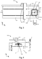
Figure 3 is a top plan view of a machine tool with a storage system for tools according to a second embodiment of the invention; and -
Figure 4 is a front view of the machine shown inFigure 3 . - The similar parts will be indicated in the various drawings with the same numerical references.
- With reference to the
Figures 2 and3 , thenumeral 1 denotes a machine tool for machining wooden panels. - The
machine tool 1 comprises a base 2, on which is provided aworking plane 3 which extends, in a preferential manner, along a first axis X and is defined by a firstouter edge 3a directed substantially according to the first axis X, and a secondouter edge 3b parallel to and opposite the latter, afront edge 3c directed substantially perpendicularly to theouter edges rear edge 3d parallel to and opposite thefront edge 3c. - The working
plane 3 is equipped with a blocking system for blocking on theworking plane 3 the panels to be machined. - The above-mentioned blocking system can comprise, for example, a plurality suction cups positioned in such a way as to be able to attach to the lower face of the panels to be machined, or a plurality of clamps configured in such a way as to be able to grip the two outer edges of the panels to secure them.
- Alternatively, the blocking system may comprise a vacuum pump for generating a negative pressure beneath the working
plane 3, in which are provided a plurality of through holes for allowing the negative pressure generated in this way to reach the panels to be machined and block them by attraction on the workingsurface 3. - Above the
working plane 3 there is a bridge, that is to say, a gantry, 4 which is movable according to the first axis X, on which is mounted anoperating head 5 movable along a second axis Y and a third axis Z. - The first axis X, the second axis Y and the third axis Z form a set of three Cartesian axes at right angles.
- The
operating head 5 is equipped with arotary spindle 6 for allowing the gripping of a tool (not illustrated) for machining panels positioned on the workingplane 3. - The
machine tool 1 is also equipped with an apparatus forhousing tools 7, also called the storage system for tools, designed to house various tools for the performance of various machining operations on the panels by theoperating head 5. - The apparatus for
housing tools 7 has, in plan, substantially the shape of a triangle with afirst side 7a positioned substantially parallel to said firstouter edge 3a and close to a zone of the latter in such a way as to be easily reachable by an operator P who wants to load or unload one or more tools from the apparatus forhousing tools 7. - A
second side 7b of the above-mentioned triangle is, on the other hand, positioned substantially according to the above-mentioned second axis Y inside the borders of theworking plane 3 and facing towards thebridge 4 in such a way as to be easily reachable by theoperating head 5 for gripping and arranging the tools in the apparatus forhousing tools 7. - The apparatus for
housing tools 7 comprises amovement system 8 consisting of achain 9, or other flexible connection member, wound on twoplain wheels 10, that is to say, without teeth, and wound and engaged on agear wheel 10d, wherein said threewheels - The
movement system 8 also comprises a motor unit for rotating the above-mentionedgear wheel 10d about itself, in such a way as to move thechain 9 along the perimeter of the triangle. - According to a variant of this embodiment of the invention, the above-mentioned two
plain wheels 10 could also be toothed and engaged with thechain 9. - The
chain 9 is fitted with a plurality ofhousing members 11 each configured for housing a tool, that is to say, a tool holder. - More specifically, each
housing member 11 has substantially the shape of a fork with the concavity facing towards the outside of the apparatus forhousing tools 7. - The
movement system 8 described above therefore allows the tools positioned on thehousing members 11 to be fed along the perimeter of the apparatus forhousing tools 7. - For this reason, thanks to the operation of the
movement system 8, the tools loaded by the operator on thehousing members 11 corresponding to theside 7a of the apparatus forhousing tools 7 can be dragged, that is to say moved, to theside 7b to allow the relative picking up by theoperating head 5. - The apparatus for
housing tools 7 can, if necessary, comprise a further twoupper housing members 12 for housing tools, positioned above theperimeter housing members 11 described above. - The
upper housing members 12 can be connected to a special dedicated movement system, configured in such a way as to move them, when changing the tool, along the first axis X towards thebridge 4 for favouring the picking up or arranging of the tools by theoperating head 5. - According to a variant of the embodiment just described, the
machine tool 1 can also comprise two or more apparatuses forhousing tools 7 of the type described above, positioned one above the other and equipped with a single movement system or with dedicated movement systems. - According to a further variant, the
machine tool 1 can be equipped with two or more apparatuses forhousing tools 7 positioned in different zones of the workingplane 3, preferably close thefront edge 3c and therear edge 3d of the workingplane 3 with therespective sides 7b facing each other. - With reference, on the other hand, to
Figures 3 and 4 , thenumeral 100 indicates a second machine tool according to the invention. - The
second machine tool 100 is identical to themachine tool 1 described above, with the exception of the apparatus for housing tools. - As in the
machine tool 1 described above, thesecond machine tool 100 also comprises abase 102, aworking plane 103 with the relative blocking system for blocking the panels to be machined, abridge 104 which is movable along a first axis X' and anoperating head 105 which is movable along a second axis Y' and a third axis Z' is equipped with arotary spindle 106. - Moreover, also in this case the
working plane 103 extends, in a preferential manner, along the first axis X' and is defined by a firstouter edge 103a directed substantially according to the first axis X', a secondouter edge 103b parallel to and opposite the latter, afront edge 103c directed substantially perpendicularly to theouter edges front edge 103c. - However, the
second machine tool 100 comprises an apparatus forhousing tools 107 different from the apparatus forhousing tools 7 described above with regard tomachine tool 1. - More specifically, the apparatus for
housing tools 107 has, in plan, substantially the shape of a square with aside 107a oriented according to the first axis X' and positioned close to a zone of the firstouter edge 103a of theworking plane 103, in such a way as to be easily reachable by an operator P' who wants to load or unload one or more tools from the apparatus forhousing tools 107. - A
second side 107b of the above-mentioned square is, on the other hand, oriented substantially according to the second axis Y' inside the borders of theworking plane 103 and facing towards thebridge 104 in such a way as to be easily reachable by theoperating head 105 for gripping and arranging the tools in the apparatus forhousing tools 107. - On the four sides of the apparatus for
housing tools 107 is also provided a plurality ofhousing members 111 each for housing a tool, that is to say, a tool holder. - More specifically, the
housing members 111 are similar in shape to those planned for themachine tool 1. - The apparatus for
housing tools 107 also comprises a motor-drivenrotation system 108 which is able to rotate theapparatus 107 about itself, through angular movements of 90°, about an axis of rotation A parallel to the third axis Z'. - According to a variant of the
second machine tool 100, as an alternative to therotation system 108 illustrated above, there may be a different movement system (not shown) similar to that described with regard tomachine tool 1, that is to say, formed by a chain wrapped around and engaged on four gear wheels positioned at the corners of the above-mentioned square, and moved along the perimeter of the square by motor means. - The apparatus for
housing tools 107 can, if necessary, comprise a furtherupper housing member 112 for housing tools, positioned higher than theperimeter housing members 111 described above. - The
upper housing member 112 can be connected to a special dedicated movement system, configured in such a way as to move it, when changing the tool, along the first axis X' towards thebridge 104 for favouring the picking up or arranging of the tools by theoperating head 105. - The
rotation system 108, which allows the rotation about the above-mentioned rotation axis A, also acts on the sameupper housing member 112. - According to a variant of the embodiment just described, the
second machine tool 100 can also comprise two or more apparatuses forhousing tools 107 of the type described above, positioned one above the other and equipped with a single rotation system or with dedicated rotation systems. - According to a further variant, the
second machine tool 100 can be equipped with two or more apparatuses forhousing tools 107 positioned in different zones of the workingplane 103, preferably close thefront edge 103c and the rear edge 103d of the workingplane 103 with the respectivesecond sides 107b facing each other. - According to further embodiments of the invention not shown in the accompanying drawings, the orthogonal projection of the above-mentioned apparatuses for housing tools on the relative working plane can have any polygonal shape, also different from a triangle or a square.
- As may be inferred from the above description, the machine tools according to the description have storage systems for tools configured in such a way as to render particularly easy and safe the operations for loading and unloading tools by operators and also the operations for picking up and arranging tools by the operating head.
- This invention is described by way of example only, without limiting the scope of application, according to its preferred embodiments, but it shall be understood that the invention may be modified and/or adapted by experts in the field without thereby departing from the scope of the inventive concept, as defined in the claims herein.
Claims (12)
- Machine tool (1, 100) for machining panels or similar pieces, comprising:a working plane (3, 103) for providing rest, in use, to at least one panel or one similar piece, said working plane (3, 103) extending according to a second axis (Y, Y') and a first axis (X, X') perpendicular to said second axis (Y, Y'), at least one first outer edge (3a, 103a) being defined in said working plane (3, 103);operating means (5, 105) movable at least according to said first axis (X, X') on said working plane (3, 103) and configured for coupling in use, in a movable manner, to at least one tool for performing at least one machining on said at least one panel or similar piece;at least one apparatus for housing tools (7, 107) for housing said at least one tool, at least a first substantially straight side (7a, 107a) and at least a second substantially straight side (7b, 107b) being defined in said at least one apparatus for housing tools (7, 107), a plurality of housing members (11, 111) for housing, in use, at least one tool being provided in said at least one first side (7a, 107a) and said at least second side (7b, 107b); andmoving means for moving at least one housing member (11, 111) between a first position facing said at least one first outer edge (3a, 103a) such that said at least one housing member (11, 111) is reachable, in use, by an operator for loading or unloading at least one tool, and a second position facing said operating means (5, 105) for allowing said operating means (5, 105) to take and/or release said at least one tool.
- Machine tool (1, 100) according to claim 1, characterized in that said first position of said at least one housing member (11, 111) is substantially aligned with said at least one first outer edge (3a, 103a).
- Machine tool (1, 100) according to claim 1 or 2, characterized in that said at least one second side (7b, 107b) is substantially orthogonal to said at least one first side (7a, 107a).
- Machine tool (1, 100) according to any one of the preceding claims, characterized in that the orthogonal projection of said at least one apparatus for housing tools (7, 107) on said working plane (3, 103) has a substantially polygonal shape.
- Machine tool (1, 100) according to claim 4, characterized in that the orthogonal projection of said at least one apparatus for housing tools (7, 107) on said working plane (3, 103) has a substantially triangular or quadrangular shape.
- Machine tool (100) according to any one of the preceding claims, characterized in that said plurality of housing members (111) is fixed on said first side (107a) and said second side (107b) of said at least one apparatus for housing tools (107), and in that said moving means comprise driving means for driving said at least one apparatus for housing tools (107) in rotation around a third axis (Z') perpendicular to said first axis (X') and said second axis (Y').
- Machine tool (100) according to claim 6 characterized in that said at least one apparatus for housing tools (107) is enabled to rotate around said third axis (Z') at angles of 90°.
- Machine tool (1) according to any one of claims 1 to 5, characterized in that said moving means comprise:at least three wheels (10, 10d) of which at least one wheel is toothed (10d), lying on a third plane parallel to said first axis (X) and said second axis (Y),at least one flexible transmission member (9) arranged on said third plane and wrapped around said at least three wheels (10, 10d), said at least one flexible transmission member (9) being geared with said at least one toothed wheel (10d) and connected to said plurality of housing members (11), anddriving means for driving in rotation said at least one toothed wheel (10d).
- Machine tool (1, 100) according to any one of the preceding claims, characterized in that said at least one first outer edge (3a, 103a) is substantially parallel to said first axis (X, X').
- Machine tool (1, 100) according to any one of the preceding claims, characterized in that said first side (7a, 107a) and said second side (7b, 107b) are parallel to said first axis (X, X') or said second axis (Y, Y').
- Machine tool (1, 100) according to any one of the preceding claims, characterized in that said at least one apparatus for housing tools (7, 107) comprises at least one housing member (11, 111) arranged on a first plane and at least a second housing member (11, 111) arranged on a second plane, said first plane and said second plane being separated from each other and substantially orthogonal to a third axis (Z, Z') perpendicular to said first axis (X, X') and said second axis (Y, Y').
- Machine tool (1, 100) according to any one of the preceding claims, characterized in that a second outer edge (3c, 103c) and a third outer edge (3d, 103d) both incident to said at least one first outer edge (3a, 103a) are defined in said working plane (3, 103) and in that said machine tool (1, 100) comprises a first apparatus for housing tools (7, 107) arranged corresponding to said second outer edge (3c, 103c) and/or a second apparatus for housing tools arranged corresponding to said third outer edge (3d, 103d).
Applications Claiming Priority (1)
| Application Number | Priority Date | Filing Date | Title |
|---|---|---|---|
| IT201800001947A IT201800001947A1 (en) | 2018-01-26 | 2018-01-26 | Machine tool with improved tool magazine. |
Publications (2)
| Publication Number | Publication Date |
|---|---|
| EP3517266A1 true EP3517266A1 (en) | 2019-07-31 |
| EP3517266B1 EP3517266B1 (en) | 2023-04-05 |
Family
ID=62089879
Family Applications (1)
| Application Number | Title | Priority Date | Filing Date |
|---|---|---|---|
| EP18211244.1A Active EP3517266B1 (en) | 2018-01-26 | 2018-12-10 | Machine tool with an improved tool storage |
Country Status (2)
| Country | Link |
|---|---|
| EP (1) | EP3517266B1 (en) |
| IT (1) | IT201800001947A1 (en) |
Families Citing this family (1)
| Publication number | Priority date | Publication date | Assignee | Title |
|---|---|---|---|---|
| DE102024130583A1 (en) * | 2024-10-21 | 2026-04-23 | Weinmann Holzbausystemtechnik Gmbh | Device and method for processing workpieces with a stationary storage station for assemblies for process automation |
Citations (9)
| Publication number | Priority date | Publication date | Assignee | Title |
|---|---|---|---|---|
| US3818580A (en) * | 1970-08-28 | 1974-06-25 | Olivetti & Co Spa | Machine tool with automatic tool-change |
| DE3139151A1 (en) * | 1980-10-03 | 1982-04-15 | Pear-Meccaniche Arrigo Pecchioli dei F.lli Pecchioli S.n.c., Firenze | Machine tool, in particular a milling machine |
| DE4015460A1 (en) * | 1990-05-14 | 1991-11-21 | Wanderer Maschinen Gmbh | Magazine for workshop tools - comprises several polygonal discs recessed around perimeter and vertical guide rod with elevating arm |
| DE19518965A1 (en) * | 1995-05-23 | 1996-11-28 | Homag Maschinenbau Ag | Machining centre for wood and plastics |
| DE10021684A1 (en) * | 1999-05-06 | 2000-11-09 | Biesse Spa | Machine for processing tables from wood or similar material includes an elongated base, a surface to support tables, a carrier bar with a vertical support connected to guides and an actuator to move the vertical support. |
| NL1012407C1 (en) * | 1999-06-22 | 2000-12-28 | Schepers Mr Franciscus Henricus | Universal CNC workstation with cutting heads mounted on either side of central beam to allow faster operation and reduced bearing wear |
| DE20019582U1 (en) * | 2000-11-17 | 2001-02-08 | MKM International GmbH Maschinenbau, 32547 Bad Oeynhausen | Processing machine, in particular woodworking machine |
| DE102008029074A1 (en) * | 2007-06-12 | 2009-01-08 | Scm Group S.P.A. | Numerically-controlled, wood-milling machining center for e.g. edge-finishing and cutting decorative motifs, has five-axis machining head sharing guides with tool shuttle |
| CN103465082B (en) * | 2013-08-26 | 2016-08-10 | 安徽省鸿庆精机有限公司 | Three main shaft digital controlled processing central machine tool magazine tool structures |
Family Cites Families (1)
| Publication number | Priority date | Publication date | Assignee | Title |
|---|---|---|---|---|
| DE102012207093A1 (en) * | 2012-04-27 | 2013-10-31 | Homag Holzbearbeitungssysteme Gmbh | Machining device with tool change arrangement, in particular chain changer |
-
2018
- 2018-01-26 IT IT201800001947A patent/IT201800001947A1/en unknown
- 2018-12-10 EP EP18211244.1A patent/EP3517266B1/en active Active
Patent Citations (9)
| Publication number | Priority date | Publication date | Assignee | Title |
|---|---|---|---|---|
| US3818580A (en) * | 1970-08-28 | 1974-06-25 | Olivetti & Co Spa | Machine tool with automatic tool-change |
| DE3139151A1 (en) * | 1980-10-03 | 1982-04-15 | Pear-Meccaniche Arrigo Pecchioli dei F.lli Pecchioli S.n.c., Firenze | Machine tool, in particular a milling machine |
| DE4015460A1 (en) * | 1990-05-14 | 1991-11-21 | Wanderer Maschinen Gmbh | Magazine for workshop tools - comprises several polygonal discs recessed around perimeter and vertical guide rod with elevating arm |
| DE19518965A1 (en) * | 1995-05-23 | 1996-11-28 | Homag Maschinenbau Ag | Machining centre for wood and plastics |
| DE10021684A1 (en) * | 1999-05-06 | 2000-11-09 | Biesse Spa | Machine for processing tables from wood or similar material includes an elongated base, a surface to support tables, a carrier bar with a vertical support connected to guides and an actuator to move the vertical support. |
| NL1012407C1 (en) * | 1999-06-22 | 2000-12-28 | Schepers Mr Franciscus Henricus | Universal CNC workstation with cutting heads mounted on either side of central beam to allow faster operation and reduced bearing wear |
| DE20019582U1 (en) * | 2000-11-17 | 2001-02-08 | MKM International GmbH Maschinenbau, 32547 Bad Oeynhausen | Processing machine, in particular woodworking machine |
| DE102008029074A1 (en) * | 2007-06-12 | 2009-01-08 | Scm Group S.P.A. | Numerically-controlled, wood-milling machining center for e.g. edge-finishing and cutting decorative motifs, has five-axis machining head sharing guides with tool shuttle |
| CN103465082B (en) * | 2013-08-26 | 2016-08-10 | 安徽省鸿庆精机有限公司 | Three main shaft digital controlled processing central machine tool magazine tool structures |
Also Published As
| Publication number | Publication date |
|---|---|
| EP3517266B1 (en) | 2023-04-05 |
| IT201800001947A1 (en) | 2019-07-26 |
Similar Documents
| Publication | Publication Date | Title |
|---|---|---|
| JP4668427B2 (en) | Automatic bending system and manipulator for this system | |
| CN106061690B (en) | Robots, and Robot Cells | |
| KR101969206B1 (en) | Robot cell | |
| US9868181B2 (en) | Assembly equipment and assembly method | |
| KR101982354B1 (en) | Robot hand | |
| US10328607B2 (en) | Machine for cutting stone material | |
| US7331093B2 (en) | Pieces hold-unit for workstations, transfer machines and like | |
| CN101284379A (en) | Manipulator assembly | |
| ITMI20150580A1 (en) | MACHINE FOR PROCESSING SHEET MATERIALS | |
| CN106061687B (en) | Workpiece inversion support device and robot cell equipped with the same | |
| EP3517266B1 (en) | Machine tool with an improved tool storage | |
| JP5732855B2 (en) | Work transfer device | |
| TW202335783A (en) | Device for loading and unloading machines for gear processing | |
| JPH04336944A (en) | Plate processing machine | |
| KR20140123686A (en) | A Tilting Table | |
| EP3626389B1 (en) | Device for the movement of pieces in a machine tool | |
| JP2005066762A (en) | Carrier robot | |
| IT201800006939A1 (en) | Improved multi-axis milling machine. | |
| JPWO2018051476A1 (en) | Automatic work carrier | |
| CN223819746U (en) | Door frame angle sawing device | |
| CN113498367A (en) | Clamping machine for articles | |
| JPH029545A (en) | Machine tool | |
| US12558749B2 (en) | Positioning apparatus and system | |
| JP2022079173A (en) | Conveyance device | |
| KR101969432B1 (en) | conveyer board for a car-seat |
Legal Events
| Date | Code | Title | Description |
|---|---|---|---|
| PUAI | Public reference made under article 153(3) epc to a published international application that has entered the european phase |
Free format text: ORIGINAL CODE: 0009012 |
|
| STAA | Information on the status of an ep patent application or granted ep patent |
Free format text: STATUS: THE APPLICATION HAS BEEN PUBLISHED |
|
| AK | Designated contracting states |
Kind code of ref document: A1 Designated state(s): AL AT BE BG CH CY CZ DE DK EE ES FI FR GB GR HR HU IE IS IT LI LT LU LV MC MK MT NL NO PL PT RO RS SE SI SK SM TR |
|
| AX | Request for extension of the european patent |
Extension state: BA ME |
|
| STAA | Information on the status of an ep patent application or granted ep patent |
Free format text: STATUS: REQUEST FOR EXAMINATION WAS MADE |
|
| STAA | Information on the status of an ep patent application or granted ep patent |
Free format text: STATUS: EXAMINATION IS IN PROGRESS |
|
| 17P | Request for examination filed |
Effective date: 20200128 |
|
| RBV | Designated contracting states (corrected) |
Designated state(s): AL AT BE BG CH CY CZ DE DK EE ES FI FR GB GR HR HU IE IS IT LI LT LU LV MC MK MT NL NO PL PT RO RS SE SI SK SM TR |
|
| 17Q | First examination report despatched |
Effective date: 20200213 |
|
| GRAP | Despatch of communication of intention to grant a patent |
Free format text: ORIGINAL CODE: EPIDOSNIGR1 |
|
| STAA | Information on the status of an ep patent application or granted ep patent |
Free format text: STATUS: GRANT OF PATENT IS INTENDED |
|
| INTG | Intention to grant announced |
Effective date: 20221027 |
|
| GRAS | Grant fee paid |
Free format text: ORIGINAL CODE: EPIDOSNIGR3 |
|
| GRAA | (expected) grant |
Free format text: ORIGINAL CODE: 0009210 |
|
| STAA | Information on the status of an ep patent application or granted ep patent |
Free format text: STATUS: THE PATENT HAS BEEN GRANTED |
|
| AK | Designated contracting states |
Kind code of ref document: B1 Designated state(s): AL AT BE BG CH CY CZ DE DK EE ES FI FR GB GR HR HU IE IS IT LI LT LU LV MC MK MT NL NO PL PT RO RS SE SI SK SM TR |
|
| REG | Reference to a national code |
Ref country code: GB Ref legal event code: FG4D |
|
| REG | Reference to a national code |
Ref country code: CH Ref legal event code: EP |
|
| REG | Reference to a national code |
Ref country code: AT Ref legal event code: REF Ref document number: 1557893 Country of ref document: AT Kind code of ref document: T Effective date: 20230415 |
|
| REG | Reference to a national code |
Ref country code: DE Ref legal event code: R096 Ref document number: 602018047993 Country of ref document: DE |
|
| REG | Reference to a national code |
Ref country code: IE Ref legal event code: FG4D |
|
| P01 | Opt-out of the competence of the unified patent court (upc) registered |
Effective date: 20230518 |
|
| REG | Reference to a national code |
Ref country code: LT Ref legal event code: MG9D |
|
| REG | Reference to a national code |
Ref country code: NL Ref legal event code: MP Effective date: 20230405 |
|
| PG25 | Lapsed in a contracting state [announced via postgrant information from national office to epo] |
Ref country code: NL Free format text: LAPSE BECAUSE OF FAILURE TO SUBMIT A TRANSLATION OF THE DESCRIPTION OR TO PAY THE FEE WITHIN THE PRESCRIBED TIME-LIMIT Effective date: 20230405 |
|
| PG25 | Lapsed in a contracting state [announced via postgrant information from national office to epo] |
Ref country code: SE Free format text: LAPSE BECAUSE OF FAILURE TO SUBMIT A TRANSLATION OF THE DESCRIPTION OR TO PAY THE FEE WITHIN THE PRESCRIBED TIME-LIMIT Effective date: 20230405 Ref country code: PT Free format text: LAPSE BECAUSE OF FAILURE TO SUBMIT A TRANSLATION OF THE DESCRIPTION OR TO PAY THE FEE WITHIN THE PRESCRIBED TIME-LIMIT Effective date: 20230807 Ref country code: NO Free format text: LAPSE BECAUSE OF FAILURE TO SUBMIT A TRANSLATION OF THE DESCRIPTION OR TO PAY THE FEE WITHIN THE PRESCRIBED TIME-LIMIT Effective date: 20230705 Ref country code: ES Free format text: LAPSE BECAUSE OF FAILURE TO SUBMIT A TRANSLATION OF THE DESCRIPTION OR TO PAY THE FEE WITHIN THE PRESCRIBED TIME-LIMIT Effective date: 20230405 |
|
| PG25 | Lapsed in a contracting state [announced via postgrant information from national office to epo] |
Ref country code: RS Free format text: LAPSE BECAUSE OF FAILURE TO SUBMIT A TRANSLATION OF THE DESCRIPTION OR TO PAY THE FEE WITHIN THE PRESCRIBED TIME-LIMIT Effective date: 20230405 Ref country code: PL Free format text: LAPSE BECAUSE OF FAILURE TO SUBMIT A TRANSLATION OF THE DESCRIPTION OR TO PAY THE FEE WITHIN THE PRESCRIBED TIME-LIMIT Effective date: 20230405 Ref country code: LV Free format text: LAPSE BECAUSE OF FAILURE TO SUBMIT A TRANSLATION OF THE DESCRIPTION OR TO PAY THE FEE WITHIN THE PRESCRIBED TIME-LIMIT Effective date: 20230405 Ref country code: LT Free format text: LAPSE BECAUSE OF FAILURE TO SUBMIT A TRANSLATION OF THE DESCRIPTION OR TO PAY THE FEE WITHIN THE PRESCRIBED TIME-LIMIT Effective date: 20230405 Ref country code: IS Free format text: LAPSE BECAUSE OF FAILURE TO SUBMIT A TRANSLATION OF THE DESCRIPTION OR TO PAY THE FEE WITHIN THE PRESCRIBED TIME-LIMIT Effective date: 20230805 Ref country code: HR Free format text: LAPSE BECAUSE OF FAILURE TO SUBMIT A TRANSLATION OF THE DESCRIPTION OR TO PAY THE FEE WITHIN THE PRESCRIBED TIME-LIMIT Effective date: 20230405 Ref country code: GR Free format text: LAPSE BECAUSE OF FAILURE TO SUBMIT A TRANSLATION OF THE DESCRIPTION OR TO PAY THE FEE WITHIN THE PRESCRIBED TIME-LIMIT Effective date: 20230706 Ref country code: AL Free format text: LAPSE BECAUSE OF FAILURE TO SUBMIT A TRANSLATION OF THE DESCRIPTION OR TO PAY THE FEE WITHIN THE PRESCRIBED TIME-LIMIT Effective date: 20230405 |
|
| PG25 | Lapsed in a contracting state [announced via postgrant information from national office to epo] |
Ref country code: FI Free format text: LAPSE BECAUSE OF FAILURE TO SUBMIT A TRANSLATION OF THE DESCRIPTION OR TO PAY THE FEE WITHIN THE PRESCRIBED TIME-LIMIT Effective date: 20230405 |
|
| REG | Reference to a national code |
Ref country code: DE Ref legal event code: R097 Ref document number: 602018047993 Country of ref document: DE |
|
| REG | Reference to a national code |
Ref country code: AT Ref legal event code: UEP Ref document number: 1557893 Country of ref document: AT Kind code of ref document: T Effective date: 20230405 |
|
| PG25 | Lapsed in a contracting state [announced via postgrant information from national office to epo] |
Ref country code: SK Free format text: LAPSE BECAUSE OF FAILURE TO SUBMIT A TRANSLATION OF THE DESCRIPTION OR TO PAY THE FEE WITHIN THE PRESCRIBED TIME-LIMIT Effective date: 20230405 |
|
| PG25 | Lapsed in a contracting state [announced via postgrant information from national office to epo] |
Ref country code: SM Free format text: LAPSE BECAUSE OF FAILURE TO SUBMIT A TRANSLATION OF THE DESCRIPTION OR TO PAY THE FEE WITHIN THE PRESCRIBED TIME-LIMIT Effective date: 20230405 Ref country code: SK Free format text: LAPSE BECAUSE OF FAILURE TO SUBMIT A TRANSLATION OF THE DESCRIPTION OR TO PAY THE FEE WITHIN THE PRESCRIBED TIME-LIMIT Effective date: 20230405 Ref country code: RO Free format text: LAPSE BECAUSE OF FAILURE TO SUBMIT A TRANSLATION OF THE DESCRIPTION OR TO PAY THE FEE WITHIN THE PRESCRIBED TIME-LIMIT Effective date: 20230405 Ref country code: EE Free format text: LAPSE BECAUSE OF FAILURE TO SUBMIT A TRANSLATION OF THE DESCRIPTION OR TO PAY THE FEE WITHIN THE PRESCRIBED TIME-LIMIT Effective date: 20230405 Ref country code: DK Free format text: LAPSE BECAUSE OF FAILURE TO SUBMIT A TRANSLATION OF THE DESCRIPTION OR TO PAY THE FEE WITHIN THE PRESCRIBED TIME-LIMIT Effective date: 20230405 Ref country code: CZ Free format text: LAPSE BECAUSE OF FAILURE TO SUBMIT A TRANSLATION OF THE DESCRIPTION OR TO PAY THE FEE WITHIN THE PRESCRIBED TIME-LIMIT Effective date: 20230405 |
|
| PLBE | No opposition filed within time limit |
Free format text: ORIGINAL CODE: 0009261 |
|
| STAA | Information on the status of an ep patent application or granted ep patent |
Free format text: STATUS: NO OPPOSITION FILED WITHIN TIME LIMIT |
|
| 26N | No opposition filed |
Effective date: 20240108 |
|
| PG25 | Lapsed in a contracting state [announced via postgrant information from national office to epo] |
Ref country code: SI Free format text: LAPSE BECAUSE OF FAILURE TO SUBMIT A TRANSLATION OF THE DESCRIPTION OR TO PAY THE FEE WITHIN THE PRESCRIBED TIME-LIMIT Effective date: 20230405 |
|
| PG25 | Lapsed in a contracting state [announced via postgrant information from national office to epo] |
Ref country code: SI Free format text: LAPSE BECAUSE OF FAILURE TO SUBMIT A TRANSLATION OF THE DESCRIPTION OR TO PAY THE FEE WITHIN THE PRESCRIBED TIME-LIMIT Effective date: 20230405 |
|
| REG | Reference to a national code |
Ref country code: CH Ref legal event code: PL |
|
| PG25 | Lapsed in a contracting state [announced via postgrant information from national office to epo] |
Ref country code: LU Free format text: LAPSE BECAUSE OF NON-PAYMENT OF DUE FEES Effective date: 20231210 |
|
| PG25 | Lapsed in a contracting state [announced via postgrant information from national office to epo] |
Ref country code: MC Free format text: LAPSE BECAUSE OF FAILURE TO SUBMIT A TRANSLATION OF THE DESCRIPTION OR TO PAY THE FEE WITHIN THE PRESCRIBED TIME-LIMIT Effective date: 20230405 |
|
| GBPC | Gb: european patent ceased through non-payment of renewal fee |
Effective date: 20231210 |
|
| REG | Reference to a national code |
Ref country code: BE Ref legal event code: MM Effective date: 20231231 |
|
| PG25 | Lapsed in a contracting state [announced via postgrant information from national office to epo] |
Ref country code: MC Free format text: LAPSE BECAUSE OF FAILURE TO SUBMIT A TRANSLATION OF THE DESCRIPTION OR TO PAY THE FEE WITHIN THE PRESCRIBED TIME-LIMIT Effective date: 20230405 Ref country code: LU Free format text: LAPSE BECAUSE OF NON-PAYMENT OF DUE FEES Effective date: 20231210 |
|
| REG | Reference to a national code |
Ref country code: IE Ref legal event code: MM4A |
|
| PG25 | Lapsed in a contracting state [announced via postgrant information from national office to epo] |
Ref country code: IE Free format text: LAPSE BECAUSE OF NON-PAYMENT OF DUE FEES Effective date: 20231210 |
|
| PG25 | Lapsed in a contracting state [announced via postgrant information from national office to epo] |
Ref country code: GB Free format text: LAPSE BECAUSE OF NON-PAYMENT OF DUE FEES Effective date: 20231210 |
|
| PG25 | Lapsed in a contracting state [announced via postgrant information from national office to epo] |
Ref country code: BE Free format text: LAPSE BECAUSE OF NON-PAYMENT OF DUE FEES Effective date: 20231231 |
|
| PG25 | Lapsed in a contracting state [announced via postgrant information from national office to epo] |
Ref country code: FR Free format text: LAPSE BECAUSE OF NON-PAYMENT OF DUE FEES Effective date: 20231231 |
|
| PG25 | Lapsed in a contracting state [announced via postgrant information from national office to epo] |
Ref country code: CH Free format text: LAPSE BECAUSE OF NON-PAYMENT OF DUE FEES Effective date: 20231231 |
|
| PG25 | Lapsed in a contracting state [announced via postgrant information from national office to epo] |
Ref country code: IE Free format text: LAPSE BECAUSE OF NON-PAYMENT OF DUE FEES Effective date: 20231210 Ref country code: GB Free format text: LAPSE BECAUSE OF NON-PAYMENT OF DUE FEES Effective date: 20231210 Ref country code: FR Free format text: LAPSE BECAUSE OF NON-PAYMENT OF DUE FEES Effective date: 20231231 Ref country code: CH Free format text: LAPSE BECAUSE OF NON-PAYMENT OF DUE FEES Effective date: 20231231 Ref country code: BE Free format text: LAPSE BECAUSE OF NON-PAYMENT OF DUE FEES Effective date: 20231231 |
|
| PG25 | Lapsed in a contracting state [announced via postgrant information from national office to epo] |
Ref country code: BG Free format text: LAPSE BECAUSE OF FAILURE TO SUBMIT A TRANSLATION OF THE DESCRIPTION OR TO PAY THE FEE WITHIN THE PRESCRIBED TIME-LIMIT Effective date: 20230405 |
|
| PG25 | Lapsed in a contracting state [announced via postgrant information from national office to epo] |
Ref country code: BG Free format text: LAPSE BECAUSE OF FAILURE TO SUBMIT A TRANSLATION OF THE DESCRIPTION OR TO PAY THE FEE WITHIN THE PRESCRIBED TIME-LIMIT Effective date: 20230405 |
|
| PG25 | Lapsed in a contracting state [announced via postgrant information from national office to epo] |
Ref country code: CY Free format text: LAPSE BECAUSE OF FAILURE TO SUBMIT A TRANSLATION OF THE DESCRIPTION OR TO PAY THE FEE WITHIN THE PRESCRIBED TIME-LIMIT; INVALID AB INITIO Effective date: 20181210 |
|
| PG25 | Lapsed in a contracting state [announced via postgrant information from national office to epo] |
Ref country code: HU Free format text: LAPSE BECAUSE OF FAILURE TO SUBMIT A TRANSLATION OF THE DESCRIPTION OR TO PAY THE FEE WITHIN THE PRESCRIBED TIME-LIMIT; INVALID AB INITIO Effective date: 20181210 |
|
| PG25 | Lapsed in a contracting state [announced via postgrant information from national office to epo] |
Ref country code: TR Free format text: LAPSE BECAUSE OF FAILURE TO SUBMIT A TRANSLATION OF THE DESCRIPTION OR TO PAY THE FEE WITHIN THE PRESCRIBED TIME-LIMIT Effective date: 20230405 |
|
| PGFP | Annual fee paid to national office [announced via postgrant information from national office to epo] |
Ref country code: AT Payment date: 20251215 Year of fee payment: 8 |
|
| PGFP | Annual fee paid to national office [announced via postgrant information from national office to epo] |
Ref country code: IT Payment date: 20251013 Year of fee payment: 8 |
|
| PGFP | Annual fee paid to national office [announced via postgrant information from national office to epo] |
Ref country code: DE Payment date: 20251222 Year of fee payment: 8 |