EP3517155B1 - Breath actuated inhaler - Google Patents
Breath actuated inhaler Download PDFInfo
- Publication number
- EP3517155B1 EP3517155B1 EP19153824.8A EP19153824A EP3517155B1 EP 3517155 B1 EP3517155 B1 EP 3517155B1 EP 19153824 A EP19153824 A EP 19153824A EP 3517155 B1 EP3517155 B1 EP 3517155B1
- Authority
- EP
- European Patent Office
- Prior art keywords
- valve
- valve port
- boss
- breath actuated
- metered dose
- Prior art date
- Legal status (The legal status is an assumption and is not a legal conclusion. Google has not performed a legal analysis and makes no representation as to the accuracy of the status listed.)
- Active
Links
- 229940071648 metered dose inhaler Drugs 0.000 claims description 35
- 229920000642 polymer Polymers 0.000 claims description 22
- 238000007789 sealing Methods 0.000 claims description 19
- 239000003814 drug Substances 0.000 claims description 18
- 238000002347 injection Methods 0.000 claims description 13
- 239000007924 injection Substances 0.000 claims description 13
- 230000003746 surface roughness Effects 0.000 claims description 9
- 238000001746 injection moulding Methods 0.000 claims description 8
- 239000004676 acrylonitrile butadiene styrene Substances 0.000 claims description 4
- 230000004044 response Effects 0.000 claims description 4
- XECAHXYUAAWDEL-UHFFFAOYSA-N acrylonitrile butadiene styrene Chemical compound C=CC=C.C=CC#N.C=CC1=CC=CC=C1 XECAHXYUAAWDEL-UHFFFAOYSA-N 0.000 claims description 3
- 229920000122 acrylonitrile butadiene styrene Polymers 0.000 claims description 3
- 239000012528 membrane Substances 0.000 claims description 2
- 230000000717 retained effect Effects 0.000 claims 2
- LFQSCWFLJHTTHZ-UHFFFAOYSA-N Ethanol Chemical compound CCO LFQSCWFLJHTTHZ-UHFFFAOYSA-N 0.000 description 24
- 239000008186 active pharmaceutical agent Substances 0.000 description 14
- 238000000465 moulding Methods 0.000 description 13
- 239000003380 propellant Substances 0.000 description 13
- 230000006835 compression Effects 0.000 description 12
- 238000007906 compression Methods 0.000 description 12
- 229920001971 elastomer Polymers 0.000 description 12
- 239000000806 elastomer Substances 0.000 description 12
- KUVIULQEHSCUHY-XYWKZLDCSA-N Beclometasone Chemical compound C1CC2=CC(=O)C=C[C@]2(C)[C@]2(Cl)[C@@H]1[C@@H]1C[C@H](C)[C@@](C(=O)COC(=O)CC)(OC(=O)CC)[C@@]1(C)C[C@@H]2O KUVIULQEHSCUHY-XYWKZLDCSA-N 0.000 description 10
- 229950000210 beclometasone dipropionate Drugs 0.000 description 10
- 239000006184 cosolvent Substances 0.000 description 9
- 238000000034 method Methods 0.000 description 9
- 238000012360 testing method Methods 0.000 description 9
- 239000000463 material Substances 0.000 description 8
- 239000000556 agonist Substances 0.000 description 7
- NDAUXUAQIAJITI-UHFFFAOYSA-N albuterol Chemical compound CC(C)(C)NCC(O)C1=CC=C(O)C(CO)=C1 NDAUXUAQIAJITI-UHFFFAOYSA-N 0.000 description 7
- 230000002093 peripheral effect Effects 0.000 description 7
- 102100039705 Beta-2 adrenergic receptor Human genes 0.000 description 6
- 101710152983 Beta-2 adrenergic receptor Proteins 0.000 description 6
- 239000004433 Thermoplastic polyurethane Substances 0.000 description 6
- 230000015556 catabolic process Effects 0.000 description 6
- 238000006731 degradation reaction Methods 0.000 description 6
- 229920002725 thermoplastic elastomer Polymers 0.000 description 6
- 229920002803 thermoplastic polyurethane Polymers 0.000 description 6
- 229920006347 Elastollan Polymers 0.000 description 5
- 239000000443 aerosol Substances 0.000 description 5
- 239000005557 antagonist Substances 0.000 description 5
- XMIIGOLPHOKFCH-UHFFFAOYSA-N 3-phenylpropionic acid Chemical compound OC(=O)CCC1=CC=CC=C1 XMIIGOLPHOKFCH-UHFFFAOYSA-N 0.000 description 4
- -1 aliphatic alcohols Chemical class 0.000 description 4
- 239000000812 cholinergic antagonist Substances 0.000 description 4
- 150000001875 compounds Chemical class 0.000 description 4
- 239000012141 concentrate Substances 0.000 description 4
- 239000003246 corticosteroid Substances 0.000 description 4
- 238000013461 design Methods 0.000 description 4
- 150000002148 esters Chemical class 0.000 description 4
- 239000003112 inhibitor Substances 0.000 description 4
- 238000005259 measurement Methods 0.000 description 4
- 150000003839 salts Chemical class 0.000 description 4
- XLYOFNOQVPJJNP-UHFFFAOYSA-N water Substances O XLYOFNOQVPJJNP-UHFFFAOYSA-N 0.000 description 4
- CPELXLSAUQHCOX-UHFFFAOYSA-M Bromide Chemical compound [Br-] CPELXLSAUQHCOX-UHFFFAOYSA-M 0.000 description 3
- 239000003795 chemical substances by application Substances 0.000 description 3
- 229960001334 corticosteroids Drugs 0.000 description 3
- 239000000428 dust Substances 0.000 description 3
- 238000004519 manufacturing process Methods 0.000 description 3
- 239000000203 mixture Substances 0.000 description 3
- XWTYSIMOBUGWOL-UHFFFAOYSA-N (+-)-Terbutaline Chemical compound CC(C)(C)NCC(O)C1=CC(O)=CC(O)=C1 XWTYSIMOBUGWOL-UHFFFAOYSA-N 0.000 description 2
- YFMFNYKEUDLDTL-UHFFFAOYSA-N 1,1,1,2,3,3,3-heptafluoropropane Chemical compound FC(F)(F)C(F)C(F)(F)F YFMFNYKEUDLDTL-UHFFFAOYSA-N 0.000 description 2
- LVGUZGTVOIAKKC-UHFFFAOYSA-N 1,1,1,2-tetrafluoroethane Chemical compound FCC(F)(F)F LVGUZGTVOIAKKC-UHFFFAOYSA-N 0.000 description 2
- LSLYOANBFKQKPT-DIFFPNOSSA-N 5-[(1r)-1-hydroxy-2-[[(2r)-1-(4-hydroxyphenyl)propan-2-yl]amino]ethyl]benzene-1,3-diol Chemical compound C([C@@H](C)NC[C@H](O)C=1C=C(O)C=C(O)C=1)C1=CC=C(O)C=C1 LSLYOANBFKQKPT-DIFFPNOSSA-N 0.000 description 2
- 102000004127 Cytokines Human genes 0.000 description 2
- 108090000695 Cytokines Proteins 0.000 description 2
- RKUNBYITZUJHSG-UHFFFAOYSA-N Hyosciamin-hydrochlorid Natural products CN1C(C2)CCC1CC2OC(=O)C(CO)C1=CC=CC=C1 RKUNBYITZUJHSG-UHFFFAOYSA-N 0.000 description 2
- 229940121948 Muscarinic receptor antagonist Drugs 0.000 description 2
- 229940123932 Phosphodiesterase 4 inhibitor Drugs 0.000 description 2
- 102000004861 Phosphoric Diester Hydrolases Human genes 0.000 description 2
- 108090001050 Phosphoric Diester Hydrolases Proteins 0.000 description 2
- GIIZNNXWQWCKIB-UHFFFAOYSA-N Serevent Chemical compound C1=C(O)C(CO)=CC(C(O)CNCCCCCCOCCCCC=2C=CC=CC=2)=C1 GIIZNNXWQWCKIB-UHFFFAOYSA-N 0.000 description 2
- 239000000654 additive Substances 0.000 description 2
- 230000000996 additive effect Effects 0.000 description 2
- OIRDTQYFTABQOQ-KQYNXXCUSA-N adenosine Chemical compound C1=NC=2C(N)=NC=NC=2N1[C@@H]1O[C@H](CO)[C@@H](O)[C@H]1O OIRDTQYFTABQOQ-KQYNXXCUSA-N 0.000 description 2
- 229940121363 anti-inflammatory agent Drugs 0.000 description 2
- 239000002260 anti-inflammatory agent Substances 0.000 description 2
- 229940065524 anticholinergics inhalants for obstructive airway diseases Drugs 0.000 description 2
- 229940125715 antihistaminic agent Drugs 0.000 description 2
- 239000000739 antihistaminic agent Substances 0.000 description 2
- NBMKJKDGKREAPL-DVTGEIKXSA-N beclomethasone Chemical compound C1CC2=CC(=O)C=C[C@]2(C)[C@]2(Cl)[C@@H]1[C@@H]1C[C@H](C)[C@@](C(=O)CO)(O)[C@@]1(C)C[C@@H]2O NBMKJKDGKREAPL-DVTGEIKXSA-N 0.000 description 2
- 230000015572 biosynthetic process Effects 0.000 description 2
- 230000000694 effects Effects 0.000 description 2
- 229960001022 fenoterol Drugs 0.000 description 2
- 238000010304 firing Methods 0.000 description 2
- 238000011835 investigation Methods 0.000 description 2
- 229960003088 loratadine Drugs 0.000 description 2
- JCCNYMKQOSZNPW-UHFFFAOYSA-N loratadine Chemical compound C1CN(C(=O)OCC)CCC1=C1C2=NC=CC=C2CCC2=CC(Cl)=CC=C21 JCCNYMKQOSZNPW-UHFFFAOYSA-N 0.000 description 2
- 239000003595 mist Substances 0.000 description 2
- QLIIKPVHVRXHRI-CXSFZGCWSA-N mometasone Chemical compound C1CC2=CC(=O)C=C[C@]2(C)[C@]2(Cl)[C@@H]1[C@@H]1C[C@@H](C)[C@@](C(=O)CCl)(O)[C@@]1(C)C[C@@H]2O QLIIKPVHVRXHRI-CXSFZGCWSA-N 0.000 description 2
- 239000000041 non-steroidal anti-inflammatory agent Substances 0.000 description 2
- 229940021182 non-steroidal anti-inflammatory drug Drugs 0.000 description 2
- 239000000546 pharmaceutical excipient Substances 0.000 description 2
- 239000002587 phosphodiesterase IV inhibitor Substances 0.000 description 2
- 230000037452 priming Effects 0.000 description 2
- 239000000126 substance Substances 0.000 description 2
- 238000003786 synthesis reaction Methods 0.000 description 2
- 229960000195 terbutaline Drugs 0.000 description 2
- ZFXYFBGIUFBOJW-UHFFFAOYSA-N theophylline Chemical compound O=C1N(C)C(=O)N(C)C2=C1NC=N2 ZFXYFBGIUFBOJW-UHFFFAOYSA-N 0.000 description 2
- JWZZKOKVBUJMES-UHFFFAOYSA-N (+-)-Isoprenaline Chemical compound CC(C)NCC(O)C1=CC=C(O)C(O)=C1 JWZZKOKVBUJMES-UHFFFAOYSA-N 0.000 description 1
- WRIDQFICGBMAFQ-UHFFFAOYSA-N (E)-8-Octadecenoic acid Natural products CCCCCCCCCC=CCCCCCCC(O)=O WRIDQFICGBMAFQ-UHFFFAOYSA-N 0.000 description 1
- NDAUXUAQIAJITI-LBPRGKRZSA-N (R)-salbutamol Chemical compound CC(C)(C)NC[C@H](O)C1=CC=C(O)C(CO)=C1 NDAUXUAQIAJITI-LBPRGKRZSA-N 0.000 description 1
- RKUNBYITZUJHSG-FXUDXRNXSA-N (S)-atropine Chemical compound C1([C@@H](CO)C(=O)O[C@H]2C[C@H]3CC[C@@H](C2)N3C)=CC=CC=C1 RKUNBYITZUJHSG-FXUDXRNXSA-N 0.000 description 1
- OBRNDARFFFHCGE-PERKLWIXSA-N (S,S)-formoterol fumarate Chemical compound OC(=O)\C=C\C(O)=O.C1=CC(OC)=CC=C1C[C@H](C)NC[C@@H](O)C1=CC=C(O)C(NC=O)=C1.C1=CC(OC)=CC=C1C[C@H](C)NC[C@@H](O)C1=CC=C(O)C(NC=O)=C1 OBRNDARFFFHCGE-PERKLWIXSA-N 0.000 description 1
- PMGQWSIVQFOFOQ-BDUVBVHRSA-N (e)-but-2-enedioic acid;(2r)-2-[2-[1-(4-chlorophenyl)-1-phenylethoxy]ethyl]-1-methylpyrrolidine Chemical compound OC(=O)\C=C\C(O)=O.CN1CCC[C@@H]1CCOC(C)(C=1C=CC(Cl)=CC=1)C1=CC=CC=C1 PMGQWSIVQFOFOQ-BDUVBVHRSA-N 0.000 description 1
- JXYWFNAQESKDNC-BTJKTKAUSA-N (z)-4-hydroxy-4-oxobut-2-enoate;2-[(4-methoxyphenyl)methyl-pyridin-2-ylamino]ethyl-dimethylazanium Chemical compound OC(=O)\C=C/C(O)=O.C1=CC(OC)=CC=C1CN(CCN(C)C)C1=CC=CC=N1 JXYWFNAQESKDNC-BTJKTKAUSA-N 0.000 description 1
- JOROEVAWQLGPFQ-UHFFFAOYSA-N 1-benzhydryl-4-methylpiperazine;2-hydroxypropanoic acid Chemical compound CC(O)C(O)=O.C1CN(C)CCN1C(C=1C=CC=CC=1)C1=CC=CC=C1 JOROEVAWQLGPFQ-UHFFFAOYSA-N 0.000 description 1
- VSWPGAIWKHPTKX-UHFFFAOYSA-N 1-methyl-10-[2-(4-methyl-1-piperazinyl)-1-oxoethyl]-5H-thieno[3,4-b][1,5]benzodiazepin-4-one Chemical compound C1CN(C)CCN1CC(=O)N1C2=CC=CC=C2NC(=O)C2=CSC(C)=C21 VSWPGAIWKHPTKX-UHFFFAOYSA-N 0.000 description 1
- PDNHLCRMUIGNBV-UHFFFAOYSA-N 1-pyridin-2-ylethanamine Chemical compound CC(N)C1=CC=CC=N1 PDNHLCRMUIGNBV-UHFFFAOYSA-N 0.000 description 1
- GKNPSSNBBWDAGH-UHFFFAOYSA-N 2-hydroxy-2,2-diphenylacetic acid (1,1-dimethyl-3-piperidin-1-iumyl) ester Chemical compound C1[N+](C)(C)CCCC1OC(=O)C(O)(C=1C=CC=CC=1)C1=CC=CC=C1 GKNPSSNBBWDAGH-UHFFFAOYSA-N 0.000 description 1
- LQJBNNIYVWPHFW-UHFFFAOYSA-N 20:1omega9c fatty acid Natural products CCCCCCCCCCC=CCCCCCCCC(O)=O LQJBNNIYVWPHFW-UHFFFAOYSA-N 0.000 description 1
- 238000010146 3D printing Methods 0.000 description 1
- LXLHBNBFXRIZAS-UHFFFAOYSA-N 5-methylsulfanyl-1,3-diphenylpyrazole Chemical compound CSC1=CC(C=2C=CC=CC=2)=NN1C1=CC=CC=C1 LXLHBNBFXRIZAS-UHFFFAOYSA-N 0.000 description 1
- VHRSUDSXCMQTMA-PJHHCJLFSA-N 6alpha-methylprednisolone Chemical compound C([C@@]12C)=CC(=O)C=C1[C@@H](C)C[C@@H]1[C@@H]2[C@@H](O)C[C@]2(C)[C@@](O)(C(=O)CO)CC[C@H]21 VHRSUDSXCMQTMA-PJHHCJLFSA-N 0.000 description 1
- QSBYPNXLFMSGKH-UHFFFAOYSA-N 9-Heptadecensaeure Natural products CCCCCCCC=CCCCCCCCC(O)=O QSBYPNXLFMSGKH-UHFFFAOYSA-N 0.000 description 1
- 229930000680 A04AD01 - Scopolamine Natural products 0.000 description 1
- 241001106067 Atropa Species 0.000 description 1
- 229930003347 Atropine Natural products 0.000 description 1
- 229940121786 Beta 2 adrenoreceptor agonist Drugs 0.000 description 1
- VOVIALXJUBGFJZ-KWVAZRHASA-N Budesonide Chemical compound C1CC2=CC(=O)C=C[C@]2(C)[C@@H]2[C@@H]1[C@@H]1C[C@H]3OC(CCC)O[C@@]3(C(=O)CO)[C@@]1(C)C[C@@H]2O VOVIALXJUBGFJZ-KWVAZRHASA-N 0.000 description 1
- 239000002126 C01EB10 - Adenosine Substances 0.000 description 1
- 108010059108 CD18 Antigens Proteins 0.000 description 1
- 102000017927 CHRM1 Human genes 0.000 description 1
- 102000017926 CHRM2 Human genes 0.000 description 1
- ZKLPARSLTMPFCP-UHFFFAOYSA-N Cetirizine Chemical compound C1CN(CCOCC(=O)O)CCN1C(C=1C=CC(Cl)=CC=1)C1=CC=CC=C1 ZKLPARSLTMPFCP-UHFFFAOYSA-N 0.000 description 1
- 102000019034 Chemokines Human genes 0.000 description 1
- 108010012236 Chemokines Proteins 0.000 description 1
- DBAKFASWICGISY-BTJKTKAUSA-N Chlorpheniramine maleate Chemical compound OC(=O)\C=C/C(O)=O.C=1C=CC=NC=1C(CCN(C)C)C1=CC=C(Cl)C=C1 DBAKFASWICGISY-BTJKTKAUSA-N 0.000 description 1
- 101150073075 Chrm1 gene Proteins 0.000 description 1
- 101150012960 Chrm2 gene Proteins 0.000 description 1
- LUKZNWIVRBCLON-GXOBDPJESA-N Ciclesonide Chemical compound C1([C@H]2O[C@@]3([C@H](O2)C[C@@H]2[C@@]3(C[C@H](O)[C@@H]3[C@@]4(C)C=CC(=O)C=C4CC[C@H]32)C)C(=O)COC(=O)C(C)C)CCCCC1 LUKZNWIVRBCLON-GXOBDPJESA-N 0.000 description 1
- 101100135868 Dictyostelium discoideum pde3 gene Proteins 0.000 description 1
- RRJFVPUCXDGFJB-UHFFFAOYSA-N Fexofenadine hydrochloride Chemical compound Cl.C1=CC(C(C)(C(O)=O)C)=CC=C1C(O)CCCN1CCC(C(O)(C=2C=CC=CC=2)C=2C=CC=CC=2)CC1 RRJFVPUCXDGFJB-UHFFFAOYSA-N 0.000 description 1
- VPNYRYCIDCJBOM-UHFFFAOYSA-M Glycopyrronium bromide Chemical compound [Br-].C1[N+](C)(C)CCC1OC(=O)C(O)(C=1C=CC=CC=1)C1CCCC1 VPNYRYCIDCJBOM-UHFFFAOYSA-M 0.000 description 1
- ZRYHPQCHHOKSMD-UHFFFAOYSA-N Hexocyclium Chemical compound C1C[N+](C)(C)CCN1CC(O)(C=1C=CC=CC=1)C1CCCCC1 ZRYHPQCHHOKSMD-UHFFFAOYSA-N 0.000 description 1
- 102000003834 Histamine H1 Receptors Human genes 0.000 description 1
- 108090000110 Histamine H1 Receptors Proteins 0.000 description 1
- ZTVIKZXZYLEVOL-MCOXGKPRSA-N Homatropine Chemical compound O([C@H]1C[C@H]2CC[C@@H](C1)N2C)C(=O)C(O)C1=CC=CC=C1 ZTVIKZXZYLEVOL-MCOXGKPRSA-N 0.000 description 1
- STECJAGHUSJQJN-GAUPFVANSA-N Hyoscine Natural products C1([C@H](CO)C(=O)OC2C[C@@H]3N([C@H](C2)[C@@H]2[C@H]3O2)C)=CC=CC=C1 STECJAGHUSJQJN-GAUPFVANSA-N 0.000 description 1
- DHUZAAUGHUHIDS-ONEGZZNKSA-N Isomyristicin Chemical compound COC1=CC(\C=C\C)=CC2=C1OCO2 DHUZAAUGHUHIDS-ONEGZZNKSA-N 0.000 description 1
- BFSMWENDZZIWPW-UHFFFAOYSA-N Isopropamide iodide Chemical compound [I-].C=1C=CC=CC=1C(C(N)=O)(CC[N+](C)(C(C)C)C(C)C)C1=CC=CC=C1 BFSMWENDZZIWPW-UHFFFAOYSA-N 0.000 description 1
- OCJYIGYOJCODJL-UHFFFAOYSA-N Meclizine Chemical compound CC1=CC=CC(CN2CCN(CC2)C(C=2C=CC=CC=2)C=2C=CC(Cl)=CC=2)=C1 OCJYIGYOJCODJL-UHFFFAOYSA-N 0.000 description 1
- GZHFODJQISUKAY-UHFFFAOYSA-N Methantheline Chemical compound C1=CC=C2C(C(=O)OCC[N+](C)(CC)CC)C3=CC=CC=C3OC2=C1 GZHFODJQISUKAY-UHFFFAOYSA-N 0.000 description 1
- 102000014415 Muscarinic acetylcholine receptor Human genes 0.000 description 1
- 108050003473 Muscarinic acetylcholine receptor Proteins 0.000 description 1
- STECJAGHUSJQJN-UHFFFAOYSA-N N-Methyl-scopolamin Natural products C1C(C2C3O2)N(C)C3CC1OC(=O)C(CO)C1=CC=CC=C1 STECJAGHUSJQJN-UHFFFAOYSA-N 0.000 description 1
- 102100029438 Nitric oxide synthase, inducible Human genes 0.000 description 1
- 101710089543 Nitric oxide synthase, inducible Proteins 0.000 description 1
- ZQPPMHVWECSIRJ-UHFFFAOYSA-N Oleic acid Natural products CCCCCCCCC=CCCCCCCCC(O)=O ZQPPMHVWECSIRJ-UHFFFAOYSA-N 0.000 description 1
- 239000005642 Oleic acid Substances 0.000 description 1
- 229940123263 Phosphodiesterase 3 inhibitor Drugs 0.000 description 1
- VQDBNKDJNJQRDG-UHFFFAOYSA-N Pirbuterol Chemical compound CC(C)(C)NCC(O)C1=CC=C(O)C(CO)=N1 VQDBNKDJNJQRDG-UHFFFAOYSA-N 0.000 description 1
- BPZSYCZIITTYBL-YJYMSZOUSA-N R-Formoterol Chemical compound C1=CC(OC)=CC=C1C[C@@H](C)NC[C@H](O)C1=CC=C(O)C(NC=O)=C1 BPZSYCZIITTYBL-YJYMSZOUSA-N 0.000 description 1
- GUGOEEXESWIERI-UHFFFAOYSA-N Terfenadine Chemical compound C1=CC(C(C)(C)C)=CC=C1C(O)CCCN1CCC(C(O)(C=2C=CC=CC=2)C=2C=CC=CC=2)CC1 GUGOEEXESWIERI-UHFFFAOYSA-N 0.000 description 1
- UFLGIAIHIAPJJC-UHFFFAOYSA-N Tripelennamine Chemical compound C=1C=CC=NC=1N(CCN(C)C)CC1=CC=CC=C1 UFLGIAIHIAPJJC-UHFFFAOYSA-N 0.000 description 1
- BGDKAVGWHJFAGW-UHFFFAOYSA-N Tropicamide Chemical compound C=1C=CC=CC=1C(CO)C(=O)N(CC)CC1=CC=NC=C1 BGDKAVGWHJFAGW-UHFFFAOYSA-N 0.000 description 1
- 102000001400 Tryptase Human genes 0.000 description 1
- 108060005989 Tryptase Proteins 0.000 description 1
- CDKNUFNIFGPFSF-AYVLZSQQSA-N [(8s,9s,10r,11s,13s,14s,17r)-11-hydroxy-10,13-dimethyl-3-oxo-17-(2-propanoylsulfanylacetyl)-2,6,7,8,9,11,12,14,15,16-decahydro-1h-cyclopenta[a]phenanthren-17-yl] butanoate Chemical compound C1CC2=CC(=O)CC[C@]2(C)[C@@H]2[C@@H]1[C@@H]1CC[C@@](C(=O)CSC(=O)CC)(OC(=O)CCC)[C@@]1(C)C[C@@H]2O CDKNUFNIFGPFSF-AYVLZSQQSA-N 0.000 description 1
- 229960003792 acrivastine Drugs 0.000 description 1
- PWACSDKDOHSSQD-IUTFFREVSA-N acrivastine Chemical compound C1=CC(C)=CC=C1C(\C=1N=C(\C=C\C(O)=O)C=CC=1)=C/CN1CCCC1 PWACSDKDOHSSQD-IUTFFREVSA-N 0.000 description 1
- 229960005305 adenosine Drugs 0.000 description 1
- 229930013930 alkaloid Natural products 0.000 description 1
- 150000003797 alkaloid derivatives Chemical class 0.000 description 1
- XAGFODPZIPBFFR-UHFFFAOYSA-N aluminium Chemical compound [Al] XAGFODPZIPBFFR-UHFFFAOYSA-N 0.000 description 1
- 229910052782 aluminium Inorganic materials 0.000 description 1
- 239000004411 aluminium Substances 0.000 description 1
- 230000001387 anti-histamine Effects 0.000 description 1
- 230000003110 anti-inflammatory effect Effects 0.000 description 1
- 229940052651 anticholinergic tertiary amines Drugs 0.000 description 1
- 229960001692 arformoterol Drugs 0.000 description 1
- GXDALQBWZGODGZ-UHFFFAOYSA-N astemizole Chemical compound C1=CC(OC)=CC=C1CCN1CCC(NC=2N(C3=CC=CC=C3N=2)CC=2C=CC(F)=CC=2)CC1 GXDALQBWZGODGZ-UHFFFAOYSA-N 0.000 description 1
- 229960000396 atropine Drugs 0.000 description 1
- RKUNBYITZUJHSG-SPUOUPEWSA-N atropine Chemical compound O([C@H]1C[C@H]2CC[C@@H](C1)N2C)C(=O)C(CO)C1=CC=CC=C1 RKUNBYITZUJHSG-SPUOUPEWSA-N 0.000 description 1
- YEJAJYAHJQIWNU-UHFFFAOYSA-N azelastine hydrochloride Chemical compound Cl.C1CN(C)CCCC1N1C(=O)C2=CC=CC=C2C(CC=2C=CC(Cl)=CC=2)=N1 YEJAJYAHJQIWNU-UHFFFAOYSA-N 0.000 description 1
- 229960004335 azelastine hydrochloride Drugs 0.000 description 1
- 229960003060 bambuterol Drugs 0.000 description 1
- ANZXOIAKUNOVQU-UHFFFAOYSA-N bambuterol Chemical compound CN(C)C(=O)OC1=CC(OC(=O)N(C)C)=CC(C(O)CNC(C)(C)C)=C1 ANZXOIAKUNOVQU-UHFFFAOYSA-N 0.000 description 1
- 229940092705 beclomethasone Drugs 0.000 description 1
- 229960004620 bitolterol Drugs 0.000 description 1
- FZGVEKPRDOIXJY-UHFFFAOYSA-N bitolterol Chemical compound C1=CC(C)=CC=C1C(=O)OC1=CC=C(C(O)CNC(C)(C)C)C=C1OC(=O)C1=CC=C(C)C=C1 FZGVEKPRDOIXJY-UHFFFAOYSA-N 0.000 description 1
- 238000009835 boiling Methods 0.000 description 1
- 229960004436 budesonide Drugs 0.000 description 1
- OJFSXZCBGQGRNV-UHFFFAOYSA-N carbinoxamine Chemical compound C=1C=CC=NC=1C(OCCN(C)C)C1=CC=C(Cl)C=C1 OJFSXZCBGQGRNV-UHFFFAOYSA-N 0.000 description 1
- 229960000428 carbinoxamine Drugs 0.000 description 1
- 229960001803 cetirizine Drugs 0.000 description 1
- XGGHHHBGPSNXFE-ZSHCYNCHSA-N chembl1186610 Chemical compound C1[C@H](OC(=O)C(CCC)CCC)C[C@@H]2CC[C@H]1[N+]2(C)C XGGHHHBGPSNXFE-ZSHCYNCHSA-N 0.000 description 1
- SOYKEARSMXGVTM-UHFFFAOYSA-N chlorphenamine Chemical compound C=1C=CC=NC=1C(CCN(C)C)C1=CC=C(Cl)C=C1 SOYKEARSMXGVTM-UHFFFAOYSA-N 0.000 description 1
- 229960003291 chlorphenamine Drugs 0.000 description 1
- 229940046978 chlorpheniramine maleate Drugs 0.000 description 1
- 229960003728 ciclesonide Drugs 0.000 description 1
- 229960002689 clemastine fumarate Drugs 0.000 description 1
- 229960001117 clenbuterol Drugs 0.000 description 1
- STJMRWALKKWQGH-UHFFFAOYSA-N clenbuterol Chemical compound CC(C)(C)NCC(O)C1=CC(Cl)=C(N)C(Cl)=C1 STJMRWALKKWQGH-UHFFFAOYSA-N 0.000 description 1
- GKEGFOKQMZHVOW-KUTGSRRKSA-M clidinium bromide Chemical compound [Br-].C1([C@H]2CC[N@+](CC2)(C1)C)OC(=O)C(O)(C=1C=CC=CC=1)C1=CC=CC=C1 GKEGFOKQMZHVOW-KUTGSRRKSA-M 0.000 description 1
- 229960005098 clidinium bromide Drugs 0.000 description 1
- 229960000265 cromoglicic acid Drugs 0.000 description 1
- 229960003564 cyclizine Drugs 0.000 description 1
- UVKZSORBKUEBAZ-UHFFFAOYSA-N cyclizine Chemical compound C1CN(C)CCN1C(C=1C=CC=CC=1)C1=CC=CC=C1 UVKZSORBKUEBAZ-UHFFFAOYSA-N 0.000 description 1
- 229960002128 cyclizine lactate Drugs 0.000 description 1
- RHKZVMUBMXGOLL-UHFFFAOYSA-N cyclopentolate hydrochloride Chemical compound Cl.C1CCCC1(O)C(C(=O)OCCN(C)C)C1=CC=CC=C1 RHKZVMUBMXGOLL-UHFFFAOYSA-N 0.000 description 1
- 229960000710 cyclopentolate hydrochloride Drugs 0.000 description 1
- 230000001419 dependent effect Effects 0.000 description 1
- 238000011161 development Methods 0.000 description 1
- 229960003957 dexamethasone Drugs 0.000 description 1
- UREBDLICKHMUKA-CXSFZGCWSA-N dexamethasone Chemical compound C1CC2=CC(=O)C=C[C@]2(C)[C@]2(F)[C@@H]1[C@@H]1C[C@@H](C)[C@@](C(=O)CO)(O)[C@@]1(C)C[C@@H]2O UREBDLICKHMUKA-CXSFZGCWSA-N 0.000 description 1
- LUZRJRNZXALNLM-JGRZULCMSA-N dihydroergotamine Chemical compound C([C@H]1C(=O)N2CCC[C@H]2[C@]2(O)O[C@@](C(N21)=O)(C)NC(=O)[C@H]1CN([C@H]2[C@@H](C=3C=CC=C4NC=C(C=34)C2)C1)C)C1=CC=CC=C1 LUZRJRNZXALNLM-JGRZULCMSA-N 0.000 description 1
- 229960004704 dihydroergotamine Drugs 0.000 description 1
- MZDOIJOUFRQXHC-UHFFFAOYSA-N dimenhydrinate Chemical compound O=C1N(C)C(=O)N(C)C2=NC(Cl)=N[C]21.C=1C=CC=CC=1C(OCCN(C)C)C1=CC=CC=C1 MZDOIJOUFRQXHC-UHFFFAOYSA-N 0.000 description 1
- 229960004993 dimenhydrinate Drugs 0.000 description 1
- PCHPORCSPXIHLZ-UHFFFAOYSA-N diphenhydramine hydrochloride Chemical compound [Cl-].C=1C=CC=CC=1C(OCC[NH+](C)C)C1=CC=CC=C1 PCHPORCSPXIHLZ-UHFFFAOYSA-N 0.000 description 1
- VLARUOGDXDTHEH-UHFFFAOYSA-L disodium cromoglycate Chemical compound [Na+].[Na+].O1C(C([O-])=O)=CC(=O)C2=C1C=CC=C2OCC(O)COC1=CC=CC2=C1C(=O)C=C(C([O-])=O)O2 VLARUOGDXDTHEH-UHFFFAOYSA-L 0.000 description 1
- 229940079593 drug Drugs 0.000 description 1
- 239000003602 elastase inhibitor Substances 0.000 description 1
- 229960000354 fexofenadine hydrochloride Drugs 0.000 description 1
- 229960000676 flunisolide Drugs 0.000 description 1
- 229960001469 fluticasone furoate Drugs 0.000 description 1
- XTULMSXFIHGYFS-VLSRWLAYSA-N fluticasone furoate Chemical compound O([C@]1([C@@]2(C)C[C@H](O)[C@]3(F)[C@@]4(C)C=CC(=O)C=C4[C@@H](F)C[C@H]3[C@@H]2C[C@H]1C)C(=O)SCF)C(=O)C1=CC=CO1 XTULMSXFIHGYFS-VLSRWLAYSA-N 0.000 description 1
- 229960000289 fluticasone propionate Drugs 0.000 description 1
- WMWTYOKRWGGJOA-CENSZEJFSA-N fluticasone propionate Chemical compound C1([C@@H](F)C2)=CC(=O)C=C[C@]1(C)[C@]1(F)[C@@H]2[C@@H]2C[C@@H](C)[C@@](C(=O)SCF)(OC(=O)CC)[C@@]2(C)C[C@@H]1O WMWTYOKRWGGJOA-CENSZEJFSA-N 0.000 description 1
- 229960002848 formoterol Drugs 0.000 description 1
- BPZSYCZIITTYBL-UHFFFAOYSA-N formoterol Chemical compound C1=CC(OC)=CC=C1CC(C)NCC(O)C1=CC=C(O)C(NC=O)=C1 BPZSYCZIITTYBL-UHFFFAOYSA-N 0.000 description 1
- 229960000193 formoterol fumarate Drugs 0.000 description 1
- 235000011187 glycerol Nutrition 0.000 description 1
- 150000002314 glycerols Chemical class 0.000 description 1
- 150000002334 glycols Chemical class 0.000 description 1
- 229960002462 glycopyrronium bromide Drugs 0.000 description 1
- 229960001666 hexocyclium Drugs 0.000 description 1
- 229960000857 homatropine Drugs 0.000 description 1
- 229960000930 hydroxyzine Drugs 0.000 description 1
- ZQDWXGKKHFNSQK-UHFFFAOYSA-N hydroxyzine Chemical compound C1CN(CCOCCO)CCN1C(C=1C=CC(Cl)=CC=1)C1=CC=CC=C1 ZQDWXGKKHFNSQK-UHFFFAOYSA-N 0.000 description 1
- 229960001560 hydroxyzine pamoate Drugs 0.000 description 1
- 229930005342 hyoscyamine Natural products 0.000 description 1
- 229960003210 hyoscyamine Drugs 0.000 description 1
- 238000011065 in-situ storage Methods 0.000 description 1
- 229960004078 indacaterol Drugs 0.000 description 1
- QZZUEBNBZAPZLX-QFIPXVFZSA-N indacaterol Chemical compound N1C(=O)C=CC2=C1C(O)=CC=C2[C@@H](O)CNC1CC(C=C(C(=C2)CC)CC)=C2C1 QZZUEBNBZAPZLX-QFIPXVFZSA-N 0.000 description 1
- 229940125369 inhaled corticosteroids Drugs 0.000 description 1
- 238000005305 interferometry Methods 0.000 description 1
- OEXHQOGQTVQTAT-JRNQLAHRSA-N ipratropium Chemical compound O([C@H]1C[C@H]2CC[C@@H](C1)[N@@+]2(C)C(C)C)C(=O)C(CO)C1=CC=CC=C1 OEXHQOGQTVQTAT-JRNQLAHRSA-N 0.000 description 1
- 229960001888 ipratropium Drugs 0.000 description 1
- QXJSBBXBKPUZAA-UHFFFAOYSA-N isooleic acid Natural products CCCCCCCC=CCCCCCCCCC(O)=O QXJSBBXBKPUZAA-UHFFFAOYSA-N 0.000 description 1
- 229960001317 isoprenaline Drugs 0.000 description 1
- 229960001543 isopropamide iodide Drugs 0.000 description 1
- 238000005304 joining Methods 0.000 description 1
- 239000003199 leukotriene receptor blocking agent Substances 0.000 description 1
- 150000002617 leukotrienes Chemical class 0.000 description 1
- 229960001120 levocabastine Drugs 0.000 description 1
- ZCGOMHNNNFPNMX-KYTRFIICSA-N levocabastine Chemical compound C1([C@@]2(C(O)=O)CCN(C[C@H]2C)[C@@H]2CC[C@@](CC2)(C#N)C=2C=CC(F)=CC=2)=CC=CC=C1 ZCGOMHNNNFPNMX-KYTRFIICSA-N 0.000 description 1
- 229950008204 levosalbutamol Drugs 0.000 description 1
- 210000004072 lung Anatomy 0.000 description 1
- VZCYOOQTPOCHFL-UPHRSURJSA-N maleic acid Chemical compound OC(=O)\C=C/C(O)=O VZCYOOQTPOCHFL-UPHRSURJSA-N 0.000 description 1
- 229960001474 meclozine Drugs 0.000 description 1
- 229960003869 mepenzolate bromide Drugs 0.000 description 1
- LMOINURANNBYCM-UHFFFAOYSA-N metaproterenol Chemical compound CC(C)NCC(O)C1=CC(O)=CC(O)=C1 LMOINURANNBYCM-UHFFFAOYSA-N 0.000 description 1
- 229960001470 methantheline Drugs 0.000 description 1
- RPMBYDYUVKEZJA-UHFFFAOYSA-N methoctramine Chemical compound COC1=CC=CC=C1CNCCCCCCNCCCCCCCCNCCCCCCNCC1=CC=CC=C1OC RPMBYDYUVKEZJA-UHFFFAOYSA-N 0.000 description 1
- 229960004584 methylprednisolone Drugs 0.000 description 1
- 229960001664 mometasone Drugs 0.000 description 1
- 229960002259 nedocromil sodium Drugs 0.000 description 1
- 229950005306 octatropine methylbromide Drugs 0.000 description 1
- ZQPPMHVWECSIRJ-KTKRTIGZSA-N oleic acid Chemical compound CCCCCCCC\C=C/CCCCCCCC(O)=O ZQPPMHVWECSIRJ-KTKRTIGZSA-N 0.000 description 1
- 229960004286 olodaterol Drugs 0.000 description 1
- COUYJEVMBVSIHV-SFHVURJKSA-N olodaterol Chemical compound C1=CC(OC)=CC=C1CC(C)(C)NC[C@H](O)C1=CC(O)=CC2=C1OCC(=O)N2 COUYJEVMBVSIHV-SFHVURJKSA-N 0.000 description 1
- 229940124624 oral corticosteroid Drugs 0.000 description 1
- 229960002657 orciprenaline Drugs 0.000 description 1
- NVOYVOBDTVTBDX-PMEUIYRNSA-N oxitropium Chemical compound CC[N+]1(C)[C@H]2C[C@@H](C[C@@H]1[C@H]1O[C@@H]21)OC(=O)[C@H](CO)C1=CC=CC=C1 NVOYVOBDTVTBDX-PMEUIYRNSA-N 0.000 description 1
- 229960000797 oxitropium Drugs 0.000 description 1
- 239000008194 pharmaceutical composition Substances 0.000 description 1
- 239000002570 phosphodiesterase III inhibitor Substances 0.000 description 1
- 229960005414 pirbuterol Drugs 0.000 description 1
- 229960004633 pirenzepine Drugs 0.000 description 1
- RMHMFHUVIITRHF-UHFFFAOYSA-N pirenzepine Chemical compound C1CN(C)CCN1CC(=O)N1C2=NC=CC=C2NC(=O)C2=CC=CC=C21 RMHMFHUVIITRHF-UHFFFAOYSA-N 0.000 description 1
- 239000000843 powder Substances 0.000 description 1
- 238000001556 precipitation Methods 0.000 description 1
- 238000002360 preparation method Methods 0.000 description 1
- 238000003825 pressing Methods 0.000 description 1
- 229960002288 procaterol Drugs 0.000 description 1
- FKNXQNWAXFXVNW-BLLLJJGKSA-N procaterol Chemical compound N1C(=O)C=CC2=C1C(O)=CC=C2[C@@H](O)[C@@H](NC(C)C)CC FKNXQNWAXFXVNW-BLLLJJGKSA-N 0.000 description 1
- 229940002612 prodrug Drugs 0.000 description 1
- 239000000651 prodrug Substances 0.000 description 1
- 229960005439 propantheline bromide Drugs 0.000 description 1
- LUMAEVHDZXIGEP-UHFFFAOYSA-N protokylol Chemical compound C=1C=C2OCOC2=CC=1CC(C)NCC(O)C1=CC=C(O)C(O)=C1 LUMAEVHDZXIGEP-UHFFFAOYSA-N 0.000 description 1
- 229950009066 protokylol Drugs 0.000 description 1
- 239000003379 purinergic P1 receptor agonist Substances 0.000 description 1
- 239000000296 purinergic P1 receptor antagonist Substances 0.000 description 1
- 229940018203 pyrilamine maleate Drugs 0.000 description 1
- MIXMJCQRHVAJIO-TZHJZOAOSA-N qk4dys664x Chemical compound O.C1([C@@H](F)C2)=CC(=O)C=C[C@]1(C)[C@@H]1[C@@H]2[C@@H]2C[C@H]3OC(C)(C)O[C@@]3(C(=O)CO)[C@@]2(C)C[C@@H]1O.C1([C@@H](F)C2)=CC(=O)C=C[C@]1(C)[C@@H]1[C@@H]2[C@@H]2C[C@H]3OC(C)(C)O[C@@]3(C(=O)CO)[C@@]2(C)C[C@@H]1O MIXMJCQRHVAJIO-TZHJZOAOSA-N 0.000 description 1
- 229940044551 receptor antagonist Drugs 0.000 description 1
- 239000002464 receptor antagonist Substances 0.000 description 1
- 230000000284 resting effect Effects 0.000 description 1
- IXTCZMJQGGONPY-XJAYAHQCSA-N rofleponide Chemical compound C1([C@@H](F)C2)=CC(=O)CC[C@]1(C)[C@]1(F)[C@@H]2[C@@H]2C[C@H]3O[C@@H](CCC)O[C@@]3(C(=O)CO)[C@@]2(C)C[C@@H]1O IXTCZMJQGGONPY-XJAYAHQCSA-N 0.000 description 1
- 229950004432 rofleponide Drugs 0.000 description 1
- 238000004439 roughness measurement Methods 0.000 description 1
- 229960002052 salbutamol Drugs 0.000 description 1
- 229960004017 salmeterol Drugs 0.000 description 1
- 229960005018 salmeterol xinafoate Drugs 0.000 description 1
- STECJAGHUSJQJN-FWXGHANASA-N scopolamine Chemical compound C1([C@@H](CO)C(=O)O[C@H]2C[C@@H]3N([C@H](C2)[C@@H]2[C@H]3O2)C)=CC=CC=C1 STECJAGHUSJQJN-FWXGHANASA-N 0.000 description 1
- 229960002646 scopolamine Drugs 0.000 description 1
- 239000000952 serotonin receptor agonist Substances 0.000 description 1
- 239000002904 solvent Substances 0.000 description 1
- 238000004528 spin coating Methods 0.000 description 1
- 229920006132 styrene block copolymer Polymers 0.000 description 1
- 239000004094 surface-active agent Substances 0.000 description 1
- 229950004351 telenzepine Drugs 0.000 description 1
- 229960000351 terfenadine Drugs 0.000 description 1
- YUSMZDVTEOAHDL-NTMALXAHSA-N tert-butyl (3z)-3-(dimethylaminomethylidene)-4-oxopiperidine-1-carboxylate Chemical compound CN(C)\C=C1\CN(C(=O)OC(C)(C)C)CCC1=O YUSMZDVTEOAHDL-NTMALXAHSA-N 0.000 description 1
- 150000003512 tertiary amines Chemical class 0.000 description 1
- 229960000278 theophylline Drugs 0.000 description 1
- 229920006344 thermoplastic copolyester Polymers 0.000 description 1
- 229920002397 thermoplastic olefin Polymers 0.000 description 1
- 229920006345 thermoplastic polyamide Polymers 0.000 description 1
- LERNTVKEWCAPOY-DZZGSBJMSA-N tiotropium Chemical compound O([C@H]1C[C@@H]2[N+]([C@H](C1)[C@@H]1[C@H]2O1)(C)C)C(=O)C(O)(C=1SC=CC=1)C1=CC=CS1 LERNTVKEWCAPOY-DZZGSBJMSA-N 0.000 description 1
- 229940110309 tiotropium Drugs 0.000 description 1
- YNDXUCZADRHECN-JNQJZLCISA-N triamcinolone acetonide Chemical compound C1CC2=CC(=O)C=C[C@]2(C)[C@]2(F)[C@@H]1[C@@H]1C[C@H]3OC(C)(C)O[C@@]3(C(=O)CO)[C@@]1(C)C[C@@H]2O YNDXUCZADRHECN-JNQJZLCISA-N 0.000 description 1
- 229960002117 triamcinolone acetonide Drugs 0.000 description 1
- XJGONMZLEDGBRM-UHFFFAOYSA-M tridihexethyl chloride Chemical compound [Cl-].C=1C=CC=CC=1C(O)(CC[N+](CC)(CC)CC)C1CCCCC1 XJGONMZLEDGBRM-UHFFFAOYSA-M 0.000 description 1
- 229960001205 tridihexethyl chloride Drugs 0.000 description 1
- QDWJJTJNXAKQKD-UHFFFAOYSA-N trihexyphenidyl hydrochloride Chemical compound Cl.C1CCCCC1C(C=1C=CC=CC=1)(O)CCN1CCCCC1 QDWJJTJNXAKQKD-UHFFFAOYSA-N 0.000 description 1
- 229960004479 trihexyphenidyl hydrochloride Drugs 0.000 description 1
- 229960003223 tripelennamine Drugs 0.000 description 1
- 229960002147 tripelennamine citrate Drugs 0.000 description 1
- 229960004791 tropicamide Drugs 0.000 description 1
- 239000002750 tryptase inhibitor Substances 0.000 description 1
- DAFYYTQWSAWIGS-DEOSSOPVSA-N vilanterol Chemical compound C1=C(O)C(CO)=CC([C@@H](O)CNCCCCCCOCCOCC=2C(=CC=CC=2Cl)Cl)=C1 DAFYYTQWSAWIGS-DEOSSOPVSA-N 0.000 description 1
- 229960004026 vilanterol Drugs 0.000 description 1
Images


Classifications
-
- A—HUMAN NECESSITIES
- A61—MEDICAL OR VETERINARY SCIENCE; HYGIENE
- A61M—DEVICES FOR INTRODUCING MEDIA INTO, OR ONTO, THE BODY; DEVICES FOR TRANSDUCING BODY MEDIA OR FOR TAKING MEDIA FROM THE BODY; DEVICES FOR PRODUCING OR ENDING SLEEP OR STUPOR
- A61M15/00—Inhalators
- A61M15/0091—Inhalators mechanically breath-triggered
- A61M15/0095—Preventing manual activation in absence of inhalation
-
- A—HUMAN NECESSITIES
- A61—MEDICAL OR VETERINARY SCIENCE; HYGIENE
- A61K—PREPARATIONS FOR MEDICAL, DENTAL OR TOILETRY PURPOSES
- A61K31/00—Medicinal preparations containing organic active ingredients
- A61K31/13—Amines
- A61K31/135—Amines having aromatic rings, e.g. ketamine, nortriptyline
- A61K31/137—Arylalkylamines, e.g. amphetamine, epinephrine, salbutamol, ephedrine or methadone
-
- A—HUMAN NECESSITIES
- A61—MEDICAL OR VETERINARY SCIENCE; HYGIENE
- A61K—PREPARATIONS FOR MEDICAL, DENTAL OR TOILETRY PURPOSES
- A61K31/00—Medicinal preparations containing organic active ingredients
- A61K31/33—Heterocyclic compounds
- A61K31/395—Heterocyclic compounds having nitrogen as a ring hetero atom, e.g. guanethidine or rifamycins
- A61K31/435—Heterocyclic compounds having nitrogen as a ring hetero atom, e.g. guanethidine or rifamycins having six-membered rings with one nitrogen as the only ring hetero atom
- A61K31/46—8-Azabicyclo [3.2.1] octane; Derivatives thereof, e.g. atropine, cocaine
-
- A—HUMAN NECESSITIES
- A61—MEDICAL OR VETERINARY SCIENCE; HYGIENE
- A61K—PREPARATIONS FOR MEDICAL, DENTAL OR TOILETRY PURPOSES
- A61K31/00—Medicinal preparations containing organic active ingredients
- A61K31/56—Compounds containing cyclopenta[a]hydrophenanthrene ring systems; Derivatives thereof, e.g. steroids
- A61K31/575—Compounds containing cyclopenta[a]hydrophenanthrene ring systems; Derivatives thereof, e.g. steroids substituted in position 17 beta by a chain of three or more carbon atoms, e.g. cholane, cholestane, ergosterol, sitosterol
-
- A—HUMAN NECESSITIES
- A61—MEDICAL OR VETERINARY SCIENCE; HYGIENE
- A61K—PREPARATIONS FOR MEDICAL, DENTAL OR TOILETRY PURPOSES
- A61K9/00—Medicinal preparations characterised by special physical form
- A61K9/0012—Galenical forms characterised by the site of application
- A61K9/007—Pulmonary tract; Aromatherapy
- A61K9/0073—Sprays or powders for inhalation; Aerolised or nebulised preparations generated by other means than thermal energy
-
- A—HUMAN NECESSITIES
- A61—MEDICAL OR VETERINARY SCIENCE; HYGIENE
- A61M—DEVICES FOR INTRODUCING MEDIA INTO, OR ONTO, THE BODY; DEVICES FOR TRANSDUCING BODY MEDIA OR FOR TAKING MEDIA FROM THE BODY; DEVICES FOR PRODUCING OR ENDING SLEEP OR STUPOR
- A61M15/00—Inhalators
- A61M15/0001—Details of inhalators; Constructional features thereof
- A61M15/002—Details of inhalators; Constructional features thereof with air flow regulating means
-
- A—HUMAN NECESSITIES
- A61—MEDICAL OR VETERINARY SCIENCE; HYGIENE
- A61M—DEVICES FOR INTRODUCING MEDIA INTO, OR ONTO, THE BODY; DEVICES FOR TRANSDUCING BODY MEDIA OR FOR TAKING MEDIA FROM THE BODY; DEVICES FOR PRODUCING OR ENDING SLEEP OR STUPOR
- A61M15/00—Inhalators
- A61M15/0065—Inhalators with dosage or measuring devices
- A61M15/0068—Indicating or counting the number of dispensed doses or of remaining doses
-
- A—HUMAN NECESSITIES
- A61—MEDICAL OR VETERINARY SCIENCE; HYGIENE
- A61M—DEVICES FOR INTRODUCING MEDIA INTO, OR ONTO, THE BODY; DEVICES FOR TRANSDUCING BODY MEDIA OR FOR TAKING MEDIA FROM THE BODY; DEVICES FOR PRODUCING OR ENDING SLEEP OR STUPOR
- A61M15/00—Inhalators
- A61M15/009—Inhalators using medicine packages with incorporated spraying means, e.g. aerosol cans
-
- A—HUMAN NECESSITIES
- A61—MEDICAL OR VETERINARY SCIENCE; HYGIENE
- A61M—DEVICES FOR INTRODUCING MEDIA INTO, OR ONTO, THE BODY; DEVICES FOR TRANSDUCING BODY MEDIA OR FOR TAKING MEDIA FROM THE BODY; DEVICES FOR PRODUCING OR ENDING SLEEP OR STUPOR
- A61M16/00—Devices for influencing the respiratory system of patients by gas treatment, e.g. mouth-to-mouth respiration; Tracheal tubes
- A61M16/20—Valves specially adapted to medical respiratory devices
- A61M16/208—Non-controlled one-way valves, e.g. exhalation, check, pop-off non-rebreathing valves
-
- A—HUMAN NECESSITIES
- A61—MEDICAL OR VETERINARY SCIENCE; HYGIENE
- A61M—DEVICES FOR INTRODUCING MEDIA INTO, OR ONTO, THE BODY; DEVICES FOR TRANSDUCING BODY MEDIA OR FOR TAKING MEDIA FROM THE BODY; DEVICES FOR PRODUCING OR ENDING SLEEP OR STUPOR
- A61M39/00—Tubes, tube connectors, tube couplings, valves, access sites or the like, specially adapted for medical use
- A61M39/22—Valves or arrangement of valves
- A61M39/24—Check- or non-return valves
-
- A—HUMAN NECESSITIES
- A61—MEDICAL OR VETERINARY SCIENCE; HYGIENE
- A61P—SPECIFIC THERAPEUTIC ACTIVITY OF CHEMICAL COMPOUNDS OR MEDICINAL PREPARATIONS
- A61P11/00—Drugs for disorders of the respiratory system
-
- A—HUMAN NECESSITIES
- A61—MEDICAL OR VETERINARY SCIENCE; HYGIENE
- A61P—SPECIFIC THERAPEUTIC ACTIVITY OF CHEMICAL COMPOUNDS OR MEDICINAL PREPARATIONS
- A61P11/00—Drugs for disorders of the respiratory system
- A61P11/06—Antiasthmatics
-
- A—HUMAN NECESSITIES
- A61—MEDICAL OR VETERINARY SCIENCE; HYGIENE
- A61M—DEVICES FOR INTRODUCING MEDIA INTO, OR ONTO, THE BODY; DEVICES FOR TRANSDUCING BODY MEDIA OR FOR TAKING MEDIA FROM THE BODY; DEVICES FOR PRODUCING OR ENDING SLEEP OR STUPOR
- A61M15/00—Inhalators
- A61M15/0001—Details of inhalators; Constructional features thereof
- A61M15/0021—Mouthpieces therefor
- A61M15/0025—Mouthpieces therefor with caps
- A61M15/0026—Hinged caps
-
- A—HUMAN NECESSITIES
- A61—MEDICAL OR VETERINARY SCIENCE; HYGIENE
- A61M—DEVICES FOR INTRODUCING MEDIA INTO, OR ONTO, THE BODY; DEVICES FOR TRANSDUCING BODY MEDIA OR FOR TAKING MEDIA FROM THE BODY; DEVICES FOR PRODUCING OR ENDING SLEEP OR STUPOR
- A61M16/00—Devices for influencing the respiratory system of patients by gas treatment, e.g. mouth-to-mouth respiration; Tracheal tubes
- A61M16/0003—Accessories therefor, e.g. sensors, vibrators, negative pressure
- A61M2016/0015—Accessories therefor, e.g. sensors, vibrators, negative pressure inhalation detectors
-
- A—HUMAN NECESSITIES
- A61—MEDICAL OR VETERINARY SCIENCE; HYGIENE
- A61M—DEVICES FOR INTRODUCING MEDIA INTO, OR ONTO, THE BODY; DEVICES FOR TRANSDUCING BODY MEDIA OR FOR TAKING MEDIA FROM THE BODY; DEVICES FOR PRODUCING OR ENDING SLEEP OR STUPOR
- A61M39/00—Tubes, tube connectors, tube couplings, valves, access sites or the like, specially adapted for medical use
- A61M39/22—Valves or arrangement of valves
- A61M39/24—Check- or non-return valves
- A61M2039/242—Check- or non-return valves designed to open when a predetermined pressure or flow rate has been reached, e.g. check valve actuated by fluid
-
- A—HUMAN NECESSITIES
- A61—MEDICAL OR VETERINARY SCIENCE; HYGIENE
- A61M—DEVICES FOR INTRODUCING MEDIA INTO, OR ONTO, THE BODY; DEVICES FOR TRANSDUCING BODY MEDIA OR FOR TAKING MEDIA FROM THE BODY; DEVICES FOR PRODUCING OR ENDING SLEEP OR STUPOR
- A61M39/00—Tubes, tube connectors, tube couplings, valves, access sites or the like, specially adapted for medical use
- A61M39/22—Valves or arrangement of valves
- A61M39/24—Check- or non-return valves
- A61M2039/2433—Valve comprising a resilient or deformable element, e.g. flap valve, deformable disc
- A61M2039/244—Hinged closure member, e.g. flap valve
-
- A—HUMAN NECESSITIES
- A61—MEDICAL OR VETERINARY SCIENCE; HYGIENE
- A61M—DEVICES FOR INTRODUCING MEDIA INTO, OR ONTO, THE BODY; DEVICES FOR TRANSDUCING BODY MEDIA OR FOR TAKING MEDIA FROM THE BODY; DEVICES FOR PRODUCING OR ENDING SLEEP OR STUPOR
- A61M2202/00—Special media to be introduced, removed or treated
- A61M2202/06—Solids
- A61M2202/064—Powder
-
- A—HUMAN NECESSITIES
- A61—MEDICAL OR VETERINARY SCIENCE; HYGIENE
- A61M—DEVICES FOR INTRODUCING MEDIA INTO, OR ONTO, THE BODY; DEVICES FOR TRANSDUCING BODY MEDIA OR FOR TAKING MEDIA FROM THE BODY; DEVICES FOR PRODUCING OR ENDING SLEEP OR STUPOR
- A61M2207/00—Methods of manufacture, assembly or production
- A61M2207/10—Device therefor
-
- B—PERFORMING OPERATIONS; TRANSPORTING
- B29—WORKING OF PLASTICS; WORKING OF SUBSTANCES IN A PLASTIC STATE IN GENERAL
- B29C—SHAPING OR JOINING OF PLASTICS; SHAPING OF MATERIAL IN A PLASTIC STATE, NOT OTHERWISE PROVIDED FOR; AFTER-TREATMENT OF THE SHAPED PRODUCTS, e.g. REPAIRING
- B29C45/00—Injection moulding, i.e. forcing the required volume of moulding material through a nozzle into a closed mould; Apparatus therefor
- B29C45/17—Component parts, details or accessories; Auxiliary operations
- B29C45/26—Moulds
- B29C45/37—Mould cavity walls, i.e. the inner surface forming the mould cavity, e.g. linings
-
- B—PERFORMING OPERATIONS; TRANSPORTING
- B29—WORKING OF PLASTICS; WORKING OF SUBSTANCES IN A PLASTIC STATE IN GENERAL
- B29K—INDEXING SCHEME ASSOCIATED WITH SUBCLASSES B29B, B29C OR B29D, RELATING TO MOULDING MATERIALS OR TO MATERIALS FOR MOULDS, REINFORCEMENTS, FILLERS OR PREFORMED PARTS, e.g. INSERTS
- B29K2995/00—Properties of moulding materials, reinforcements, fillers, preformed parts or moulds
- B29K2995/0037—Other properties
- B29K2995/0072—Roughness, e.g. anti-slip
- B29K2995/0073—Roughness, e.g. anti-slip smooth
Definitions
- the present invention relates to a metered dose inhaler and, in particular, a breath actuated metered dose inhaler.
- the invention further provides valve port and a diaphragm for a pneumatic force holding unit of a breath actuated metered dose inhaler, and a flap valve for the canister fire system of a breath actuated metered dose inhaler.
- Metered dose inhalers for delivering medicament to a patient by inhalation are known. Such devices include metered dose inhalers (of both pressurised and dry-powder types). Metered dose inhalers typically comprise a medicament-containing vessel and an actuator housing having a medicament delivery outlet in the form of a mouthpiece or nosepiece.
- the medicament-containing vessel may be a pressurized canister containing a mixture of active medicament and propellant.
- Such canisters are usually formed from a deep-drawn aluminium cup having a crimped lid which carries a metering valve assembly.
- the metering valve assembly is provided with a protruding valve stem which, in use, is inserted as a tight push fit into a stem block in the actuator housing.
- Metered-dose inhalers may either be of the manually operable type or the breath actuated type.
- the patient self- administers the medicament by manually pressing the closed end of the canister into the actuator housing to cause movement of the canister relative to its valve stem (which is fixed in the stem block of the actuator housing). This movement is sufficient to actuate the metering valve assembly of the canister, resulting in the pressurised contents of a metering chamber being vented through the stem, through the stem block and its exit orifice, and causing the medicament to exit the mouthpiece or nosepiece as an aerosol mist. Simultaneously with this action, the patient inhales through the nosepiece or mouthpiece, entraining the aerosol mist in the inhaled stream of air. The patient then releases the depression force on the canister which, under the action of an internal valve spring, moves upward with respect to the valve stem, returning to its resting position.
- breath actuated metered-dose inhaler which serves to automatically displace the canister relative to its valve stem and release the contents of the canister's metering chamber in response to a patient's inhalation.
- the general purpose of such inhalers is to alleviate difficulties in coordinating actuation of the metering valve assembly with the patient's inhalation, and to provide for a maximal amount of medication to be drawn into the patient's lungs.
- a known breath actuated inhaler disclosed in WO9209323A1 and WO0193933A2 , has a pressurised canister and a metering valve for controlling the ejection of inhalable substances from the canister.
- the canister is operable by a force holding unit having a cap housing attachable to a main housing of the inhaler.
- a mouthpiece cap is opened to prepare the inhaler ready for inhalation and then after inhalation the mouthpiece cap is closed to reset the force holding unit, i.e. return it to a rest configuration.
- the force holding unit holds the force for actuating the canister until it is required.
- the force holding unit comprises a compression spring, a lower cap that engages the canister, a diaphragm attached to an upper surface of the lower cap, and a pivotally mounted flap valve for selectively sealing a valve port located in the diaphragm.
- the geometry of the mechanism is arranged such that the balance occurs before the valve has been actuated.
- FIGS. 1 and 2 a known diaphragm assembly 640 for use with a breath actuated inhaler is shown.
- the moulded flexible diaphragm 640 includes a rigid disc-like section 641, a flexible generally cylindrical wall section, or annular flexure 645, and a thicker connector section, or peripheral attachment ring 647.
- a central portion is unitarily formed with and extends radially inwardly from the annular flexure 645.
- the central portion is provided in the form of a disk bonded along a top surface to a bottom surface of the rigid disc-like section 641, i. e., surfaces substantially transverse to the central axis of the diaphragm 640.
- the relatively thick disk-portion is moulded from a rigid material (relatively high stiffness) such as acrylonitrile butadiene styrene (ABS), which is particularly resistant to flexural deformation.
- a rigid material such as acrylonitrile butadiene styrene (ABS), which is particularly resistant to flexural deformation.
- the relatively thin flexure portion which includes the central portion, the annular flexure 645 and the peripheral attachment ring 647, is moulded from an optimally flexible material (relatively low stiffness) such as a thermoplastic elastomer (TPE), permitting high performance.
- TPE thermoplastic elastomer
- the multi-material diaphragm 640 may be manufactured using a multi-shot moulding process.
- the central portion and the rigid disc-like section 641 both define a central upwardly extending boss 702 for additional strength.
- the rigid disc-like section 641 includes an outer axial wall 704 which provides further strength to the diaphragm 640.
- the central portion includes axial walls which are received within and bonded to axial grooves of the rigid disc-like section 641, thereby providing bonding surfaces substantially parallel with the central axis of the diaphragm 640 and increasing the total bonding surface area between the central portion and the rigid disc-like section 641.
- peripheral attachment ring 647 of the diaphragm 640 is fitted around an annular wall of the lower cap and is secured in an air-tight manner thereon with a retainer ring by snap-fitting.
- the retainer ring also provides a snug fit for one end of the compression spring, such that the compression spring is thus located and free to act on the sleeve.
- the valve channel 690 of the diaphragm 640 passes through the rigid disc-like section 641 and the central portion of the diaphragm.
- the valve channel 690 is closed by a valve seal (not shown), which is biased closed by a flat spring.
- the rigid disc-like section 641 of the diaphragm includes protrusions 712 extending upwardly therefrom that receive and correctly position a flat spring.
- the rigid disc-like section 641 of the diaphragm 640 also includes a baffle 714 on a top surface thereof for substantially preventing air flow between the valve seal and the diaphragm.
- the rigid disc-like section 641 of the diaphragm 640 additionally includes an assembly location key 716 for use in correctly assembling the diaphragm 640 within the actuator assembly.
- a valve port 301 comprising an annular boss 302 defines the valve orifice channel 690.
- the boss 302 comprises two radially outwardly extending projections 303, 304 each defining a path through which polymer passed to form the boss 302 during injection moulding.
- the boss 302 comprises a circumferential side wall 307, a radially extending upper surface 308, including a sealing surface 309.
- the radially outwardly extending projections 303, 304 are circumferentially offset, and their upper surfaces 305, 306 intersect the vertical side wall 307 of the boss 302.
- the missed dose of medicament may be because of unintentional actuation of the inhaler.
- the investigation found that the unintentional actuation may occur because of unintentional misuse leading to accidental actuation, said misuse including failing to use the inhaler immediately after priming.
- the inventors found that when in the prepared position the pressure difference maintained by the force holding degraded over a relatively short period of time, allowing the lower cap to progress in a canister fire direction under the action of the compression spring. This progression may continue until the canister fires.
- the inhaler will not fire upon subsequent inhalation and the patient will not receive the intended dose of medicament.
- the present invention aims to alleviate at least to a certain extent at least one of the problems of the prior art.
- the invention provides a breath-actuated metered dose inhaler according to claim 1.
- Preferred embodiments are matter of the dependent claims.
- the valve port may be an injection moulded polymer valve port for a pneumatic force holding unit in a breath actuated metered dose inhaler.
- the valve port comprising an annular boss defining a valve orifice channel.
- the valve port further comprising two, three, four or more, radially outwardly extending projections defining a path through which polymer passed to form the boss during moulding.
- the radially outwardly extending projections being substantially uniformly circumferentially separated. Typically extending from a circumferential outer wall of the annular boss. Preferably, their circumferential uniformity is offset by less than about 5 degrees, preferably by less than about 2 degrees.
- the boss has a longitudinal axis which passes through the valve orifice port, and two radially extending projections and the valve orifice port may lie in a common plane coincident with the longitudinal axis.
- the boss comprises two circumferentially uniformly separated radially outwardly extending projections, i.e. with a central angle of 180 degrees +/- 5 degrees.
- valve port seal by providing a boss with radially outwardly extending projections as described, the surface finish of the valve port, in particular, immediately adjacent the valve orifice is significantly improved, allowing a better seal to be formed with a valve port seal during use.
- the improved seal significantly reduces the rate of degradation of the pressure difference within a pneumatic force holding unit in a prepared configuration, reducing the likelihood of accidental actuation and the breath actuated inhaler not delivering medicament upon inhalation: improving patient compliance and treatment outcomes.
- the valve port may be an injection moulded polymer valve port for a pneumatic force holding unit in a breath actuated metered dose inhaler.
- the valve port comprises an annular boss defining a valve orifice channel.
- the valve port comprising one, two, or more radially outwardly extending projections defining a path through which polymer passed to form the boss during moulding, wherein an upper surface of the one or more radially outwardly extending projections and an upper surface of the annular boss are contiguous.
- the upper surface of the annular boss and the upper surface of the projection are at an angle between about 90 degrees and about 180 degrees, preferably an obtuse angle, more preferably between 120 degrees and 180 degrees.
- valve ports of the inventive arrangement have been found to have a surface finish that is significantly improved, in particular immediately adjacent the valve orifice. This facilitates a better sealing with a valve port seal during use.
- the improved seal significantly reduces the rate of degradation of the pressure difference within a pneumatic force holding unit in breath actuated inhaler in a prepared configuration, reducing the likelihood of accidental actuation and the breath actuated inhaler not delivering medicament upon inhalation: improving patient compliance and treatment outcomes.
- valve port may be an injection moulded polymer valve port for a pneumatic force holding unit in a breath actuated metered dose inhaler, said valve port being located on a planar body and comprising an annular boss defining a valve orifice channel.
- the valve port further comprising one or more radially outwardly extending projections defining a path through which polymer passed to form the boss during moulding.
- a portion of the planar body immediately adjacent the boss has a depth that is less than or equal to a minimum thickness of the radially outwardly extending projection.
- the ratio of the depth of the portion immediately adjacent to the boss to the minimum thickness of the radially outwardly extending projection is from about 1:1 to about 1:2, preferably from about 1:1 to about 3:4.
- the portion of the planar body immediately adjacent the boss circumferentially encloses, preferably fully encloses, the boss between the one or more radially extending projections.
- the portion of the planar body immediately adjacent the boss has a depth of from about 0.50 mm to about 0.70 mm, preferably from about 0.55 mm to about 0.65 mm. 0.60 mm is an example.
- the planar body is typically the relatively rigid disk-like portion of the diaphragm.
- the radially outwardly extending projections may have a thickness of from about 0.54 mm to about 0.83 mm, preferably from about 0.64 mm to about 0.73 mm. 0.68 mm is an example. Where there are two or more radially outwardly extending projections, typically they each have substantially the same thickness. The radially outwardly extending projections are typically drafted to aid mould release. In this instance the thickness relates to the minimum thickness of the projection.
- a boss that is surrounded by a narrowing concentrates polymer flow towards the upper surface of the boss during moulding.
- This has the effect of improving the surface finish of the valve port immediately adjacent the valve orifice, allowing a better seal to be formed with a valve port seal during use.
- the improved seal significantly reduces the rate of degradation of the pressure difference within a pneumatic force holding unit in a breath actuated inhaler in a prepared configuration, reducing the likelihood of accidental actuation and the breath actuated inhaler not delivering medicament upon inhalation: improving patient compliance and treatment outcomes.
- valve port may be a valve port for a pneumatic force holding unit in a breath actuated metered dose inhaler, said valve port comprising an annular boss with an inner wall defining a valve orifice channel wherein the volume of the orifice channel defined by the inner wall of the boss is greater than about 12.7 % of the volume of the boss, preferably from about 12.7 % to about 20 %, more preferably from about 13 % to about 17 %, 15.5 % being an example, and/or wherein the inner wall defines a frustum of an imaginary cone with an apex angle of greater than about 20 degrees, preferably from about 22 degrees to about 35 degrees, more preferably from about 24 degrees to about 30 degrees. 28 degrees being an example.
- valve orifice channel has a cross-sectional area at its uppermost (i.e. sealing) end of from about 0.22 mm 2 to about 0.31 mm 2 , 0.26 mm 2 being an example.
- valve orifice channel has a substantially circular cross-section, typically along its entire length.
- a portion of the wall of the valve orifice channel defines the frustum of an imaginary cone.
- valve orifice defines the frustum of an imaginary cone with an apex of greater than 20 degrees. This has the effect of improving the surface finish of the valve port immediately adjacent the valve orifice channel opening, allowing a better seal to be formed with a valve port seal during use.
- the improved seal significantly reduces the rate of degradation of the pressure difference within a pneumatic force holding unit of an inhaler in a prepared configuration, reducing the likelihood of accidental actuation and the breath actuated inhaler not delivering medicament upon inhalation: improving patient compliance and treatment outcomes.
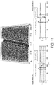
- valve port may be a valve port for a pneumatic force holding unit in a breath actuated metered dose inhaler, said valve port comprising a valve seal surface, which in use is engaged by a movable valve seal in a sealing arrangement, characterised in that the valve seal surface has a surface roughness average (RA) of 0.15 ⁇ m or less, preferably less than 0.12 ⁇ m, preferably from about 0.10 ⁇ m to about 0.01 ⁇ m.
- RA surface roughness average
- the valve seal comprises an elastomer, preferably a thermoplastic elastomer.
- the thermoplastic elastomer is selected from the group consisting of styrenic block copolymers, thermoplastic olefins, thermoplastic polyurethanes, thermoplastic copolyester, thermoplastic polyamide.
- thermoplastic elastomers can be injection moulded. Thermoplastic polyurethanes are particularly preferred.
- the elastomer may have a hardness of from about 80 to 90 Shore A.
- this elastomer has a hardness of from about 82 to 87 Shore A (e.g. BASF Elastollan ® 1185 A). Still more preferably, the elastomer has a hardness of about 85 Shore A.
- the elastomer may comprise a blend of thermoplastic polyurethane elastomer and at least one release agent, typically in an amount of from about 2 % to about 6 % by weight, for example, Elastollan Konz. 950/1 4% from BASF.
- valve seal when in a sealing arrangement, engages the valve seal surface with a moment of at least about 0.015 Nmm, preferably from about 0.017 Nmm to about 0.025 Nmm when in a rest configuration (e.g. with no vacuum), and from about 0.05 Nmm to about 0.11 Nmm when in a prepared configuration (e.g. with a vacuum).
- valve port may be manufacture using injection moulding; however, it will be appreciated that other methods may also be employed, e.g. spin casting, or an additive manufacturing technique: e.g. 3D printing.
- an improved seal is formed with a valve port seal during use.
- an improved seal significantly reduces the rate of degradation of the pressure difference within a pneumatic force holding unit in a prepared configuration, reducing the likelihood of accidental actuation and the breath actuated inhaler not delivering medicament upon inhalation: improving patient compliance and treatment outcomes.
- the breath actuated metered dose inhaler may comprise a flap valve for the canister fire system of a breath actuated metered dose inhaler, wherein the flap valve comprises a chassis for pivotal mounting within the inhaler, and the valve port seal is mounted on the chassis and configured to selectively engage the valve port in a sealing relation, and a vane for moving the valve port seal in direction away from the valve port in response to inhalation induced airflow.
- the breath actuated metered dose inhaler may comprise a diaphragm for the pneumatic force holding unit in the canister firing mechanism of the breath actuated metered dose inhaler comprising the valve port according to any previous aspect of the invention, or the flap valve according to the immediately preceding aspect.
- the diaphragm comprises a relatively rigid disk-like portion and relatively flexible membrane portion, and wherein the valve port is unitarily formed with the rigid disk-like portion.
- the relatively rigid disk-like portion, including the valve port, is typically made from a rigid material (relatively high stiffness) such as acrylonitrile butadiene styrene, which is particularly resistant to flexural deformation.
- the relatively flexible portion which may include a central portion, an annular flexure and a peripheral attachment ring may be moulded from an optimally flexible material (relatively low stiffness) such as a thermoplastic elastomer.
- a thermoplastic polyurethane is particularly preferred.
- the elastomer may have a hardness of from about 80 to 90 Shore A to about 35 to 40 Shore D.
- this elastomer has a hardness of from about 89 to about 90 Shore A and from about 37 to about 40 Shore D (e.g., BASF Elastollan ® 1185 A).
- the elastomer has a hardness of about 89 Shore A and about 37 Shore D.
- the elastomer comprises a blend of thermoplastic polyurethane elastomer and at least one release agent, typically in an amount of from about 2 % to about 6 % by weight, for example, Elastollan Konz. 950/1 4% from BASF.
- the invention further provides a breath actuated metered dose inhaler comprising a valve port, flap valve, and/or diaphragm.
- each of the valve ports disclosed may have a sealing surface with a surface roughness average (RA) of less than of less than 0.15 ⁇ m, preferably less than about 0.1 ⁇ m.
- RA surface roughness average
- the invention provides breath actuated metered dose inhalers.
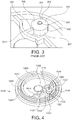
- Figures 8 shows a breath actuated inhaler which is merely an example of an inhaler in accordance with the present invention.
- the inhaler includes a force holding unit housing 12, a main body 14, a mouthpiece dust cap 16 and a dose counter door 18 having a dose counter window.
- the mouthpiece 66 may be replaced with a nose piece.
- a dose counter chamber 22 includes a dose counter system 24 closed within it by the dose counter door 18.
- the dose counter system includes an actuating pin 26 and return spring 28.
- the dose counter can take various forms and may, for example, be as described in EP2135199A or EP2514464A .
- the inhaler 10 includes a force holding unit 30 which includes: a filter 32, flap valve housing 34, flap valve 36, flap valve spring 38, compression spring 40, retaining ring 42, diaphragm 44 and lower cap 46.
- the inhaler also includes a canister 50 with a metering valve 52 and a valve stem 54; as well as a yoke 56 with drive rods or legs 58 having distal ends 59 which are driven by respective cams 60 on the pivotally-connected mouthpiece dust cap 16.
- the valve stem 54 may be fitted into an inner bore of a valve stem block which communicates with a nozzle (not shown) for ejection of inhalable substances through a central bore of a mouthpiece 66 ( Figure 8 ) of the main body 14 of the inhaler.
- the arrangement of openings in the metering valve of the present invention is similar to those described in US2016/0084385 .
- the metering valve of the present invention may be similar to the embodiment shown in FIG. 4 of US2016/0084385 , in which the valve body includes at least one first opening (i.e., at least one first side hole 100 that is arranged in a cylindrical portion of the valve body) and at least one second opening (i.e., at least one second side hole 111 that, as with the first hole(s), is arranged in a cylindrical portion of the valve body), the second opening(s) being axially offset relative to the first opening(s) along a longitudinal axis that extends between a first axial end and a second axial end of the valve body.
- the first opening(s) and second opening(s) that are axially offset from each other along the valve body enable the metering chamber to be filled and emptied.
- the force holding unit 30 operates substantially as disclosed with reference to Figures 1 to 3 of EP1289589A and the yoke 56 and mouthpiece dust cap 16 substantially as described in EP2514465A , including but not limited to Figure 22 thereof.
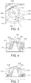
- FIG. 9 shows the flap valve 36 and diaphragm 44 in situ, in a patient inhalation configuration, so at the spring 38, the upper surface of the boss 80, and the valve orifice channel 78 are visible.
- the canister 50 is operable by a force holding unit 30 having a cap housing 12 attachable to a main body 14 of the inhaler.
- a mouthpiece cap 16 is opened to prime the inhaler ready for inhalation and then after inhalation the mouthpiece cap 16 is closed to reset the force holding unit 30, i.e. return it to a rest configuration.
- the geometry of the mechanism is arranged such that the balance occurs before the valve has been actuated.
- the force holding unit 30 relies on the described pressure difference to maintain the prepared configuration, and release thereof for firing the canister 50 under the action of the compression spring 40.
- the force holding unit 30 is therefore considered pneumatic within the normal meaning of the term.
- FIG. 4 a diaphragm 1000 according to the present invention for use with the medicament dispenser of FIGS. 8 and 9 is shown.
- the moulded flexible diaphragm 1000 includes a rigid disc-like section 1041, a flexible generally cylindrical wall section, or annular flexure 1045, and a thicker connector section, or peripheral attachment ring 1047.
- a central portion (not shown) is unitarily formed with and extends radially inwardly from the annular flexure 1045.
- the central portion preferably is provided in the form of a disk bonded along a top surface to a bottom surface of the rigid disc-like section 1041.
- the relatively thick disk-portion which includes the disc-like section 1041 of the diaphragm 1000, is moulded from acrylonitrile butadiene styrene, which is particularly resistant to flexural deformation.
- the relatively thin flexure portion which includes the central portion, the annular flexure 1045 and the peripheral attachment ring 1047, is moulded from thermoplastic polyurethane, permitting high performance flexibility.
- the multi-material diaphragm 1000 may be made using a multi-shot moulding process wherein the rigid disc-like section is moulded in a first step, and the second flexible portion is moulded in a second step, and at the same time bonded to the first portion.
- the rigid disc-like section 1041 defines a central upwardly extending boss 1002 for additional strength.
- the rigid disc-like section 1041 includes an outer axial wall 1004 which provides further strength to the diaphragm 1000.
- the valve port 1095 of the diaphragm 1000 passes through the rigid disc-like section 1041 and the central portion of the diaphragm.
- the valve port 1095 is closed by the valve port seal 76, which is biased closed by a flat spring 38, as shown in FIG. 9 .
- the rigid disc-like section 1041 of the diaphragm may include protrusions extending upwardly therefrom that receive the flat spring 38.
- the rigid disc-like section 1041 of the diaphragm 100 also includes a baffle 1014 on a top surface thereof for substantially preventing air flow between the valve port seal 76 and the diaphragm.
- the valve port 1095 comprises an annular boss 1100 projecting from an upper surface of the rigid disk-like portion 1041 of the diaphragm.
- the annular boss 1100 and rigid disk-like portion 1041 are a single unitary structure.
- the annular boss 1100 comprises a lower generally cylindrical body portion 1101 and an upper portion 1102 in the form of a truncated cone.
- the frustum of the truncated cone provides the upper surface 1103 of the annular boss 1100.
- the upper surface 1103 includes an annular projection 1104 which surrounds the entrance to the valve orifice channel and provides the sealing surface 1103, which in use engages the valve port seal in a sealing relation.
- annular boss 1100 Whilst the illustrated annular boss 1100, including both its upper 1102 and lower portions 1101, and the annular projection 1104, all have a circular circumference, it will be appreciated that other boss shapes may also be employed without departing from the invention. Accordingly, unless stated otherwise, for the purposes of the invention the use of annular, circumference, circumferential and/or radial, or the like, do not restrict the invention to circular cross-sectioned bodies. Equally, substantially circular cross-sectioned and/or circumferenced bodies are not excluded.
- the valve port 1095 further comprises two radially outwardly extending projections 1106 and 1107.
- a first projection 1106 extending from outer wall 1004 to the annular boss 1100.
- the second projection extending from the baffle 1014 to the annular boss 1100.
- the projections are of substantially the same thickness 'T'. In this illustrated embodiment 0.64 mm.
- the illustrated projections 1106 and 1107 are substantially uniformly circumferentially separated. That is to say, each and every projection is separated from its adjacent projections by substantially the same central angle.
- the illustrated projections 1106 and 1107 are separated from each other by a central angle of 180 degrees. They are diametrically opposed. As illustrated by reference to FIG 5 and FIG 6 , an imaginary straight-line Y running along a central axis of the projections passes through the central longitudinal axis X of the valve orifice channel. This arrangement concentrates polymer flow towards the centre of the boss 1100 during moulding, improving the surface finish of the upper surface 1103 and in particular its sealing surface 1105.
- the upper surfaces of the first 1107 and the second projections 1106 are both contiguous with the upper surface 1103 of the annular boss 1100.
- the upper surface 1110 of the first projection 1107 and the upper surface 1103 of the annular boss 1100 are at an angle (a) of greater than 90 degrees but less than 180 degrees.
- the upper surface 1109 of the second projection 1106 and the upper surface 1103 of the annular boss 1100 are at an angle ( ⁇ ) of approximately 180 degrees: preferably there is no discernible joint between the two.
- valve orifice channel 78 has a volume of 1.91 mm 3 and the annular boss 80 has a volume of 12.02 mm 3 .
- the annular boss 1100 is surrounded by a circumferential channel 1111 formed in the upper surface of the diaphragm 1041 surrounding the annular boss 1100.
- the channel 1111 has two sections 1112 and 1113 each extending between the two projections 1106 and 1107 around opposite sides of the annular boss 1100.
- the channel sections 1112 and 1113 reduce the depth of the relatively rigid disk-like portion 1041 of the diaphragm immediately adjacent to the annular boss; typically, to a depth 'D' less than the thickness 'T' of the projections 1106 and 1107. This arrangement concentrates polymer flow towards the centre of the annular boss 1100 during moulding, improving the smoothness of the upper surface 1103 and in particular the sealing surface 1105.
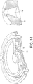
- FIG 10 shows an alternative diaphragm central disk 1041 according to the invention.
- this embodiment differs from that illustrated in FIG 4 in that one of the radially outwardly extending projections 1210 of the valve port 1095 extends from the annular boss 1100 to the central upwardly extending boss 1002.
- this arrangement concentrates polymer flow towards the centre of the annular boss 1100 during moulding, improving the smoothness of the upper surface 1003 and, in particular, the sealing surface 1005.
- injection moulded diaphragms according to the invention provide an increased yield during manufacturing compared to those illustrated in FIGS 1-3 and improved surface finish immediately adjacent the valve channel orifice.
- the yield has increased from about 50 % to about 85 %.
- the breath actuated metered dose inhaler comprises a reservoir, particularly a pressurized canister, comprising an active pharmaceutical ingredient (API).
- a reservoir particularly a pressurized canister, comprising an active pharmaceutical ingredient (API).
- API active pharmaceutical ingredient
- the active pharmaceutical ingredient is presented in a pharmaceutical composition
- a pharmaceutical composition comprising a propellant, optionally a co-solvent and optionally other pharmaceutically acceptable excipients.
- Preferred propellants include hydrofluroalkanes, in particular 1,1,1,2-tetrafluoroethane (HFA134a), 1,1,1,2,3,3,3-heptafluoropropane (HFA227), or combinations thereof. Most particular propellant is HFA134a. Most particular HFA134a concentration is from about 91.8 %w/w to 92.9 %w/w.
- HFA134a has a low boiling point (-26.1°C) and correspondingly high vapor pressure (572 kpa) at 20°C.
- co-solvents are selected from the list of aliphatic alcohols (particularly ethanol), glycerols and glycols. Most particular co-solvent is ethanol. Most particular ethanol concentration is about 8 %w/w.
- Ethanol is well known to be compatible with HFA-134a and increases the solubility of BDP.
- Ethanol anhydrous
- a concentration of around 8 %w/w of ethanol is known to provide necessary stability, preventing precipitation and achieving correct aerosol performance.
- compositions include surfactants, particularly oleic acid.
- the active pharmaceutical ingredient is suspended in the propellant.
- the active pharmaceutical ingredient is dissolved in the propellant.
- the active pharmaceutical ingredient may also be partly suspended and partly dissolved in the propellant.
- a particular active pharmaceutical ingredient is selected from the group consisting of anti-inflammatory agents, ⁇ 2-adrenoreceptor agonists, anti-cholinergic agents, anti-histamines, serotonin agonists, and combinations thereof.
- Suitable anti-inflammatory agents include corticosteroids and NSAIDs.
- Suitable corticosteroids which may be used include those oral and inhaled corticosteroids and their pro-drugs which have anti-inflammatory activity.
- suitable corticosteroids include methyl prednisolone, dexamethasone, fluticasone propionate, fluticasone furoate, beclomethasone, beclomethasone esters such as e.g. the 17-propionate ester or the 17,21-dipropionate ester, budesonide, flunisolide, mometasone, mometasone esters such as e.g. the furoate ester, triamcinolone acetonide, rofleponide, ciclesonide, and butixocort propionate.
- a particular corticosteroid is beclomethasone dipropionate (BDP).
- Suitable NSAIDs include sodium cromoglycate, nedocromil sodium, phosphodiesterase (PDE) inhibitors (e. g. theophylline, PDE4 inhibitors or mixed PDE3/PDE4 inhibitors), leukotriene antagonists, inhibitors of leukotriene synthesis, iNOS inhibitors, tryptase and elastase inhibitors, beta-2-integrin antagonists and adenosine receptor agonists or antagonists (e. g. adenosine 2a agonists), cytokine antagonists (e.g. chemokine antagonists) or inhibitors of cytokine synthesis.
- PDE phosphodiesterase
- Suitable ⁇ 2-adrenoreceptor agonists are selected from SABA (short-acting ⁇ 2-adrenoreceptor agonists), LABA (long-acting ⁇ 2-adrenoreceptor agonists), ultra-LABA (ultra-long-acting ⁇ 2-adrenoreceptor agonists), and combinations thereof.
- Suitable SABA include bitolterol, fenoterol, isoprenaline, orciprenaline, pirbuterol, procaterol, salbutamol, levosalbutamol, terbutaline, and pharmaceutically acceptable salts and esters thereof.
- Suitable LABA include bambuterol, clenbuterol, formoterol, arformoterol, protokylol, salmeterol, and pharmaceutically acceptable salts and esters thereof.
- Suitable ultra-LABA include indacaterol, olodaterol, vilanterol, and pharmaceutically acceptable salts and esters thereof.
- Particularly suitable ⁇ 2-adrenoreceptor agonists include salmeterol xinafoate, salbutamol sulphate, salbutamol free base, formoterol fumarate, fenoterol or terbutaline.
- a particular ⁇ 2-adrenoreceptor agonist is salbutamol sulphate.
- Suitable anticholinergic agents are those compounds that act as antagonists at the muscarinic receptor, in particular those compounds, which are antagonists of the M1 and M2 receptors.
- Compounds include the alkaloid of the belladonna plants as illustrated by the likes of atropine, scopolamine, homatropine, hyoscyamine; these compounds are normally administered as a salt, being tertiary amines.
- anticholinergics include ipratropium (e.g. as the bromide), oxitropium (e. g. as the bromide) and tiotropium (e. g. as the bromide).
- Further suitable anticholinergics of interest are methantheline, propantheline bromide, anisotropine methyl bromide, clidinium bromide, copyrrolate, isopropamide iodide, mepenzolate bromide, tridihexethyl chloride, hexocyclium, cyclopentolate hydrochloride, tropicamide, trihexyphenidyl hydrochloride, pirenzepine, telenzepine, and methoctramine.
- Suitable antihistamines include carbinoxamine maleat, clemastine fumarate, diphenylhydramine hydrochloride, dimenhydrinate, pyrilamine maleate, tripelennamine HCI, tripelennamine citrate, chlorpheniramine, chlorpheniramine maleate, acrivastine, hydroxyzine HCI, hydroxyzine pamoate, cyclizine HCI, cyclizine lactate, meclizine HCI, cetirizine HCI, astemizole, levocabastine HCI, loratadine, loratadine descarboethoxy analogue, terfenadine, fexofenadine hydrochloride, azelastine hydrochloride.
- the active pharmaceutical ingredient is selected from beclomethasone dipropionate (BDP), salbutamol sulphate and dihydroergotamine.
- the breath actuated metered dose inhaler comprises a pressurized canister comprising beclomethasone dipropionate as active pharmaceutical ingredient, HFA134a as propellant and ethanol as co-solvent.
- the breath actuated metered dose inhaler comprises a pressurized canister comprising beclomethasone dipropionate as active pharmaceutical ingredient at about 1.0 mg/ml, HFA134a as propellant at about 1090.20 mg/ml and ethanol as co-solvent at about 94.80 mg/ml.
- the breath actuated metered dose inhaler comprises a pressurized canister comprising beclomethasone dipropionate as active pharmaceutical ingredient at about 0.084 %w/w, HFA134a as propellant at about 91.9 %w/w and ethanol as co-solvent at about 8.0 %w/w.
- the breath actuated metered dose inhaler comprises a pressurized canister comprising beclomethasone dipropionate as active pharmaceutical ingredient at about 0.169 %w/w, HFA134a as propellant at about 91.8 %w/w and ethanol as co-solvent at about 8.0 %w/w.
- the breath actuated metered dose inhaler comprises a pressurized canister comprising salbutamol sulphate as active pharmaceutical ingredient, HFA134a as propellant and ethanol as co-solvent.
- the breath actuated metered dose inhaler comprises a pressurized canister comprising about 0.1098 mg of salbutamol sulphate as active pharmaceutical ingredient, about 27.8 mg of HFA134a as propellant and about 3.6 mg of ethanol as co-solvent.
- the diaphragms in both groups shared the following common features.
- the diaphragms of both groups were injection moulded on a Nestal 120 2-shot apparatus with 8+8 cavity mould and 25mm/25mm screw and barrel.
- the rigid disk-like portion was made from ABS Sabic CycolacTM HMG47MD, and the central portion, the annular flexure and the peripheral attachment ring were moulded from an elastomer comprising 96% BASF Elastollan ® 1185A with 4% BASF Konz 950/1 additive as release agent.
- the first "control” group diaphragms (M30579) were manufactured according to FIGS. 1 to 3 , with the injection moulding parameters as set out in Table 1.
- the second "test" group diaphragms (M24406) were manufactured according to FIG. 4 , with the injection moulding parameters as set out in Table 2.
- Table 1 Diaphragm - M24406 Parameter Process Value Minimum Value Maximum Value Injection Time .13 sec. .12 sec. .14 sec. Hold Pressure 750 bar 675 bar 825 bar Pack and Hold Time 1.0 sec. .9 sec. 1.1 sec. Cool Time 6.0 sec. 5.4 sec. 6.6 sec. Barrel Temp.
- the surface roughness of the sealing surface of each diaphragm was analysed using Bruker Contour GT white light interferometry machine at a magnification of 27.5x. Three areas of were scanned on each sealing surface, i.e. those indicated by the three-pronged arrow in Figure 13 . Each scanning area was 230 ⁇ m ⁇ 172 ⁇ m. The areas were selected so as to avoid any weld line.
- the step height measurement mode was used to measure the depth of the weld line of the diaphragm samples and the step width measurement mode and Cross Sectioning was used to measure the width of the weld line.
- the location of the measurements are indicated in Fig. 13 by rectangles 4 and 5: labelled 'Step Height Locations".
- the weld line (200) is indicated.
- Example results are illustrated in Fig. 11 and 12 , and summarised in Table 3.
- EasiBreathe TM force holding units were assembled comprising either the control or test diaphragms mentioned above.
- the ability of both types of FHU to retain a pressure difference after priming was then assessed using an Instron 5564 force testing unit according to the following method.
- the Instron was equipped with an Instron ⁇ 1kN load cell and operated using Bluehill 2.33.895 software.
- the FHU to be tested was secured in the Instron, with the Instron gripping the unit housing and the lower cap.
- the Instron was then used to compress the FHU until a force of 90N was achieved.
- the Instron was backed off 2.6 mm and a first, F1, force reading was recorded.
- the Instron was held in the same position for a period of 5 minutes, after which time a second force reading, F2, was taken.
- FHUs containing the test diaphragms according to the invention were able to maintain a pressure difference more effectively over the allotted time period.
Landscapes
- Health & Medical Sciences (AREA)
- Engineering & Computer Science (AREA)
- Life Sciences & Earth Sciences (AREA)
- General Health & Medical Sciences (AREA)
- Veterinary Medicine (AREA)
- Public Health (AREA)
- Animal Behavior & Ethology (AREA)
- Pulmonology (AREA)
- Heart & Thoracic Surgery (AREA)
- Bioinformatics & Cheminformatics (AREA)
- Anesthesiology (AREA)
- Biomedical Technology (AREA)
- Hematology (AREA)
- Pharmacology & Pharmacy (AREA)
- Medicinal Chemistry (AREA)
- Chemical & Material Sciences (AREA)
- Epidemiology (AREA)
- Emergency Medicine (AREA)
- General Chemical & Material Sciences (AREA)
- Chemical Kinetics & Catalysis (AREA)
- Nuclear Medicine, Radiotherapy & Molecular Imaging (AREA)
- Organic Chemistry (AREA)
- Biophysics (AREA)
- Otolaryngology (AREA)
- Containers And Packaging Bodies Having A Special Means To Remove Contents (AREA)
- Nozzles (AREA)
- Acyclic And Carbocyclic Compounds In Medicinal Compositions (AREA)
- Pipe Accessories (AREA)
- Check Valves (AREA)
- Pharmaceuticals Containing Other Organic And Inorganic Compounds (AREA)
- Lift Valve (AREA)
- Medicinal Preparation (AREA)
Description
- The present invention relates to a metered dose inhaler and, in particular, a breath actuated metered dose inhaler. The invention further provides valve port and a diaphragm for a pneumatic force holding unit of a breath actuated metered dose inhaler, and a flap valve for the canister fire system of a breath actuated metered dose inhaler.
- Inhalers for delivering medicament to a patient by inhalation are known. Such devices include metered dose inhalers (of both pressurised and dry-powder types). Metered dose inhalers typically comprise a medicament-containing vessel and an actuator housing having a medicament delivery outlet in the form of a mouthpiece or nosepiece.
- The medicament-containing vessel may be a pressurized canister containing a mixture of active medicament and propellant. Such canisters are usually formed from a deep-drawn aluminium cup having a crimped lid which carries a metering valve assembly. The metering valve assembly is provided with a protruding valve stem which, in use, is inserted as a tight push fit into a stem block in the actuator housing.
- Metered-dose inhalers may either be of the manually operable type or the breath actuated type. For the manually operable type, the patient self- administers the medicament by manually pressing the closed end of the canister into the actuator housing to cause movement of the canister relative to its valve stem (which is fixed in the stem block of the actuator housing). This movement is sufficient to actuate the metering valve assembly of the canister, resulting in the pressurised contents of a metering chamber being vented through the stem, through the stem block and its exit orifice, and causing the medicament to exit the mouthpiece or nosepiece as an aerosol mist. Simultaneously with this action, the patient inhales through the nosepiece or mouthpiece, entraining the aerosol mist in the inhaled stream of air. The patient then releases the depression force on the canister which, under the action of an internal valve spring, moves upward with respect to the valve stem, returning to its resting position.
- A more recent development is the so-called breath actuated metered-dose inhaler, which serves to automatically displace the canister relative to its valve stem and release the contents of the canister's metering chamber in response to a patient's inhalation. The general purpose of such inhalers is to alleviate difficulties in coordinating actuation of the metering valve assembly with the patient's inhalation, and to provide for a maximal amount of medication to be drawn into the patient's lungs.
- A known breath actuated inhaler, disclosed in
WO9209323A1 WO0193933A2 - The force holding unit comprises a compression spring, a lower cap that engages the canister, a diaphragm attached to an upper surface of the lower cap, and a pivotally mounted flap valve for selectively sealing a valve port located in the diaphragm.
- In use, when the mouthpiece cap is opened, the lower cap is forced downwards under the action of the compression spring. Then, as the lower cap moves down, an enclosed volume between the diaphragm and the lower cap is increased by a linear amount, and whilst valve port remains closed, this creates a pressure difference in the enclosed volume.
- The offset of the differential between the pressure in the enclosed volume and atmospheric pressure results in the lower cap resisting action of the compression spring. Downward movement of the lower cap continues until the force is balanced between the force of the compression spring and the opposing forces of the pressure difference and metering valve. This is a prepared configuration.
- The geometry of the mechanism is arranged such that the balance occurs before the valve has been actuated.
- Flow of air across a vane on the flap valve during inhalation causes the valve to pivot, moving the flap valve seal out of its rest position, and opening a valve channel in the diaphragm. The subsequent passage of air into the volume between the diaphragm and the lower cap allows the volume to reach atmospheric pressure. The resulting imbalance of forces acting on the lower cap and canister produces the downward motion of the canister and actuation of the aerosol metering valve: releasing a measured dose through the dispensing nozzle and into the mouthpiece.
- Referring to
FIGS. 1 and 2 a knowndiaphragm assembly 640 for use with a breath actuated inhaler is shown. - The moulded
flexible diaphragm 640 includes a rigid disc-like section 641, a flexible generally cylindrical wall section, orannular flexure 645, and a thicker connector section, orperipheral attachment ring 647. A central portion is unitarily formed with and extends radially inwardly from theannular flexure 645. The central portion is provided in the form of a disk bonded along a top surface to a bottom surface of the rigid disc-like section 641, i. e., surfaces substantially transverse to the central axis of thediaphragm 640. - The relatively thick disk-portion is moulded from a rigid material (relatively high stiffness) such as acrylonitrile butadiene styrene (ABS), which is particularly resistant to flexural deformation.
- The relatively thin flexure portion which includes the central portion, the
annular flexure 645 and theperipheral attachment ring 647, is moulded from an optimally flexible material (relatively low stiffness) such as a thermoplastic elastomer (TPE), permitting high performance. Themulti-material diaphragm 640 may be manufactured using a multi-shot moulding process. - As shown in
FIGS. 1 and 2 , the central portion and the rigid disc-like section 641 both define a central upwardly extendingboss 702 for additional strength. In addition, the rigid disc-like section 641 includes an outeraxial wall 704 which provides further strength to thediaphragm 640. The central portion includes axial walls which are received within and bonded to axial grooves of the rigid disc-like section 641, thereby providing bonding surfaces substantially parallel with the central axis of thediaphragm 640 and increasing the total bonding surface area between the central portion and the rigid disc-like section 641. - In use, the
peripheral attachment ring 647 of thediaphragm 640 is fitted around an annular wall of the lower cap and is secured in an air-tight manner thereon with a retainer ring by snap-fitting. The retainer ring also provides a snug fit for one end of the compression spring, such that the compression spring is thus located and free to act on the sleeve. - The
valve channel 690 of thediaphragm 640 passes through the rigid disc-like section 641 and the central portion of the diaphragm. Thevalve channel 690 is closed by a valve seal (not shown), which is biased closed by a flat spring. The rigid disc-like section 641 of the diaphragm includesprotrusions 712 extending upwardly therefrom that receive and correctly position a flat spring. The rigid disc-like section 641 of thediaphragm 640 also includes abaffle 714 on a top surface thereof for substantially preventing air flow between the valve seal and the diaphragm. - The rigid disc-
like section 641 of thediaphragm 640 additionally includes anassembly location key 716 for use in correctly assembling thediaphragm 640 within the actuator assembly. - As better illustrated in
FIG. 3 , avalve port 301 comprising anannular boss 302 defines thevalve orifice channel 690. Theboss 302 comprises two radially outwardly extendingprojections boss 302 during injection moulding. Theboss 302 comprises acircumferential side wall 307, a radially extendingupper surface 308, including asealing surface 309. The radially outwardly extendingprojections upper surfaces vertical side wall 307 of theboss 302. - An inhaler according to the features of the preamble of claim 1 is known from document
GB2263873A - When using inhalers similar to those discussed above, it was observed that on occasion patients may not receive a measured dose upon inhalation, i.e. the canister does not fire.
- Following these observations, an investigation by the inventors found that the missed dose of medicament may be because of unintentional actuation of the inhaler. The investigation found that the unintentional actuation may occur because of unintentional misuse leading to accidental actuation, said misuse including failing to use the inhaler immediately after priming.
- More specifically, the inventors found that when in the prepared position the pressure difference maintained by the force holding degraded over a relatively short period of time, allowing the lower cap to progress in a canister fire direction under the action of the compression spring. This progression may continue until the canister fires.
- Once the canister has fired accidentally as a result of the degradation of the pressure difference maintained by the force holding unit, the inhaler will not fire upon subsequent inhalation and the patient will not receive the intended dose of medicament.
- The present invention aims to alleviate at least to a certain extent at least one of the problems of the prior art.
- Accordingly, in a first aspect the invention provides a breath-actuated metered dose inhaler according to claim 1. Preferred embodiments are matter of the dependent claims.
- In embodiments, the valve port may be an injection moulded polymer valve port for a pneumatic force holding unit in a breath actuated metered dose inhaler. The valve port comprising an annular boss defining a valve orifice channel. The valve port further comprising two, three, four or more, radially outwardly extending projections defining a path through which polymer passed to form the boss during moulding. The radially outwardly extending projections being substantially uniformly circumferentially separated. Typically extending from a circumferential outer wall of the annular boss. Preferably, their circumferential uniformity is offset by less than about 5 degrees, preferably by less than about 2 degrees. Typically, the boss has a longitudinal axis which passes through the valve orifice port, and two radially extending projections and the valve orifice port may lie in a common plane coincident with the longitudinal axis. In a preferred arrangement, the boss comprises two circumferentially uniformly separated radially outwardly extending projections, i.e. with a central angle of 180 degrees +/- 5 degrees.
- It has been found that by providing a boss with radially outwardly extending projections as described, the surface finish of the valve port, in particular, immediately adjacent the valve orifice is significantly improved, allowing a better seal to be formed with a valve port seal during use. The improved seal significantly reduces the rate of degradation of the pressure difference within a pneumatic force holding unit in a prepared configuration, reducing the likelihood of accidental actuation and the breath actuated inhaler not delivering medicament upon inhalation: improving patient compliance and treatment outcomes.
- In embodiments, the valve port may be an injection moulded polymer valve port for a pneumatic force holding unit in a breath actuated metered dose inhaler. The valve port comprises an annular boss defining a valve orifice channel. The valve port comprising one, two, or more radially outwardly extending projections defining a path through which polymer passed to form the boss during moulding, wherein an upper surface of the one or more radially outwardly extending projections and an upper surface of the annular boss are contiguous. Preferably, the upper surface of the annular boss and the upper surface of the projection are at an angle between about 90 degrees and about 180 degrees, preferably an obtuse angle, more preferably between 120 degrees and 180 degrees.
- Advantageously, it has been found that because the upper surfaces are contiguous during moulding molten polymer flows along a mould path defining the projections and does no stall as it enters the chamber defining the boss. By way of comparison, during moulding of the boss illustrated in
FIG. 3 , the molten polymer must travel vertically along an outer side surface of the boss from the upper surface of the projections to the boss' upper surface, stalling radial flow. Valve ports of the inventive arrangement have been found to have a surface finish that is significantly improved, in particular immediately adjacent the valve orifice. This facilitates a better sealing with a valve port seal during use. The improved seal significantly reduces the rate of degradation of the pressure difference within a pneumatic force holding unit in breath actuated inhaler in a prepared configuration, reducing the likelihood of accidental actuation and the breath actuated inhaler not delivering medicament upon inhalation: improving patient compliance and treatment outcomes. - In embodiments the valve port may be an injection moulded polymer valve port for a pneumatic force holding unit in a breath actuated metered dose inhaler, said valve port being located on a planar body and comprising an annular boss defining a valve orifice channel. The valve port further comprising one or more radially outwardly extending projections defining a path through which polymer passed to form the boss during moulding. A portion of the planar body immediately adjacent the boss has a depth that is less than or equal to a minimum thickness of the radially outwardly extending projection. Typically, the ratio of the depth of the portion immediately adjacent to the boss to the minimum thickness of the radially outwardly extending projection is from about 1:1 to about 1:2, preferably from about 1:1 to about 3:4. Typically, the portion of the planar body immediately adjacent the boss circumferentially encloses, preferably fully encloses, the boss between the one or more radially extending projections.
- Typically, the portion of the planar body immediately adjacent the boss has a depth of from about 0.50 mm to about 0.70 mm, preferably from about 0.55 mm to about 0.65 mm. 0.60 mm is an example. The planar body is typically the relatively rigid disk-like portion of the diaphragm.
- Additionally, or alternatively, the radially outwardly extending projections may have a thickness of from about 0.54 mm to about 0.83 mm, preferably from about 0.64 mm to about 0.73 mm. 0.68 mm is an example. Where there are two or more radially outwardly extending projections, typically they each have substantially the same thickness. The radially outwardly extending projections are typically drafted to aid mould release. In this instance the thickness relates to the minimum thickness of the projection.
- Advantageously, it has been found that a boss that is surrounded by a narrowing (e.g. a narrowed portion of the planar body) concentrates polymer flow towards the upper surface of the boss during moulding. This has the effect of improving the surface finish of the valve port immediately adjacent the valve orifice, allowing a better seal to be formed with a valve port seal during use. The improved seal significantly reduces the rate of degradation of the pressure difference within a pneumatic force holding unit in a breath actuated inhaler in a prepared configuration, reducing the likelihood of accidental actuation and the breath actuated inhaler not delivering medicament upon inhalation: improving patient compliance and treatment outcomes.
- In embodiments the valve port may be a valve port for a pneumatic force holding unit in a breath actuated metered dose inhaler, said valve port comprising an annular boss with an inner wall defining a valve orifice channel wherein the volume of the orifice channel defined by the inner wall of the boss is greater than about 12.7 % of the volume of the boss, preferably from about 12.7 % to about 20 %, more preferably from about 13 % to about 17 %, 15.5 % being an example, and/or wherein the inner wall defines a frustum of an imaginary cone with an apex angle of greater than about 20 degrees, preferably from about 22 degrees to about 35 degrees, more preferably from about 24 degrees to about 30 degrees. 28 degrees being an example.
- Typically, the valve orifice channel has a cross-sectional area at its uppermost (i.e. sealing) end of from about 0.22 mm2 to about 0.31 mm2, 0.26 mm2 being an example. Typically, the valve orifice channel has a substantially circular cross-section, typically along its entire length. Preferably, a portion of the wall of the valve orifice channel defines the frustum of an imaginary cone.
- It has been found that by providing a boss with a high valve orifice channel volume to boss volume ratio, during injection moulding, polymer flow is concentrated towards the upper surface of the boss. Likewise, when the inner surface of the valve orifice defines the frustum of an imaginary cone with an apex of greater than 20 degrees. This has the effect of improving the surface finish of the valve port immediately adjacent the valve orifice channel opening, allowing a better seal to be formed with a valve port seal during use. As in other aspects, the improved seal significantly reduces the rate of degradation of the pressure difference within a pneumatic force holding unit of an inhaler in a prepared configuration, reducing the likelihood of accidental actuation and the breath actuated inhaler not delivering medicament upon inhalation: improving patient compliance and treatment outcomes.
- In embodiment the valve port may be a valve port for a pneumatic force holding unit in a breath actuated metered dose inhaler, said valve port comprising a valve seal surface, which in use is engaged by a movable valve seal in a sealing arrangement, characterised in that the valve seal surface has a surface roughness average (RA) of 0.15 µm or less, preferably less than 0.12 µm, preferably from about 0.10 µm to about 0.01 µm.
- Typically, the valve seal comprises an elastomer, preferably a thermoplastic elastomer. Preferably the thermoplastic elastomer is selected from the group consisting of styrenic block copolymers, thermoplastic olefins, thermoplastic polyurethanes, thermoplastic copolyester, thermoplastic polyamide. Advantageously thermoplastic elastomers can be injection moulded. Thermoplastic polyurethanes are particularly preferred.
- The elastomer may have a hardness of from about 80 to 90 Shore A. Preferably this elastomer has a hardness of from about 82 to 87 Shore A (e.g. BASF Elastollan® 1185 A). Still more preferably, the elastomer has a hardness of about 85 Shore A.
- In embodiments, the elastomer may comprise a blend of thermoplastic polyurethane elastomer and at least one release agent, typically in an amount of from about 2 % to about 6 % by weight, for example, Elastollan Konz. 950/1 4% from BASF.
- Preferably the valve seal, when in a sealing arrangement, engages the valve seal surface with a moment of at least about 0.015 Nmm, preferably from about 0.017 Nmm to about 0.025 Nmm when in a rest configuration (e.g. with no vacuum), and from about 0.05 Nmm to about 0.11 Nmm when in a prepared configuration (e.g. with a vacuum).
- The valve port may be manufacture using injection moulding; however, it will be appreciated that other methods may also be employed, e.g. spin casting, or an additive manufacturing technique: e.g. 3D printing.
- By reducing the surface roughness of the valve port immediately adjacent the valve orifice an improved seal is formed with a valve port seal during use. As in other aspects, an improved seal significantly reduces the rate of degradation of the pressure difference within a pneumatic force holding unit in a prepared configuration, reducing the likelihood of accidental actuation and the breath actuated inhaler not delivering medicament upon inhalation: improving patient compliance and treatment outcomes.
- In embodiments, the breath actuated metered dose inhaler may comprise a flap valve for the canister fire system of a breath actuated metered dose inhaler, wherein the flap valve comprises a chassis for pivotal mounting within the inhaler, and the valve port seal is mounted on the chassis and configured to selectively engage the valve port in a sealing relation, and a vane for moving the valve port seal in direction away from the valve port in response to inhalation induced airflow.
- In embodiments, the breath actuated metered dose inhaler may comprise a diaphragm for the pneumatic force holding unit in the canister firing mechanism of the breath actuated metered dose inhaler comprising the valve port according to any previous aspect of the invention, or the flap valve according to the immediately preceding aspect. Typically, the diaphragm comprises a relatively rigid disk-like portion and relatively flexible membrane portion, and wherein the valve port is unitarily formed with the rigid disk-like portion.
- The relatively rigid disk-like portion, including the valve port, is typically made from a rigid material (relatively high stiffness) such as acrylonitrile butadiene styrene, which is particularly resistant to flexural deformation. The relatively flexible portion which may include a central portion, an annular flexure and a peripheral attachment ring may be moulded from an optimally flexible material (relatively low stiffness) such as a thermoplastic elastomer. A thermoplastic polyurethane is particularly preferred.
- The elastomer may have a hardness of from about 80 to 90 Shore A to about 35 to 40 Shore D. Preferably this elastomer has a hardness of from about 89 to about 90 Shore A and from about 37 to about 40 Shore D (e.g., BASF Elastollan® 1185 A). Still more preferably, the elastomer has a hardness of about 89 Shore A and about 37 Shore D.
- Additionally, the elastomer comprises a blend of thermoplastic polyurethane elastomer and at least one release agent, typically in an amount of from about 2 % to about 6 % by weight, for example, Elastollan Konz. 950/1 4% from BASF.
- The invention further provides a breath actuated metered dose inhaler comprising a valve port, flap valve, and/or diaphragm.
- It will be appreciated that all of the aspects and embodiments herein described may be combined mutatis mutandis. Specifically, each of the valve ports disclosed may have a sealing surface with a surface roughness average (RA) of less than of less than 0.15 µm, preferably less than about 0.1 µm.
- Preferred features of the present invention will now be described, by way of example, with reference to the accompanying drawings, in which:
-
Fig. 1-3 show a known multi-material diaphragm for a breath actuated inhaler; -
Fig. 4 shows a multi-material diaphragm according to the invention; -
Fig. 5-7 show cross-sections of a valve port according to the invention; -
Fig. 8-9 shows a breath actuated metered dose inhaler according to the invention; -
Fig. 10 shows an alternative diaphragm according to the invention; -
Fig. 11 shows surface roughness testing results of a known valve port sealing surface; -
Fig. 12 shows surface roughness testing results of a valve port sealing surface according to the invention. -
Fig. 13 shows the locations at which surface roughness measurements may be taken. -
Fig. 14 shows the volume of the boss and the valve orifice channel. - The invention provides breath actuated metered dose inhalers.
-
Figures 8 shows a breath actuated inhaler which is merely an example of an inhaler in accordance with the present invention. The inhaler includes a force holdingunit housing 12, amain body 14, amouthpiece dust cap 16 and adose counter door 18 having a dose counter window. In other embodiments comprising nasal inhalers, themouthpiece 66 may be replaced with a nose piece. - As shown by the exploded view of
Figure 8 , adose counter chamber 22 includes adose counter system 24 closed within it by thedose counter door 18. The dose counter system includes anactuating pin 26 and returnspring 28. The dose counter can take various forms and may, for example, be as described inEP2135199A orEP2514464A . - As also shown in
Figure 8 , theinhaler 10 includes aforce holding unit 30 which includes: afilter 32,flap valve housing 34,flap valve 36,flap valve spring 38,compression spring 40, retainingring 42, diaphragm 44 andlower cap 46. The inhaler also includes acanister 50 with ametering valve 52 and avalve stem 54; as well as ayoke 56 with drive rods orlegs 58 having distal ends 59 which are driven byrespective cams 60 on the pivotally-connectedmouthpiece dust cap 16. The valve stem 54 may be fitted into an inner bore of a valve stem block which communicates with a nozzle (not shown) for ejection of inhalable substances through a central bore of a mouthpiece 66 (Figure 8 ) of themain body 14 of the inhaler. - In embodiments, the arrangement of openings in the metering valve of the present invention is similar to those described in
US2016/0084385 . In particular, the metering valve of the present invention may be similar to the embodiment shown inFIG. 4 ofUS2016/0084385 , in which the valve body includes at least one first opening (i.e., at least onefirst side hole 100 that is arranged in a cylindrical portion of the valve body) and at least one second opening (i.e., at least one second side hole 111 that, as with the first hole(s), is arranged in a cylindrical portion of the valve body), the second opening(s) being axially offset relative to the first opening(s) along a longitudinal axis that extends between a first axial end and a second axial end of the valve body. The first opening(s) and second opening(s) that are axially offset from each other along the valve body enable the metering chamber to be filled and emptied. - The
force holding unit 30 operates substantially as disclosed with reference toFigures 1 to 3 ofEP1289589A and theyoke 56 andmouthpiece dust cap 16 substantially as described inEP2514465A , including but not limited to Figure 22 thereof. -
FIG. 9 shows theflap valve 36 and diaphragm 44 in situ, in a patient inhalation configuration, so at thespring 38, the upper surface of theboss 80, and thevalve orifice channel 78 are visible. - The
canister 50 is operable by aforce holding unit 30 having acap housing 12 attachable to amain body 14 of the inhaler. In use, amouthpiece cap 16 is opened to prime the inhaler ready for inhalation and then after inhalation themouthpiece cap 16 is closed to reset theforce holding unit 30, i.e. return it to a rest configuration. - In more detail, when the
mouthpiece cap 16 is opened, thelower cap 46 is forced downwards under the action of thecompression spring 40. Then, as thelower cap 46 moves down, an enclosed volume between the diaphragm 44 and thelower cap 46 is increased by a linear amount, and whilst valve port remains closed, this creates a pressure difference in the enclosed volume. - The offset of the differential between the pressure in the enclosed volume and atmospheric pressure results in the
lower cap 46 resisting action of thecompression spring 40. Downward movement of thelower cap 46 continues until the force is balanced between the force of thecompression spring 46 and the opposing forces of the pressure difference andmetering valve 52. - The geometry of the mechanism is arranged such that the balance occurs before the valve has been actuated.
- Upon inhalation, air enters the inhaler through approximately ten
air inlets 72 formed on thecap housing 12. Flow of air across avane 74 on theflap valve 36 during inhalation causes thevalve 36 to pivot, moving theflap valve seal 76 out of its rest position, and opening avalve orifice channel 78 in the diaphragm 44. The subsequent passage of air into the volume between the diaphragm 44 and thelower cap 46 allows the volume to reach atmospheric pressure. The resulting imbalance of forces acting on thelower cap 46 andcanister 50 produces the downward (forward) motion of thecanister 50 and actuation of the aerosol metering valve 52: releasing a measured dose through the dispensing nozzle and into themouthpiece 66. - The
force holding unit 30 relies on the described pressure difference to maintain the prepared configuration, and release thereof for firing thecanister 50 under the action of thecompression spring 40. Theforce holding unit 30 is therefore considered pneumatic within the normal meaning of the term. - Referring to
FIG. 4 , adiaphragm 1000 according to the present invention for use with the medicament dispenser ofFIGS. 8 and9 is shown. - The moulded
flexible diaphragm 1000 includes a rigid disc-like section 1041, a flexible generally cylindrical wall section, orannular flexure 1045, and a thicker connector section, orperipheral attachment ring 1047. A central portion (not shown) is unitarily formed with and extends radially inwardly from theannular flexure 1045. The central portion preferably is provided in the form of a disk bonded along a top surface to a bottom surface of the rigid disc-like section 1041. - The relatively thick disk-portion which includes the disc-
like section 1041 of thediaphragm 1000, is moulded from acrylonitrile butadiene styrene, which is particularly resistant to flexural deformation. The relatively thin flexure portion which includes the central portion, theannular flexure 1045 and theperipheral attachment ring 1047, is moulded from thermoplastic polyurethane, permitting high performance flexibility. Themulti-material diaphragm 1000 may be made using a multi-shot moulding process wherein the rigid disc-like section is moulded in a first step, and the second flexible portion is moulded in a second step, and at the same time bonded to the first portion. - As shown in
FIG. 4 , the rigid disc-like section 1041 defines a central upwardly extendingboss 1002 for additional strength. In addition, the rigid disc-like section 1041 includes an outeraxial wall 1004 which provides further strength to thediaphragm 1000. - The
valve port 1095 of thediaphragm 1000 passes through the rigid disc-like section 1041 and the central portion of the diaphragm. Thevalve port 1095 is closed by thevalve port seal 76, which is biased closed by aflat spring 38, as shown inFIG. 9 . Although not shown, the rigid disc-like section 1041 of the diaphragm may include protrusions extending upwardly therefrom that receive theflat spring 38. The rigid disc-like section 1041 of thediaphragm 100 also includes abaffle 1014 on a top surface thereof for substantially preventing air flow between thevalve port seal 76 and the diaphragm. - As illustrated in
FIG. 4 thevalve port 1095 comprises anannular boss 1100 projecting from an upper surface of the rigid disk-like portion 1041 of the diaphragm. Typically, theannular boss 1100 and rigid disk-like portion 1041 are a single unitary structure. Theannular boss 1100 comprises a lower generallycylindrical body portion 1101 and anupper portion 1102 in the form of a truncated cone. The frustum of the truncated cone provides theupper surface 1103 of theannular boss 1100. Theupper surface 1103 includes anannular projection 1104 which surrounds the entrance to the valve orifice channel and provides thesealing surface 1103, which in use engages the valve port seal in a sealing relation. Whilst the illustratedannular boss 1100, including both its upper 1102 andlower portions 1101, and theannular projection 1104, all have a circular circumference, it will be appreciated that other boss shapes may also be employed without departing from the invention. Accordingly, unless stated otherwise, for the purposes of the invention the use of annular, circumference, circumferential and/or radial, or the like, do not restrict the invention to circular cross-sectioned bodies. Equally, substantially circular cross-sectioned and/or circumferenced bodies are not excluded. - As illustrated, the
valve port 1095 further comprises two radially outwardly extendingprojections first projection 1106 extending fromouter wall 1004 to theannular boss 1100. The second projection extending from thebaffle 1014 to theannular boss 1100. During moulding molten polymer, or prepolymer, flows along a path defined by the mould corresponding to each of the twoprojections 1106 1107 into the annular boss mould cavity. Typically, the projections are of substantially the same thickness 'T'. In this illustrated embodiment 0.64 mm. The illustratedprojections projections FIG 5 and FIG 6 , an imaginary straight-line Y running along a central axis of the projections passes through the central longitudinal axis X of the valve orifice channel. This arrangement concentrates polymer flow towards the centre of theboss 1100 during moulding, improving the surface finish of theupper surface 1103 and in particular itssealing surface 1105. - As better illustrated in
FIG. 6 , the upper surfaces of the first 1107 and thesecond projections 1106 are both contiguous with theupper surface 1103 of theannular boss 1100. Theupper surface 1110 of thefirst projection 1107 and theupper surface 1103 of theannular boss 1100 are at an angle (a) of greater than 90 degrees but less than 180 degrees. Theupper surface 1109 of thesecond projection 1106 and theupper surface 1103 of theannular boss 1100 are at an angle (β) of approximately 180 degrees: preferably there is no discernible joint between the two. - As a result of each of the
upper surfaces projections 1106 1107 and theupper surface 1103 of theannular boss 1100 joining directly, during moulding, molten polymer is able to flow directly along the mould surface from projection upper surface to boss upper surface without stalling, improving the finish of theupper surface 1103 of theannular boss 1100 and in particular the sealingsurface 1105. - As illustrated in
FIG 6 a portion of the valve orifice channel forms the frustum of an imaginary cone with an apex angle θ of 28 degrees. With reference toFig. 14 , thevalve orifice channel 78 has a volume of 1.91 mm3 and theannular boss 80 has a volume of 12.02 mm3. - As better illustrated in
FIGS 5 and 7 , theannular boss 1100 is surrounded by acircumferential channel 1111 formed in the upper surface of thediaphragm 1041 surrounding theannular boss 1100. Thechannel 1111 has twosections projections annular boss 1100. Thechannel sections like portion 1041 of the diaphragm immediately adjacent to the annular boss; typically, to a depth 'D' less than the thickness 'T' of theprojections annular boss 1100 during moulding, improving the smoothness of theupper surface 1103 and in particular the sealingsurface 1105. -
FIG 10 shows an alternative diaphragmcentral disk 1041 according to the invention. As illustrated, this embodiment differs from that illustrated inFIG 4 in that one of the radially outwardly extendingprojections 1210 of thevalve port 1095 extends from theannular boss 1100 to the central upwardly extendingboss 1002. As with thevalve port 1095 shown inFIG 4 , this arrangement concentrates polymer flow towards the centre of theannular boss 1100 during moulding, improving the smoothness of theupper surface 1003 and, in particular, the sealingsurface 1005. - Advantageously, it has been found that injection moulded diaphragms according to the invention provide an increased yield during manufacturing compared to those illustrated in
FIGS 1-3 and improved surface finish immediately adjacent the valve channel orifice. In embodiments, the yield has increased from about 50 % to about 85 %. - In embodiments the breath actuated metered dose inhaler comprises a reservoir, particularly a pressurized canister, comprising an active pharmaceutical ingredient (API).
- Preferably the active pharmaceutical ingredient is presented in a pharmaceutical composition comprising a propellant, optionally a co-solvent and optionally other pharmaceutically acceptable excipients.
- Preferred propellants include hydrofluroalkanes, in particular 1,1,1,2-tetrafluoroethane (HFA134a), 1,1,1,2,3,3,3-heptafluoropropane (HFA227), or combinations thereof. Most particular propellant is HFA134a. Most particular HFA134a concentration is from about 91.8 %w/w to 92.9 %w/w.
- HFA134a has a low boiling point (-26.1°C) and correspondingly high vapor pressure (572 kpa) at 20°C.
- Particular co-solvents are selected from the list of aliphatic alcohols (particularly ethanol), glycerols and glycols. Most particular co-solvent is ethanol. Most particular ethanol concentration is about 8 %w/w.
- Ethanol is well known to be compatible with HFA-134a and increases the solubility of BDP. Ethanol (anhydrous) is used as a co-solvent to aid solubility of BDP in HFA134a. A concentration of around 8 %w/w of ethanol is known to provide necessary stability, preventing precipitation and achieving correct aerosol performance.
- Other pharmaceutically acceptable excipients include surfactants, particularly oleic acid.
- Preferably, the active pharmaceutical ingredient is suspended in the propellant. Alternatively, the active pharmaceutical ingredient is dissolved in the propellant. The active pharmaceutical ingredient may also be partly suspended and partly dissolved in the propellant.
- A particular active pharmaceutical ingredient is selected from the group consisting of anti-inflammatory agents, β2-adrenoreceptor agonists, anti-cholinergic agents, anti-histamines, serotonin agonists, and combinations thereof.
- Suitable anti-inflammatory agents include corticosteroids and NSAIDs.
- Suitable corticosteroids which may be used include those oral and inhaled corticosteroids and their pro-drugs which have anti-inflammatory activity. Examples of suitable corticosteroids include methyl prednisolone, dexamethasone, fluticasone propionate, fluticasone furoate, beclomethasone, beclomethasone esters such as e.g. the 17-propionate ester or the 17,21-dipropionate ester, budesonide, flunisolide, mometasone, mometasone esters such as e.g. the furoate ester, triamcinolone acetonide, rofleponide, ciclesonide, and butixocort propionate.
- A particular corticosteroid is beclomethasone dipropionate (BDP).
- Suitable NSAIDs include sodium cromoglycate, nedocromil sodium, phosphodiesterase (PDE) inhibitors (e. g. theophylline, PDE4 inhibitors or mixed PDE3/PDE4 inhibitors), leukotriene antagonists, inhibitors of leukotriene synthesis, iNOS inhibitors, tryptase and elastase inhibitors, beta-2-integrin antagonists and adenosine receptor agonists or antagonists (e. g. adenosine 2a agonists), cytokine antagonists (e.g. chemokine antagonists) or inhibitors of cytokine synthesis.
- Suitable β2-adrenoreceptor agonists are selected from SABA (short-acting β2-adrenoreceptor agonists), LABA (long-acting β2-adrenoreceptor agonists), ultra-LABA (ultra-long-acting β2-adrenoreceptor agonists), and combinations thereof.
- Suitable SABA include bitolterol, fenoterol, isoprenaline, orciprenaline, pirbuterol, procaterol, salbutamol, levosalbutamol, terbutaline, and pharmaceutically acceptable salts and esters thereof.
- Suitable LABA include bambuterol, clenbuterol, formoterol, arformoterol, protokylol, salmeterol, and pharmaceutically acceptable salts and esters thereof.
- Suitable ultra-LABA include indacaterol, olodaterol, vilanterol, and pharmaceutically acceptable salts and esters thereof.
- Particularly suitable β2-adrenoreceptor agonists include salmeterol xinafoate, salbutamol sulphate, salbutamol free base, formoterol fumarate, fenoterol or terbutaline.
- A particular β2-adrenoreceptor agonist is salbutamol sulphate.
- Suitable anticholinergic agents are those compounds that act as antagonists at the muscarinic receptor, in particular those compounds, which are antagonists of the M1 and M2 receptors. Compounds include the alkaloid of the belladonna plants as illustrated by the likes of atropine, scopolamine, homatropine, hyoscyamine; these compounds are normally administered as a salt, being tertiary amines.
- Particularly suitable anticholinergics include ipratropium (e.g. as the bromide), oxitropium (e. g. as the bromide) and tiotropium (e. g. as the bromide). Further suitable anticholinergics of interest are methantheline, propantheline bromide, anisotropine methyl bromide, clidinium bromide, copyrrolate, isopropamide iodide, mepenzolate bromide, tridihexethyl chloride, hexocyclium, cyclopentolate hydrochloride, tropicamide, trihexyphenidyl hydrochloride, pirenzepine, telenzepine, and methoctramine.
- Suitable antihistamines (also referred to as H1-receptor antagonists) include carbinoxamine maleat, clemastine fumarate, diphenylhydramine hydrochloride, dimenhydrinate, pyrilamine maleate, tripelennamine HCI, tripelennamine citrate, chlorpheniramine, chlorpheniramine maleate, acrivastine, hydroxyzine HCI, hydroxyzine pamoate, cyclizine HCI, cyclizine lactate, meclizine HCI, cetirizine HCI, astemizole, levocabastine HCI, loratadine, loratadine descarboethoxy analogue, terfenadine, fexofenadine hydrochloride, azelastine hydrochloride.
- Preferably, the active pharmaceutical ingredient is selected from beclomethasone dipropionate (BDP), salbutamol sulphate and dihydroergotamine.
- In a particular embodiment the breath actuated metered dose inhaler comprises a pressurized canister comprising beclomethasone dipropionate as active pharmaceutical ingredient, HFA134a as propellant and ethanol as co-solvent.
- In a particular embodiment the breath actuated metered dose inhaler comprises a pressurized canister comprising beclomethasone dipropionate as active pharmaceutical ingredient at about 1.0 mg/ml, HFA134a as propellant at about 1090.20 mg/ml and ethanol as co-solvent at about 94.80 mg/ml.
- In a particular embodiment the breath actuated metered dose inhaler comprises a pressurized canister comprising beclomethasone dipropionate as active pharmaceutical ingredient at about 0.084 %w/w, HFA134a as propellant at about 91.9 %w/w and ethanol as co-solvent at about 8.0 %w/w.
- In a particular embodiment the breath actuated metered dose inhaler comprises a pressurized canister comprising beclomethasone dipropionate as active pharmaceutical ingredient at about 0.169 %w/w, HFA134a as propellant at about 91.8 %w/w and ethanol as co-solvent at about 8.0 %w/w.
- In a particular embodiment the breath actuated metered dose inhaler comprises a pressurized canister comprising salbutamol sulphate as active pharmaceutical ingredient, HFA134a as propellant and ethanol as co-solvent.
- In a particular embodiment the breath actuated metered dose inhaler comprises a pressurized canister comprising about 0.1098 mg of salbutamol sulphate as active pharmaceutical ingredient, about 27.8 mg of HFA134a as propellant and about 3.6 mg of ethanol as co-solvent.
- The invention will now be illustrated by the way of the following examples which are intended to be non-limiting.
- Two groups of Easi-Breathe™ inhaler force holding unit diaphragms were prepared for use in the following examples.
- The diaphragms in both groups shared the following common features.
- The diaphragms of both groups were injection moulded on a Nestal 120 2-shot apparatus with 8+8 cavity mould and 25mm/25mm screw and barrel. In both groups the rigid disk-like portion was made from ABS Sabic CycolacTM HMG47MD, and the central portion, the annular flexure and the peripheral attachment ring were moulded from an elastomer comprising 96% BASF Elastollan® 1185A with 4% BASF Konz 950/1 additive as release agent.
- The first "control" group diaphragms (M30579) were manufactured according to
FIGS. 1 to 3 , with the injection moulding parameters as set out in Table 1. - Whereas, the second "test" group diaphragms (M24406) were manufactured according to
FIG. 4 , with the injection moulding parameters as set out in Table 2.Table 1 Diaphragm - M24406 Parameter Process Value Minimum Value Maximum Value Injection Time .13 sec. .12 sec. .14 sec. Hold Pressure 750 bar 675 bar 825 bar Pack and Hold Time 1.0 sec. .9 sec. 1.1 sec. Cool Time 6.0 sec. 5.4 sec. 6.6 sec. Barrel Temp. 210°C 205°C 215°C Mold Water (Front/Cavities) 75°F 65°F 85°F Mold Water (Back/Cores) 75°F 65°F 85°F 2nd Shot Parameter Process Value Minimum Value Maximum Value Injection Speed 10 mm/s 9 mm/s 11 mm/s Pack and Hold Pressure 700 bar 630 bar 770 bar Total Pack and Hold Time 1.0 sec. 1.0 sec. 1.0 sec. Cool Time 6.0 sec. 6.0 sec. 6.0 sec. Barrel Temp. 245°C 240°C 250°C Table 2 Diaphragm - M30579 Parameter Process Value Minimum Value Maximum Value Injection Time 1.26 sec. 1.13 sec. 1.39 sec. Hold Pressure 10153 psi 8122 psi 12183 psi 700 bar 560 bar 840 bar Pack and Hold Time 1.0 sec. 1.0 sec. 1.0 sec. Cool Time 6.0 sec 6.0 sec 6.0 sec Melt Temp. 473°F 463°F 483°F 245°C 240°C 250°C Mold Water (Front/Cavities) 110° F 100°F 120°F 43° C 38°C 48°C Mold Water (Back/Cores) 110° F 100°F 120°F 43° C 38°C 48°C 2nd Shot Parameter Process Value Minimum Value Maximum Value Injection Time 0.12 sec. 0.108 sec. 0.132 sec. Pack and Hold Pressure 10153 psi 8122 psi 12183 psi 700 bar 560 bar 840 bar Total Pack and Hold Time 1.0 sec. 1.0 sec. 1.0 sec. Cool Time 6.0 sec 6.0 sec 6.0 sec Melt Temp. 410°F 400°F 420°F 210°C 205°C 215°C - The surface roughness of the sealing surface of each diaphragm was analysed using Bruker Contour GT white light interferometry machine at a magnification of 27.5x. Three areas of were scanned on each sealing surface, i.e. those indicated by the three-pronged arrow in
Figure 13 . Each scanning area was 230 µm × 172 µm. The areas were selected so as to avoid any weld line. - The results are summarised in Table 3. The results show that the test diaphragms are less rough than control diaphragms.
- Using the Bruker Contour GT, the step height measurement mode was used to measure the depth of the weld line of the diaphragm samples and the step width measurement mode and Cross Sectioning was used to measure the width of the weld line. The location of the measurements are indicated in
Fig. 13 byrectangles 4 and 5: labelled 'Step Height Locations". The weld line (200) is indicated. Example results are illustrated inFig. 11 and12 , and summarised in Table 3.Table 3 Control Diaphragm Design (n=2) Test Diaphragm Design (n=2) Mean Roughness Average (RA) / µm 0.162 0.095 Mean Weld Line Depth / µm 11 13.95 - Otherwise identical EasiBreathe™ force holding units (FHUs) were assembled comprising either the control or test diaphragms mentioned above. The ability of both types of FHU to retain a pressure difference after priming was then assessed using an Instron 5564 force testing unit according to the following method. The Instron was equipped with an Instron ±1kN load cell and operated using Bluehill 2.33.895 software.
- The FHU to be tested was secured in the Instron, with the Instron gripping the unit housing and the lower cap. The Instron was then used to compress the FHU until a force of 90N was achieved. Then the Instron was backed off 2.6 mm and a first, F1, force reading was recorded. The Instron was held in the same position for a period of 5 minutes, after which time a second force reading, F2, was taken.
- The results are summarised in Tables 4 and 5.
Table 4 Control Diaphragm Design (n=10) F1 (N) F2 (N) Delta F1-F2 (N) Mean 23.14 27.39 4.25 Minimum 22.72 24.34 1.48 Maximum 23.63 34.35 11.52 Table 5 Test Diaphragm Design (n=10) F1 (N) F2 (N) Delta F1-F2 (N) Mean 21.701 22.034 0.333 Minimum 20.74 21.33 0.18 Maximum 22.2 22.42 0.59 - As demonstrated, FHUs containing the test diaphragms according to the invention were able to maintain a pressure difference more effectively over the allotted time period.
Claims (9)
- A breath actuated metered dose inhaler comprising a medicament containing canister (50) and a canister fire system configured to fire the medicament containing canister (50) in response to patient inhalation, the canister fire system comprising a pneumatic force holding unit (30) for retaining a canister actuation force and having a rest configuration in which a metering valve (52) of the canister is in a refill configuration a prepared configuration in which the canister actuation force is retained by the pneumatic force holding unit (30) comprising a valve port (1095) and valve port seal (76), wherein the pneumatic force holding unit (30) relies on a pressure difference to maintain the prepared configuration, and the canister fire system is actuatable by patient inhalation induced airflow; and a fire configuration in which the metering valve (52) is in a dose delivery position characterised in that in the prepared configuration, the force retained by the pneumatic force holding unit (30) reduces by less than about 6 % over a period of 5 minutes, preferably less than about 3% over a period of 5 minutes.
- The breath actuated metered dose inhaler according to claim 1, said valve port (1095) being injection moulded from polymer and comprising an annular boss (1100) defining a valve orifice channel (78), wherein the valve port further comprises two or more radially outwardly extending projections (1106, 1107) defining a path through which polymer passed to form the boss (1100) during injection moulding, wherein the radially outwardly extending projections (1106, 1107) are substantially uniformly circumferentially separated, preferably wherein the boss (1100) has a longitudinal axis (X) which passes through the valve orifice channel (78), and wherein two radially outwardly extending projections (1106, 1107) and the valve orifice channel (78) lie in a common plane coincident with the longitudinal axis (X).
- The breath actuated metered dose inhaler according to claim 1, said valve port (1095) being injection moulded from polymer and comprising an annular boss (1100) defining a valve orifice channel (78), wherein the valve port (1095) further comprises one or more radially outwardly extending projections (1106, 1107) defining a path through which polymer passed to form the boss (1100) during injection moulding, wherein an upper surface of the one or more radially outwardly extending projections (1106, 1107) and an upper surface (1103) of the annular boss (1100) are contiguous, preferably wherein the upper surface (1103) of the annular boss (1100) and the upper surface (1109,1110) of the projection (1106,1107) are at an angle between about 90 degrees and about 180 degrees, preferably an obtuse angle.
- The breath actuated metered dose inhaler according to claim 1, said valve port (1095) being injection moulded from polymer and being located on a planar body and comprising an annular boss (1100) defining a valve orifice channel (78), wherein the valve port (1095) further comprises one or more radially outwardly extending projections (1106,1107) defining a path through which polymer passed to form the boss (1100) during injection moulding, wherein a portion of the planar body immediately adjacent the boss (1100) has a depth that is less than or equal to a thickness of the radially outwardly extending projection (1106,1107) preferably wherein the portion of the planar body immediately adjacent the boss (1100) circumferentially surrounds the boss between the one or more radially extending projections (1106,1107).
- The breath actuated metered dose inhaler according to claim 1, said valve port (1095) comprising an annular boss (1100) with an inner wall defining a valve orifice channel (78) , wherein the volume of the orifice channel defined by the inner wall of the boss is greater than about 12.7 % of the volume of the boss and/or wherein then inner wall defines a frustum of an imaginary cone with an apex angle of greater than about 20 degrees, preferably from about 22 degrees to about 35 degrees.
- The breath actuated metered dose inhaler according to claim 1, said valve port (1095) comprising a valve seal surface, which in use is sealably engaged by said movable valve port seal (76), wherein the valve seal surface has a surface roughness average (RA) of less than about 0.15 µm.
- The breath actuated metered dose inhaler according to any preceding claim, comprising a flap valve (36) for the canister fire system of said breath actuated metered dose inhaler, wherein the flap valve (36) comprises a chassis for pivotal mounting within the inhaler, and the valve port seal (76) is mounted on the chassis and configured to selectively engage the valve port (1095) in a sealing relation, and a vane (74) for moving the valve port seal (76) in direction away from the valve port (1095) in response to inhalation induced airflow.
- The breath actuated metered dose inhaler according to any preceding claim, comprising a diaphragm (44) for the pneumatic force holding unit (30) in the canister fire mechanism of the breath actuated metered dose inhaler comprising the valve port (1095) or the flap valve (36), preferably wherein the diaphragm (44) comprises a relatively rigid disk-like portion (1041) and relatively flexible membrane, and wherein the valve port (1095) is unitarily formed with the rigid disk-like portion (1041).
- The breath actuated metered dose inhaler according to any preceding claim, wherein the valve port (1095) comprises acrylonitrile butadiene styrene.
Priority Applications (3)
| Application Number | Priority Date | Filing Date | Title |
|---|---|---|---|
| EP22182914.6A EP4098302A1 (en) | 2018-01-26 | 2019-01-25 | Breath actuated inhaler |
| EP21208074.1A EP3998096B1 (en) | 2018-01-26 | 2019-01-25 | Breath actuated inhaler |
| EP22182913.8A EP4098301B1 (en) | 2018-01-26 | 2019-01-25 | Breath actuated inhaler |
Applications Claiming Priority (1)
| Application Number | Priority Date | Filing Date | Title |
|---|---|---|---|
| GBGB1801309.4A GB201801309D0 (en) | 2018-01-26 | 2018-01-26 | Breath actuated inhaler |
Related Child Applications (4)
| Application Number | Title | Priority Date | Filing Date |
|---|---|---|---|
| EP22182913.8A Division EP4098301B1 (en) | 2018-01-26 | 2019-01-25 | Breath actuated inhaler |
| EP22182914.6A Division EP4098302A1 (en) | 2018-01-26 | 2019-01-25 | Breath actuated inhaler |
| EP21208074.1A Division-Into EP3998096B1 (en) | 2018-01-26 | 2019-01-25 | Breath actuated inhaler |
| EP21208074.1A Division EP3998096B1 (en) | 2018-01-26 | 2019-01-25 | Breath actuated inhaler |
Publications (3)
| Publication Number | Publication Date |
|---|---|
| EP3517155A2 EP3517155A2 (en) | 2019-07-31 |
| EP3517155A3 EP3517155A3 (en) | 2019-10-16 |
| EP3517155B1 true EP3517155B1 (en) | 2021-12-22 |
Family
ID=61558171
Family Applications (4)
| Application Number | Title | Priority Date | Filing Date |
|---|---|---|---|
| EP22182914.6A Pending EP4098302A1 (en) | 2018-01-26 | 2019-01-25 | Breath actuated inhaler |
| EP22182913.8A Active EP4098301B1 (en) | 2018-01-26 | 2019-01-25 | Breath actuated inhaler |
| EP19153824.8A Active EP3517155B1 (en) | 2018-01-26 | 2019-01-25 | Breath actuated inhaler |
| EP21208074.1A Active EP3998096B1 (en) | 2018-01-26 | 2019-01-25 | Breath actuated inhaler |
Family Applications Before (2)
| Application Number | Title | Priority Date | Filing Date |
|---|---|---|---|
| EP22182914.6A Pending EP4098302A1 (en) | 2018-01-26 | 2019-01-25 | Breath actuated inhaler |
| EP22182913.8A Active EP4098301B1 (en) | 2018-01-26 | 2019-01-25 | Breath actuated inhaler |
Family Applications After (1)
| Application Number | Title | Priority Date | Filing Date |
|---|---|---|---|
| EP21208074.1A Active EP3998096B1 (en) | 2018-01-26 | 2019-01-25 | Breath actuated inhaler |
Country Status (10)
| Country | Link |
|---|---|
| US (2) | US10792447B2 (en) |
| EP (4) | EP4098302A1 (en) |
| JP (1) | JP2021511869A (en) |
| KR (1) | KR20200116117A (en) |
| CN (1) | CN111818954B (en) |
| CA (1) | CA3089428A1 (en) |
| ES (2) | ES2906342T3 (en) |
| GB (1) | GB201801309D0 (en) |
| PT (3) | PT3998096T (en) |
| WO (1) | WO2019145514A1 (en) |
Families Citing this family (5)
| Publication number | Priority date | Publication date | Assignee | Title |
|---|---|---|---|---|
| GB201801309D0 (en) * | 2018-01-26 | 2018-03-14 | Norton Waterford Ltd | Breath actuated inhaler |
| WO2023094551A1 (en) | 2021-11-24 | 2023-06-01 | Norton (Waterford) Limited | Drug delivery device with electronics |
| CN115120820B (en) * | 2022-07-04 | 2022-12-30 | 上海华瑞气雾剂有限公司 | Lever-type breath-actuated inhaler device |
| WO2024074576A1 (en) | 2022-10-04 | 2024-04-11 | Norton (Waterford) Limited | Inhaler system with location tracking |
| WO2024084342A1 (en) | 2022-10-17 | 2024-04-25 | Lupin Limited | Breath actuated inhaler |
Family Cites Families (25)
| Publication number | Priority date | Publication date | Assignee | Title |
|---|---|---|---|---|
| GB9015077D0 (en) * | 1990-07-09 | 1990-08-29 | Riker Laboratories Inc | Inhaler |
| GB9026191D0 (en) | 1990-12-01 | 1991-01-16 | Harris Pharma Ltd | Breath actuated dispensing device |
| GB2263873A (en) | 1992-05-29 | 1993-08-11 | Norton Healthcare Ltd | Medicament dispensing device |
| US6553988B1 (en) * | 2000-06-09 | 2003-04-29 | Norton Healthcare, Inc. | Medicament dispensing device with a multimaterial diaphragm bounding a pneumatic force chamber |
| GB0130284D0 (en) * | 2001-12-19 | 2002-02-06 | Glaxo Group Ltd | Medicament dispenser |
| US7296567B2 (en) * | 2002-09-25 | 2007-11-20 | 3M Innovative Properties Company | Breath actuated aerosol dispensers |
| GB2398503A (en) * | 2003-02-11 | 2004-08-25 | Bespak Plc | Inhaler with removable mouthpiece |
| GB0322284D0 (en) * | 2003-09-23 | 2003-10-22 | Glaxo Group Ltd | Medicament dispenser |
| GB0323085D0 (en) * | 2003-10-02 | 2003-11-05 | Norton Healthcare Ltd | Dry powder inhalation apparatus |
| GB2417479B (en) * | 2004-08-26 | 2006-09-13 | Bespak Plc | Improvements in metering valves for pressurised dispensing containers |
| JP2006090414A (en) * | 2004-09-22 | 2006-04-06 | Toshiba Corp | Sliding valve device and its manufacturing method |
| JP5087539B2 (en) * | 2005-05-18 | 2012-12-05 | ネクター セラピューティックス | Valves, devices, and methods for endobronchial therapy |
| GB0518400D0 (en) * | 2005-09-09 | 2005-10-19 | Clinical Designs Ltd | Dispenser |
| JP2010502388A (en) * | 2006-09-06 | 2010-01-28 | アボツト・レスピラトリー・エル・エル・シー | Variable dose aerosol medicinal canister |
| GB0706999D0 (en) | 2007-04-11 | 2007-05-16 | Ivax Pharmaceuticals Ireland | Metered-dose inhaler |
| DE102008061007A1 (en) * | 2007-12-20 | 2009-06-25 | Weinmann Geräte für Medizin GmbH + Co. KG | Medical device i.e. patient interface, is made of materials such as polycarbonate, polypropylene or polyamide, silicone and thermoplastic elastomer, partially connected with each other by manufacturing process |
| JP5207855B2 (en) | 2008-07-04 | 2013-06-12 | 大塚製薬株式会社 | Quality evaluation apparatus and quality evaluation method |
| KR101618932B1 (en) | 2010-05-18 | 2016-05-09 | 아이박스 파마슈티컬즈 아일랜드 | Dose counters for inhalers, inhalers and shafts thereof |
| AU2011335408B2 (en) * | 2010-11-30 | 2015-06-11 | Teva Pharmaceutical Industries Ltd. | Inhalers and housing caps for inhalers |
| FR3006300B1 (en) | 2013-06-04 | 2015-07-03 | Aptar France Sas | DOSING VALVE AND DEVICE FOR DISPENSING FLUID PRODUCT COMPRISING SUCH A VALVE. |
| ZA201502001B (en) * | 2014-03-29 | 2016-08-31 | Cipla Europe Nv | Inhaler device |
| EP2985497B1 (en) * | 2014-08-11 | 2017-10-11 | VAT Holding AG | Closuring element for a vacuum valve with pressed, vulcanised seal |
| EA037087B1 (en) * | 2014-08-28 | 2021-02-04 | Нортон (Уотерфорд) Лимитед | Compliance-assisting module for an inhaler |
| GB201702407D0 (en) * | 2017-02-14 | 2017-03-29 | Norton (Waterford) Ltd | Inhalers and related methods |
| GB201801309D0 (en) * | 2018-01-26 | 2018-03-14 | Norton Waterford Ltd | Breath actuated inhaler |
-
2018
- 2018-01-26 GB GBGB1801309.4A patent/GB201801309D0/en not_active Ceased
-
2019
- 2019-01-25 EP EP22182914.6A patent/EP4098302A1/en active Pending
- 2019-01-25 EP EP22182913.8A patent/EP4098301B1/en active Active
- 2019-01-25 PT PT212080741T patent/PT3998096T/en unknown
- 2019-01-25 ES ES19153824T patent/ES2906342T3/en active Active
- 2019-01-25 PT PT221829138T patent/PT4098301T/en unknown
- 2019-01-25 KR KR1020207024403A patent/KR20200116117A/en not_active Application Discontinuation
- 2019-01-25 CN CN201980015660.8A patent/CN111818954B/en active Active
- 2019-01-25 US US16/258,330 patent/US10792447B2/en active Active
- 2019-01-25 EP EP19153824.8A patent/EP3517155B1/en active Active
- 2019-01-25 PT PT191538248T patent/PT3517155T/en unknown
- 2019-01-25 JP JP2020540781A patent/JP2021511869A/en active Pending
- 2019-01-25 WO PCT/EP2019/051915 patent/WO2019145514A1/en active Application Filing
- 2019-01-25 EP EP21208074.1A patent/EP3998096B1/en active Active
- 2019-01-25 ES ES21208074T patent/ES2952686T3/en active Active
- 2019-01-25 CA CA3089428A patent/CA3089428A1/en active Pending
-
2020
- 2020-10-02 US US17/062,185 patent/US11957832B2/en active Active
Non-Patent Citations (1)
| Title |
|---|
| None * |
Also Published As
| Publication number | Publication date |
|---|---|
| PT3998096T (en) | 2023-08-23 |
| CA3089428A1 (en) | 2019-08-01 |
| US20210016027A1 (en) | 2021-01-21 |
| EP3517155A2 (en) | 2019-07-31 |
| PT4098301T (en) | 2024-02-09 |
| EP4098302A1 (en) | 2022-12-07 |
| US10792447B2 (en) | 2020-10-06 |
| ES2906342T3 (en) | 2022-04-18 |
| US11957832B2 (en) | 2024-04-16 |
| PT3517155T (en) | 2022-01-31 |
| CN111818954B (en) | 2021-11-05 |
| EP3517155A3 (en) | 2019-10-16 |
| ES2952686T3 (en) | 2023-11-03 |
| GB201801309D0 (en) | 2018-03-14 |
| US20190262602A1 (en) | 2019-08-29 |
| CN111818954A (en) | 2020-10-23 |
| EP3998096B1 (en) | 2023-07-19 |
| EP4098301B1 (en) | 2024-01-03 |
| EP3998096A3 (en) | 2022-07-27 |
| EP3998096A2 (en) | 2022-05-18 |
| KR20200116117A (en) | 2020-10-08 |
| WO2019145514A1 (en) | 2019-08-01 |
| EP4098301A1 (en) | 2022-12-07 |
| JP2021511869A (en) | 2021-05-13 |
Similar Documents
| Publication | Publication Date | Title |
|---|---|---|
| EP3517155B1 (en) | Breath actuated inhaler | |
| EP2627386B1 (en) | Nasal spray device | |
| KR101499088B1 (en) | Inhaler | |
| US20120174918A1 (en) | Inhaler | |
| EP2606892A1 (en) | An inhaler comprising a tiotropium-containing-composition | |
| JP2009515624A (en) | Needle for puncturing a powder capsule for inhalation | |
| EP3436115B1 (en) | Aerosol inhalation device | |
| US7659725B2 (en) | Method for assessing the suitability of metered dose inhaler actuators | |
| CN111315432A (en) | Inhaler and grid for an inhaler | |
| WO2011110970A1 (en) | Single dose dry powder inhaler device | |
| US20230057979A1 (en) | Medicinal compositions for carbon dioxide based metered dose inhalers | |
| US20050059643A1 (en) | Medicaments for inhalation comprising a steroid and a betamimetic | |
| CN117915894A (en) | Metered dose inhaler and suspension composition | |
| NZ711668B2 (en) | An inhaler comprising a tiotropium-containing-composition | |
| AU2015201102A1 (en) | Nasal spray device | |
| CZ20003367A3 (en) | Valve for aerosol container, the aerosol container per se and inhalation device equipped with such valve |
Legal Events
| Date | Code | Title | Description |
|---|---|---|---|
| PUAI | Public reference made under article 153(3) epc to a published international application that has entered the european phase |
Free format text: ORIGINAL CODE: 0009012 |
|
| STAA | Information on the status of an ep patent application or granted ep patent |
Free format text: STATUS: THE APPLICATION HAS BEEN PUBLISHED |
|
| AK | Designated contracting states |
Kind code of ref document: A2 Designated state(s): AL AT BE BG CH CY CZ DE DK EE ES FI FR GB GR HR HU IE IS IT LI LT LU LV MC MK MT NL NO PL PT RO RS SE SI SK SM TR |
|
| AX | Request for extension of the european patent |
Extension state: BA ME |
|
| PUAL | Search report despatched |
Free format text: ORIGINAL CODE: 0009013 |
|
| AK | Designated contracting states |
Kind code of ref document: A3 Designated state(s): AL AT BE BG CH CY CZ DE DK EE ES FI FR GB GR HR HU IE IS IT LI LT LU LV MC MK MT NL NO PL PT RO RS SE SI SK SM TR |
|
| AX | Request for extension of the european patent |
Extension state: BA ME |
|
| RIC1 | Information provided on ipc code assigned before grant |
Ipc: A61M 15/00 20060101AFI20190906BHEP Ipc: B29C 45/00 20060101ALN20190906BHEP Ipc: F16K 31/00 20060101ALN20190906BHEP |
|
| STAA | Information on the status of an ep patent application or granted ep patent |
Free format text: STATUS: REQUEST FOR EXAMINATION WAS MADE |
|
| 17P | Request for examination filed |
Effective date: 20200512 |
|
| RBV | Designated contracting states (corrected) |
Designated state(s): AL AT BE BG CH CY CZ DE DK EE ES FI FR GB GR HR HU IE IS IT LI LT LU LV MC MK MT NL NO PL PT RO RS SE SI SK SM TR |
|
| STAA | Information on the status of an ep patent application or granted ep patent |
Free format text: STATUS: EXAMINATION IS IN PROGRESS |
|
| 17Q | First examination report despatched |
Effective date: 20201012 |
|
| GRAP | Despatch of communication of intention to grant a patent |
Free format text: ORIGINAL CODE: EPIDOSNIGR1 |
|
| STAA | Information on the status of an ep patent application or granted ep patent |
Free format text: STATUS: GRANT OF PATENT IS INTENDED |
|
| RIC1 | Information provided on ipc code assigned before grant |
Ipc: F16K 31/00 20060101ALN20210902BHEP Ipc: B29C 45/00 20060101ALN20210902BHEP Ipc: A61M 15/00 20060101AFI20210902BHEP |
|
| INTG | Intention to grant announced |
Effective date: 20210924 |
|
| RIC1 | Information provided on ipc code assigned before grant |
Ipc: F16K 31/00 20060101ALN20210913BHEP Ipc: B29C 45/00 20060101ALN20210913BHEP Ipc: A61M 15/00 20060101AFI20210913BHEP |
|
| GRAS | Grant fee paid |
Free format text: ORIGINAL CODE: EPIDOSNIGR3 |
|
| GRAA | (expected) grant |
Free format text: ORIGINAL CODE: 0009210 |
|
| STAA | Information on the status of an ep patent application or granted ep patent |
Free format text: STATUS: THE PATENT HAS BEEN GRANTED |
|
| AK | Designated contracting states |
Kind code of ref document: B1 Designated state(s): AL AT BE BG CH CY CZ DE DK EE ES FI FR GB GR HR HU IE IS IT LI LT LU LV MC MK MT NL NO PL PT RO RS SE SI SK SM TR |
|
| REG | Reference to a national code |
Ref country code: GB Ref legal event code: FG4D |
|
| REG | Reference to a national code |
Ref country code: CH Ref legal event code: EP |
|
| REG | Reference to a national code |
Ref country code: DE Ref legal event code: R096 Ref document number: 602019010163 Country of ref document: DE |
|
| REG | Reference to a national code |
Ref country code: AT Ref legal event code: REF Ref document number: 1456666 Country of ref document: AT Kind code of ref document: T Effective date: 20220115 |
|
| REG | Reference to a national code |
Ref country code: IE Ref legal event code: FG4D |
|
| REG | Reference to a national code |
Ref country code: PT Ref legal event code: SC4A Ref document number: 3517155 Country of ref document: PT Date of ref document: 20220131 Kind code of ref document: T Free format text: AVAILABILITY OF NATIONAL TRANSLATION Effective date: 20220125 |
|
| REG | Reference to a national code |
Ref country code: NL Ref legal event code: FP |
|
| REG | Reference to a national code |
Ref country code: LT Ref legal event code: MG9D |
|
| REG | Reference to a national code |
Ref country code: ES Ref legal event code: FG2A Ref document number: 2906342 Country of ref document: ES Kind code of ref document: T3 Effective date: 20220418 |
|
| PG25 | Lapsed in a contracting state [announced via postgrant information from national office to epo] |
Ref country code: RS Free format text: LAPSE BECAUSE OF FAILURE TO SUBMIT A TRANSLATION OF THE DESCRIPTION OR TO PAY THE FEE WITHIN THE PRESCRIBED TIME-LIMIT Effective date: 20211222 Ref country code: LT Free format text: LAPSE BECAUSE OF FAILURE TO SUBMIT A TRANSLATION OF THE DESCRIPTION OR TO PAY THE FEE WITHIN THE PRESCRIBED TIME-LIMIT Effective date: 20211222 Ref country code: FI Free format text: LAPSE BECAUSE OF FAILURE TO SUBMIT A TRANSLATION OF THE DESCRIPTION OR TO PAY THE FEE WITHIN THE PRESCRIBED TIME-LIMIT Effective date: 20211222 Ref country code: BG Free format text: LAPSE BECAUSE OF FAILURE TO SUBMIT A TRANSLATION OF THE DESCRIPTION OR TO PAY THE FEE WITHIN THE PRESCRIBED TIME-LIMIT Effective date: 20220322 |
|
| REG | Reference to a national code |
Ref country code: AT Ref legal event code: MK05 Ref document number: 1456666 Country of ref document: AT Kind code of ref document: T Effective date: 20211222 |
|
| PG25 | Lapsed in a contracting state [announced via postgrant information from national office to epo] |
Ref country code: SE Free format text: LAPSE BECAUSE OF FAILURE TO SUBMIT A TRANSLATION OF THE DESCRIPTION OR TO PAY THE FEE WITHIN THE PRESCRIBED TIME-LIMIT Effective date: 20211222 Ref country code: NO Free format text: LAPSE BECAUSE OF FAILURE TO SUBMIT A TRANSLATION OF THE DESCRIPTION OR TO PAY THE FEE WITHIN THE PRESCRIBED TIME-LIMIT Effective date: 20220322 Ref country code: LV Free format text: LAPSE BECAUSE OF FAILURE TO SUBMIT A TRANSLATION OF THE DESCRIPTION OR TO PAY THE FEE WITHIN THE PRESCRIBED TIME-LIMIT Effective date: 20211222 Ref country code: HR Free format text: LAPSE BECAUSE OF FAILURE TO SUBMIT A TRANSLATION OF THE DESCRIPTION OR TO PAY THE FEE WITHIN THE PRESCRIBED TIME-LIMIT Effective date: 20211222 Ref country code: GR Free format text: LAPSE BECAUSE OF FAILURE TO SUBMIT A TRANSLATION OF THE DESCRIPTION OR TO PAY THE FEE WITHIN THE PRESCRIBED TIME-LIMIT Effective date: 20220323 |
|
| PG25 | Lapsed in a contracting state [announced via postgrant information from national office to epo] |
Ref country code: SM Free format text: LAPSE BECAUSE OF FAILURE TO SUBMIT A TRANSLATION OF THE DESCRIPTION OR TO PAY THE FEE WITHIN THE PRESCRIBED TIME-LIMIT Effective date: 20211222 Ref country code: SK Free format text: LAPSE BECAUSE OF FAILURE TO SUBMIT A TRANSLATION OF THE DESCRIPTION OR TO PAY THE FEE WITHIN THE PRESCRIBED TIME-LIMIT Effective date: 20211222 Ref country code: RO Free format text: LAPSE BECAUSE OF FAILURE TO SUBMIT A TRANSLATION OF THE DESCRIPTION OR TO PAY THE FEE WITHIN THE PRESCRIBED TIME-LIMIT Effective date: 20211222 Ref country code: EE Free format text: LAPSE BECAUSE OF FAILURE TO SUBMIT A TRANSLATION OF THE DESCRIPTION OR TO PAY THE FEE WITHIN THE PRESCRIBED TIME-LIMIT Effective date: 20211222 Ref country code: CZ Free format text: LAPSE BECAUSE OF FAILURE TO SUBMIT A TRANSLATION OF THE DESCRIPTION OR TO PAY THE FEE WITHIN THE PRESCRIBED TIME-LIMIT Effective date: 20211222 |
|
| PG25 | Lapsed in a contracting state [announced via postgrant information from national office to epo] |
Ref country code: PL Free format text: LAPSE BECAUSE OF FAILURE TO SUBMIT A TRANSLATION OF THE DESCRIPTION OR TO PAY THE FEE WITHIN THE PRESCRIBED TIME-LIMIT Effective date: 20211222 Ref country code: AT Free format text: LAPSE BECAUSE OF FAILURE TO SUBMIT A TRANSLATION OF THE DESCRIPTION OR TO PAY THE FEE WITHIN THE PRESCRIBED TIME-LIMIT Effective date: 20211222 |
|
| REG | Reference to a national code |
Ref country code: CH Ref legal event code: PL |
|
| REG | Reference to a national code |
Ref country code: DE Ref legal event code: R097 Ref document number: 602019010163 Country of ref document: DE |
|
| PG25 | Lapsed in a contracting state [announced via postgrant information from national office to epo] |
Ref country code: MC Free format text: LAPSE BECAUSE OF FAILURE TO SUBMIT A TRANSLATION OF THE DESCRIPTION OR TO PAY THE FEE WITHIN THE PRESCRIBED TIME-LIMIT Effective date: 20211222 Ref country code: IS Free format text: LAPSE BECAUSE OF FAILURE TO SUBMIT A TRANSLATION OF THE DESCRIPTION OR TO PAY THE FEE WITHIN THE PRESCRIBED TIME-LIMIT Effective date: 20220422 |
|
| REG | Reference to a national code |
Ref country code: BE Ref legal event code: MM Effective date: 20220131 |
|
| PLBE | No opposition filed within time limit |
Free format text: ORIGINAL CODE: 0009261 |
|
| STAA | Information on the status of an ep patent application or granted ep patent |
Free format text: STATUS: NO OPPOSITION FILED WITHIN TIME LIMIT |
|
| PG25 | Lapsed in a contracting state [announced via postgrant information from national office to epo] |
Ref country code: LU Free format text: LAPSE BECAUSE OF NON-PAYMENT OF DUE FEES Effective date: 20220125 Ref country code: DK Free format text: LAPSE BECAUSE OF FAILURE TO SUBMIT A TRANSLATION OF THE DESCRIPTION OR TO PAY THE FEE WITHIN THE PRESCRIBED TIME-LIMIT Effective date: 20211222 Ref country code: AL Free format text: LAPSE BECAUSE OF FAILURE TO SUBMIT A TRANSLATION OF THE DESCRIPTION OR TO PAY THE FEE WITHIN THE PRESCRIBED TIME-LIMIT Effective date: 20211222 |
|
| 26N | No opposition filed |
Effective date: 20220923 |
|
| PG25 | Lapsed in a contracting state [announced via postgrant information from national office to epo] |
Ref country code: BE Free format text: LAPSE BECAUSE OF NON-PAYMENT OF DUE FEES Effective date: 20220131 |
|
| PG25 | Lapsed in a contracting state [announced via postgrant information from national office to epo] |
Ref country code: LI Free format text: LAPSE BECAUSE OF NON-PAYMENT OF DUE FEES Effective date: 20220131 Ref country code: CH Free format text: LAPSE BECAUSE OF NON-PAYMENT OF DUE FEES Effective date: 20220131 |
|
| PG25 | Lapsed in a contracting state [announced via postgrant information from national office to epo] |
Ref country code: SI Free format text: LAPSE BECAUSE OF FAILURE TO SUBMIT A TRANSLATION OF THE DESCRIPTION OR TO PAY THE FEE WITHIN THE PRESCRIBED TIME-LIMIT Effective date: 20211222 |
|
| PGFP | Annual fee paid to national office [announced via postgrant information from national office to epo] |
Ref country code: IT Payment date: 20230120 Year of fee payment: 5 |
|
| P01 | Opt-out of the competence of the unified patent court (upc) registered |
Effective date: 20230517 |
|
| PGFP | Annual fee paid to national office [announced via postgrant information from national office to epo] |
Ref country code: MT Payment date: 20230104 Year of fee payment: 5 |
|
| PGFP | Annual fee paid to national office [announced via postgrant information from national office to epo] |
Ref country code: ES Payment date: 20230405 Year of fee payment: 5 |
|
| PGFP | Annual fee paid to national office [announced via postgrant information from national office to epo] |
Ref country code: GB Payment date: 20231219 Year of fee payment: 6 |
|
| PGFP | Annual fee paid to national office [announced via postgrant information from national office to epo] |
Ref country code: PT Payment date: 20231219 Year of fee payment: 6 Ref country code: NL Payment date: 20231219 Year of fee payment: 6 Ref country code: IE Payment date: 20231221 Year of fee payment: 6 Ref country code: FR Payment date: 20231219 Year of fee payment: 6 |
|
| PGFP | Annual fee paid to national office [announced via postgrant information from national office to epo] |
Ref country code: ES Payment date: 20240202 Year of fee payment: 6 |
|
| PG25 | Lapsed in a contracting state [announced via postgrant information from national office to epo] |
Ref country code: MK Free format text: LAPSE BECAUSE OF FAILURE TO SUBMIT A TRANSLATION OF THE DESCRIPTION OR TO PAY THE FEE WITHIN THE PRESCRIBED TIME-LIMIT Effective date: 20211222 Ref country code: CY Free format text: LAPSE BECAUSE OF FAILURE TO SUBMIT A TRANSLATION OF THE DESCRIPTION OR TO PAY THE FEE WITHIN THE PRESCRIBED TIME-LIMIT Effective date: 20211222 |
|
| PGFP | Annual fee paid to national office [announced via postgrant information from national office to epo] |
Ref country code: DE Payment date: 20231219 Year of fee payment: 6 |