EP3517154B1 - Passive double drive member activated safety blood collection device - Google Patents
Passive double drive member activated safety blood collection device Download PDFInfo
- Publication number
- EP3517154B1 EP3517154B1 EP19164108.3A EP19164108A EP3517154B1 EP 3517154 B1 EP3517154 B1 EP 3517154B1 EP 19164108 A EP19164108 A EP 19164108A EP 3517154 B1 EP3517154 B1 EP 3517154B1
- Authority
- EP
- European Patent Office
- Prior art keywords
- drive member
- tip guard
- hub
- needle cannula
- needle
- Prior art date
- Legal status (The legal status is an assumption and is not a legal conclusion. Google has not performed a legal analysis and makes no representation as to the accuracy of the status listed.)
- Active
Links
- 239000008280 blood Substances 0.000 title description 31
- 210000004369 blood Anatomy 0.000 title description 31
- 230000007704 transition Effects 0.000 claims description 4
- 238000004806 packaging method and process Methods 0.000 description 14
- 239000000463 material Substances 0.000 description 13
- 239000012530 fluid Substances 0.000 description 10
- 230000013011 mating Effects 0.000 description 10
- 210000004204 blood vessel Anatomy 0.000 description 9
- 238000000034 method Methods 0.000 description 9
- 230000001681 protective effect Effects 0.000 description 9
- 238000003780 insertion Methods 0.000 description 6
- 230000037431 insertion Effects 0.000 description 6
- 239000000853 adhesive Substances 0.000 description 5
- 230000001070 adhesive effect Effects 0.000 description 5
- 238000004891 communication Methods 0.000 description 5
- 230000007246 mechanism Effects 0.000 description 5
- 206010069803 Injury associated with device Diseases 0.000 description 4
- 238000001990 intravenous administration Methods 0.000 description 4
- 239000004033 plastic Substances 0.000 description 4
- 230000000717 retained effect Effects 0.000 description 4
- 208000027418 Wounds and injury Diseases 0.000 description 3
- 230000000712 assembly Effects 0.000 description 3
- 238000000429 assembly Methods 0.000 description 3
- 230000008901 benefit Effects 0.000 description 3
- 210000005224 forefinger Anatomy 0.000 description 3
- 239000012815 thermoplastic material Substances 0.000 description 3
- 210000003813 thumb Anatomy 0.000 description 3
- 239000004593 Epoxy Substances 0.000 description 2
- 238000010276 construction Methods 0.000 description 2
- 230000006378 damage Effects 0.000 description 2
- 230000000881 depressing effect Effects 0.000 description 2
- 210000003811 finger Anatomy 0.000 description 2
- -1 for example Substances 0.000 description 2
- 238000001802 infusion Methods 0.000 description 2
- 208000014674 injury Diseases 0.000 description 2
- 238000012986 modification Methods 0.000 description 2
- 230000004048 modification Effects 0.000 description 2
- 238000000465 moulding Methods 0.000 description 2
- 230000008569 process Effects 0.000 description 2
- 239000012858 resilient material Substances 0.000 description 2
- 229920001169 thermoplastic Polymers 0.000 description 2
- 239000004416 thermosoftening plastic Substances 0.000 description 2
- 206010052428 Wound Diseases 0.000 description 1
- 230000006978 adaptation Effects 0.000 description 1
- 230000004888 barrier function Effects 0.000 description 1
- 238000005452 bending Methods 0.000 description 1
- 230000005540 biological transmission Effects 0.000 description 1
- 230000001419 dependent effect Effects 0.000 description 1
- 201000010099 disease Diseases 0.000 description 1
- 208000037265 diseases, disorders, signs and symptoms Diseases 0.000 description 1
- 229940079593 drug Drugs 0.000 description 1
- 239000003814 drug Substances 0.000 description 1
- 208000015181 infectious disease Diseases 0.000 description 1
- 238000004519 manufacturing process Methods 0.000 description 1
- 239000007769 metal material Substances 0.000 description 1
- 229920001296 polysiloxane Polymers 0.000 description 1
- 239000010832 regulated medical waste Substances 0.000 description 1
- 230000000087 stabilizing effect Effects 0.000 description 1
- 230000001960 triggered effect Effects 0.000 description 1
- 210000003462 vein Anatomy 0.000 description 1
Images


Classifications
-
- A—HUMAN NECESSITIES
- A61—MEDICAL OR VETERINARY SCIENCE; HYGIENE
- A61B—DIAGNOSIS; SURGERY; IDENTIFICATION
- A61B5/00—Measuring for diagnostic purposes; Identification of persons
- A61B5/15—Devices for taking samples of blood
- A61B5/153—Devices specially adapted for taking samples of venous or arterial blood, e.g. with syringes
-
- A—HUMAN NECESSITIES
- A61—MEDICAL OR VETERINARY SCIENCE; HYGIENE
- A61B—DIAGNOSIS; SURGERY; IDENTIFICATION
- A61B5/00—Measuring for diagnostic purposes; Identification of persons
- A61B5/15—Devices for taking samples of blood
- A61B5/150007—Details
- A61B5/150015—Source of blood
- A61B5/15003—Source of blood for venous or arterial blood
-
- A—HUMAN NECESSITIES
- A61—MEDICAL OR VETERINARY SCIENCE; HYGIENE
- A61B—DIAGNOSIS; SURGERY; IDENTIFICATION
- A61B5/00—Measuring for diagnostic purposes; Identification of persons
- A61B5/15—Devices for taking samples of blood
- A61B5/150007—Details
- A61B5/150206—Construction or design features not otherwise provided for; manufacturing or production; packages; sterilisation of piercing element, piercing device or sampling device
- A61B5/150259—Improved gripping, e.g. with high friction pattern or projections on the housing surface or an ergonometric shape
-
- A—HUMAN NECESSITIES
- A61—MEDICAL OR VETERINARY SCIENCE; HYGIENE
- A61B—DIAGNOSIS; SURGERY; IDENTIFICATION
- A61B5/00—Measuring for diagnostic purposes; Identification of persons
- A61B5/15—Devices for taking samples of blood
- A61B5/150007—Details
- A61B5/150206—Construction or design features not otherwise provided for; manufacturing or production; packages; sterilisation of piercing element, piercing device or sampling device
- A61B5/150274—Manufacture or production processes or steps for blood sampling devices
- A61B5/150297—Manufacture or production processes or steps for blood sampling devices for piercing devices, i.e. devices ready to be used for lancing or piercing
-
- A—HUMAN NECESSITIES
- A61—MEDICAL OR VETERINARY SCIENCE; HYGIENE
- A61B—DIAGNOSIS; SURGERY; IDENTIFICATION
- A61B5/00—Measuring for diagnostic purposes; Identification of persons
- A61B5/15—Devices for taking samples of blood
- A61B5/150007—Details
- A61B5/150374—Details of piercing elements or protective means for preventing accidental injuries by such piercing elements
- A61B5/150381—Design of piercing elements
- A61B5/150389—Hollow piercing elements, e.g. canulas, needles, for piercing the skin
-
- A—HUMAN NECESSITIES
- A61—MEDICAL OR VETERINARY SCIENCE; HYGIENE
- A61B—DIAGNOSIS; SURGERY; IDENTIFICATION
- A61B5/00—Measuring for diagnostic purposes; Identification of persons
- A61B5/15—Devices for taking samples of blood
- A61B5/150007—Details
- A61B5/150374—Details of piercing elements or protective means for preventing accidental injuries by such piercing elements
- A61B5/150381—Design of piercing elements
- A61B5/150503—Single-ended needles
-
- A—HUMAN NECESSITIES
- A61—MEDICAL OR VETERINARY SCIENCE; HYGIENE
- A61B—DIAGNOSIS; SURGERY; IDENTIFICATION
- A61B5/00—Measuring for diagnostic purposes; Identification of persons
- A61B5/15—Devices for taking samples of blood
- A61B5/150007—Details
- A61B5/150374—Details of piercing elements or protective means for preventing accidental injuries by such piercing elements
- A61B5/150534—Design of protective means for piercing elements for preventing accidental needle sticks, e.g. shields, caps, protectors, axially extensible sleeves, pivotable protective sleeves
- A61B5/150633—Protective sleeves which are axially extensible, e.g. sleeves connected to, or integrated in, the piercing or driving device; pivotable protective sleeves
- A61B5/150641—Protective sleeves which are axially extensible, e.g. sleeves connected to, or integrated in, the piercing or driving device; pivotable protective sleeves comprising means to impede repositioning of protection sleeve from covering to uncovering position
- A61B5/150648—Protective sleeves which are axially extensible, e.g. sleeves connected to, or integrated in, the piercing or driving device; pivotable protective sleeves comprising means to impede repositioning of protection sleeve from covering to uncovering position fully automatically triggered, i.e. the triggering of the protective sleeve does not require a deliberate action by the user such as terminating the contact with the patient's skin
-
- A—HUMAN NECESSITIES
- A61—MEDICAL OR VETERINARY SCIENCE; HYGIENE
- A61B—DIAGNOSIS; SURGERY; IDENTIFICATION
- A61B5/00—Measuring for diagnostic purposes; Identification of persons
- A61B5/15—Devices for taking samples of blood
- A61B5/150007—Details
- A61B5/15074—Needle sets comprising wings, e.g. butterfly type, for ease of handling
-
- A—HUMAN NECESSITIES
- A61—MEDICAL OR VETERINARY SCIENCE; HYGIENE
- A61M—DEVICES FOR INTRODUCING MEDIA INTO, OR ONTO, THE BODY; DEVICES FOR TRANSDUCING BODY MEDIA OR FOR TAKING MEDIA FROM THE BODY; DEVICES FOR PRODUCING OR ENDING SLEEP OR STUPOR
- A61M5/00—Devices for bringing media into the body in a subcutaneous, intra-vascular or intramuscular way; Accessories therefor, e.g. filling or cleaning devices, arm-rests
- A61M5/178—Syringes
- A61M5/31—Details
- A61M5/32—Needles; Details of needles pertaining to their connection with syringe or hub; Accessories for bringing the needle into, or holding the needle on, the body; Devices for protection of needles
- A61M5/3205—Apparatus for removing or disposing of used needles or syringes, e.g. containers; Means for protection against accidental injuries from used needles
- A61M5/321—Means for protection against accidental injuries by used needles
- A61M5/3243—Means for protection against accidental injuries by used needles being axially-extensible, e.g. protective sleeves coaxially slidable on the syringe barrel
- A61M5/3269—Means for protection against accidental injuries by used needles being axially-extensible, e.g. protective sleeves coaxially slidable on the syringe barrel guided by means not coaxially aligned with syringe barrel, e.g. channel-like member formed on exterior surface of syringe barrel for guiding a pushing rod connected to and displacing needle safety sheath
-
- A—HUMAN NECESSITIES
- A61—MEDICAL OR VETERINARY SCIENCE; HYGIENE
- A61M—DEVICES FOR INTRODUCING MEDIA INTO, OR ONTO, THE BODY; DEVICES FOR TRANSDUCING BODY MEDIA OR FOR TAKING MEDIA FROM THE BODY; DEVICES FOR PRODUCING OR ENDING SLEEP OR STUPOR
- A61M5/00—Devices for bringing media into the body in a subcutaneous, intra-vascular or intramuscular way; Accessories therefor, e.g. filling or cleaning devices, arm-rests
- A61M5/178—Syringes
- A61M5/31—Details
- A61M5/32—Needles; Details of needles pertaining to their connection with syringe or hub; Accessories for bringing the needle into, or holding the needle on, the body; Devices for protection of needles
- A61M5/3205—Apparatus for removing or disposing of used needles or syringes, e.g. containers; Means for protection against accidental injuries from used needles
- A61M5/321—Means for protection against accidental injuries by used needles
- A61M5/3243—Means for protection against accidental injuries by used needles being axially-extensible, e.g. protective sleeves coaxially slidable on the syringe barrel
- A61M5/3273—Means for protection against accidental injuries by used needles being axially-extensible, e.g. protective sleeves coaxially slidable on the syringe barrel freely sliding on needle shaft without connection to syringe or needle
-
- A—HUMAN NECESSITIES
- A61—MEDICAL OR VETERINARY SCIENCE; HYGIENE
- A61B—DIAGNOSIS; SURGERY; IDENTIFICATION
- A61B5/00—Measuring for diagnostic purposes; Identification of persons
- A61B5/15—Devices for taking samples of blood
- A61B5/150007—Details
- A61B5/150206—Construction or design features not otherwise provided for; manufacturing or production; packages; sterilisation of piercing element, piercing device or sampling device
- A61B5/150305—Packages specially adapted for piercing devices or blood sampling devices
-
- A—HUMAN NECESSITIES
- A61—MEDICAL OR VETERINARY SCIENCE; HYGIENE
- A61M—DEVICES FOR INTRODUCING MEDIA INTO, OR ONTO, THE BODY; DEVICES FOR TRANSDUCING BODY MEDIA OR FOR TAKING MEDIA FROM THE BODY; DEVICES FOR PRODUCING OR ENDING SLEEP OR STUPOR
- A61M5/00—Devices for bringing media into the body in a subcutaneous, intra-vascular or intramuscular way; Accessories therefor, e.g. filling or cleaning devices, arm-rests
- A61M5/14—Infusion devices, e.g. infusing by gravity; Blood infusion; Accessories therefor
- A61M5/158—Needles for infusions; Accessories therefor, e.g. for inserting infusion needles, or for holding them on the body
- A61M2005/1586—Holding accessories for holding infusion needles on the body
-
- A—HUMAN NECESSITIES
- A61—MEDICAL OR VETERINARY SCIENCE; HYGIENE
- A61M—DEVICES FOR INTRODUCING MEDIA INTO, OR ONTO, THE BODY; DEVICES FOR TRANSDUCING BODY MEDIA OR FOR TAKING MEDIA FROM THE BODY; DEVICES FOR PRODUCING OR ENDING SLEEP OR STUPOR
- A61M5/00—Devices for bringing media into the body in a subcutaneous, intra-vascular or intramuscular way; Accessories therefor, e.g. filling or cleaning devices, arm-rests
- A61M5/14—Infusion devices, e.g. infusing by gravity; Blood infusion; Accessories therefor
- A61M5/158—Needles for infusions; Accessories therefor, e.g. for inserting infusion needles, or for holding them on the body
Description
- The present disclosure relates generally to a blood collection device for safe and convenient handling of needles. More particularly, the present disclosure relates to an inexpensive disposable blood collection device including a passively activated safety shield device for protectively shielding a pointed end of a needle assembly.
- Disposable medical devices that have piercing elements are typically used for administering a medication or withdrawing a fluid, such as blood collecting needles or fluid handling needles. Current medical practice requires that the fluid containers and needle assemblies used in such systems be inexpensive and readily disposable. Consequently, existing blood collection systems, for example, typically employ some form of a durable, reusable holder on which detachable and disposable needles and fluid collection tubes may be mounted. A blood collection system of this nature can be assembled prior to use and then disassembled after usage. Accordingly, these blood collection systems allow repeated use of the relatively expensive holder upon replacement of the relatively inexpensive needle and/or fluid collection tube. In addition to reducing the cost of collecting blood specimens, these blood collection systems also help minimize the production of hazardous medical waste.
- A blood collection set or intravenous (IV) infusion set typically includes a needle cannula having a proximal end, a pointed distal end, and a lumen extending therebetween. The proximal end of the needle cannula is securely mounted in a plastic hub with a central passage that communicates with the lumen through the needle cannula. A thin flexible thermoplastic tube is connected to the hub and communicates with the lumen of the needle cannula. The end of the plastic tube, remote from the needle cannula, may include a fixture for connecting the needle cannula to a blood collection tube or some other receptacle. The specific construction of the fixture will depend upon the characteristics of the receptacle to which the fixture will be connected.
- In order to reduce the risk of incurring an accidental needle-stick wound, protection of used needle tips becomes important. With concern about infection and transmission of diseases, methods and devices to enclose the used disposable needle have become very important and in great demand. For example, needle assemblies commonly employ a safety shield that can be moved into shielding engagement with a used needle cannula without risking an accidental needle stick.
InEP 1 346 738 A1 , a safety needle assembly has a hub and a needle cannula that projects distally from the hub. A shield is mounted on the needle cannula and can move from a proximal position adjacent the hub and a distal position for shielding the tip of the needle cannula. A fin projects from the hub to facilitate manipulation of the needle assembly. A proximal arm is hinged to the hub and a distal arm is hinged to both the proximal arm and the shield. The proximal arm is releasably engaged with the fin when the shield is in the proximal position.
InUS 2004/111057 A1 , a needle assembly includes a tube holder for receiving an evacuated fluid collection tube. A needle cannula projects distally from said tube holder and a tip guard is slidably movable along said needle cannula from a proximal position near said tube holder to a distal position for shielding the distal end of the cannula. An actuator arm extends proximally from said tip guard and releasably engages the holder when the tip guard is in the proximal position. Insertion of a tube into the tube holder releases the actuator arm and enables the tip guard to be propelled to the distal position. InEP 1 543 859 A1 , a shieldable needle device including a needle cannula, a hub, a pair of wings extending laterally from opposing sides of the hub, a tip guard axially movable along the needle cannula from a proximal position substantially adjacent the hub to a distal position, and a drive member is disclosed. The drive member includes a first end connected to the hub and a second end connected to the tip guard and is extendable between a folded biased position and an extended position for moving the tip guard from the proximal position to the distal position. The pair of wings, when in a dorsal position, retain the drive member in the folded biased position maintaining the tip guard in a proximal position. Upon release of the wings, the drive member unfolds, extending the tip guard from the proximal position toward the distal position. - In accordance with the present invention, there is provided a shieldable needle device as defined in claim 1.
- Further advantages are achieved by the embodiments indicated by the dependent claims.
- The present disclosure provides a shieldable needle device including in one example, a first drive member and a second drive member. The first drive member and the second drive member are each extendable between a folded biased position and an extended position for moving a tip guard from a proximal position adjacent a hub supporting the proximal end of a needle cannula to a distal position in which the tip guard protectively surrounds the distal end of the needle cannula. The shieldable needle device in certain configuration, includes a wing assembly having a pair of wings extending laterally from opposing sides of the hub and that are movable between a laterally extending position and a dorsal position. With the pair of wings in the dorsal position, the wings retain the first drive member and the second drive member in the folded biased position thereby maintaining the tip guard in the proximal position. Movement of the wings from the dorsal position to the laterally extending position releases retainment of the first drive member and the second drive member thereby allowing the first drive member and the second drive member to unfold to the extended position and move the tip guard from the proximal position to the distal position.
- In certain examples of the shieldable needle device of the present disclosure, the first drive member is separate and distinct from the second drive member. Advantageously, by having two separate drive members, the shieldable needle device of the present disclosure provides for better and more consistent locking out of the tip guard to the distal position in which the tip guard protectively surrounds and shields the distal end of the needle cannula. This is achieved because by having two separate drive members, a greater force that the two drive members extend from the folded biased position to the extended position can be achieved. In this manner, the shieldable needle device of the present disclosure provides more consistent locking out of the tip guard to the distal position in which the tip guard protectively surrounds and shields the distal end of the needle cannula. Furthermore, by having two separate drive members, more control can be exerted over the above described extension force of the two drive members to the extended position.
- Another advantage of the two drive members of the shieldable needle device of the present disclosure is that the two drive members provide a greater shielding of the needle cannula. For example, referring to
FIGS. 6 and7 , by having two separate drive members, a greater area of the needle cannula is protectively surrounded and safely shielded. As shown inFIGS. 6 and7 , the two drive members, together with the tip guard assembly, substantially completely surround and shield the needle cannula. Furthermore, the two separate drive members provide additional side shielding guards for the needle cannula. In this manner, no portion of the needle cannula is exposed thereby significantly reducing the risk of accidental needle stick injuries. - In accordance with an example of the present disclosure, a shieldable needle device includes a needle cannula having a proximal end and a distal end, and a hub supporting at least a portion of the needle cannula. The device, in certain configurations, further includes a wing assembly having at least a pair of wings extending from opposing sides of the hub, the pair of wings movable between a laterally extending position and a dorsal position. The device also includes a tip guard axially movable with respect to the needle cannula from a first position adjacent the hub to a second position in which the tip guard shields the distal end of the needle cannula. A drive member is also provided which is extendable between a biased position and an extended position for moving the tip guard from the first position to the second position, the drive member having a proximal end engaged with the hub and a distal end engaged with the tip guard. With the pair of wings in the dorsal position, the pair of wings retain the drive member in the biased position thereby maintaining the tip guard in the proximal position, and movement of the pair of wings from the dorsal position to the laterally extending position releases the drive member thereby allowing the drive member to transition to the extended position and advance the tip guard from the proximal position to the distal position.
- In certain configurations, the device includes a second drive member extendable between a biased position and an extended position for moving the tip guard from the first position to the second position, the second drive member having a proximal end engaged with the hub and a distal end engaged with the tip guard. In certain configurations, with the pair of wings in the dorsal position, the pair of wings retain the drive member and the second drive member in the biased position thereby maintaining the tip guard in the proximal position. Movement of the pair of wings from the dorsal position to the laterally extending position releases the drive member and the second drive member, thereby allowing the drive member and the second drive member to transition to the extended position and advance the tip guard from the proximal position to the distal position. The proximal end of the drive member may be connected to an opposite side of the hub from the proximal end of the second drive member. The distal end of the drive member may be connected to an opposite side of the tip guard from the distal end of the second drive member.
- In other configurations, the device may further include a cover protectively surrounding the needle cannula and maintaining the pair of wings in the dorsal position. The cover may define a slot area for receiving and maintaining the pair of wings in the dorsal position. In certain configurations, the pair of wings are formed with the hub. The pair of wings may be formed of a resilient flexible material. Optionally, the drive member is formed of a resilient flexible material.
- The tip guard may include a tip guard housing formed from a plastic material and a metallic spring clip mounted to the tip guard housing. The spring clip may be biased against the needle cannula with the tip guard in the proximal position and the spring clip may be disposed over the distal end of the needle cannula with the tip guard in the distal position. The drive member, in certain embodiments, may be at least partially folded in the biased position. In certain situations, both the drive member and the second drive member are at least partially folded in the biased position.
- In accordance with another example of the present disclosure, a shieldable needle device includes a needle cannula having a proximal end and a distal end, and a hub supporting at least a portion of the needle cannula. The device, in certain configurations, includes a wing assembly having at least a pair of wings extending from opposing sides of the hub, the pair of wings movable between a laterally extending position and a dorsal position, with the pair of wings in the dorsal position a gap is formed between the hub and the pair of wings. The device also includes a tip guard axially movable with respect to the needle cannula from a first position adjacent the hub to a second position in which the tip guard shields the distal end of the needle cannula. The device further includes a drive member extendable between a biased position and an extended position for moving the tip guard from the first position to the second position, the drive member having a proximal end engaged with the hub and a distal end engaged with the tip guard. With the pair of wings in the dorsal position and the drive member in the biased position, a portion of the drive member is retained within the gap between the hub and the pair of wings.
- In certain configurations, the device further includes a second drive member extendable between a biased position and an extended position for moving the tip guard from the first position to the second position, the second drive member having a proximal end engaged with the hub and a distal end engaged with the tip guard. With the pair of wings in the dorsal position and the drive member and the second drive member in the biased position, a portion of at least one of the drive member and the second drive member may be retained within the gap between the hub and the pair of wings. With the pair of wings in the dorsal position and the drive member and the second drive member in the biased position, a portion of both the drive member and the second drive member may be retained within the gap between the hub and the pair of wings. The pair of wings may retain the drive member and the second drive member in a folded position thereby maintaining the tip guard in the proximal position, and movement of the pair of wings from the dorsal position to the laterally extending position may release retainment of the drive member and the second drive member thereby allowing the drive member and the second drive member to unfold to the extended position and move the tip guard from the proximal position to the distal position.
- In certain configurations, the drive member is separate from the second drive member. The proximal end of the drive member may be connected to an opposite side of the hub from the proximal end of the second drive member. The distal end of the drive member may be connected to an opposite side of the tip guard from the distal end of the second drive member. The drive member may be formed of a resilient flexible material.
- Optionally, the tip guard includes a tip guard housing formed from a plastic material and a metallic spring clip mounted to the tip guard housing. The spring clip may be biased against the needle cannula with the tip guard in the proximal position and the spring clip may be disposed over the distal end of the needle cannula with the tip guard in the distal position.
- In accordance with another example of the present disclosure, a shieldable needle device includes a needle cannula having a proximal end and a distal end, and a retainer member supporting the proximal end of the needle cannula, the retainer member movable between an open position and a retaining position. The device also includes a tip guard axially movable with respect to the needle cannula from a first position adjacent the retainer member to a second position in which the tip guard shields the distal end of the needle cannula. The device includes a first drive member extendable between a biased position and an extended position for moving the tip guard from the first position to the second position, the first drive member having a proximal end connected to the retainer member and a distal end connected to the tip guard. The device also includes a second drive member extendable between a biased position and an extended position for moving the tip guard from the first position to the second position, the second drive member having a proximal end connected to the retainer member and a distal end connected to the tip guard. With the retainer member in the retaining position, the retainer member retains the first drive member and the second drive member in the biased position thereby maintaining the tip guard in the first position. Movement of the retainer member from the retaining position to the open position releases retainment of the first drive member and the second drive member thereby allowing the first drive member and the second drive member to transition to the extended position and move the tip guard from the first position to the second position. When the first drive member and the second drive member are each in the extended position, the first drive member, the second drive member, and the tip guard completely surround and shield the needle cannula.
- In certain configurations, the first drive member and the second drive member are at least partially folded in the biased position. Optionally, movement of the retainer member from the retaining position to the open position releases retainment of the first drive member and the second drive member thereby allowing the first drive member and the second drive member to unfold to the extended position and move the tip guard from the first position to the second position.
- The above-mentioned and other features and advantages of this disclosure, and the manner of attaining them, will become more apparent and the disclosure itself will be better understood by reference to the following descriptions of embodiments of the disclosure taken in conjunction with the accompanying drawings.
-
FIG. 1 is an exploded, perspective view of a shieldable needle device in accordance with an embodiment of the present invention. -
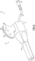
FIG. 2 is an assembled, perspective view of the shieldable needle device ofFIG. 1 in accordance with an embodiment of the present invention. -
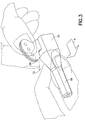
FIG. 3 is a perspective view of the shieldable needle device ofFIG. 2 with a packaging cover being removed in accordance with an embodiment of the present invention. -
FIG. 4 is a perspective view of the shieldable needle device ofFIG. 2 with the packaging cover removed, with a wing assembly in a dorsal position, and first and second drive members in a folded biased position in accordance with an embodiment of the present invention. -
FIG. 5 is a cross-sectional view taken along line 5-5 of the shieldable needle device ofFIG. 4 in accordance with an embodiment of the present invention. -
FIG. 6 is a perspective view of the shieldable needle device ofFIG. 2 with the packaging cover removed, with the wing assembly in a laterally extending position, and the first and second drive members in an extended position in accordance with an embodiment of the present invention. -
FIG. 7 is a plan view of the shieldable needle device ofFIG. 6 in accordance with an embodiment of the present invention. -
FIG. 8 is a cross-sectional view taken along line 8-8 of the shieldable needle device ofFIG. 6 in accordance with an embodiment of the present invention. -
FIG. 9A is a perspective view of an exemplary connection means, in an open position, between a first drive member or a second drive member and a hub or a tip guard assembly of the shieldable needle device ofFIG. 1 in accordance with an example not being part of the present invention. -
FIG. 9B is a side elevation cross-sectional view of the exemplary connection means ofFIG. 9A , in a locked position, between a first drive member or a second drive member and a hub or a tip guard assembly of the shieldable needle device ofFIG. 1 in accordance with an example not being part of the present invention. -
FIG. 10 is a perspective view of another exemplary connection means, in a locked position, between a first drive member or a second drive member and a hub or a tip guard assembly of the shieldable needle device ofFIG. 1 in accordance with an example not being part of the present invention. -
FIG. 11 is a perspective view of yet another exemplary connection means, in an open position, between a first drive member or a second drive member and a hub or a tip guard assembly of the shieldable needle device ofFIG. 1 in accordance with an example not being part of the present invention. - Corresponding reference characters indicate corresponding parts throughout the several views. The exemplifications set out herein illustrate exemplary embodiments of the disclosure, and such exemplifications are not to be construed as limiting the scope of the disclosure in any manner.
- The following description is provided to enable those skilled in the art to make and use the described embodiments contemplated for carrying out the invention. Various modifications, variations, and alternatives, however, will remain readily apparent to those skilled in the art. Any and all such modifications, variations, and alternatives are intended to fall within the scope of the present invention.
- For purposes of the description hereinafter, the terms "upper", "lower", "right", "left", "vertical", "horizontal", "top", "bottom", "lateral", "longitudinal", and derivatives thereof shall relate to the invention as it is oriented in the drawing figures. However, it is to be understood that the invention may assume various alternative variations, except where expressly specified to the contrary. It is also to be understood that the specific devices illustrated in the attached drawings, and described in the following specification, are simply exemplary embodiments of the invention. Hence, specific dimensions and other physical characteristics related to the embodiments disclosed herein are not to be considered as limiting.
- In the following discussion, "distal" refers to a direction generally toward an end of a needle assembly adapted for contact with a patient, and "proximal" refers to the opposite direction of distal, i.e., away from the end of a needle assembly adapted for contact with a patient. For purposes of this disclosure, the above-mentioned references are used in the description of the components of a shieldable needle device in accordance with the present disclosure.
- References to "embodiments" throughout the description which are not under the scope of the appended claims represent possible examples and are therefore not part of the present invention unless the context clearly dictates otherwise. The invention is defined by the appended claims.
- Referring to
FIGS. 1 and2 , ablood collection assembly 10 includes ashieldable needle device 12, aflexible tube 14 extending fromshieldable needle device 12, afixture 16 mounted totube 14, and apackaging cover 18 removably mounted to portions ofshieldable needle device 12opposite tube 14. In one embodiment, cover 18 may be removably mounted toshieldable needle device 12 through a frictional engagement, interference fit, or similar securement method.Blood collection assembly 10 includes aneedle cannula 20 having aproximal end 32, an opposingdistal end 34, and alumen 36 extending between the ends.Proximal end 32 ofneedle cannula 20 is securely mounted with ahub 22 so that acentral passage 44 ofhub 22 is in fluid communication withlumen 36 ofneedle cannula 20. - Thin flexible
thermoplastic tubing 14 may be connected tohub 22 so thattubing 14 is in fluid communication withlumen 36 ofneedle cannula 20. For example,flexible tubing 14 can be mounted to aproximal end 40 ofhub 22 such that the passage throughtubing 14 communicates withlumen 36 ofneedle cannula 20. The end oftubing 14 remote fromneedle cannula 20 may includefixture 16 mounted thereon for connectingneedle cannula 20 to a blood collection tube or some other receptacle. For example,fixture 16 enablesneedle cannula 20 andtubing 14 to be placed in communication with an appropriate receptacle, such as a blood collection tube. The specific construction offixture 16 will depend upon the characteristics of the receptacle to whichfixture 16 will be connected. -
Blood collection assembly 10 can be packaged substantially in the condition shown inFIG. 2 in protective packaging, such as in a blister package. Prior to use,blood collection assembly 10 is removed from any protective package, andfixture 16 may be connected to an appropriate receptacle for providing fluid communication withlumen 36 extending throughneedle cannula 20 as will described in more detail below. - Referring to
FIGS. 1 and4-8 ,shieldable needle device 12 includespackaging cover 18,needle cannula 20,hub 22, atip guard assembly 24, awing assembly 26, afirst drive member 28, and asecond drive member 30.First drive member 28 andsecond drive member 30 are configured for movingtip guard assembly 24 as will be described in more detail below. - Referring to
FIG. 1 ,first drive member 28 is separate and distinct fromsecond drive member 30. By having twoseparate drive members shieldable needle device 12 provides for better and more consistent locking out oftip guard assembly 24 to the distal position (FIGS. 6-8 ) in whichtip guard assembly 24 protectively surrounds and shieldsdistal end 34 ofneedle cannula 20. This is achieved because by having twoseparate drive members members FIGS. 2-5 ) to the extended position (FIGS. 6-8 ) can be achieved. In this manner,shieldable needle device 12 provides more consistent locking out oftip guard assembly 24 to the distal position in which thetip guard assembly 24 protectively surrounds and shieldsdistal end 34 ofneedle cannula 20. The twodrive members needle cannula 20. Referring toFIGS. 6 and7 , by having twoseparate drive members needle cannula 20 is protectively surrounded and safely shielded. As shown inFIGS. 6 and7 , the twodrive members tip guard assembly 24, substantially completely surround andshield needle cannula 20. Furthermore, the twoseparate drive members needle cannula 20. In this manner, no portion ofneedle cannula 20 is exposed thereby significantly reducing the risk of accidental needle stick injuries. - Referring to
FIG. 1 ,needle cannula 20 includes aproximal end 32 and an opposingdistal end 34, withlumen 36 extending throughneedle cannula 20 fromproximal end 32 todistal end 34.Distal end 34 ofneedle cannula 20 is beveled to define asharp puncture tip 38, such as an intravenous puncture tip.Puncture tip 38 is provided for insertion into a patient's blood vessel, such as a vein, and is therefore designed to provide ease of insertion and minimal discomfort during venipuncture. - Referring to
FIG. 1 ,shieldable needle device 12 includeshub 22. In one embodiment,hub 22 is a unitary structure, desirably molded from a thermoplastic material. In another embodiment,hub 22 may be integrally formed withwing assembly 26 as discussed below. In such an embodiment, the integral component ofhub 22 andwing assembly 26 forms a retainer member that supportsproximal end 32 ofneedle cannula 20 and that is movable between an open position (FIGS. 6-8 ) and a retaining position (FIGS. 2-5 ). -
Hub 22 includes aproximal end 40, an opposingdistal end 42, and is defined by a rigid structure orhub structure 46 extending between the ends.Hub 22 also includeshub connecting tube 52 disposed within a central cavity portion ofhub structure 46 and defining a distal opening 54 for receivingproximal end 32 ofneedle cannula 20. In this manner,hub 22 is configured to supportproximal end 32 ofneedle cannula 20.Needle cannula 20 can be positioned within distal opening 54 ofhub 22 so that a portion ofneedle cannula 20 extends fromdistal end 42 ofhub 22. In one embodiment,needle cannula 20 andhub 22 may be separate parts which are fixedly attached and secured through an appropriate medical grade adhesive, for example, epoxy or similar adhesive material. In another embodiment,needle cannula 20 andhub 22 may form an integral component. For example,needle cannula 20 andhub 22 may be integrally molded in a two-step molding process.Hub connecting tube 52 also defines aproximal opening 56 which is adapted to receiveflexible tube 14 as shown inFIG. 2 , or other medical device, such as a tube holder or similar component.Hub connecting tube 52 also defines acentral passage 44 extending throughhub connecting tube 52 fromproximal end 40 todistal end 42. -
Hub 22 includes structure for mating withfirst drive member 28 andsecond drive member 30. For example, afirst side surface 58 ofdistal end 42 ofhub 22 may include afirst connection element 48 and a second connection element 50 for connection withfirst drive member 28. An opposingsecond side surface 60 ofdistal end 42 ofhub 22 may also include afirst connection element 48 and a second connection element 50 for connection withsecond drive member 30. In one embodiment,first connection element 48 and second connection element 50 may include two button elements 62 for connection withfirst drive member 28 andsecond drive member 30, respectively, as will be discussed in more detail below. In other embodiments,hub 22 may include different types of structures for mating withfirst drive member 28 andsecond drive member 30 as will be described in more detail below and with reference toFIGS. 9A-11 . - Referring to
FIG. 1 ,shieldable needle device 12 includeswing assembly 26. In one embodiment,wing assembly 26 may be a unitary structure, desirably formed of a flexible material. As discussed above, in another embodiment,hub 22 andwing assembly 26 may be integrally molded in a two-step molding process. In one embodiment,hub 22 may be formed from a thermoplastic material andwing assembly 26 may be formed of a flexible material. - In some embodiments,
hub 22 andwing assembly 26 are separate pieces rather than being integrally molded. In one such embodiment,hub 22 andwing assembly 26 may be separate parts which are fixedly attached and secured through an appropriate medical grade adhesive, for example, epoxy or similar adhesive material. In other embodiments,hub 22 may be secured towing assembly 26 by a snap fit mechanism, a locking tab mechanism, a spring loaded locking mechanism, a latch, or other similar mechanism. -
Wing assembly 26 includes abody portion 64 extending between a pair ofwings first wing 66 and asecond wing 68. In an embodiment in whichhub 22 andwing assembly 26 are separate parts,body portion 64 ofwing assembly 26 may be fixedly attached to theunderside 63 ofhub 22, thereby allowingwings hub structure 46 at opposing sides thereof.Wing assembly 26 provides a component for assisting in positioning, stabilizing, and placement ofshieldable needle device 12 andblood collection assembly 10 during a blood collection procedure.Wings FIGS. 6-8 ) in which they are substantially planar, to a bent dorsal position (FIGS. 2-5 ). In one embodiment,wings wings body portion 64 ofwing assembly 26 may include skiveportions 70 to assist in the folding ofwings - Referring to
FIG. 1 ,shieldable needle device 12 includestip guard assembly 24.Tip guard assembly 24 extends co-axially aboutneedle cannula 20 and is axially movable alongneedle cannula 20 between a proximal position (FIGS. 2-5 )adjacent hub 22 and a distal position (FIGS. 6-8 )adjacent puncture tip 38 ofneedle cannula 20, as will be described in more detail later. Withtip guard assembly 24 in the distal position,tip guard 24 protectively surroundsdistal end 34 ofneedle cannula 20. -
Tip guard assembly 24 includes atip guard housing 72 and aprotective clip 74.Housing 72 is a unitary structure, desirably molded from a thermoplastic material, including aproximal end 76, adistal end 78, a recessedslot area 80 located atproximal end 76, and an internal chamber 82 (FIGS. 5 and8 ) extending between the ends. A portion ofinternal chamber 82 adjacentdistal end 78 defines anenlarged clip cavity 84, as shown inFIGS. 5 and8 . Additionally,tip guard assembly 24 includes structure for mating withfirst drive member 28 andsecond drive member 30. For example, afirst side surface 92 ofdistal end 78 oftip guard housing 72 may include aconnection element 86 for connection withfirst drive member 28. An opposingsecond side surface 94 ofdistal end 78 oftip guard housing 72 may also include aconnection element 86 for connection withsecond drive member 30. In one embodiment, afirst connection element 86 onfirst side surface 92 and asecond connection element 86 onsecond side surface 94 may each include a button element 88 for connection withfirst drive member 28 andsecond drive member 30, respectively. In other embodiments,tip guard housing 72 may include different types of structures for mating withfirst drive member 28 andsecond drive member 30 as will be described in more detail below and with reference toFIGS. 9A-11 .Tip guard housing 72 also includes a clip mounting post 90 (FIGS. 5 and8 ) that extends downwardly fromtip guard housing 72 at a location nearproximal end 76 oftip guard housing 72. -
Protective clip 74 is unitarily stamped and formed from a resiliently deflectable metallic material.Clip 74 includes aplanar spring leg 96 with aproximal end 98 and an opposeddistal end 100. A mountingaperture 102 extends throughspring leg 96 at a location adjacentproximal end 98. Mountingaperture 102 has a diameter approximately equal to or slightly less than the diameter ofclip mounting post 90 oftip guard housing 72. In this manner,clip mounting post 90 can be forced through mountingaperture 102 when the axis ofclip mounting post 90 and the axis of mountingaperture 102 are substantially collinear.Clip 74 also includes a lock outleg 104 that extends fromdistal end 100 ofspring leg 96. The extending lock outleg 104 enables secure protective engagement withpuncture tip 38 ofneedle cannula 20 withtip guard assembly 24 in the distal position (FIGS. 6-8 ). The extending lock outleg 104 further enables smooth axial sliding movement oftip guard assembly 24 alongneedle cannula 20, as will be explained further below. -
Hub 22 andtip guard assembly 24 are interconnected throughfirst drive member 28 andsecond drive member 30.First drive member 28 andsecond drive member 30 provide for axial movement oftip guard assembly 24 alongneedle cannula 20 from a proximal position (FIGS. 2-5 )adjacent hub 22 to a distal position (FIGS. 6-8 )adjacent puncture tip 38 ofneedle cannula 20, as will be described in more detail later. - Referring to
FIG. 1 ,shieldable needle device 12 includesfirst drive member 28 andsecond drive member 30. As discussed above,first drive member 28 is separate and distinct fromsecond drive member 30.First drive member 28 includes abody 110 having aproximal end 112 and an opposingdistal end 114. Similarly,second drive member 30 includes abody 130 having aproximal end 132 and an opposingdistal end 134.Bodies drive members FIGS. 2-5 ), and upon release of thewings drive members FIGS. 6-8 ). In this manner,first drive member 28 andsecond drive member 30 movetip guard assembly 24 from the proximal position (FIGS. 2-5 ) to the distal position (FIGS. 6-8 ). -
Proximal end 112 ofbody 110 offirst drive member 28 includes structure for mating withhub 22. For example, in one embodiment,proximal end 112 may include twoproximal openings 116 for receiving theconnection elements 48 and 50 onfirst side surface 58 ofdistal end 42 ofhub 22, thereby securing theproximal end 112 offirst drive member 28 to thedistal end 42 ofhub 22.Distal end 114 ofbody 110 offirst drive member 28 includes structure for mating withtip guard housing 72. For example, in one embodiment,distal end 114 ofbody 110 offirst drive member 28 may include adistal opening 118 to mate withfirst connection element 86 onfirst side surface 92 oftip guard assembly 24. - Similarly,
proximal end 132 ofbody 130 ofsecond drive member 30 includes structure for mating withhub 22. For example, in one embodiment,proximal end 132 may include twoproximal openings 136 for receiving theconnection elements 48 and 50 onsecond side surface 60 ofdistal end 42 ofhub 22, thereby securing theproximal end 132 ofsecond drive member 30 to thedistal end 42 ofhub 22.Distal end 134 ofbody 130 ofsecond drive member 30 includes structure for mating withtip guard housing 72. For example, in one embodiment,distal end 134 ofbody 130 ofsecond drive member 30 may include adistal opening 138 to mate withsecond connection element 86 onsecond side surface 94 oftip guard assembly 24. - Alternatively or in addition to the mechanical mating structure described above for the connection of
drive members hub 22 andtip guard assembly 24, respectively, thedrive members hub 22 andtip guard assembly 24 through the use of an adhesive or similar connection mechanism. - Since
drive members hub 22, and since thewings hub 22, movement of thewings drive members wings FIGS. 2-5 ), thewings first drive member 28 and thesecond drive member 30 in the folded biased position thereby maintainingtip guard assembly 24 in the proximal position. Additionally, with thewings FIG. 4 ) is formed betweenhub 22 and thewings first drive member 28 and a portion of thesecond drive member 30 internally withingap 150. In this manner,tip guard assembly 24 is maintained in a proximal positionadjacent hub 22. Upon release ofwings wings FIGS. 2-5 ), in which thewings FIGS. 6-8 ). In this manner,first drive member 28 andsecond drive member 30 are no longer retained bywings gap 150, andfirst drive member 28 andsecond drive member 30 are able to unfold to the extended position (FIGS. 6-8 ) to movetip guard assembly 24 from the proximal position to the distal position. In other words, sincefirst drive member 28 andsecond drive member 30 are fixedly attached to tipguard assembly 24, and sincetip guard assembly 24 is axially movable alongneedle cannula 20, the release ofwings first drive member 28 andsecond drive member 30 to unfold and axially movetip guard assembly 24 in a direction generally along arrow B (FIG. 6 ) away fromhub 22 and towarddistal end 32 ofneedle cannula 20, wheretip guard assembly 24 can effectively shield and protectivelysurround puncture tip 38 ofneedle cannula 20. -
Body 110 offirst drive member 28 andbody 130 ofsecond drive member 30 are formed of flexible materials that are biased toward the extended position, and therefore act as a means for storing energy to extendfirst drive member 28 andsecond drive member 30 towarddistal end 34 ofneedle cannula 20 upon corresponding movement betweenwings tip guard assembly 24 from the proximal position (FIGS. 2-5 ) to the distal position (FIGS. 6-8 ). - As discussed above, different types of structures can be used to connect
first drive member 28 orsecond drive member 30 tohub 22 ortip guard assembly 24.FIGS. 9A-11 illustrate configurations of different types of connection structures. - Referring to
FIGS. 9A and 9B , aconnection structure 200 includes a drivemember receiving portion 202 and a lockingportion 204 hingedly connected via ahinge 206. Drivemember receiving portion 202 includes a receivingsurface 208 and apost 210 extending from receivingsurface 208. Lockingportion 204 defines anaperture 216 and includeslatch members 212 having locking ends 214. - Referring to
FIGS. 9A and 9B , adrive member 28A includes abody 110A having aproximal end 112A defining anopening 116A. To securedrive member 28A toconnection structure 200, opening 116A ofbody 110A is disposed overpost 210 of drivemember receiving portion 202 as shown inFIG. 9A . In this position, lockingportion 204 can be pivoted in a direction generally along arrow C (FIG. 9A ) abouthinge 206 to the locking position shown inFIG. 9B . In this locking position, post 210 of drivemember receiving portion 202 is received withinaperture 216 of lockingportion 204 and locking ends 214 oflatch members 212 are lockingly engaged with drivemember receiving portion 202 to provide a secure connection betweendrive member 28A andconnection structure 200.Connection structure 200 can be used withhub 22 ortip guard assembly 24 to securely connectfirst drive member 28 orsecond drive member 30 tohub 22 ortip guard assembly 24. - Referring to
FIG. 10 , aconnection structure 300 includes a drivemember receiving portion 302 having a lockingwall 304 at adistal end 308 and defining a receivingchannel 306 at aproximal end 312. Drivemember receiving portion 302 also defines a drivemember receiving slot 314 atdistal end 308. Referring toFIG. 10 , adrive member 28B includes body a 110B having aproximal end 112B and a protrudingportion 120B located adjacentproximal end 112B. Protrudingportion 120B may be formed of a deformable resilient material. - To secure
drive member 28B toconnection structure 300, protrudingportion 120B ofbody 110B ofdrive member 28B is inserted into receivingslot 314 ofconnection structure 300 so that protrudingportion 120B can slide through and past lockingwall 304. Because protrudingportion 120B is formed of a deformable resilient material, lockingwall 304 can deform protrudingportion 120B as protrudingportion 120B slides through receivingslot 314. Once protrudingportion 120B extends beyond lockingwall 304, protrudingportion 120B is able to return back to its original form as shown inFIG. 10 . Once protrudingportion 120B is in the locked position ofFIG. 10 , lockingwall 304 forms a physical barrier that locks protrudingportion 120B withinslot 314 so thatdrive member 28B can not be pulled out ofconnection structure 300.Connection structure 300 can be used withhub 22 ortip guard assembly 24 to securely connectfirst drive member 28 orsecond drive member 30 tohub 22 ortip guard assembly 24. For example, referring toFIG. 10 , receivingchannel 306 ofconnection structure 300 is capable of securely receiving a hub or atip guard assembly 310. - Referring to
FIG. 11 , aconnection structure 400 includes a drivemember receiving portion 402 and a lockingportion 404 hingedly connected via ahinge 406. Drivemember receiving portion 402 includes a receivingsurface 408 and apost 410 extending from receivingsurface 408. Lockingportion 404 defines anaperture 416 and includes alatch member 412 having a lockingend 414. - Referring to
FIG. 11 , adrive member 28C includes abody 110C having aproximal end 112C defining anopening 116C. To securedrive member 28C toconnection structure 400, opening 116C ofbody 110C is disposed overpost 410 of drivemember receiving portion 402 as shown inFIG. 11 . In this position, lockingportion 404 can be pivoted in a direction generally along arrow D (FIG. 11 ) abouthinge 406 to a locking position. In the locking position, post 410 of drivemember receiving portion 402 is received withinaperture 416 of lockingportion 404 and lockingend 414 oflatch member 412 is lockingly engaged with drivemember receiving portion 402 to provide a secure connection betweendrive member 28C andconnection structure 400.Connection structure 400 functions similarly toconnection structure 200 described above.Connection structure 400 can be used withhub 22 ortip guard assembly 24 to securely connectfirst drive member 28 orsecond drive member 30 tohub 22 ortip guard assembly 24. - Assembly of
shieldable needle device 12 may be accomplished as follows.Tip guard assembly 24 is assembled by forcingclip mounting post 90 oftip guard housing 72 through mountingaperture 102 ofprotective clip 74.Spring leg 96 ofclip 74 is then urged downwardly or away frominternal chamber 82 throughtip guard housing 72.First drive member 28 andsecond drive member 30 are then interconnected betweentip guard assembly 24 andhub 22 by depressingproximal openings connection elements 48 and 50 on respective side surfaces 58 and 60 ofhub 22 and depressingdistal openings connection element 86 on respective side surfaces 92 and 94 of tip guard assembly, respectively, as described above.Distal end 34 ofneedle cannula 20 is then passed throughcentral passage 44 ofhub 22, and urged intointernal chamber 82 atproximal end 76 oftip guard housing 72. The downward deflection ofspring leg 96 enablesdistal end 34 ofneedle cannula 20 to be passed entirely throughtip guard housing 72 as shown inFIG. 5 .Spring leg 96 can be released afterpuncture tip 38 ofneedle cannula 20 passes entirely throughtip guard housing 72. In this manner, the end of lock outleg 104 will be biased against and slide alongneedle cannula 20.Tip guard assembly 24 is then slid proximally alongneedle cannula 20 into a positionadjacent hub 22, withfirst drive member 28 andsecond drive member 30 each folded over itself into a bent, biased position, primed for use, as shown inFIGS. 2-5 .Wings FIGS. 2-5 .Packaging cover 18 is then urged overpuncture tip 38 and urged proximally overneedle cannula 20, withpuncture tip 38 safely maintained and disposed withinpackaging cover 18, and with alateral wall 17 and aslot 19 ofpackaging cover 18 maintainingwings FIGS. 2 and3 .Packaging cover 18 is desirably constructed of a rigid material which is capable of maintainingwings - As discussed above,
blood collection assembly 10 can be packaged substantially in the condition shown inFIG. 2 in protective packaging, such as in a blister package. Prior to use,blood collection assembly 10 is removed from any protective package, andfixture 16 may be connected to an appropriate receptacle for providing fluid communication withlumen 36 extending throughneedle cannula 20. - In use,
blood collection assembly 10 is provided withshieldable needle device 12 assembled and includingflexible tube 14 extending fromshieldable needle device 12 and connected tofixture 16. After removingblood collection assembly 10 from its protective packaging, it can be assembled with other appropriate medical equipment for use. For example, a non-patient needle assembly and a needle holder may be connected toblood collection assembly 10 throughfixture 16. - To prepare for use of
blood collection assembly 10, the user graspsblood collection assembly 10 atshieldable needle device 12, placing a thumb and forefinger onwings wings FIG. 3 . Bothwings bodies second drive members Packaging cover 18 is then grasped and urged distally in a direction generally along arrow A (FIG. 3 ) to disengagecover 18 fromneedle cannula 20, thereby exposingpuncture tip 38 ofneedle cannula 20. - The medical practitioner can then urge
puncture tip 38 atdistal end 34 ofneedle cannula 20 into a targeted blood vessel of a patient, whilewings Tip guard assembly 24 is maintained in the proximal position (FIGS. 3-5 ) due to the grip by the user's fingers betweenwings first drive member 28 andsecond drive member 30 in the folded, biased position. - After the targeted blood vessel has been accessed, the medical practitioner can release
wings first drive member 28 andsecond drive member 30 are free to move from the folded biased position to the extended unfolded position, due to the bias exerted bybodies first drive member 28 andsecond drive member 30 through release ofwings bodies first drive member 28 andsecond drive member 30 to extend, thereby propellingtip guard assembly 24 distally alongneedle cannula 20 in an axial direction generally along arrow B (FIG. 6 ), withtip guard assembly 24 sliding or gliding alongneedle cannula 20 towarddistal end 34. Distal movement oftip guard assembly 24 will terminate whendistal end 78 oftip guard housing 72 contacts the skin of the patient near the puncture site. - Upon completion of the procedure, such as when all desired samples have been drawn,
needle cannula 20 is withdrawn from the patient. This removal ofneedle cannula 20 from the patient will permit further extension ofbodies first drive member 28 andsecond drive member 30 and a corresponding distal movement oftip guard assembly 24 in an axial direction generally along arrow B (FIG. 6 ). Aftertip guard assembly 24 is moved alongneedle cannula 20 to thedistal end 34, lock outleg 104 ofclip 74 will pass distally beyondpuncture tip 38 ofneedle cannula 20. The inherent resiliency ofspring leg 96 ofclip 74 will urge lock outleg 104 overpuncture tip 38 ofneedle cannula 20 as shown inFIG. 8 . In this manner, a return movement oftip guard assembly 24 to the proximal position is prevented. Furthermore,first drive member 28 andsecond drive member 30 have overall dimensions that will prevent movement oftip guard assembly 24 distally beyondneedle cannula 20. In this manner,puncture tip 38 ofneedle cannula 20 is safely shielded.Blood collection assembly 10 may then be appropriately and safely discarded. - Since
wings wings shieldable needle device 12. In particular, after release ofwings tip guard assembly 24 to the distal position, theneedle cannula 20 is shielded andwings hub 22. Sincewings wings FIG. 4 , to allow a user to grip theshieldable needle device 12 for removal from the patient. Thewings blood collection assembly 10 at a position remote from the used needle tip ofcannula 20. Additionally,first drive member 28 andsecond drive member 30 can be actuated whilepuncture tip 38 is within the patient's blood vessel, thereby beginning axial movement oftip guard assembly 24 alongneedle cannula 20. In other embodiments,first drive member 28 andsecond drive member 30 can be actuated afterpuncture tip 38 is removed from the patient's blood vessel. - The shielding feature of the present invention is passively activated upon normal usage of the device. In particular, upon removal of the packaging cover prior to insertion, the safety feature is primed and charged, ready for shielding the needle once the user releases the wing structure after insertion into a patient. Moreover, as described above, passive shielding of the needle cannula is automatically achieved merely by removing the needle cannula from the patient.
- In some instances, the needle device may be dropped or knocked from the hand of the medical practitioner either before venipuncture or during a medical procedure. The passive shielding described above will commence automatically when the needle device is dropped or knocked from the medical practitioner's hand. Thus, the automatic shielding may be triggered by the intentional or unintentional release of the wings by the medical practitioner.
- Moreover, a medical practitioner does not always enter the targeted blood vessel during the first venipuncture attempt. However, a medical practitioner typically retains a close grip on the needle device until the targeted blood vessel has been entered. In this manner, the continued gripping of the wings will prevent the needle from shielding until the targeted blood vessel has been punctured. The second attempt at accessing a targeted blood vessel generally is a very low risk procedure in which the practitioner's hand is spaced considerably from the puncture tip of the needle cannula. Thus, the blood collection set according to the present invention does not involve the inconvenience of having to use a new blood collection set following each unsuccessful venipuncture attempt.
- While the needle assembly of the present invention has been described in terms of one embodiment for use in connection with a blood collection system, it is further contemplated that the needle assembly could be used with other medical procedures, such as in conjunction with a conventional intravenous infusion set, which are well known in the art for use with needle assemblies.
- While this disclosure has been described as having exemplary designs, the present disclosure can be further modified within the scope of this disclosure. This application is therefore intended to cover any variations, uses, or adaptations of the disclosure. Further, this application is intended to cover such departures from the present disclosure as come within known or customary practice in the art to which this disclosure pertains and which fall within the limits of the appended claims.
Claims (3)
- A shieldable needle device (12) comprising:a needle cannula (20) having a proximal end (32) and a distal end (34);a retainer member (26) supporting the proximal end (32) of the needle cannula, the retainer member (26) movable between an open position and a retaining position;a tip guard (24) axially movable with respect to the needle cannula (20) from a first position adjacent the retainer member to a second position in which the tip guard (24) shields the distal (34)_end of the needle cannula (20);a first drive member (28) extendable between a biased position and an extended position for moving the tip guard (24) from the first position to the second position, the first drive member (28) having a proximal end (112) connected to the retainer member and a distal end (114) connected to the tip guard (24); anda second drive member (30) extendable between a biased position and an extended position for moving the tip guard (24) from the first position to the second position, the second drive member (30) having a proximal end (132) connected to the retainer member and a distal end (134) connected to the tip guard,wherein, with the retainer member (26) in the retaining position, the retainer member (26) retains the first drive member (28) and the second drive member (30) in the biased position thereby maintaining the tip guard (24) in the first position, and movement of the retainer member from the retaining position to the open position releases retainment of the first drive member (28) and the second drive member (30) thereby allowing the first drive member (28) and the second drive member (30) to transition to the extended position and move the tip guard (24) from the first position to the second position, andcharacterized by, when the first drive member (28) and the second drive member (30) are each in the extended position, the first drive member (28), the second drive member (30), and the tip guard (24) completely surround and shield the needle cannula (20).
- The shieldable needle device (12) of claim 1, wherein the first drive member (28)_and the second drive member (30) are at least partially folded in the biased position.
- The shieldable needle device (12)_of claim 2, wherein movement of the retainer member from the retaining position to the open position releases retainment of the first drive member (28) and the second drive member (30) thereby allowing the first drive member (28) and the second drive member (30)_to unfold to the extended position and move the tip guard (24) from the first position to the second position.
Applications Claiming Priority (4)
| Application Number | Priority Date | Filing Date | Title |
|---|---|---|---|
| US13/677,662 US10524710B2 (en) | 2012-11-15 | 2012-11-15 | Passive double drive member activated safety blood collection device |
| EP12808548.7A EP2919832B1 (en) | 2012-11-15 | 2012-11-16 | Passive double drive member activated safety blood collection device |
| PCT/US2012/065472 WO2014077831A1 (en) | 2012-11-15 | 2012-11-16 | Passive double drive member activated safety blood collection device |
| EP17174832.0A EP3246057B1 (en) | 2012-11-15 | 2012-11-16 | Passive double drive member activated safety blood collection device |
Related Parent Applications (2)
| Application Number | Title | Priority Date | Filing Date |
|---|---|---|---|
| EP17174832.0A Division EP3246057B1 (en) | 2012-11-15 | 2012-11-16 | Passive double drive member activated safety blood collection device |
| EP12808548.7A Division EP2919832B1 (en) | 2012-11-15 | 2012-11-16 | Passive double drive member activated safety blood collection device |
Publications (2)
| Publication Number | Publication Date |
|---|---|
| EP3517154A1 EP3517154A1 (en) | 2019-07-31 |
| EP3517154B1 true EP3517154B1 (en) | 2020-09-09 |
Family
ID=47459095
Family Applications (3)
| Application Number | Title | Priority Date | Filing Date |
|---|---|---|---|
| EP19164108.3A Active EP3517154B1 (en) | 2012-11-15 | 2012-11-16 | Passive double drive member activated safety blood collection device |
| EP12808548.7A Active EP2919832B1 (en) | 2012-11-15 | 2012-11-16 | Passive double drive member activated safety blood collection device |
| EP17174832.0A Active EP3246057B1 (en) | 2012-11-15 | 2012-11-16 | Passive double drive member activated safety blood collection device |
Family Applications After (2)
| Application Number | Title | Priority Date | Filing Date |
|---|---|---|---|
| EP12808548.7A Active EP2919832B1 (en) | 2012-11-15 | 2012-11-16 | Passive double drive member activated safety blood collection device |
| EP17174832.0A Active EP3246057B1 (en) | 2012-11-15 | 2012-11-16 | Passive double drive member activated safety blood collection device |
Country Status (10)
| Country | Link |
|---|---|
| US (2) | US10524710B2 (en) |
| EP (3) | EP3517154B1 (en) |
| JP (1) | JP6294338B2 (en) |
| CN (3) | CN203763091U (en) |
| AU (1) | AU2012394400B2 (en) |
| BR (1) | BR112015011144B1 (en) |
| CA (2) | CA2996397C (en) |
| ES (2) | ES2642288T3 (en) |
| MX (1) | MX361968B (en) |
| WO (1) | WO2014077831A1 (en) |
Families Citing this family (10)
| Publication number | Priority date | Publication date | Assignee | Title |
|---|---|---|---|---|
| AR070764A1 (en) * | 2007-12-07 | 2010-05-05 | Pyng Medical Corp | APPLIANCES AND METHODS TO ENTER OSEOS PORTALS |
| US10524710B2 (en) * | 2012-11-15 | 2020-01-07 | Becton, Dickinson And Company | Passive double drive member activated safety blood collection device |
| US10112033B2 (en) * | 2014-07-08 | 2018-10-30 | Becton, Dickinson And Company | Intravenous needle assembly having blood dispensing capabilities |
| CN104490405B (en) * | 2015-01-09 | 2016-06-29 | 王君 | A kind of winding ruins pattern disposable safe blood taking needle |
| CN104473654B (en) * | 2015-01-09 | 2016-05-11 | 成浩 | A kind of hiding winding ruined pattern disposable safe blood taking needle |
| CN105079922B (en) * | 2015-09-24 | 2018-11-02 | 柳城县妇幼保健院 | Disposable anti-needle stabs device |
| US10179205B2 (en) | 2016-02-04 | 2019-01-15 | Novum Vascular, Llc | Passive safety huber needle |
| JP6664270B2 (en) * | 2016-04-26 | 2020-03-13 | 株式会社トップ | Medical needle with protector |
| CN112292079A (en) * | 2018-05-01 | 2021-01-29 | 贝克顿·迪金森公司 | Squeeze-activated blood collection set |
| US11865274B2 (en) * | 2019-08-28 | 2024-01-09 | Becton, Dickinson And Company | Catheter system for pediatric treatment |
Family Cites Families (70)
| Publication number | Priority date | Publication date | Assignee | Title |
|---|---|---|---|---|
| US3640275A (en) | 1970-05-05 | 1972-02-08 | Burron Medical Prod Inc | Intravenous needle assembly |
| US3840008A (en) | 1972-04-18 | 1974-10-08 | Surgical Corp | Safety hypodermic needle |
| US4139009A (en) | 1976-11-23 | 1979-02-13 | Marcial Alvarez | Hypodermic needle assembly with retractable needle cover |
| US4725267A (en) | 1987-05-06 | 1988-02-16 | Vaillancourt Vincent L | Post-injection needle sheath |
| US4735618A (en) | 1987-07-20 | 1988-04-05 | Henry E. Szachowicz, Jr. | Protective enclosure for hypodermic syringe |
| US4790828A (en) | 1987-08-07 | 1988-12-13 | Dombrowski Mitchell P | Self-capping needle assembly |
| US4867172A (en) | 1988-02-23 | 1989-09-19 | Habley Medical Technology Corporation | Collapsible blood collector |
| US4911694A (en) | 1988-05-06 | 1990-03-27 | Dolan Michael F | Syringe needle sheath |
| US4867746A (en) | 1988-05-23 | 1989-09-19 | Becton, Dickinson And Company | Needle shield |
| US4909794A (en) | 1988-06-24 | 1990-03-20 | Habley Medical Technology Corporation | Combination retractable needle cannula and cannula lock for a medication carpule |
| US4892521A (en) | 1988-08-03 | 1990-01-09 | Lincoln Mills, Inc. | Protective cover for hypodermic needle |
| US4955866A (en) | 1988-10-19 | 1990-09-11 | University Of Florida | Hypodermic needle recapping device |
| US5059180A (en) | 1989-11-21 | 1991-10-22 | Mclees Donald J | Automatic needle tip guard |
| US4998922A (en) | 1990-02-23 | 1991-03-12 | Kuracina Thomas C | Safety syringe cap minimizing needle-stick probability |
| US5176655A (en) | 1990-11-08 | 1993-01-05 | Mbo Laboratories, Inc. | Disposable medical needle and catheter placement assembly having full safety enclosure means |
| US5098401A (en) | 1991-01-04 | 1992-03-24 | Lange Andries G De | Disposable automatic needle cover assembly with safety lock |
| GB9120416D0 (en) | 1991-09-25 | 1991-11-06 | Sterimatic Holdings Ltd | Catheter placement units |
| US5256152A (en) | 1991-10-29 | 1993-10-26 | Marks Lloyd A | Safety needle and method of using same |
| US5328483A (en) | 1992-02-27 | 1994-07-12 | Jacoby Richard M | Intradermal injection device with medication and needle guard |
| US5242418A (en) | 1992-05-22 | 1993-09-07 | Weinstein James D | Protective means for a needle or similar cannula medical device |
| JPH07506753A (en) | 1992-07-31 | 1995-07-27 | ステイン、リカード・シース・オックスフォード | needle protector |
| US5295972A (en) | 1992-08-04 | 1994-03-22 | Metatech Corporation | Hypodermic syringe with protective cap |
| US5271070A (en) | 1992-11-06 | 1993-12-14 | Xerox Corporation | Multi-dimensional error diffusion technique |
| US5250031A (en) | 1992-12-14 | 1993-10-05 | The George Washington University | Locking needle cover |
| FR2701848B1 (en) | 1993-02-26 | 1995-05-05 | Daniel Guillet | Protective device for a syringe needle. |
| US5334155A (en) | 1993-04-06 | 1994-08-02 | Daniel Sobel | Hypodermic syringe needle guard |
| US5348544A (en) | 1993-11-24 | 1994-09-20 | Becton, Dickinson And Company | Single-handedly actuatable safety shield for needles |
| AU654464B3 (en) | 1994-04-20 | 1994-11-03 | Noble House Group Pty Ltd | Protective sheath |
| BR9502150A (en) | 1994-05-30 | 1996-01-02 | Carlos Maria Baron | Retractable safety guard for syringe needles in general |
| US5713872A (en) | 1994-06-09 | 1998-02-03 | Feuerborn; Arthur Mark | Flexing safety shield for hypodermic needles |
| US5584818A (en) | 1994-08-22 | 1996-12-17 | Morrison; David | Safety hypodermic needle and shielding cap assembly |
| US5423766A (en) | 1994-08-26 | 1995-06-13 | Becton, Dickinson And Company | Safety shield having spring tether |
| US5925020A (en) | 1994-11-22 | 1999-07-20 | Becton, Dickinson And Company | Needle point barrier |
| JP2727984B2 (en) | 1994-11-29 | 1998-03-18 | 日本電気株式会社 | Method for manufacturing semiconductor device |
| US5549571A (en) | 1995-04-18 | 1996-08-27 | Sak; Robert F. | Butterfly assembly with retractable needle cannula |
| US5630803A (en) | 1995-11-06 | 1997-05-20 | Tamaro; Frank A. | Safety cap assembly for needles |
| US5688241A (en) | 1996-04-15 | 1997-11-18 | Asbaghi; Hooman Ali | Automatic non-reusable needle guard |
| US5735827A (en) | 1996-09-26 | 1998-04-07 | Becton, Dickinson And Company | Needle assembly having locking enclosure |
| US5738665A (en) | 1996-09-26 | 1998-04-14 | Becton, Dickinson And Company | Shield and actuator for needles |
| US5779679A (en) | 1997-04-18 | 1998-07-14 | Shaw; Thomas J. | Winged IV set with retractable needle |
| US5951525A (en) | 1998-02-10 | 1999-09-14 | Specialized Health Products, Inc. | Manual safety medical needle apparatus and methods |
| FR2779655B1 (en) | 1998-06-11 | 2000-09-01 | Vygon | HYPODERMAL NEEDLE PROTECTOR |
| US6210371B1 (en) | 1999-03-30 | 2001-04-03 | Retractable Technologies, Inc. | Winged I.V. set |
| JP4348578B2 (en) | 1999-04-26 | 2009-10-21 | 株式会社ジェイ・エム・エス | Wing needle device |
| US6409706B1 (en) | 1999-05-14 | 2002-06-25 | Randall A. Loy | Safety syringe, fluid collection device, and associated methods |
| US6261264B1 (en) | 1999-07-23 | 2001-07-17 | Frank A. Tamaro | Safety cap assembly for needles |
| US6224576B1 (en) | 1999-11-04 | 2001-05-01 | Specialized Health Products, Inc. | Safety device for a needle having two sharpened ends |
| US6832992B2 (en) | 2000-03-07 | 2004-12-21 | Becton, Dickinson And Company | Passive safety device for needle of blood collection set |
| US6855130B2 (en) * | 2000-03-07 | 2005-02-15 | Becton, Dickinson And Company | Passive safety device for needle of IV infusion or blood collection set |
| US6537259B1 (en) | 2000-03-07 | 2003-03-25 | Becton, Dickinson And Company | Passive safety device |
| US6673047B2 (en) | 2001-01-05 | 2004-01-06 | Becton, Dickinson And Company | Blood collection set |
| US6743186B2 (en) | 2001-01-05 | 2004-06-01 | Becton, Dickinson And Company | Blood collection assembly |
| USD452313S1 (en) | 2001-01-08 | 2001-12-18 | Becton, Dickinson And Company | Needle assembly |
| USD452314S1 (en) | 2001-01-08 | 2001-12-18 | Becton, Dickinson And Company | Needle assembly |
| USD452003S1 (en) | 2001-01-08 | 2001-12-11 | Becton, Dickinson And Company | Needle assembly |
| AU3708902A (en) | 2001-05-04 | 2002-11-07 | Becton Dickinson & Company | Passively activated safely needle |
| KR20040039289A (en) | 2001-08-17 | 2004-05-10 | 벡톤 디킨슨 앤드 컴퍼니 | Blood collection assembly |
| JP2003093515A (en) | 2001-09-20 | 2003-04-02 | Top:Kk | Indwelling needle |
| EP1346740B1 (en) | 2002-03-19 | 2010-09-08 | Becton Dickinson and Company | Needle device |
| CA2422472A1 (en) | 2002-03-19 | 2003-09-19 | Volker Niermann | Needle assembly |
| CN1294998C (en) | 2002-03-21 | 2007-01-17 | 贝克顿迪肯森公司 | Safety device |
| US20030220587A1 (en) | 2002-05-23 | 2003-11-27 | Becton Dickinson And Company | Medical device |
| US6881202B2 (en) | 2002-05-28 | 2005-04-19 | Becton, Dickinson And Company | Needle assembly |
| US7422573B2 (en) | 2002-12-19 | 2008-09-09 | Becton, Dickinson And Company | Forward blunting wingset with leaf spring driven shield |
| US7041066B2 (en) | 2003-03-13 | 2006-05-09 | Becton, Dickinson & Company | Needle assembly |
| US20050119627A1 (en) * | 2003-12-01 | 2005-06-02 | Becton, Dickinson And Company | Selectively passive forward shielding medical needle device |
| US7150725B2 (en) * | 2003-12-17 | 2006-12-19 | Becton Dickinson And Company | Passive activated safety blood collection set |
| US20090198214A1 (en) * | 2008-02-01 | 2009-08-06 | Istvan Bognar | Butterfly Needle Devices and Methods Relating Thereto |
| US20110306992A1 (en) * | 2010-06-09 | 2011-12-15 | C.R. Bard, Inc. | Instruments for delivering transfascial sutures, transfascial suture assemblies, and methods of transfascial suturing |
| US10524710B2 (en) * | 2012-11-15 | 2020-01-07 | Becton, Dickinson And Company | Passive double drive member activated safety blood collection device |
-
2012
- 2012-11-15 US US13/677,662 patent/US10524710B2/en active Active
- 2012-11-16 ES ES12808548.7T patent/ES2642288T3/en active Active
- 2012-11-16 MX MX2015005781A patent/MX361968B/en active IP Right Grant
- 2012-11-16 ES ES19164108T patent/ES2832558T3/en active Active
- 2012-11-16 EP EP19164108.3A patent/EP3517154B1/en active Active
- 2012-11-16 EP EP12808548.7A patent/EP2919832B1/en active Active
- 2012-11-16 WO PCT/US2012/065472 patent/WO2014077831A1/en active Application Filing
- 2012-11-16 BR BR112015011144-0A patent/BR112015011144B1/en active IP Right Grant
- 2012-11-16 CA CA2996397A patent/CA2996397C/en active Active
- 2012-11-16 CA CA2891463A patent/CA2891463C/en active Active
- 2012-11-16 EP EP17174832.0A patent/EP3246057B1/en active Active
- 2012-11-16 JP JP2015543015A patent/JP6294338B2/en active Active
- 2012-11-16 AU AU2012394400A patent/AU2012394400B2/en active Active
-
2013
- 2013-11-14 CN CN201320717483.8U patent/CN203763091U/en not_active Expired - Lifetime
- 2013-11-14 CN CN201310565760.2A patent/CN103815918A/en active Pending
- 2013-11-14 CN CN201711347171.1A patent/CN107951495A/en active Pending
-
2019
- 2019-12-03 US US16/701,680 patent/US11564604B2/en active Active
Non-Patent Citations (1)
| Title |
|---|
| None * |
Also Published As
| Publication number | Publication date |
|---|---|
| US10524710B2 (en) | 2020-01-07 |
| CN107951495A (en) | 2018-04-24 |
| CN103815918A (en) | 2014-05-28 |
| ES2642288T3 (en) | 2017-11-16 |
| WO2014077831A1 (en) | 2014-05-22 |
| BR112015011144A2 (en) | 2017-07-11 |
| JP6294338B2 (en) | 2018-03-14 |
| CA2996397A1 (en) | 2014-05-22 |
| AU2012394400B2 (en) | 2016-10-20 |
| EP3246057A3 (en) | 2018-02-14 |
| CA2996397C (en) | 2020-05-26 |
| BR112015011144B1 (en) | 2021-01-12 |
| AU2012394400A1 (en) | 2015-05-28 |
| MX2015005781A (en) | 2016-03-11 |
| EP3246057B1 (en) | 2019-03-27 |
| JP2015534894A (en) | 2015-12-07 |
| ES2832558T3 (en) | 2021-06-10 |
| EP2919832B1 (en) | 2017-07-19 |
| CA2891463A1 (en) | 2014-05-22 |
| EP2919832A1 (en) | 2015-09-23 |
| CN203763091U (en) | 2014-08-13 |
| US20200100717A1 (en) | 2020-04-02 |
| EP3246057A2 (en) | 2017-11-22 |
| US20140135652A1 (en) | 2014-05-15 |
| CA2891463C (en) | 2018-04-10 |
| US11564604B2 (en) | 2023-01-31 |
| EP3517154A1 (en) | 2019-07-31 |
| MX361968B (en) | 2018-12-19 |
Similar Documents
| Publication | Publication Date | Title |
|---|---|---|
| US11564604B2 (en) | Passive double drive member activated safety blood collection device | |
| US7150725B2 (en) | Passive activated safety blood collection set | |
| US9878130B2 (en) | Passively shielding needle device | |
| US6936036B2 (en) | Blood collection agency | |
| US9402964B2 (en) | Passively shielding needle device | |
| US7422573B2 (en) | Forward blunting wingset with leaf spring driven shield | |
| US20050119627A1 (en) | Selectively passive forward shielding medical needle device | |
| US20030220587A1 (en) | Medical device | |
| JPH05503658A (en) | Disposable medical needle assemblies and catheter placement assemblies with fully secure enclosure means | |
| US20030181867A1 (en) | Needle assembly | |
| EP3077030B1 (en) | Blood collection device with double pivot shields |
Legal Events
| Date | Code | Title | Description |
|---|---|---|---|
| PUAI | Public reference made under article 153(3) epc to a published international application that has entered the european phase |
Free format text: ORIGINAL CODE: 0009012 |
|
| STAA | Information on the status of an ep patent application or granted ep patent |
Free format text: STATUS: THE APPLICATION HAS BEEN PUBLISHED |
|
| AC | Divisional application: reference to earlier application |
Ref document number: 2919832 Country of ref document: EP Kind code of ref document: P Ref document number: 3246057 Country of ref document: EP Kind code of ref document: P |
|
| AK | Designated contracting states |
Kind code of ref document: A1 Designated state(s): AL AT BE BG CH CY CZ DE DK EE ES FI FR GB GR HR HU IE IS IT LI LT LU LV MC MK MT NL NO PL PT RO RS SE SI SK SM TR |
|
| STAA | Information on the status of an ep patent application or granted ep patent |
Free format text: STATUS: REQUEST FOR EXAMINATION WAS MADE |
|
| 17P | Request for examination filed |
Effective date: 20200130 |
|
| RBV | Designated contracting states (corrected) |
Designated state(s): AL AT BE BG CH CY CZ DE DK EE ES FI FR GB GR HR HU IE IS IT LI LT LU LV MC MK MT NL NO PL PT RO RS SE SI SK SM TR |
|
| GRAP | Despatch of communication of intention to grant a patent |
Free format text: ORIGINAL CODE: EPIDOSNIGR1 |
|
| STAA | Information on the status of an ep patent application or granted ep patent |
Free format text: STATUS: GRANT OF PATENT IS INTENDED |
|
| RIC1 | Information provided on ipc code assigned before grant |
Ipc: A61B 5/15 20060101ALI20200226BHEP Ipc: A61M 5/32 20060101AFI20200226BHEP Ipc: A61B 5/153 20060101ALI20200226BHEP Ipc: A61M 5/158 20060101ALI20200226BHEP |
|
| INTG | Intention to grant announced |
Effective date: 20200325 |
|
| GRAS | Grant fee paid |
Free format text: ORIGINAL CODE: EPIDOSNIGR3 |
|
| GRAA | (expected) grant |
Free format text: ORIGINAL CODE: 0009210 |
|
| STAA | Information on the status of an ep patent application or granted ep patent |
Free format text: STATUS: THE PATENT HAS BEEN GRANTED |
|
| AC | Divisional application: reference to earlier application |
Ref document number: 2919832 Country of ref document: EP Kind code of ref document: P Ref document number: 3246057 Country of ref document: EP Kind code of ref document: P |
|
| AK | Designated contracting states |
Kind code of ref document: B1 Designated state(s): AL AT BE BG CH CY CZ DE DK EE ES FI FR GB GR HR HU IE IS IT LI LT LU LV MC MK MT NL NO PL PT RO RS SE SI SK SM TR |
|
| REG | Reference to a national code |
Ref country code: GB Ref legal event code: FG4D |
|
| REG | Reference to a national code |
Ref country code: AT Ref legal event code: REF Ref document number: 1310771 Country of ref document: AT Kind code of ref document: T Effective date: 20200915 Ref country code: CH Ref legal event code: EP |
|
| REG | Reference to a national code |
Ref country code: IE Ref legal event code: FG4D |
|
| REG | Reference to a national code |
Ref country code: DE Ref legal event code: R096 Ref document number: 602012072320 Country of ref document: DE |
|
| REG | Reference to a national code |
Ref country code: LT Ref legal event code: MG4D |
|
| PG25 | Lapsed in a contracting state [announced via postgrant information from national office to epo] |
Ref country code: FI Free format text: LAPSE BECAUSE OF FAILURE TO SUBMIT A TRANSLATION OF THE DESCRIPTION OR TO PAY THE FEE WITHIN THE PRESCRIBED TIME-LIMIT Effective date: 20200909 Ref country code: GR Free format text: LAPSE BECAUSE OF FAILURE TO SUBMIT A TRANSLATION OF THE DESCRIPTION OR TO PAY THE FEE WITHIN THE PRESCRIBED TIME-LIMIT Effective date: 20201210 Ref country code: LT Free format text: LAPSE BECAUSE OF FAILURE TO SUBMIT A TRANSLATION OF THE DESCRIPTION OR TO PAY THE FEE WITHIN THE PRESCRIBED TIME-LIMIT Effective date: 20200909 Ref country code: BG Free format text: LAPSE BECAUSE OF FAILURE TO SUBMIT A TRANSLATION OF THE DESCRIPTION OR TO PAY THE FEE WITHIN THE PRESCRIBED TIME-LIMIT Effective date: 20201209 Ref country code: NO Free format text: LAPSE BECAUSE OF FAILURE TO SUBMIT A TRANSLATION OF THE DESCRIPTION OR TO PAY THE FEE WITHIN THE PRESCRIBED TIME-LIMIT Effective date: 20201209 Ref country code: SE Free format text: LAPSE BECAUSE OF FAILURE TO SUBMIT A TRANSLATION OF THE DESCRIPTION OR TO PAY THE FEE WITHIN THE PRESCRIBED TIME-LIMIT Effective date: 20200909 Ref country code: HR Free format text: LAPSE BECAUSE OF FAILURE TO SUBMIT A TRANSLATION OF THE DESCRIPTION OR TO PAY THE FEE WITHIN THE PRESCRIBED TIME-LIMIT Effective date: 20200909 |
|
| REG | Reference to a national code |
Ref country code: NL Ref legal event code: MP Effective date: 20200909 |
|
| PG25 | Lapsed in a contracting state [announced via postgrant information from national office to epo] |
Ref country code: PL Free format text: LAPSE BECAUSE OF FAILURE TO SUBMIT A TRANSLATION OF THE DESCRIPTION OR TO PAY THE FEE WITHIN THE PRESCRIBED TIME-LIMIT Effective date: 20200909 Ref country code: RS Free format text: LAPSE BECAUSE OF FAILURE TO SUBMIT A TRANSLATION OF THE DESCRIPTION OR TO PAY THE FEE WITHIN THE PRESCRIBED TIME-LIMIT Effective date: 20200909 Ref country code: LV Free format text: LAPSE BECAUSE OF FAILURE TO SUBMIT A TRANSLATION OF THE DESCRIPTION OR TO PAY THE FEE WITHIN THE PRESCRIBED TIME-LIMIT Effective date: 20200909 |
|
| PG25 | Lapsed in a contracting state [announced via postgrant information from national office to epo] |
Ref country code: SM Free format text: LAPSE BECAUSE OF FAILURE TO SUBMIT A TRANSLATION OF THE DESCRIPTION OR TO PAY THE FEE WITHIN THE PRESCRIBED TIME-LIMIT Effective date: 20200909 Ref country code: RO Free format text: LAPSE BECAUSE OF FAILURE TO SUBMIT A TRANSLATION OF THE DESCRIPTION OR TO PAY THE FEE WITHIN THE PRESCRIBED TIME-LIMIT Effective date: 20200909 Ref country code: PT Free format text: LAPSE BECAUSE OF FAILURE TO SUBMIT A TRANSLATION OF THE DESCRIPTION OR TO PAY THE FEE WITHIN THE PRESCRIBED TIME-LIMIT Effective date: 20210111 Ref country code: CZ Free format text: LAPSE BECAUSE OF FAILURE TO SUBMIT A TRANSLATION OF THE DESCRIPTION OR TO PAY THE FEE WITHIN THE PRESCRIBED TIME-LIMIT Effective date: 20200909 Ref country code: EE Free format text: LAPSE BECAUSE OF FAILURE TO SUBMIT A TRANSLATION OF THE DESCRIPTION OR TO PAY THE FEE WITHIN THE PRESCRIBED TIME-LIMIT Effective date: 20200909 |
|
| PG25 | Lapsed in a contracting state [announced via postgrant information from national office to epo] |
Ref country code: IS Free format text: LAPSE BECAUSE OF FAILURE TO SUBMIT A TRANSLATION OF THE DESCRIPTION OR TO PAY THE FEE WITHIN THE PRESCRIBED TIME-LIMIT Effective date: 20210109 Ref country code: AL Free format text: LAPSE BECAUSE OF FAILURE TO SUBMIT A TRANSLATION OF THE DESCRIPTION OR TO PAY THE FEE WITHIN THE PRESCRIBED TIME-LIMIT Effective date: 20200909 |
|
| REG | Reference to a national code |
Ref country code: ES Ref legal event code: FG2A Ref document number: 2832558 Country of ref document: ES Kind code of ref document: T3 Effective date: 20210610 Ref country code: DE Ref legal event code: R097 Ref document number: 602012072320 Country of ref document: DE |
|
| PG25 | Lapsed in a contracting state [announced via postgrant information from national office to epo] |
Ref country code: MC Free format text: LAPSE BECAUSE OF FAILURE TO SUBMIT A TRANSLATION OF THE DESCRIPTION OR TO PAY THE FEE WITHIN THE PRESCRIBED TIME-LIMIT Effective date: 20200909 Ref country code: SK Free format text: LAPSE BECAUSE OF FAILURE TO SUBMIT A TRANSLATION OF THE DESCRIPTION OR TO PAY THE FEE WITHIN THE PRESCRIBED TIME-LIMIT Effective date: 20200909 |
|
| REG | Reference to a national code |
Ref country code: CH Ref legal event code: PL |
|
| PLBE | No opposition filed within time limit |
Free format text: ORIGINAL CODE: 0009261 |
|
| STAA | Information on the status of an ep patent application or granted ep patent |
Free format text: STATUS: NO OPPOSITION FILED WITHIN TIME LIMIT |
|
| PG25 | Lapsed in a contracting state [announced via postgrant information from national office to epo] |
Ref country code: LU Free format text: LAPSE BECAUSE OF NON-PAYMENT OF DUE FEES Effective date: 20201116 |
|
| REG | Reference to a national code |
Ref country code: BE Ref legal event code: MM Effective date: 20201130 |
|
| 26N | No opposition filed |
Effective date: 20210610 |
|
| PG25 | Lapsed in a contracting state [announced via postgrant information from national office to epo] |
Ref country code: DK Free format text: LAPSE BECAUSE OF FAILURE TO SUBMIT A TRANSLATION OF THE DESCRIPTION OR TO PAY THE FEE WITHIN THE PRESCRIBED TIME-LIMIT Effective date: 20200909 Ref country code: SI Free format text: LAPSE BECAUSE OF FAILURE TO SUBMIT A TRANSLATION OF THE DESCRIPTION OR TO PAY THE FEE WITHIN THE PRESCRIBED TIME-LIMIT Effective date: 20200909 Ref country code: LI Free format text: LAPSE BECAUSE OF NON-PAYMENT OF DUE FEES Effective date: 20201130 Ref country code: CH Free format text: LAPSE BECAUSE OF NON-PAYMENT OF DUE FEES Effective date: 20201130 |
|
| PG25 | Lapsed in a contracting state [announced via postgrant information from national office to epo] |
Ref country code: IE Free format text: LAPSE BECAUSE OF NON-PAYMENT OF DUE FEES Effective date: 20201116 |
|
| PG25 | Lapsed in a contracting state [announced via postgrant information from national office to epo] |
Ref country code: TR Free format text: LAPSE BECAUSE OF FAILURE TO SUBMIT A TRANSLATION OF THE DESCRIPTION OR TO PAY THE FEE WITHIN THE PRESCRIBED TIME-LIMIT Effective date: 20200909 Ref country code: MT Free format text: LAPSE BECAUSE OF FAILURE TO SUBMIT A TRANSLATION OF THE DESCRIPTION OR TO PAY THE FEE WITHIN THE PRESCRIBED TIME-LIMIT Effective date: 20200909 Ref country code: CY Free format text: LAPSE BECAUSE OF FAILURE TO SUBMIT A TRANSLATION OF THE DESCRIPTION OR TO PAY THE FEE WITHIN THE PRESCRIBED TIME-LIMIT Effective date: 20200909 |
|
| PG25 | Lapsed in a contracting state [announced via postgrant information from national office to epo] |
Ref country code: MK Free format text: LAPSE BECAUSE OF FAILURE TO SUBMIT A TRANSLATION OF THE DESCRIPTION OR TO PAY THE FEE WITHIN THE PRESCRIBED TIME-LIMIT Effective date: 20200909 |
|
| PG25 | Lapsed in a contracting state [announced via postgrant information from national office to epo] |
Ref country code: BE Free format text: LAPSE BECAUSE OF NON-PAYMENT OF DUE FEES Effective date: 20201130 |
|
| REG | Reference to a national code |
Ref country code: AT Ref legal event code: UEP Ref document number: 1310771 Country of ref document: AT Kind code of ref document: T Effective date: 20200909 |
|
| PG25 | Lapsed in a contracting state [announced via postgrant information from national office to epo] |
Ref country code: NL Free format text: LAPSE BECAUSE OF NON-PAYMENT OF DUE FEES Effective date: 20200923 |
|
| PGFP | Annual fee paid to national office [announced via postgrant information from national office to epo] |
Ref country code: GB Payment date: 20231019 Year of fee payment: 12 |
|
| PGFP | Annual fee paid to national office [announced via postgrant information from national office to epo] |
Ref country code: ES Payment date: 20231201 Year of fee payment: 12 |
|
| PGFP | Annual fee paid to national office [announced via postgrant information from national office to epo] |
Ref country code: IT Payment date: 20231019 Year of fee payment: 12 Ref country code: FR Payment date: 20231019 Year of fee payment: 12 Ref country code: DE Payment date: 20231019 Year of fee payment: 12 Ref country code: AT Payment date: 20231023 Year of fee payment: 12 |