EP3516981A1 - Closure device for gold, silver and costume jewellery items - Google Patents
Closure device for gold, silver and costume jewellery items Download PDFInfo
- Publication number
- EP3516981A1 EP3516981A1 EP19000037.2A EP19000037A EP3516981A1 EP 3516981 A1 EP3516981 A1 EP 3516981A1 EP 19000037 A EP19000037 A EP 19000037A EP 3516981 A1 EP3516981 A1 EP 3516981A1
- Authority
- EP
- European Patent Office
- Prior art keywords
- box
- shaped body
- male element
- closing device
- projections
- Prior art date
- Legal status (The legal status is an assumption and is not a legal conclusion. Google has not performed a legal analysis and makes no representation as to the accuracy of the status listed.)
- Granted
Links
Images


Classifications
-
- A—HUMAN NECESSITIES
- A44—HABERDASHERY; JEWELLERY
- A44C—PERSONAL ADORNMENTS, e.g. JEWELLERY; COINS
- A44C5/00—Bracelets; Wrist-watch straps; Fastenings for bracelets or wrist-watch straps
- A44C5/18—Fasteners for straps, chains or the like
- A44C5/20—Fasteners for straps, chains or the like for open straps, chains or the like
- A44C5/2057—Fasteners locked by sliding or rotating of the male element of the fastener; Turn-button fasteners
- A44C5/2061—Fasteners locked by sliding or rotating of the male element of the fastener; Turn-button fasteners combined with spring means
Definitions
- the present invention refers to a closure device for gold, silver and costume jewellery items.
- this type of closure provides for a ratchet operable by the user which, by acting on a spring, moves between an interference position with the gap defined between the tubular ends of the carabiner, corresponding to the closure configuration of the device in which the spring is discharged, and a position for inserting part of the ratchet inside one of the ends of the carabiner, corresponding to the opening configuration of the device in which the spring is compressed by the ratchet.
- This device is extremely uncomfortable because it is operated with the fingerpad of the finger and is also often difficult to operate, due to the hardness of the spring and/or the shape of the ratchet.
- the aim of the invention is to eliminate the drawbacks mentioned above in known types of closure device for gold, silver and costume jewellery items which is comfortable to use and easy to open and close.
- one object of the invention is to make a closure device for gold, silver and costume jewellery items, which prevents any risk of accidental opening.
- Another object of the invention is to give an alternative aesthetically appealing for the gold, silver and costume jewellery market.
- another object of the invention is to make a closure device for gold, silver and costume jewellery items, by using readily commercially available means and commonly used materials, so that the device is economically competitive.
- a closure device for gold, silver and costume jewellery items comprising:
- the box-shaped body has at least one portion shaped like a tubular element: in this way, in the closure position, the male element is advantageously adapted to be inserted, at least partially, inside a tubular element defined in the box-shaped body.
- the engagement means comprise projections on the surface of an extreme portion of the male element, that is to say that portion intended to couple with the tubular element of the box-shaped body.
- Such projections are adapted to be of engagement with guiding means defined on the surface of the box-shaped body.
- the aforementioned extreme portion of the male element is cylindrical so that it can engage with the tubular element.
- the upper portion of the male element i.e. the one that does not couple with the box-shaped body (and eventually remains uncovered in the embodiment wherein a part of the male element fits into the tubular element) can assume any shape that the aesthetic need and the capriciousness consider adequate.
- elastic means interposed between the male element and the box-shaped body are provided, such as for example a compression spring, for thrusting the male element along the developing direction, so as to disengage it from the box-shaped body itself.
- the action of the spring of constant thrust towards the outside of the box-shaped body, is aimed at the actuation of the opening of the closure device: in fact, it only works in the closure position, when the male element compresses it.
- the guiding means comprise a series of channels.
- Each of these channels is sliding for at least one of the projections and has a final U-shaped part, similar to a fishing hook, and which ends with a locking edge for the respective projection which engages that channel.
- Such a locking edge is in contrast with the thrusting action of the elastic means in the closure position.
- the projections are spaced from each other with the same pitch that separates the inlet of each channel.
- the projections are in a number comprised between 3 and 5, extremes included.
- a lower number of projections would cause a dangerous (and anaesthetic) inclination of the male element on the developing direction of the box-shaped body, while an excessive number could cause an overlapping of the channels constituting the guiding means, making closure impossible.
- a plunger arranged within the box-shaped body is provided and has an abutment thickness interposed between the male element and the elastic means.
- the abutment thickness in the closure position, allows the male element to exert a uniform pressure on the elastic means and causes such pressure to be greater than the thrust that the elastic means exert on the male element itself. Since this abutment thickness remains in view when the closure device is in the opening position, it may possibly be decorated so as to make it aesthetically appreciable.
- the plunger then has a retainer element in the opening position.
- the retainer element prevents the plunger from completely coming out of the box-shaped body during the maximal extension of the elastic means.
- the tubular element is provided with a passage hole for the plunger, defined on its bottom.
- the box-shaped body comprises a cover, positioned on the opposite side of the engagement with said male element along the developing direction.
- the inner part of the cover is advantageously cylindrical, the outside of the cover can assume any shape, similarly to what has been said for the upper portion of the male element.
- This closure device 1 comprises a female box-shaped body 2 connected to a first end of a gold, silver and costume jewellery item by means of first hooking means 21.
- the box-shaped body 2 has engagement means with a male element 3 in turn connected to a second end of the gold, silver and costume jewellery item, by means of second hooking means.
- Such engagement means are adapted to mutually couple the male element 3 with the box-shaped body 2, so as to allow the mutual rotation of the box-shaped body 2 and of the male element 3 around the developing direction 10 of the box-shaped body 2, between a closure position ( fig. 4D ) and an opening position ( fig. 5D ) of the closure device 1.
- the box-shaped body 2 has a portion shaped like a tubular element: in this way, in the closure position, the male element 3 is advantageously adapted to be inserted, at least partially, inside a tubular element 4 defined in the box-shaped body 2.
- the engagement means comprise projections 13 on the surface of an extreme portion 3 'of the male element 3, which is cylindrical so that it can engage with said tubular element 4.
- the projections 13 are three.
- the projections 13 are adapted to be engaged with guiding channels 14 for the respective projection 13 which slides inside it ( figures 4B-4C and 5A-5C ).
- the channels 14 are defined on the surface of the box-shaped body 2.
- Each of the channels 14 has a final U-shaped part 14A and ending with a locking edge 14' for the projection 13 ( figure 2 ). This locking edge 14' is in contrast with the thrusting action of the elastic means 8 in closure position.
- the projections 13 are spaced from each other with the same pitch that separates the opening 14"of each channel 14 ( fig. 2 ).
- the elastic means consist of a compression spring 8 ( fig. 3 ), which constantly pushes the male element 3 in the developing direction 10, so as to disengage it from the box-shaped body 2 ( figure 4A-4D ).
- the box-shaped body 2 has a plunger 6 inside.
- the plunger 6 has an abutment thickness 61 interposed between the male element 3 and the spring 8, so that, in the closure position of the device 1, the male element 3 exerts a pressure higher than the thrust of the spring 8.
- the plunger 6 comprises a retainer element 62 for locking the plunger 6 itself to the box-shaped body 2 when the spring 8 has the maximal extension in the opening position.
- the tubular element 4 has a passage hole 41 for the stem of the plunger 6 ( fig. 3 and 4 ).
- the box-shaped body 2 comprises a cover 5, arranged on the opposite side with respect to where the male element 3 engages with the body 2, along the developing direction 10.
- the user to close the device 1, the user must first press the male element 3 on the spring 8 by means of the abutment thickness 61 and, once the projections 13 have engaged the respective channels 14, the user will rotate the male element 3 on the tubular element 4 around the direction 10 so that the projections 13 travel the final part 14A of the relative channel 14 until reaching the locking edge 14' (in this case the rotation will be carried out in a counter-clockwise direction).
- the user To open the device ( figures 5A-5D ), the user must first release the projections 13 from the respective locking edges 14' by pressing the spring 8 and then rotating the male element from the opposite side (clockwise direction), i.e. in such a way that the projections 13 travel the final part 14A of the relative channel 14 in the opposite direction, then moving away from the locking edge 14' and moving towards the inlet 14"of the channel 14. Then, let the spring thrust the male element 3 disengaging it from the box-shaped body 2.
- a closure device is made for gold, silver and costume jewellery items, which is easy to open and close and which is very comfortable to use, as it is sufficient to exert a light pressure on the spring with the male element and apply a slight rotation, screwing or unscrewing, both when opening and closing the device.
- Another advantage of the invention is the fact that the technical limitations of this device are very limited and therefore it will be possible to produce a varied number of aesthetic variants, so as to allow the matching and compliance of the device on any type of jewel and in such a way as to make the closure device itself an aesthetically appreciable element of the jewel.
Landscapes
- Adornments (AREA)
Abstract
Description
- The present invention refers to a closure device for gold, silver and costume jewellery items.
- At the current state of the art, there are various types of closure devices for jewels (bracelets, necklaces, chains...).
- In the field of gold, silver and costume jewellery, the need for new and alternative solutions is always present.
- Furthermore, traditional devices, such as carabiner closures, are particularly uncomfortable to open and close. In fact, this type of closure provides for a ratchet operable by the user which, by acting on a spring, moves between an interference position with the gap defined between the tubular ends of the carabiner, corresponding to the closure configuration of the device in which the spring is discharged, and a position for inserting part of the ratchet inside one of the ends of the carabiner, corresponding to the opening configuration of the device in which the spring is compressed by the ratchet.
- This device, as mentioned, is extremely uncomfortable because it is operated with the fingerpad of the finger and is also often difficult to operate, due to the hardness of the spring and/or the shape of the ratchet.
- An alternative to such a device is presented by magnet closures, which however have the disadvantage of being subject to accidental openings, so that they need safety means, complicating the primary embodiment and resulting in expensive and often of not appreciable aesthetics devices.
- The aim of the invention is to eliminate the drawbacks mentioned above in known types of closure device for gold, silver and costume jewellery items which is comfortable to use and easy to open and close.
- Within the aforementioned aim, one object of the invention is to make a closure device for gold, silver and costume jewellery items, which prevents any risk of accidental opening.
- Another object of the invention is to give an alternative aesthetically appealing for the gold, silver and costume jewellery market.
- Last but not least, another object of the invention is to make a closure device for gold, silver and costume jewellery items, by using readily commercially available means and commonly used materials, so that the device is economically competitive.
- This aim, as well as these and other objects that will become more apparent below, are achieved by means of a closure device for gold, silver and costume jewellery items, according to the invention, comprising:
- a female box-shaped body, connected to a first end of a gold, silver and costume jewellery item by means of first hooking means, having engagement means with a male element in turn connected to a second end of said gold, silver and costume jewellery item by means of second hooking means;
- said engagement means being adapted to mutually couple said male element with said box-shaped body;
- so as to allow the mutual rotation of said box-shaped body and said male element around the developing direction of said box-shaped body;
- between a closure position and an opening position of the closure device. The box-shaped body, as well as the male element and the other components of the closure device may be of metal, plastic or any other material.
- The box-shaped body has at least one portion shaped like a tubular element: in this way, in the closure position, the male element is advantageously adapted to be inserted, at least partially, inside a tubular element defined in the box-shaped body.
- Advantageously, the engagement means comprise projections on the surface of an extreme portion of the male element, that is to say that portion intended to couple with the tubular element of the box-shaped body. Such projections are adapted to be of engagement with guiding means defined on the surface of the box-shaped body.
- Preferably, the aforementioned extreme portion of the male element is cylindrical so that it can engage with the tubular element.
- The upper portion of the male element, according to what has been said, i.e. the one that does not couple with the box-shaped body (and eventually remains uncovered in the embodiment wherein a part of the male element fits into the tubular element) can assume any shape that the aesthetic need and the capriciousness consider adequate.
- Advantageously, elastic means interposed between the male element and the box-shaped body are provided, such as for example a compression spring, for thrusting the male element along the developing direction, so as to disengage it from the box-shaped body itself.
- The action of the spring, of constant thrust towards the outside of the box-shaped body, is aimed at the actuation of the opening of the closure device: in fact, it only works in the closure position, when the male element compresses it.
- Preferably, the guiding means comprise a series of channels. Each of these channels is sliding for at least one of the projections and has a final U-shaped part, similar to a fishing hook, and which ends with a locking edge for the respective projection which engages that channel. Such a locking edge is in contrast with the thrusting action of the elastic means in the closure position.
- Obviously, the projections are spaced from each other with the same pitch that separates the inlet of each channel.
- Preferably, in order to optimize the operation of the closure device, the projections are in a number comprised between 3 and 5, extremes included. A lower number of projections, in fact, would cause a dangerous (and anaesthetic) inclination of the male element on the developing direction of the box-shaped body, while an excessive number could cause an overlapping of the channels constituting the guiding means, making closure impossible.
- Advantageously, a plunger arranged within the box-shaped body is provided and has an abutment thickness interposed between the male element and the elastic means. The abutment thickness, in the closure position, allows the male element to exert a uniform pressure on the elastic means and causes such pressure to be greater than the thrust that the elastic means exert on the male element itself. Since this abutment thickness remains in view when the closure device is in the opening position, it may possibly be decorated so as to make it aesthetically appreciable.
- The plunger then has a retainer element in the opening position. The retainer element prevents the plunger from completely coming out of the box-shaped body during the maximal extension of the elastic means.
- For this aim, the tubular element is provided with a passage hole for the plunger, defined on its bottom.
- Preferably, the box-shaped body comprises a cover, positioned on the opposite side of the engagement with said male element along the developing direction. While the inner part of the cover is advantageously cylindrical, the outside of the cover can assume any shape, similarly to what has been said for the upper portion of the male element.
- Further features and advantages of the invention will be more apparent from the description of a preferred but not exclusive embodiment of the closure device for gold, silver and costume jewellery items, illustrated by way of non-limiting example with the aid of the accompanying drawings wherein:
-
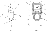
figure 1 depicts a perspective view of a variant of the closure device 1 according to the invention; -
figure 2 depicts an exploded view of the device offigure 1 ; -
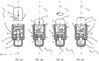
figure 3 depicts a section of the box-shaped body 2 of the device offigure 1 , containing the developingdirection 10 of the box-shaped body 2 itself; -
figures 4A-4D depict the closure sequence of the device 1, sectioned with a plane through the developingdirection 10 of the box-shaped body 2; -
figures 5A-5D depict the opening sequence of the device 1, sectioned with a plane through the developingdirection 10 of the box-shaped body 2. - With reference to the aforementioned figures, an executive variant of the closure device for gold, silver and costume jewellery items will be described, according to the invention, referred to in its entirety with the reference number 1.
- This closure device 1 comprises a female box-
shaped body 2 connected to a first end of a gold, silver and costume jewellery item by means of first hooking means 21. The box-shaped body 2 has engagement means with amale element 3 in turn connected to a second end of the gold, silver and costume jewellery item, by means of second hooking means. Such engagement means are adapted to mutually couple themale element 3 with the box-shaped body 2, so as to allow the mutual rotation of the box-shaped body 2 and of themale element 3 around the developingdirection 10 of the box-shaped body 2, between a closure position (fig. 4D ) and an opening position (fig. 5D ) of the closure device 1. - The box-
shaped body 2 has a portion shaped like a tubular element: in this way, in the closure position, themale element 3 is advantageously adapted to be inserted, at least partially, inside atubular element 4 defined in the box-shaped body 2. - As illustrated in
figure 3 , the engagement means compriseprojections 13 on the surface of an extreme portion 3 'of themale element 3, which is cylindrical so that it can engage with saidtubular element 4. - In the example set herein (
figures 1-5 ), theprojections 13 are three. - The
projections 13 are adapted to be engaged with guidingchannels 14 for therespective projection 13 which slides inside it (figures 4B-4C and5A-5C ). - The
channels 14 are defined on the surface of the box-shaped body 2. Each of thechannels 14 has afinal U-shaped part 14A and ending with a locking edge 14' for the projection 13 (figure 2 ). This locking edge 14' is in contrast with the thrusting action of the elastic means 8 in closure position. - Obviously, the
projections 13 are spaced from each other with the same pitch that separates the opening 14"of each channel 14 (fig. 2 ). - In the preferred solution, the elastic means consist of a compression spring 8 (
fig. 3 ), which constantly pushes themale element 3 in the developingdirection 10, so as to disengage it from the box-shaped body 2 (figure 4A-4D ). - It is therefore provided that the box-
shaped body 2 has aplunger 6 inside. Theplunger 6 has anabutment thickness 61 interposed between themale element 3 and thespring 8, so that, in the closure position of the device 1, themale element 3 exerts a pressure higher than the thrust of thespring 8. Moreover, theplunger 6 comprises aretainer element 62 for locking theplunger 6 itself to the box-shapedbody 2 when thespring 8 has the maximal extension in the opening position. - In order to operate the
plunger 6, thetubular element 4 has apassage hole 41 for the stem of the plunger 6 (fig. 3 and4 ). - In this embodiment variant, the box-shaped
body 2 comprises acover 5, arranged on the opposite side with respect to where themale element 3 engages with thebody 2, along the developingdirection 10. - With reference to
figures 4A-4D , to close the device 1, the user must first press themale element 3 on thespring 8 by means of theabutment thickness 61 and, once theprojections 13 have engaged therespective channels 14, the user will rotate themale element 3 on thetubular element 4 around thedirection 10 so that theprojections 13 travel thefinal part 14A of therelative channel 14 until reaching the locking edge 14' (in this case the rotation will be carried out in a counter-clockwise direction). - To open the device (
figures 5A-5D ), the user must first release theprojections 13 from the respective locking edges 14' by pressing thespring 8 and then rotating the male element from the opposite side (clockwise direction), i.e. in such a way that theprojections 13 travel thefinal part 14A of therelative channel 14 in the opposite direction, then moving away from the locking edge 14' and moving towards theinlet 14"of thechannel 14. Then, let the spring thrust themale element 3 disengaging it from the box-shapedbody 2. - From what has been described above it is therefore clear how the invention achieves the intended aim and objects and in particular it is underlined that a closure device is made for gold, silver and costume jewellery items, which is easy to open and close and which is very comfortable to use, as it is sufficient to exert a light pressure on the spring with the male element and apply a slight rotation, screwing or unscrewing, both when opening and closing the device.
- In particular, having thought to "imprison" the male element in the guiding channel during the closure of the device, allowed the realization of an extremely safe device, thus eliminating any risk of accidental opening.
- Another advantage of the invention is the fact that the technical limitations of this device are very limited and therefore it will be possible to produce a varied number of aesthetic variants, so as to allow the matching and compliance of the device on any type of jewel and in such a way as to make the closure device itself an aesthetically appreciable element of the jewel.
- Not least, the use of readily commercially available means and the use of common materials makes the device competitive in terms of cost.
- The so-designed invention is susceptible of numerous modifications and variations, all of which fall within the scope of the inventive concept.
- Further, all the details will be replaced by other technically equivalent elements.
- In practice, the materials employed, as well as the dimensions, may be different according to requirements, provided they are consistent with the realization purpose.
Claims (10)
- A closing device (1) for jewelry, goldsmith, silverware and costume jewelry, comprising:- a female-like box-shaped body (2) connected to a first end of an article of jewelry, goldsmith, silverware and costume jewelry by first hooking means (21), having engagement means (13, 14) with a male element (3) connected, in turn, to a second end of said article of jewelry, goldsmith, silverware and costume jewelry by means of second coupling means (31);- said engagement means (13, 14) being arranged to mutually couple said male element (3) with said box-shaped body (2);- in such a way as to allow mutual rotation of said box-shaped body (2) and of said male element (3) around the developing direction (10) of said box-shaped body (2);- between a closed position and an opening position of the closing device (1).
- Closing device according to claim 1, wherein, in the closed position, said male element (3) is arranged to be at least partially inserted inside a tubular element (4) defined in said box-shaped body (2).
- Closing device according to one or more of the preceding claims, wherein said engagement means (13, 14) comprise projections (13) on the surface of an extreme portion (3 ') of said male element (3) arranged to be of engagement with guiding means (14) defined on the surface of said box-shaped body (2).
- Closing device according to claim 2 and one or more of claims 3 and 4, wherein said extreme portion (3 ') of said male element (3) is cylindrical so that it is able to engage with said tubular element (4).
- Closing device according to one or more of claims 3, 4 and 5, wherein said projections (13) are in a number included between 3 and 5, extremes included.
- Closing device according to one or more of the preceding claims, comprising elastic means (8) for pushing said male element (3) in the developing direction (10), in order to disengage it from said box-shaped body (2).
- Closing device according to claims 3 and 6, wherein said guiding means (14) comprise sliding channels (14) for at least one of said projections (13), having a final part (14A) U shaped and ending with a locking edge (14 ') for said at least one of said projections (13), said locking edge (14') being in contrast with the pushing action of said elastic means (8) in the closed position.
- Closing device according to one or more of claims 6 and 7, comprising a plunger (6) positioned internally of said box-shaped body (2) and having a stroke thickness (61) interposed between said male element (3) and said elastic means (8), in such a way that, in the closed position, said male element (3) exerts a pressure higher than the thrust of said elastic means (8), said plunger (6) also comprising a stop element (62) in opening position.
- Closing device according to one or more of claims 2 and 4 and according to claim 8, wherein said tubular element (4) comprises, on its bottom, a passage hole (41) for said plunger (6).
- Closing device according to one or more of the preceding claims, wherein said box-like body (2) comprises a cover (5), positioned on the opposite side of the engagement with said male element (3) along the development direction (10) .
Applications Claiming Priority (1)
| Application Number | Priority Date | Filing Date | Title |
|---|---|---|---|
| IT201800001750A IT201800001750A1 (en) | 2018-01-24 | 2018-01-24 | LOCKING DEVICE FOR JEWELERY, GOLD, SILVER AND COSTUME JEWELERY |
Publications (2)
| Publication Number | Publication Date |
|---|---|
| EP3516981A1 true EP3516981A1 (en) | 2019-07-31 |
| EP3516981B1 EP3516981B1 (en) | 2023-05-10 |
Family
ID=62218054
Family Applications (1)
| Application Number | Title | Priority Date | Filing Date |
|---|---|---|---|
| EP19000037.2A Active EP3516981B1 (en) | 2018-01-24 | 2019-01-21 | Closure device for gold, silver and costume jewellery items |
Country Status (2)
| Country | Link |
|---|---|
| EP (1) | EP3516981B1 (en) |
| IT (1) | IT201800001750A1 (en) |
Cited By (2)
| Publication number | Priority date | Publication date | Assignee | Title |
|---|---|---|---|---|
| DE102020129694A1 (en) | 2020-08-19 | 2022-02-24 | Illya Zhus | Interlocking jewelry |
| CN117818244A (en) * | 2024-03-04 | 2024-04-05 | 庄银文化创意有限公司 | Lacquer silverware and manufacturing device thereof |
Citations (5)
| Publication number | Priority date | Publication date | Assignee | Title |
|---|---|---|---|---|
| FR2388520A1 (en) * | 1977-04-27 | 1978-11-24 | Pastor Perez Jose | Jewellery chain fastener assembly - has coil spring acting between telescopic tubular elements held closed by cooperating pin and groove |
| DE8700474U1 (en) * | 1987-01-10 | 1988-05-05 | Meinzer, Horst, 7530 Pforzheim | Bayonet clasp, especially for jewellery and pearl necklaces |
| EP1332690A2 (en) * | 2002-02-01 | 2003-08-06 | Masahiro Hoshino | Clasp and process for producing the same |
| US20080047111A1 (en) * | 2006-08-22 | 2008-02-28 | Garber Michael I | Clasp for chains and the like |
| US20170280836A1 (en) * | 2014-12-18 | 2017-10-05 | Wei Zhao | Switchable buckle jewelry lock catch with |
-
2018
- 2018-01-24 IT IT201800001750A patent/IT201800001750A1/en unknown
-
2019
- 2019-01-21 EP EP19000037.2A patent/EP3516981B1/en active Active
Patent Citations (5)
| Publication number | Priority date | Publication date | Assignee | Title |
|---|---|---|---|---|
| FR2388520A1 (en) * | 1977-04-27 | 1978-11-24 | Pastor Perez Jose | Jewellery chain fastener assembly - has coil spring acting between telescopic tubular elements held closed by cooperating pin and groove |
| DE8700474U1 (en) * | 1987-01-10 | 1988-05-05 | Meinzer, Horst, 7530 Pforzheim | Bayonet clasp, especially for jewellery and pearl necklaces |
| EP1332690A2 (en) * | 2002-02-01 | 2003-08-06 | Masahiro Hoshino | Clasp and process for producing the same |
| US20080047111A1 (en) * | 2006-08-22 | 2008-02-28 | Garber Michael I | Clasp for chains and the like |
| US20170280836A1 (en) * | 2014-12-18 | 2017-10-05 | Wei Zhao | Switchable buckle jewelry lock catch with |
Cited By (3)
| Publication number | Priority date | Publication date | Assignee | Title |
|---|---|---|---|---|
| DE102020129694A1 (en) | 2020-08-19 | 2022-02-24 | Illya Zhus | Interlocking jewelry |
| CN117818244A (en) * | 2024-03-04 | 2024-04-05 | 庄银文化创意有限公司 | Lacquer silverware and manufacturing device thereof |
| CN117818244B (en) * | 2024-03-04 | 2024-06-07 | 庄银文化创意有限公司 | Lacquer silverware and manufacturing device thereof |
Also Published As
| Publication number | Publication date |
|---|---|
| IT201800001750A1 (en) | 2019-07-24 |
| EP3516981B1 (en) | 2023-05-10 |
Similar Documents
| Publication | Publication Date | Title |
|---|---|---|
| US2986792A (en) | Clasp | |
| US3225565A (en) | Pearl slide shortener and pin adaptor | |
| US2585183A (en) | Jewelry | |
| JP5839498B2 (en) | Extensive clasps for bracelets, especially watch bands | |
| US4419874A (en) | Fastener device | |
| US3225406A (en) | Jewelry clasp | |
| US10722005B1 (en) | Jewelry clasp | |
| CN112515300B (en) | Chain with adjustable links for watches or jewellery | |
| US20160270490A1 (en) | Locking mechanism for jewelry | |
| US4425687A (en) | Safety clasp for jewelry | |
| EP3516981A1 (en) | Closure device for gold, silver and costume jewellery items | |
| US7210313B1 (en) | Release mechanism for a bangle | |
| US4562704A (en) | Jewelry clasp | |
| KR101577599B1 (en) | Clasp for accessory | |
| US2106540A (en) | Wrist watch band | |
| US2513592A (en) | Bracelet clasp | |
| US2947054A (en) | Earring clamp | |
| US20160183644A1 (en) | Jewelry Clasp | |
| US9516929B1 (en) | Fastening structure of jewellery | |
| US2215526A (en) | Clasp or connector for bracelets, chains, necklaces, or the like | |
| US20250255388A1 (en) | Jewelry link with spring closure | |
| US3848299A (en) | Jewelry clasp | |
| US4281441A (en) | Jewelry clasp | |
| US3350753A (en) | Necklace clasp | |
| EP4195973B1 (en) | Fastening device for jewellery |
Legal Events
| Date | Code | Title | Description |
|---|---|---|---|
| PUAI | Public reference made under article 153(3) epc to a published international application that has entered the european phase |
Free format text: ORIGINAL CODE: 0009012 |
|
| STAA | Information on the status of an ep patent application or granted ep patent |
Free format text: STATUS: THE APPLICATION HAS BEEN PUBLISHED |
|
| AK | Designated contracting states |
Kind code of ref document: A1 Designated state(s): AL AT BE BG CH CY CZ DE DK EE ES FI FR GB GR HR HU IE IS IT LI LT LU LV MC MK MT NL NO PL PT RO RS SE SI SK SM TR |
|
| AX | Request for extension of the european patent |
Extension state: BA ME |
|
| STAA | Information on the status of an ep patent application or granted ep patent |
Free format text: STATUS: REQUEST FOR EXAMINATION WAS MADE |
|
| 17P | Request for examination filed |
Effective date: 20200128 |
|
| RBV | Designated contracting states (corrected) |
Designated state(s): AL AT BE BG CH CY CZ DE DK EE ES FI FR GB GR HR HU IE IS IT LI LT LU LV MC MK MT NL NO PL PT RO RS SE SI SK SM TR |
|
| GRAP | Despatch of communication of intention to grant a patent |
Free format text: ORIGINAL CODE: EPIDOSNIGR1 |
|
| STAA | Information on the status of an ep patent application or granted ep patent |
Free format text: STATUS: GRANT OF PATENT IS INTENDED |
|
| INTG | Intention to grant announced |
Effective date: 20221128 |
|
| GRAS | Grant fee paid |
Free format text: ORIGINAL CODE: EPIDOSNIGR3 |
|
| GRAA | (expected) grant |
Free format text: ORIGINAL CODE: 0009210 |
|
| STAA | Information on the status of an ep patent application or granted ep patent |
Free format text: STATUS: THE PATENT HAS BEEN GRANTED |
|
| AK | Designated contracting states |
Kind code of ref document: B1 Designated state(s): AL AT BE BG CH CY CZ DE DK EE ES FI FR GB GR HR HU IE IS IT LI LT LU LV MC MK MT NL NO PL PT RO RS SE SI SK SM TR |
|
| REG | Reference to a national code |
Ref country code: GB Ref legal event code: FG4D |
|
| REG | Reference to a national code |
Ref country code: AT Ref legal event code: REF Ref document number: 1565865 Country of ref document: AT Kind code of ref document: T Effective date: 20230515 Ref country code: CH Ref legal event code: EP |
|
| REG | Reference to a national code |
Ref country code: DE Ref legal event code: R096 Ref document number: 602019028569 Country of ref document: DE |
|
| REG | Reference to a national code |
Ref country code: IE Ref legal event code: FG4D |
|
| REG | Reference to a national code |
Ref country code: LT Ref legal event code: MG9D |
|
| REG | Reference to a national code |
Ref country code: NL Ref legal event code: MP Effective date: 20230510 |
|
| REG | Reference to a national code |
Ref country code: AT Ref legal event code: MK05 Ref document number: 1565865 Country of ref document: AT Kind code of ref document: T Effective date: 20230510 |
|
| PG25 | Lapsed in a contracting state [announced via postgrant information from national office to epo] |
Ref country code: SE Free format text: LAPSE BECAUSE OF FAILURE TO SUBMIT A TRANSLATION OF THE DESCRIPTION OR TO PAY THE FEE WITHIN THE PRESCRIBED TIME-LIMIT Effective date: 20230510 Ref country code: PT Free format text: LAPSE BECAUSE OF FAILURE TO SUBMIT A TRANSLATION OF THE DESCRIPTION OR TO PAY THE FEE WITHIN THE PRESCRIBED TIME-LIMIT Effective date: 20230911 Ref country code: NO Free format text: LAPSE BECAUSE OF FAILURE TO SUBMIT A TRANSLATION OF THE DESCRIPTION OR TO PAY THE FEE WITHIN THE PRESCRIBED TIME-LIMIT Effective date: 20230810 Ref country code: NL Free format text: LAPSE BECAUSE OF FAILURE TO SUBMIT A TRANSLATION OF THE DESCRIPTION OR TO PAY THE FEE WITHIN THE PRESCRIBED TIME-LIMIT Effective date: 20230510 Ref country code: ES Free format text: LAPSE BECAUSE OF FAILURE TO SUBMIT A TRANSLATION OF THE DESCRIPTION OR TO PAY THE FEE WITHIN THE PRESCRIBED TIME-LIMIT Effective date: 20230510 Ref country code: AT Free format text: LAPSE BECAUSE OF FAILURE TO SUBMIT A TRANSLATION OF THE DESCRIPTION OR TO PAY THE FEE WITHIN THE PRESCRIBED TIME-LIMIT Effective date: 20230510 |
|
| PG25 | Lapsed in a contracting state [announced via postgrant information from national office to epo] |
Ref country code: RS Free format text: LAPSE BECAUSE OF FAILURE TO SUBMIT A TRANSLATION OF THE DESCRIPTION OR TO PAY THE FEE WITHIN THE PRESCRIBED TIME-LIMIT Effective date: 20230510 Ref country code: PL Free format text: LAPSE BECAUSE OF FAILURE TO SUBMIT A TRANSLATION OF THE DESCRIPTION OR TO PAY THE FEE WITHIN THE PRESCRIBED TIME-LIMIT Effective date: 20230510 Ref country code: LV Free format text: LAPSE BECAUSE OF FAILURE TO SUBMIT A TRANSLATION OF THE DESCRIPTION OR TO PAY THE FEE WITHIN THE PRESCRIBED TIME-LIMIT Effective date: 20230510 Ref country code: LT Free format text: LAPSE BECAUSE OF FAILURE TO SUBMIT A TRANSLATION OF THE DESCRIPTION OR TO PAY THE FEE WITHIN THE PRESCRIBED TIME-LIMIT Effective date: 20230510 Ref country code: IS Free format text: LAPSE BECAUSE OF FAILURE TO SUBMIT A TRANSLATION OF THE DESCRIPTION OR TO PAY THE FEE WITHIN THE PRESCRIBED TIME-LIMIT Effective date: 20230910 Ref country code: HR Free format text: LAPSE BECAUSE OF FAILURE TO SUBMIT A TRANSLATION OF THE DESCRIPTION OR TO PAY THE FEE WITHIN THE PRESCRIBED TIME-LIMIT Effective date: 20230510 Ref country code: GR Free format text: LAPSE BECAUSE OF FAILURE TO SUBMIT A TRANSLATION OF THE DESCRIPTION OR TO PAY THE FEE WITHIN THE PRESCRIBED TIME-LIMIT Effective date: 20230811 |
|
| PG25 | Lapsed in a contracting state [announced via postgrant information from national office to epo] |
Ref country code: FI Free format text: LAPSE BECAUSE OF FAILURE TO SUBMIT A TRANSLATION OF THE DESCRIPTION OR TO PAY THE FEE WITHIN THE PRESCRIBED TIME-LIMIT Effective date: 20230510 |
|
| P01 | Opt-out of the competence of the unified patent court (upc) registered |
Effective date: 20231123 |
|
| PG25 | Lapsed in a contracting state [announced via postgrant information from national office to epo] |
Ref country code: SK Free format text: LAPSE BECAUSE OF FAILURE TO SUBMIT A TRANSLATION OF THE DESCRIPTION OR TO PAY THE FEE WITHIN THE PRESCRIBED TIME-LIMIT Effective date: 20230510 |
|
| PG25 | Lapsed in a contracting state [announced via postgrant information from national office to epo] |
Ref country code: SM Free format text: LAPSE BECAUSE OF FAILURE TO SUBMIT A TRANSLATION OF THE DESCRIPTION OR TO PAY THE FEE WITHIN THE PRESCRIBED TIME-LIMIT Effective date: 20230510 Ref country code: SK Free format text: LAPSE BECAUSE OF FAILURE TO SUBMIT A TRANSLATION OF THE DESCRIPTION OR TO PAY THE FEE WITHIN THE PRESCRIBED TIME-LIMIT Effective date: 20230510 Ref country code: RO Free format text: LAPSE BECAUSE OF FAILURE TO SUBMIT A TRANSLATION OF THE DESCRIPTION OR TO PAY THE FEE WITHIN THE PRESCRIBED TIME-LIMIT Effective date: 20230510 Ref country code: EE Free format text: LAPSE BECAUSE OF FAILURE TO SUBMIT A TRANSLATION OF THE DESCRIPTION OR TO PAY THE FEE WITHIN THE PRESCRIBED TIME-LIMIT Effective date: 20230510 Ref country code: DK Free format text: LAPSE BECAUSE OF FAILURE TO SUBMIT A TRANSLATION OF THE DESCRIPTION OR TO PAY THE FEE WITHIN THE PRESCRIBED TIME-LIMIT Effective date: 20230510 Ref country code: CZ Free format text: LAPSE BECAUSE OF FAILURE TO SUBMIT A TRANSLATION OF THE DESCRIPTION OR TO PAY THE FEE WITHIN THE PRESCRIBED TIME-LIMIT Effective date: 20230510 |
|
| REG | Reference to a national code |
Ref country code: DE Ref legal event code: R097 Ref document number: 602019028569 Country of ref document: DE |
|
| PLBE | No opposition filed within time limit |
Free format text: ORIGINAL CODE: 0009261 |
|
| STAA | Information on the status of an ep patent application or granted ep patent |
Free format text: STATUS: NO OPPOSITION FILED WITHIN TIME LIMIT |
|
| 26N | No opposition filed |
Effective date: 20240213 |
|
| PG25 | Lapsed in a contracting state [announced via postgrant information from national office to epo] |
Ref country code: SI Free format text: LAPSE BECAUSE OF FAILURE TO SUBMIT A TRANSLATION OF THE DESCRIPTION OR TO PAY THE FEE WITHIN THE PRESCRIBED TIME-LIMIT Effective date: 20230510 |
|
| PG25 | Lapsed in a contracting state [announced via postgrant information from national office to epo] |
Ref country code: SI Free format text: LAPSE BECAUSE OF FAILURE TO SUBMIT A TRANSLATION OF THE DESCRIPTION OR TO PAY THE FEE WITHIN THE PRESCRIBED TIME-LIMIT Effective date: 20230510 |
|
| REG | Reference to a national code |
Ref country code: DE Ref legal event code: R119 Ref document number: 602019028569 Country of ref document: DE |
|
| PG25 | Lapsed in a contracting state [announced via postgrant information from national office to epo] |
Ref country code: MC Free format text: LAPSE BECAUSE OF FAILURE TO SUBMIT A TRANSLATION OF THE DESCRIPTION OR TO PAY THE FEE WITHIN THE PRESCRIBED TIME-LIMIT Effective date: 20230510 |
|
| PG25 | Lapsed in a contracting state [announced via postgrant information from national office to epo] |
Ref country code: MC Free format text: LAPSE BECAUSE OF FAILURE TO SUBMIT A TRANSLATION OF THE DESCRIPTION OR TO PAY THE FEE WITHIN THE PRESCRIBED TIME-LIMIT Effective date: 20230510 |
|
| REG | Reference to a national code |
Ref country code: CH Ref legal event code: PL |
|
| PG25 | Lapsed in a contracting state [announced via postgrant information from national office to epo] |
Ref country code: LU Free format text: LAPSE BECAUSE OF NON-PAYMENT OF DUE FEES Effective date: 20240121 |
|
| PG25 | Lapsed in a contracting state [announced via postgrant information from national office to epo] |
Ref country code: LU Free format text: LAPSE BECAUSE OF NON-PAYMENT OF DUE FEES Effective date: 20240121 |
|
| PG25 | Lapsed in a contracting state [announced via postgrant information from national office to epo] |
Ref country code: DE Free format text: LAPSE BECAUSE OF NON-PAYMENT OF DUE FEES Effective date: 20240801 |
|
| PG25 | Lapsed in a contracting state [announced via postgrant information from national office to epo] |
Ref country code: BE Free format text: LAPSE BECAUSE OF NON-PAYMENT OF DUE FEES Effective date: 20240131 |
|
| PG25 | Lapsed in a contracting state [announced via postgrant information from national office to epo] |
Ref country code: CH Free format text: LAPSE BECAUSE OF NON-PAYMENT OF DUE FEES Effective date: 20240131 |
|
| PG25 | Lapsed in a contracting state [announced via postgrant information from national office to epo] |
Ref country code: DE Free format text: LAPSE BECAUSE OF NON-PAYMENT OF DUE FEES Effective date: 20240801 Ref country code: CH Free format text: LAPSE BECAUSE OF NON-PAYMENT OF DUE FEES Effective date: 20240131 Ref country code: BE Free format text: LAPSE BECAUSE OF NON-PAYMENT OF DUE FEES Effective date: 20240131 |
|
| REG | Reference to a national code |
Ref country code: BE Ref legal event code: MM Effective date: 20240131 |
|
| PG25 | Lapsed in a contracting state [announced via postgrant information from national office to epo] |
Ref country code: BG Free format text: LAPSE BECAUSE OF FAILURE TO SUBMIT A TRANSLATION OF THE DESCRIPTION OR TO PAY THE FEE WITHIN THE PRESCRIBED TIME-LIMIT Effective date: 20230510 |
|
| PG25 | Lapsed in a contracting state [announced via postgrant information from national office to epo] |
Ref country code: BG Free format text: LAPSE BECAUSE OF FAILURE TO SUBMIT A TRANSLATION OF THE DESCRIPTION OR TO PAY THE FEE WITHIN THE PRESCRIBED TIME-LIMIT Effective date: 20230510 |
|
| PG25 | Lapsed in a contracting state [announced via postgrant information from national office to epo] |
Ref country code: IE Free format text: LAPSE BECAUSE OF NON-PAYMENT OF DUE FEES Effective date: 20240121 |
|
| PG25 | Lapsed in a contracting state [announced via postgrant information from national office to epo] |
Ref country code: IE Free format text: LAPSE BECAUSE OF NON-PAYMENT OF DUE FEES Effective date: 20240121 |
|
| PG25 | Lapsed in a contracting state [announced via postgrant information from national office to epo] |
Ref country code: CY Free format text: LAPSE BECAUSE OF FAILURE TO SUBMIT A TRANSLATION OF THE DESCRIPTION OR TO PAY THE FEE WITHIN THE PRESCRIBED TIME-LIMIT; INVALID AB INITIO Effective date: 20190121 |
|
| PG25 | Lapsed in a contracting state [announced via postgrant information from national office to epo] |
Ref country code: HU Free format text: LAPSE BECAUSE OF FAILURE TO SUBMIT A TRANSLATION OF THE DESCRIPTION OR TO PAY THE FEE WITHIN THE PRESCRIBED TIME-LIMIT; INVALID AB INITIO Effective date: 20190121 |
|
| PGFP | Annual fee paid to national office [announced via postgrant information from national office to epo] |
Ref country code: GB Payment date: 20260126 Year of fee payment: 8 |
|
| PGFP | Annual fee paid to national office [announced via postgrant information from national office to epo] |
Ref country code: IT Payment date: 20260128 Year of fee payment: 8 |
|
| PGFP | Annual fee paid to national office [announced via postgrant information from national office to epo] |
Ref country code: FR Payment date: 20260126 Year of fee payment: 8 |
|
| PGFP | Annual fee paid to national office [announced via postgrant information from national office to epo] |
Ref country code: TR Payment date: 20260112 Year of fee payment: 8 |