EP3516864B1 - Cabin for industrial vehicle comprising vision sensors - Google Patents
Cabin for industrial vehicle comprising vision sensors Download PDFInfo
- Publication number
- EP3516864B1 EP3516864B1 EP17788293.3A EP17788293A EP3516864B1 EP 3516864 B1 EP3516864 B1 EP 3516864B1 EP 17788293 A EP17788293 A EP 17788293A EP 3516864 B1 EP3516864 B1 EP 3516864B1
- Authority
- EP
- European Patent Office
- Prior art keywords
- cabin
- camera
- wall
- display unit
- space
- Prior art date
- Legal status (The legal status is an assumption and is not a legal conclusion. Google has not performed a legal analysis and makes no representation as to the accuracy of the status listed.)
- Active
Links
Images

Classifications
-
- B—PERFORMING OPERATIONS; TRANSPORTING
- B60—VEHICLES IN GENERAL
- B60R—VEHICLES, VEHICLE FITTINGS, OR VEHICLE PARTS, NOT OTHERWISE PROVIDED FOR
- B60R1/00—Optical viewing arrangements; Real-time viewing arrangements for drivers or passengers using optical image capturing systems, e.g. cameras or video systems specially adapted for use in or on vehicles
- B60R1/20—Real-time viewing arrangements for drivers or passengers using optical image capturing systems, e.g. cameras or video systems specially adapted for use in or on vehicles
- B60R1/22—Real-time viewing arrangements for drivers or passengers using optical image capturing systems, e.g. cameras or video systems specially adapted for use in or on vehicles for viewing an area outside the vehicle, e.g. the exterior of the vehicle
- B60R1/23—Real-time viewing arrangements for drivers or passengers using optical image capturing systems, e.g. cameras or video systems specially adapted for use in or on vehicles for viewing an area outside the vehicle, e.g. the exterior of the vehicle with a predetermined field of view
- B60R1/27—Real-time viewing arrangements for drivers or passengers using optical image capturing systems, e.g. cameras or video systems specially adapted for use in or on vehicles for viewing an area outside the vehicle, e.g. the exterior of the vehicle with a predetermined field of view providing all-round vision, e.g. using omnidirectional cameras
-
- H—ELECTRICITY
- H04—ELECTRIC COMMUNICATION TECHNIQUE
- H04N—PICTORIAL COMMUNICATION, e.g. TELEVISION
- H04N7/00—Television systems
- H04N7/18—Closed-circuit television [CCTV] systems, i.e. systems in which the video signal is not broadcast
- H04N7/181—Closed-circuit television [CCTV] systems, i.e. systems in which the video signal is not broadcast for receiving images from a plurality of remote sources
-
- B—PERFORMING OPERATIONS; TRANSPORTING
- B60—VEHICLES IN GENERAL
- B60R—VEHICLES, VEHICLE FITTINGS, OR VEHICLE PARTS, NOT OTHERWISE PROVIDED FOR
- B60R2300/00—Details of viewing arrangements using cameras and displays, specially adapted for use in a vehicle
- B60R2300/10—Details of viewing arrangements using cameras and displays, specially adapted for use in a vehicle characterised by the type of camera system used
- B60R2300/105—Details of viewing arrangements using cameras and displays, specially adapted for use in a vehicle characterised by the type of camera system used using multiple cameras
-
- B—PERFORMING OPERATIONS; TRANSPORTING
- B60—VEHICLES IN GENERAL
- B60R—VEHICLES, VEHICLE FITTINGS, OR VEHICLE PARTS, NOT OTHERWISE PROVIDED FOR
- B60R2300/00—Details of viewing arrangements using cameras and displays, specially adapted for use in a vehicle
- B60R2300/30—Details of viewing arrangements using cameras and displays, specially adapted for use in a vehicle characterised by the type of image processing
- B60R2300/303—Details of viewing arrangements using cameras and displays, specially adapted for use in a vehicle characterised by the type of image processing using joined images, e.g. multiple camera images
Definitions
- the present invention relates to a cabin for industrial vehicle comprising vision sensors.
- Cabins for industrial vehicles comprising vision sensors (normally TV cameras) carried by the cabin to film the space surrounding the industrial vehicle are already known.
- the video signal produced by the TV cameras being supplied to a monitor, housed in the cabin and showing the video signal produced by the TV cameras.
- the data shown by the monitor facilitate and improve driving the vehicle, especially during manoeuvres such as the reverse.
- the Italian patent application MI 2014A001114 describes a rear-view system for driving a vehicle in which three TV cameras arranged behind the vehicle include a left side TV camera, a central TV camera and a right rear TV camera.
- a longitudinally shaped display shows three horizontally adjacent projection areas corresponding to respective cameras shootings.
- US2005/0040939 A1 discloses a vehicle cabin according to the preamble of claim 1 and describes a plurality of TV cameras carried by a vehicle cabin and designed to film the space surrounding the vehicle and a monitor, housed in the cabin and electronically communicating with the TV cameras to show the video signals produced by the TV cameras.
- the object of the present invention is to provide a cabin comprising a vision system, which as fully as possible shows the space surrounding the vehicle.
- a cabin for industrial vehicle comprising a pair of side walls provided with doors, a base wall, an upper wall, a rear wall and a front wall housing a windscreen delimited by a lower edge and by an upper edge near the upper wall, a plurality of TV cameras carried by the cabin and filming the space surrounding the industrial vehicle and a monitor, housed in the cabin and electronically communicating with the TV cameras to show the video signal produced by the TV cameras, characterized in that the monitor has an elongated shape whose longer sides extend parallel to the upper edge of the windscreen near the upper wall; said monitor comprising a plurality of adjacent display units including: a central display unit; a first and a second side display units, arranged on opposite sides of the central display unit; a first and a second end display units, respectively arranged at the sides of the first and second side display units at the opposite ends of said monitor; said TV cameras comprising: a first front TV camera oriented with respect to said cabin so as to film a first portion of space
- Figure 1 indicates with the reference number 1 as a whole a cabin for industrial vehicle comprising a pair of side walls 2,3 provided with doors (not shown), a base wall 4, an upper wall 5, a rear wall 6 and a front wall 7 housing a windscreen 8 delimited by a lower edge 8-a ( Figure 2 ) and by an upper edge 8-b near the upper wall 5, a plurality of TV cameras 11 carried by the cabin 1 and filming the space surrounding the industrial vehicle and a first monitor 12 housed in the cabin 1 and electronically communicating with the TV cameras 11 to show the video signal produced by the TV cameras 11.
- the monitor 12 has an elongated rectangular shape with longer straight sides extending parallel to the upper edge 8-b of the windscreen 8 ( Figure 2 ) near the upper wall 5.
- the monitor 12 is connected to the upper wall 5 by means of support brackets of a known type that are not shown for simplicity's sake. Conveniently, the monitor 12 is a LED flat monitor.
- the monitor 12 comprises five adjacent rectangular display units 13 comprising:
- the TV cameras 11 are preferably digital and include:
- the industrial vehicle's driver sitting in the cabin 1 can see in a single display unit (monitor 12) the portion of space in front of the vehicle taken from three different positions (TV cameras 11-f1, 11-f2, 11-f3 with spaced axes) and the portion of space behind the vehicle taken from two different positions (TV cameras 11-p1 and 11-p with spaced axes). Therefore, the driver has a complete view of the space around the vehicle; this information facilitates and improves driving the vehicle, especially during manoeuvres.
- the axes h1, h2, h3 of the TV cameras 11-f1, 11-f2, 11-f3 are parallel to each other and evenly distributed along a horizontal plane and the axes h4, h5 of the TV cameras 11-p1, 11-p2 are parallel to each other and evenly distributed along a horizontal plane.
- the use of digital TV cameras allows varying the mutual spacing of the axes and the angle of inclination of the axes with respect to the horizontal based on the layout of the vehicle, of the trailer, the cabin configuration, etc.
- the second front TV camera 11-f2 and the first rear TV camera 11-p1 are carried by the support 20 of a front outer rear-view mirror, which extends towards the outside of the cabin 1 from a first side wall (wall 2).
- the third front TV camera 11-f3 and the second rear TV camera 11-p2 are carried by a support 21 of a second outer rear-view mirror, which extends towards the outside of the cabin from a second side wall (wall 3).
- a second monitor 24 and a third monitor 25, which extend in the cabin, one towards the other, from first and second sides (walls 2 and 3) of the cabin 1 near the lower edge 8-a of the windscreen 8.
- the TV cameras 11 further comprise a third rear TV camera 11p-3 carried by the rear wall 6 of the cabin 1 so as to film a sixth space portion 27 arranged behind the rear wall 6 and a fourth rear TV camera 11p-4 carried by the wall 6 so as to film a seventh portion 28 of the space arranged behind the rear wall 6.
- the axes h6, h7 of the TV cameras 11-p3, 11-p4 are parallel to each other and evenly distributed along a horizontal plane.
- the use of digital TV cameras allows varying the mutual spacing of the axes and the angle of inclination of the axes with respect to the horizontal based on the layout of the vehicle, of the trailer, the cabin configuration, etc.
- the angle between the axle and the vehicle can be modified to include longer or shorter trailers.
- the industrial vehicle's driver sitting in the cabin 1 can see in a pair of monitors arranged on opposite sides in the cabin the portion of space behind the vehicle taken from two different positions (TV cameras 11-p3 and 11-p4 with spaced axes). Therefore, the driver has a complete view of the space behind the vehicle; this information facilitates and improves driving the vehicle, especially during manoeuvres.
Landscapes
- Engineering & Computer Science (AREA)
- Multimedia (AREA)
- Mechanical Engineering (AREA)
- Signal Processing (AREA)
- Fittings On The Vehicle Exterior For Carrying Loads, And Devices For Holding Or Mounting Articles (AREA)
- Closed-Circuit Television Systems (AREA)
- Forklifts And Lifting Vehicles (AREA)
- Geophysics And Detection Of Objects (AREA)
Description
- The present invention relates to a cabin for industrial vehicle comprising vision sensors.
- Cabins for industrial vehicles comprising vision sensors (normally TV cameras) carried by the cabin to film the space surrounding the industrial vehicle are already known. The video signal produced by the TV cameras being supplied to a monitor, housed in the cabin and showing the video signal produced by the TV cameras. The data shown by the monitor facilitate and improve driving the vehicle, especially during manoeuvres such as the reverse.
- For example, the Italian patent application MI
2014A001114 -
US2005/0040939 A1 discloses a vehicle cabin according to the preamble of claim 1 and describes a plurality of TV cameras carried by a vehicle cabin and designed to film the space surrounding the vehicle and a monitor, housed in the cabin and electronically communicating with the TV cameras to show the video signals produced by the TV cameras. - The object of the present invention is to provide a cabin comprising a vision system, which as fully as possible shows the space surrounding the vehicle.
- This object is achieved by the present invention as it relates to a cabin for industrial vehicle comprising a pair of side walls provided with doors, a base wall, an upper wall, a rear wall and a front wall housing a windscreen delimited by a lower edge and by an upper edge near the upper wall, a plurality of TV cameras carried by the cabin and filming the space surrounding the industrial vehicle and a monitor, housed in the cabin and electronically communicating with the TV cameras to show the video signal produced by the TV cameras, characterized in that the monitor has an elongated shape whose longer sides extend parallel to the upper edge of the windscreen near the upper wall; said monitor comprising a plurality of adjacent display units including: a central display unit; a first and a second side display units, arranged on opposite sides of the central display unit; a first and a second end display units, respectively arranged at the sides of the first and second side display units at the opposite ends of said monitor; said TV cameras comprising: a first front TV camera oriented with respect to said cabin so as to film a first portion of space arranged in front of a central portion of said front wall; the video signal of said first front TV camera being sent to the central display unit; a second front TV camera oriented with respect to said cabin so as to film a second portion of space arranged in front of a first side of said front wall; the video signal of said second front TV camera being supplied to the first side display unit; a third front TV camera oriented with respect to said cabin so as to film a third portion of space arranged in front of a second side of said front wall; the video signal of said third front TV camera being supplied to the second side display unit; a first rear TV camera oriented with respect to said cabin so as to film a fourth portion of space arranged behind the second side of said front wall; the video signal of said first rear TV camera being supplied to the first end display unit; and a second rear TV camera oriented with respect to said cabin so as to film a fifth portion of space arranged behind the second side of said front wall; the video signal of said second rear TV camera being supplied to the second end display unit.
- The invention will now be illustrated with reference to the accompanying drawings, which schematically represent an example of the present invention, wherein:
- -
Figure 1 schematically shows a cabin comprising vision sensors according to the present invention; and -
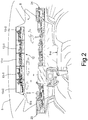
Figure 2 is a perspective view of the inside of the cabin. -
Figure 1 indicates with the reference number 1 as a whole a cabin for industrial vehicle comprising a pair ofside walls base wall 4, anupper wall 5, a rear wall 6 and afront wall 7 housing awindscreen 8 delimited by a lower edge 8-a (Figure 2 ) and by an upper edge 8-b near theupper wall 5, a plurality ofTV cameras 11 carried by the cabin 1 and filming the space surrounding the industrial vehicle and afirst monitor 12 housed in the cabin 1 and electronically communicating with theTV cameras 11 to show the video signal produced by theTV cameras 11. - The
monitor 12 has an elongated rectangular shape with longer straight sides extending parallel to the upper edge 8-b of the windscreen 8 (Figure 2 ) near theupper wall 5. Themonitor 12 is connected to theupper wall 5 by means of support brackets of a known type that are not shown for simplicity's sake. Conveniently, themonitor 12 is a LED flat monitor. - The
monitor 12 comprises five adjacentrectangular display units 13 comprising: - a central display unit 13-c;
- a first and a second side display units 13-11, 13-12 arranged on opposite sides of the central display unit 13-c;
- a first and a second end display unit 13-e1, 13-e2, respectively arranged at the sides of the first and second side displays 13-11, 13-12 at opposite ends of the
first monitor 12. - The
TV cameras 11 are preferably digital and include: - a first front TV camera 11-f1 oriented with respect to the cabin 1 so as to film a first portion of
space 14 arranged in front of a central portion of thefront wall 7; the video signal of said first front TV camera 11-f being supplied to the central display 13-c; - a second front TV camera 11-f2 oriented with respect to the cabin 1 so as to film a second portion of
space 15 arranged in front of a first side of thefront wall 7; the video signal of the second front TV camera 11-f2 being supplied to the first side display unit 13-11;
or a third front TV camera 11-f3 oriented with respect to the cabin 1 so as to film a third portion ofspace 16 arranged in front of a second side of thefront wall 7; the video signal of the third front TV camera 11-f3 being supplied to the second side display unit 13-12; - a first rear TV camera 11-p1 oriented with respect to the cabin 1 so as to film a fourth portion of
space 17 arranged behind the second side of thefront wall 7; the video signal of the first rear TV camera 11-p1 being supplied to the first end display unit 13-e1;
or a second rear TV camera 11-p2 oriented with respect to the cabin 1 so as to film a fifth portion ofspace 18 arranged behind the second side of thefront wall 7; the video signal of the second rear TV camera 11-p2 being supplied to the second end display unit 13-e2. - In this way, while driving the vehicle, the industrial vehicle's driver sitting in the cabin 1 (the driver's seat is indicated by S in
Figure 1 ) can see in a single display unit (monitor 12) the portion of space in front of the vehicle taken from three different positions (TV cameras 11-f1, 11-f2, 11-f3 with spaced axes) and the portion of space behind the vehicle taken from two different positions (TV cameras 11-p1 and 11-p with spaced axes). Therefore, the driver has a complete view of the space around the vehicle; this information facilitates and improves driving the vehicle, especially during manoeuvres. - In the example shown, the axes h1, h2, h3 of the TV cameras 11-f1, 11-f2, 11-f3 are parallel to each other and evenly distributed along a horizontal plane and the axes h4, h5 of the TV cameras 11-p1, 11-p2 are parallel to each other and evenly distributed along a horizontal plane.
- Alternatively, the use of digital TV cameras allows varying the mutual spacing of the axes and the angle of inclination of the axes with respect to the horizontal based on the layout of the vehicle, of the trailer, the cabin configuration, etc.
- The second front TV camera 11-f2 and the first rear TV camera 11-p1 are carried by the
support 20 of a front outer rear-view mirror, which extends towards the outside of the cabin 1 from a first side wall (wall 2). - The third front TV camera 11-f3 and the second rear TV camera 11-p2 are carried by a
support 21 of a second outer rear-view mirror, which extends towards the outside of the cabin from a second side wall (wall 3). - According to a further feature of the invention, it is provided a
second monitor 24 and athird monitor 25, which extend in the cabin, one towards the other, from first and second sides (walls 2 and 3) of the cabin 1 near the lower edge 8-a of thewindscreen 8. TheTV cameras 11 further comprise a third rear TV camera 11p-3 carried by the rear wall 6 of the cabin 1 so as to film asixth space portion 27 arranged behind the rear wall 6 and a fourth rear TV camera 11p-4 carried by the wall 6 so as to film aseventh portion 28 of the space arranged behind the rear wall 6. - In the shown example, the axes h6, h7 of the TV cameras 11-p3, 11-p4 are parallel to each other and evenly distributed along a horizontal plane.
- Alternatively, the use of digital TV cameras allows varying the mutual spacing of the axes and the angle of inclination of the axes with respect to the horizontal based on the layout of the vehicle, of the trailer, the cabin configuration, etc. In particular, the angle between the axle and the vehicle can be modified to include longer or shorter trailers.
- In this way, while driving the vehicle, the industrial vehicle's driver sitting in the cabin 1 can see in a pair of monitors arranged on opposite sides in the cabin the portion of space behind the vehicle taken from two different positions (TV cameras 11-p3 and 11-p4 with spaced axes). Therefore, the driver has a complete view of the space behind the vehicle; this information facilitates and improves driving the vehicle, especially during manoeuvres.
Claims (5)
- A cabin for industrial vehicle comprising a pair of side walls (2,3) provided with doors, a base wall (4), an upper wall (5), a rear wall (6) and a front wall (7) housing a windscreen (8) delimited by a lower edge (8-a) and by an upper edge (8-b) near the upper wall (5), a plurality of TV cameras (11) carried by the cabin to film the space surrounding the industrial vehicle and a monitor (12), housed in the cabin and electronically communicating with the TV cameras (11) to show the video signal produced by the TV cameras (11), said TV cameras (11) comprising (11):a first front TV camera (11-f) oriented with respect to said cabin so as to film a first portion of space (14) arranged in front of a central portion of said front wall;a first rear TV camera (11-p1) oriented with respect to said cabin so as to film a fourth portion of space (17) arranged behind the second side of said front wall;a second rear TV camera (11-p2) oriented with respect to said cabin so as to film a fifth portion of space (18) arranged behind the second side of said front wall;characterized in that the monitor (12) has an elongated shape whose longer sides extend parallel to the upper edge (8-b) of the windscreen near the upper wall;said monitor (12) comprising a plurality of adjacent display units comprising:a central display unit (13-c);a first and a second side display unit (13-11, 13-12) arranged on opposite sides of the central display unit (13-c) ;a first and a second end display unit (13-e1, 13-e2) respectively arranged beside the first and the second side display units at opposite ends of said monitor (12);a second front TV camera (11-f2) oriented with respect to said cabin so as to film a second portion of space (15) arranged in front of a first side of said front wall;a third front TV camera (11-f3) oriented with respect to said cabin so as to film a third portion of space (16) arranged in front of a second side of said front wall;wherein:• the video signal of said first front TV camera (11-f) is supplied to the central display unit (13-c),• the video signal of said first rear TV camera (11-p1) is supplied to the first end display unit (13-e1),• the video signal of said second rear TV camera (11-p2) is supplied to the second end display unit (13-e2),• the video signal of said second front TV camera (11-f2) being supplied to the first side display unit (13-11);and• the video signal of said third front TV camera (11-f3) being supplied to the second side display unit (13-12).
- A cabin according to claim 1, wherein the second front TV camera (11-f2) and the first rear TV camera (11-p1) are carried by the support (20) of a first outer rear-view mirror which extends towards the outside of the cabin (1) from a first side wall (2).
- A cabin according to claim 1 or 2, wherein the third front TV camera (11-f3) and the second rear TV camera (11-p2) are carried by the support (21) of a second outer rear-view mirror which extends towards the outside of the cabin from a second side wall (3).
- A cabin according to any one of the preceding claims, wherein a second and a third monitor (24, 25) are provided, which extend inside the cabin one towards the other from first and second sides of said cabin near a lower edge (8-a) of said windscreen; said TV cameras further comprising a third rear TV camera (11-p3) carried by said cabin so as to film a sixth portion of space (27) arranged behind the rear wall, and a fourth rear TV camera (11-p4) carried by said cabin so as to film a seventh portion of space (28) arranged behind the rear wall.
- A cabin according to any one of the preceding claims, wherein said display units have same shape and same size, for example a rectangular shape.
Applications Claiming Priority (2)
| Application Number | Priority Date | Filing Date | Title |
|---|---|---|---|
| IT102016000093818A IT201600093818A1 (en) | 2016-09-19 | 2016-09-19 | CABIN FOR INDUSTRIAL VEHICLE PROVIDED WITH VISION SENSORS |
| PCT/IB2017/055676 WO2018051321A1 (en) | 2016-09-19 | 2017-09-19 | Cabin for industrial vehicle comprising vision sensors |
Publications (2)
| Publication Number | Publication Date |
|---|---|
| EP3516864A1 EP3516864A1 (en) | 2019-07-31 |
| EP3516864B1 true EP3516864B1 (en) | 2020-12-30 |
Family
ID=57909892
Family Applications (1)
| Application Number | Title | Priority Date | Filing Date |
|---|---|---|---|
| EP17788293.3A Active EP3516864B1 (en) | 2016-09-19 | 2017-09-19 | Cabin for industrial vehicle comprising vision sensors |
Country Status (4)
| Country | Link |
|---|---|
| EP (1) | EP3516864B1 (en) |
| ES (1) | ES2862440T3 (en) |
| IT (1) | IT201600093818A1 (en) |
| WO (1) | WO2018051321A1 (en) |
Family Cites Families (5)
| Publication number | Priority date | Publication date | Assignee | Title |
|---|---|---|---|---|
| US7366595B1 (en) * | 1999-06-25 | 2008-04-29 | Seiko Epson Corporation | Vehicle drive assist system |
| JP3599639B2 (en) * | 2000-05-26 | 2004-12-08 | 松下電器産業株式会社 | Image processing device |
| GB2383315B (en) * | 2001-12-18 | 2005-04-06 | Christopher Donald Clarke | Vehicle imaging system |
| US20050040939A1 (en) * | 2003-08-21 | 2005-02-24 | Jobes Janard J. | Integrated motorcoach management system apparatus and method |
| EP2377725B2 (en) * | 2010-04-19 | 2017-01-25 | SMR Patents S.à.r.l. | Side mirror simulation |
-
2016
- 2016-09-19 IT IT102016000093818A patent/IT201600093818A1/en unknown
-
2017
- 2017-09-19 WO PCT/IB2017/055676 patent/WO2018051321A1/en not_active Ceased
- 2017-09-19 ES ES17788293T patent/ES2862440T3/en active Active
- 2017-09-19 EP EP17788293.3A patent/EP3516864B1/en active Active
Non-Patent Citations (1)
| Title |
|---|
| None * |
Also Published As
| Publication number | Publication date |
|---|---|
| WO2018051321A1 (en) | 2018-03-22 |
| IT201600093818A1 (en) | 2018-03-19 |
| ES2862440T3 (en) | 2021-10-07 |
| EP3516864A1 (en) | 2019-07-31 |
Similar Documents
| Publication | Publication Date | Title |
|---|---|---|
| US11318884B2 (en) | Video monitoring system for a motor vehicle | |
| EP2731828B1 (en) | Rearview imaging systems for vehicle | |
| EP3342645B1 (en) | Method for providing at least one information from an environmental region of a motor vehicle, display system for a motor vehicle driver assistance system for a motor vehicle as well as motor vehicle | |
| US20180141496A1 (en) | Method and device for displaying an image of the surroundings of a vehicle combination | |
| US8823796B2 (en) | Adaptive surrounding view monitoring apparatus and method thereof | |
| JP2015057341A (en) | Transportation vehicle visible system for displaying statutory visibility by main mirror and wide-angle mirror | |
| US20170116710A1 (en) | Merging of Partial Images to Form an Image of Surroundings of a Mode of Transport | |
| US20130096820A1 (en) | Virtual display system for a vehicle | |
| RU2017109089A (en) | Vehicle Communication System | |
| US10618469B2 (en) | Systems and methods for the representation of a rear outer region of a vehicle | |
| CA2667105A1 (en) | Device for enlarging the field of vision | |
| CN105539286A (en) | Method and device to support driver of vehicle combination, in particular commercial vehicle combination | |
| CN101585347A (en) | Rear view system for automobile and automobile therewith | |
| JP6443247B2 (en) | Vehicle display device | |
| JP2005534246A5 (en) | ||
| WO2015013311A1 (en) | Vehicle imaging system | |
| CN104608695A (en) | Vehicle-mounted electronic rearview mirror head-up displaying device | |
| EP3516864B1 (en) | Cabin for industrial vehicle comprising vision sensors | |
| US9067538B2 (en) | Drive assist display apparatus | |
| US20210162922A1 (en) | Vehicle imaging system | |
| JP2016060411A (en) | Confirmation assist device and confirmation assist system | |
| WO2019064126A1 (en) | System and method for assisting parallel parking using orthogonal projection | |
| JP2015106777A (en) | Image processing apparatus, driving support apparatus, navigation apparatus, and camera apparatus | |
| CN102233853B (en) | Mounting system for confusion-proof mounting of automotive exterior rear view mirrors | |
| JP6672565B2 (en) | Display device |
Legal Events
| Date | Code | Title | Description |
|---|---|---|---|
| STAA | Information on the status of an ep patent application or granted ep patent |
Free format text: STATUS: UNKNOWN |
|
| STAA | Information on the status of an ep patent application or granted ep patent |
Free format text: STATUS: THE INTERNATIONAL PUBLICATION HAS BEEN MADE |
|
| PUAI | Public reference made under article 153(3) epc to a published international application that has entered the european phase |
Free format text: ORIGINAL CODE: 0009012 |
|
| STAA | Information on the status of an ep patent application or granted ep patent |
Free format text: STATUS: REQUEST FOR EXAMINATION WAS MADE |
|
| 17P | Request for examination filed |
Effective date: 20190313 |
|
| AK | Designated contracting states |
Kind code of ref document: A1 Designated state(s): AL AT BE BG CH CY CZ DE DK EE ES FI FR GB GR HR HU IE IS IT LI LT LU LV MC MK MT NL NO PL PT RO RS SE SI SK SM TR |
|
| AX | Request for extension of the european patent |
Extension state: BA ME |
|
| DAV | Request for validation of the european patent (deleted) | ||
| DAX | Request for extension of the european patent (deleted) | ||
| GRAP | Despatch of communication of intention to grant a patent |
Free format text: ORIGINAL CODE: EPIDOSNIGR1 |
|
| STAA | Information on the status of an ep patent application or granted ep patent |
Free format text: STATUS: GRANT OF PATENT IS INTENDED |
|
| RIC1 | Information provided on ipc code assigned before grant |
Ipc: H04N 7/18 20060101AFI20200515BHEP Ipc: B60R 1/00 20060101ALI20200515BHEP |
|
| INTG | Intention to grant announced |
Effective date: 20200616 |
|
| GRAJ | Information related to disapproval of communication of intention to grant by the applicant or resumption of examination proceedings by the epo deleted |
Free format text: ORIGINAL CODE: EPIDOSDIGR1 |
|
| STAA | Information on the status of an ep patent application or granted ep patent |
Free format text: STATUS: REQUEST FOR EXAMINATION WAS MADE |
|
| INTC | Intention to grant announced (deleted) | ||
| GRAR | Information related to intention to grant a patent recorded |
Free format text: ORIGINAL CODE: EPIDOSNIGR71 |
|
| GRAS | Grant fee paid |
Free format text: ORIGINAL CODE: EPIDOSNIGR3 |
|
| STAA | Information on the status of an ep patent application or granted ep patent |
Free format text: STATUS: GRANT OF PATENT IS INTENDED |
|
| GRAA | (expected) grant |
Free format text: ORIGINAL CODE: 0009210 |
|
| STAA | Information on the status of an ep patent application or granted ep patent |
Free format text: STATUS: THE PATENT HAS BEEN GRANTED |
|
| INTG | Intention to grant announced |
Effective date: 20201119 |
|
| AK | Designated contracting states |
Kind code of ref document: B1 Designated state(s): AL AT BE BG CH CY CZ DE DK EE ES FI FR GB GR HR HU IE IS IT LI LT LU LV MC MK MT NL NO PL PT RO RS SE SI SK SM TR |
|
| REG | Reference to a national code |
Ref country code: GB Ref legal event code: FG4D |
|
| REG | Reference to a national code |
Ref country code: AT Ref legal event code: REF Ref document number: 1351122 Country of ref document: AT Kind code of ref document: T Effective date: 20210115 |
|
| REG | Reference to a national code |
Ref country code: DE Ref legal event code: R096 Ref document number: 602017030567 Country of ref document: DE |
|
| REG | Reference to a national code |
Ref country code: IE Ref legal event code: FG4D |
|
| PG25 | Lapsed in a contracting state [announced via postgrant information from national office to epo] |
Ref country code: GR Free format text: LAPSE BECAUSE OF FAILURE TO SUBMIT A TRANSLATION OF THE DESCRIPTION OR TO PAY THE FEE WITHIN THE PRESCRIBED TIME-LIMIT Effective date: 20210331 Ref country code: NO Free format text: LAPSE BECAUSE OF FAILURE TO SUBMIT A TRANSLATION OF THE DESCRIPTION OR TO PAY THE FEE WITHIN THE PRESCRIBED TIME-LIMIT Effective date: 20210330 Ref country code: FI Free format text: LAPSE BECAUSE OF FAILURE TO SUBMIT A TRANSLATION OF THE DESCRIPTION OR TO PAY THE FEE WITHIN THE PRESCRIBED TIME-LIMIT Effective date: 20201230 Ref country code: RS Free format text: LAPSE BECAUSE OF FAILURE TO SUBMIT A TRANSLATION OF THE DESCRIPTION OR TO PAY THE FEE WITHIN THE PRESCRIBED TIME-LIMIT Effective date: 20201230 |
|
| REG | Reference to a national code |
Ref country code: AT Ref legal event code: MK05 Ref document number: 1351122 Country of ref document: AT Kind code of ref document: T Effective date: 20201230 |
|
| PG25 | Lapsed in a contracting state [announced via postgrant information from national office to epo] |
Ref country code: BG Free format text: LAPSE BECAUSE OF FAILURE TO SUBMIT A TRANSLATION OF THE DESCRIPTION OR TO PAY THE FEE WITHIN THE PRESCRIBED TIME-LIMIT Effective date: 20210330 Ref country code: SE Free format text: LAPSE BECAUSE OF FAILURE TO SUBMIT A TRANSLATION OF THE DESCRIPTION OR TO PAY THE FEE WITHIN THE PRESCRIBED TIME-LIMIT Effective date: 20201230 Ref country code: LV Free format text: LAPSE BECAUSE OF FAILURE TO SUBMIT A TRANSLATION OF THE DESCRIPTION OR TO PAY THE FEE WITHIN THE PRESCRIBED TIME-LIMIT Effective date: 20201230 |
|
| REG | Reference to a national code |
Ref country code: NL Ref legal event code: MP Effective date: 20201230 |
|
| PG25 | Lapsed in a contracting state [announced via postgrant information from national office to epo] |
Ref country code: HR Free format text: LAPSE BECAUSE OF FAILURE TO SUBMIT A TRANSLATION OF THE DESCRIPTION OR TO PAY THE FEE WITHIN THE PRESCRIBED TIME-LIMIT Effective date: 20201230 |
|
| REG | Reference to a national code |
Ref country code: LT Ref legal event code: MG9D |
|
| PG25 | Lapsed in a contracting state [announced via postgrant information from national office to epo] |
Ref country code: SK Free format text: LAPSE BECAUSE OF FAILURE TO SUBMIT A TRANSLATION OF THE DESCRIPTION OR TO PAY THE FEE WITHIN THE PRESCRIBED TIME-LIMIT Effective date: 20201230 Ref country code: PT Free format text: LAPSE BECAUSE OF FAILURE TO SUBMIT A TRANSLATION OF THE DESCRIPTION OR TO PAY THE FEE WITHIN THE PRESCRIBED TIME-LIMIT Effective date: 20210430 Ref country code: RO Free format text: LAPSE BECAUSE OF FAILURE TO SUBMIT A TRANSLATION OF THE DESCRIPTION OR TO PAY THE FEE WITHIN THE PRESCRIBED TIME-LIMIT Effective date: 20201230 Ref country code: EE Free format text: LAPSE BECAUSE OF FAILURE TO SUBMIT A TRANSLATION OF THE DESCRIPTION OR TO PAY THE FEE WITHIN THE PRESCRIBED TIME-LIMIT Effective date: 20201230 Ref country code: CZ Free format text: LAPSE BECAUSE OF FAILURE TO SUBMIT A TRANSLATION OF THE DESCRIPTION OR TO PAY THE FEE WITHIN THE PRESCRIBED TIME-LIMIT Effective date: 20201230 Ref country code: LT Free format text: LAPSE BECAUSE OF FAILURE TO SUBMIT A TRANSLATION OF THE DESCRIPTION OR TO PAY THE FEE WITHIN THE PRESCRIBED TIME-LIMIT Effective date: 20201230 |
|
| PG25 | Lapsed in a contracting state [announced via postgrant information from national office to epo] |
Ref country code: PL Free format text: LAPSE BECAUSE OF FAILURE TO SUBMIT A TRANSLATION OF THE DESCRIPTION OR TO PAY THE FEE WITHIN THE PRESCRIBED TIME-LIMIT Effective date: 20201230 Ref country code: AT Free format text: LAPSE BECAUSE OF FAILURE TO SUBMIT A TRANSLATION OF THE DESCRIPTION OR TO PAY THE FEE WITHIN THE PRESCRIBED TIME-LIMIT Effective date: 20201230 |
|
| PG25 | Lapsed in a contracting state [announced via postgrant information from national office to epo] |
Ref country code: IS Free format text: LAPSE BECAUSE OF FAILURE TO SUBMIT A TRANSLATION OF THE DESCRIPTION OR TO PAY THE FEE WITHIN THE PRESCRIBED TIME-LIMIT Effective date: 20210430 |
|
| REG | Reference to a national code |
Ref country code: DE Ref legal event code: R097 Ref document number: 602017030567 Country of ref document: DE |
|
| REG | Reference to a national code |
Ref country code: ES Ref legal event code: FG2A Ref document number: 2862440 Country of ref document: ES Kind code of ref document: T3 Effective date: 20211007 |
|
| PG25 | Lapsed in a contracting state [announced via postgrant information from national office to epo] |
Ref country code: AL Free format text: LAPSE BECAUSE OF FAILURE TO SUBMIT A TRANSLATION OF THE DESCRIPTION OR TO PAY THE FEE WITHIN THE PRESCRIBED TIME-LIMIT Effective date: 20201230 |
|
| PLBE | No opposition filed within time limit |
Free format text: ORIGINAL CODE: 0009261 |
|
| STAA | Information on the status of an ep patent application or granted ep patent |
Free format text: STATUS: NO OPPOSITION FILED WITHIN TIME LIMIT |
|
| PG25 | Lapsed in a contracting state [announced via postgrant information from national office to epo] |
Ref country code: DK Free format text: LAPSE BECAUSE OF FAILURE TO SUBMIT A TRANSLATION OF THE DESCRIPTION OR TO PAY THE FEE WITHIN THE PRESCRIBED TIME-LIMIT Effective date: 20201230 |
|
| 26N | No opposition filed |
Effective date: 20211001 |
|
| PG25 | Lapsed in a contracting state [announced via postgrant information from national office to epo] |
Ref country code: SI Free format text: LAPSE BECAUSE OF FAILURE TO SUBMIT A TRANSLATION OF THE DESCRIPTION OR TO PAY THE FEE WITHIN THE PRESCRIBED TIME-LIMIT Effective date: 20201230 |
|
| REG | Reference to a national code |
Ref country code: CH Ref legal event code: PL |
|
| REG | Reference to a national code |
Ref country code: BE Ref legal event code: MM Effective date: 20210930 |
|
| PG25 | Lapsed in a contracting state [announced via postgrant information from national office to epo] |
Ref country code: IS Free format text: LAPSE BECAUSE OF FAILURE TO SUBMIT A TRANSLATION OF THE DESCRIPTION OR TO PAY THE FEE WITHIN THE PRESCRIBED TIME-LIMIT Effective date: 20210430 Ref country code: MC Free format text: LAPSE BECAUSE OF FAILURE TO SUBMIT A TRANSLATION OF THE DESCRIPTION OR TO PAY THE FEE WITHIN THE PRESCRIBED TIME-LIMIT Effective date: 20201230 |
|
| PG25 | Lapsed in a contracting state [announced via postgrant information from national office to epo] |
Ref country code: LU Free format text: LAPSE BECAUSE OF NON-PAYMENT OF DUE FEES Effective date: 20210919 Ref country code: IE Free format text: LAPSE BECAUSE OF NON-PAYMENT OF DUE FEES Effective date: 20210919 Ref country code: BE Free format text: LAPSE BECAUSE OF NON-PAYMENT OF DUE FEES Effective date: 20210930 |
|
| PG25 | Lapsed in a contracting state [announced via postgrant information from national office to epo] |
Ref country code: LI Free format text: LAPSE BECAUSE OF NON-PAYMENT OF DUE FEES Effective date: 20210930 Ref country code: CH Free format text: LAPSE BECAUSE OF NON-PAYMENT OF DUE FEES Effective date: 20210930 |
|
| P01 | Opt-out of the competence of the unified patent court (upc) registered |
Effective date: 20230523 |
|
| PG25 | Lapsed in a contracting state [announced via postgrant information from national office to epo] |
Ref country code: NL Free format text: LAPSE BECAUSE OF NON-PAYMENT OF DUE FEES Effective date: 20201230 Ref country code: CY Free format text: LAPSE BECAUSE OF FAILURE TO SUBMIT A TRANSLATION OF THE DESCRIPTION OR TO PAY THE FEE WITHIN THE PRESCRIBED TIME-LIMIT Effective date: 20201230 |
|
| PG25 | Lapsed in a contracting state [announced via postgrant information from national office to epo] |
Ref country code: SM Free format text: LAPSE BECAUSE OF FAILURE TO SUBMIT A TRANSLATION OF THE DESCRIPTION OR TO PAY THE FEE WITHIN THE PRESCRIBED TIME-LIMIT Effective date: 20201230 Ref country code: HU Free format text: LAPSE BECAUSE OF FAILURE TO SUBMIT A TRANSLATION OF THE DESCRIPTION OR TO PAY THE FEE WITHIN THE PRESCRIBED TIME-LIMIT; INVALID AB INITIO Effective date: 20170919 |
|
| PG25 | Lapsed in a contracting state [announced via postgrant information from national office to epo] |
Ref country code: MK Free format text: LAPSE BECAUSE OF FAILURE TO SUBMIT A TRANSLATION OF THE DESCRIPTION OR TO PAY THE FEE WITHIN THE PRESCRIBED TIME-LIMIT Effective date: 20201230 |
|
| PG25 | Lapsed in a contracting state [announced via postgrant information from national office to epo] |
Ref country code: TR Free format text: LAPSE BECAUSE OF FAILURE TO SUBMIT A TRANSLATION OF THE DESCRIPTION OR TO PAY THE FEE WITHIN THE PRESCRIBED TIME-LIMIT Effective date: 20201230 |
|
| PG25 | Lapsed in a contracting state [announced via postgrant information from national office to epo] |
Ref country code: MT Free format text: LAPSE BECAUSE OF FAILURE TO SUBMIT A TRANSLATION OF THE DESCRIPTION OR TO PAY THE FEE WITHIN THE PRESCRIBED TIME-LIMIT Effective date: 20201230 |
|
| PGFP | Annual fee paid to national office [announced via postgrant information from national office to epo] |
Ref country code: DE Payment date: 20250926 Year of fee payment: 9 |
|
| PGFP | Annual fee paid to national office [announced via postgrant information from national office to epo] |
Ref country code: IT Payment date: 20250909 Year of fee payment: 9 |
|
| PGFP | Annual fee paid to national office [announced via postgrant information from national office to epo] |
Ref country code: GB Payment date: 20250923 Year of fee payment: 9 |
|
| PGFP | Annual fee paid to national office [announced via postgrant information from national office to epo] |
Ref country code: FR Payment date: 20250925 Year of fee payment: 9 |
|
| PGFP | Annual fee paid to national office [announced via postgrant information from national office to epo] |
Ref country code: ES Payment date: 20251015 Year of fee payment: 9 |