EP3516794B1 - Procédé permettant une discrimination de communications montantes ou descendantes - Google Patents
Procédé permettant une discrimination de communications montantes ou descendantes Download PDFInfo
- Publication number
- EP3516794B1 EP3516794B1 EP17772414.3A EP17772414A EP3516794B1 EP 3516794 B1 EP3516794 B1 EP 3516794B1 EP 17772414 A EP17772414 A EP 17772414A EP 3516794 B1 EP3516794 B1 EP 3516794B1
- Authority
- EP
- European Patent Office
- Prior art keywords
- preamble
- packet
- control station
- uplink
- downlink
- Prior art date
- Legal status (The legal status is an assumption and is not a legal conclusion. Google has not performed a legal analysis and makes no representation as to the accuracy of the status listed.)
- Active
Links
- 238000004891 communication Methods 0.000 title claims description 104
- 238000000034 method Methods 0.000 title claims description 55
- 230000005540 biological transmission Effects 0.000 claims description 33
- 238000004364 calculation method Methods 0.000 claims description 9
- 238000004590 computer program Methods 0.000 claims description 6
- 230000004044 response Effects 0.000 claims description 3
- 238000003780 insertion Methods 0.000 claims description 2
- 230000037431 insertion Effects 0.000 claims description 2
- 238000012545 processing Methods 0.000 description 48
- 241000985719 Antennariidae Species 0.000 description 10
- 230000000630 rising effect Effects 0.000 description 10
- 230000015572 biosynthetic process Effects 0.000 description 4
- 230000008569 process Effects 0.000 description 4
- 230000017105 transposition Effects 0.000 description 4
- 238000001914 filtration Methods 0.000 description 3
- 230000006870 function Effects 0.000 description 3
- 230000033764 rhythmic process Effects 0.000 description 3
- 230000002123 temporal effect Effects 0.000 description 3
- 238000012549 training Methods 0.000 description 3
- 241000282414 Homo sapiens Species 0.000 description 2
- 238000006073 displacement reaction Methods 0.000 description 2
- 238000005096 rolling process Methods 0.000 description 2
- 238000010187 selection method Methods 0.000 description 2
- 238000001228 spectrum Methods 0.000 description 2
- 241000282412 Homo Species 0.000 description 1
- 230000003321 amplification Effects 0.000 description 1
- 230000004907 flux Effects 0.000 description 1
- 238000005259 measurement Methods 0.000 description 1
- 230000003446 memory effect Effects 0.000 description 1
- 238000003199 nucleic acid amplification method Methods 0.000 description 1
- 230000008520 organization Effects 0.000 description 1
- 238000004321 preservation Methods 0.000 description 1
- 230000035484 reaction time Effects 0.000 description 1
- 230000001360 synchronised effect Effects 0.000 description 1
- 238000011144 upstream manufacturing Methods 0.000 description 1
Images

Classifications
-
- H—ELECTRICITY
- H04—ELECTRIC COMMUNICATION TECHNIQUE
- H04B—TRANSMISSION
- H04B7/00—Radio transmission systems, i.e. using radiation field
- H04B7/24—Radio transmission systems, i.e. using radiation field for communication between two or more posts
- H04B7/26—Radio transmission systems, i.e. using radiation field for communication between two or more posts at least one of which is mobile
- H04B7/2643—Radio transmission systems, i.e. using radiation field for communication between two or more posts at least one of which is mobile using time-division multiple access [TDMA]
- H04B7/2656—Radio transmission systems, i.e. using radiation field for communication between two or more posts at least one of which is mobile using time-division multiple access [TDMA] for structure of frame, burst
-
- H—ELECTRICITY
- H04—ELECTRIC COMMUNICATION TECHNIQUE
- H04L—TRANSMISSION OF DIGITAL INFORMATION, e.g. TELEGRAPHIC COMMUNICATION
- H04L25/00—Baseband systems
- H04L25/02—Details ; arrangements for supplying electrical power along data transmission lines
- H04L25/0202—Channel estimation
-
- H—ELECTRICITY
- H04—ELECTRIC COMMUNICATION TECHNIQUE
- H04L—TRANSMISSION OF DIGITAL INFORMATION, e.g. TELEGRAPHIC COMMUNICATION
- H04L5/00—Arrangements affording multiple use of the transmission path
- H04L5/003—Arrangements for allocating sub-channels of the transmission path
- H04L5/0053—Allocation of signaling, i.e. of overhead other than pilot signals
-
- H—ELECTRICITY
- H04—ELECTRIC COMMUNICATION TECHNIQUE
- H04W—WIRELESS COMMUNICATION NETWORKS
- H04W72/00—Local resource management
- H04W72/04—Wireless resource allocation
- H04W72/044—Wireless resource allocation based on the type of the allocated resource
- H04W72/0446—Resources in time domain, e.g. slots or frames
-
- H—ELECTRICITY
- H04—ELECTRIC COMMUNICATION TECHNIQUE
- H04W—WIRELESS COMMUNICATION NETWORKS
- H04W72/00—Local resource management
- H04W72/20—Control channels or signalling for resource management
-
- B—PERFORMING OPERATIONS; TRANSPORTING
- B64—AIRCRAFT; AVIATION; COSMONAUTICS
- B64U—UNMANNED AERIAL VEHICLES [UAV]; EQUIPMENT THEREFOR
- B64U10/00—Type of UAV
- B64U10/10—Rotorcrafts
- B64U10/13—Flying platforms
- B64U10/14—Flying platforms with four distinct rotor axes, e.g. quadcopters
-
- B—PERFORMING OPERATIONS; TRANSPORTING
- B64—AIRCRAFT; AVIATION; COSMONAUTICS
- B64U—UNMANNED AERIAL VEHICLES [UAV]; EQUIPMENT THEREFOR
- B64U2101/00—UAVs specially adapted for particular uses or applications
- B64U2101/30—UAVs specially adapted for particular uses or applications for imaging, photography or videography
-
- B—PERFORMING OPERATIONS; TRANSPORTING
- B64—AIRCRAFT; AVIATION; COSMONAUTICS
- B64U—UNMANNED AERIAL VEHICLES [UAV]; EQUIPMENT THEREFOR
- B64U2201/00—UAVs characterised by their flight controls
- B64U2201/20—Remote controls
-
- H—ELECTRICITY
- H04—ELECTRIC COMMUNICATION TECHNIQUE
- H04B—TRANSMISSION
- H04B7/00—Radio transmission systems, i.e. using radiation field
- H04B7/14—Relay systems
- H04B7/15—Active relay systems
- H04B7/185—Space-based or airborne stations; Stations for satellite systems
- H04B7/18502—Airborne stations
- H04B7/18506—Communications with or from aircraft, i.e. aeronautical mobile service
Definitions
- the invention relates to a method implemented in a system of unmanned mobile devices comprising a control station and at least one unmanned mobile device allowing discrimination of uplink communications from the control station to an unmanned or downlink mobile device. '' an unmanned mobile device to the control station.
- unmanned mobile devices Although some unmanned mobile devices are fully automatic, many of these devices are remotely controlled by one or more humans from a command station. These unmanned mobile devices must generally transmit observation results either to a person who orders them, or to a person responsible for analyzing data resulting from these observations. This data frequently includes images and sometimes videos. It is then necessary to establish wireless communications between the unmanned mobile devices and the control station to ensure remote control of said devices and transmission of observation data. Such communications must be as reliable as possible so that, on the one hand, a loss of control does not lead to the loss of an unmanned mobile device that can be very expensive, and on the other hand, so that the observation data are as usable as possible.
- unmanned mobile device systems comprising a plurality of unmanned mobile devices and at least one control station.
- uplink communications going from the command station to an unmanned mobile device
- downlink communications going from a drone to the command station. It is important for an unmanned mobile device to be able to quickly identify the uplink communications which may concern it, downlink communications which originate from another unmanned mobile device and therefore generally do not concern it. It is also important for a command station to be able to quickly identify downlink communications which may concern it, uplink communications which may originate from another command station and therefore do not concern it.
- the document WO 2015/043123 A1 describes a method for improving data communication between communication terminals and providing robust uplink data transmission and broadband downlink data transmission while avoiding interference between uplink data transmission and downlink transmission.
- the document EP 1 045 533 A1 describes a communication system making it possible to transmit and receive blocks of data and making it possible to distinguish different types of blocks of data and to distinguish in particular blocks of rising data from blocks of falling data.
- the present invention relates to a method implemented in a system of unmanned mobile devices comprising a control station and at least one unmanned mobile device, the control station communicating with each unmanned mobile device using a time-division multiple access type medium access technique in which each communication takes place in frames.
- Each frame is divided into a plurality of time intervals, each interval being divided into a plurality of subintervals, each subinterval being divided into a plurality of periods for transmitting data in the form of data packets, each packet of data being modulated by a predefined modulation before its transmission, a first period of the plurality of periods making it possible to transmit a preamble allowing a receiver of said preamble to make a channel estimate in order to carry out frequency, phase, rhythm and time synchronizations. receive signal equalizations, said preamble being further used for identify the uplink communications of the downlink communications, and a second period for transmitting a block of data.
- the method comprises: using in each uplink communication from the control station to a mobile device without pilots, a preamble, said uplink preamble, orthogonal to the preamble, said down preamble, used in each downlink communication from a mobile unmanned device command station; and, upon reception of a modulated data packet, determining whether said packet has been transmitted in the context of an uplink or downlink communication as a function of a result of a convolution between said packet with a reference preamble modulated according to the predefined modulation, said reference preamble corresponding to the rising preamble or the descending preamble.
- a receiver of a data packet is able to determine whether said packet has been transmitted in the context of an uplink or downlink communication without having to demodulate said packet.
- the packet can then easily be rejected by the receiver, if said receiver is not affected by said packet.
- This method of discriminating packets transmitted in the context of an uplink or downlink communication therefore has a low computational cost.
- a correlation value greater than or equal to a first predefined threshold is obtained, said packet is considered to have been transmitted in the context of '' a downlink communication, and when during a convolution calculation between said packet and the modulated rising preamble, a correlation value greater than or equal to a second predefined threshold is obtained, said packet is considered to have been transmitted within the framework of 'up communication.
- a correlation value lower than the first predefined threshold is obtained, said packet is considered as not having been transmitted in the context of 'a downlink communication, and when during a convolution calculation between said packet and the modulated rising preamble, a correlation value lower than the second predefined threshold is obtained, said packet is considered as not having been transmitted within the framework of 'up communication.
- the control station when the control station considers that a received modulated data packet has been transmitted within the framework of an uplink communication, the control station rejects said packet, when the control station considers that a received modulated data packet has been transmitted in the context of a downlink communication, the control station continues a procedure for receiving said packet comprising a demodulation of said packet,
- the unmanned mobile device when an unmanned mobile device considers that a received modulated data packet has been transmitted in the context of a downlink communication, rejects said packet, when the unmanned mobile device considers that a received modulated data packet has been transmitted within the framework of an uplink communication, the unmanned mobile device continues a procedure for receiving said packet comprising a demodulation of said packet.
- the rising preamble and the descending preamble are pseudo-random binary sequences.
- the convolution is implemented in the form of a finite impulse response filter.
- the invention relates to a system of unmanned mobile devices comprising a control station and at least one unmanned mobile device, the control station communicating with each unmanned mobile device using a technique of access to the time-division multiple access type of medium in which each communication takes place in frames.
- Each frame is divided into a plurality of time intervals, each interval being divided into a plurality of subintervals, each subinterval being divided into a plurality of periods for transmitting data in the form of data packets, each packet of data being modulated by a predefined modulation before its transmission, a first period of the plurality of periods making it possible to transmit a preamble allowing a receiver of said preamble to make a channel estimate in order to achieve frequency, phase, rhythm and time synchronizations. equalization of reception signals, said preamble being used in addition to identify the uplink communications of the downlink communications, and a second period making it possible to transmit a data block.
- the system comprises: insertion means for inserting into each packet of data transmitted in the context of an uplink communication from the control station to a mobile device without pilots, a preamble, said rising preamble, orthogonal to the preamble, said preamble descending, inserted into each data packet transmitted as part of a downlink communication from an unmanned mobile device to the control station; and; determination means for determining, upon reception of a modulated data packet, whether said packet has been transmitted in the context of an uplink or downlink communication as a function of a result of a convolution between said packet with a reference preamble modulated according to the predefined modulation, said reference preamble corresponding to the rising preamble or to the descending preamble.
- the invention relates to a computer program, comprising instructions for implementing, by a device, the method according to the first aspect, when said program is executed by a processor of said device.
- the invention relates to storage means, storing a computer program comprising instructions for implementing, by a device, the method according to the first aspect, when said program is executed by a processor of said device.
- the invention is described below in the context of a system of unmanned mobile devices comprising a control station and from one to four drones. We therefore call thereafter the unmanned mobile device system drone system.
- the invention however applies in other contexts.
- the invention could equally well be applied to other mobile devices without pilots such as rolling, floating or submersible devices.
- the invention could be applied with a different number of drones and / or a different number of control stations.
- the invention applies to contexts other than that of unmanned mobile device systems.
- the invention can be applied in networks using a time-division multiple access type medium access technique (TDMA: "Time Division Multiple Access”), which we will hereinafter call a network.
- TDMA time-division multiple access type medium access technique
- the invention makes it possible to discriminate each of the uplink and downlink from each of the nodes of a TDMA network using modulated preamble sequences specific to each of the nodes and each of the uplink and downlink of the TDMA network.
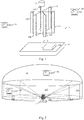
- the Fig. 1 schematically illustrates an example of a drone system.
- a drone system 1 comprises a command station 10 making it possible to simultaneously control drones 3A and 3B.
- the control station 10 comprises an antenna system 11 comprising a plurality of antennas.
- the control station 10 comprises a processing module 100.
- the plurality of antennas comprises six sectoral antennas 11A, 11B, 11C, 11D, 11E and 11F and an omnidirectional antenna 12.
- Each sectoral antenna makes it possible to cover at "- 3dB” a azimuth of "60 °" and an elevation of "+ 8 °".
- the sectoral antennas each have a gain of “+ 14dBi”.
- the omnidirectional antenna 12 covers an azimuth of "360 °” at “-3dB” and from “+ 8 °” to “+ 90 °” in elevation with a gain ranging from “+2.5 dBi” to "+6 dBi "
- the omnidirectional antenna 12 is used at a short distance for drone passages over the antenna system 11 of the control station 10.
- Each drone (3A or 3B) includes an antenna system (not shown) comprising two omnidirectional antennas (not shown), an omnidirectional antenna enabling an azimuth of “360 °” and “0 °” to "to be covered at" -3dB " + 90 ° ”in elevation and an omnidirectional antenna allowing to cover at“ -3dB ”an azimuth of“ 360 ° ”and from“ 0 ° ”to“ -90 ° ”in elevation.
- the drone system 1 described in relation to the Fig. 1 forms a communication network in which the control station 10 communicates with the drones 3A and 3B.
- the control station 10 and the drones 3A and 3B use uplink communications to exchange in particular control and command data in the direction of the control station 10 to the drone (3A or 3B) and downlink communications to exchange useful data (for example example of observation data) in the drone direction (3A or 3B) to control station 10.
- the control station 10 and the drones 3A and 3B use a medium access technique of the TDMA type.
- the TDMA divides time into several hierarchical levels of temporal divisions which we will not describe below in relation to the Fig. 5 .
- This medium access technique requires time synchronization at each node of the communication network ( ie at the level of the control station 10 and of the drones 3A and 3B) to avoid any time overlap.
- the communication network of the Fig. 1 uses a centralized topology in which the control station 10 acts as a master node , that is to say that the control station 10 temporally clock the entire network.
- the other nodes ie drones 3A and 3B
- the Fig. 2 schematically illustrates an example of a range area around the antenna system 11 of the control station 10.
- the range of area around the antenna system 11 can be seen schematically as a dome placed on a horizontal cylinder having the antenna system at its center. This range includes 7 sectors.
- the six sectoral antennas 11A, 11B, 11C, 11D, 11E and 11F respectively define six sectors 21A, 21B, 21C, 21D, 21E and 21F.
- Each of the 6 sectors 21A, 21B, 21C, 21D, 21E and 21F has a semi-pyramidal form of azimuth "60 °" and "+ 8 °" elevation. All the pyramidal shapes share a single vertex located at the level of the antenna system 11.
- Sectors 21A, 21B, 21C, 21D, 21E and 21F form a combined sector of "360 °" azimuth and "+ 8 °" elevation inscribed in the horizontal cylinder.
- the remaining part of the assembly formed by the dome and the cylinder is the sector 20 covered by the omnidirectional antenna 12.
- the drone 3A is located in the sector 21D covered by the antenna 11D and the drone 3B is located in the sector 20 covered by the antenna 12.
- Fig. 2 represents a theoretical vision of a sector division of a range area and that in reality the range area of an antenna is a transmission lobe having a non-zero intersection with transmission lobes of other antennas from his neighborhood.
- the Fig. 3 schematically illustrates a range area around an antenna system of a drone.
- the range area around the aerial system of a drone can be represented by a sphere.
- the omnidirectional antennas of the antenna system of each drone cut said sphere into two semi-hemispherical sectors ( ie two hemispheres) 30A and 30B separated by a horizontal plane.
- the antenna system 11 of the control station 10 is located in the sector 30B.
- a single antenna of the antenna system 11 and a single antenna of a drone transmit or receive at the same time.
- a procedure for selecting the antenna of the antenna system 11 is implemented periodically by the processing module 100 to determine which antenna offers the best quality of communication between the control station 10 and the drone 3A (respectively the drone 3B) at a given moment.
- a procedure for selecting a drone antenna is implemented periodically by a processing module 300 included in each drone (3A or 3B) to determine which antenna offers the best quality of communication between the control station 10 and said drone at a given time.
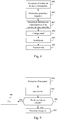
- the Fig. 4A schematically illustrates an example of hardware architecture of the processing module 100 included in the control station 10.
- the processing module 100 then comprises, connected by a communication bus 1000: a processor or CPU (“Central Processing Unit” in English) 1001; a RAM RAM (“Random Access Memory” in English) 1002; a read only memory ROM (“Read Only Memory” in English) 1003; a storage unit such as a hard disk or a storage medium reader, such as an SD card reader (“Secure Digital” in English) 1004; at least one communication interface 1005 allowing the processing module 100 to communicate with other modules or devices.
- the communication interface 1005 allows the processing module 100 to communicate with other modules of the control station 10 such as an antenna switching module making it possible to select an antenna to be used at a given time or with other devices such as 3A and 3B drones.
- Processor 1001 is capable of executing instructions loaded into RAM 1002 from ROM 1003, external memory (not shown), storage medium (such as an SD card), or a communication network. When the control module 10 is powered up, the processor 1001 is capable of reading instructions from RAM 1002 and executing them. In one embodiment, these instructions form a computer program causing the implementation of communications between the control station 10 and each drone of the drone system 1 and of at least part of a method making it possible to discriminate between up and down communications.
- the Fig. 4B schematically illustrates an example of hardware architecture of a processing module 300 included in a drone such as drone 3A or drone 3B.
- the processing module 300 then comprises, connected by a communication bus 3000: a processor or CPU (“Central Processing Unit” in English) 3001; a random access memory RAM (“Random Access Memory” in English) 3002; a read only memory (ROM) 3003; a storage unit such as a hard disk or a storage medium reader, such as an SD (“Secure Digital”) card reader 3004; at least one communication interface 3005 allowing the processing module 300 to communicate with other modules or devices.
- the communication interface 3005 allows the processing module 300 to communicate with other modules such as an antenna switching module making it possible to select an antenna to be used at a given time or to communicate with the control station 10.
- the processor 3001 is capable of executing instructions loaded into the RAM 3002 from the ROM 3003, from an external memory (not shown), a storage medium (such as an SD card), or a communication network.
- processor 3001 is able to read instructions from RAM 3002 and execute them.
- these instructions form a computer program causing the implementation of communications between the drone comprising the processing module 300 and the control station 10 and at least part of a method making it possible to discriminate up and down communications.
- the methods implemented by the processing module 100 and the processing module 300 can be implemented in software form by execution of a set of instructions by a programmable machine, for example a DSP (“Digital Signal Processor” in English) or a microcontroller, or be implemented in hardware form by a machine or a dedicated component, for example an FPGA ("Field-Programmable Gate Array” in English) or an ASIC ("Application-Specific Integrated Circuit" in English).
- a programmable machine for example a DSP (“Digital Signal Processor” in English) or a microcontroller
- FPGA Field-Programmable Gate Array
- ASIC Application-Specific Integrated Circuit
- the Fig. 6 schematically illustrates a transmission module according to the invention.
- the communication interface 1005 of the control station 10 and the communication interface 3005 of each drone 3A and 3B each comprise a transmission module identical to the transmission module described in relation to the Fig. 6 .
- the chosen modulation (ie the GMSK modulation) makes it possible to carry out a convolutional type channel coding due to a memory effect introduced by the Gaussian filter.
- the GMSK modulation is particularly suitable for achieving the desired bit rates on each channel provided in the frequency band used (ie the military frequency band [4.4 GHz; 4.9 GHz] or the civil band [5.031 GHz; 5.091 GHz]).
- the channel coding module 603 comprises two sub-modules: an LDPC coding module 6031 and a BCH coding module 6032.
- the LDPC 6031 coding module can be followed by a row / column type time interleaving module.
- the interleaving is done on the useful data included in each time sub-interval of a time interval (timeslot).
- the transmission module comprises a transmission security module (“TRANsmission SECurity (TRANSEC)” in English terminology) using for example a frequency hopping technique (spread spectrum by frequency evasion, "Frequency Hopping Spread Spectrum (FHSS)” in English terminology).
- TRANSEC transmission security module
- FHSS Frequency Hopping Spread Spectrum
- the Fig. 7 schematically illustrates a reception module.
- the communication interface 1005 of the control station 10 and the communication interface 3005 of each drone 3A and 3B each comprise a reception module identical to the reception module described in relation to the Fig. 7 .
- the LDPC 6031 coding module is followed by a row / column type time interleaving module
- the LDPC 7102 decoding module is preceded by a time deinterlacing module by row / column type.
- the transmission module comprises a transmission security module (TRANSEC)
- the reception module comprises a reciprocal transmission security module.
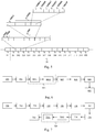
- the Fig. 5 schematically illustrates a technique of access to the medium according to the invention, of the multiple access type with distribution in time dividing time into several hierarchical levels of temporal divisions.
- the TDMA divides time into a first level of hierarchy called epoch ("Epoch" in English terminology) (not shown in the Fig. 5 ) for example with a duration of "1s".
- an epoch is divided into “5” frames, for example with a duration of “200 ms”.
- a frame duration of “200 ms” makes it possible to have a latency time in a communication between a drone and the control station 10 compatible with a transmission of audio conversation data.
- a group of frames 50 is shown in Fig. 5 .
- the group of frames 50 comprises a number of frames equal to the number of antennas of the antenna system 11 of the control station ( ie seven) multiplied by the number of drones active in the drone system 1 ( ie two drones). There are therefore as many frames in a group of frames as possible couples formed by an antenna of the antenna system 11 and a drone.
- the group of frames 50 therefore comprises fourteen frames 501 to 514.
- a frame 414 belongs to a group of fourteen frames preceding the group of frames 50 and a frame 601 belongs to a group of fourteen frames following the group of frames 50.
- We will see by following that the organization into groups of frames makes it possible to define in the drone system 1 which antenna of the antenna system 11 must emit a signal towards a given drone and thus to implement an antenna selection procedure offering the best quality of transmission between the control station 10 and said drone.
- the Fig. 5 gives a detail of the frame 502 included in the group of frames 50, all the frames used in the drone system 1 having an identical frame structure.
- the frame 502 is divided into a plurality of time intervals (“timeslot” in English terminology).
- the plurality of time intervals includes a first interval 500A allowing the control station 10 to emit a first signal called a beacon (“beacon” in English terminology) allowing each drone to synchronize with a time reference given by the control station 10. It is thanks to this beacon that the drones of the drone system 1 can synchronize with the control station 10.
- the position of the frame in the group of frames indicates which drone the beacon is intended for. We therefore consider that the first signal designates a drone among the drones of the drone system 1.
- the plurality of time intervals further comprises a second interval 500B allowing the drone designated by the first signal to emit a second signal thereby enabling it to acknowledge its presence in the drone system 1.
- the intervals 500A and 500B are followed by a succession of intervals 500C.
- the succession of intervals 500C comprises a number of intervals depending on the maximum number of drones that can be controlled in the drone system 1 (ie four drones).
- each drone that can potentially be controlled is associated with "2" consecutive intervals in the succession of intervals: an interval during which the drone can receive data from the control station 10 and an interval during which the drone can transmit data towards the control station 10.
- Each drone and the control station 10 share information describing an allocation of the intervals 500A, 500B and the succession of intervals 500C in a frame .
- the succession of intervals includes eight intervals.
- the communication system of the drone system 1 can therefore manage up to four drones simultaneously.
- the information describing the allocation takes the form of an allocation table shared by all the nodes of the network.
- This allocation table can be fixed or be updated synchronously in all the nodes of the network to, for example, take into account drone stops or arrivals of new drones in the drone system 1.
- At least one allocation table is transmitted during each frame in the interval 500A.
- each node receiving an allocation table during a frame knows the allocation of the intervals in said frame.
- each drone knows in which interval of the frame it must transmit towards the control station 10 and in which interval of the frame it can receive data from the control station 10. From even, the control station 10 knows in which interval it can transmit data towards a given drone and in which interval of a frame it can receive data from a given drone. For example, in the Fig.
- the succession of intervals 500C includes a first interval used to communicate control station 10 to the drone 3A, a second interval used to communicate from the drone 3A to the control station 10, a third interval used to communicate from the control station 10 to the drone 3B and a fourth interval used to communicate from the drone 3B to the control station 10.
- the last four intervals are left free, for example for two other possible drones.
- Each interval has for example a duration of "20 ms” corresponding to a division of a frame into "10" intervals (timeslot).
- An interval of “20 ms” makes it possible to contain a complete LDPC block, which makes it possible to limit the transmission latencies of each of the nodes.
- the Fig. 5 further gives a detail of an interval (timeslot) of the frame 502, each interval of a frame having an identical structure.
- An interval of a frame includes a 5000A subinterval making it possible to take into account propagation times in the drone system 1, and a set of 5000B subintervals (called “burst interval” in English terminology) during which data blocks (“burst” in English terminology) are transmitted.
- the propagation time to reach one of the drones 3A or 3B from the control station 10 at a typical maximum distance of “200 km” for radio signals used in the military frequency band [4.4 GHz; 4.9 GHz] or the civil band [5.031 GHz; 5.091 GHz] is around "0.8 ms".
- each interval includes a set of "5" 5000B subintervals. Therefore each subinterval has a duration of "3.84 ms".
- a sub-interval duration of "3.84 ms" makes it possible to obtain a channel considered to be stationary for the duration of a sub-interval.
- the Fig. 5 also gives a detail of a sub-interval of an interval (timeslot) of a frame, each sub-interval having an identical structure.
- Each sub-interval includes a period 50000A known as the guard interval time (“burst guard time” in English terminology), a period 50000B known as the rise time of high power amplifiers (“High Power Amplifier (HPA) ramping”) in Anglo-Saxon terminology) and a period 50000F known as the descent time of high power amplifiers (“High Power Amplifier (HPA) ramping off” in Anglo-Saxon terminology) intended to take into account the reaction times of electronic components of a drone 3A or 3B or from the control station 10.
- guard interval time (“burst guard time” in English terminology)
- a period 50000B known as the rise time of high power amplifiers (“High Power Amplifier (HPA) ramping”) in Anglo-Saxon terminology
- HPA High Power Amplifier
- HPA High Power Amplifier
- a period 50000C (called preamble sequence ) is used to transmit a preamble allowing the receiving node to make an estimation of the channel in order to carry out frequency, phase, rhythm synchronizations and equalizations of reception signals. These synchronizations make it possible to synchronize sample readings according to the period 50000C in the sub-interval. In addition, as we will not see below, this preamble is used to identify uplink communications from downlink communications.
- a period 50000D (called selection mode ) makes it possible to transmit information representative of a sub-interval number to ensure time synchronization of each of the drones on the control station. Furthermore, this sub-interval number allows each of the nodes to determine whether it is concerned by said sub-interval to send or receive data.
- the data representative of the sub-interval number transmitted during the period 50000D are coded by the coding module BCH 6032 independently of all other data of the sub-interval.
- a period 50000E (called data block ) is used to transmit useful data.
- the useful data transmitted during the 50000E period is coded by the LDPC 6031 coding module.
- the independent encoding of the data corresponding to the sub-interval number makes it possible to decode this data without having to decode the useful data.
- a processing module (100 or 300) is able to determine whether useful data transmitted in a data block is intended for it or not, without having to decode said useful data.
- the data transmitted in the period 50000C, 50000D and 50000E form a data packet.
- each group of frames used in the drone system 1 is organized according to a group structure associating each frame with a pair formed by an antenna of the control station 10 and a drone, each possible couple being associated with a different frame depending on the position of said frame in the group.
- the frames 501 to 507 are associated with the drone 3A and the frames 508 to 514 are associated with the drone 3B.
- the frame 501 is associated with the antenna 11A
- the frame 502 is associated with the antenna 11B
- the frame 503 is associated with the antenna 11C
- the frame 504 is associated with the antenna 11D
- the frame 505 is associated with the antenna 11E
- the frame 506 is associated with the antenna 11F
- the frame 507 is associated with the antenna 12.
- the frame 508 is associated with the antenna 11A
- the frame 509 is associated with the antenna 11B
- the frame 510 is associated with the antenna 11C
- the frame 511 is associated with the antenna 11D
- the frame 512 is associated with the antenna 11E
- the frame 513 is associated with the antenna 11F
- the frame 514 is associated with the antenna 12.
- Each node knowing the duration of each frame and being synchronized with the control station 10, is capable of determining when a frame begins, even when it does not receive data for certain frames. Furthermore, from the information contained in each allocation table, each node is able to determine the group structure. Indeed, from the number of intervals allocated in a frame, each node is capable of determining the number of active drones in the drone system 1. Each drone knowing the number of antennas of the antenna system 11, it is capable of determine the number of frames in a group of frames. In one embodiment, each node knows a group structure for each number of active drones possible in the drone system 1 (ie from "1" to "4" active drones).
- information representative of a position of a frame in a group of frames is transmitted in the interval 500A of each frame.
- each node is capable of determining which is the antenna of the control station 10 transmitting a beacon and to which drone said beacon is intended.
- This information on the group structure allows, among other things, the processing module 100 of the control station 10 to implement an antenna selection method, allowing it to select from the antennas of the antenna system 11, the antenna offering the best quality of communication with a given drone. Indeed, taking the example of the Fig.
- the processing module 100 receives an acknowledgment signal from the drone 3A containing information representative of a quality of reception of the beacon measured by the drone.
- Information representative of a quality of reception is for example a measurement of RSSI (“Received Signal Strength Indication” in English terminology) measured during reception of a beacon.
- the processing module 100 determines which antenna offers the best quality of communication and selects this antenna for a predetermined number of frames according to the frame 507. For example, the processing module 100 selects an antenna for the 3A drone until the next frame containing a tag designating the 3A drone is sent. In the example of the Fig. 1 with two drones in drone system 1, this amounts to selecting a antenna during "7" frames.
- the processing module 100 does the same for the drone 3B from frames 508 to 514 to select the best antenna to communicate with the drone 3B.
- the uplink and downlink communications are discriminated after demodulation and channel decoding in the data link layer and / or the following layers of the OSI model ("Open System Interconnection" in English terminology). , interconnection in open system). It is therefore necessary to demodulate and decode each signal received in order to determine whether it is an uplink or downlink.
- OSI model Open System Interconnection
- the drone system 1 uses in each uplink communication a preamble, called the uplink preamble, orthogonal to the preamble, said the down preamble, used in each downlink communication.
- the Fig. 8 schematically illustrates a method of transmitting a data packet according to the invention.
- the process described in relation to the Fig. 8 is implemented during each transmission of a data packet by the transmission module included in the communication interface 1005 of the control station 10 or the communication interface 3005 of each drone 3A and 3B. This method is implemented by the processing module 100 or 300 using the modules constituting the transmission module.
- a step 800 the processing module 100 (respectively 300) detects a reception of a data block to be transmitted by the transmission module.
- the processing module 100 uses the data block formation module 602 to generate an upstream preamble (respectively a downstream preamble).
- the data block formation module 602 of the control station 10 (of the drone 3A or of the drone 3B respectively) generates the same preamble for each data packet.
- the data block training module 602 of the control station 10 generates rising preambles orthogonal to the descending preambles generated by the data block training module 602 of drones 3A and 3B.
- the rising preamble and the descending preamble are pseudo-random binary sequences with good autocorrelation properties.
- S bin desc An example of binary sequence S bin desc
- the data block formation module 602 generates information representative of a sub-interval number intended to be transmitted in a period 50000D.
- a channel coding is applied to the information representative of a sub-interval number and to the data block to be transmitted.
- a BCH coding is applied by the BCH coding module 6032 to the information representative of the sub-interval number and an LDPC coding is applied by the LDPC coding module 6031 to the data block.
- a data packet is formed comprising the preamble, the information representative of an encoded sub-interval number and the encoded data block.
- the packet thus formed is then modulated by the GMSK modulation module (ie the Gaussian filtering module 604 and the MSK modulation module 605).
- the data packet is transmitted.
- the Fig. 9 schematically illustrates a method of receiving a data packet according to the invention.
- the process described in relation to the Fig. 9 is implemented upon each reception of a data packet by the reception module included in the communication interface 1005 of the control station 10 (respectively the communication interface 3005 of each drone 3A and 3B).
- This method is implemented by the processing module 100 (respectively the processing module 300) using the modules constituting the reception module.
- the processing module 100 determines whether the said packet has been transmitted in the context of an upward or downward communication as a function of a result of a convolution between said modulated data packet received with a reference preamble modulated according to the GMSK modulation, said reference preamble corresponding to the uplink preamble or to the descending preamble depending on whether the method is implemented by the processing module 100 of the control station or the processing module 300 of a drone 3A or 3B.
- the reception module receives a modulated data packet.
- a step 901 the processing module 100 (respectively 300) applies a convolution to the modulated data packet received using the convolution module 707.
- the convolution step 901 is implemented prior to synchronization by the synchronization module in frequency and in phase 708 and at demodulation by the demodulation module GMSK 709.
- the processing module 100 applies a convolution between the modulated data packet received and a modulated preamble of reference kept in memory.
- the modulated reference preamble is for example stored in the storage unit 1004 of the processing module 100 (respectively in the storage unit 3004 of the processing module 300).
- the modulated reference preamble corresponds to a descending preamble for the control station 10 (respectively corresponds to a rising preamble for the drone 3A or 3B).
- the processing module verifies a result of the convolution.
- the processing module 100 deduces therefrom that the preamble included in said package is orthogonal to the preamble sought and therefore that said package is not intended for it. The data packet is then rejected.
- the processing module deduces that the data packet is intended for it.
- the convolution is implemented in the form of a finite impulse response filter (FIR filter) in English terminology.
- FIR filter finite impulse response filter
- a correlation peak is considered to be observed when during a convolution calculation by the convolution module 707, a correlation value greater than or equal to a predefined correlation threshold is obtained.
- the processing module 100 (respectively the processing module 300) continues the reception process by implementing a synchronization step by the frequency and phase synchronization module 708, then by proceeding to the demodulation of the packet by the demodulation module 709 during a step 903. Otherwise, in a step 904, the processing module 100 (respectively 300) rejects the packet without applying any additional processing. In other words, when the processing module 100 of the control station 10 considers that the data packet has been transmitted within the framework of an uplink communication, it rejects said packet. When the processing module 100 of the control station 10 considers that the data packet has been transmitted in the context of a downlink communication, it continues the procedure for receiving the packet and in particular applies demodulation to said data packet.
- the processing module 300 of the drone 3A When the processing module 300 of the drone 3A (or 3B) considers that the data packet has been transmitted in the context of a downlink communication, it rejects said packet. When the processing module 300 of the drone 3A (or 3B) considers that the data packet has been transmitted within the framework of an uplink communication, it continues the procedure for receiving the packet and in particular applies demodulation to said data packet.
Landscapes
- Engineering & Computer Science (AREA)
- Signal Processing (AREA)
- Computer Networks & Wireless Communication (AREA)
- Aviation & Aerospace Engineering (AREA)
- Physics & Mathematics (AREA)
- Astronomy & Astrophysics (AREA)
- General Physics & Mathematics (AREA)
- Power Engineering (AREA)
- Mobile Radio Communication Systems (AREA)
Applications Claiming Priority (2)
| Application Number | Priority Date | Filing Date | Title |
|---|---|---|---|
| FR1601401A FR3056863B1 (fr) | 2016-09-26 | 2016-09-26 | Procede permettant une discrimination de communications montantes ou descendantes |
| PCT/EP2017/074246 WO2018055169A1 (fr) | 2016-09-26 | 2017-09-25 | Procede permettant une discrimination de communications montantes ou descendantes |
Publications (2)
| Publication Number | Publication Date |
|---|---|
| EP3516794A1 EP3516794A1 (fr) | 2019-07-31 |
| EP3516794B1 true EP3516794B1 (fr) | 2020-05-27 |
Family
ID=58162641
Family Applications (1)
| Application Number | Title | Priority Date | Filing Date |
|---|---|---|---|
| EP17772414.3A Active EP3516794B1 (fr) | 2016-09-26 | 2017-09-25 | Procédé permettant une discrimination de communications montantes ou descendantes |
Country Status (6)
| Country | Link |
|---|---|
| US (1) | US10498436B2 (zh) |
| EP (1) | EP3516794B1 (zh) |
| CN (1) | CN109891777B (zh) |
| FR (1) | FR3056863B1 (zh) |
| IL (1) | IL265529B (zh) |
| WO (1) | WO2018055169A1 (zh) |
Families Citing this family (2)
| Publication number | Priority date | Publication date | Assignee | Title |
|---|---|---|---|---|
| CN115412142B (zh) * | 2021-05-28 | 2024-03-01 | 维沃移动通信有限公司 | 处理方法、装置、设备及可读存储介质 |
| CN115441926A (zh) * | 2022-08-02 | 2022-12-06 | 西安电子科技大学 | 一种一站多机分控系统 |
Family Cites Families (10)
| Publication number | Priority date | Publication date | Assignee | Title |
|---|---|---|---|---|
| SE502168C2 (sv) * | 1993-12-29 | 1995-09-04 | Ericsson Telefon Ab L M | Förfarande och anordning vid ett radiokommunikationssystem |
| EP1045533B1 (en) * | 1999-04-12 | 2003-07-16 | Sony International (Europe) GmbH | Communication device and method for distinguishing between different data burst types in a digital telecommunication system |
| AU2002226927A1 (en) * | 2000-11-15 | 2002-05-27 | Ensemble Communications, Inc. | Improved frame structure for a communication system using adaptive modulation |
| US7068631B2 (en) * | 2001-08-06 | 2006-06-27 | Telefonaktiebolaget Lm Ericsson (Publ) | Training sequence hopping in a radio communication system |
| KR20060022259A (ko) * | 2003-06-05 | 2006-03-09 | 각고호우징 게이오기주크 | 무선 통신 장치, 무선 통신 방법, 통신 채널의 할당 방법및 할당 장치 |
| US20090129333A1 (en) * | 2007-11-16 | 2009-05-21 | Qualcomm Incorporated | Preamble design for a wireless signal |
| CN101465841A (zh) * | 2007-12-21 | 2009-06-24 | 普然通讯技术(上海)有限公司 | Eoc网络数据传输系统 |
| WO2009099308A2 (en) * | 2008-02-05 | 2009-08-13 | Lg Electronics Inc. | Method for transmitting control information in wireless communication system |
| WO2012124924A2 (ko) * | 2011-03-11 | 2012-09-20 | 엘지전자 주식회사 | 반송파 집성 기법이 적용된 무선 통신 시스템에서 단말이 신호를 송수신하는 방법 및 이를 위한 장치 |
| CN103490842B (zh) * | 2013-09-26 | 2016-09-28 | 深圳市大疆创新科技有限公司 | 数据传输系统及方法 |
-
2016
- 2016-09-26 FR FR1601401A patent/FR3056863B1/fr not_active Expired - Fee Related
-
2017
- 2017-09-25 US US16/336,012 patent/US10498436B2/en active Active
- 2017-09-25 WO PCT/EP2017/074246 patent/WO2018055169A1/fr active Application Filing
- 2017-09-25 EP EP17772414.3A patent/EP3516794B1/fr active Active
- 2017-09-25 CN CN201780066326.6A patent/CN109891777B/zh active Active
-
2019
- 2019-03-21 IL IL265529A patent/IL265529B/en active IP Right Grant
Non-Patent Citations (1)
| Title |
|---|
| None * |
Also Published As
| Publication number | Publication date |
|---|---|
| WO2018055169A1 (fr) | 2018-03-29 |
| FR3056863A1 (fr) | 2018-03-30 |
| CN109891777A (zh) | 2019-06-14 |
| FR3056863B1 (fr) | 2018-09-21 |
| US20190342002A1 (en) | 2019-11-07 |
| CN109891777B (zh) | 2022-05-24 |
| US10498436B2 (en) | 2019-12-03 |
| EP3516794A1 (fr) | 2019-07-31 |
| IL265529A (en) | 2019-05-30 |
| IL265529B (en) | 2019-08-29 |
Similar Documents
| Publication | Publication Date | Title |
|---|---|---|
| EP3381222B1 (fr) | Procede de configuration d'une passerelle | |
| EP2260655B1 (fr) | Station relais a double radio | |
| EP3607673A1 (fr) | Procede de communication spatiale pour des services iot et systeme spatial de telecommunications correspondant | |
| FR2943882A1 (fr) | Procede d'emission pour un reseau sans fil et procede de reception correspondant | |
| EP3488535B1 (fr) | Procédé d'émission, par un terminal d'un système de communication à accès par slot, d'un message avec sauts de fréquence intra-message | |
| EP3516794B1 (fr) | Procédé permettant une discrimination de communications montantes ou descendantes | |
| FR2892591A1 (fr) | Gestion des transferts intercellulaires dans les communications de groupe | |
| EP3516793B1 (fr) | Systeme de communication dans un systeme de drones | |
| EP0616445B1 (fr) | Système de radiocommunication numérique bidirectionnel multiporteuse, station mobile et station de base correspondantes | |
| CA2769537C (fr) | Methode d'acces multiple aux ressources radio dans un reseau ad hoc mobile et systeme mettant en oeuvre la methode | |
| EP3516786B1 (fr) | Procédé de sélection d'une antenne | |
| EP1181786B1 (fr) | Procede de radiocommunication entre une station de base et des terminaux mobiles | |
| EP0767550B1 (fr) | Procédé de saut de fréquence interbande dans un système de radiocommunication cellulaire avec des stations mobiles, et station correspondante | |
| WO2009053402A1 (fr) | Dispositif et procede permettant d'intercepter des communications dans un reseau | |
| WO2019129885A1 (fr) | Procédé et système pour l'accrochage d'un terminal dans un réseau satellitaire | |
| EP3675546A1 (fr) | Scanner radio embarqué dans une structure mobile d'un système de radiocommunications, et procédé d'utilisation du scanner radio | |
| FR3091437A1 (fr) | Scanner radio embarqué dans une structure mobile d’un système de radiocommunications | |
| EP1088414A1 (fr) | Procede de reduction d'interference entre utilisateurs et utilisation dans un reseau d'acces radio | |
| FR2934734A1 (fr) | Procede d'acces par un noeud requerant a un canal principal de transmission d'un reseau de communication, noeud requerant, produit programme d'ordinateur et moyen de stockage correspondants. |
Legal Events
| Date | Code | Title | Description |
|---|---|---|---|
| STAA | Information on the status of an ep patent application or granted ep patent |
Free format text: STATUS: UNKNOWN |
|
| STAA | Information on the status of an ep patent application or granted ep patent |
Free format text: STATUS: THE INTERNATIONAL PUBLICATION HAS BEEN MADE |
|
| PUAI | Public reference made under article 153(3) epc to a published international application that has entered the european phase |
Free format text: ORIGINAL CODE: 0009012 |
|
| STAA | Information on the status of an ep patent application or granted ep patent |
Free format text: STATUS: REQUEST FOR EXAMINATION WAS MADE |
|
| 17P | Request for examination filed |
Effective date: 20190423 |
|
| AK | Designated contracting states |
Kind code of ref document: A1 Designated state(s): AL AT BE BG CH CY CZ DE DK EE ES FI FR GB GR HR HU IE IS IT LI LT LU LV MC MK MT NL NO PL PT RO RS SE SI SK SM TR |
|
| AX | Request for extension of the european patent |
Extension state: BA ME |
|
| DAV | Request for validation of the european patent (deleted) | ||
| DAX | Request for extension of the european patent (deleted) | ||
| REG | Reference to a national code |
Ref country code: DE Ref legal event code: R079 Ref document number: 602017017424 Country of ref document: DE Free format text: PREVIOUS MAIN CLASS: H04B0007260000 Ipc: H04B0007185000 |
|
| GRAP | Despatch of communication of intention to grant a patent |
Free format text: ORIGINAL CODE: EPIDOSNIGR1 |
|
| STAA | Information on the status of an ep patent application or granted ep patent |
Free format text: STATUS: GRANT OF PATENT IS INTENDED |
|
| RIC1 | Information provided on ipc code assigned before grant |
Ipc: H04B 7/06 20060101ALI20200207BHEP Ipc: H04B 7/26 20060101ALI20200207BHEP Ipc: H04B 7/185 20060101AFI20200207BHEP Ipc: H04B 7/08 20060101ALI20200207BHEP Ipc: B64C 39/02 20060101ALI20200207BHEP |
|
| INTG | Intention to grant announced |
Effective date: 20200306 |
|
| GRAS | Grant fee paid |
Free format text: ORIGINAL CODE: EPIDOSNIGR3 |
|
| GRAA | (expected) grant |
Free format text: ORIGINAL CODE: 0009210 |
|
| STAA | Information on the status of an ep patent application or granted ep patent |
Free format text: STATUS: THE PATENT HAS BEEN GRANTED |
|
| AK | Designated contracting states |
Kind code of ref document: B1 Designated state(s): AL AT BE BG CH CY CZ DE DK EE ES FI FR GB GR HR HU IE IS IT LI LT LU LV MC MK MT NL NO PL PT RO RS SE SI SK SM TR |
|
| REG | Reference to a national code |
Ref country code: GB Ref legal event code: FG4D Free format text: NOT ENGLISH |
|
| REG | Reference to a national code |
Ref country code: CH Ref legal event code: EP |
|
| REG | Reference to a national code |
Ref country code: AT Ref legal event code: REF Ref document number: 1275649 Country of ref document: AT Kind code of ref document: T Effective date: 20200615 |
|
| REG | Reference to a national code |
Ref country code: DE Ref legal event code: R096 Ref document number: 602017017424 Country of ref document: DE |
|
| REG | Reference to a national code |
Ref country code: LT Ref legal event code: MG4D |
|
| PG25 | Lapsed in a contracting state [announced via postgrant information from national office to epo] |
Ref country code: LT Free format text: LAPSE BECAUSE OF FAILURE TO SUBMIT A TRANSLATION OF THE DESCRIPTION OR TO PAY THE FEE WITHIN THE PRESCRIBED TIME-LIMIT Effective date: 20200527 Ref country code: FI Free format text: LAPSE BECAUSE OF FAILURE TO SUBMIT A TRANSLATION OF THE DESCRIPTION OR TO PAY THE FEE WITHIN THE PRESCRIBED TIME-LIMIT Effective date: 20200527 Ref country code: SE Free format text: LAPSE BECAUSE OF FAILURE TO SUBMIT A TRANSLATION OF THE DESCRIPTION OR TO PAY THE FEE WITHIN THE PRESCRIBED TIME-LIMIT Effective date: 20200527 Ref country code: IS Free format text: LAPSE BECAUSE OF FAILURE TO SUBMIT A TRANSLATION OF THE DESCRIPTION OR TO PAY THE FEE WITHIN THE PRESCRIBED TIME-LIMIT Effective date: 20200927 Ref country code: NO Free format text: LAPSE BECAUSE OF FAILURE TO SUBMIT A TRANSLATION OF THE DESCRIPTION OR TO PAY THE FEE WITHIN THE PRESCRIBED TIME-LIMIT Effective date: 20200827 Ref country code: GR Free format text: LAPSE BECAUSE OF FAILURE TO SUBMIT A TRANSLATION OF THE DESCRIPTION OR TO PAY THE FEE WITHIN THE PRESCRIBED TIME-LIMIT Effective date: 20200828 Ref country code: PT Free format text: LAPSE BECAUSE OF FAILURE TO SUBMIT A TRANSLATION OF THE DESCRIPTION OR TO PAY THE FEE WITHIN THE PRESCRIBED TIME-LIMIT Effective date: 20200928 |
|
| REG | Reference to a national code |
Ref country code: NL Ref legal event code: MP Effective date: 20200527 |
|
| PG25 | Lapsed in a contracting state [announced via postgrant information from national office to epo] |
Ref country code: HR Free format text: LAPSE BECAUSE OF FAILURE TO SUBMIT A TRANSLATION OF THE DESCRIPTION OR TO PAY THE FEE WITHIN THE PRESCRIBED TIME-LIMIT Effective date: 20200527 Ref country code: RS Free format text: LAPSE BECAUSE OF FAILURE TO SUBMIT A TRANSLATION OF THE DESCRIPTION OR TO PAY THE FEE WITHIN THE PRESCRIBED TIME-LIMIT Effective date: 20200527 Ref country code: LV Free format text: LAPSE BECAUSE OF FAILURE TO SUBMIT A TRANSLATION OF THE DESCRIPTION OR TO PAY THE FEE WITHIN THE PRESCRIBED TIME-LIMIT Effective date: 20200527 Ref country code: BG Free format text: LAPSE BECAUSE OF FAILURE TO SUBMIT A TRANSLATION OF THE DESCRIPTION OR TO PAY THE FEE WITHIN THE PRESCRIBED TIME-LIMIT Effective date: 20200827 |
|
| REG | Reference to a national code |
Ref country code: AT Ref legal event code: MK05 Ref document number: 1275649 Country of ref document: AT Kind code of ref document: T Effective date: 20200527 |
|
| PG25 | Lapsed in a contracting state [announced via postgrant information from national office to epo] |
Ref country code: NL Free format text: LAPSE BECAUSE OF FAILURE TO SUBMIT A TRANSLATION OF THE DESCRIPTION OR TO PAY THE FEE WITHIN THE PRESCRIBED TIME-LIMIT Effective date: 20200527 Ref country code: AL Free format text: LAPSE BECAUSE OF FAILURE TO SUBMIT A TRANSLATION OF THE DESCRIPTION OR TO PAY THE FEE WITHIN THE PRESCRIBED TIME-LIMIT Effective date: 20200527 |
|
| PG25 | Lapsed in a contracting state [announced via postgrant information from national office to epo] |
Ref country code: ES Free format text: LAPSE BECAUSE OF FAILURE TO SUBMIT A TRANSLATION OF THE DESCRIPTION OR TO PAY THE FEE WITHIN THE PRESCRIBED TIME-LIMIT Effective date: 20200527 Ref country code: DK Free format text: LAPSE BECAUSE OF FAILURE TO SUBMIT A TRANSLATION OF THE DESCRIPTION OR TO PAY THE FEE WITHIN THE PRESCRIBED TIME-LIMIT Effective date: 20200527 Ref country code: SM Free format text: LAPSE BECAUSE OF FAILURE TO SUBMIT A TRANSLATION OF THE DESCRIPTION OR TO PAY THE FEE WITHIN THE PRESCRIBED TIME-LIMIT Effective date: 20200527 Ref country code: EE Free format text: LAPSE BECAUSE OF FAILURE TO SUBMIT A TRANSLATION OF THE DESCRIPTION OR TO PAY THE FEE WITHIN THE PRESCRIBED TIME-LIMIT Effective date: 20200527 Ref country code: AT Free format text: LAPSE BECAUSE OF FAILURE TO SUBMIT A TRANSLATION OF THE DESCRIPTION OR TO PAY THE FEE WITHIN THE PRESCRIBED TIME-LIMIT Effective date: 20200527 Ref country code: IT Free format text: LAPSE BECAUSE OF FAILURE TO SUBMIT A TRANSLATION OF THE DESCRIPTION OR TO PAY THE FEE WITHIN THE PRESCRIBED TIME-LIMIT Effective date: 20200527 Ref country code: CZ Free format text: LAPSE BECAUSE OF FAILURE TO SUBMIT A TRANSLATION OF THE DESCRIPTION OR TO PAY THE FEE WITHIN THE PRESCRIBED TIME-LIMIT Effective date: 20200527 Ref country code: RO Free format text: LAPSE BECAUSE OF FAILURE TO SUBMIT A TRANSLATION OF THE DESCRIPTION OR TO PAY THE FEE WITHIN THE PRESCRIBED TIME-LIMIT Effective date: 20200527 |
|
| PG25 | Lapsed in a contracting state [announced via postgrant information from national office to epo] |
Ref country code: PL Free format text: LAPSE BECAUSE OF FAILURE TO SUBMIT A TRANSLATION OF THE DESCRIPTION OR TO PAY THE FEE WITHIN THE PRESCRIBED TIME-LIMIT Effective date: 20200527 Ref country code: SK Free format text: LAPSE BECAUSE OF FAILURE TO SUBMIT A TRANSLATION OF THE DESCRIPTION OR TO PAY THE FEE WITHIN THE PRESCRIBED TIME-LIMIT Effective date: 20200527 |
|
| REG | Reference to a national code |
Ref country code: DE Ref legal event code: R097 Ref document number: 602017017424 Country of ref document: DE |
|
| PLBE | No opposition filed within time limit |
Free format text: ORIGINAL CODE: 0009261 |
|
| STAA | Information on the status of an ep patent application or granted ep patent |
Free format text: STATUS: NO OPPOSITION FILED WITHIN TIME LIMIT |
|
| REG | Reference to a national code |
Ref country code: CH Ref legal event code: PL |
|
| 26N | No opposition filed |
Effective date: 20210302 |
|
| REG | Reference to a national code |
Ref country code: BE Ref legal event code: MM Effective date: 20200930 |
|
| PG25 | Lapsed in a contracting state [announced via postgrant information from national office to epo] |
Ref country code: LU Free format text: LAPSE BECAUSE OF NON-PAYMENT OF DUE FEES Effective date: 20200925 |
|
| PG25 | Lapsed in a contracting state [announced via postgrant information from national office to epo] |
Ref country code: LI Free format text: LAPSE BECAUSE OF NON-PAYMENT OF DUE FEES Effective date: 20200930 Ref country code: IE Free format text: LAPSE BECAUSE OF NON-PAYMENT OF DUE FEES Effective date: 20200925 Ref country code: CH Free format text: LAPSE BECAUSE OF NON-PAYMENT OF DUE FEES Effective date: 20200930 Ref country code: BE Free format text: LAPSE BECAUSE OF NON-PAYMENT OF DUE FEES Effective date: 20200930 |
|
| PG25 | Lapsed in a contracting state [announced via postgrant information from national office to epo] |
Ref country code: TR Free format text: LAPSE BECAUSE OF FAILURE TO SUBMIT A TRANSLATION OF THE DESCRIPTION OR TO PAY THE FEE WITHIN THE PRESCRIBED TIME-LIMIT Effective date: 20200527 Ref country code: MT Free format text: LAPSE BECAUSE OF FAILURE TO SUBMIT A TRANSLATION OF THE DESCRIPTION OR TO PAY THE FEE WITHIN THE PRESCRIBED TIME-LIMIT Effective date: 20200527 Ref country code: CY Free format text: LAPSE BECAUSE OF FAILURE TO SUBMIT A TRANSLATION OF THE DESCRIPTION OR TO PAY THE FEE WITHIN THE PRESCRIBED TIME-LIMIT Effective date: 20200527 |
|
| PG25 | Lapsed in a contracting state [announced via postgrant information from national office to epo] |
Ref country code: MK Free format text: LAPSE BECAUSE OF FAILURE TO SUBMIT A TRANSLATION OF THE DESCRIPTION OR TO PAY THE FEE WITHIN THE PRESCRIBED TIME-LIMIT Effective date: 20200527 Ref country code: MC Free format text: LAPSE BECAUSE OF FAILURE TO SUBMIT A TRANSLATION OF THE DESCRIPTION OR TO PAY THE FEE WITHIN THE PRESCRIBED TIME-LIMIT Effective date: 20200527 |
|
| PG25 | Lapsed in a contracting state [announced via postgrant information from national office to epo] |
Ref country code: SI Free format text: LAPSE BECAUSE OF FAILURE TO SUBMIT A TRANSLATION OF THE DESCRIPTION OR TO PAY THE FEE WITHIN THE PRESCRIBED TIME-LIMIT Effective date: 20200527 |
|
| PGFP | Annual fee paid to national office [announced via postgrant information from national office to epo] |
Ref country code: DE Payment date: 20240820 Year of fee payment: 8 |
|
| PGFP | Annual fee paid to national office [announced via postgrant information from national office to epo] |
Ref country code: GB Payment date: 20240820 Year of fee payment: 8 |
|
| PGFP | Annual fee paid to national office [announced via postgrant information from national office to epo] |
Ref country code: FR Payment date: 20240820 Year of fee payment: 8 |