EP3516440B2 - Microscope system - Google Patents
Microscope system Download PDFInfo
- Publication number
- EP3516440B2 EP3516440B2 EP17781403.5A EP17781403A EP3516440B2 EP 3516440 B2 EP3516440 B2 EP 3516440B2 EP 17781403 A EP17781403 A EP 17781403A EP 3516440 B2 EP3516440 B2 EP 3516440B2
- Authority
- EP
- European Patent Office
- Prior art keywords
- scanning
- operating state
- functional unit
- sample
- microscope
- Prior art date
- Legal status (The legal status is an assumption and is not a legal conclusion. Google has not performed a legal analysis and makes no representation as to the accuracy of the status listed.)
- Active
Links
- 238000005286 illumination Methods 0.000 claims description 74
- 238000001514 detection method Methods 0.000 claims description 25
- 230000003287 optical effect Effects 0.000 claims description 23
- 238000003384 imaging method Methods 0.000 claims description 21
- 210000001747 pupil Anatomy 0.000 claims description 17
- 238000000034 method Methods 0.000 claims description 6
- 230000005284 excitation Effects 0.000 claims description 5
- 238000000386 microscopy Methods 0.000 description 4
- 230000008569 process Effects 0.000 description 4
- 230000008901 benefit Effects 0.000 description 3
- 230000000295 complement effect Effects 0.000 description 3
- 230000000694 effects Effects 0.000 description 3
- 230000004075 alteration Effects 0.000 description 2
- 230000003750 conditioning effect Effects 0.000 description 2
- 230000008878 coupling Effects 0.000 description 2
- 238000010168 coupling process Methods 0.000 description 2
- 238000005859 coupling reaction Methods 0.000 description 2
- 230000005855 radiation Effects 0.000 description 2
- 230000004913 activation Effects 0.000 description 1
- 230000006978 adaptation Effects 0.000 description 1
- 238000004458 analytical method Methods 0.000 description 1
- 238000013459 approach Methods 0.000 description 1
- 230000002146 bilateral effect Effects 0.000 description 1
- 238000004624 confocal microscopy Methods 0.000 description 1
- 238000010276 construction Methods 0.000 description 1
- 230000001419 dependent effect Effects 0.000 description 1
- 230000001627 detrimental effect Effects 0.000 description 1
- 238000011161 development Methods 0.000 description 1
- 230000018109 developmental process Effects 0.000 description 1
- 238000006073 displacement reaction Methods 0.000 description 1
- 230000003993 interaction Effects 0.000 description 1
- 238000001000 micrograph Methods 0.000 description 1
- 230000004048 modification Effects 0.000 description 1
- 238000012986 modification Methods 0.000 description 1
- 238000012545 processing Methods 0.000 description 1
- 238000004621 scanning probe microscopy Methods 0.000 description 1
- 238000007493 shaping process Methods 0.000 description 1
- 230000001360 synchronised effect Effects 0.000 description 1
Images


Classifications
-
- G—PHYSICS
- G02—OPTICS
- G02B—OPTICAL ELEMENTS, SYSTEMS OR APPARATUS
- G02B21/00—Microscopes
- G02B21/0004—Microscopes specially adapted for specific applications
- G02B21/002—Scanning microscopes
- G02B21/0024—Confocal scanning microscopes (CSOMs) or confocal "macroscopes"; Accessories which are not restricted to use with CSOMs, e.g. sample holders
- G02B21/0036—Scanning details, e.g. scanning stages
- G02B21/0048—Scanning details, e.g. scanning stages scanning mirrors, e.g. rotating or galvanomirrors, MEMS mirrors
-
- G—PHYSICS
- G02—OPTICS
- G02B—OPTICAL ELEMENTS, SYSTEMS OR APPARATUS
- G02B21/00—Microscopes
- G02B21/0004—Microscopes specially adapted for specific applications
- G02B21/002—Scanning microscopes
- G02B21/0024—Confocal scanning microscopes (CSOMs) or confocal "macroscopes"; Accessories which are not restricted to use with CSOMs, e.g. sample holders
- G02B21/0032—Optical details of illumination, e.g. light-sources, pinholes, beam splitters, slits, fibers
-
- G—PHYSICS
- G02—OPTICS
- G02B—OPTICAL ELEMENTS, SYSTEMS OR APPARATUS
- G02B21/00—Microscopes
- G02B21/06—Means for illuminating specimens
- G02B21/08—Condensers
- G02B21/082—Condensers for incident illumination only
-
- G—PHYSICS
- G02—OPTICS
- G02B—OPTICAL ELEMENTS, SYSTEMS OR APPARATUS
- G02B21/00—Microscopes
- G02B21/36—Microscopes arranged for photographic purposes or projection purposes or digital imaging or video purposes including associated control and data processing arrangements
-
- G—PHYSICS
- G02—OPTICS
- G02B—OPTICAL ELEMENTS, SYSTEMS OR APPARATUS
- G02B21/00—Microscopes
- G02B21/36—Microscopes arranged for photographic purposes or projection purposes or digital imaging or video purposes including associated control and data processing arrangements
- G02B21/365—Control or image processing arrangements for digital or video microscopes
- G02B21/367—Control or image processing arrangements for digital or video microscopes providing an output produced by processing a plurality of individual source images, e.g. image tiling, montage, composite images, depth sectioning, image comparison
Definitions
- the invention relates to a microscope system with a light sheet microscopic functional unit that is designed to image a sample in a first operating state of the microscope system using a light sheet-like illumination light distribution, and a scanning microscopic functional unit that is designed to image the sample in a second operating state of the microscope system using a point-like illumination light distribution .
- So-called light disc or light sheet microscopes are known from the prior art, which generate a light sheet-like illumination light distribution in order to illuminate only a thin layer in the sample.
- light sheet microscopes which have two separate lenses for illumination and detection on the sample side
- light sheet microscopes are now also being used that make do with a single lens facing the sample.
- OPM oblique plane microscope
- a variation of a sloping plane microscope is known, which enables a lateral scanning, ie scanning perpendicular to the direction of light propagation, of the sample volume with the aid of two deflection elements.
- Such a microscope is also referred to as a SCAPE microscope (SCAPE: "swept confocally-aligned planar excitation").
- a light sheet microscope images the sample by means of a light sheet-like illumination light distribution
- the sample is imaged point by point in conventional scanning microscopes, eg confocal or multiphoton microscopes.
- Such a scanning microscope accordingly generates a point-like illumination light distribution, which is moved over the sample with the aid of scanning elements in order to scan the same along two orthogonal scanning axes with the illumination light distribution.
- Both inclined plane microscopes and scanning microscopes each of which is equipped with one or more scanning elements in order to scan the sample with the respective illumination light distribution, require a telescope system that maps the exit pupil of the objective lens on the sample in the form of a real image onto the respective scanning element.
- Such a telescope system must be extremely low in aberrations for both orthoscopic and conoscopic images in order to ensure adequate imaging quality. This makes it comparatively expensive.
- the object of the invention is to specify a microscope system and a method for imaging a sample using a light microscope, which allows both light sheet microscopy and raster microscopy to be used with comparatively little technical effort.
- the microscope system comprises a light sheet microscopic functional unit, which is designed to image a sample in a first operating state of the microscope system by means of a light sheet-like illumination light distribution, a scanning microscopic functional unit, which is designed to form the sample in a second operating state of the microscope system by means of a point-like illumination light distribution, a first Scanning element that is designed to scan the sample in the first operating state with the light sheet-like illumination light distribution generated by the light-sheet-microscopic functional unit and to scan the sample in the second operating state with the point-like illumination light distribution generated by the scanning-microscopic functional unit, a second scanning element that is designed to scan the sample in the second operating state with the punctiform illumination light distribution generated by the scanning microscopic functional unit in one axis and thereby in the second operating state, together with the first scanning element, to effect a two-axis scanning of the sample with the punctiform illumination light distribution generated by the scanning microscopic functional unit, and a control unit configured to switch between the first operating state and
- the invention makes use of the fact that both an inclined plane microscope, e.g. an OPM or a SCAPE microscope, and a scanning microscope of the type mentioned at the outset have a uniaxial scanning element, i.e. an element that causes light to be scanned along a single scanning axis.
- this element referred to as a scanning element, is used to move the light sheet-like illumination light distribution for volume imaging transversely to the direction of propagation of the illumination light.
- the scanning microscope it effects one of the two usually orthogonal scanning movements of the punctiform light distribution.
- This element can thus be used both in the light sheet microscopic functional unit and in the raster microscopic functional unit for scanning illumination of the sample.
- the first scanning element alone is sufficient to scan the sample with the illuminating light.
- the invention provides, in the second operating state of the microscope system, which is used for raster microscopic imaging by means of a point-like illumination light distribution, to use a second scanning element in addition to the first scanning element, which also causes uniaxial scanning.
- the two scanning axes are preferably orthogonal to one another in the second operating state. The two uniaxially acting scanning elements thus form a two-axis scanning system in their interaction.
- the microscope system Via the first scanning element used in the two operating states according to the invention, the microscope system combines the two application-related complementary imaging methods of a light sheet microscope and a point-by-point scanning microscope. Switching between these two imaging methods is coordinated by a control unit.
- This can, for example, be designed in such a way that it is solely responsible for controlling the scanning elements and otherwise leaves the control to separate control devices, which in particular control the two different imaging processes.
- the control unit can also control the overall operation of the microscope system, i.e. also all imaging processes.
- the first scanning element and the second scanning element preferably form a telecentric scanning system in the second operating state of the microscope system.
- the light sheet microscopic functional unit and the scanning microscopic functional unit have a common lens facing the sample, each for illumination and detection. This enables a particularly compact construction of the microscope system according to the invention.
- the light sheet microscopic functional unit and the scanning microscopic functional unit have a common telescope optics, which images an exit pupil of the objective onto the first scanning element. Since telescope optics that can be used to generate a pupil image, as mentioned at the outset, have particularly low levels of aberrations and are therefore comparatively expensive, the joint use of the telescope optics offers a considerable cost advantage.
- the microscope system preferably has a microscope stand that carries the common objective and has a connection element to which the common telescope optics can be connected.
- the microscope system in the manner of a microscope module, can be combined particularly easily with an existing microscope stand, e.g. an upright microscope, an inverted microscope or a fixed-stage microscope.
- an existing microscope stand e.g. an upright microscope, an inverted microscope or a fixed-stage microscope.
- the light sheet microscopic functional unit and the raster microscopic functional unit have the common telescope optics, so that only a single connection element has to be provided for coupling to the microscope stand.
- the first scanning element and the second scanning element are each designed, for example, as a galvanometer mirror or microelectromechanical mirror (MEMS).
- the first scanning element can be tilted about a first tilting axis and the second scanning element can be tilted about a second tilting axis, which is preferably perpendicular to the first tilting axis.
- the first scanning element can be tilted within a first tilting angle range in the first operating state and within a second tilting angle range, which is different from the first tilting angle range, in the second operating state.
- the microscope system preferably contains a switching element that can be controlled by a control unit for switching between the first operating state and the second operating state.
- the switchover element is formed, for example, by the first deflection element, which can be tilted for switching the operating state between a tilted position within the first tilting angle range and a tilted position within the second tilting angle range.
- This embodiment makes use of the fact that, viewed from the perspective of the telescope optics imaging the objective pupil onto the first scanning element, there are two tilt angle ranges accessible to the first scanning element, which can be assigned to the two operating states.
- This makes it possible for the first scanning element, on the one hand, to carry out the scanning required for the application along the first scanning axis, and, on the other hand, to select the appropriate tilting angle range in order to achieve the desired operating state to realize.
- the switching element is formed by a light deflection element that is provided separately from the first scanning element.
- This light deflection element is, for example, a mirror or prism that can be moved into the beam path and removed from it. It can also be designed in the form of a deflection element which remains in the beam path and which is adjusted, for example tilted, to select the operating state.
- This embodiment has the further advantage that the telescope optics, which images the objective pupil onto the first scanning element, only have to be provided once and occupy only one adaptation point on the microscope if the invention is designed as a module for a conventional microscope.
- the light sheet microscopic functional unit comprises an illumination optics, which is designed to generate the light sheet-like illumination light distribution in an intermediate image space, a telecentric transport optics on both sides, which is designed to transmit the light sheet-like illumination light distribution generated in the intermediate image space into the sample, and one with the light sheet-like illumination light distribution to image the illuminated area of the sample as an intermediate image in the intermediate image space, and detection optics, which are designed to image the intermediate image generated in the intermediate image space onto a detector, wherein the optical axes of the illumination optics, the transport optics and the detection optics intersect in the intermediate image space, and wherein the first scanning element is arranged in the transport optics and is designed, in the first operating state, to move the light sheet-like illumination light distribution in the sample transversely, preferably perpendicularly, to the optical axis of the transport optics.
- the aforementioned transport optics which includes the telescope system shared by the light sheet microscopic functional unit and the scanning microscopic functional unit, represents an intermediate imaging system that has the properties required for volume imaging, namely a magnification that corresponds to the refractive index ratio between the sample space and the intermediate space, in order to ensure correct imaging to ensure the aperture angle, and a bilateral, i.e. both object-side and image-side, telecentricity, i.e. a lateral magnification which is independent of the position along the optical axis.
- the scanning microscopic functional unit forms a confocal microscope or a multiphoton microscope.
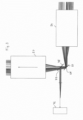
- FIG 1 shows a schematic representation of the structure of a microscope system 10, which represents an embodiment of the invention.
- the microscope system 10 comprises an in figure 1 a light sheet microscopic engine, generally designated 12, and a scanning microscopic engine, generally designated 14.
- the microscope system 10 provides two operating states that can be set as desired, namely a first operating state in which the light sheet microscopic functional unit 12 is used in the manner of a slanted plane microscope to image a sample 16 using a light sheet-like illumination light distribution, and a second operating state in which the scanning microscopic functional unit 14 Sample 16 using a point-like illumination light distribution.
- the light sheet microscopic functional unit 12 is first described below.
- the light sheet microscopic functional unit 12 comprises an illumination optics 18, a transport optics 20 and a detection optics 22, the optical axes O 1 , O 2 , or O 3 in an in figure 1 designated with 24 converge, ie intersect there.
- the purpose of the illumination optics 18 is to focus the illumination light 30 fed to it from a light source 28 into the intermediate image space 24 in such a way that an illumination light distribution is generated there in the manner of a light sheet.
- This light sheet generated in the intermediate image space 24 is then imaged by the transport optics 22 in the sample 16, so that a region of the sample 16 is illuminated with the light sheet and excited to emit fluorescence radiation.
- the fluorescence radiation emitted by the sample 16 again reaches the transport optics 20, which thus images the sample area illuminated with the light sheet as an intermediate image in the intermediate image space 24.
- the intermediate image generated in the intermediate image space 24 of the illuminated Sample area is finally imaged by the detection optics 22 on a detection surface 32 of a detector 34.
- the illumination optics 18 successively contain a beam conditioning unit 36, an adjustment element 38, an ocular lens system 40, a further adjustment element 42, a tube lens element 44 and an illumination objective 46, which faces the intermediate image space 24.
- the beam processing unit 36 contains a cylindrical lens 48 which, in cooperation with the illumination objective 46, is part of an anamorphic optical system which has the function of generating the light sheet in the desired form from the illumination light 30 emitted by the light source 28 in the intermediate image space 24.
- the cylindrical lens 48 focuses the illumination light 30 into the image of the pupil of the illumination objective 46 generated by the ocular lens system 40 and the tube lens system 44.
- the tube lens system 44 and the eyepiece lens system 40 thus form a Galilean telescope with a real intermediate image.
- the two adjustment elements 38 and 42 contained in the illumination optics 18 form an adjustment device that makes it possible to adjust the light sheet relative to the detection surface 32 of the detector 34, more precisely, relative to the image of the detection surface 32 generated by the detection optics 22 in the intermediate image space 24 , on which the light sheet is superimposed.
- the adjusting element 42 is arranged in a plane which is conjugate to an image plane of the illumination objective 46 . Accordingly, the angle at which the illuminating light 30 exits the illuminating lens 46 is changed by tilting the adjusting element 42 .
- the adjustment element 38 is arranged in a plane which is conjugate to the pupil plane of the illumination objective 46 . The position of the illumination light 30 emerging from the illumination lens 46 can thus be adjusted by the adjustment element 38 .
- the two adjustment elements 38 and 42 thus allow the position and angle of the light sheet to be adjusted independently of one another.
- the illumination optics 18 can generate additional, in figure 1 contain elements not explicitly shown, for example a field stop and/or an aperture stop.
- the field stop has the function of limiting the light sheet in the direction in which it is expanded.
- the aperture stop is used to limit the opening angle with which the light sheet is focused.
- the transport optics 20 contain an objective 50, a tube lens system 52, an ocular lens system 54, a further ocular lens system 56, a further tube lens system 58, a deflection element 60, an afocal system 62 and an intermediate imaging lens 64. Both the tube lens system 52 and the The ocular lens system 48 as well as the tube lens system 58 and the ocular lens system 56 each form a Galileo telescope optic.
- the transport optics 20 are designed as a double-sided telecentric optical system.
- the afocal system 62 contained in the transport optics 20 is used to adapt the magnification to the refractive index ratio between the sample space and the intermediate image space 24, which is required for the desired volume image transport. Telescope optics 56 are coupled via a connecting element 53 to a microscope stand 55 on which objective 50 is held.
- the light sheet microscopic functional unit 12 in the transport optics 20 contains a first scanning element 66, which is designed, for example, as a galvanometer mirror or MEMS mirror.
- the sensing element 50 is pivotable about a tilting axis 68 which, with reference to FIG figure 2 specified coordinate system coincides with the z-axis, tiltable.
- the scanning element 66 serves to scan the sample 16 laterally, ie transversely to the optical axis of the objective 50 with the light sheet.
- the scanning element 66 is tilted about the tilting axis 68 within a predetermined first tilting angle range.
- the scanning element 66 is arranged at a point at which the telescope optics 56 generates a real image of an exit pupil 70 of the objective 50 . In other words, the telescope optics 56 thus images the exit pupil 70 onto the first scanning element 66 .
- the detection optics 22 contain a detection objective 72 facing the intermediate image space 24 and a tube lens system 74.
- the intermediate image of the sample area illuminated with the light sheet, which is generated by the transport optics 20 in the intermediate image space 24, is imaged on the detector surface 32 of the detector 40 via the detection objective 72 and the tube lens system 74 .
- the illumination optics 18, the transport optics 20 and the detection optics 22 of the light sheet microscopic functional unit 12 are aligned with one another such that their optical axes O 1 , O 2 , O 3 converge in the intermediate image space 24 .
- the illumination light 30 generated by the light source 28 is coupled into the transport optics 20 as it were by a geometric combination in the area of the intermediate image, which makes it possible to dispense with dichroic beam splitter elements in the area of the transport optics 20 .
- the imaging performance of the Transport optics 20 detrimental pupil displacement can be reliably avoided.
- the scanning microscopic functional unit 14 of the microscope system 10, which is put into operation in the second operating state, is described below.
- the raster microscopic functional unit 14 uses the objective 50 facing the sample 16 and the telescope optics 56 formed from the tube lens system 52 and the ocular lens system 54.
- the first scanning element 66 is also used by the raster microscopic functional unit 14 in the second operating state. This means that the two functional units 12, 14 of the microscope system 10 have shared components in the form of the lens 50, the telescope optics 56 and the first scanning element 66.
- the scanning microscopic functional unit 14 has an excitation/detection module 72 that is spatially separate from the light sheet microscopic functional unit 12.
- the scanning microscopic functional unit 14 also contains a second scanning element 74, which alone in the enlarged partial view figure 2 you can see.
- the second scanning element 74 is also implemented, for example, as a single-axis galvanometer mirror or MEMS mirror.
- the second scanning element 74 can be tilted about a tilting axis 76 which is orthogonal to the tilting axis 68 of the first scanning element 66 .
- the presentation in the figures 1 and 2 is greatly simplified.
- the second scanning element 76 relative to the plane of the drawing figure 2 is inclined, for example by 45 degrees.
- the beam path between the second scanning element 74 and the excitation/detection module 72 does not run in the plane of the drawing, but out of it or into it.
- components that are not explicitly shown can be present, such as in particular additional telescope optics, through which a further real image of the exit pupil 70 of the lens 50 can be generated. This makes it possible to position the second scanning element 74, which is to be located at the location of this pupil image, in the beam path of the functional unit 14 of a scanning microscope as desired.
- the first single-axis scanning element 66 and the second single-axis scanning element 76 form a telecentric two-axis scanning system that can be used to scan the sample 16 with the point-like illumination light distribution generated in the scanning microscopic functional unit 14 in two axes, i.e. along two preferably orthogonal to scan scanning axes. Both scanning elements 66 and 76 forming this two-axis scanning system are conjugate to the exit pupil 70 of the lens 50.
- the first scanning element 66 has the function, in cooperation with the second scanning element 74, of ensuring a two-axis scanning of the sample 16 with the point-like illumination light distribution.
- the first scanning element 68 is tilted about the tilting axis 68 within a second tilting angle range, which differs from the first tilting angle range used in the first operating state.
- first scanning element 66 offers the possibility of using the first scanning element 66 not only for the actual scanning process, which is carried out in the first or in the second operating state, but also as an element for switching between the first operating state and the second operating state. If the first scanning element 66 is in a tilted position that lies within the first tilting angle range, then the first scanning element 66 in the arrangement shown is automatically switched to the light sheet microscopic functional unit 12, as a result of which the first operating state is realized. If the scanning element is then tilted into the second tilt angle range, it is connected to the scanning microscopic functional unit 14, as a result of which the second operating state is selected.
- the microscope system 10 also has a control unit 87, which controls the switching of the operating states by a corresponding activation of the first scanning element 66.
- the control unit 87 can be designed in such a way that it also controls some other or even all operating processes of the microscope system 10 .
- FIG 3 shows a modified embodiment, in which a separate switching element is used for switching between the two operating states 78 is provided.
- the switching element 78 is, for example, a mirror which has a mirror surface 79 facing the second scanning element 66 and is introduced into the beam path between the two ocular lens systems 54, 56 in order to activate the scanning microscopic functional unit 14, i.e. to set the second operating state . If the mirror 78 is removed from the beam path, then the microscope system 10 is in the first operating state.
- a further single-axis scanning element for example in the form of a galvanometer mirror or a MEMS mirror, in the illumination optics 18 of the light sheet microscopic functional unit 12 for light sheet generation instead of the cylinder mirror 48 .
- a scanning element can be arranged, for example, at the point at which, in the exemplary embodiment figure 1 the adjusting element 38 is located.
- the scanning element then effects a scanning movement of the illumination light 30, by which the desired light sheet is built up sequentially.
- the control unit 87 then ensures that the operation of this scanning element is synchronized with the other system components, in particular with the first scanning element 66 .
- the further scanning element additionally present in the illumination optics 18 could be used in the same way for the functional coupling of a functional unit that scans point by point, as is done further above in the exemplary embodiment according to FIGS Figures 1 to 3 for the first sensing element 66 is described. Accordingly, a tilting angle range of this further scanning element that is not used for light sheet generation could be used corresponding to the second tilting angle range of scanning element 66 for the raster microscopic scanning and possibly also for switching between the two operating states.
Description
Die Erfindung betrifft ein Mikroskopsystem mit einer lichtblattmikroskopischen Funktionseinheit, die ausgebildet ist, eine Probe in einem ersten Betriebszustand des Mikroskopsystems mittels einer lichtblattartigen Beleuchtungslichtverteilung abzubilden, und eine rastermikroskopische Funktionseinheit, die ausgebildet ist, die Probe in einem zweiten Betriebszustand des Mikroskopsystems mittels einer punktartigen Beleuchtungslichtverteilung abzubilden.The invention relates to a microscope system with a light sheet microscopic functional unit that is designed to image a sample in a first operating state of the microscope system using a light sheet-like illumination light distribution, and a scanning microscopic functional unit that is designed to image the sample in a second operating state of the microscope system using a point-like illumination light distribution .
Aus dem Stand der Technik sind sogenannte Lichtscheiben- oder Lichtblattmikroskope bekannt, die eine lichtblattartige Beleuchtungslichtverteilung generieren, um in der Probe nur eine dünne Schicht zu beleuchten. Neben Lichtblattmikroskopen, die probenseitig zwei separate Objektive für die Beleuchtung und die Detektion aufweisen, werden mittlerweile auch Lichtblattmikroskope eingesetzt, die mit einem einzigen der Probe zugewandten Objektiv auskommen. Beispielsweise wird in der
Aus der
Während ein Lichtblattmikroskop die Probe also mittels einer lichtblattartigen Beleuchtungslichtverteilung abbildet, erfolgt die Probenabbildung bei herkömmlichen Rastermikroskopen, z.B. Konfokal- oder Multiphotonenmikroskopen, punktweise. Ein solches Rastermikroskop erzeugt demnach eine punktartige Beleuchtungslichtverteilung, die mithilfe von Abtastelementen über die Probe bewegt wird, um diese längs zweier orthogonaler Abtastachsen mit der Beleuchtungslichtverteilung abzutasten. Ein Überblick über die Vielzahl an Rastermikroskopsystemen findet sich z.B. in
Zum Stand der Technik wird ferner auf die
Sowohl Schiefebenenmikroskope als auch Rastermikroskope, die jeweils mit einem oder mehreren Abtastelementen versehen sind, um die Probe mit der jeweiligen Beleuchtungslichtverteilung abzutasten, benötigen ein Fernrohrsystem, das die Austrittspupille des probenseitigen Objektivs in Form eines reellen Bildes auf das jeweilige Abtastelement abbildet. Ein solches Fernrohrsystem muss sowohl für orthoskopische als auch für konoskopische Abbildungen äußerst abberationsarm sein, um eine adäquate Abbildungsgüte zu gewährleisten. Dadurch ist es vergleichsweise teuer.Both inclined plane microscopes and scanning microscopes, each of which is equipped with one or more scanning elements in order to scan the sample with the respective illumination light distribution, require a telescope system that maps the exit pupil of the objective lens on the sample in the form of a real image onto the respective scanning element. Such a telescope system must be extremely low in aberrations for both orthoscopic and conoscopic images in order to ensure adequate imaging quality. This makes it comparatively expensive.
Weiterhin benötigen diese Fernrohrsysteme einen Zugang zur Objektivpupille. Herkömmliche Mikroskope verfügen hierzu über entsprechende Schnittstellen in Form von Anschlüssen, beispielsweise Flansche. Das Vorhalten solcher Schnittstellen ist mechanisch und optisch aufwendig und vergrößert den Platzbedarf des Mikroskops.Furthermore, these telescope systems require access to the objective pupil. For this purpose, conventional microscopes have corresponding interfaces in the form of connections, for example flanges. The provision of such interfaces is mechanically and optically complex and increases the space requirement of the microscope.
Aus der
Da die beiden vorstehend beschriebenen Mikroskopieanwendungen, nämlich die Schiefebenenmikroskopie und die punktweise arbeitende Rastermikroskopie, applikativ komplementäre Bildgebungsansätze darstellen, die sich in der Probenanalyse gewinnbringend ergänzen können ist es wünschenswert, ein Mikroskopsystem bereitzustellen, mit dem sich die beiden Bildgebungsmethoden miteinander kombinieren lassen.Since the two microscopy applications described above, namely inclined plane microscopy and point-by-point scanning microscopy, represent complementary imaging approaches in terms of application, which can complement each other profitably in sample analysis, it is desirable to provide a microscope system with which the two imaging methods can be combined.
Aufgabe der Erfindung ist es, ein Mikroskopsystem und ein Verfahren zur lichtmikroskopischen Abbildung einer Probe anzugeben, das mit vergleichsweise geringem technischem Aufwand sowohl eine lichtblattmikroskopische als auch eine rastermikroskopische Anwendung erlaubt.The object of the invention is to specify a microscope system and a method for imaging a sample using a light microscope, which allows both light sheet microscopy and raster microscopy to be used with comparatively little technical effort.
Die Erfindung löst diese Aufgabe durch die Gegenstände der unabhängigen Ansprüche. Vorteilhafte Weiterbildungen sind in den Unteransprüchen angegeben.The invention solves this problem through the subject matter of the independent claims. Advantageous developments are specified in the dependent claims.
Das erfindungsgemäße Mikroskopsystem umfasst eine lichtblattmikroskopische Funktionseinheit, die ausgebildet ist, eine Probe in einem ersten Betriebszustand des Mikroskopsystems mittels einer lichtblattartigen Beleuchtungslichtverteilung abzubilden, eine rastermikroskopische Funktionseinheit, die ausgebildet ist, die Probe in einem zweiten Betriebszustand des Mikroskopsystems mittels einer punktartigen Beleuchtungslichtverteilung auszubilden, ein erstes Abtastelement, das ausgebildet ist, die Probe in dem ersten Betriebszustand mit der durch die lichtblattmikroskopische Funktionseinheit erzeugten lichtblattartigen Beleuchtungslichtverteilung einachsig abzutasten und die Probe in dem zweiten Betriebszustand mit der durch die rastermikroskopische Funktionseinheit erzeugten punktartigen Beleuchtungslichtverteilung einachsig abzutasten, ein zweites Abtastelement, das ausgebildet ist, die Probe in dem zweiten Betriebszustand mit der durch die rastermikroskopische Funktionseinheit erzeugten punktartigen Beleuchtungslichtverteilung einachsig abzutasten und dadurch in dem zweiten Betriebszustand gemeinsam mit dem ersten Abtastelement eine zweiachsige Abtastung der Probe mit der durch die rastermikroskopische Funktionseinheit erzeugten punktartigen Beleuchtungslichtverteilung zu bewirken, und eine Steuereinheit, die ausgebildet ist, zwischen dem ersten Betriebszustand und dem zweiten Betriebszustand umzuschalten.The microscope system according to the invention comprises a light sheet microscopic functional unit, which is designed to image a sample in a first operating state of the microscope system by means of a light sheet-like illumination light distribution, a scanning microscopic functional unit, which is designed to form the sample in a second operating state of the microscope system by means of a point-like illumination light distribution, a first Scanning element that is designed to scan the sample in the first operating state with the light sheet-like illumination light distribution generated by the light-sheet-microscopic functional unit and to scan the sample in the second operating state with the point-like illumination light distribution generated by the scanning-microscopic functional unit, a second scanning element that is designed to scan the sample in the second operating state with the punctiform illumination light distribution generated by the scanning microscopic functional unit in one axis and thereby in the second operating state, together with the first scanning element, to effect a two-axis scanning of the sample with the punctiform illumination light distribution generated by the scanning microscopic functional unit, and a control unit configured to switch between the first operating state and the second operating state.
Die Erfindung macht sich den Umstand zu Nutze, dass sowohl ein Schiefebenenmikroskop, z.B. ein OPM- oder ein SCAPE-Mikroskop, als auch Rastermikroskop eingangs genannter Art über ein einachsiges Abtastelement verfügen, d.h. über ein Element, das eine Lichtabtastung längs einer einzigen Abtastachse bewirkt. In dem Schiefebenenmikroskop dient dieses als Abtastelement bezeichnete Element dazu, die lichtblattartige Beleuchtungslichtverteilung zur Volumenbildgebung quer zur Ausbreitungsrichtung des Beleuchtungslichtes zu bewegen. Dagegen bewirkt es in dem Rastermikroskop eine der beiden üblicherweise orthogonalen Abtastbewegungen der punktartigen Lichtverteilung. Somit kann dieses vorliegend als erstes Abtastelement bezeichnete Element sowohl in der lichtblattmikroskopischen Funktionseinheit als auch in der rastermikroskopischen Funktionseinheit zur abtastenden Beleuchtung der Probe genutzt werden. In dem ersten Betriebszustand des Mikroskopsystems, in dem die lichtblattmikroskopische Bildgebung erfolgt, reicht allein das erste Abtastelement aus, um die Probe mit dem Beleuchtungslicht abzutasten. Demgegenüber sieht die Erfindung vor, in dem zweiten Betriebszustand des Mikroskopsystems, welcher der rastermikroskopischen Bildgebung mittels einer punktartigen Beleuchtungslichtverteilung dient, zusätzlich zu dem ersten Abtastelement ein zweites Abtastelement zu nutzen, das ebenfalls eine einachsige Abtastung bewirkt. Dabei liegen die beiden Abtastachsen in dem zweiten Betriebszustand vorzugsweise orthogonal zueinander. Die beiden für sich betrachtet einachsig wirkenden Abtastelemente bilden also in ihrem Zusammenwirken ein zweiachsiges Abtastsystem.The invention makes use of the fact that both an inclined plane microscope, e.g. an OPM or a SCAPE microscope, and a scanning microscope of the type mentioned at the outset have a uniaxial scanning element, i.e. an element that causes light to be scanned along a single scanning axis. In the inclined plane microscope, this element, referred to as a scanning element, is used to move the light sheet-like illumination light distribution for volume imaging transversely to the direction of propagation of the illumination light. In contrast, in the scanning microscope it effects one of the two usually orthogonal scanning movements of the punctiform light distribution. This element, referred to here as the first scanning element, can thus be used both in the light sheet microscopic functional unit and in the raster microscopic functional unit for scanning illumination of the sample. In the first operating state of the microscope system, in which the light sheet microscopic imaging takes place, the first scanning element alone is sufficient to scan the sample with the illuminating light. In contrast, the invention provides, in the second operating state of the microscope system, which is used for raster microscopic imaging by means of a point-like illumination light distribution, to use a second scanning element in addition to the first scanning element, which also causes uniaxial scanning. The two scanning axes are preferably orthogonal to one another in the second operating state. The two uniaxially acting scanning elements thus form a two-axis scanning system in their interaction.
Über das in den beiden erfindungsgemäßen Betriebszuständen genutzte erste Abtastelement kombiniert das Mikroskopsystem die beiden applikativ komplementären Bildgebungsverfahren eines Lichtblattmikroskops und eines punktweise rasternden Mikroskops. Die Umschaltung zwischen diesen beiden Bildgebungsverfahren wird von einer Steuereinheit koordiniert. Diese kann beispielsweise so ausgeführt sein, dass sie allein für die Steuerung der Abtastelemente zuständig ist und ansonsten die Kontrolle separaten Steuergeräten überlässt, die insbesondere die beiden unterschiedlichen Bildgebungsprozesse steuern. Alternativ kann die Steuereinheit aber auch den Gesamtbetrieb des Mikroskopsystems steuern, d.h. auch sämtliche Bildgebungsprozesse.Via the first scanning element used in the two operating states according to the invention, the microscope system combines the two application-related complementary imaging methods of a light sheet microscope and a point-by-point scanning microscope. Switching between these two imaging methods is coordinated by a control unit. This can, for example, be designed in such a way that it is solely responsible for controlling the scanning elements and otherwise leaves the control to separate control devices, which in particular control the two different imaging processes. Alternatively, however, the control unit can also control the overall operation of the microscope system, i.e. also all imaging processes.
Vorzugsweise bilden das erste Abtastelement und das zweite Abtastelement in dem zweiten Betriebszustand des Mikroskopsystems ein telezentrisches Abtastsystem.The first scanning element and the second scanning element preferably form a telecentric scanning system in the second operating state of the microscope system.
Die lichtblattmikroskopische Funktionseinheit und die rastermikroskopische Funktionseinheit weisen ein gemeinsames, der Probe zugewandtes Objektiv jeweils zur Beleuchtung und Detektion auf.
Dies ermöglicht einen besonders kompakten Aufbau des erfindungsgemäßen Mikroskopsystems.The light sheet microscopic functional unit and the scanning microscopic functional unit have a common lens facing the sample, each for illumination and detection.
This enables a particularly compact construction of the microscope system according to the invention.
Erfindungsgemäß weisen die lichtblattmikroskopische Funktionseinheit und die rastermikroskopische Funktionseinheit eine gemeinsame Fernohroptik auf, die eine Austrittspupille des Objektivs auf das erste Abtastelement abbildet. Da eine zur Erzeugung eines Pupillenbildes einsetzbare Fernrohroptik, wie eingangs erwähnt, besonders abberationsarm und damit vergleichsweise teuer ist, bietet die gemeinsame Nutzung der Fernrohroptik einen erheblichen Kostenvorteil.According to the invention, the light sheet microscopic functional unit and the scanning microscopic functional unit have a common telescope optics, which images an exit pupil of the objective onto the first scanning element. Since telescope optics that can be used to generate a pupil image, as mentioned at the outset, have particularly low levels of aberrations and are therefore comparatively expensive, the joint use of the telescope optics offers a considerable cost advantage.
Vorzugsweise hat das Mikroskopsystem ein das gemeinsame Objektiv tragendes Mikroskopstativ, das über ein Anschlusselement verfügt, an das die gemeinsame Fernrohroptik anschließbar ist. Auf diese Weise lässt sich das Mikroskopsystem nach Art eines Mikroskopmoduls besonders einfach mit einem schon vorhandenen Mikroskopstativ, z.B. eines aufrechten Mikroskops, eines inversen Mikroskops oder eines Fixed-Stage-Mikroskops kombinieren. Von Vorteil ist hier insbesondere, dass die lichtblattmikroskopische Funktionseinheit und die rastermikroskopische Funktionseinheit über die gemeinsame Fernrohroptik verfügen, so dass nur ein einziges Anschlusselement zur Kopplung an das Mikroskopstativ vorgehalten werden muss.The microscope system preferably has a microscope stand that carries the common objective and has a connection element to which the common telescope optics can be connected. In this way, the microscope system, in the manner of a microscope module, can be combined particularly easily with an existing microscope stand, e.g. an upright microscope, an inverted microscope or a fixed-stage microscope. It is particularly advantageous here that the light sheet microscopic functional unit and the raster microscopic functional unit have the common telescope optics, so that only a single connection element has to be provided for coupling to the microscope stand.
Das erste Abtastelement und das zweite Abtastelement sind beispielsweise jeweils als Galvanometerspiegel oder mikroelektromechanischer Spiegel (MEMS) ausgeführt. Dabei ist das erste Abtastelement um eine erste Kippachse und das zweite Abtastelement um eine zweite Kippachse, die vorzugsweise senkrecht zur ersten Kippachse liegt, verkippbar.The first scanning element and the second scanning element are each designed, for example, as a galvanometer mirror or microelectromechanical mirror (MEMS). The first scanning element can be tilted about a first tilting axis and the second scanning element can be tilted about a second tilting axis, which is preferably perpendicular to the first tilting axis.
In einer besonders bevorzugten Ausführungsform ist das erste Abtastelement in dem ersten Betriebszustand innerhalb eines ersten Kippwinkelbereichs und in dem zweiten Betriebszustand innerhalb eines zweiten Kippwinkelbereichs, der von dem ersten Kippwinkelbereich verschieden ist, verkippbar.In a particularly preferred embodiment, the first scanning element can be tilted within a first tilting angle range in the first operating state and within a second tilting angle range, which is different from the first tilting angle range, in the second operating state.
Vorzugsweise enthält das Mikroskopsystem ein durch eine Steuereinheit ansteuerbares Umschaltelement zum Umschalten zwischen dem ersten Betriebszustand und dem zweiten Betriebszustand.The microscope system preferably contains a switching element that can be controlled by a control unit for switching between the first operating state and the second operating state.
Das Umschaltelement ist beispielsweise durch das erste Ablenkelement gebildet, das zur Betriebszustandsumschaltung zwischen einer innerhalb des ersten Kippwinkelbereichs liegenden Kippstellung und einer innerhalb des zweiten Kippwinkelbereichs liegenden Kippstellung verkippbar ist. Diese Ausführungsform nutzt den Umstand, dass von der die Objektivpupille auf das erste Abtastelement abbildenden Fernrohroptik her gesehen zwei für das erste Abtastelement zugängliche Kippwinkelbereiche existieren, die den beiden Betriebszuständen zugeordnet werden können. Damit ist es möglich, dass das erste Abtastelement einerseits die applikativ erforderliche Abtastung längs der ersten Abtastachse vornimmt und andererseits den passenden Kippwinkelbereich auswählt, um den gewünschten Betriebszustand zu realisieren. Dazu kann es zweckmäßig sein, das erste Abtastelement unter Lichteinfallswinkeln ungleich 45 Grad zu nutzen.The switchover element is formed, for example, by the first deflection element, which can be tilted for switching the operating state between a tilted position within the first tilting angle range and a tilted position within the second tilting angle range. This embodiment makes use of the fact that, viewed from the perspective of the telescope optics imaging the objective pupil onto the first scanning element, there are two tilt angle ranges accessible to the first scanning element, which can be assigned to the two operating states. This makes it possible for the first scanning element, on the one hand, to carry out the scanning required for the application along the first scanning axis, and, on the other hand, to select the appropriate tilting angle range in order to achieve the desired operating state to realize. For this purpose, it can be expedient to use the first scanning element at angles of incidence of light that are not equal to 45 degrees.
In einer alternativen Ausführungsform ist das Umschaltelement durch ein von dem ersten Abtastelement separat vorgesehenes Lichtumlenkelement gebildet. Dieses Lichtumlenkelement ist beispielsweise ein Spiegel oder Prisma, das sich in den Strahlengang fahren und aus diesem entfernen lässt. Es kann auch in Form eines im Strahlengang verbleibenden Umlenkelementes ausgeführt sein, das zur Auswahl des Betriebszustands verstellt, beispielsweise verkippt, wird. Diese Ausführungsform hat den weiteren Vorteil, die Fernrohroptik, welche die Objektivpupille auf das erste Abtastelement abbildet, nur einmal vorhalten zu müssen und nur eine Adaptionsstelle am Mikroskop zu belegen, sofern die Erfindung als Modul für ein herkömmliches Mikroskop ausgeführt ist.In an alternative embodiment, the switching element is formed by a light deflection element that is provided separately from the first scanning element. This light deflection element is, for example, a mirror or prism that can be moved into the beam path and removed from it. It can also be designed in the form of a deflection element which remains in the beam path and which is adjusted, for example tilted, to select the operating state. This embodiment has the further advantage that the telescope optics, which images the objective pupil onto the first scanning element, only have to be provided once and occupy only one adaptation point on the microscope if the invention is designed as a module for a conventional microscope.
In einer vorteilhaften Ausführungsform umfasst die lichtblattmikroskopische Funktionseinheit eine Beleuchtungsoptik, die ausgebildet ist, die lichtblattartige Beleuchtungslichtverteilung in einem Zwischenbildraum zu erzeugen, eine beidseitig telezentrisch ausgebildete Transportoptik, die ausgebildet ist, die in dem Zwischenbildraum erzeugte lichtblattartige Beleuchtungslichtverteilung in die Probe und einen mit der lichtblattartigen Beleuchtungslichtverteilung beleuchteten Bereich der Probe als Zwischenbild in den Zwischenbildraum abzubilden, und eine Detektionsoptik, die ausgebildet ist, das in dem Zwischenbildraum erzeugte Zwischenbild auf einen Detektor abzubilden, wobei die optischen Achsen der Beleuchtungsoptik, der Transportoptik und der Detektionsoptik einander in dem Zwischenbildraum schneiden, und wobei das erste Abtastelement in der Transportoptik angeordnet und ausgebildet ist, in dem ersten Betriebszustand die lichtblattartige Beleuchtungslichtverteilung in der Probe quer, vorzugsweise senkrecht zur optischen Achse der Transportoptik zu bewegen. Die vorgenannte Transportoptik, die das von der lichtblattmikroskopischen Funktionseinheit und der rastermikroskopischen Funktionseinheit gemeinsam genutzte Fernrohrsystem beinhaltet, stellt ein Zwischenabbildungssystem dar, das die für die Volumenbildgebung erforderlichen Eigenschaften aufweist, nämlich eine Vergrößerung, die dem Brechungsindexverhältnis zwischen Probenraum und Zwischenraum entspricht, um eine korrekte Abbildung der Aperturwinkel zu gewährleisten, und eine beidseitige, d.h. sowohl objektseitige als auch bildseitige Telezentrizität, d.h. eine Lateralvergrößerung, die von der Position längs der optischen Achse unabhängig ist.In an advantageous embodiment, the light sheet microscopic functional unit comprises an illumination optics, which is designed to generate the light sheet-like illumination light distribution in an intermediate image space, a telecentric transport optics on both sides, which is designed to transmit the light sheet-like illumination light distribution generated in the intermediate image space into the sample, and one with the light sheet-like illumination light distribution to image the illuminated area of the sample as an intermediate image in the intermediate image space, and detection optics, which are designed to image the intermediate image generated in the intermediate image space onto a detector, wherein the optical axes of the illumination optics, the transport optics and the detection optics intersect in the intermediate image space, and wherein the first scanning element is arranged in the transport optics and is designed, in the first operating state, to move the light sheet-like illumination light distribution in the sample transversely, preferably perpendicularly, to the optical axis of the transport optics. The aforementioned transport optics, which includes the telescope system shared by the light sheet microscopic functional unit and the scanning microscopic functional unit, represents an intermediate imaging system that has the properties required for volume imaging, namely a magnification that corresponds to the refractive index ratio between the sample space and the intermediate space, in order to ensure correct imaging to ensure the aperture angle, and a bilateral, i.e. both object-side and image-side, telecentricity, i.e. a lateral magnification which is independent of the position along the optical axis.
Die Verwendung einer beidseitig telezentrischen Transportoptik und einer damit ermöglichten telezentrischen Abtastanordnung hat gegenüber herkömmlichen Lichtblattmikroskopen, deren Zwischenabbildungsoptiken nicht beidseitig telezentrisch sind, u.a. den Vorteil, dass in der Transportoptik keine Verzerrungen verursacht werden.Compared to conventional light sheet microscopes whose intermediate imaging optics are not telecentric on both sides, the use of transport optics that are telecentric on both sides and a telecentric scanning arrangement made possible by this has the advantage, among other things, that no distortions are caused in the transport optics.
In einer besonders bevorzugten Ausführungsform bildet die rastermikroskopische Funktionseinheit ein Konfokalmikroskop oder ein Multiphotonenmikroskop.In a particularly preferred embodiment, the scanning microscopic functional unit forms a confocal microscope or a multiphoton microscope.
Die Erfindung wird im Folgenden anhand der Figuren näher erläutert. Darin zeigen:
- Fig. 1
- eine schematische Darstellung eines Mikroskopsystems als Ausführungsbeispiel;
- Fig. 2
- eine vergrößerte Teilansicht, welche die beiden Abtastelemente des Mikroskopsystems nach
Figur 1 zeigt; und - Fig. 3
- eine der
Figur 2 entsprechende Teilansicht einer abgewandelten Ausführungsform, die ein separates Lichtumlenkelement zur Umschaltung zwischen den beiden mikroskopischen Funktionseinheiten aufweist.
- 1
- a schematic representation of a microscope system as an embodiment;
- 2
- an enlarged partial view showing the two scanning elements of the microscope system
figure 1 shows; and - 3
- one of the
figure 2 corresponding partial view of a modified embodiment, which has a separate light deflection element for switching between the two microscopic functional units.
Im Weiteren wird zunächst die lichtblattmikroskopische Funktionseinheit 12 beschrieben.The light sheet microscopic
Die lichtblattmikroskopische Funktionseinheit 12 umfasst eine Beleuchtungsoptik 18, eine Transportoptik 20 und eine Detektionsoptik 22, deren optischen Achsen O1, O2, bzw. O3 in einem in
Die Beleuchtungsoptik 18 enthält in Ausbreitungsrichtung des von der Lichtquelle 28 ausgesendeten Beleuchtungslichtes 30 nacheinander eine Strahlaufbereitungseinheit 36, ein Verstellelement 38, ein Okularlinsensystem 40, ein weiteres Verstellelement 42, einen Tubuslinsenelement 44 sowie ein Beleuchtungsobjektiv 46, das dem Zwischenbildraum 24 zugewandt ist.In the propagation direction of the
Die Strahlaufbereitungseinheit 36 enthält eine Zylinderlinse 48, die im Zusammenwirken mit dem Beleuchtungsobjektiv 46 Teil eines anamorphotischen optischen Systems ist, das die Funktion hat, aus dem von der Lichtquelle 28 emittierten Beleuchtungslicht 30 in dem Zwischenbildraum 24 das Lichtblatt in der gewünschten Form zu erzeugen. Dabei fokussiert die Zylinderlinse 48 das Beleuchtungslicht 30 in das von dem Okularlinsensystem 40 und dem Tubuslinsensystem 44 erzeugte Bild der Pupille des Beleuchtungsobjektivs 46. In dem Ausführungsbeispiel nach
Die beiden in der Beleuchtungsoptik 18 enthaltenen Verstellelemente 38 und 42 bilden eine Verstellvorrichtung, die es ermöglicht, das Lichtblatt relativ zur Detektionsfläche 32 des Detektors 34 zu justieren, genauer gesagt, relativ zu dem durch die Detektionsoptik 22 in dem Zwischenbildraum 24 erzeugten Bild der Detektionsfläche 32, dem das Lichtblatt überlagert ist. Dabei ist das Verstellelement 42 in einer Ebene angeordnet, die zu einer Bildebene des Beleuchtungsobjektivs 46 konjugiert ist. Demnach wird durch Verkippen des Verstellelementes 42 der Winkel geändert, unter dem das Beleuchtungslicht 30 aus dem Beleuchtungsobjektiv 46 tritt. Das Verstellelement 38 ist in einer Ebene angeordnet, die zur Pupillenebene des Beleuchtungsobjektivs 46 konjugiert ist. Durch das Verstellelement 38 lässt sich somit die Position des aus dem Beleuchtungsobjektiv 46 austretenden Beleuchtungslichts 30 einstellen. Die beiden Verstellelemente 38 und 42 erlauben es also, Position und Winkel des Lichtblattes unabhängig voneinander zu justieren.The two
Die Beleuchtungsoptik 18 kann für die Lichtblatterzeugung weitere, in
Die Transportoptik 20 enthält von der Probe 16 her gesehen ein Objektiv 50, ein Tubuslinsensystem 52, ein Okularlinsensystem 54, ein weiteres Okularlinsensystem 56, ein weiteres Tubuslinsensystem 58, ein Umlenkelement 60, ein Afokalsystem 62 sowie ein Zwischenabbildungsobjektiv 64. Sowohl das Tubuslinsensystem 52 und das Okularlinsensystem 48 als auch das Tubuslinsensystem 58 und das Okularlinsensystem 56 bilden jeweils eine Galilei-Fernrohroptik. Die Transportoptik 20 ist als beidseitig telezentrisches optisches System ausgeführt. Das in der Transportoptik 20 enthaltene Afokalsystem 62 dient dazu, die für den gewünschten Volumenbildtransport erforderliche Vergrö-ßerungsanpassung an das Brechungsindexverhältnis zwischen Probenraum und Zwischenbildraum 24 vorzunehmen. Die Fernrohroptik 56 ist über ein Anschlusselement 53 an ein Mikroskopstativ 55 gekoppelt, an dem das Objektiv 50 gehalten ist.Seen from the
Wie insbesondere in der vergrößerten Teilansicht nach
Die Detektionsoptik 22 enthält ein dem Zwischenbildraum 24 zugewandtes Detektionsobjektiv 72 sowie ein Tubuslinsensystem 74. Über das Detektionsobjektiv 72 und das Tubuslinsensystem 74 wird das durch die Transportoptik 20 in dem Zwischenbildraum 24 erzeugte Zwischenbild des mit dem Lichtblatt beleuchteten Probenbereichs auf der Detektorfläche 32 des Detektors 40 abgebildet.The
In dem ersten Betriebszustand des Mikroskopsystem 10 sind die Beleuchtungsoptik 18, die Transportoptik 20 und die Detektionsoptik 22 der lichtblattmikroskopischen Funktionseinheit 12 derart aufeinander ausgerichtet, dass ihre optischen Achsen O1, O2, O3 im Zwischenbildraum 24 zusammenlaufen. Dadurch erfolgt die Einkopplung des von der Lichtquelle 28 erzeugten Beleuchtungslichts 30 in die Transportoptik 20 gleichsam durch eine geometrische Kombination im Bereich des Zwischenbildes, was einen Verzicht auf dichroitische Strahlteilerelemente im Bereich der Transportoptik 20 ermöglicht. Somit kann ein die Abbildungsleistung der Transportoptik 20 beeinträchtigender Pupillenversatz zuverlässig vermieden werden.In the first operating state of the
Im Folgenden wird die rastermikroskopische Funktionseinheit 14 des Mikroskopsystems 10 beschrieben, die in dem zweiten Betriebszustand in Betrieb genommen ist.The scanning microscopic
Die rastermikroskopische Funktionseinheit 14 nutzt wie die lichtblattmikroskopische Funktionseinheit 12 das der Probe 16 zugewandte Objektiv 50 sowie die aus dem Tubuslinsensystem 52 und dem Okularlinsensystem 54 gebildete Fernrohroptik 56. Auch das erste Abtastelement 66 wird in dem zweiten Betriebszustand von der rastermikroskopischen Funktionseinheit 14 genutzt. Dies bedeutet, dass die beiden Funktionseinheiten 12, 14 des Mikroskopsystems 10 gemeinsam genutzte Komponenten in Form des Objektivs 50, der Fernrohroptik 56 und des ersten Abtastelementes 66 aufweisen.Like the light sheet microscopic
Des Weiteren verfügt die rastermikroskopische Funktionseinheit 14 über ein von der lichtblattmikroskopischen Funktionseinheit 12 räumlich getrenntes Anregungs-/Detektionsmodul 72. Dieses enthält die an sich bekannten und deshalb an dieser Stelle nicht näher erläuterten Komponenten, die für die Realisierung eines herkömmlichen punktweise rasternden Mikroskops erforderlich sind, z.B. eine oder mehrere Lichtquellen, einen oder mehrere Detektoren, im Falle eines Konfokalmikroskops zusätzlich noch Lochblenden für die Beleuchtung und Detektion, etc.. Entsprechendes gilt in anderer, jedoch an sich auch bekannter Ausgestaltung für den Fall, dass die rastermikroskopische Funktionseinheit 14 z.B. als Multiphotonenmikroskop ausgeführt sein soll.Furthermore, the scanning microscopic
Die rastermikroskopische Funktionseinheit 14 enthält ferner ein zweites Abtastelement 74, das allein in der vergrößerten Teilansicht nach
In dem zweiten Betriebszustand des Mikroskopsystems 10 bilden das erste einachsige Abtastelement 66 und das zweite einachsige Abtastelement 76 ein telezentrisches zweiachsiges Abtastsystem, das dazu genutzt werden kann, die Probe 16 mit der in der rastermikroskopischen Funktionseinheit 14 erzeugten punktartigen Beleuchtungslichtverteilung zweiachsig, d.h. längs zweier vorzugsweise orthogonaler Abtastachsen abzutasten. Beide dieses zweiachsige Abtastsystem bildenden Abtastelemente 66 und 76 sind konjugiert zur Austrittspupille 70 des Objektivs 50.In the second operating state of the
Es ist darauf hinzuweisen, dass die vorstehend genannte Realisierung des zweiachsigen Abtastsystems rein beispielhaft zu verstehen ist. Insbesondere besteht auch die Möglichkeit, ein telezentrisches zweiachsiges Abtastsystem auszubilden, indem durch Verwendung zweier zusätzlicher einachsiger Abtastelemente ein virtueller Kipppunkt erzeugt wird, wie dies in der
In dem zweiten Betriebszustand hat also das erste Abtastelement 66 die Funktion, im Zusammenwirken mit dem zweiten Abtastelement 74 für eine zweiachsige Abtastung der Probe 16 mit der punktartigen Beleuchtungslichtverteilung zu sorgen. Hierzu wird das erste Abtastelement 68 innerhalb eines zweiten Kippwinkelbereichs, der von dem in dem ersten Betriebszustand genutzten ersten Kippwinkelbereich verschieden ist, um die Kippachse 68 verkippt. Somit existieren von der gemeinsamen Fernrohroptik 56 her gesehen zwei mittels des ersten Abtastelementes 66 zugängliche Kippwinkelbereiche, von denen der erste dem ersten Betriebszustand und der zweite dem zweiten Betriebszustand zugeordnet ist. Dies bietet die Möglichkeit, das erste Abtastelement 66 nicht nur für den eigentlichen Abtastvorgang, der in dem ersten bzw. in dem zweiten Betriebszustand durchgeführt wird, zu nutzen, sondern zusätzlich als Element zum Umschalten zwischen dem ersten Betriebszustand und dem zweiten Betriebszustand. Befindet sich nämlich das erste Abtastelement 66 in einer Kippstellung, die innerhalb des ersten Kippwinkelbereichs liegt, so ist das erste Abtastelement 66 in der gezeigten Anordnung zwangsläufig der lichtblattmikroskopischen Funktionseinheit 12 zugeschaltet, wodurch der erste Betriebszustand realisiert ist. Wird dann das Abtastelement in den zweiten Kippwinkelbereich verkippt, so wird es der rastermikroskopischen Funktionseinheit 14 zugeschaltet, wodurch der zweite Betriebszustand gewählt wird.In the second operating state, therefore, the
Das Mikroskopsystem 10 verfügt ferner über eine Steuereinheit 87, die das Umschalten der Betriebszustande durch eine entsprechende Ansteuerung des ersten Abtastelementes 66 kontrolliert. Die Steuereinheit 87 kann so ausgeführt sein, dass sie auch einige andere oder gar alle Betriebsprozesse des Mikroskopsystems 10 steuert.The
Es versteht sich von selbst, dass die Erfindung nicht auf die vorstehend beschriebenen Ausführungsbeispiele beschränkt sein soll.It goes without saying that the invention should not be limited to the exemplary embodiments described above.
So ist es beispielsweise möglich, in der Beleuchtungsoptik 18 der lichtblattmikroskopischen Funktionseinheit 12 zur Lichtblatterzeugung anstelle des Zylinderspiegels 48 ein weiteres einachsiges Abtastelement, beispielsweise in Form eines Galvanometerspiegels oder eines MEMS-Spiegels vorzusehen. Ein solches Abtastelement kann beispielsweise an der Stelle angeordnet werden, an der sich in dem Ausführungsbeispiel nach
In der vorstehend genannten Abwandlung könnte das in der Beleuchtungsoptik 18 zusätzlich vorhandene weitere Abtastelement in gleicher Weise zur funktionsmäßigen Ankopplung einer punktweise rasternden Funktionseinheit genutzt werden, wie dies weiter oben in dem Ausführungsbeispiel nach den
- 1010
- Mikroskopsystemmicroscope system
- 1212
- lichtblattmikroskopische Funktionseinheitlight sheet microscopic functional unit
- 1414
- rastermikroskopische Funktionseinheitscanning microscopic functional unit
- 1616
- Probesample
- 1818
- Beleuchtungsoptiklighting optics
- 2020
- Transportoptiktransport optics
- 2222
- Detektionsoptikdetection optics
- 2424
- Zwischenbildrauminterimage space
- 2828
- Lichtquellelight source
- 3030
- Beleuchtungslichtillumination light
- 3232
- Detektorflächedetector surface
- 3434
- Detektordetector
- 3636
- Strahlaufbereitungseinheitbeam conditioning unit
- 3838
- Verstellelementadjustment element
- 4040
- Okularlinsensystemeyepiece lens system
- 4242
- Verstellelementadjustment element
- 4444
- Tubuslinsensystemtube lens system
- 4646
- Beleuchtungsobjektivlighting lens
- 4848
- Zylinderspiegelcylindrical mirror
- 5050
- Objektivlens
- 5252
- Tubuslinsensystemtube lens system
- 5353
- Anschlusselementconnection element
- 5454
- Okularlinsensystemeyepiece lens system
- 5555
- Mikroskopstativmicroscope stand
- 5656
- Fernrohroptiktelescopic optics
- 5757
- Okularlinsensystemeyepiece lens system
- 5858
- Tubuslinsensystemtube lens system
- 6060
- Umlenksystemdeflection system
- 6262
- Afokalsystemafocal system
- 6464
- Zwischenabbildungsobjektivintermediate imaging lens
- 6666
- erstes Abtastelementfirst sensing element
- 6868
- Kippachsetilt axis
- 7070
- Austrittspupilleexit pupil
- 7171
- Detektionsobjektivdetection lens
- 7272
- Anregungs-/Detektionsmodulexcitation/detection module
- 7373
- Tubuslinsensystemtube lens system
- 7474
- zweites Abtastelementsecond sensing element
- 7676
- Kippachsetilt axis
- 7878
- Umschaltelementswitching element
- 7979
- Spiegelflächemirror surface
- 8787
- Steuereinheitcontrol unit
- O1, O2, O3O1, O2, O3
- AchsenAxles
Claims (13)
- A microscope system (10), comprising:- a light sheet microscopic functional unit (12) that illuminates and images a sample (16) in a first operating state of the microscope system (10) with a light sheet-like illumination light distribution,- a scanning microscopic functional unit (14) that illuminates and images the sample (16) in a second operating state of the microscope system (10) with a point-like illumination light distribution,- a first scanning element (66) that uniaxially scans the sample (16) in the first operating state with the light sheet-like illumination light distribution generated by the light sheet microscopic functional unit (12), and uniaxially scans the sample (16), in the second operating state, with the point-like illumination light distribution generated by the scanning microscopic functional unit (14),- a second scanning element that uniaxially scans the sample (16) in the second operating state with the point-like illumination light distribution generated by the scanning microscopic functional unit (14) and thereby, in the second operating state, together with the first scanning element (66), generates a biaxial scanning of the sample (16) with the point-like illumination light distribution generated by the scanning microscopic functional unit (14), and- a control unit (87) that switches between the first operating state and the second operating state,- wherein the light sheet microscopic functional unit (12) and the scanning microscopic functional unit (14) have a common objective (50) facing toward the sample (16), which objective (50) respectively serves for both illumination and detection, and- wherein the light sheet microscopic functional unit (12) and the scanning microscopic functional unit (14) have a common telescope optical system (56) that images an exit pupil (70) of the common objective (50) onto the first scanning element (66).
- The microscope system (10) according to claim 1, characterized in that the first scanning element (66) and the second scanning element (76) form a telecentric scanning system in the second operating state.
- The microscope system (10) according to claim 1 or 2, characterized by a microscope stand (55) carrying the common objective, which microscope stand (55) has a connection element (53) to which the common telescope optical system (56) can be connected.
- The microscope system (10) according to one of the preceding claims, in which the first scanning element (66) is tiltable about a first tilt axis (68), and the second scanning element (74) is tiltable about a second tilt axis (76).
- The microscope system (10) according to claim 4, in which, in the first operating state, the first scanning element (66) is tiltable within a first tilt angle range, and in the second operating state, is tiltable within a second tilt angle range that differs from the first tilt angle range.
- The microscope system (10) according to one of the preceding claims, comprising a switching element (66, 78) which can be controlled by the control unit and which switches between the first operating state and the second operating state.
- The microscope system (10) according to claims 5 and 6, in which the switching element is formed by the first deflection element (66), which is tiltable between a tilt position situated within the first tilt angle range, which realizes the first operating state, and a tilt position situated within the second tilt angle range, which realizes the second operating state, for switching between the first operating state and the second operating state.
- The microscope system (10) according to claim 6, in which a light deflection element (78) which is separate from the first deflection element (66) and can be inserted into the beam path is arranged as a switching element, wherein, when the light deflection element (78) is removed from the beam path, the microscope system (10) is in the first operating state, and wherein the light deflection element (78), when inserted into the beam path, switches the scanning microscopic functional unit (14) to be effective and thereby sets the second operating state.
- The microscope system (10) according to one of the preceding claims, in which the scanning microscopic functional unit (14) has an excitation/detection module (72) which is spatially separate from the light sheet microscopic functional unit (12) and is switched to be effective in the second operating state.
- The microscope system according to one of the preceding claims, in which the light sheet microscopic functional unit (12) comprises:an illumination optical system (18) which is configured to generate the light sheet-like illumination light distribution in an intermediate image space (24),a transport optical system (20) that is designed to be telecentric on both sides, and that is configured to image the light sheet-like illumination light distribution, generated in the intermediate image space (24), into the sample (16) and to image a region, illuminated with the light sheet-like illumination light distribution, of the sample (16) as an intermediate image into the intermediate image space (24), anda detection optical system (22) that is configured to image the intermediate image generated in the intermediate image space (24) onto a detector (34),wherein the optical axes (O1, O2, O3) of the illumination optical system (18), the transport optical system (20) and the detection optical system (22) intersect one another in the intermediate image space (24), andwherein the first scanning element (66) is arranged in the transport optical system (20) and is configured, in the first operating state, to move the light sheet-like illumination light distribution in the sample (16) transversally to the optical axis (O2) of the transport optical system (20).
- The microscope system (10) according to claim 10, in which the transport optical system (20) has no beam splitter.
- The microscope system (10) according to one of the preceding claims, in which the scanning microscopic functional unit (14) forms a confocal microscope or a multiphoton microscope.
- A method for imaging a sample (16) using a microscope system (10), having the following steps:- setting a first operating state of the microscope system (10), in which a sample (16) is illuminated and imaged with a light sheet microscopic functional unit (12) having a light sheet-like illumination light distribution,- setting a second operating state of the microscope system (10), in which a sample (16) is illuminated and imaged with a scanning microscopic functional unit (14) having a point-like illumination light distribution,- wherein the sample (16), in the first operating state, is uniaxially scanned with the light sheet-like illumination light distribution generated by the light sheet microscopic functional unit (12), by means of a first scanning element (66), and- wherein the sample (16), in the second operating state, is both uniaxially scanned with the point-like illumination light distribution generated by the scanning microscopic functional unit (14), by means of the first scanning element (66), and uniaxially scanned by means of an additional, second scanning element (76) in an additional axis, whereby a biaxial scanning of the sample (16) is generated using both scanning elements (66, 76),- wherein the light sheet microscopic functional unit (12) and the scanning microscopic functional unit (14) have a common objective (50) facing toward the sample (16), which objective (50) respectively serves for both illumination and detection, and- wherein the light sheet microscopic functional unit (12) and the scanning microscopic functional unit (14) have a common telescope optical system (56) that images an exit pupil (70) of the common objective (50) onto the first scanning element (66).
Applications Claiming Priority (2)
| Application Number | Priority Date | Filing Date | Title |
|---|---|---|---|
| DE102016011227.1A DE102016011227C5 (en) | 2016-09-19 | 2016-09-19 | Microscope system and method for imaging a sample using a microscope system |
| PCT/EP2017/073580 WO2018050907A1 (en) | 2016-09-19 | 2017-09-19 | Microscope system |
Publications (3)
| Publication Number | Publication Date |
|---|---|
| EP3516440A1 EP3516440A1 (en) | 2019-07-31 |
| EP3516440B1 EP3516440B1 (en) | 2020-11-25 |
| EP3516440B2 true EP3516440B2 (en) | 2023-08-23 |
Family
ID=60051475
Family Applications (1)
| Application Number | Title | Priority Date | Filing Date |
|---|---|---|---|
| EP17781403.5A Active EP3516440B2 (en) | 2016-09-19 | 2017-09-19 | Microscope system |
Country Status (6)
| Country | Link |
|---|---|
| US (1) | US11327284B2 (en) |
| EP (1) | EP3516440B2 (en) |
| JP (1) | JP7086057B2 (en) |
| CN (1) | CN109791274B (en) |
| DE (1) | DE102016011227C5 (en) |
| WO (1) | WO2018050907A1 (en) |
Families Citing this family (2)
| Publication number | Priority date | Publication date | Assignee | Title |
|---|---|---|---|---|
| DE102020213714A1 (en) | 2020-11-01 | 2022-05-05 | Carl Zeiss Microscopy Gmbh | Microscope and method for light field microscopy with light sheet excitation and for confocal microscopy |
| WO2022192207A1 (en) * | 2021-03-11 | 2022-09-15 | University Of Florida Research Foundation, Incorporated | Aberration corrected optical assembly |
Citations (5)
| Publication number | Priority date | Publication date | Assignee | Title |
|---|---|---|---|---|
| WO2010012980A1 (en) † | 2008-07-31 | 2010-02-04 | Imperial Innovations Limited | Optical arrangement for oblique plane microscopy |
| DE102010060121A1 (en) † | 2010-10-22 | 2012-04-26 | Leica Microsystems Cms Gmbh | SPIM microscope with sequential light sheet |
| DE102011000835A1 (en) † | 2011-02-21 | 2012-08-23 | Leica Microsystems Cms Gmbh | Scanning microscope and method for light microscopic imaging of an object |
| DE102011054914A1 (en) † | 2011-10-28 | 2013-05-02 | Leica Microsystems Cms Gmbh | Method and arrangement for illuminating a sample |
| DE102012211943A1 (en) † | 2012-07-09 | 2014-06-12 | Carl Zeiss Microscopy Gmbh | microscope |
Family Cites Families (22)
| Publication number | Priority date | Publication date | Assignee | Title |
|---|---|---|---|---|
| DE4026130C2 (en) * | 1990-08-17 | 1998-09-17 | Rofin Sinar Laser Gmbh | Device for deflecting a light beam |
| JP4163301B2 (en) * | 1998-09-21 | 2008-10-08 | オリンパス株式会社 | Scanning cytometer |
| CN1300563C (en) * | 2005-03-24 | 2007-02-14 | 华中科技大学 | Minisize three-dimensional self-scanning confocal microscope |
| DE102006028530A1 (en) * | 2005-11-11 | 2007-05-16 | Till I D Gmbh | Microscope having optional investigation of a sample has two light beams on different directions and a beam deflector operated by a drive to couple a beam to the objective |
| JP5244605B2 (en) | 2006-10-19 | 2013-07-24 | オリンパス株式会社 | microscope |
| JP5196870B2 (en) | 2007-05-23 | 2013-05-15 | キヤノン株式会社 | Electronic device using oxide semiconductor and method for manufacturing the same |
| CN101526477B (en) * | 2009-04-21 | 2010-11-10 | 北京理工大学 | Laser differential confocal spectrum microscopy tomography device |
| DE102009044984A1 (en) | 2009-09-24 | 2011-03-31 | Carl Zeiss Microimaging Gmbh | microscope |
| WO2011059826A2 (en) * | 2009-10-29 | 2011-05-19 | California Institute Of Technology | Multiple-photon excitation light sheet illumination microscope |
| US8619237B2 (en) * | 2009-12-04 | 2013-12-31 | The Trustees Of Columbia University In The City Of New York | Laser-scanning intersecting plane tomography such as for high speed volumetric optical imaging |
| DE102011051042B4 (en) | 2011-06-14 | 2016-04-28 | Leica Microsystems Cms Gmbh | Scanning microscope and method for light microscopic imaging of an object |
| DE202011110077U1 (en) | 2011-10-28 | 2012-11-29 | Leica Microsystems Cms Gmbh | Arrangement for illuminating a sample |
| DE102013213781A1 (en) | 2013-03-20 | 2014-09-25 | Leica Microsystems Cms Gmbh | Method and optical arrangement for manipulating and imaging a microscopic sample |
| US9848770B2 (en) * | 2013-08-22 | 2017-12-26 | The Cleveland Clinic Foundation | Microscope-integrated OCT system with an electrically tunable focus |
| WO2015109323A2 (en) | 2014-01-17 | 2015-07-23 | The Trustees Of Columbia University In The City Of New York | Systems and methods for three-dimensional imaging |
| DE102014102215A1 (en) * | 2014-02-20 | 2015-08-20 | Carl Zeiss Microscopy Gmbh | Method and arrangement for light-sheet microscopy |
| DE102014107606A1 (en) * | 2014-05-28 | 2015-12-03 | Carl Zeiss Ag | Function-integrated laser scanning microscope |
| US20160041099A1 (en) * | 2014-08-06 | 2016-02-11 | University Of Oregon | Light sheet fluorescence and differential interference contrast microscope |
| DE102014113827A1 (en) | 2014-09-24 | 2016-03-24 | Carl Zeiss Microscopy Gmbh | Device for imaging a sample |
| DE102014017002A1 (en) * | 2014-11-12 | 2016-05-12 | Carl Zeiss Ag | Laser Scanning Microscope |
| DE102014017001A1 (en) * | 2014-11-12 | 2016-05-12 | Carl Zeiss Ag | Microscope with low distortion error |
| CN105043988B (en) * | 2015-09-21 | 2017-10-13 | 哈尔滨工业大学 | Single-point based on scanning galvanometer deconvolutes microscopic system and imaging method |
-
2016
- 2016-09-19 DE DE102016011227.1A patent/DE102016011227C5/en active Active
-
2017
- 2017-09-19 JP JP2019515350A patent/JP7086057B2/en active Active
- 2017-09-19 WO PCT/EP2017/073580 patent/WO2018050907A1/en unknown
- 2017-09-19 CN CN201780057643.1A patent/CN109791274B/en active Active
- 2017-09-19 US US16/333,263 patent/US11327284B2/en active Active
- 2017-09-19 EP EP17781403.5A patent/EP3516440B2/en active Active
Patent Citations (5)
| Publication number | Priority date | Publication date | Assignee | Title |
|---|---|---|---|---|
| WO2010012980A1 (en) † | 2008-07-31 | 2010-02-04 | Imperial Innovations Limited | Optical arrangement for oblique plane microscopy |
| DE102010060121A1 (en) † | 2010-10-22 | 2012-04-26 | Leica Microsystems Cms Gmbh | SPIM microscope with sequential light sheet |
| DE102011000835A1 (en) † | 2011-02-21 | 2012-08-23 | Leica Microsystems Cms Gmbh | Scanning microscope and method for light microscopic imaging of an object |
| DE102011054914A1 (en) † | 2011-10-28 | 2013-05-02 | Leica Microsystems Cms Gmbh | Method and arrangement for illuminating a sample |
| DE102012211943A1 (en) † | 2012-07-09 | 2014-06-12 | Carl Zeiss Microscopy Gmbh | microscope |
Also Published As
| Publication number | Publication date |
|---|---|
| EP3516440B1 (en) | 2020-11-25 |
| DE102016011227C5 (en) | 2020-04-09 |
| CN109791274B (en) | 2021-06-15 |
| CN109791274A (en) | 2019-05-21 |
| WO2018050907A1 (en) | 2018-03-22 |
| US11327284B2 (en) | 2022-05-10 |
| US20190250387A1 (en) | 2019-08-15 |
| JP7086057B2 (en) | 2022-06-17 |
| EP3516440A1 (en) | 2019-07-31 |
| JP2019533187A (en) | 2019-11-14 |
| DE102016011227B3 (en) | 2017-12-28 |
Similar Documents
| Publication | Publication Date | Title |
|---|---|---|
| EP3479158B1 (en) | Arrangement for microscopy and for correction of aberrations | |
| EP3420392B1 (en) | Light sheet microscope and method for imaging a sample by light sheet microscopy | |
| DE102016119268B3 (en) | Wrong plane microscope | |
| DE102005021569A1 (en) | Optical microscope system, microscope, and system for creating virtual images | |
| DE10140402A1 (en) | Image reversal system, ophthalmoscope attachment module and surgical microscope | |
| DE10340965A1 (en) | scanning microscope | |
| DE102008041821A1 (en) | Video adapter for a microscope camera | |
| WO2002027379A2 (en) | Image reversion system, additional ophthalmoscopy module and operational microscope | |
| DE102007038579A1 (en) | Microscope with internal focus | |
| DE102019214929A1 (en) | Compact light sheet microscope | |
| DE102005040471B4 (en) | microscope | |
| EP3516440B2 (en) | Microscope system | |
| WO2019038404A1 (en) | Optical assembly for scanning excitation radiation and/or manipulation radiation in a laser scanning microscope, and laser scanning microscope | |
| DE102006022592B4 (en) | Microscope with lighting unit | |
| DE102006045839B4 (en) | Laserscanningmikroskop with element for pupil manipulation | |
| DE102014017002A1 (en) | Laser Scanning Microscope | |
| DE102016117675B4 (en) | Microscope with a lighting module | |
| WO2018234582A2 (en) | Microscope system with light sheet microscopy functional unit | |
| EP1019769B1 (en) | Confocal theta microscope | |
| DE102014118025B4 (en) | Light sheet microscopy device | |
| EP3992687B1 (en) | Microscope and method for light field microscopy with light sheet excitation and confocal microscopy | |
| WO2017207807A1 (en) | Light sheet microscope and microscopic method using a light sheet microscope | |
| WO2013041171A1 (en) | Transillumination device and method for light microscopes, and a microscope system | |
| DE102016120312B3 (en) | Method for illuminating focus positions on the object side of a microscope objective and microscope | |
| DE102014108596B3 (en) | Lens and optical device |
Legal Events
| Date | Code | Title | Description |
|---|---|---|---|
| STAA | Information on the status of an ep patent application or granted ep patent |
Free format text: STATUS: UNKNOWN |
|
| STAA | Information on the status of an ep patent application or granted ep patent |
Free format text: STATUS: THE INTERNATIONAL PUBLICATION HAS BEEN MADE |
|
| PUAI | Public reference made under article 153(3) epc to a published international application that has entered the european phase |
Free format text: ORIGINAL CODE: 0009012 |
|
| STAA | Information on the status of an ep patent application or granted ep patent |
Free format text: STATUS: REQUEST FOR EXAMINATION WAS MADE |
|
| 17P | Request for examination filed |
Effective date: 20190404 |
|
| AK | Designated contracting states |
Kind code of ref document: A1 Designated state(s): AL AT BE BG CH CY CZ DE DK EE ES FI FR GB GR HR HU IE IS IT LI LT LU LV MC MK MT NL NO PL PT RO RS SE SI SK SM TR |
|
| AX | Request for extension of the european patent |
Extension state: BA ME |
|
| DAV | Request for validation of the european patent (deleted) | ||
| DAX | Request for extension of the european patent (deleted) | ||
| GRAP | Despatch of communication of intention to grant a patent |
Free format text: ORIGINAL CODE: EPIDOSNIGR1 |
|
| STAA | Information on the status of an ep patent application or granted ep patent |
Free format text: STATUS: GRANT OF PATENT IS INTENDED |
|
| INTG | Intention to grant announced |
Effective date: 20200617 |
|
| GRAS | Grant fee paid |
Free format text: ORIGINAL CODE: EPIDOSNIGR3 |
|
| GRAA | (expected) grant |
Free format text: ORIGINAL CODE: 0009210 |
|
| STAA | Information on the status of an ep patent application or granted ep patent |
Free format text: STATUS: THE PATENT HAS BEEN GRANTED |
|
| AK | Designated contracting states |
Kind code of ref document: B1 Designated state(s): AL AT BE BG CH CY CZ DE DK EE ES FI FR GB GR HR HU IE IS IT LI LT LU LV MC MK MT NL NO PL PT RO RS SE SI SK SM TR |
|
| REG | Reference to a national code |
Ref country code: GB Ref legal event code: FG4D Free format text: NOT ENGLISH |
|
| REG | Reference to a national code |
Ref country code: CH Ref legal event code: EP |
|
| REG | Reference to a national code |
Ref country code: AT Ref legal event code: REF Ref document number: 1338979 Country of ref document: AT Kind code of ref document: T Effective date: 20201215 |
|
| REG | Reference to a national code |
Ref country code: DE Ref legal event code: R096 Ref document number: 502017008394 Country of ref document: DE |
|
| REG | Reference to a national code |
Ref country code: IE Ref legal event code: FG4D Free format text: LANGUAGE OF EP DOCUMENT: GERMAN |
|
| REG | Reference to a national code |
Ref country code: NL Ref legal event code: MP Effective date: 20201125 |
|
| PG25 | Lapsed in a contracting state [announced via postgrant information from national office to epo] |
Ref country code: FI Free format text: LAPSE BECAUSE OF FAILURE TO SUBMIT A TRANSLATION OF THE DESCRIPTION OR TO PAY THE FEE WITHIN THE PRESCRIBED TIME-LIMIT Effective date: 20201125 Ref country code: RS Free format text: LAPSE BECAUSE OF FAILURE TO SUBMIT A TRANSLATION OF THE DESCRIPTION OR TO PAY THE FEE WITHIN THE PRESCRIBED TIME-LIMIT Effective date: 20201125 Ref country code: PT Free format text: LAPSE BECAUSE OF FAILURE TO SUBMIT A TRANSLATION OF THE DESCRIPTION OR TO PAY THE FEE WITHIN THE PRESCRIBED TIME-LIMIT Effective date: 20210325 Ref country code: NO Free format text: LAPSE BECAUSE OF FAILURE TO SUBMIT A TRANSLATION OF THE DESCRIPTION OR TO PAY THE FEE WITHIN THE PRESCRIBED TIME-LIMIT Effective date: 20210225 Ref country code: GR Free format text: LAPSE BECAUSE OF FAILURE TO SUBMIT A TRANSLATION OF THE DESCRIPTION OR TO PAY THE FEE WITHIN THE PRESCRIBED TIME-LIMIT Effective date: 20210226 |
|
| PG25 | Lapsed in a contracting state [announced via postgrant information from national office to epo] |
Ref country code: BG Free format text: LAPSE BECAUSE OF FAILURE TO SUBMIT A TRANSLATION OF THE DESCRIPTION OR TO PAY THE FEE WITHIN THE PRESCRIBED TIME-LIMIT Effective date: 20210225 Ref country code: SE Free format text: LAPSE BECAUSE OF FAILURE TO SUBMIT A TRANSLATION OF THE DESCRIPTION OR TO PAY THE FEE WITHIN THE PRESCRIBED TIME-LIMIT Effective date: 20201125 Ref country code: LV Free format text: LAPSE BECAUSE OF FAILURE TO SUBMIT A TRANSLATION OF THE DESCRIPTION OR TO PAY THE FEE WITHIN THE PRESCRIBED TIME-LIMIT Effective date: 20201125 Ref country code: PL Free format text: LAPSE BECAUSE OF FAILURE TO SUBMIT A TRANSLATION OF THE DESCRIPTION OR TO PAY THE FEE WITHIN THE PRESCRIBED TIME-LIMIT Effective date: 20201125 Ref country code: IS Free format text: LAPSE BECAUSE OF FAILURE TO SUBMIT A TRANSLATION OF THE DESCRIPTION OR TO PAY THE FEE WITHIN THE PRESCRIBED TIME-LIMIT Effective date: 20210325 |
|
| REG | Reference to a national code |
Ref country code: LT Ref legal event code: MG9D |
|
| PG25 | Lapsed in a contracting state [announced via postgrant information from national office to epo] |
Ref country code: HR Free format text: LAPSE BECAUSE OF FAILURE TO SUBMIT A TRANSLATION OF THE DESCRIPTION OR TO PAY THE FEE WITHIN THE PRESCRIBED TIME-LIMIT Effective date: 20201125 |
|
| PG25 | Lapsed in a contracting state [announced via postgrant information from national office to epo] |
Ref country code: RO Free format text: LAPSE BECAUSE OF FAILURE TO SUBMIT A TRANSLATION OF THE DESCRIPTION OR TO PAY THE FEE WITHIN THE PRESCRIBED TIME-LIMIT Effective date: 20201125 Ref country code: SK Free format text: LAPSE BECAUSE OF FAILURE TO SUBMIT A TRANSLATION OF THE DESCRIPTION OR TO PAY THE FEE WITHIN THE PRESCRIBED TIME-LIMIT Effective date: 20201125 Ref country code: LT Free format text: LAPSE BECAUSE OF FAILURE TO SUBMIT A TRANSLATION OF THE DESCRIPTION OR TO PAY THE FEE WITHIN THE PRESCRIBED TIME-LIMIT Effective date: 20201125 Ref country code: EE Free format text: LAPSE BECAUSE OF FAILURE TO SUBMIT A TRANSLATION OF THE DESCRIPTION OR TO PAY THE FEE WITHIN THE PRESCRIBED TIME-LIMIT Effective date: 20201125 Ref country code: CZ Free format text: LAPSE BECAUSE OF FAILURE TO SUBMIT A TRANSLATION OF THE DESCRIPTION OR TO PAY THE FEE WITHIN THE PRESCRIBED TIME-LIMIT Effective date: 20201125 Ref country code: SM Free format text: LAPSE BECAUSE OF FAILURE TO SUBMIT A TRANSLATION OF THE DESCRIPTION OR TO PAY THE FEE WITHIN THE PRESCRIBED TIME-LIMIT Effective date: 20201125 |
|
| REG | Reference to a national code |
Ref country code: DE Ref legal event code: R026 Ref document number: 502017008394 Country of ref document: DE |
|
| PLBI | Opposition filed |
Free format text: ORIGINAL CODE: 0009260 |
|
| PG25 | Lapsed in a contracting state [announced via postgrant information from national office to epo] |
Ref country code: DK Free format text: LAPSE BECAUSE OF FAILURE TO SUBMIT A TRANSLATION OF THE DESCRIPTION OR TO PAY THE FEE WITHIN THE PRESCRIBED TIME-LIMIT Effective date: 20201125 |
|
| 26 | Opposition filed |
Opponent name: CARL ZEISS MICROSCOPY GMBH Effective date: 20210825 |
|
| PG25 | Lapsed in a contracting state [announced via postgrant information from national office to epo] |
Ref country code: IT Free format text: LAPSE BECAUSE OF FAILURE TO SUBMIT A TRANSLATION OF THE DESCRIPTION OR TO PAY THE FEE WITHIN THE PRESCRIBED TIME-LIMIT Effective date: 20201125 Ref country code: AL Free format text: LAPSE BECAUSE OF FAILURE TO SUBMIT A TRANSLATION OF THE DESCRIPTION OR TO PAY THE FEE WITHIN THE PRESCRIBED TIME-LIMIT Effective date: 20201125 Ref country code: NL Free format text: LAPSE BECAUSE OF FAILURE TO SUBMIT A TRANSLATION OF THE DESCRIPTION OR TO PAY THE FEE WITHIN THE PRESCRIBED TIME-LIMIT Effective date: 20201125 |
|
| PLAX | Notice of opposition and request to file observation + time limit sent |
Free format text: ORIGINAL CODE: EPIDOSNOBS2 |
|
| PG25 | Lapsed in a contracting state [announced via postgrant information from national office to epo] |
Ref country code: SI Free format text: LAPSE BECAUSE OF FAILURE TO SUBMIT A TRANSLATION OF THE DESCRIPTION OR TO PAY THE FEE WITHIN THE PRESCRIBED TIME-LIMIT Effective date: 20201125 |
|
| PG25 | Lapsed in a contracting state [announced via postgrant information from national office to epo] |
Ref country code: ES Free format text: LAPSE BECAUSE OF FAILURE TO SUBMIT A TRANSLATION OF THE DESCRIPTION OR TO PAY THE FEE WITHIN THE PRESCRIBED TIME-LIMIT Effective date: 20201125 |
|
| PLBB | Reply of patent proprietor to notice(s) of opposition received |
Free format text: ORIGINAL CODE: EPIDOSNOBS3 |
|
| REG | Reference to a national code |
Ref country code: CH Ref legal event code: PL |
|
| REG | Reference to a national code |
Ref country code: BE Ref legal event code: MM Effective date: 20210930 |
|
| PG25 | Lapsed in a contracting state [announced via postgrant information from national office to epo] |
Ref country code: IS Free format text: LAPSE BECAUSE OF FAILURE TO SUBMIT A TRANSLATION OF THE DESCRIPTION OR TO PAY THE FEE WITHIN THE PRESCRIBED TIME-LIMIT Effective date: 20210325 Ref country code: MC Free format text: LAPSE BECAUSE OF FAILURE TO SUBMIT A TRANSLATION OF THE DESCRIPTION OR TO PAY THE FEE WITHIN THE PRESCRIBED TIME-LIMIT Effective date: 20201125 |
|
| PG25 | Lapsed in a contracting state [announced via postgrant information from national office to epo] |
Ref country code: LU Free format text: LAPSE BECAUSE OF NON-PAYMENT OF DUE FEES Effective date: 20210919 Ref country code: IE Free format text: LAPSE BECAUSE OF NON-PAYMENT OF DUE FEES Effective date: 20210919 Ref country code: BE Free format text: LAPSE BECAUSE OF NON-PAYMENT OF DUE FEES Effective date: 20210930 |
|
| PG25 | Lapsed in a contracting state [announced via postgrant information from national office to epo] |
Ref country code: LI Free format text: LAPSE BECAUSE OF NON-PAYMENT OF DUE FEES Effective date: 20210930 Ref country code: CH Free format text: LAPSE BECAUSE OF NON-PAYMENT OF DUE FEES Effective date: 20210930 |
|
| P01 | Opt-out of the competence of the unified patent court (upc) registered |
Effective date: 20230414 |
|
| PG25 | Lapsed in a contracting state [announced via postgrant information from national office to epo] |
Ref country code: CY Free format text: LAPSE BECAUSE OF FAILURE TO SUBMIT A TRANSLATION OF THE DESCRIPTION OR TO PAY THE FEE WITHIN THE PRESCRIBED TIME-LIMIT Effective date: 20201125 |
|
| PUAH | Patent maintained in amended form |
Free format text: ORIGINAL CODE: 0009272 |
|
| STAA | Information on the status of an ep patent application or granted ep patent |
Free format text: STATUS: PATENT MAINTAINED AS AMENDED |
|
| PG25 | Lapsed in a contracting state [announced via postgrant information from national office to epo] |
Ref country code: HU Free format text: LAPSE BECAUSE OF FAILURE TO SUBMIT A TRANSLATION OF THE DESCRIPTION OR TO PAY THE FEE WITHIN THE PRESCRIBED TIME-LIMIT; INVALID AB INITIO Effective date: 20170919 |
|
| 27A | Patent maintained in amended form |
Effective date: 20230823 |
|
| AK | Designated contracting states |
Kind code of ref document: B2 Designated state(s): AL AT BE BG CH CY CZ DE DK EE ES FI FR GB GR HR HU IE IS IT LI LT LU LV MC MK MT NL NO PL PT RO RS SE SI SK SM TR |
|
| REG | Reference to a national code |
Ref country code: DE Ref legal event code: R102 Ref document number: 502017008394 Country of ref document: DE |
|
| PGFP | Annual fee paid to national office [announced via postgrant information from national office to epo] |
Ref country code: GB Payment date: 20230926 Year of fee payment: 7 |
|
| REG | Reference to a national code |
Ref country code: AT Ref legal event code: MM01 Ref document number: 1338979 Country of ref document: AT Kind code of ref document: T Effective date: 20220919 |
|
| PGFP | Annual fee paid to national office [announced via postgrant information from national office to epo] |
Ref country code: FR Payment date: 20230926 Year of fee payment: 7 Ref country code: DE Payment date: 20230928 Year of fee payment: 7 |
|
| PG25 | Lapsed in a contracting state [announced via postgrant information from national office to epo] |
Ref country code: AT Free format text: LAPSE BECAUSE OF NON-PAYMENT OF DUE FEES Effective date: 20220919 |