EP3516252B1 - Integrated disconnecting twin clutch system and dual action piston - Google Patents
Integrated disconnecting twin clutch system and dual action piston Download PDFInfo
- Publication number
- EP3516252B1 EP3516252B1 EP17793746.3A EP17793746A EP3516252B1 EP 3516252 B1 EP3516252 B1 EP 3516252B1 EP 17793746 A EP17793746 A EP 17793746A EP 3516252 B1 EP3516252 B1 EP 3516252B1
- Authority
- EP
- European Patent Office
- Prior art keywords
- dual action
- action piston
- clutch
- housing
- secondary drive
- Prior art date
- Legal status (The legal status is an assumption and is not a legal conclusion. Google has not performed a legal analysis and makes no representation as to the accuracy of the status listed.)
- Active
Links
Images




Classifications
-
- F—MECHANICAL ENGINEERING; LIGHTING; HEATING; WEAPONS; BLASTING
- F16—ENGINEERING ELEMENTS AND UNITS; GENERAL MEASURES FOR PRODUCING AND MAINTAINING EFFECTIVE FUNCTIONING OF MACHINES OR INSTALLATIONS; THERMAL INSULATION IN GENERAL
- F16D—COUPLINGS FOR TRANSMITTING ROTATION; CLUTCHES; BRAKES
- F16D25/00—Fluid-actuated clutches
- F16D25/06—Fluid-actuated clutches in which the fluid actuates a piston incorporated in, i.e. rotating with the clutch
- F16D25/062—Fluid-actuated clutches in which the fluid actuates a piston incorporated in, i.e. rotating with the clutch the clutch having friction surfaces
- F16D25/063—Fluid-actuated clutches in which the fluid actuates a piston incorporated in, i.e. rotating with the clutch the clutch having friction surfaces with clutch members exclusively moving axially
- F16D25/0635—Fluid-actuated clutches in which the fluid actuates a piston incorporated in, i.e. rotating with the clutch the clutch having friction surfaces with clutch members exclusively moving axially with flat friction surfaces, e.g. discs
- F16D25/0638—Fluid-actuated clutches in which the fluid actuates a piston incorporated in, i.e. rotating with the clutch the clutch having friction surfaces with clutch members exclusively moving axially with flat friction surfaces, e.g. discs with more than two discs, e.g. multiple lamellae
-
- F—MECHANICAL ENGINEERING; LIGHTING; HEATING; WEAPONS; BLASTING
- F16—ENGINEERING ELEMENTS AND UNITS; GENERAL MEASURES FOR PRODUCING AND MAINTAINING EFFECTIVE FUNCTIONING OF MACHINES OR INSTALLATIONS; THERMAL INSULATION IN GENERAL
- F16D—COUPLINGS FOR TRANSMITTING ROTATION; CLUTCHES; BRAKES
- F16D25/00—Fluid-actuated clutches
- F16D25/10—Clutch systems with a plurality of fluid-actuated clutches
-
- B—PERFORMING OPERATIONS; TRANSPORTING
- B60—VEHICLES IN GENERAL
- B60K—ARRANGEMENT OR MOUNTING OF PROPULSION UNITS OR OF TRANSMISSIONS IN VEHICLES; ARRANGEMENT OR MOUNTING OF PLURAL DIVERSE PRIME-MOVERS IN VEHICLES; AUXILIARY DRIVES FOR VEHICLES; INSTRUMENTATION OR DASHBOARDS FOR VEHICLES; ARRANGEMENTS IN CONNECTION WITH COOLING, AIR INTAKE, GAS EXHAUST OR FUEL SUPPLY OF PROPULSION UNITS IN VEHICLES
- B60K17/00—Arrangement or mounting of transmissions in vehicles
- B60K17/04—Arrangement or mounting of transmissions in vehicles characterised by arrangement, location or kind of gearing
- B60K17/16—Arrangement or mounting of transmissions in vehicles characterised by arrangement, location or kind of gearing of differential gearing
-
- B—PERFORMING OPERATIONS; TRANSPORTING
- B60—VEHICLES IN GENERAL
- B60K—ARRANGEMENT OR MOUNTING OF PROPULSION UNITS OR OF TRANSMISSIONS IN VEHICLES; ARRANGEMENT OR MOUNTING OF PLURAL DIVERSE PRIME-MOVERS IN VEHICLES; AUXILIARY DRIVES FOR VEHICLES; INSTRUMENTATION OR DASHBOARDS FOR VEHICLES; ARRANGEMENTS IN CONNECTION WITH COOLING, AIR INTAKE, GAS EXHAUST OR FUEL SUPPLY OF PROPULSION UNITS IN VEHICLES
- B60K17/00—Arrangement or mounting of transmissions in vehicles
- B60K17/34—Arrangement or mounting of transmissions in vehicles for driving both front and rear wheels, e.g. four wheel drive vehicles
- B60K17/348—Arrangement or mounting of transmissions in vehicles for driving both front and rear wheels, e.g. four wheel drive vehicles having differential means for driving one set of wheels, e.g. the front, at one speed and the other set, e.g. the rear, at a different speed
- B60K17/35—Arrangement or mounting of transmissions in vehicles for driving both front and rear wheels, e.g. four wheel drive vehicles having differential means for driving one set of wheels, e.g. the front, at one speed and the other set, e.g. the rear, at a different speed including arrangements for suppressing or influencing the power transfer, e.g. viscous clutches
-
- B—PERFORMING OPERATIONS; TRANSPORTING
- B60—VEHICLES IN GENERAL
- B60K—ARRANGEMENT OR MOUNTING OF PROPULSION UNITS OR OF TRANSMISSIONS IN VEHICLES; ARRANGEMENT OR MOUNTING OF PLURAL DIVERSE PRIME-MOVERS IN VEHICLES; AUXILIARY DRIVES FOR VEHICLES; INSTRUMENTATION OR DASHBOARDS FOR VEHICLES; ARRANGEMENTS IN CONNECTION WITH COOLING, AIR INTAKE, GAS EXHAUST OR FUEL SUPPLY OF PROPULSION UNITS IN VEHICLES
- B60K23/00—Arrangement or mounting of control devices for vehicle transmissions, or parts thereof, not otherwise provided for
- B60K23/04—Arrangement or mounting of control devices for vehicle transmissions, or parts thereof, not otherwise provided for for differential gearing
-
- B—PERFORMING OPERATIONS; TRANSPORTING
- B60—VEHICLES IN GENERAL
- B60K—ARRANGEMENT OR MOUNTING OF PROPULSION UNITS OR OF TRANSMISSIONS IN VEHICLES; ARRANGEMENT OR MOUNTING OF PLURAL DIVERSE PRIME-MOVERS IN VEHICLES; AUXILIARY DRIVES FOR VEHICLES; INSTRUMENTATION OR DASHBOARDS FOR VEHICLES; ARRANGEMENTS IN CONNECTION WITH COOLING, AIR INTAKE, GAS EXHAUST OR FUEL SUPPLY OF PROPULSION UNITS IN VEHICLES
- B60K23/00—Arrangement or mounting of control devices for vehicle transmissions, or parts thereof, not otherwise provided for
- B60K23/08—Arrangement or mounting of control devices for vehicle transmissions, or parts thereof, not otherwise provided for for changing number of driven wheels, for switching from driving one axle to driving two or more axles
-
- F—MECHANICAL ENGINEERING; LIGHTING; HEATING; WEAPONS; BLASTING
- F16—ENGINEERING ELEMENTS AND UNITS; GENERAL MEASURES FOR PRODUCING AND MAINTAINING EFFECTIVE FUNCTIONING OF MACHINES OR INSTALLATIONS; THERMAL INSULATION IN GENERAL
- F16D—COUPLINGS FOR TRANSMITTING ROTATION; CLUTCHES; BRAKES
- F16D13/00—Friction clutches
- F16D13/22—Friction clutches with axially-movable clutching members
- F16D13/38—Friction clutches with axially-movable clutching members with flat clutching surfaces, e.g. discs
- F16D13/52—Clutches with multiple lamellae ; Clutches in which three or more axially moveable members are fixed alternately to the shafts to be coupled and are pressed from one side towards an axially-located member
-
- F—MECHANICAL ENGINEERING; LIGHTING; HEATING; WEAPONS; BLASTING
- F16—ENGINEERING ELEMENTS AND UNITS; GENERAL MEASURES FOR PRODUCING AND MAINTAINING EFFECTIVE FUNCTIONING OF MACHINES OR INSTALLATIONS; THERMAL INSULATION IN GENERAL
- F16D—COUPLINGS FOR TRANSMITTING ROTATION; CLUTCHES; BRAKES
- F16D13/00—Friction clutches
- F16D13/58—Details
- F16D13/60—Clutching elements
- F16D13/64—Clutch-plates; Clutch-lamellae
- F16D13/69—Arrangements for spreading lamellae in the released state
-
- F—MECHANICAL ENGINEERING; LIGHTING; HEATING; WEAPONS; BLASTING
- F16—ENGINEERING ELEMENTS AND UNITS; GENERAL MEASURES FOR PRODUCING AND MAINTAINING EFFECTIVE FUNCTIONING OF MACHINES OR INSTALLATIONS; THERMAL INSULATION IN GENERAL
- F16D—COUPLINGS FOR TRANSMITTING ROTATION; CLUTCHES; BRAKES
- F16D13/00—Friction clutches
- F16D13/58—Details
- F16D13/74—Features relating to lubrication
-
- F—MECHANICAL ENGINEERING; LIGHTING; HEATING; WEAPONS; BLASTING
- F16—ENGINEERING ELEMENTS AND UNITS; GENERAL MEASURES FOR PRODUCING AND MAINTAINING EFFECTIVE FUNCTIONING OF MACHINES OR INSTALLATIONS; THERMAL INSULATION IN GENERAL
- F16D—COUPLINGS FOR TRANSMITTING ROTATION; CLUTCHES; BRAKES
- F16D21/00—Systems comprising a plurality of actuated clutches
- F16D21/02—Systems comprising a plurality of actuated clutches for interconnecting three or more shafts or other transmission members in different ways
- F16D21/06—Systems comprising a plurality of actuated clutches for interconnecting three or more shafts or other transmission members in different ways at least two driving shafts or two driven shafts being concentric
-
- F—MECHANICAL ENGINEERING; LIGHTING; HEATING; WEAPONS; BLASTING
- F16—ENGINEERING ELEMENTS AND UNITS; GENERAL MEASURES FOR PRODUCING AND MAINTAINING EFFECTIVE FUNCTIONING OF MACHINES OR INSTALLATIONS; THERMAL INSULATION IN GENERAL
- F16D—COUPLINGS FOR TRANSMITTING ROTATION; CLUTCHES; BRAKES
- F16D25/00—Fluid-actuated clutches
- F16D25/08—Fluid-actuated clutches with fluid-actuated member not rotating with a clutching member
- F16D25/082—Fluid-actuated clutches with fluid-actuated member not rotating with a clutching member the line of action of the fluid-actuated members co-inciding with the axis of rotation
-
- F—MECHANICAL ENGINEERING; LIGHTING; HEATING; WEAPONS; BLASTING
- F16—ENGINEERING ELEMENTS AND UNITS; GENERAL MEASURES FOR PRODUCING AND MAINTAINING EFFECTIVE FUNCTIONING OF MACHINES OR INSTALLATIONS; THERMAL INSULATION IN GENERAL
- F16H—GEARING
- F16H48/00—Differential gearings
- F16H48/12—Differential gearings without gears having orbital motion
- F16H48/19—Differential gearings without gears having orbital motion consisting of two linked clutches
-
- F—MECHANICAL ENGINEERING; LIGHTING; HEATING; WEAPONS; BLASTING
- F16—ENGINEERING ELEMENTS AND UNITS; GENERAL MEASURES FOR PRODUCING AND MAINTAINING EFFECTIVE FUNCTIONING OF MACHINES OR INSTALLATIONS; THERMAL INSULATION IN GENERAL
- F16H—GEARING
- F16H48/00—Differential gearings
- F16H48/20—Arrangements for suppressing or influencing the differential action, e.g. locking devices
- F16H48/22—Arrangements for suppressing or influencing the differential action, e.g. locking devices using friction clutches or brakes
-
- B—PERFORMING OPERATIONS; TRANSPORTING
- B60—VEHICLES IN GENERAL
- B60K—ARRANGEMENT OR MOUNTING OF PROPULSION UNITS OR OF TRANSMISSIONS IN VEHICLES; ARRANGEMENT OR MOUNTING OF PLURAL DIVERSE PRIME-MOVERS IN VEHICLES; AUXILIARY DRIVES FOR VEHICLES; INSTRUMENTATION OR DASHBOARDS FOR VEHICLES; ARRANGEMENTS IN CONNECTION WITH COOLING, AIR INTAKE, GAS EXHAUST OR FUEL SUPPLY OF PROPULSION UNITS IN VEHICLES
- B60K17/00—Arrangement or mounting of transmissions in vehicles
- B60K17/02—Arrangement or mounting of transmissions in vehicles characterised by arrangement, location, or kind of clutch
-
- B—PERFORMING OPERATIONS; TRANSPORTING
- B60—VEHICLES IN GENERAL
- B60K—ARRANGEMENT OR MOUNTING OF PROPULSION UNITS OR OF TRANSMISSIONS IN VEHICLES; ARRANGEMENT OR MOUNTING OF PLURAL DIVERSE PRIME-MOVERS IN VEHICLES; AUXILIARY DRIVES FOR VEHICLES; INSTRUMENTATION OR DASHBOARDS FOR VEHICLES; ARRANGEMENTS IN CONNECTION WITH COOLING, AIR INTAKE, GAS EXHAUST OR FUEL SUPPLY OF PROPULSION UNITS IN VEHICLES
- B60K17/00—Arrangement or mounting of transmissions in vehicles
- B60K17/04—Arrangement or mounting of transmissions in vehicles characterised by arrangement, location or kind of gearing
- B60K17/16—Arrangement or mounting of transmissions in vehicles characterised by arrangement, location or kind of gearing of differential gearing
- B60K17/165—Arrangement or mounting of transmissions in vehicles characterised by arrangement, location or kind of gearing of differential gearing provided between independent half axles
-
- B—PERFORMING OPERATIONS; TRANSPORTING
- B60—VEHICLES IN GENERAL
- B60K—ARRANGEMENT OR MOUNTING OF PROPULSION UNITS OR OF TRANSMISSIONS IN VEHICLES; ARRANGEMENT OR MOUNTING OF PLURAL DIVERSE PRIME-MOVERS IN VEHICLES; AUXILIARY DRIVES FOR VEHICLES; INSTRUMENTATION OR DASHBOARDS FOR VEHICLES; ARRANGEMENTS IN CONNECTION WITH COOLING, AIR INTAKE, GAS EXHAUST OR FUEL SUPPLY OF PROPULSION UNITS IN VEHICLES
- B60K23/00—Arrangement or mounting of control devices for vehicle transmissions, or parts thereof, not otherwise provided for
- B60K23/04—Arrangement or mounting of control devices for vehicle transmissions, or parts thereof, not otherwise provided for for differential gearing
- B60K2023/043—Control means for varying left-right torque distribution, e.g. torque vectoring
-
- B—PERFORMING OPERATIONS; TRANSPORTING
- B60—VEHICLES IN GENERAL
- B60K—ARRANGEMENT OR MOUNTING OF PROPULSION UNITS OR OF TRANSMISSIONS IN VEHICLES; ARRANGEMENT OR MOUNTING OF PLURAL DIVERSE PRIME-MOVERS IN VEHICLES; AUXILIARY DRIVES FOR VEHICLES; INSTRUMENTATION OR DASHBOARDS FOR VEHICLES; ARRANGEMENTS IN CONNECTION WITH COOLING, AIR INTAKE, GAS EXHAUST OR FUEL SUPPLY OF PROPULSION UNITS IN VEHICLES
- B60K23/00—Arrangement or mounting of control devices for vehicle transmissions, or parts thereof, not otherwise provided for
- B60K23/08—Arrangement or mounting of control devices for vehicle transmissions, or parts thereof, not otherwise provided for for changing number of driven wheels, for switching from driving one axle to driving two or more axles
- B60K23/0808—Arrangement or mounting of control devices for vehicle transmissions, or parts thereof, not otherwise provided for for changing number of driven wheels, for switching from driving one axle to driving two or more axles for varying torque distribution between driven axles, e.g. by transfer clutch
- B60K2023/0816—Arrangement or mounting of control devices for vehicle transmissions, or parts thereof, not otherwise provided for for changing number of driven wheels, for switching from driving one axle to driving two or more axles for varying torque distribution between driven axles, e.g. by transfer clutch for varying front-rear torque distribution with a central differential
- B60K2023/0833—Arrangement or mounting of control devices for vehicle transmissions, or parts thereof, not otherwise provided for for changing number of driven wheels, for switching from driving one axle to driving two or more axles for varying torque distribution between driven axles, e.g. by transfer clutch for varying front-rear torque distribution with a central differential for adding torque to the rear wheels
-
- B—PERFORMING OPERATIONS; TRANSPORTING
- B60—VEHICLES IN GENERAL
- B60Y—INDEXING SCHEME RELATING TO ASPECTS CROSS-CUTTING VEHICLE TECHNOLOGY
- B60Y2400/00—Special features of vehicle units
- B60Y2400/42—Clutches or brakes
- B60Y2400/424—Friction clutches
Definitions
- the present invention relates to a twin clutch system for a secondary axle of an all wheel drive vehicle and a hydraulic torque actuator with a dual action piston.
- Hydraulic torque actuation is commonly used on a secondary axle on a front or rear wheel drive vehicle where all wheel drive is an option. This may be for both permanent active on demand systems (AOD) as well as disconnecting systems where the ring gear and pinion are stopped when the all wheel drive function is not needed.
- AOD permanent active on demand systems
- disconnecting systems where the ring gear and pinion are stopped when the all wheel drive function is not needed.
- patent document JP 2006 182242 A which relates to a prior art four-wheel drive device for a vehicle having right and left clutch portions.
- patent document US 5 964 126 A which relates to a prior art hydraulic coupling for an auxiliary drive axle of a vehicle drivetrain.
- patent document EP 1 279 546 A2 which relates to a prior art coupling device for coupling an input shaft to an output shaft of a vehicle.
- patent document US 9 284 993 B1 which relates to a prior art dry application clutch arrangement directed to marine environment usage with a propeller shaft.
- patent document WO 2015/159955 A1 which relates to a prior art dual clutch device for connecting and disconnecting the transmission of power from an engine to first and second transmission input shafts.
- patent US 2013/199883 A1 which relates to a prior art power transmission device having left and right clutch pistons.
- a secondary drive unit for an all wheel drive vehicle having left and right secondary drive wheels which are selectively connected to a drive source through the secondary drive unit, the secondary drive unit housing a main shaft operatively coupled to the drive source.
- the secondary drive unit includes a secondary drive unit (SDU) housing, the housing defining a first section for receiving the main shaft, and the housing defining a second section for enclosing a twin clutch assembly, a left output shaft concentric with the main shaft, the left output shaft for transferring torque to the left secondary drive wheel; and a right output shaft coaxial with the left output shaft, the right output shaft for transferring torque to the right secondary drive wheel.
- SDU secondary drive unit
- the twin clutch assembly includes a clutch housing connected to the main shaft, a left clutch for selectively connecting the left output shaft and the clutch housing, a right clutch for selectively connecting the right output shaft and the clutch housing, and a rigid center plate extending from an inner wall of the clutch housing, the rigid center plate separating the left and right clutches.
- One of the right or left clutches further includes a dual action piston assembly.
- the dual action piston assembly includes a dual action piston, a cavity defined in a first inward facing wall of the SDU housing for receiving the dual action piston, and first and second ports defined in the SDU housing for passing fluid to activate the dual action piston assembly.
- the dual action piston and the cavity in the first inward facing wall define first and second chambers for receiving fluid through the first and second ports and the first chamber has a volume less than a volume of the second chamber.
- the second section of the SDU housing is located wholly on one side of the first section of the SDU housing.
- the right output shaft is piloted and supported by the left output shaft.
- the right clutch may include a set of right separator plates integrated into the clutch housing and interleaved with a set of right friction disks carried by the right output shaft.
- the left clutch may include a set of left separator plates integrated into the clutch housing and interleaved with a set of left friction disks carried by the left output shaft. The sets of left and right separator plates are separated by the center plate and the sets of left and right friction disks are separated by the center plate.
- fluid is drawn by the dual action piston assembly into the second port and second chamber.
- the dual action piston has a generally H-shaped cross-section. In some embodiments the dual action piston has a generally stepped cross-section.
- the other of the right or left clutches further includes a non-dual action piston assembly
- the non-dual action piston assembly includes a non-dual action piston, a cavity defined in a second inward facing wall of the SDU housing for receiving the non-dual action piston, and a third port defined in the SDU housing for passing fluid to activate the non-dual action piston assembly, the non-dual action piston and the cavity in the second inward facing wall defining a third chamber for receiving fluid through the third port.
- the volume of the first chamber of the dual action piston assembly is less than a volume of the third chamber of the non-dual action piston assembly. In some embodiments, the first and second chambers of the dual action piston assembly have substantially the same pressure apply area as the third chamber of the non-dual action piston assembly.
- the present application is directed to a twin clutch system for a secondary axle on a front or rear wheel drive vehicle which also supports all wheel drive.
- a dual action piston and methods for actuation of the twin clutch system are also provided. While described and illustrated with reference to the rear axle of a front wheel drive vehicle, the twin clutch system and dual action piston may be used for any secondary axle.
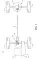
- FIG. 1 illustrates an exemplary vehicle drive train assembly 10 for transferring torque to first or main set of wheels 12 and a second or secondary set of wheels 14 of a vehicle.
- the drive train assembly 10 includes a main or front driveline 16 and a secondary or rear driveline 18.
- the front driveline 16 includes, among other components, an engine 20, a transmission 22 and a power take off unit 24 (PTU).
- the PTU 24 includes an output 26 to transmit torque through a propeller shaft 28 to secondary drive unit and specifically a rear drive unit 30 (RDU) for driving the rear wheels 14.
- the RDU 30 includes a twin clutch assembly according to the present disclosure.
- a controller (not shown) is in communication with the components in the front driveline 16 and rear driveline 18 and also in communication with one or more sensors located throughout the vehicle. The controller is also configured to control the hydraulic system for activating the pistons and twin clutch assemblies as described herein.
- FIG. 2 illustrates a twin clutch assembly 200 as known in the prior art for a rear drive unit 202.
- Torque flows from the pinion gear 204 to the ring gear 206 and then directly to the left and right clutch housings 208, 210 since they are directly connected.
- Left and right pistons 212, 214 control the apply pressure on the left and right clutch plates 216, 218 thus independently controlling left and right output torque.
- the left and right pistons 212, 214 can be made so that the clearance is large enough to separate the clutch plates 216, 218 so that the left and right output shafts 220, 222 and the respective clutch housings 208, 210 become disconnected.
- the pinion gear 204 and ring gear 206 will stop rotating.
- the pistons 212, and or 214 will modulate enough torque in a controlled manner so that the system is connected smoothly.
- the assembly 301 is contained within the housing 302 of the RDU 30 and is situated on one side of a drive source for the secondary axle.
- the RDU housing 302 defines a first compartment or section 304 which receives the drive source.
- the RDU housing 302 defines a second compartment or section 305 which contains the twin clutch assembly 301.
- the drive source is a pinion gear 306 and pinion shaft 307 which are operatively coupled to the propeller shaft 28 and PTU 24 of the vehicle.
- the pinion gear 306 is coupled with a ring gear 308 having a main shaft 309 which is received in the section 304.
- the second section 305 and assembly 301 are located to the right of the first section 304 of the RDU housing 302. In other embodiments (not shown), a symmetrical or mirror image version of the assembly 301 and second section 305 are located to the left of the drive source and first section 304. In contrast to the twin clutch assembly 200 in Figure 2 , which includes separate right and left clutch assemblies on each side of the drive source, the twin clutch assembly 301 according to the present disclosure is located on one side of the drive source.
- the twin clutch assembly 301 includes a common clutch housing 310, a left clutch 312 and a right clutch 314.
- the clutch housing 310 is connected to the main shaft 309.
- a right output shaft 316 is piloted and supported by a left output shaft 318.
- the left output shaft 318 is piloted and supported by the right output shaft 316.
- the left output shaft 318 is concentric and coupled within the main shaft 310.
- the left output shaft 318 extends from the twin clutch assembly 301, through the main shaft 309, to the left rear wheel.
- differential motion is carried out by right and left outputs shafts 316, 318 being piloted together with a bearing or bushing 320.
- the right and left outputs shafts 316, 318 are piloted together with an "L" shaped sintered bearing.
- Each clutch 312, 314 includes respective sets of left and right separator plates, sets of left and right friction disks, and at least two piston assemblies for activating the clutch.
- each of the left and right clutch assemblies includes respective sets of left and right separator plates 324, 326 which are integrated into the clutch housing 310.
- the clutch housing 310 is splined to of the sets of left and right separator plates 324, 326.
- the left output shaft 318 carries a set of friction disks 328 for the left clutch 312 and the right output shaft 316 carries a set of friction disks 330 for the right clutch 314.
- the left and right clutches 312, 314 are actuated by respective pairs of left and right hydraulic piston assemblies, 334, 336. Thus, independent torque biasing is enabled.
- the twin clutch assembly 301 includes a centre plate 340 which separates the set of left separator plates 324 and the set of right separator plates 326 in order to support independent left and right torque control.
- the centre plate 340 is stiff enough to carry the thrust load from the pistons 334, 336. Specifically, the centre plate 340 is stiff enough to react against the actuation force from either side of the clutch assembly 301 to avoid the plate 340 deflecting and compressing the clutch plates in the other side of the assembly 301.
- the centre plate 340 is rigidly fixed to the clutch housing 310.
- the left piston assembly 334 actuate the left clutch 312 via an external apply plate 342.
- the external apply plate 342 may be mated to the side of the clutch housing 310 through windows or apertures (not shown) to squeeze the clutch plates inside.
- the right piston assembly 336 actuates the right clutch 314through one of the clutch plates, as described below.
- the friction disks 328, 330 and separator plates 324, 326 are spaced apart to cause a disconnect between the ring gear 308 and left and right output shafts 316, 318.
- the ring gear 308 is synchronized to approximately the same relative speed as the rear wheels 14. Torque is generated to overcome the inertial torque to spin the ring gear 308, the pinion shaft 307 and the propeller shaft 28 to the same relative speed of the vehicle. This can be accomplished by engaging either one of the left and right clutches 312, 314 at the same time or in serial fashion.
- the speed of synchronization will depend on how quickly the clearance gap is taken up by one or both of the left and right clutches 312, 314 and the torque response of the actuator to produce torque in the clutches 312, 314.
- the self contained clutch assembly 301 has a smaller overall size and enables an actuator system to be placed near the assembly 301, resulting in shorter overall fluid porting to both left and right hydraulic piston assemblies. Thus, a faster responding AWD system may be achieved.
- both clutches 312, 314 could be utilized to start the synchronization process, depending on the torque required.
- the left and right hydraulic piston assemblies 334, 336 are provided with symmetrical geometries and cavity sizes and thus each piston has a similar response or performance.
- the torque level to synchronize the driveline is relatively small as compared to the capacity of the left and right clutches 312, 314, just one of the clutches is used to synchronize the driveline.
- the right hydraulic piston assembly 336 is configured as a dual action piston according to one embodiment of the present disclosure. Since only one clutch may be needed to synchronize the driveline, the dual action piston assembly 336 is configured to engage the right clutch 314 or "synchronizing clutch" more quickly than the "non-synchronizing" left clutch 312.
- the dual action piston assembly 336 includes a dual action piston 349 received or mounted a first cavity defined in a first inward facing wall 350 of the RDU housing 302.
- the dual action piston 349 and the first cavity define two chambers, CH1 and CH2, for receiving fluid for actuating the piston assembly 336.
- the two chambers CH1 and CH2 are spaced apart linearly within the cavity for the dual action piston assembly 336 and are defined by the piston 349 having a generally "H" shaped cross-section.
- the non-dual action left piston assembly 334 includes a piston 351 received or mounted in a second cavity defined in a second inward facing wall 352 of the RDU housing 302.
- the piston 352 and the second cavity define a third chamber CH3 for receiving fluid for actuating the piston assembly 334.
- a bias means (not shown in Figure 3 ) is provided to return the pistons 349, 351 to their retracted positions.
- Bearings (not shown in Figure 3 ) also may be placed between the piston assemblies 334, 336 and the apply plate 342 and right separator plates 326.
- the overall volume of chamber CH1 is less than the volume of CH2 and it is also less than the volume of chamber CH3 for the left piston assembly 334.
- the right piston 349 moves faster when the filling rate is the same for both piston assemblies. Since the reaction torque to synchronize the driveline is relatively small, only one clutch and the partial piston surface area of the dual action piston assembly 336 can be used with a faster response time as a result.
- the piston assembly 336 performs dual functions by quickly overcoming the clearance and synchronizing the right clutch 314 while at the same time chamber CH2 is filled. Chambers CH2 and CH3for piston assemblies 336, 334 may be equally sized so that the left and right pistons 351, 349 will push with the same force during primary torque control.
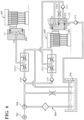
- FIG. 4 An RDU 400 and twin clutch assembly 401 according to another embodiment of the present disclosure is illustrated in Figure 4 .
- the assembly 401 is similar to the assembly 301 shown in Figure 3 but includes a different configuration of the RDU housing 402 and a different embodiment of a dual action piston assembly 412 for the right clutch 415.
- a different embodiment of the non-dual action piston assembly 414 is also provided for the left clutch 413.
- the dual action piston assembly 412 includes a dual action piston 416 received or mounted a first cavity defined in the first inward facing wall 350 of the RDU housing 401.
- the dual action piston 416 and the first cavity define two chambers, C1 and C2, for receiving fluid for actuating the dual action piston assembly 412.
- the two chambers C1 and C2 are staggered or spaced apart axially and radially within the cavity and are defined by the piston 416 having a stepped cross-section.
- the non-dual action left piston assembly 414 includes a piston 418 received or mounted in a second cavity defined in a second inward facing wall 352 of the RDU housing 402.
- the piston 416 and the second cavity define a chamber C3 for receiving fluid for actuating the piston assembly 414.
- the twin clutch assembly 401 includes bias means to return the pistons 416, 418 to their retracted or disconnected positions.
- Example bias means are shown in Figure 4 with right and left springs 422, 420engaging the pistons 416, 418 and portions of the RDU housing 402. Bearings also may be placed between the piston assemblies 412, 412 and the apply plate 342 and right separator plates 326.
- the volume of chamber C1 is less than the volume of C2 and only one clutch and the partial piston surface area of the dual action piston assembly 412 can be used for synchronization with a faster response time as a result.
- chambers C1 and C2 have the same pressure apply area as the non-dual action left piston assembly 414 with chamber C3 so that the left and right pistons 418, 416 will push with the same force during primary torque control.
- each piston assembly 334, 336, 412, 414 may vary and the ratio of the chamber sizes, orifice sizes, porting diameters, valve clearances and pump flow rates are configured to maximize piston stroke response.
- the dual action piston assembly is shown for the right clutch in Figures 3 and 4 , in other embodiments, the left piston assembly may be configured as a synchronizing, dual action piston and the right piston assembly may be a non-synchronizing, non-dual action piston. In other embodiments, both the left and right piston assemblies may be configured as a synchronizing, dual action piston. It will also be appreciated that the dual action piston assemblies according to the present disclosure also may be used in other disconnecting clutch systems, such as the assembly shown in Figure 2 .
- a controller activates an electric motor 512 in the hydraulic control system 510.
- the controller may be part of the vehicle controller or a standalone system.
- the motor 512 spins an electric pump 514 to generate hydraulic pressure.
- the motor 512 operates at a fixed speed resulting in the pump 514 providing a fixed flow rate.
- the pump 514 forces hydraulic fluid from a reservoir 516 through a one-way check valve CV1 into a linear solenoid valve LSV1 which is also controlled electronically by the controller.
- Hydraulic fluid flows from the valve LSV1 through a dedicated port P1 into the chamber C1 of the right or dual action piston assembly 412.
- Chamber C1 is filled with fluid under pressure and as a result, the piston 416 moves more rapidly since a smaller cavity, relative to chamber C3 for piston assembly 414, is being filled.
- the force applied by the piston 416 to the outer separator plate of the right clutch 415 is sufficient to synchronize the driveline components.
- the reaction torque to synchronize the driveline is relatively small, only the right clutch 415 and a partial piston surface area of the dual action piston assembly 412 are used at this stage. This results in a faster response time for synchronizing and ultimately engaging the driveline components for AWD operation.
- chamber C2 While the dual action piston 416 moves towards the right separator plates 326 (to the left in Figure 4 ), a negative pressure or vacuum is created in chamber C2 which causes chamber C2 to be filled as it draws fluid from the reservoir 516 through a one way check valve CV2 and input port P2. Although a second input port P3 IN is provided for chamber C2, this port is configured with a smaller orifice. Thus, as the chamber C1 is being filled, limited fluid flows into chamber C2 through port P3 IN.
- the piston cavity ratio, C1 vs. C2, orifice size, porting diameters, valve clearances and pump flow rates are configured to ensure that the piston stroke response is maximized.
- Chambers C1 and C2 and the piston 416 are configured such that once the piston 416 has moved through its complete stroke, to a contact point or kiss point (clutch clearance take up) of the right clutch 415, both chambers C1 and C2 are filled and are at equal pressure. At the kiss point, equal pressure is supplied to chambers C1, C2 through ports P1 and P3 IN, respectively. Although the orifice of P3 IN is restricted, it is sufficiently sized to enable pressure control in chamber C2 for torque modulation. Pressure relief from chamber C2 is provided by a one way check valve CV3 through port P3 EX to a drain port of the LSV1. Pressure relief from chamber C1 is provided through a drain port of the LSV1.
- Figure 7 is a graph illustrating pressures in the chambers C1 and C2 during this process.
- the upper line 710 of the graph shows the primary piston pressure for chamber C1.
- the secondary piston pressure for chamber C2 is indicated by the dashed lower line 712 of the graph and this shows the negative pressure initially created in chamber C2.
- the time t denotes the time for the dual action piston 416 to engage the right clutch 415 and take up or overcome the clearance between the friction disks 330 and separator plates 326.
- the pressure in chamber C1 is initially larger in order to quickly overcome or take up the clearance between the clutch plates in the right clutch 415. Pressure is reduced as the right clutch 415 nears the kiss point.
- torque modulation is achieved by controlling the pressures in chambers C1 and C2 through ports P1 and P3 IN.
- the controller activates the left piston assembly 414 through the control of linear solenoid valve LSV2. Specifically, the pump 514 forces hydraulic fluid from the reservoir 516 through a one way check valve CV4 into LSV2. Hydraulic fluid flows from the valve LSV2 through a dedicated port P4 into the chamber C3 of the left or non-dual action piston assembly 414. Pressure relief from chamber C3 is provided through a drain port of the valve LSV1.
- FIG. 8 illustrates an example time line and such overlap for one embodiment.
- the synchronization time for the rotation of the propeller shaft 28 may start after the right clutch 415 reaches the kiss point and may overlap with the activation of the left clutch 413.
- the PTU engagement also may overlap with the synchronization for the rotation of the propeller shaft 28 and the activation of the left clutch 413 to its clearance point.
- the controller operates the linear solenoid valves LSV1 and LSV2 to drain or bleed out fluid from chambers C1, C2 and C3 through ports P1, P3 EX and P4, respectively.
- the left and right pistons 418, 416 retract back to an open or disconnected position.
- the left and right pistons 418, 416 are urged back to the open or disconnected position by a bias means such as the springs 420, 422, as illustrated in Figure 4 .
- the controller activates an electric motor 912 and controls linear solenoid valves LSV1, LSV2 in the hydraulic control system 910.
- the motor 912 spins an electric pump 914 to generate hydraulic pressure.
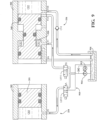
- the pump 914 forces hydraulic fluid from a reservoir 916 through valves LSV1 and LSV2 and ports P1 and P3 to fill chambers CH1 and CH3.
- Port P2A for chamber CH2 is blocked during this process by the piston 349.
- a negative pressure or vacuum is created in chamber CH2 which causes chamber CH2 to be filled as it draws fluid from the reservoir 916 through a one way check valve CV1 and port P2B.
- the right piston 351 moves more quickly than the left piston 349 since the size of CH1 is less than the size of CH3.
- the right piston 349 moves the right clutch 314 to the kiss point to start synchronization.
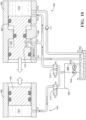
- port P2A is opened and chamber CH2 is filled completely.
- an axial valve 920 in the chamber CH1 closes port P1 and port P4 is opened.
- the one way check valve CV1 prevents fluid from backing out of chamber CH2 through port P5.
- Either the left or the right piston assembly can be a dual action piston and initially made to move faster than the other with the same supply pressure to both right and left sides. Therefore the synchronization (from an open piston to the kiss point or standby mode) can happen more quickly without any additional moving parts.
- One piston assembly is made to have a dual role by adding two cavities with which the piston is controlled.
- the dual action piston assembly 336 also fills chamber CH1 under pressure and chamber CH2 under vacuum due to the moving piston so that both chambers are filling under the leftward movement of the piston 349. Since chambers CH2 and CH3 are of equal size, and are controlled and configured to fill at relatively the same rate, this ensures that primary piston pressure for primary torque control is available at the same time.
- the controller operates the linear solenoid valves LSV1 and LSV2 to drain or bleed out fluid from chambers CH2 and CH3 through ports P2A and P3, respectively.
- the left and right pistons 351, 349 retract back to an open or disconnected position.
- the left and right pistons 351, 349 are urged back to the open or disconnected position by a bias means such as springs.
Landscapes
- Engineering & Computer Science (AREA)
- General Engineering & Computer Science (AREA)
- Mechanical Engineering (AREA)
- Chemical & Material Sciences (AREA)
- Combustion & Propulsion (AREA)
- Transportation (AREA)
- Hydraulic Clutches, Magnetic Clutches, Fluid Clutches, And Fluid Joints (AREA)
- Arrangement And Mounting Of Devices That Control Transmission Of Motive Force (AREA)
- Arrangement And Driving Of Transmission Devices (AREA)
- Retarders (AREA)
Description
- This application claims priority to
U.S. provisional patent application No. 62/398,164, filed September 22, 2016 - The present invention relates to a twin clutch system for a secondary axle of an all wheel drive vehicle and a hydraulic torque actuator with a dual action piston.
- Hydraulic torque actuation is commonly used on a secondary axle on a front or rear wheel drive vehicle where all wheel drive is an option. This may be for both permanent active on demand systems (AOD) as well as disconnecting systems where the ring gear and pinion are stopped when the all wheel drive function is not needed. On a side mounted twin clutch axle, where independent torque control of left and right wheels is offered, each left and right mounted clutch has an actuator typically consisting of an independent piston where pressure modulation determines the thrust force and therefore the torque setting.
- Reference is made to patent document
JP 2006 182242 A - Reference is made to patent document
US 5 964 126 A , which relates to a prior art hydraulic coupling for an auxiliary drive axle of a vehicle drivetrain. - Reference is made to
patent document EP 1 279 546 A2 , which relates to a prior art coupling device for coupling an input shaft to an output shaft of a vehicle. - Reference is made to patent document
US 3 352 395 A , which relates to a prior art friction clutch having centrifugally operated valves. - Reference is made to patent document
US 9 284 993 B1 - Reference is made to patent document
WO 2015/159955 A1 , which relates to a prior art dual clutch device for connecting and disconnecting the transmission of power from an engine to first and second transmission input shafts. - Reference is made to patent
US 2013/199883 A1 , which relates to a prior art power transmission device having left and right clutch pistons. - According to the invention there is provided a secondary drive unit for an all wheel drive vehicle having left and right secondary drive wheels which are selectively connected to a drive source through the secondary drive unit, the secondary drive unit housing a main shaft operatively coupled to the drive source. The secondary drive unit includes a secondary drive unit (SDU) housing, the housing defining a first section for receiving the main shaft, and the housing defining a second section for enclosing a twin clutch assembly, a left output shaft concentric with the main shaft, the left output shaft for transferring torque to the left secondary drive wheel; and a right output shaft coaxial with the left output shaft, the right output shaft for transferring torque to the right secondary drive wheel. The twin clutch assembly includes a clutch housing connected to the main shaft, a left clutch for selectively connecting the left output shaft and the clutch housing, a right clutch for selectively connecting the right output shaft and the clutch housing, and a rigid center plate extending from an inner wall of the clutch housing, the rigid center plate separating the left and right clutches. One of the right or left clutches further includes a dual action piston assembly. The dual action piston assembly includes a dual action piston, a cavity defined in a first inward facing wall of the SDU housing for receiving the dual action piston, and first and second ports defined in the SDU housing for passing fluid to activate the dual action piston assembly. The dual action piston and the cavity in the first inward facing wall define first and second chambers for receiving fluid through the first and second ports and the first chamber has a volume less than a volume of the second chamber.
- In some embodiments, the second section of the SDU housing is located wholly on one side of the first section of the SDU housing. In some embodiments the right output shaft is piloted and supported by the left output shaft.
- In some embodiments, the right clutch may include a set of right separator plates integrated into the clutch housing and interleaved with a set of right friction disks carried by the right output shaft. The left clutch may include a set of left separator plates integrated into the clutch housing and interleaved with a set of left friction disks carried by the left output shaft. The sets of left and right separator plates are separated by the center plate and the sets of left and right friction disks are separated by the center plate.
- In some embodiments, as fluid is received through the first port for activation of the dual action piston assembly, fluid is drawn by the dual action piston assembly into the second port and second chamber.
- In some embodiments the dual action piston has a generally H-shaped cross-section. In some embodiments the dual action piston has a generally stepped cross-section.
- In some embodiments, the other of the right or left clutches further includes a non-dual action piston assembly, the non-dual action piston assembly includes a non-dual action piston, a cavity defined in a second inward facing wall of the SDU housing for receiving the non-dual action piston, and a third port defined in the SDU housing for passing fluid to activate the non-dual action piston assembly, the non-dual action piston and the cavity in the second inward facing wall defining a third chamber for receiving fluid through the third port.
- In some embodiments, the volume of the first chamber of the dual action piston assembly is less than a volume of the third chamber of the non-dual action piston assembly. In some embodiments, the first and second chambers of the dual action piston assembly have substantially the same pressure apply area as the third chamber of the non-dual action piston assembly.
- Reference will now be made, by way of example, to the accompanying drawings which show example embodiments of the present application, and in which:
-
Figure 1 illustrates a vehicle drive train having a rear axle twin clutch system according to an embodiment of the present invention ; -
Figure 2 illustrates a cross-section view of a portion of a rear drive unit and twin clutch system as known in the prior art; -
Figure 3 illustrates a cross-section view of a portion of a rear drive unit and twin clutch system according to a one embodiment of the present invention ; -
Figure 4 is a cross-section view of a portion of a rear drive unit and twin clutch system according to another embodiment of the present invention ; -
Figure 5 is a diagram illustrating the operation of a hydraulic control system and the dual action piston shown inFigure 4 ; -
Figure 6 is a schematic diagram illustrating the hydraulic control system; -
Figure 7 is a graph illustrating pressures in dual action piston according to one embodiment of the present invention ; -
Figure 8 is a graph illustrating synchronization response times for vehicle driveline components according to one embodiment of the present invention ; and -
Figures 9 and10 are diagrams illustrating two stages of the operation of a hydraulic control system for the dual action piston assemblies shown inFigure 3 . - Similar reference numerals may have been used in different figures to denote similar components.
- The present application is directed to a twin clutch system for a secondary axle on a front or rear wheel drive vehicle which also supports all wheel drive. A dual action piston and methods for actuation of the twin clutch system are also provided. While described and illustrated with reference to the rear axle of a front wheel drive vehicle, the twin clutch system and dual action piston may be used for any secondary axle.
-
Figure 1 illustrates an exemplary vehicledrive train assembly 10 for transferring torque to first or main set ofwheels 12 and a second or secondary set ofwheels 14 of a vehicle. Thedrive train assembly 10 includes a main orfront driveline 16 and a secondary orrear driveline 18. Thefront driveline 16 includes, among other components, anengine 20, atransmission 22 and a power take off unit 24 (PTU). The PTU 24 includes anoutput 26 to transmit torque through apropeller shaft 28 to secondary drive unit and specifically a rear drive unit 30 (RDU) for driving therear wheels 14. TheRDU 30 includes a twin clutch assembly according to the present disclosure. A controller (not shown) is in communication with the components in thefront driveline 16 andrear driveline 18 and also in communication with one or more sensors located throughout the vehicle. The controller is also configured to control the hydraulic system for activating the pistons and twin clutch assemblies as described herein. -
Figure 2 illustrates atwin clutch assembly 200 as known in the prior art for arear drive unit 202. Torque flows from thepinion gear 204 to thering gear 206 and then directly to the left andright clutch housings right pistons right clutch plates right pistons clutch plates right output shafts respective clutch housings pinion gear 204 andring gear 206, as well as thepropeller shaft 28 will stop rotating. When the need to connect the driveline arises, thepistons - Separate left and right clutches pose some challenges, however, in terms of having two clutch housings, separate output shafts with their own bearing supports, and increased width and potentially weight. In addition, sufficient clearance between the clutch plates is needed to reduce parasitic loses during the disconnecting state and provide a low drag when the system is in a disconnected state. The response time, however, from when the clutch is completely open to closing the clearance and starting torque control may be longer than desirable for a dynamic, fast responding AWD system.
- An
RDU 30 and twinclutch assembly 301 according to one embodiment of the present disclosure are illustrated inFigure 3 . Theassembly 301 is contained within thehousing 302 of theRDU 30 and is situated on one side of a drive source for the secondary axle. Specifically, theRDU housing 302 defines a first compartment orsection 304 which receives the drive source. TheRDU housing 302 defines a second compartment orsection 305 which contains the twinclutch assembly 301. In one embodiment, the drive source is apinion gear 306 andpinion shaft 307 which are operatively coupled to thepropeller shaft 28 andPTU 24 of the vehicle. Thepinion gear 306 is coupled with aring gear 308 having amain shaft 309 which is received in thesection 304. In the embodiment shown inFigure 3 , thesecond section 305 andassembly 301 are located to the right of thefirst section 304 of theRDU housing 302. In other embodiments (not shown), a symmetrical or mirror image version of theassembly 301 andsecond section 305 are located to the left of the drive source andfirst section 304. In contrast to the twinclutch assembly 200 inFigure 2 , which includes separate right and left clutch assemblies on each side of the drive source, the twinclutch assembly 301 according to the present disclosure is located on one side of the drive source. - The twin
clutch assembly 301 includes a commonclutch housing 310, aleft clutch 312 and aright clutch 314. Theclutch housing 310 is connected to themain shaft 309. Aright output shaft 316 is piloted and supported by aleft output shaft 318. In other embodiments, theleft output shaft 318 is piloted and supported by theright output shaft 316. Theleft output shaft 318 is concentric and coupled within themain shaft 310. Although not extended inFigure 3 , theleft output shaft 318 extends from the twinclutch assembly 301, through themain shaft 309, to the left rear wheel. When theclutch assembly 301 is connected to provide AWD, theright output shaft 316 transfers torque to the right rear wheel and theleft output shaft 318 transfers torque to the left rear wheel. Depending on the amount of slip required between left and right clutch plates, differential motion is carried out by right and leftoutputs shafts bushing 320. In one embodiment, the right and leftoutputs shafts - Each clutch 312, 314 includes respective sets of left and right separator plates, sets of left and right friction disks, and at least two piston assemblies for activating the clutch. Specifically, each of the left and right clutch assemblies includes respective sets of left and
right separator plates clutch housing 310. In one embodiment, theclutch housing 310 is splined to of the sets of left andright separator plates left output shaft 318 carries a set offriction disks 328 for theleft clutch 312 and theright output shaft 316 carries a set offriction disks 330 for theright clutch 314. The left andright clutches - The twin
clutch assembly 301 includes acentre plate 340 which separates the set ofleft separator plates 324 and the set ofright separator plates 326 in order to support independent left and right torque control. Thecentre plate 340 is stiff enough to carry the thrust load from thepistons centre plate 340 is stiff enough to react against the actuation force from either side of theclutch assembly 301 to avoid theplate 340 deflecting and compressing the clutch plates in the other side of theassembly 301. In one embodiment, thecentre plate 340 is rigidly fixed to theclutch housing 310. In one embodiment, theleft piston assembly 334 actuate theleft clutch 312 via an external applyplate 342. The external applyplate 342 may be mated to the side of theclutch housing 310 through windows or apertures (not shown) to squeeze the clutch plates inside. Theright piston assembly 336 actuates the right clutch 314through one of the clutch plates, as described below. - In two wheel drive (2WD) mode, the
friction disks separator plates ring gear 308 and left andright output shafts ring gear 308 is synchronized to approximately the same relative speed as therear wheels 14. Torque is generated to overcome the inertial torque to spin thering gear 308, thepinion shaft 307 and thepropeller shaft 28 to the same relative speed of the vehicle. This can be accomplished by engaging either one of the left andright clutches right clutches clutches PTU 24 is connected, torque modulation can take place. - The self contained
clutch assembly 301 has a smaller overall size and enables an actuator system to be placed near theassembly 301, resulting in shorter overall fluid porting to both left and right hydraulic piston assemblies. Thus, a faster responding AWD system may be achieved. In one embodiment, bothclutches hydraulic piston assemblies right clutches - As illustrated in
Figure 3 , to further improve the synchronization and AWD connection response time, the righthydraulic piston assembly 336 is configured as a dual action piston according to one embodiment of the present disclosure. Since only one clutch may be needed to synchronize the driveline, the dualaction piston assembly 336 is configured to engage theright clutch 314 or "synchronizing clutch" more quickly than the "non-synchronizing" leftclutch 312. The dualaction piston assembly 336 includes adual action piston 349 received or mounted a first cavity defined in a first inward facingwall 350 of theRDU housing 302. Thedual action piston 349 and the first cavity define two chambers, CH1 and CH2, for receiving fluid for actuating thepiston assembly 336. In the embodiment shown inFigure 3 , the two chambers CH1 and CH2 are spaced apart linearly within the cavity for the dualaction piston assembly 336 and are defined by thepiston 349 having a generally "H" shaped cross-section. The non-dual action leftpiston assembly 334 includes apiston 351 received or mounted in a second cavity defined in a second inward facingwall 352 of theRDU housing 302. Thepiston 352 and the second cavity define a third chamber CH3 for receiving fluid for actuating thepiston assembly 334. A bias means (not shown inFigure 3 ) is provided to return thepistons Figure 3 ) also may be placed between thepiston assemblies plate 342 andright separator plates 326. - In one embodiment of the dual
action piston assembly 336, the overall volume of chamber CH1 is less than the volume of CH2 and it is also less than the volume of chamber CH3 for theleft piston assembly 334. As a result, as described below, theright piston 349 moves faster when the filling rate is the same for both piston assemblies. Since the reaction torque to synchronize the driveline is relatively small, only one clutch and the partial piston surface area of the dualaction piston assembly 336 can be used with a faster response time as a result. Thepiston assembly 336 performs dual functions by quickly overcoming the clearance and synchronizing theright clutch 314 while at the same time chamber CH2 is filled. Chambers CH2 andCH3for piston assemblies right pistons - An
RDU 400 and twinclutch assembly 401 according to another embodiment of the present disclosure is illustrated inFigure 4 . Theassembly 401 is similar to theassembly 301 shown inFigure 3 but includes a different configuration of theRDU housing 402 and a different embodiment of a dualaction piston assembly 412 for theright clutch 415. A different embodiment of the non-dualaction piston assembly 414 is also provided for theleft clutch 413. - The dual
action piston assembly 412 includes adual action piston 416 received or mounted a first cavity defined in the first inward facingwall 350 of theRDU housing 401. Thedual action piston 416 and the first cavity define two chambers, C1 and C2, for receiving fluid for actuating the dualaction piston assembly 412. In the embodiment shown inFigure 4 , the two chambers C1 and C2 are staggered or spaced apart axially and radially within the cavity and are defined by thepiston 416 having a stepped cross-section. The non-dual action leftpiston assembly 414 includes apiston 418 received or mounted in a second cavity defined in a second inward facingwall 352 of theRDU housing 402. Thepiston 416 and the second cavity define a chamber C3 for receiving fluid for actuating thepiston assembly 414. The twinclutch assembly 401 includes bias means to return thepistons Figure 4 with right and leftsprings 422, 420engaging thepistons RDU housing 402. Bearings also may be placed between thepiston assemblies plate 342 andright separator plates 326. - In this embodiment, the volume of chamber C1 is less than the volume of C2 and only one clutch and the partial piston surface area of the dual
action piston assembly 412 can be used for synchronization with a faster response time as a result. Collectively, chambers C1 and C2 have the same pressure apply area as the non-dual action leftpiston assembly 414 with chamber C3 so that the left andright pistons - The sizes and geometries of the chambers for each
piston assembly Figures 3 and4 , in other embodiments, the left piston assembly may be configured as a synchronizing, dual action piston and the right piston assembly may be a non-synchronizing, non-dual action piston. In other embodiments, both the left and right piston assemblies may be configured as a synchronizing, dual action piston. It will also be appreciated that the dual action piston assemblies according to the present disclosure also may be used in other disconnecting clutch systems, such as the assembly shown inFigure 2 . - The operation of the twin
clutch assembly 401 will be described first with reference to the illustration of thepiston assemblies hydraulic control system 510 and hydraulic schematic inFigures 5 and6 . Starting from a disconnected state, a controller (not shown) activates anelectric motor 512 in thehydraulic control system 510. The controller may be part of the vehicle controller or a standalone system. Themotor 512 spins anelectric pump 514 to generate hydraulic pressure. In one embodiment, themotor 512 operates at a fixed speed resulting in thepump 514 providing a fixed flow rate. Thepump 514 forces hydraulic fluid from areservoir 516 through a one-way check valve CV1 into a linear solenoid valve LSV1 which is also controlled electronically by the controller. Hydraulic fluid flows from the valve LSV1 through a dedicated port P1 into the chamber C1 of the right or dualaction piston assembly 412. Chamber C1 is filled with fluid under pressure and as a result, thepiston 416 moves more rapidly since a smaller cavity, relative to chamber C3 forpiston assembly 414, is being filled. The force applied by thepiston 416 to the outer separator plate of theright clutch 415 is sufficient to synchronize the driveline components. In other words, since the reaction torque to synchronize the driveline is relatively small, only theright clutch 415 and a partial piston surface area of the dualaction piston assembly 412 are used at this stage. This results in a faster response time for synchronizing and ultimately engaging the driveline components for AWD operation. - While the
dual action piston 416 moves towards the right separator plates 326 (to the left inFigure 4 ), a negative pressure or vacuum is created in chamber C2 which causes chamber C2 to be filled as it draws fluid from thereservoir 516 through a one way check valve CV2 and input port P2. Although a second input port P3 IN is provided for chamber C2, this port is configured with a smaller orifice. Thus, as the chamber C1 is being filled, limited fluid flows into chamber C2 through port P3 IN. The piston cavity ratio, C1 vs. C2, orifice size, porting diameters, valve clearances and pump flow rates are configured to ensure that the piston stroke response is maximized. Chambers C1 and C2 and thepiston 416 are configured such that once thepiston 416 has moved through its complete stroke, to a contact point or kiss point (clutch clearance take up) of theright clutch 415, both chambers C1 and C2 are filled and are at equal pressure. At the kiss point, equal pressure is supplied to chambers C1, C2 through ports P1 and P3 IN, respectively. Although the orifice of P3 IN is restricted, it is sufficiently sized to enable pressure control in chamber C2 for torque modulation. Pressure relief from chamber C2 is provided by a one way check valve CV3 through port P3 EX to a drain port of the LSV1. Pressure relief from chamber C1 is provided through a drain port of the LSV1. -
Figure 7 is a graph illustrating pressures in the chambers C1 and C2 during this process. Theupper line 710 of the graph shows the primary piston pressure for chamber C1. The secondary piston pressure for chamber C2 is indicated by the dashedlower line 712 of the graph and this shows the negative pressure initially created in chamber C2. The time t denotes the time for thedual action piston 416 to engage theright clutch 415 and take up or overcome the clearance between thefriction disks 330 andseparator plates 326. The pressure in chamber C1 is initially larger in order to quickly overcome or take up the clearance between the clutch plates in theright clutch 415. Pressure is reduced as theright clutch 415 nears the kiss point. After that stage, once the driveline components are synchronized, torque modulation is achieved by controlling the pressures in chambers C1 and C2 through ports P1 and P3 IN. - In one embodiment, once the
right clutch 415 has provided enough torque to synchronize the driveline components, the controller activates theleft piston assembly 414 through the control of linear solenoid valve LSV2. Specifically, thepump 514 forces hydraulic fluid from thereservoir 516 through a one way check valve CV4 into LSV2. Hydraulic fluid flows from the valve LSV2 through a dedicated port P4 into the chamber C3 of the left or non-dualaction piston assembly 414. Pressure relief from chamber C3 is provided through a drain port of the valve LSV1. Once both left andright piston assemblies propeller shaft 28, and the connection in thePTU 24 can be realized in order to improve the total system response.Figure 8 illustrates an example time line and such overlap for one embodiment. As shown, the synchronization time for the rotation of thepropeller shaft 28 may start after theright clutch 415 reaches the kiss point and may overlap with the activation of theleft clutch 413. The PTU engagement also may overlap with the synchronization for the rotation of thepropeller shaft 28 and the activation of theleft clutch 413 to its clearance point. - For the twin
clutch assembly 401 to return to a disconnected state, the controller operates the linear solenoid valves LSV1 and LSV2 to drain or bleed out fluid from chambers C1, C2 and C3 through ports P1, P3 EX and P4, respectively. The left andright pistons right pistons springs Figure 4 . - Alternative synchronization and engagement sequences may be implemented depending on the arrangement of the dual action piston assembly and the desired performance of the twin clutch assembly. The operation of the embodiment of the
clutch assembly 301 ofFigure 3 is described with reference to the illustration of thepiston assemblies hydraulic control system 910 inFigures 9 and10 . Again, the apply principle is accomplished in two stages. The first is to move theright clutch 314 to the kiss point and synchronization and the second is torque modulation by using the respective filled chambers.Figure 9 represents a starting point from a disconnected state andFigure 10 represents the state of thepiston assemblies hydraulic control system 910 at the kiss point. - Specifically in
Figure 9 , starting from a disconnected state, the controller activates an electric motor 912 and controls linear solenoid valves LSV1, LSV2 in thehydraulic control system 910. The motor 912 spins anelectric pump 914 to generate hydraulic pressure. Thepump 914 forces hydraulic fluid from areservoir 916 through valves LSV1 and LSV2 and ports P1 and P3 to fill chambers CH1 and CH3. Port P2A for chamber CH2 is blocked during this process by thepiston 349. As thedual action piston 349 moves towards the right separator plates 326 (to the left inFigure 9 ), a negative pressure or vacuum is created in chamber CH2 which causes chamber CH2 to be filled as it draws fluid from thereservoir 916 through a one way check valve CV1 and port P2B. Although all three chambers CH1, CH2, CH3 are being filled in this embodiment, theright piston 351 moves more quickly than theleft piston 349 since the size of CH1 is less than the size of CH3. Thus, theright piston 349 moves theright clutch 314 to the kiss point to start synchronization. - As shown in
Figure 10 , as theright piston 349 completes its stroke, port P2A is opened and chamber CH2 is filled completely. Also as port P2A opens, anaxial valve 920 in the chamber CH1 closes port P1 and port P4 is opened. As a result, at the kiss point, fluid from chamber CH1 discharges back into thereservoir 916. The one way check valve CV1 prevents fluid from backing out of chamber CH2 through port P5. Thus, during torque modulation, fluid in chamber CH1 is discharged to thereservoir 916 through P4 so that the left andright piston assemblies - Either the left or the right piston assembly can be a dual action piston and initially made to move faster than the other with the same supply pressure to both right and left sides. Therefore the synchronization (from an open piston to the kiss point or standby mode) can happen more quickly without any additional moving parts. One piston assembly is made to have a dual role by adding two cavities with which the piston is controlled. The dual
action piston assembly 336 also fills chamber CH1 under pressure and chamber CH2 under vacuum due to the moving piston so that both chambers are filling under the leftward movement of thepiston 349. Since chambers CH2 and CH3 are of equal size, and are controlled and configured to fill at relatively the same rate, this ensures that primary piston pressure for primary torque control is available at the same time. - For the twin
clutch assembly 301 to return to a disconnected state, the controller operates the linear solenoid valves LSV1 and LSV2 to drain or bleed out fluid from chambers CH2 and CH3 through ports P2A and P3, respectively. The left andright pistons right pistons
Claims (10)
- A secondary drive unit (30) for an all wheel drive vehicle having left and right secondary drive wheels (14) which are selectively connected to a drive source through the secondary drive unit, the secondary drive unit (30) housing a main shaft (309) operatively coupled to the drive source, the secondary drive unit (30) comprising:a secondary drive unit (SDU) housing (302), the housing (302) defining a first section (304) for receiving the main shaft (309), and the housing (302) defining a second section (305) for enclosing a twin clutch assembly (301),a left output shaft (318) concentric with the main shaft (309), the left output shaft (318) for transferring torque to the left secondary drive wheel (14);a right output shaft (316) coaxial with the left output shaft (318), the right output shaft (316) for transferring torque to the right secondary drive wheel (14);the twin clutch assembly (301) having:a clutch housing (310) connected to the main shaft (309),a left clutch (312) for selectively connecting the left output shaft (318) and the clutch housing (310),a right clutch (314) for selectively connecting the right output shaft (316) and the clutch housing (310), anda rigid center plate (340) extending from an inner wall of the clutch housing (310), the rigid center plate (340) separating the left and right clutches (312, 314),characterized in that:
one of the right or left clutches (312, 314) further comprises a dual action piston assembly (336), the dual action piston assembly (336) comprising:a dual action piston (349),a cavity defined in a first inward facing wall (350) of the SDU housing (302) for receiving the dual action piston (349), andfirst and second ports defined in the SDU housing (302) for passing fluid to activate the dual action piston assembly (336),the dual action piston (349) and the cavity in the first inward facing wall (350) defining first and second chambers (CH1, CH2) for receiving fluid through the first and second ports, the first chamber (CH1) having a volume less than a volume of the second chamber (CH2). - The secondary drive unit (30) of claim 1, wherein the second section (305) of the SDU housing (302) is located wholly on one side of the first section (304) of the SDU housing (302).
- The secondary drive unit (30) of claim 1 or claim 2, wherein the right output shaft (316) is piloted and supported by the left output shaft (318).
- The secondary drive unit (30) of claim 1, wherein the right clutch (314) comprises a set of right separator plates (326) integrated into the clutch housing (310) and interleaved with a set of right friction disks (330) carried by the right output shaft (316) and wherein the left clutch (312) comprises a set of left separator plates (324) integrated into the clutch housing (310) and interleaved with a set of left friction disks (328) carried by the left output shaft (318), the sets of left and right separator plates (324, 326) being separated by the center plate (340) and the sets of left and right friction disks (328, 330) being separated by the center plate (340).
- The secondary drive unit (30) of claim 1, wherein as fluid is received through the first port for activation of the dual action piston assembly (336), fluid is drawn by the dual action piston assembly (336) into the second port and second chamber (CH2).
- The secondary drive unit (30) of claim 1. wherein the dual action piston (349) has a generally H-shaped cross-section.
- The secondary drive unit (30) of claim 1, wherein the dual action piston (349) has a generally stepped cross-section.
- The secondary drive unit (30) of claim 1, wherein the other of the right or left clutches (312, 314) further comprises a non-dual action piston assembly (414), the non-dual action piston assembly (414) comprising:a non-dual action piston (418),a cavity defined in a second inward facing wall (352) of the SDU housing (402) for receiving the non-dual action piston (418), anda third port defined in the SDU housing (402) for passing fluid to activate the non-dual action piston assembly (414),the non-dual action piston (418) and the cavity in the second inward facing wall (352) defining a third chamber (CH3) for receiving fluid through the third port.
- The secondary drive unit (30) of claim 8, wherein the volume of the first chamber (C1) of the dual action piston assembly (412) is less than a volume of the third chamber (C3) of the non-dual action piston assembly (414).
- The secondary drive unit (30) of claim 8, wherein the first and second chambers (C1, C2) of the dual action piston assembly (412) have substantially the same pressure apply area as the third chamber (C3) of the non-dual action piston assembly (414).
Applications Claiming Priority (2)
| Application Number | Priority Date | Filing Date | Title |
|---|---|---|---|
| US201662398164P | 2016-09-22 | 2016-09-22 | |
| PCT/US2017/052969 WO2018057899A1 (en) | 2016-09-22 | 2017-09-22 | Integrated disconnecting twin clutch system and dual action piston |
Publications (2)
| Publication Number | Publication Date |
|---|---|
| EP3516252A1 EP3516252A1 (en) | 2019-07-31 |
| EP3516252B1 true EP3516252B1 (en) | 2025-04-09 |
Family
ID=60202422
Family Applications (1)
| Application Number | Title | Priority Date | Filing Date |
|---|---|---|---|
| EP17793746.3A Active EP3516252B1 (en) | 2016-09-22 | 2017-09-22 | Integrated disconnecting twin clutch system and dual action piston |
Country Status (6)
| Country | Link |
|---|---|
| US (1) | US11187281B2 (en) |
| EP (1) | EP3516252B1 (en) |
| JP (1) | JP7316933B2 (en) |
| CN (1) | CN109937313B (en) |
| CA (1) | CA3038040A1 (en) |
| WO (1) | WO2018057899A1 (en) |
Families Citing this family (8)
| Publication number | Priority date | Publication date | Assignee | Title |
|---|---|---|---|---|
| US11890927B2 (en) * | 2019-02-05 | 2024-02-06 | Linamar Corporation | Twin clutch two speed disconnect RDU |
| CN114258464B (en) * | 2019-07-02 | 2025-01-03 | 莱纳玛公司 | Hydroformed balance shaft |
| WO2021211980A1 (en) * | 2020-04-17 | 2021-10-21 | Polaris Industries Inc. | Torque vectoring for utility vehicles |
| US11718170B2 (en) * | 2021-11-30 | 2023-08-08 | Dana Belgium N.V. | Vehicle transmission with disconnect device for power take in |
| KR102609059B1 (en) * | 2022-06-08 | 2023-12-04 | 현대트랜시스 주식회사 | Rear axle for four wheel drive vehicle |
| KR20240025101A (en) * | 2022-08-17 | 2024-02-27 | 현대자동차주식회사 | Apparatus of controlling electric vehicle and method thereof |
| CN117072645A (en) * | 2023-09-19 | 2023-11-17 | 潍柴雷沃智慧农业科技股份有限公司 | Hydraulic clutch reversing gearbox |
| WO2026096587A1 (en) | 2024-11-01 | 2026-05-07 | Linamar Corporation | Nested twin clutch |
Family Cites Families (16)
| Publication number | Priority date | Publication date | Assignee | Title |
|---|---|---|---|---|
| US3352395A (en) * | 1966-02-18 | 1967-11-14 | Twin Disc Clutch Co | Friction clutch having centrifugally operated valve means |
| JPS5874644U (en) * | 1981-11-16 | 1983-05-20 | トヨタ自動車株式会社 | Vehicle auxiliary transmission |
| JPS62137420A (en) * | 1985-12-05 | 1987-06-20 | Fuji Tool & Die Co Ltd | Hydraulic clutch device |
| JP3221329B2 (en) * | 1996-10-01 | 2001-10-22 | 日産自動車株式会社 | Rotary clutch device for automatic transmission |
| DE19651577C2 (en) | 1996-12-12 | 1999-02-18 | Sram De Gmbh | Twist shifter for bicycle transmissions |
| US5964126A (en) * | 1998-09-02 | 1999-10-12 | Mclaren Automotive Group, Inc. | Hydraulic coupling for auxiliary drive axle of a vehicle drivetrain |
| US6681913B2 (en) * | 2001-07-18 | 2004-01-27 | Visteon Global Technologies, Inc. | Coupling device |
| JP2005265063A (en) * | 2004-03-18 | 2005-09-29 | Jatco Ltd | Hydraulic control device for automatic transmission |
| JP4399349B2 (en) * | 2004-12-28 | 2010-01-13 | 本田技研工業株式会社 | Four-wheel drive system for vehicles |
| JP4852936B2 (en) * | 2005-08-31 | 2012-01-11 | アイシン精機株式会社 | Hydraulic control device for automatic transmission |
| JP4924474B2 (en) * | 2008-02-27 | 2012-04-25 | マツダ株式会社 | Automatic transmission |
| WO2011089825A1 (en) * | 2010-01-25 | 2011-07-28 | 本田技研工業株式会社 | Power transmission device |
| US9284993B1 (en) * | 2010-06-23 | 2016-03-15 | Logan Clutch Corporation | Clutch assembly with dual actuation piston |
| DE102011002058A1 (en) * | 2011-04-14 | 2012-10-18 | Böllhoff Verbindungstechnik GmbH | Hydraulically operated setting device with a hydraulic unit and a joining method for connecting at least two components |
| JP5987390B2 (en) * | 2011-09-15 | 2016-09-07 | 株式会社ジェイテクト | Driving force transmission device |
| JP6384099B2 (en) * | 2014-04-18 | 2018-09-05 | いすゞ自動車株式会社 | Dual clutch device |
-
2017
- 2017-09-22 EP EP17793746.3A patent/EP3516252B1/en active Active
- 2017-09-22 WO PCT/US2017/052969 patent/WO2018057899A1/en not_active Ceased
- 2017-09-22 CA CA3038040A patent/CA3038040A1/en active Pending
- 2017-09-22 US US16/335,773 patent/US11187281B2/en active Active
- 2017-09-22 CN CN201780070162.4A patent/CN109937313B/en active Active
- 2017-09-22 JP JP2019515829A patent/JP7316933B2/en active Active
Also Published As
| Publication number | Publication date |
|---|---|
| US20190249725A1 (en) | 2019-08-15 |
| EP3516252A1 (en) | 2019-07-31 |
| WO2018057899A1 (en) | 2018-03-29 |
| CN109937313A (en) | 2019-06-25 |
| JP7316933B2 (en) | 2023-07-28 |
| CA3038040A1 (en) | 2018-03-29 |
| US11187281B2 (en) | 2021-11-30 |
| CN109937313B (en) | 2021-03-26 |
| JP2019529229A (en) | 2019-10-17 |
Similar Documents
| Publication | Publication Date | Title |
|---|---|---|
| US11187281B2 (en) | Integrated disconnecting twin clutch system and dual action piston | |
| KR101522065B1 (en) | Electrohydraulic torque transfer device | |
| US7526919B2 (en) | Drive system having a common control-pressure connection | |
| CN104797817B (en) | Hydraulic test with the improved structure for trial operation | |
| JP2011174613A (en) | Hydraulic transmission system having continuously actuated main pump | |
| KR101352182B1 (en) | Drive assembly having hydraulic actuation | |
| JP2006308077A (en) | Hydraulic circuit control device | |
| CN106458020B (en) | selective differential | |
| CA2465280C (en) | Rear drive module for all-wheel drive vehicle | |
| CN107020950B (en) | Four-wheel drive vehicle | |
| EP3415795B1 (en) | Automatic transmission and frictional engagement element | |
| EP4063155B1 (en) | An electrical drive axle for a vehicle | |
| US9695884B2 (en) | Dual piston disconnect actuator for power transfer unit | |
| US9995385B2 (en) | Method and device for actuating a shift element of an automatic transmission having a start-stop means | |
| CN105636817B (en) | Vehicles comprising a hydrostatic transmission having a clutch performing the function of a differential | |
| CN105814331A (en) | Clutch unit with fully integrated hydraulics | |
| CN103133556A (en) | Clutch arrangement for a vehicle drive train | |
| CN115516231B (en) | Hydraulic circuit for a dual-clutch transmission and method for operating the hydraulic circuit | |
| CA2938010A1 (en) | Driving force distributing device | |
| US20070123386A1 (en) | Traveling System Auxiliary Speed Change Device | |
| US20070039797A1 (en) | Pressure relief valve actuator for hydraulic torque coupling actuator | |
| CN103328860B (en) | For the drive unit of automobile processing machine | |
| JP2013124769A (en) | Vehicle clutch device | |
| GB2269207A (en) | Pressurized fluid motors and drive units. | |
| CN107054054A (en) | Clutch device for a hybrid drive |
Legal Events
| Date | Code | Title | Description |
|---|---|---|---|
| STAA | Information on the status of an ep patent application or granted ep patent |
Free format text: STATUS: UNKNOWN |
|
| STAA | Information on the status of an ep patent application or granted ep patent |
Free format text: STATUS: THE INTERNATIONAL PUBLICATION HAS BEEN MADE |
|
| PUAI | Public reference made under article 153(3) epc to a published international application that has entered the european phase |
Free format text: ORIGINAL CODE: 0009012 |
|
| STAA | Information on the status of an ep patent application or granted ep patent |
Free format text: STATUS: REQUEST FOR EXAMINATION WAS MADE |
|
| 17P | Request for examination filed |
Effective date: 20190321 |
|
| AK | Designated contracting states |
Kind code of ref document: A1 Designated state(s): AL AT BE BG CH CY CZ DE DK EE ES FI FR GB GR HR HU IE IS IT LI LT LU LV MC MK MT NL NO PL PT RO RS SE SI SK SM TR |
|
| AX | Request for extension of the european patent |
Extension state: BA ME |
|
| DAV | Request for validation of the european patent (deleted) | ||
| DAX | Request for extension of the european patent (deleted) | ||
| STAA | Information on the status of an ep patent application or granted ep patent |
Free format text: STATUS: EXAMINATION IS IN PROGRESS |
|
| 17Q | First examination report despatched |
Effective date: 20220914 |
|
| GRAP | Despatch of communication of intention to grant a patent |
Free format text: ORIGINAL CODE: EPIDOSNIGR1 |
|
| STAA | Information on the status of an ep patent application or granted ep patent |
Free format text: STATUS: GRANT OF PATENT IS INTENDED |
|
| INTG | Intention to grant announced |
Effective date: 20241127 |
|
| GRAS | Grant fee paid |
Free format text: ORIGINAL CODE: EPIDOSNIGR3 |
|
| GRAA | (expected) grant |
Free format text: ORIGINAL CODE: 0009210 |
|
| STAA | Information on the status of an ep patent application or granted ep patent |
Free format text: STATUS: THE PATENT HAS BEEN GRANTED |
|
| AK | Designated contracting states |
Kind code of ref document: B1 Designated state(s): AL AT BE BG CH CY CZ DE DK EE ES FI FR GB GR HR HU IE IS IT LI LT LU LV MC MK MT NL NO PL PT RO RS SE SI SK SM TR |
|
| REG | Reference to a national code |
Ref country code: GB Ref legal event code: FG4D |
|
| REG | Reference to a national code |
Ref country code: CH Ref legal event code: EP |
|
| REG | Reference to a national code |
Ref country code: DE Ref legal event code: R096 Ref document number: 602017088828 Country of ref document: DE |
|
| REG | Reference to a national code |
Ref country code: IE Ref legal event code: FG4D |
|
| REG | Reference to a national code |
Ref country code: NL Ref legal event code: MP Effective date: 20250409 |
|
| P01 | Opt-out of the competence of the unified patent court (upc) registered |
Free format text: CASE NUMBER: UPC_APP_1909_3516252/2025 Effective date: 20250731 |
|
| PG25 | Lapsed in a contracting state [announced via postgrant information from national office to epo] |
Ref country code: NL Free format text: LAPSE BECAUSE OF FAILURE TO SUBMIT A TRANSLATION OF THE DESCRIPTION OR TO PAY THE FEE WITHIN THE PRESCRIBED TIME-LIMIT Effective date: 20250409 |
|
| REG | Reference to a national code |
Ref country code: AT Ref legal event code: MK05 Ref document number: 1783746 Country of ref document: AT Kind code of ref document: T Effective date: 20250409 |
|
| PG25 | Lapsed in a contracting state [announced via postgrant information from national office to epo] |
Ref country code: PT Free format text: LAPSE BECAUSE OF FAILURE TO SUBMIT A TRANSLATION OF THE DESCRIPTION OR TO PAY THE FEE WITHIN THE PRESCRIBED TIME-LIMIT Effective date: 20250811 Ref country code: FI Free format text: LAPSE BECAUSE OF FAILURE TO SUBMIT A TRANSLATION OF THE DESCRIPTION OR TO PAY THE FEE WITHIN THE PRESCRIBED TIME-LIMIT Effective date: 20250409 Ref country code: ES Free format text: LAPSE BECAUSE OF FAILURE TO SUBMIT A TRANSLATION OF THE DESCRIPTION OR TO PAY THE FEE WITHIN THE PRESCRIBED TIME-LIMIT Effective date: 20250409 |
|
| PGFP | Annual fee paid to national office [announced via postgrant information from national office to epo] |
Ref country code: DE Payment date: 20250929 Year of fee payment: 9 |
|
| REG | Reference to a national code |
Ref country code: LT Ref legal event code: MG9D |
|
| PG25 | Lapsed in a contracting state [announced via postgrant information from national office to epo] |
Ref country code: GR Free format text: LAPSE BECAUSE OF FAILURE TO SUBMIT A TRANSLATION OF THE DESCRIPTION OR TO PAY THE FEE WITHIN THE PRESCRIBED TIME-LIMIT Effective date: 20250710 Ref country code: NO Free format text: LAPSE BECAUSE OF FAILURE TO SUBMIT A TRANSLATION OF THE DESCRIPTION OR TO PAY THE FEE WITHIN THE PRESCRIBED TIME-LIMIT Effective date: 20250709 |
|
| PG25 | Lapsed in a contracting state [announced via postgrant information from national office to epo] |
Ref country code: PL Free format text: LAPSE BECAUSE OF FAILURE TO SUBMIT A TRANSLATION OF THE DESCRIPTION OR TO PAY THE FEE WITHIN THE PRESCRIBED TIME-LIMIT Effective date: 20250409 |
|
| PG25 | Lapsed in a contracting state [announced via postgrant information from national office to epo] |
Ref country code: BG Free format text: LAPSE BECAUSE OF FAILURE TO SUBMIT A TRANSLATION OF THE DESCRIPTION OR TO PAY THE FEE WITHIN THE PRESCRIBED TIME-LIMIT Effective date: 20250409 |
|
| PG25 | Lapsed in a contracting state [announced via postgrant information from national office to epo] |
Ref country code: HR Free format text: LAPSE BECAUSE OF FAILURE TO SUBMIT A TRANSLATION OF THE DESCRIPTION OR TO PAY THE FEE WITHIN THE PRESCRIBED TIME-LIMIT Effective date: 20250409 |
|
| PG25 | Lapsed in a contracting state [announced via postgrant information from national office to epo] |
Ref country code: AT Free format text: LAPSE BECAUSE OF FAILURE TO SUBMIT A TRANSLATION OF THE DESCRIPTION OR TO PAY THE FEE WITHIN THE PRESCRIBED TIME-LIMIT Effective date: 20250409 |
|
| PGFP | Annual fee paid to national office [announced via postgrant information from national office to epo] |
Ref country code: FR Payment date: 20250925 Year of fee payment: 9 |
|
| PG25 | Lapsed in a contracting state [announced via postgrant information from national office to epo] |
Ref country code: RS Free format text: LAPSE BECAUSE OF FAILURE TO SUBMIT A TRANSLATION OF THE DESCRIPTION OR TO PAY THE FEE WITHIN THE PRESCRIBED TIME-LIMIT Effective date: 20250709 |
|
| PG25 | Lapsed in a contracting state [announced via postgrant information from national office to epo] |
Ref country code: IS Free format text: LAPSE BECAUSE OF FAILURE TO SUBMIT A TRANSLATION OF THE DESCRIPTION OR TO PAY THE FEE WITHIN THE PRESCRIBED TIME-LIMIT Effective date: 20250809 |
|
| PG25 | Lapsed in a contracting state [announced via postgrant information from national office to epo] |
Ref country code: LV Free format text: LAPSE BECAUSE OF FAILURE TO SUBMIT A TRANSLATION OF THE DESCRIPTION OR TO PAY THE FEE WITHIN THE PRESCRIBED TIME-LIMIT Effective date: 20250409 |
|
| REG | Reference to a national code |
Ref country code: DE Ref legal event code: R097 Ref document number: 602017088828 Country of ref document: DE |
|
| PG25 | Lapsed in a contracting state [announced via postgrant information from national office to epo] |
Ref country code: DK Free format text: LAPSE BECAUSE OF FAILURE TO SUBMIT A TRANSLATION OF THE DESCRIPTION OR TO PAY THE FEE WITHIN THE PRESCRIBED TIME-LIMIT Effective date: 20250409 Ref country code: SM Free format text: LAPSE BECAUSE OF FAILURE TO SUBMIT A TRANSLATION OF THE DESCRIPTION OR TO PAY THE FEE WITHIN THE PRESCRIBED TIME-LIMIT Effective date: 20250409 |
|
| PG25 | Lapsed in a contracting state [announced via postgrant information from national office to epo] |
Ref country code: CZ Free format text: LAPSE BECAUSE OF FAILURE TO SUBMIT A TRANSLATION OF THE DESCRIPTION OR TO PAY THE FEE WITHIN THE PRESCRIBED TIME-LIMIT Effective date: 20250409 |
|
| PG25 | Lapsed in a contracting state [announced via postgrant information from national office to epo] |
Ref country code: EE Free format text: LAPSE BECAUSE OF FAILURE TO SUBMIT A TRANSLATION OF THE DESCRIPTION OR TO PAY THE FEE WITHIN THE PRESCRIBED TIME-LIMIT Effective date: 20250409 |
|
| PG25 | Lapsed in a contracting state [announced via postgrant information from national office to epo] |
Ref country code: SK Free format text: LAPSE BECAUSE OF FAILURE TO SUBMIT A TRANSLATION OF THE DESCRIPTION OR TO PAY THE FEE WITHIN THE PRESCRIBED TIME-LIMIT Effective date: 20250409 Ref country code: RO Free format text: LAPSE BECAUSE OF FAILURE TO SUBMIT A TRANSLATION OF THE DESCRIPTION OR TO PAY THE FEE WITHIN THE PRESCRIBED TIME-LIMIT Effective date: 20250409 |
|
| PG25 | Lapsed in a contracting state [announced via postgrant information from national office to epo] |
Ref country code: IT Free format text: LAPSE BECAUSE OF FAILURE TO SUBMIT A TRANSLATION OF THE DESCRIPTION OR TO PAY THE FEE WITHIN THE PRESCRIBED TIME-LIMIT Effective date: 20250409 |
|
| PLBE | No opposition filed within time limit |
Free format text: ORIGINAL CODE: 0009261 |
|
| STAA | Information on the status of an ep patent application or granted ep patent |
Free format text: STATUS: NO OPPOSITION FILED WITHIN TIME LIMIT |
|
| REG | Reference to a national code |
Ref country code: CH Ref legal event code: L10 Free format text: ST27 STATUS EVENT CODE: U-0-0-L10-L00 (AS PROVIDED BY THE NATIONAL OFFICE) Effective date: 20260218 |
|
| 26N | No opposition filed |
Effective date: 20260112 |
|
| REG | Reference to a national code |
Ref country code: CH Ref legal event code: H13 Free format text: ST27 STATUS EVENT CODE: U-0-0-H10-H13 (AS PROVIDED BY THE NATIONAL OFFICE) Effective date: 20260425 |