EP3516196B1 - Elektrisch betriebenes treibmittel zur schubverwaltung bei einem feststoffraketenmotor - Google Patents
Elektrisch betriebenes treibmittel zur schubverwaltung bei einem feststoffraketenmotor Download PDFInfo
- Publication number
- EP3516196B1 EP3516196B1 EP17861183.6A EP17861183A EP3516196B1 EP 3516196 B1 EP3516196 B1 EP 3516196B1 EP 17861183 A EP17861183 A EP 17861183A EP 3516196 B1 EP3516196 B1 EP 3516196B1
- Authority
- EP
- European Patent Office
- Prior art keywords
- propellant
- electrically operated
- srm
- operated propellant
- ignition
- Prior art date
- Legal status (The legal status is an assumption and is not a legal conclusion. Google has not performed a legal analysis and makes no representation as to the accuracy of the status listed.)
- Active
Links
Images






Classifications
-
- F—MECHANICAL ENGINEERING; LIGHTING; HEATING; WEAPONS; BLASTING
- F02—COMBUSTION ENGINES; HOT-GAS OR COMBUSTION-PRODUCT ENGINE PLANTS
- F02K—JET-PROPULSION PLANTS
- F02K9/00—Rocket-engine plants, i.e. plants carrying both fuel and oxidant therefor; Control thereof
- F02K9/80—Rocket-engine plants, i.e. plants carrying both fuel and oxidant therefor; Control thereof characterised by thrust or thrust vector control
- F02K9/86—Rocket-engine plants, i.e. plants carrying both fuel and oxidant therefor; Control thereof characterised by thrust or thrust vector control using nozzle throats of adjustable cross- section
-
- F—MECHANICAL ENGINEERING; LIGHTING; HEATING; WEAPONS; BLASTING
- F02—COMBUSTION ENGINES; HOT-GAS OR COMBUSTION-PRODUCT ENGINE PLANTS
- F02K—JET-PROPULSION PLANTS
- F02K9/00—Rocket-engine plants, i.e. plants carrying both fuel and oxidant therefor; Control thereof
- F02K9/08—Rocket-engine plants, i.e. plants carrying both fuel and oxidant therefor; Control thereof using solid propellants
- F02K9/24—Charging rocket engines with solid propellants; Methods or apparatus specially adapted for working solid propellant charges
-
- B—PERFORMING OPERATIONS; TRANSPORTING
- B64—AIRCRAFT; AVIATION; COSMONAUTICS
- B64G—COSMONAUTICS; VEHICLES OR EQUIPMENT THEREFOR
- B64G1/00—Cosmonautic vehicles
- B64G1/22—Parts of, or equipment specially adapted for fitting in or to, cosmonautic vehicles
- B64G1/40—Arrangements or adaptations of propulsion systems
- B64G1/403—Solid propellant rocket engines
-
- F—MECHANICAL ENGINEERING; LIGHTING; HEATING; WEAPONS; BLASTING
- F02—COMBUSTION ENGINES; HOT-GAS OR COMBUSTION-PRODUCT ENGINE PLANTS
- F02K—JET-PROPULSION PLANTS
- F02K9/00—Rocket-engine plants, i.e. plants carrying both fuel and oxidant therefor; Control thereof
- F02K9/08—Rocket-engine plants, i.e. plants carrying both fuel and oxidant therefor; Control thereof using solid propellants
-
- F—MECHANICAL ENGINEERING; LIGHTING; HEATING; WEAPONS; BLASTING
- F02—COMBUSTION ENGINES; HOT-GAS OR COMBUSTION-PRODUCT ENGINE PLANTS
- F02K—JET-PROPULSION PLANTS
- F02K9/00—Rocket-engine plants, i.e. plants carrying both fuel and oxidant therefor; Control thereof
- F02K9/08—Rocket-engine plants, i.e. plants carrying both fuel and oxidant therefor; Control thereof using solid propellants
- F02K9/10—Shape or structure of solid propellant charges
- F02K9/12—Shape or structure of solid propellant charges made of two or more portions burning at different rates or having different characteristics
-
- F—MECHANICAL ENGINEERING; LIGHTING; HEATING; WEAPONS; BLASTING
- F02—COMBUSTION ENGINES; HOT-GAS OR COMBUSTION-PRODUCT ENGINE PLANTS
- F02K—JET-PROPULSION PLANTS
- F02K9/00—Rocket-engine plants, i.e. plants carrying both fuel and oxidant therefor; Control thereof
- F02K9/08—Rocket-engine plants, i.e. plants carrying both fuel and oxidant therefor; Control thereof using solid propellants
- F02K9/26—Burning control
-
- F—MECHANICAL ENGINEERING; LIGHTING; HEATING; WEAPONS; BLASTING
- F02—COMBUSTION ENGINES; HOT-GAS OR COMBUSTION-PRODUCT ENGINE PLANTS
- F02K—JET-PROPULSION PLANTS
- F02K9/00—Rocket-engine plants, i.e. plants carrying both fuel and oxidant therefor; Control thereof
- F02K9/08—Rocket-engine plants, i.e. plants carrying both fuel and oxidant therefor; Control thereof using solid propellants
- F02K9/28—Rocket-engine plants, i.e. plants carrying both fuel and oxidant therefor; Control thereof using solid propellants having two or more propellant charges with the propulsion gases exhausting through a common nozzle
-
- F—MECHANICAL ENGINEERING; LIGHTING; HEATING; WEAPONS; BLASTING
- F02—COMBUSTION ENGINES; HOT-GAS OR COMBUSTION-PRODUCT ENGINE PLANTS
- F02K—JET-PROPULSION PLANTS
- F02K9/00—Rocket-engine plants, i.e. plants carrying both fuel and oxidant therefor; Control thereof
- F02K9/80—Rocket-engine plants, i.e. plants carrying both fuel and oxidant therefor; Control thereof characterised by thrust or thrust vector control
- F02K9/82—Rocket-engine plants, i.e. plants carrying both fuel and oxidant therefor; Control thereof characterised by thrust or thrust vector control by injection of a secondary fluid into the rocket exhaust gases
-
- F—MECHANICAL ENGINEERING; LIGHTING; HEATING; WEAPONS; BLASTING
- F02—COMBUSTION ENGINES; HOT-GAS OR COMBUSTION-PRODUCT ENGINE PLANTS
- F02K—JET-PROPULSION PLANTS
- F02K9/00—Rocket-engine plants, i.e. plants carrying both fuel and oxidant therefor; Control thereof
- F02K9/94—Re-ignitable or restartable rocket- engine plants; Intermittently operated rocket-engine plants
-
- F—MECHANICAL ENGINEERING; LIGHTING; HEATING; WEAPONS; BLASTING
- F02—COMBUSTION ENGINES; HOT-GAS OR COMBUSTION-PRODUCT ENGINE PLANTS
- F02K—JET-PROPULSION PLANTS
- F02K9/00—Rocket-engine plants, i.e. plants carrying both fuel and oxidant therefor; Control thereof
- F02K9/95—Rocket-engine plants, i.e. plants carrying both fuel and oxidant therefor; Control thereof characterised by starting or ignition means or arrangements
-
- F—MECHANICAL ENGINEERING; LIGHTING; HEATING; WEAPONS; BLASTING
- F02—COMBUSTION ENGINES; HOT-GAS OR COMBUSTION-PRODUCT ENGINE PLANTS
- F02K—JET-PROPULSION PLANTS
- F02K9/00—Rocket-engine plants, i.e. plants carrying both fuel and oxidant therefor; Control thereof
- F02K9/08—Rocket-engine plants, i.e. plants carrying both fuel and oxidant therefor; Control thereof using solid propellants
- F02K9/32—Constructional parts; Details not otherwise provided for
- F02K9/34—Casings; Combustion chambers; Liners thereof
-
- F—MECHANICAL ENGINEERING; LIGHTING; HEATING; WEAPONS; BLASTING
- F02—COMBUSTION ENGINES; HOT-GAS OR COMBUSTION-PRODUCT ENGINE PLANTS
- F02K—JET-PROPULSION PLANTS
- F02K9/00—Rocket-engine plants, i.e. plants carrying both fuel and oxidant therefor; Control thereof
- F02K9/97—Rocket nozzles
-
- F—MECHANICAL ENGINEERING; LIGHTING; HEATING; WEAPONS; BLASTING
- F05—INDEXING SCHEMES RELATING TO ENGINES OR PUMPS IN VARIOUS SUBCLASSES OF CLASSES F01-F04
- F05D—INDEXING SCHEME FOR ASPECTS RELATING TO NON-POSITIVE-DISPLACEMENT MACHINES OR ENGINES, GAS-TURBINES OR JET-PROPULSION PLANTS
- F05D2220/00—Application
- F05D2220/80—Application in supersonic vehicles excluding hypersonic vehicles or ram, scram or rocket propulsion
-
- F—MECHANICAL ENGINEERING; LIGHTING; HEATING; WEAPONS; BLASTING
- F05—INDEXING SCHEMES RELATING TO ENGINES OR PUMPS IN VARIOUS SUBCLASSES OF CLASSES F01-F04
- F05D—INDEXING SCHEME FOR ASPECTS RELATING TO NON-POSITIVE-DISPLACEMENT MACHINES OR ENGINES, GAS-TURBINES OR JET-PROPULSION PLANTS
- F05D2240/00—Components
- F05D2240/35—Combustors or associated equipment
Definitions
- This invention relates to solid rocket motors (SRMs) and more particularly to the use of electrically operated propellants in combination with SRM propellants to throttle the thrust by injecting mass upstream of the nozzle throat or at the throat to reduce effective throat area At to increase chamber pressure Pc or downstream of the throat to provide thrust vector control.
- SRMs solid rocket motors
- Solid rocket motors ignite and burn SRM propellants to generate high-pressure gas that is accelerated and expelled through a nozzle to provide thrust.
- One type of solid propellant is a combination of oxidizer, fuel, binder and additives.
- the oxidizer provides oxygen required to burn the fuel.
- the most common oxidizer for these propellants is a solid ammonium perchlorate (AP).
- the binder provides a structural material to bind the fuel and oxidizer.
- the binder itself is a fuel. Additional fuel may or may not be required.
- Additives may be used for a variety of purposes including to assist curing of the propellant, to control the burn rate, etc. These are generically referred to as composite solid propellants.
- solid propellant is a combination of nitroglycerin and nitrocellulose mixed with other additives into a generally homogeneous material.
- This class of propellant is generically referred to as double base solid propellant.
- the invention is not limited to any type of solid propellant and would be equally applicable to any other type of oxidizer, binder, or additive combination.
- SRM propellants are ignited thermally (e.g., a burn wire and secondary charge) and burn vigorously to completion. These propellants typically exhibit a designed burn rate and consume substantially all of the propellant. Once ignited, the SRM propellants cannot be "turned off' except by a violent and uncontrolled depressurization.
- a solid rocket motor 10 includes a combustion chamber 12, a mass or “grain” of solid rocket motor propellant 14 in the chamber in a circular perforate or “CP" configuration, a thermal igniter 16 positioned at the head end of the motor and a nozzle 18 coupled through a dome 19 to the chamber to expel the gas 20 produced by the burning propellant 14.
- Nozzle 18 includes a throat 22 that pinches down to a minimum cross-section to accelerate the velocity of the mass passing from the combustion chamber to the atmosphere. In SRMs the nozzle provides for "choked flow", which occurs when a gas velocity reaches the speed of sound in the gas as it flows through the throat.
- the nozzle is a convergent-divergent nozzle that accelerates the hot, pressurized gas passing through the throat to a higher supersonic speed by converting the heat energy of the flow into kinetic energy.
- the CP grain burns in a radial direction 24 away from a longitudinal axis 26 of the motor.
- the cross-section of the CP may be circular or have a different pattern such as "fins" or a "star", which increase the surface area, hence rate of consumption.
- a solid rocket motor 30 includes a combustion chamber 32, a mass or “grain” of solid rocket motor propellant 34 in the chamber in an "end-burner” configuration, a thermal igniter 36 and a nozzle 38 coupled through a dome 39 to the chamber to expel the gas 40 produced by the burning propellant 34.
- the thermal igniter 36 may be mounted through the dome outside the motor as shown or may be a bag igniter inside the motor.
- Nozzle 38 includes a throat 42 that pinches down to a minimum cross-section to accelerate the velocity of the mass passing from the combustion chamber to the atmosphere.
- the "end-burner" configuration burns in an axial direction 44 along a longitudinal axis 46 of the motor.
- Solid rocket motors may have a hybrid configuration comprising forward and aft sections of different grain designs.
- the aft section may be a star or fin variant of a CP grain designed to be consumed very quickly and product high thrust whereas the forward section may be a CP or end-burner grain design to be consumed more slowly and produce a lower steady-state thrust. Both sections are ignited at essentially the same time to produce a peak thrust to launch the rocket. The aft section burns out and the forward section continues to burn. There can be many variants on this hybrid configuration.
- Pc is the chamber pressure
- At is the effective nozzle throat area
- c* is called the characteristic velocity, which is a function of the propellant gas temperature and molecular mass and is fixed by the propellant formulation.
- the mass generated is a function of the motor burn rate, r.
- n is referred to as the burn rate exponent.
- the magnitude of the thrust can be controlled by varying the effective nozzle throat area At.
- Typical approaches may use a complex system of valves, referred to as a "pintle", to physically control the throat area or a system of valves to inject a gas into the nozzle throat to control the effective throat area At.
- the direction of the thrust can be manipulated by thrust vector control (TVC).
- TVC can be achieved by gimballing the nozzle, reactive fluid injection down stream of the throat, auxiliary motors, exhaust vanes or aerodynamic vanes.
- U.S. Patent No. 8,539,751 entitled "Methods of Controlling Thrust in a Rocket Motor” discloses a propulsion thrust control system and method for controlling thrust in a rocket motor that includes configuring valves of an energized rocket motor to an initial total valve area according to a total thrust command. The total thrust command is converted into a commanded propellant mass flow discharge rate. A varying total valve area is computed from an error between the commanded propellant mass flow discharge rate and a calculated propellant mass flow discharge rate. The valves are reconfigured according to a distribution of the varying total valve area.
- the propulsion system includes a pressure vessel with valves and a controller for regulating the valve area according to a propellant mass flow discharge rate from the pressure vessel.
- U.S. Patent No. 3,759,039 entitled “Thrust Control and Modulation System” discloses a device, more particularly a thrust control system, wherein gases bled from the rocket motor combustion chamber are thereafter conduited to a canister having a perforated solid propellant grain therein, which is combusted by the gases bled from the main chamber and thereafter conducted to discharges arranged with respect to the rocket motor to provide thrust vector control, roll and/or pitch control and thrust modulation.
- Associated valve control means is also provided. As shown in Figure 3 , the valve control means may inject the gases from the perforated solid grain propellant at the throat to control effective throat area or downstream of the throat to provide thrust vector control.
- U.S. Patent No. 3,031,842 entitled “Thrust Control for Solid Rocket” and U.S. Patent 3,167,912 also entitled “Thrust Control for Solid Rocket” include auxiliary chambers inside or attached to a solid rocket motor chamber to control the thrust by exhausting material from these auxiliary chambers into the solid rocket motor chamber. These systems include complex valves and other piping or flow areas in order to accomplish exhausting the auxiliary propellant combustion gas into the solid rocket motor chamber.
- US 4840024 A describes an integrated stage rocket motor arrangement providing boost and repeated throttling post boost operations on demand.
- US 8584443 B1 describes a solid rocket motor control system that uses electrically ignited, extinguishable and throttleable propellants.
- the present invention provides for the use of electrically operated propellant (EOP) to supplement the thrust provided by solid rocket motor (SRM) propellant to manage thrust produced by a SRM.
- EOP electrically operated propellant
- the gas produced by burning the electrically operated propellant may be injected upstream of the nozzle to add mass and increase chamber pressure Pc, injected at the throat of the nozzle to reduce the effect throat area At to increase chamber pressure Pc or injected downstream of the throat to provide thrust vector control or a combination thereof.
- the capability to selectively inject gas at either the throat or upstream of the throat provides both a gross and fine thrust adjustment.
- a total mass of electrically operated propellant is less than 5% of a total mass of SRM propellant and a maximum additional instantaneous thrust is less than 25% of a steady-state thrust provided by burning of the SRM propellant.
- Certain types of electrically operated propellants can be turned on and off provided the chamber pressure Pc does not exceed a self-sustaining threshold pressure eliminating the requirement for physical control valves. Certain types of ionic perchlorate-based electrically operated propellants have demonstrated threshold pressures of at least 500, 1,000, 1,500 and greater than 2,000 psi (13,79 MPa).
- the SRM can have any configuration e.g., unitary, hybrid or pulsed and any grain design e.g., pure CP, CP variant such as stars or fins to increase consumption or end-burner.
- any grain design e.g., pure CP, CP variant such as stars or fins to increase consumption or end-burner.
- the variants on the combinations of the motor configuration and grain design are many.
- the electrically operated propellant and electrical ignition may be configured to supplement the burning of the SRM propellant in any such variant.
- the electrically operated propellant and electrical ignition may, in general, be configured to produce either a choked or unchoked flow of gas to be injected into the chamber or downstream of the nozzle.
- the electrically operated propellant is burned in a separate mini combustion chamber and the gas is expelled through a nozzle into the main combustion chamber.
- the electrical ignition may comprise electrodes of varying configurations or an EM source.
- the electrically operated propellant is positioned and burned inside the main combustion chamber.
- a thin sheet of electrically operated propellant is disposed between a pair of electrodes at least one of which is a mesh electrode that provides a greater current density than the other electrode to initiate combustion of the electrically operated propellant at the mesh electrode.
- the electrodes are placed on the front and back surfaces of a disk (thin axially) of electrically operated propellant.
- the electrodes are placed on the inner and outer surfaces of a cylinder (thin radially) of electrically operated propellant.
- cylindrical sections of electrically operated propellant can be formed around and along the SRM propellant. Consumption of the SRM propellant exposes the cylindrical sections, which can then be ignited to supplement the thrust produced by the SRM propellant.
- the present invention describes the use of electrically operated propellant (EOP) to supplement the thrust provided by solid rocket motor (SRM) propellant to manage thrust produced by a SRM.
- EOP electrically operated propellant
- the gas produced by burning the electrically operated propellant may be injected upstream of the nozzle to add mass and increase chamber pressure Pc, injected at the throat of the nozzle to reduce the effect throat area At to increase chamber pressure Pc or injected downstream of the throat to provide thrust vector control or a combination thereof.
- Certain types of electrically operated propellants can be turned on and off provided the chamber pressure Pc does not exceed a self-sustaining threshold pressure eliminating the requirement for physical control valves.
- the idea is to use a small amount of electrically operated propellant ( ⁇ 5% of the total mass of the SRM propellant) so as to not materially affect the overall design and construct of the SRM or rocket while providing the capability to flexibly manage (in time and amplitude) the thrust produced by the SRM without a complex valve system.
- the additional mass will increase the pressure by a magnitude dependent on the exponent.
- the practical range of burn rate exponents, n is ⁇ 0.25 to 0.9. If n is small, say .25, than the exponent would be equal to 1/(1-0.25) or 1.33. So an additional mass flow rate (MFR) of 1% generated using electric propellant would increase the chamber pressure Pc by a factor of 1.01 raised to the 1.33 power or ⁇ 1.0133. However, if n is large, say 0.75 than the exponent would be equal to 1/(1-0.75) or 4. An additional MFR or 1% from electric propellant would increase the pressure Pc by a factor of 1.01 raised to the 4 power or ⁇ 1.04.
- Electrically operated propellants are ignited by application of heat and an electric input.
- a voltage is applied between parallel wires embedded in the propellant. This produces ohmic heating that increases the temperature of the propellant.
- the current density J must exceed an ignition threshold of the propellant to ignite and burn.
- the oxidizer is "ionic" in the sense of providing free-flowing ions necessary for electrical control.
- the burn rate of the propellant may be controlled via the electric input.
- a challenge to achieve wide spread use is to provide an electrode configuration that provides for control of the burn rate and efficient consumption of substantially all of the propellant, and one that is scalable to combust greater propellant mass to support larger gas generation systems.
- Certain formulations of the propellant, and more specifically the oxidizer, allow combustion to be extinguished by interruption of the electric input as long as the chamber pressure remains less than a self-sustaining threshold pressure.
- the propellant may be reignited by reapplication of the electric input.
- Sawka's hydroxyl-ammonium nitrate (HAN) based propellant US 8,857,338 ) exhibits a threshold of about 150 psi.
- Villarreal's perchlorate-based propellant 2. US 8,950,329
- US 8,950,329 can be configured to exhibit a threshold greater than 200, 500, 1.500 and 2,000 psi (1,38 MPa, 3,45 MPa, 10,34 MPa and 13,79 MPa).
- An EOP system includes a mass of electrically operated propellant and an electric ignition to produce choked or unchoked flow of gas.
- Each EOP system may be configured as 1-shot device that once ignited rapidly consumes all of the propellant to deliver a shot of gas.
- each EOP system may be configured as a controllable device that can be turned on and off and throttled to delivery one or more gas flows at varying MFRs.
- One or more EOP systems may be configured to inject gas upstream of the nozzle throat discrete on contiguously around the chamber to increase mass or reduce At. Multiple EOP systems are required to inject gas downstream of the nozzle throat at discrete locations around the nozzle to perform TVC.
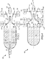
- an embodiment of a solid rocket motor 300 includes a combustion chamber 302, a single mass or “grain” of solid rocket motor propellant 304 in the chamber in a circular perforate or "CP" configuration, and a nozzle 306 coupled through a dome 308 to the chamber to expel the gas 310 produced by the burning propellant 304.
- Nozzle 306 includes a throat 312 that pinches down to a minimum cross-section to accelerate the velocity of the mass passing from the combustion chamber to the atmosphere.
- the nozzle may be configured with many shapes including but not limited to a convergent-divergent nozzle to provide choked flow.
- the cross-section of the CP may be circular or have a different pattern such as "fins" or a "star", which increase the surface area, hence rate of consumption.
- a first EOP system 320 is positioned at the head end of the SRM to inject gas 322 axially into combustion chamber 302. As shown, the EOP system 320 doubles as the thermal igniter to ignite SRM propellant 304. The EOP system 320 in an ignition condition is ignited and produces hot gas to ignite SRM propellant 304. The EOP system 320 may be turned off until supplemental mass, hence thrust is required. If an EOP system 320 is not so positioned, a conventional thermal igniter as shown in FIG. 1 may be required to ignite the SRM propellant 304.
- Second one or more EOP systems 330 are positioned to inject gas 332 just upstream of nozzle throat 312 to reduce the effective nozzle throat area At.
- Gas 322 is preferably injected from all sides around the nozzle, either discretely or contiguously. This can be accomplished with N EOP systems and N discrete injection apertures or with 1 to N EOP systems and a single contiguous injection aperture around the nozzle.
- a third plurality of EOP systems 340 is positioned to inject gas 342 at discrete locations downstream of nozzle throat 312 to implement thrust vector control (TVC).
- TVC thrust vector control
- any one or more of these systems can be implemented in a given SRM to manage thrust produced by the SRM propellant.
- different EOP systems may be configured to inject gas both just upstream of the nozzle throat 312 to provide a gross thrust adjustment and further upstream in the chamber itself to provide a fine adjustment.
- One or both of these systems to increase chamber pressure Pc may be used in combination with a system positioned downstream to provide TVC.
- an embodiment of a solid rocket motor 400 includes a combustion chamber 402, a single mass or “grain” of solid rocket motor propellant 404 in the chamber in an "end-burner” configuration, a thermal igniter 406 and a nozzle 408 coupled through a dome 409 to the chamber to expel gas 410 produced by burning propellant 404.
- the thermal igniter 406 may be mounted through the dome outside the motor as shown or may be a bag igniter inside the motor.
- Nozzle 408 includes a throat 412 that pinches down to a minimum cross-section to accelerate the velocity of the mass passing from the combustion chamber to the atmosphere.
- the "end-burner" configuration burns in an axial direction 414 along a longitudinal axis 416 of the motor.
- a first one or more EOP system 420 is positioned to inject gas 422 well upstream of the nozzle throat 412 to increase the mass in the combustion chamber.
- Gas 422 is preferably injected from all sides around the nozzle, either discretely or contiguously. This can be accomplished with N EOP systems and N discrete injection apertures or with 1 to N EOP systems and a single contiguous injection aperture around the nozzle.
- Second one or more EOP systems 430 are positioned to inject gas 432 just upstream of nozzle throat 412 to reduce the effective nozzle throat area At.
- Gas 322 is preferably injected from all sides around the nozzle, either discretely or contiguously. This can be accomplished with N EOP systems and N discrete injection apertures or with 1 to N EOP systems and a single contiguous injection aperture around the nozzle.
- a third plurality of EOP systems 440 is positioned to inject gas 442 at discrete locations downstream of nozzle throat 412 to implement thrust vector control (TVC).
- TVC thrust vector control
- EOP systems to inject gas into CP or end-burner unitary, hybrid or pulsed SRMs is no different.
- the most efficient configuration of the EOP systems for the different motor and different grain configurations may differ.
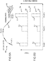
- an exemplary missile flight 500 for a missile 501 from an aircraft 502 is achieved with a chamber pressure Pc profile 503 and thrust profile 504 produced by burning SRM propellant as augmented with electrically operated propellant.
- burning the SRM propellant produces a constant MFR that generates a constant chamber pressure 506, which in turn produces a constant thrust 508.
- an EOP system is ignited to inject gas to provide an increased chamber pressure 510, hence increased thrust 512 to reach cruising speed. Missile flight continues for some period of time under SRM propellant thrust only.
- either the same EOP system or a different EOP system is ignited to inject gas to provide an increased chamber pressure 514, hence increased thrust 516 to gain speed and range. Missile flight continues for some period of time under SRM propellant thrust only.
- either the same EOP system or a different EOP system is ignited to inject gas to provide an increased chamber pressure 518, hence increased thrust 520 to execute a high-g maneuver to prosecute the target.
- the peak chamber pressure Pc must stay below a self-sustaining threshold pressure 522 of the electrically operated propellant in order to preserve the ability to extinguish the propellant by interrupting the electrical signal.
- the EOP system may, in general, be configured to produce either a choked or unchoked flow of gas to be injected into the chamber or downstream of the nozzle.
- the electrically operated propellant is burned in a separate mini combustion chamber and the gas is expelled through a nozzle into the main combustion chamber.
- the electrical ignition may comprise electrodes of varying configurations (e.g. parallel wires, parallel plates, angled plates, parallel or angled plates ( US 15/191,421 ) with an actuator to maintain positive contact of the electrically operated propellant with the plates ( US 15/247,194 ), etc.) or an EM source (Serial No 15/240,932 ).
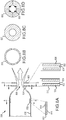
- an embodiment of an EOP system 600 for producing a choked flow of gas 601 comprises a combustion chamber 602, a pair of electrodes 604 and 606 and a mass of electrically operated propellant 608 positioned between the electrodes.
- the electrodes are coupled to an electrical power source 610 (e.g. a variable voltage source), which is controlled by a controller 612.
- An actuator 614 is positioned to apply a linear force 616 to the backside of the propellant to displace the propellant to maintain positive contact between the propellant and the electrodes.
- the actuator may, for example, comprise various springs, linear actuators, screw drives, rotating rods, gas pressure or hydraulic pistons to produce the requisite linear force or displacement.
- the pressurized gas may be diverted behind the propellant to assist the actuator.
- Electrodes 604 and 3606 are angled plate electrodes that extend into propellant 608 at an angle ⁇ roughly to an ignition surface 618 of the propellant at a minimum gap 620 between the electrodes.
- the minimum gap 620 is defined as the minimum gap between the electrodes that spans propellant.
- the angled contact surfaces 622 and 624 of the electrodes are symmetric about a plane 626 that extends into propellant 608.
- the energized electrodes produce current (field) lines 628 that follow equipotential surfaces 630 that are ideally curved and unevenly spaced.
- the curvature is determined by the angle ⁇ and the conductivity of the propellant. Typical values of ⁇ are 10 to 80 degrees (where 0 degrees is the flat plate configuration shown in Figures 2a-2d ).
- the spacing increases as the gap between the electrode increases and the concentration of field lines decreases. Irregularities or imperfections due, for example, to non-homogeneous propellant may induce small deviations in the curvature.
- the current (field) lines 628 are confined to the shallow volume where the electrodes are positioned and do not extend into the remaining bulk of the propellant 608.
- the equipotential surfaces 630 correspond to surfaces of uniform current density.
- the equipotential surface 630 at the minimum gap corresponds to the ignition surface 618 of uniform and maximum current density J that exceeds an ignition threshold of the propellant.
- the current density J decreases as the gap widens.
- an electrical input is applied across electrodes 604 and 606 to ignite and burn substantially the entire ignition surface 618 between the electrodes at the minimum gap to produce gases 632 that pressurize the combustion chamber. These gases may be released from the chamber through an opening 634 such as an orifice or nozzle to produce the choked flow of gas 632.
- Actuator 614 applies linear force 616 to displace the mass of propellant 608 towards the electrodes to maintain positive contact between the propellant at the ignition surface 618 and the electrode contact surfaces 622 and 624. As the burning consumes the propellant at the ignition surface, the linear force displaces new propellant forward to maintain the ignition surface 618 between the electrodes to continue burning.
- the displacement tends to overcome any irregularities or imperfections caused, for example, by non-homogeneities in the propellant itself to drive the contour of the ignition surface 618 to the curved contour of the equipotential surface at the minimum gap.
- This mechanism is what ensures that substantially the entire ignition surface ignites and combusts, as opposed to localized combustion on the surface or back burn. Combustion of the propellant produces gases that pressurize the combustion chamber.
- controller 612 In a throttling condition, controller 612 varies the electrical input to increase or decrease the rate of combustion to increase or decrease the pressure in the combustion chamber. In an extinguishment condition, provided the pressure in the chamber does not exceed the propellant's self-sustaining threshold pressure, the controller interrupts the electrical input to extinguish combustion.
- the propellant may be reignited by turning power back on to produce a maximum current density J that exceeds the ignition threshold.
- the electrically operated propellant is positioned and burned inside the main combustion chamber.
- a thin sheet of electrically operated propellant is disposed between a pair of electrodes at least one of which is a mesh electrode that provides a greater current density than the other electrode to initiate combustion of the electrically operated propellant at the mesh electrode.
- a thin-sheet EOP system 700 for producing an unchoked flow of gas 702 may have a circular shape to fit within a cylindrical casing (i.e. the combustion chamber). This circular shape is provided in the form of thin sheets of material. The thin sheets are of sufficient thickness to account for degradation of a surface of the respective EOP system when not ignited but still exposed to high heat in the casing. For example, combustion of the SRM propellant charge may cause high heat in the casing, which will not ignite the electrically operated propellant of the EOP system 700 when an electrical input is not applied. Nonetheless, a sacrificial portion, such as a thin portion, of the EOP system exposed to the high heat may degrade.
- Each EOP system 700 includes an electrically operated propellant 704 and corresponding electrodes 706 and 708.
- the electrically operated propellant 704 is configured (a) to ignite in response to an electrical input and (b) to generate gas when ignited.
- the electrically operated propellant 704 is configured to transition from an unignited state to an ignited state when a respective electrical input is applied between the respective pair of electrodes 706 and 708.
- the electrically operated propellant 704 is also configured to maintain the unignited state when the electrical input is not applied.
- the electrically operated propellant 704 is configured to transition from the ignited state to the unignited state when exposed to pressure less than a self-sustain threshold pressure, such as 200 psi, and the respective electrical input is not being applied.
- the electrodes 706 and 708 are mesh electrodes. Each electrode 706 and 708 covers a full opposing side of the electrically operated propellant 704, allowing electric current to move across the entirety of the electrically operated propellant 704.
- the depicted mesh is wire mesh having hole there through, such as being a circular or crisscrossed wire mesh.
- initial burning takes place only adjacent the first electrode 706 that is a coarse mesh electrode, while initial burning does not take place at the second electrode 708 that is a fine mesh electrode.
- the electrically operated propellant 704 is ignited, burning will take place adjacent both electrodes 706 and 708.
- current density J is the electric current per unit area of cross section.
- the basic thin-sheet EOP system 700 may be adapted to inject gas to the casing (combustion chamber) or downstream of the nozzle throat. In general, a hole is formed in the middle of the thin sheets to accommodate placement of the EOP system 700 either around the SRM propellant or around the nozzle.
- the thin sheet of electrically operated propellant and the electrodes are configured as an annular cylinder having radii R1 and R2 with R1 > R2 and an axial thickness t. In one configuration, the electrodes are placed on the front and back surfaces of a disk (thin axially, R1-R2> t) of electrically operated propellant.
- the disk configuration may, for example, be placed around the nozzle.
- the electrodes are placed on the inner and outer surfaces of a cylinder (thin radially R1-R2 ⁇ t) of electrically operated propellant.
- a cylinder thin radially R1-R2 ⁇ t
- electrically operated propellant can be formed around and along the SRM propellant. Consumption of the SRM propellant exposes the cylindrical sections, which can then be ignited to supplement the thrust produced by the SRM propellant.
- an embodiment of a SRM 800 is provided with thin-sheet EOP systems 802, 804 and 806 to inject gas upstream of a nozzle throat 808 to add mass, at the nozzle throat to reduce At and downstream of the nozzle thrust to provide TVC, respectively.
- the SRM propellant is not shown in order to emphasize the point that EOP injection can be used with any SRM motor and propellant configuration.
- Thin-sheet EOP system 802 comprises a cylinder 810 of electrically operated propellant 812 in which R1 - R2 ⁇ t1.
- Mesh electrodes 814 and 816 are placed on the inner and outer surfaces of propellant 812 inside a casing 818 (combustion chamber).
- the inner mesh electrode 814 is configured to provide a greater current density than the outer mesh electrode 816 to initiate combustion of the electrically operated propellant at the inner surface. Ignition of EOP system 802 produces gas that adds mass into the casing 818 upstream of the nozzle to increase chamber pressure Pc.
- the cylinder and electrodes may be contiguous or segmented.
- Thin-sheet EOP system 804 comprises a pair of disks 820 of electrically operated propellant 822 in which R3 - R4 > t2.
- Mesh electrodes 824 and 826 are placed on the front and back surfaces of propellant 822 for each disk.
- the front mesh electrode 824 is configured to provide a greater current density than the back mesh electrode 826 to initiate combustion of the electrically operated propellant at the inner surface.
- the dome or nozzle is configured such that the disk is operably coupled into the combustion chamber for unchoked gas flow. Ignition of EOP system 804 produces gas that is injected in to the combustion chamber at the nozzle throat to reduce At.
- the disks and electrodes may be contiguous or segmented.
- Thin-sheet EOP system 806 comprises a pair of disks 830 of electrically operated propellant 832 in which R3 - R4 > t2.
- Mesh electrodes 834 and 836 are placed on the front and back surfaces of propellant 832 for each disk.
- the front mesh electrode 834 is configured to provide a greater current density than the back mesh electrode 836 to initiate combustion of the electrically operated propellant at the inner surface.
- the disks and electrodes are segmented and configured to inject gas through discrete openings 838 into the exhaust to perform TVC.
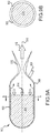
- an embodiment of a unitary end-burner SRM 900 includes a plurality cylindrical thin-sheet EOP systems 902 formed around and along the length of a cylindrical SRM propellant 904 inside a casing 906 (combustion chamber).
- An end-burner thermal igniter 908 mounted inside or outside of the motor is configured to ignite SRM propellant 904, which in turn produces gas to pressurize the combustion chamber.
- the high-pressure gas 910 flows through nozzle 912 to produce thrust.
- each EOP system 902 is independently controllable to be used as a 1-shot device to generate a maximum impulse or as a controlled device to be turned on and off and throttled as required by the mission. Multiple EOP systems 904 could be used in combination to provide greater thrust capability.
- This configuration of cylindrical thin-sheet EOP systems has no impact on the motor casing and minimal impact on the mass of SRM propellant in the motor.
- an embodiment of a hybrid SRM 1000 includes a forward segment of SRM propellant 1002 configured as an end-burner and an aft segment of SRM propellant 1004 configured as a fin variant of a CP grain.
- a plurality of cylindrical thin-sheet EOP systems 1006 is formed around and along the length of both the aft and forward segments of SRM propellant 1002 and 1004 inside a casing 1008 (combustion chamber).
- An end-burner thermal igniter 1010 mounted inside or outside of the motor is configured to ignite both the aft and forward segments of SRM propellant 1002 and 1004 at essentially the same time to produce high pressure gas 1012 that flows through a nozzle 1014 to produce thrust.
- the end-burner propellant 1004 bums for a relatively long time e.g. the entire engagement, to produce a steady-state thrust.
- the fin CP grain 1006 is consumed relatively rapidly to rapidly accelerate the missile during fly-out. Once the fin CP grain 1006 is fully consumed, the furthest aft EOP system 1006 is exposed and capable of being ignited to provide additional mass to increase Pc and provide additional thrust. As the end-burner propellant 1004 is consumed, additional EOP systems 1006 are exposed and capable of being ignited to provide additional mass to increase Pc and provide additional thrust.
- an embodiment of a hybrid SRM 1100 includes a forward segment of SRM propellant 1102 configured as CP grain and an aft segment of SRM propellant 1104 configured as a fin variant of a CP grain that is consumed faster than the CP grain.
- a plurality of cylindrical thin-sheet EOP systems 1106 is formed around and along the length of only the aft segment of SRM propellant 1104 inside a casing 1108 (combustion chamber).
- a thermal igniter 1110 mounted inside or outside of the motor is configured to ignite both the aft and forward segments of SRM propellant 1102 and 1104 at essentially the same time to produce high-pressure gas 1112 that flows through a nozzle 1114 to produce thrust.
- the CP grain 1104 burns for a relatively long time e.g. the entire engagement, to produce a steady-state thrust.
- the fin CP grain 1106 is consumed relatively rapidly to rapidly accelerate the missile during fly-out. Once the fin CP grain 1106 is fully consumed, the EOP systems 1106 are exposed and capable of being ignited to provide additional mass to increase Pc and provide additional thrust.
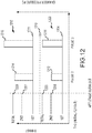
- an exemplary missile flight is achieved with a chamber pressure Pc profile 1200 and thrust profile 1202 produced by burning forward and aft sections of SRM propellant as augmented with electrically operated propellant such as depicted in FIGs. 10a-10c and 11a-11c .
- both the forward and aft sections are ignited and burn.
- the forward section produces an amount of gas (mass) that generates a steady-state chamber pressure Pc 1204 and thrust 1211 whereas the aft section is consumed faster and produces a larger amount of gas (mass) that generates a transient chamber pressure Pc 1206 and thrust 1207 which sum together during initial fly-out to produce a total Pc 1208 and thrust 1209 to accelerate the missile to speed.
- the total PC 1208 must be less than the self-sustaining threshold pressure 1210 of the electrically operated propellant in order to retain the capability to extinguish the electrically operated propellant once ignited, and to reignite the propellant.
- the aft section has been consumed and only the forward section produces mass to pressure the chamber and produce the steady-state Pc 1204 and thrust 1211.
- Consumption of the aft section has exposed one or more of the EOP systems, which can now be selectively controlled to inject gas into the chamber to, for example, increased chamber pressure 1212, hence increased thrust 1214 to gain speed and range and to inject gas to provide an increased chamber pressure 1216, hence increased thrust 1218 to execute a high-g maneuver to prosecute the target.
- the peak chamber pressure Pc must stay below a self-sustaining threshold pressure 1210 of the electrically operated propellant in order to preserve the ability to extinguish the propellant by interrupting the electrical signal.
- an embodiment of a pulsed SRM 1300 includes a plurality of cylindrical thin-sheet EOP systems 1302 to provide supplemental thrust.
- Other configurations of the EOP system may be used to add mass, reduce At or provide TVC for the pulsed SRM.
- Embodiments of the pulsed SRM are disclosed in U.S. 14/875,741 entitled “Electrically Operated Pulse Initiators and Ignition” filed October 6, 2015.
- the pulsed motor uses electrically operated propellant initiators 1304, which are similar in construct and operation to the EOP systems but serve a different function.
- the initiators 1304 are used to both isolate segments of SRM propellant 1306 so that the segments can be individually initiated and to initiate combustion of at least some of the segments 1306 of SRM propellant.
- the aft segment 1306 is typically ignited with an end-burner igniter 1308.
- the initiator includes a thin sheet of electrically operated propellant disposed between a pair of mesh electrodes (the less dense mesh electrode facing forward to initiate burn adjacent the next segment).
- the sheet of electrically operated propellant serves as a barrier to isolate one segment of SRM propellant from the hot gases produced by another burning propellant.
- the initiator applies an electrical signal in an ignition condition to the thin sheet to ignite the electrically operated propellant, which in turn produces hot gasses that ignite the corresponding segment of SRM propellant.
- the consumption of each segment 1306 exposes one or more of the EOP systems 1302 so that they may be ignited to produce additional mass.
- each segment 1306 produces gas (mass) sufficient to pressure the combustion chamber to a chamber pressure 1310 to expel gas through a nozzle 1312 to produce a thrust pulse 1314.
- the level and duration of Pc/thrust depends on the grain configuration of each segment 1306.
- the timing of each pulse is controlled by its initiator.
- Each pulse may be augmented by igniting one or more of the EOP systems to produce a 1-shot impulse or a controlled pulse of pressure 1316 and thrust 1318.
- the combination of the pulsed motor with EOP thrust management provides a SRM with considerable capabilities to prosecute targets. While several illustrative embodiments of the invention have been shown and described, numerous variations and alternate embodiments will occur to those skilled in the art. Such variations and alternate embodiments are contemplated, and can be made without departing from the scope of the invention as defined in the appended claims.
Landscapes
- Engineering & Computer Science (AREA)
- Chemical & Material Sciences (AREA)
- Combustion & Propulsion (AREA)
- Mechanical Engineering (AREA)
- General Engineering & Computer Science (AREA)
- Remote Sensing (AREA)
- Aviation & Aerospace Engineering (AREA)
- Testing Of Engines (AREA)
Claims (15)
- Feststoffraketenmotor (300), umfassend:eine Verbrennungskammer (302);eine Düse (306), die an die Verbrennungskammer gekoppelt ist, wobei die Düse eine Engstelle (312) mit einer effektiven Engstellenfläche At aufweist;ein oder mehrere Segmente (304) mit Feststoffraketenmotor (SRM)-Treibmittel innerhalb der Verbrennungskammer;eine thermische Zündung, die an mindestens eines von dem einen oder den mehreren Segmenten des SRM-Treibmittels gekoppelt ist, wobei jedes Segment des SRM-Treibmittels, nachdem es gezündet wurde, vollständig verbrennt, um Druckgas in der Verbrennungskammer mit einem Kammerdruck Pc zu produzieren, welches durch die Engstelle der Düse strömt, um Schub zu produzieren;ein elektrisch betriebenes Treibmittel (320); undeine elektrische Zündung, die konfiguriert ist, um eine elektrische Eingabe an das elektrisch betriebene Treibmittel anzulegen, wobei das elektrisch betriebene Treibmittel in einem Zündzustand verbrennt, um Gas zu produzieren, um (a) der Kammer vorgeordnet zu der Düsenengstelle Masse hinzuzufügen, um den Kammerdruck Pc zu erhöhen, (b) die effektive Engstellenfläche At zu reduzieren, um den Kammerdruck Pc zu erhöhen, oder (c) Masse nachgeordnet zu der Düsenengstelle zu injizieren, um Schubvektorsteuerung (TVC) bereitzustellen, oder eine Kombination davon,dadurch gekennzeichnet, dassdas elektrisch betriebene Treibmittel einen selbsttragenden Schwellendruck aufweist, bei dem das Treibmittel, nachdem es gezündet wurde, nicht gelöscht werden kann, und unter dem das Treibmittel durch Unterbrechung des elektrischen Signals gelöscht werden kann, wobei die elektrische Zündung konfiguriert ist, um in einem Löschzustand die elektrische Eingabe zu unterbrechen, um das elektrisch betriebene Treibmittel zu löschen, wobei die elektrische Zündung in dem Zündzustand umkonfiguriert wird, um die elektrische Eingabe anzulegen, um das elektrisch betriebene Treibmittel erneut zu zünden.
- Feststoffraketenmotor nach Anspruch 1, wobei der selbsttragende Schwellendruck mindestens 500 psi (3,45 MPa) beträgt.
- Feststoffraketenmotor nach Anspruch 1, wobei die elektrische Zündung ein Paar von Elektroden umfasst und das elektrisch betriebene Treibmittel als dünne Lage konfiguriert ist, die zwischen dem Paar von Elektroden angeordnet ist, wobei mindestens eine von dem Paar von Elektroden eine Maschenelektrode ist, die eine größere Stromdichte als die andere Elektrode bereitstellt, um die Verbrennung des elektrisch betriebenen Treibmittels an der Maschenelektrode zu initiieren,
wobei gegebenenfalls die dünne Lage des elektrisch betriebenen Treibmittels als kranzförmiger Zylinder mit den Radien R1 und R2, wobei R1 > R2 ist, der axialen Dicke t, und R1 - R2 > t konfiguriert ist, wobei das Paar von Elektroden auf den vorderen und rückseitigen Oberflächen des kranzförmigen Zylinders des elektrisch betriebenen Treibmittels angeordnet ist, um die Verbrennung an der exponierten vorderen Oberfläche zu initiieren, und wobei des Weiteren gegebenenfalls die dünne Lage des elektrisch betriebenen Treibmittels als kranzförmiger Zylinder mit den Radien R1 und R2, wobei R1 > R2 ist, der axialen Dicke t, und R1 - R2 < t konfiguriert ist, wobei das Paar der Elektroden auf inneren und äußeren Oberflächen des kranzförmigen Zylinders des elektrisch betriebenen Treibmittels angeordnet ist, um die Verbrennung auf der exponierten inneren Oberfläche zu initiieren. - Feststoffraketenmotor nach Anspruch 3, wobei die elektrische Zündung in dem Zündzustand konfiguriert ist, um die elektrische Eingabe so anzulegen, dass alles von der dünnen Lage des elektrisch betriebenen Treibmittels verbraucht wird, um einen Impulsschubzustand oder einen Impuls-TVC-Zustand zu erzeugen.
- Feststoffraketenmotor nach Anspruch 1, wobei eine Gesamtmasse des elektrisch betriebenen Treibmittels geringer als 5 % einer Gesamtmasse des SRM-Treibmittels ist, wobei ein maximaler zusätzlicher Sofortschub geringer als 25 % eines Schubs im stationären Zustand ist, der durch Verbrennen des SRM-Treibmittels bereitgestellt wird.
- Feststoffraketenmotor nach Anspruch 1, wobei der Motor nur ein einzelnes Segment des SRM-Treibmittels einschließt.
- Feststoffraketenmotor nach Anspruch 1, wobei der Motor nur ein einzelnes Segment des SRM-Treibmittels einschließt, und wobei das einzelne Segment des SRM-Treibmittels als Endbrenner konfiguriert ist, wobei das elektrisch betriebene Treibmittel eine Vielzahl von zylindrischen Abschnitten von elektrisch betriebenem Treibmittel umfasst, die um das einzelne Segment des SRM-Treibmittels herum und an diesem entlang positioniert sind, wobei die elektrische Zündung eine gleiche Anzahl von Elektrodenpaaren auf gegenüber liegenden inneren und äußeren Oberflächen der zylindrischen Abschnitte von elektrisch betriebenem Treibmittel umfasst, von denen mindestens eine von jedem derartigen Paar eine Maschenelektrode ist, die eine größere Stromdichte als die andere Elektrode bereitstellt, um die Verbrennung des elektrisch betriebenen Treibmittels an der inneren Oberfläche des elektrisch betriebenen Treibmittels zu initiieren, wobei die thermische Zündung konfiguriert ist, um eine heckwärtige Oberfläche des einzelnen Segments des SRM-Treibmittels so zu zünden, dass sie brennt, und sich axial in einer vorwärtigen Richtung zurückzieht, um die inneren Oberflächen der zylindrischen Abschnitte des elektrischen Treibmittels nacheinander zu exponieren, wobei in dem Maße, in dem jeder zylindrische Abschnitt exponiert wird, das Anlegen des elektrischen Signals in dem Zündzustand jenen zylindrische Abschnitt zündet, um Gas zu produzieren, um der Kammer Masse zuzufügen.
- Feststoffraketenmotor nach Anspruch 1, wobei der Motor mindestens ein erstes Segment von SRM-Treibmittel mit einem ersten Korndesign und ein zweites Segment von SRM-Treibmittel umfasst, das heckwärts zu dem ersten Segment positioniert ist und ein zweites Korndesign aufweist, das so konfiguriert ist, dass es sich schneller verbraucht als das erste Korndesign, wobei das elektrisch betriebene Treibmittel mindestens einen zylindrischen Abschnitt des elektrisch betriebenen Treibmittels umfasst, der um das zweite Segment des SRM-Treibmittels herum und an diesem entlang positioniert ist, wobei die elektrische Zündung mindestens ein Elektrodenpaar auf gegenüber liegenden inneren und äußeren Oberflächen des mindestens einen zylindrischen Abschnitts des elektrisch betriebenen Treibmittels umfasst, bei denen mindestens eine von jedem Paar eine Maschenelektrode ist, die eine größere Stromdichte als die andere Elektrode bereitstellt, um die Verbrennung des elektrisch betriebenen Treibmittels an der inneren Oberfläche des elektrisch betriebenen Treibmittels zu initiieren, wobei die thermische Zündung konfiguriert ist, um das zweite Segment des SRM-Brennstoffs zu zünden, so dass es brennt und sich radial zurückzieht, um die innere Oberfläche des mindestens einen zylindrischen Abschnitts des elektrisch betriebenen Treibmittels zu exponieren, wobei in dem Maße, in dem jeder von dem mindestens einen zylindrischen Abschnitt exponiert wird, das Anlegen des elektrischen Signals in dem Zündzustand jenen zylindrischen Abschnitt zündet, um Gas zu produzieren, um der Kammer Masse hinzuzufügen, um die Verbrennung des ersten Segments des SRM-Treibmittels zu steigern.
- Feststoffraketenmotor nach Anspruch 8, wobei das erste Segment als Endbrenner konfiguriert ist, wobei das elektrisch betriebene Treibmittel eine Vielzahl zylindrischer Abschnitte von elektrisch betriebenem Treibmittel und Elektrodenpaaren umfasst, die um sowohl die ersten als auch die zweiten Segmente des SRM-Treibmittels herum und entlang diesen positioniert sind.
- Feststoffraketenmotor nach Anspruch 1, wobei der Motor mindestens erste und zweite Segmente des SRM-Treibmittels, mindestens einen ersten elektrisch betriebenen Treibmittelinitiator umfasst, der funktional an mindestens das zweite Segment des SRM-Treibmittels gekoppelt ist, um die Verbrennung in mindestens dem zweiten Segment des SRM-Treibmittels zu initiieren, wobei die mindestens ersten und zweiten Segmente des SRM-Treibmittels funktional voneinander isoliert sind, so dass mindestens die ersten und zweiten Segmente des SRM-Treibmittels individuell initiiert werden können, wobei gegebenenfalls mindestens die ersten und zweiten Segmente des SRM-Treibmittels als Endbrenner konfiguriert sind, wobei mindestens der erste elektrisch betriebene Treibmittelinitiator zwischen den ersten und zweiten Segmenten des SRM-Treibmittels positioniert ist, um die Segmente des SRM-Treibmittels zu isolieren, und wobei des Weiteren gegebenenfalls das elektrisch betriebene Treibmittel mindestens einen zylindrischen Abschnitt des elektrisch betriebenen Treibmittels umfasst, der um das erste Segment des SRM-Treibmittels herum und entlang diesem positioniert ist, wobei die elektrische Zündung mindestens ein Elektrodenpaar auf gegenüber liegenden inneren und äußeren Oberflächen des mindestens einen zylindrischen Abschnitts des elektrisch betriebenen Treibmittels umfasst, wobei mindestens eine von jedem derartigen Paar eine Maschenelektrode ist, die eine größere Stromdichte als die andere Elektrode bereitstellt, um die Verbrennung des elektrisch betriebenen Treibmittels an der inneren Oberfläche des elektrisch betriebenen Treibmittels zu initiieren, wobei die thermische Zündung konfiguriert ist, um das erste Segment des SRM-Treibmittels zu zünden, um dies an dem ersten elektrisch betriebenen Treibmittelinitiator zu verbrennen und axial zurückzuziehen, bis es verbraucht ist, um die innere Oberfläche des mindestens einen zylindrischen Abschnitts des elektrisch betriebenen Treibmittels zu exponieren, wobei in dem Maße, in dem jeder zylindrische Abschnitt exponiert wird, Anlegen des elektrischen Signals in dem Zündzustand jenen zylindrischen Abschnitt zündet, um Gas zu produzieren, um der Kammer Masse hinzuzufügen.
- Feststoffraketenmotor nach Anspruch 1, wobei das elektrisch betriebene Treibmittel und die elektrische Zündung konfiguriert sind, um sowohl und selektiv die effektive Fläche At der Engstelle zu reduzieren, um eine grobe Schubanpassung bereitzustellen als auch vorgeordnet zu der Engstelle Masse hinzuzufügen, um eine feine Schubanpassung bereitzustellen.
- Feststoffraketenmotor nach Anspruch 1,
wobei das elektrisch betriebene Treibmittel eine Vielzahl zylindrischer Abschnitte aus elektrisch betriebenem Treibmittel umfasst, die um das eine oder die mehreren Segmente des SRM-Treibmittels herum und entlang diesen positioniert sind; und die elektrische Zündung eine Vielzahl von Elektrodenpaaren auf gegenüber liegenden inneren und äußeren Oberflächen von der Vielzahl der zylindrischen Abschnitte des elektrisch betriebenen Treibmittels umfasst, von denen mindestens eine von jedem derartigen Paar eine Maschenelektrode ist, die eine größere Stromdichte als die andere Elektrode bereitstellt, um Verbrennung des elektrisch betriebenen Treibmittels an der inneren Oberfläche des elektrisch betriebenen Treibmittels zu initiieren, wobei in dem Maße, in dem jeder zylindrische Abschnitt des elektrisch betriebenen Treibmittels exponiert wird, indem das eine oder die mehreren Segmente des SRM-Treibmittels verbraucht wird bzw. werden, Anlegen des elektrischen Signals in dem Zündzustand jenen zylindrischen Abschnitt zündet, um Gas zu produzieren, um der Kammer Masse hinzuzufügen, um die Verbrennung des SRM-Treibmittels zu steigern und den Kammerdruck Pc zu erhöhen. - Verfahren zur Verwaltung von Schub aus einem Feststoffraketenmotor (300) (SRM), wobei der SRM eine Düse (306), die an eine Verbrennungskammer (302) gekoppelt ist, wobei die Düse eine Engstelle (312) mit einer effektiven Engstellenfläche, At, aufweist, ein oder mehrere Segmente von Feststoffraketenmotor (SRM)-Treibmittel innerhalb der Verbrennungskammer und eine thermische Zündung einschließt, die an mindestens eines des einen oder der mehreren Segmente des SRM-Treibmittels gekoppelt ist, wobei jedes Segment des SRM-Treibmittels, nachdem es gezündet wurde, vollständig verbrennt, um Druckgas in der Verbrennungskammer mit einem Druck Pc zu produzieren, das durch die Engstelle der Düse hindurch strömt, um Schub zu produzieren, wobei das Verfahren umfasst:Anlegen einer elektrischen Eingabe an ein elektrisch betriebenes Treibmittel, wobei das elektrisch betriebene Treibmittel in einem Zündzustand verbrennt, um Gas zu produzieren, um (a) der Kammer vorgeordnet zu der Düsenengstelle Masse hinzuzufügen, um den Kammerdruck Pc zu erhöhen, (b) die effektive Engstellenfläche At zu reduzieren, um den Kammerdruck Pc zu erhöhen, oder (c) Masse nachgeordnet zu der Düsenengstelle zu injizieren, um Schubvektorsteuerung bereitzustellen, oder eine Kombination davon, und dadurch gekennzeichnet, dassdas elektrisch betriebene Treibmittel einen selbsttragenden Schwellendruck aufweist, bei dem das Treibmittel, nachdem es entzündet wurde, nicht gelöscht werden kann, und unterhalb dessen das Treibmittel durch Unterbrechung des elektrischen Signals gelöscht werden kann, des Weiteren umfassend:im Löschzustand Unterbrechen der elektrischen Eingabe, um das elektrisch betriebene Treibmittel zu löschen; undim Zündzustand erneutes Anlegen der elektrischen Eingabe, um das elektrisch betriebene Treibmittel erneut zu zünden.
- Verfahren nach Anspruch 13, wobei das elektrisch betriebene Treibmittel eine Vielzahl von zylindrischen Abschnitten von elektrisch betriebenem Treibmittel umfasst, die um das eine oder die mehreren Segmente von SRM-Treibmittel herum und an diesen entlang positioniert sind, wobei in dem Maße, in dem das eine oder die mehreren Segmente des SRM-Treibmittels verbraucht werden, die Vielzahl der zylindrischen Abschnitte des elektrisch betriebenen Treibmittels der Reihe nach exponiert werden, wobei das Verfahren des Weiteren Anlegen des elektrischen Signals an den exponierten zylindrischen Abschnitt in dem Zündzustand umfasst, um jenen zylindrischen Abschnitt an elektrisch betriebenem Treibmittel zu verbrennen, um der Kammer vorgeordnet zu der Düsenengstelle Masse hinzuzufügen.
- Verfahren nach Anspruch 13, wobei der Motor mindestens erste und zweite Segmente an SRM-Treibmittel, mindestens einen ersten elektrisch betriebenen Treibmittelinitiator umfasst, der funktional an mindestens das zweite Segment des SRM-Treibmittels gekoppelt ist, um die Verbrennung in mindestens dem zweiten Segment des SRM-Treibmittels zu initiieren, wobei die mindestens ersten und zweiten Segmente des SRM-Treibmittels funktional voneinander isoliert sind, so dass mindestens die ersten und zweiten Segmente des SRM-Treibmittels individuell initiiert werden können.
Applications Claiming Priority (2)
| Application Number | Priority Date | Filing Date | Title |
|---|---|---|---|
| US15/274,669 US10563617B2 (en) | 2016-09-23 | 2016-09-23 | Electrically operated propellant for solid rocket motor thrust management |
| PCT/US2017/052207 WO2018125327A1 (en) | 2016-09-23 | 2017-09-19 | Electrically operated propellant for solid rocket motor thrust management |
Publications (2)
| Publication Number | Publication Date |
|---|---|
| EP3516196A1 EP3516196A1 (de) | 2019-07-31 |
| EP3516196B1 true EP3516196B1 (de) | 2020-06-17 |
Family
ID=61913517
Family Applications (1)
| Application Number | Title | Priority Date | Filing Date |
|---|---|---|---|
| EP17861183.6A Active EP3516196B1 (de) | 2016-09-23 | 2017-09-19 | Elektrisch betriebenes treibmittel zur schubverwaltung bei einem feststoffraketenmotor |
Country Status (4)
| Country | Link |
|---|---|
| US (1) | US10563617B2 (de) |
| EP (1) | EP3516196B1 (de) |
| AU (1) | AU2017387526B2 (de) |
| WO (1) | WO2018125327A1 (de) |
Families Citing this family (18)
| Publication number | Priority date | Publication date | Assignee | Title |
|---|---|---|---|---|
| US10598128B1 (en) | 2014-09-05 | 2020-03-24 | Valley Tech Systems, Inc. | Attitude control system |
| US9927217B1 (en) | 2014-09-05 | 2018-03-27 | Valley Tech Systems, Inc. | Attitude control system |
| US11143143B1 (en) | 2018-05-11 | 2021-10-12 | Valley Tech Systems, Inc. | Extinguishable divert system |
| US12060853B2 (en) | 2019-01-30 | 2024-08-13 | Laboratoire Reaction Dynamics Inc. | Rocket engine with integrated oxidizer catalyst in manifold and injector assembly |
| WO2020154809A1 (en) | 2019-01-30 | 2020-08-06 | Laboratoire Reaction Dynamics Inc. | Rocket engines |
| CN109958548A (zh) * | 2019-03-12 | 2019-07-02 | 湖北航天化学技术研究所 | 一种快速发射用固体火箭发动机模块化装药工艺 |
| CN110469426B (zh) * | 2019-08-22 | 2020-07-31 | 中国人民解放军国防科技大学 | 一种推力连续可调的固体火箭发动机及固体火箭 |
| US12522381B2 (en) * | 2020-07-31 | 2026-01-13 | Utah State University Space Dynamics Laboratory | Miniaturized green end-burning hybrid propulsion system for cubesats |
| CN112177797B (zh) * | 2020-09-16 | 2021-11-05 | 西北工业大学 | 一种无喷管固体火箭发动机 |
| US11512668B2 (en) * | 2020-11-28 | 2022-11-29 | Raytheon Company | Multi-pulse solid rocket motor ignition method |
| CN112392629B (zh) * | 2021-01-04 | 2021-04-09 | 北京航空航天大学 | 固液-固体共燃烧室组合动力火箭发动机及飞行器 |
| CN113217228B (zh) * | 2021-06-18 | 2022-04-08 | 西北工业大学 | 一种用于固体火箭发动机的磁控式推力矢量控制装置 |
| US12060852B2 (en) * | 2021-11-12 | 2024-08-13 | The Aerospace Corporation | Electrochemical rocket motor |
| CN114810418A (zh) * | 2022-04-28 | 2022-07-29 | 西安近代化学研究所 | 一种基于气压驱动的药柱供给装置及电控固体发动机 |
| CN116478003B (zh) * | 2022-07-11 | 2025-09-16 | 中国船舶重工集团公司第七一三研究所 | 电控固体推进剂动力装置、药柱燃面与电极的接触方法 |
| CN115839291B (zh) * | 2022-09-29 | 2025-06-03 | 上海新力动力设备研究所 | 一种固体火箭发动机塞式矢量喷管结构 |
| CN116592395B (zh) * | 2023-05-17 | 2025-11-18 | 西北工业大学 | 一种变结构rbcc燃烧室及其燃烧组织方法 |
| CN119429188B (zh) * | 2024-12-20 | 2025-10-17 | 湖北三江航天红林探控有限公司 | 一种导气式自驱动动力装置 |
Family Cites Families (18)
| Publication number | Priority date | Publication date | Assignee | Title |
|---|---|---|---|---|
| US3031842A (en) | 1959-05-18 | 1962-05-01 | United Aircraft Corp | Thrust control for solid rocket |
| US3167912A (en) | 1960-01-04 | 1965-02-02 | United Aircraft Corp | Thrust control for solid rocket |
| US3293855A (en) * | 1963-10-16 | 1966-12-27 | Gen Motors Corp | Reignitable rocket |
| US3426972A (en) | 1966-08-16 | 1969-02-11 | Thiokol Chemical Corp | Rocket motor thrust vector control apparatus |
| US3563467A (en) | 1966-09-07 | 1971-02-16 | Thiokol Chemical Corp | Rocket motor thrust nozzles |
| US3759039A (en) * | 1968-11-22 | 1973-09-18 | Thiokol Chemical Corp | Thrust control and modulation system |
| US4552926A (en) | 1983-09-26 | 1985-11-12 | Ciba-Geigy Corporation | Substituted 4-hydroxyphenylthio benzoate stabilizers |
| US4840024A (en) | 1984-08-20 | 1989-06-20 | Morton Thiokol, Inc. | Multiple propellant solid rocket motor |
| US7788900B2 (en) * | 2002-01-16 | 2010-09-07 | Michael Dulligan | Electrically controlled extinguishable solid propellant motors |
| US6982013B1 (en) * | 2003-03-17 | 2006-01-03 | The United States Of America As Represented By The Secretary Of The Navy | Electrostatic charge dissipation compositions including energetic particles |
| US7281367B2 (en) * | 2003-12-05 | 2007-10-16 | Alliant Techsystems Inc. | Steerable, intermittently operable rocket propulsion system |
| US7464535B2 (en) | 2004-06-29 | 2008-12-16 | Honeywell International Inc. | Rocket motor nozzle throat area control system and method |
| US7716912B2 (en) | 2006-03-02 | 2010-05-18 | Alliant Techsystems Inc. | Propulsion thrust control system and method |
| US7685940B1 (en) * | 2008-03-21 | 2010-03-30 | Raytheon Company | Rocket motor with pellet and bulk solid propellants |
| US8857338B2 (en) * | 2008-05-16 | 2014-10-14 | Digital Solid State Propulsion Llc | Electrode ignition and control of electrically ignitable materials |
| US8584443B1 (en) | 2008-09-16 | 2013-11-19 | Digital Solid State Propulsion, Llc | Method and system for controlling solid propellant thrust |
| US20130097995A1 (en) * | 2011-10-25 | 2013-04-25 | General Dynamics Ordnance And Tactical Systems, Inc. | System and method for controlling an object traveling through exoatmospheric space |
| US8950329B2 (en) | 2012-12-24 | 2015-02-10 | Raytheon Company | Electrically operated propellants |
-
2016
- 2016-09-23 US US15/274,669 patent/US10563617B2/en active Active
-
2017
- 2017-09-19 WO PCT/US2017/052207 patent/WO2018125327A1/en not_active Ceased
- 2017-09-19 AU AU2017387526A patent/AU2017387526B2/en active Active
- 2017-09-19 EP EP17861183.6A patent/EP3516196B1/de active Active
Non-Patent Citations (1)
| Title |
|---|
| None * |
Also Published As
| Publication number | Publication date |
|---|---|
| WO2018125327A1 (en) | 2018-07-05 |
| AU2017387526A1 (en) | 2019-01-24 |
| AU2017387526B2 (en) | 2021-09-23 |
| US10563617B2 (en) | 2020-02-18 |
| EP3516196A1 (de) | 2019-07-31 |
| CA3031789A1 (en) | 2018-07-05 |
| US20180128207A1 (en) | 2018-05-10 |
Similar Documents
| Publication | Publication Date | Title |
|---|---|---|
| EP3516196B1 (de) | Elektrisch betriebenes treibmittel zur schubverwaltung bei einem feststoffraketenmotor | |
| US7281367B2 (en) | Steerable, intermittently operable rocket propulsion system | |
| US4741154A (en) | Rotary detonation engine | |
| US4722261A (en) | Extendable ram cannon | |
| US8584443B1 (en) | Method and system for controlling solid propellant thrust | |
| JP6082575B2 (ja) | パルスデトネーション燃焼器の作動中にデトネーション移行を位置付ける方法 | |
| US5394690A (en) | Constant pressure, variable thrust bipropellant engine | |
| US20200393128A1 (en) | Variable geometry rotating detonation combustor | |
| US3844118A (en) | Aft inlet ramjet powered missile | |
| EP2297543B1 (de) | Festbrennstoff-pt-cas (pellet thrust and control actuation system) zum manövrieren eines flugkörpers | |
| WO2000040919B1 (en) | Improved propulsion system | |
| US20090211225A1 (en) | Systems and methods for varying the thrust of rocket motors and engines while maintaining higher efficiency using moveable plug nozzles | |
| US5152136A (en) | Solid fuel ducted rocket with gel-oxidizer augmentation propulsion | |
| EP3850206B1 (de) | Mittels harzinjektionsverfahren geformte raketenmotordüse mit adaptiver geometrie | |
| DE112012005264T5 (de) | Rotations-Pulsdetonationstriebwerk | |
| US9726115B1 (en) | Selectable ramjet propulsion system | |
| CA3031789C (en) | Electrically operated propellant for solid rocket motor thrust management | |
| Sayles | Development of test motors for advanced controllable propellants | |
| JPH0534510B2 (de) | ||
| US20040206089A1 (en) | Integral pulse detonation system for a gas turbine engine | |
| US4338783A (en) | Two-stage hypersonic ramjet | |
| EP4251871B1 (de) | Mehrpuls-festbrennstoffraketenmotor und zündungsverfahren | |
| EP4211344B1 (de) | Feststoffraketenmotorzündverfahren mit variabler brenngeschwindigkeit | |
| US3626697A (en) | Method and means for controlling the thrust in a solid propellant rocket motor | |
| Hardgrove et al. | High performance throttling and pulsing rocket engine |
Legal Events
| Date | Code | Title | Description |
|---|---|---|---|
| STAA | Information on the status of an ep patent application or granted ep patent |
Free format text: STATUS: UNKNOWN |
|
| STAA | Information on the status of an ep patent application or granted ep patent |
Free format text: STATUS: THE INTERNATIONAL PUBLICATION HAS BEEN MADE |
|
| PUAI | Public reference made under article 153(3) epc to a published international application that has entered the european phase |
Free format text: ORIGINAL CODE: 0009012 |
|
| STAA | Information on the status of an ep patent application or granted ep patent |
Free format text: STATUS: REQUEST FOR EXAMINATION WAS MADE |
|
| 17P | Request for examination filed |
Effective date: 20190129 |
|
| AK | Designated contracting states |
Kind code of ref document: A1 Designated state(s): AL AT BE BG CH CY CZ DE DK EE ES FI FR GB GR HR HU IE IS IT LI LT LU LV MC MK MT NL NO PL PT RO RS SE SI SK SM TR |
|
| AX | Request for extension of the european patent |
Extension state: BA ME |
|
| DAV | Request for validation of the european patent (deleted) | ||
| DAX | Request for extension of the european patent (deleted) | ||
| GRAP | Despatch of communication of intention to grant a patent |
Free format text: ORIGINAL CODE: EPIDOSNIGR1 |
|
| STAA | Information on the status of an ep patent application or granted ep patent |
Free format text: STATUS: GRANT OF PATENT IS INTENDED |
|
| INTG | Intention to grant announced |
Effective date: 20200323 |
|
| GRAS | Grant fee paid |
Free format text: ORIGINAL CODE: EPIDOSNIGR3 |
|
| GRAA | (expected) grant |
Free format text: ORIGINAL CODE: 0009210 |
|
| STAA | Information on the status of an ep patent application or granted ep patent |
Free format text: STATUS: THE PATENT HAS BEEN GRANTED |
|
| AK | Designated contracting states |
Kind code of ref document: B1 Designated state(s): AL AT BE BG CH CY CZ DE DK EE ES FI FR GB GR HR HU IE IS IT LI LT LU LV MC MK MT NL NO PL PT RO RS SE SI SK SM TR |
|
| REG | Reference to a national code |
Ref country code: GB Ref legal event code: FG4D |
|
| REG | Reference to a national code |
Ref country code: CH Ref legal event code: EP |
|
| REG | Reference to a national code |
Ref country code: DE Ref legal event code: R096 Ref document number: 602017018504 Country of ref document: DE |
|
| REG | Reference to a national code |
Ref country code: IE Ref legal event code: FG4D |
|
| REG | Reference to a national code |
Ref country code: AT Ref legal event code: REF Ref document number: 1281594 Country of ref document: AT Kind code of ref document: T Effective date: 20200715 |
|
| PG25 | Lapsed in a contracting state [announced via postgrant information from national office to epo] |
Ref country code: SE Free format text: LAPSE BECAUSE OF FAILURE TO SUBMIT A TRANSLATION OF THE DESCRIPTION OR TO PAY THE FEE WITHIN THE PRESCRIBED TIME-LIMIT Effective date: 20200617 Ref country code: GR Free format text: LAPSE BECAUSE OF FAILURE TO SUBMIT A TRANSLATION OF THE DESCRIPTION OR TO PAY THE FEE WITHIN THE PRESCRIBED TIME-LIMIT Effective date: 20200918 Ref country code: LT Free format text: LAPSE BECAUSE OF FAILURE TO SUBMIT A TRANSLATION OF THE DESCRIPTION OR TO PAY THE FEE WITHIN THE PRESCRIBED TIME-LIMIT Effective date: 20200617 Ref country code: NO Free format text: LAPSE BECAUSE OF FAILURE TO SUBMIT A TRANSLATION OF THE DESCRIPTION OR TO PAY THE FEE WITHIN THE PRESCRIBED TIME-LIMIT Effective date: 20200917 Ref country code: FI Free format text: LAPSE BECAUSE OF FAILURE TO SUBMIT A TRANSLATION OF THE DESCRIPTION OR TO PAY THE FEE WITHIN THE PRESCRIBED TIME-LIMIT Effective date: 20200617 |
|
| REG | Reference to a national code |
Ref country code: LT Ref legal event code: MG4D |
|
| REG | Reference to a national code |
Ref country code: NL Ref legal event code: MP Effective date: 20200617 |
|
| PG25 | Lapsed in a contracting state [announced via postgrant information from national office to epo] |
Ref country code: LV Free format text: LAPSE BECAUSE OF FAILURE TO SUBMIT A TRANSLATION OF THE DESCRIPTION OR TO PAY THE FEE WITHIN THE PRESCRIBED TIME-LIMIT Effective date: 20200617 Ref country code: HR Free format text: LAPSE BECAUSE OF FAILURE TO SUBMIT A TRANSLATION OF THE DESCRIPTION OR TO PAY THE FEE WITHIN THE PRESCRIBED TIME-LIMIT Effective date: 20200617 Ref country code: BG Free format text: LAPSE BECAUSE OF FAILURE TO SUBMIT A TRANSLATION OF THE DESCRIPTION OR TO PAY THE FEE WITHIN THE PRESCRIBED TIME-LIMIT Effective date: 20200917 Ref country code: RS Free format text: LAPSE BECAUSE OF FAILURE TO SUBMIT A TRANSLATION OF THE DESCRIPTION OR TO PAY THE FEE WITHIN THE PRESCRIBED TIME-LIMIT Effective date: 20200617 |
|
| REG | Reference to a national code |
Ref country code: AT Ref legal event code: MK05 Ref document number: 1281594 Country of ref document: AT Kind code of ref document: T Effective date: 20200617 |
|
| PG25 | Lapsed in a contracting state [announced via postgrant information from national office to epo] |
Ref country code: AL Free format text: LAPSE BECAUSE OF FAILURE TO SUBMIT A TRANSLATION OF THE DESCRIPTION OR TO PAY THE FEE WITHIN THE PRESCRIBED TIME-LIMIT Effective date: 20200617 Ref country code: NL Free format text: LAPSE BECAUSE OF FAILURE TO SUBMIT A TRANSLATION OF THE DESCRIPTION OR TO PAY THE FEE WITHIN THE PRESCRIBED TIME-LIMIT Effective date: 20200617 |
|
| PG25 | Lapsed in a contracting state [announced via postgrant information from national office to epo] |
Ref country code: CZ Free format text: LAPSE BECAUSE OF FAILURE TO SUBMIT A TRANSLATION OF THE DESCRIPTION OR TO PAY THE FEE WITHIN THE PRESCRIBED TIME-LIMIT Effective date: 20200617 Ref country code: RO Free format text: LAPSE BECAUSE OF FAILURE TO SUBMIT A TRANSLATION OF THE DESCRIPTION OR TO PAY THE FEE WITHIN THE PRESCRIBED TIME-LIMIT Effective date: 20200617 Ref country code: PT Free format text: LAPSE BECAUSE OF FAILURE TO SUBMIT A TRANSLATION OF THE DESCRIPTION OR TO PAY THE FEE WITHIN THE PRESCRIBED TIME-LIMIT Effective date: 20201019 Ref country code: ES Free format text: LAPSE BECAUSE OF FAILURE TO SUBMIT A TRANSLATION OF THE DESCRIPTION OR TO PAY THE FEE WITHIN THE PRESCRIBED TIME-LIMIT Effective date: 20200617 Ref country code: AT Free format text: LAPSE BECAUSE OF FAILURE TO SUBMIT A TRANSLATION OF THE DESCRIPTION OR TO PAY THE FEE WITHIN THE PRESCRIBED TIME-LIMIT Effective date: 20200617 Ref country code: EE Free format text: LAPSE BECAUSE OF FAILURE TO SUBMIT A TRANSLATION OF THE DESCRIPTION OR TO PAY THE FEE WITHIN THE PRESCRIBED TIME-LIMIT Effective date: 20200617 Ref country code: SM Free format text: LAPSE BECAUSE OF FAILURE TO SUBMIT A TRANSLATION OF THE DESCRIPTION OR TO PAY THE FEE WITHIN THE PRESCRIBED TIME-LIMIT Effective date: 20200617 Ref country code: IT Free format text: LAPSE BECAUSE OF FAILURE TO SUBMIT A TRANSLATION OF THE DESCRIPTION OR TO PAY THE FEE WITHIN THE PRESCRIBED TIME-LIMIT Effective date: 20200617 |
|
| PG25 | Lapsed in a contracting state [announced via postgrant information from national office to epo] |
Ref country code: SK Free format text: LAPSE BECAUSE OF FAILURE TO SUBMIT A TRANSLATION OF THE DESCRIPTION OR TO PAY THE FEE WITHIN THE PRESCRIBED TIME-LIMIT Effective date: 20200617 Ref country code: PL Free format text: LAPSE BECAUSE OF FAILURE TO SUBMIT A TRANSLATION OF THE DESCRIPTION OR TO PAY THE FEE WITHIN THE PRESCRIBED TIME-LIMIT Effective date: 20200617 Ref country code: IS Free format text: LAPSE BECAUSE OF FAILURE TO SUBMIT A TRANSLATION OF THE DESCRIPTION OR TO PAY THE FEE WITHIN THE PRESCRIBED TIME-LIMIT Effective date: 20201017 |
|
| REG | Reference to a national code |
Ref country code: DE Ref legal event code: R097 Ref document number: 602017018504 Country of ref document: DE |
|
| PLBE | No opposition filed within time limit |
Free format text: ORIGINAL CODE: 0009261 |
|
| STAA | Information on the status of an ep patent application or granted ep patent |
Free format text: STATUS: NO OPPOSITION FILED WITHIN TIME LIMIT |
|
| PG25 | Lapsed in a contracting state [announced via postgrant information from national office to epo] |
Ref country code: DK Free format text: LAPSE BECAUSE OF FAILURE TO SUBMIT A TRANSLATION OF THE DESCRIPTION OR TO PAY THE FEE WITHIN THE PRESCRIBED TIME-LIMIT Effective date: 20200617 |
|
| REG | Reference to a national code |
Ref country code: CH Ref legal event code: PL |
|
| 26N | No opposition filed |
Effective date: 20210318 |
|
| REG | Reference to a national code |
Ref country code: BE Ref legal event code: MM Effective date: 20200930 |
|
| PG25 | Lapsed in a contracting state [announced via postgrant information from national office to epo] |
Ref country code: LU Free format text: LAPSE BECAUSE OF NON-PAYMENT OF DUE FEES Effective date: 20200919 |
|
| PG25 | Lapsed in a contracting state [announced via postgrant information from national office to epo] |
Ref country code: LI Free format text: LAPSE BECAUSE OF NON-PAYMENT OF DUE FEES Effective date: 20200930 Ref country code: IE Free format text: LAPSE BECAUSE OF NON-PAYMENT OF DUE FEES Effective date: 20200919 Ref country code: BE Free format text: LAPSE BECAUSE OF NON-PAYMENT OF DUE FEES Effective date: 20200930 Ref country code: CH Free format text: LAPSE BECAUSE OF NON-PAYMENT OF DUE FEES Effective date: 20200930 |
|
| PG25 | Lapsed in a contracting state [announced via postgrant information from national office to epo] |
Ref country code: TR Free format text: LAPSE BECAUSE OF FAILURE TO SUBMIT A TRANSLATION OF THE DESCRIPTION OR TO PAY THE FEE WITHIN THE PRESCRIBED TIME-LIMIT Effective date: 20200617 Ref country code: MT Free format text: LAPSE BECAUSE OF FAILURE TO SUBMIT A TRANSLATION OF THE DESCRIPTION OR TO PAY THE FEE WITHIN THE PRESCRIBED TIME-LIMIT Effective date: 20200617 Ref country code: CY Free format text: LAPSE BECAUSE OF FAILURE TO SUBMIT A TRANSLATION OF THE DESCRIPTION OR TO PAY THE FEE WITHIN THE PRESCRIBED TIME-LIMIT Effective date: 20200617 |
|
| PG25 | Lapsed in a contracting state [announced via postgrant information from national office to epo] |
Ref country code: MK Free format text: LAPSE BECAUSE OF FAILURE TO SUBMIT A TRANSLATION OF THE DESCRIPTION OR TO PAY THE FEE WITHIN THE PRESCRIBED TIME-LIMIT Effective date: 20200617 Ref country code: MC Free format text: LAPSE BECAUSE OF FAILURE TO SUBMIT A TRANSLATION OF THE DESCRIPTION OR TO PAY THE FEE WITHIN THE PRESCRIBED TIME-LIMIT Effective date: 20200617 |
|
| P01 | Opt-out of the competence of the unified patent court (upc) registered |
Effective date: 20230530 |
|
| PG25 | Lapsed in a contracting state [announced via postgrant information from national office to epo] |
Ref country code: SI Free format text: LAPSE BECAUSE OF FAILURE TO SUBMIT A TRANSLATION OF THE DESCRIPTION OR TO PAY THE FEE WITHIN THE PRESCRIBED TIME-LIMIT Effective date: 20200617 |
|
| PGFP | Annual fee paid to national office [announced via postgrant information from national office to epo] |
Ref country code: DE Payment date: 20250820 Year of fee payment: 9 |
|
| PGFP | Annual fee paid to national office [announced via postgrant information from national office to epo] |
Ref country code: GB Payment date: 20250820 Year of fee payment: 9 |
|
| PGFP | Annual fee paid to national office [announced via postgrant information from national office to epo] |
Ref country code: FR Payment date: 20250821 Year of fee payment: 9 |