EP3515697B1 - Method and apparatus for manufacturing a tyre tread and a tyre - Google Patents
Method and apparatus for manufacturing a tyre tread and a tyre Download PDFInfo
- Publication number
- EP3515697B1 EP3515697B1 EP17768814.0A EP17768814A EP3515697B1 EP 3515697 B1 EP3515697 B1 EP 3515697B1 EP 17768814 A EP17768814 A EP 17768814A EP 3515697 B1 EP3515697 B1 EP 3515697B1
- Authority
- EP
- European Patent Office
- Prior art keywords
- tread
- tyre
- rubber
- rubber blocks
- ribbon
- Prior art date
- Legal status (The legal status is an assumption and is not a legal conclusion. Google has not performed a legal analysis and makes no representation as to the accuracy of the status listed.)
- Active
Links
Images

Classifications
-
- B—PERFORMING OPERATIONS; TRANSPORTING
- B29—WORKING OF PLASTICS; WORKING OF SUBSTANCES IN A PLASTIC STATE IN GENERAL
- B29D—PRODUCING PARTICULAR ARTICLES FROM PLASTICS OR FROM SUBSTANCES IN A PLASTIC STATE
- B29D30/00—Producing pneumatic or solid tyres or parts thereof
- B29D30/06—Pneumatic tyres or parts thereof (e.g. produced by casting, moulding, compression moulding, injection moulding, centrifugal casting)
- B29D30/52—Unvulcanised treads, e.g. on used tyres; Retreading
- B29D30/58—Applying bands of rubber treads, i.e. applying camel backs
- B29D30/62—Applying bands of rubber treads, i.e. applying camel backs by extrusion or injection of the tread on carcass
-
- B—PERFORMING OPERATIONS; TRANSPORTING
- B29—WORKING OF PLASTICS; WORKING OF SUBSTANCES IN A PLASTIC STATE IN GENERAL
- B29D—PRODUCING PARTICULAR ARTICLES FROM PLASTICS OR FROM SUBSTANCES IN A PLASTIC STATE
- B29D30/00—Producing pneumatic or solid tyres or parts thereof
- B29D30/06—Pneumatic tyres or parts thereof (e.g. produced by casting, moulding, compression moulding, injection moulding, centrifugal casting)
- B29D30/52—Unvulcanised treads, e.g. on used tyres; Retreading
-
- B—PERFORMING OPERATIONS; TRANSPORTING
- B29—WORKING OF PLASTICS; WORKING OF SUBSTANCES IN A PLASTIC STATE IN GENERAL
- B29D—PRODUCING PARTICULAR ARTICLES FROM PLASTICS OR FROM SUBSTANCES IN A PLASTIC STATE
- B29D30/00—Producing pneumatic or solid tyres or parts thereof
- B29D30/06—Pneumatic tyres or parts thereof (e.g. produced by casting, moulding, compression moulding, injection moulding, centrifugal casting)
- B29D30/52—Unvulcanised treads, e.g. on used tyres; Retreading
- B29D30/58—Applying bands of rubber treads, i.e. applying camel backs
-
- B—PERFORMING OPERATIONS; TRANSPORTING
- B29—WORKING OF PLASTICS; WORKING OF SUBSTANCES IN A PLASTIC STATE IN GENERAL
- B29D—PRODUCING PARTICULAR ARTICLES FROM PLASTICS OR FROM SUBSTANCES IN A PLASTIC STATE
- B29D30/00—Producing pneumatic or solid tyres or parts thereof
- B29D30/06—Pneumatic tyres or parts thereof (e.g. produced by casting, moulding, compression moulding, injection moulding, centrifugal casting)
- B29D30/52—Unvulcanised treads, e.g. on used tyres; Retreading
- B29D30/58—Applying bands of rubber treads, i.e. applying camel backs
- B29D30/60—Applying bands of rubber treads, i.e. applying camel backs by winding narrow strips
-
- B—PERFORMING OPERATIONS; TRANSPORTING
- B29—WORKING OF PLASTICS; WORKING OF SUBSTANCES IN A PLASTIC STATE IN GENERAL
- B29D—PRODUCING PARTICULAR ARTICLES FROM PLASTICS OR FROM SUBSTANCES IN A PLASTIC STATE
- B29D30/00—Producing pneumatic or solid tyres or parts thereof
- B29D30/06—Pneumatic tyres or parts thereof (e.g. produced by casting, moulding, compression moulding, injection moulding, centrifugal casting)
- B29D30/52—Unvulcanised treads, e.g. on used tyres; Retreading
- B29D30/66—Moulding treads on to tyre casings, e.g. non-skid treads with spikes
-
- B—PERFORMING OPERATIONS; TRANSPORTING
- B29—WORKING OF PLASTICS; WORKING OF SUBSTANCES IN A PLASTIC STATE IN GENERAL
- B29L—INDEXING SCHEME ASSOCIATED WITH SUBCLASS B29C, RELATING TO PARTICULAR ARTICLES
- B29L2030/00—Pneumatic or solid tyres or parts thereof
- B29L2030/002—Treads
Definitions
- the present invention relates to a method and a system for manufacturing a tyre tread having a deep tread pattern, in particular a tread with lugs.
- the invention pertains mainly to all the tyres featured of lug tread pattern, in particular to agricultural tyres and, generally speaking, to tyre used on off-road work vehicles, for example farm vehicles, earthmoving machinery and the like.
- Heavy-duty tyres of the type mentioned above have a tread with a toroidal base extending about a central axis of rotation of the tyre, from which base a plurality of (deep) lugs project radially outwardly. Each lug extends substantially crosswise to the travelling direction of the tyre and at selected angles with respect to adjacent lugs.
- Document GB 1150840 - A proposes, in the framework of tire retreading, method of building a lugged tread for heavy-duty tires wherein base stock and lug stock are extruded and applied to the tire carcass, promoting proper bonding.
- tyres with lugs are manufactured according to the following steps.
- a tyre casing is prepared and arranged onto a building drum.
- Tread belts made of metal or textile, are wound about the casing and a smooth, green-rubber blank tread is wound over the belts.
- This assembly is inserted inside a curing mould negatively reproducing the tread (i.e. lugs) pattern.
- the rubber of the blank tread is heated and subjected to high pressure to adapt to the shape of the curing mould and so form the tread pattern.
- the tread pattern includes lugs which may be exceptionally large and may project upwards considerably from the rest of the tread. Accordingly, forming the lugs ex novo in the curing mould involves considerable rubber displacement inside the mould, i.e. a large amount of rubber must migrate from one part of the mould to another.
- This rubber flow inside the curing mould prevents the formation of an evenly thick tread base.
- Such uneven tread base may result in defects and flaws.
- the average thickness of the tread base in order to prevent too thin a rubber thickness at the thinnest parts of the tread base, the average thickness of the tread base must be 'oversized' with respect to an optimum thickness that could be used if the tread base were perfectly even. Oversizing the average thickness of the tread base means that more material (rubber) is required to produce the tyre (with no advantage in terms of nominal tyre performance), thus increasing the manufacturing costs and the tyre weight.
- the technical problem underlying the present invention is therefore to provide a method of manufacturing a tyre, or a tyre tread, with lugs which allows overcoming the drawbacks explained above with reference to the known art.
- the method of the invention provides arranging shaped green blocks, or bars, above tread ply or plies (or belt/belts) and winding a shaped rubber ribbon on the green blocks. Subsequently, moulding can be performed in a conventional moulds. In this way, by curing in the mould, the rubber ribbon makes the tread base and the combination of each block with a corresponding portion of the rubber ribbon makes a respective lug.
- Blocks can be placed above tread plies onto a known drum of a Tyre Assembly Machine (TAM) off-line with respect to the manufacturing cycle, onto a TAM server or even off-line in a dedicated station.
- TAM Tyre Assembly Machine
- the tread ribbon can be applied on line at TAM, with no need to extrude it off-line and then transport to TAM.
- the method does not require for any tread blank to be applied below the bars or blocks, i.e. directly onto the tread plies.
- the method of the invention eliminates the risk of openings, cracking or separations at the junction between blocks (lugs) and tread base during service, as well as bar junctions contamination.
- the bar junctions are inside, and enclosed by, the ribbon and therefore are protected and not in contact with the soil.
- the bars are inside the carcass and the junctions are protected by the rubber material of the ribbon.
- the tyre configuration according to the invention allows painting the green tire outside (e.g. by anti-blemish paint, release agent, or others) with no risk of bar junction contamination.
- bars can have a thinner gauge, so that they are easier to process (in particular during operations of extrusion, winding or cutting) and also easier to assembly on tread plies.
- the invention also allows reducing rubber flow into lug parts of the mould and avoiding excess of rubber not needed to fill lug volume.
- the invention is also capable of reducing rubber at inter-lug skid base area.
- Tread weight can also be reduced, thanks to excess of rubber elimination, particularly at shoulder areas.
- the invention allows producing tread ribbon and bars of different compounds. Typically, the cost of the bars compound can be reduced, as it is shielded by the tread ribbon. Moreover, the invention allows producing bar and/or tread ribbon by recycled rubber.
- Additional advantages are also die shape communality among different tyre sizes and models, improvement in tyre moulding defects (both at centre and shoulders) and a lower risk of trapped air between lugs and tread base.
- an agricultural tyre 1 has a central axis of rotation A.
- a rolling direction of tyre 1 is denoted by 7.
- Tyre 1 comprises a toroidal casing 2, which extends about a central axis of rotation A and supports tread belts, or plies, 3 wound about casing 2.
- Tyre 1 comprises a tread, globally denoted by 4, arranged about casing 2 and over belts 3 according to a toroidal configuration.
- Tread 4 comprises a tread base 5, which completely covers casing 2 and belts 3, and a plurality of lugs 6. Lugs 6 project upwards (i.e. extend radially outwards) from tread base 5 and are arranged substantially crosswise with respect to a tyre travelling direction.
- lugs 6 are arranged symmetrically about axis of rotation A.
- each lug 6 curves from a centreline C of tyre 1 to a corresponding shoulder and has a cross-sectional shape tapering away from tread base 5.
- Each lug 6 has a lateral portion 8 at a shoulder of tyre 1 and a central portion 9 located in the central area of tyre 1.
- each lug 6 is thinner at central portion 9 and thicker at lateral portion 8.
- central portion 9 of each lug 6 has a greater curvature than lateral portion 8 (lateral portion 8 may also be assumed to be substantially straight).
- tread base 5 is obtained by a moulding and curing process from a rubber ribbon blank.
- Each lug 6 is obtained by the same mounding and curing process as a superimposition of said rubber ribbon blank with a respective block or bar.
- tread base 5 to be of substantially constant thickness.
- casing 2 can be produced, in a conventional mode, on a building unit 101 and subsequently mounted onto a building drum 102 of a Tyre Assembly Machine (TAM).
- TAM Tyre Assembly Machine
- tread belts 3 are applied onto casing 2.
- tread rubber is mixed and extruded (or caelered) into a strip 260.
- extruded (or calottered) strip 260 is cut into green tread bars (or blocks or elements) 206 ( Figure 3A ).
- Each bar 206 has an inner portion 209 corresponding to central portion 9 of final lug 6 and an outer portion 208 corresponding to lateral portion 8 of final lug 6.
- Tread belts 3 and tread bars 206 can assembled together directly onto drum 102, or they can be joined beforehand (i.e. "off-line") and subsequently placed on TAM and assembled with casing 2 and belts 3.
- Bars 206 are lied upon belts 3 according to a selected arrangement and predetermined relative angles ( Figure 3B ).
- Bars 206 can be joined to belts 3 according to several processes, e.g. by heating, by interposition of chemical compounds or by any other known method for increasing rubber stitching and tackiness properties.
- a tread ribbon 200 is would onto bars 206 lied upon drum 102 ( Figure 3C ).
- tread rubber is mixed and extruded (or caelered) in a green tread ribbon 200, for example in the same unit 103 mentioned above.
- Ribbon 200 can be applied by a Ribbon Tread Applicator 106, already known per se in the relevant field.
- tyre to be built is removed from drum 102 ( Figure 3D ) and placed in a mould 105, wherein vulcanization (also using a press) takes place according to conventional means and modes.
- Strip 260 and/or ribbon 200 can also be manufactured in advance and stored in coils.
- strip 260 and bars 206 are not equal to the mould lug: they may have a lower height and a wider base, eventually by defining almost same volume. Similarly, sharp outermost edges can be avoided.
- each bar 206 can have a constant cross-section, preferably with a cut angle ⁇ (and bare angle ⁇ as well) common for the two end cross-sections. In this way, the cutting operation is simplified and rubber wastes are avoided.
- the manufacturing method according to the present disclosure is simplified with respect to the prior art.
- preparation and winding of tread ribbon 200 is easier than manufacturing and arranging tread blank below blocks according to the known methods.
- the method disclosed allows an important reduction of excess rubber for the tread base with respect to the prior art.
- the method of the invention can be used either to build a new tyre or to regenerate the tread of a used one.
Landscapes
- Engineering & Computer Science (AREA)
- Mechanical Engineering (AREA)
- Tyre Moulding (AREA)
Description
- The present invention relates to a method and a system for manufacturing a tyre tread having a deep tread pattern, in particular a tread with lugs.
- The invention pertains mainly to all the tyres featured of lug tread pattern, in particular to agricultural tyres and, generally speaking, to tyre used on off-road work vehicles, for example farm vehicles, earthmoving machinery and the like.
- Heavy-duty tyres of the type mentioned above have a tread with a toroidal base extending about a central axis of rotation of the tyre, from which base a plurality of (deep) lugs project radially outwardly. Each lug extends substantially crosswise to the travelling direction of the tyre and at selected angles with respect to adjacent lugs.
- Document
GB 1150840 - A - As mentioned above, the tread pattern includes lugs which may be exceptionally large and may project upwards considerably from the rest of the tread. Accordingly, forming the lugs ex novo in the curing mould involves considerable rubber displacement inside the mould, i.e. a large amount of rubber must migrate from one part of the mould to another.
- This rubber flow inside the curing mould prevents the formation of an evenly thick tread base. Such uneven tread base (differing widely in thickness) may result in defects and flaws.
- Moreover, in order to prevent too thin a rubber thickness at the thinnest parts of the tread base, the average thickness of the tread base must be 'oversized' with respect to an optimum thickness that could be used if the tread base were perfectly even. Oversizing the average thickness of the tread base means that more material (rubber) is required to produce the tyre (with no advantage in terms of nominal tyre performance), thus increasing the manufacturing costs and the tyre weight.
- To eliminate these drawbacks, it has been proposed to reduce the thickness of the blank tread wound about the casing (with the belts in between) and to apply green-rubber blocks, or bars, at the areas of the blank tread where the lugs are to be formed. This arrangement reduces the amount of rubber that has to migrate from one part of the curing mould to another, by providing more rubber (in the form of rubber blocks) where it is needed (to form the lugs) right from the onset. Even using rubber blocks, however, the thickness of the tread base may still remain significantly uneven, especially at tyre sides, or shoulders, where the lugs are generally larger.
- Improvements to this known art method aimed at reducing the thickness of the tread base and its unevenness following the moulding process have been proposed in
WO2013156982A1 andWO2013156983A1 . - Notwithstanding the above, the known art methods to manufacture tyres with lugs are still perfectible in several aspects.
- First of all, an important risk remains that, during tyre service on the field, separation or cracking does occur at the connection, or junction, between the base tread and the protruding lugs. This inconvenience is related also to the fact that the junction between each block (i.e. lug) and tread base is a "cold" one, being generally obtained during vulcanization (and not by extrusion). Said separation or cracking may affect block (i.e. lug) junctions at both the tyre centre and shoulders. Moreover, even when the manufacturing methods provides that blocks are applied onto a tread blank, moulding defects relating to rubber flow may still happen. Furthermore, the quantity of rubber material used and, consequently, tyre weight are still to be optimized.
- The technical problem underlying the present invention is therefore to provide a method of manufacturing a tyre, or a tyre tread, with lugs which allows overcoming the drawbacks explained above with reference to the known art.
- The above problem is solved by a manufacturing method according to
claim 1 and by a corresponding manufacturing apparatus according to claim 10. - Preferred features of the invention are recited in the dependent claims.
- The method of the invention provides arranging shaped green blocks, or bars, above tread ply or plies (or belt/belts) and winding a shaped rubber ribbon on the green blocks. Subsequently, moulding can be performed in a conventional moulds. In this way, by curing in the mould, the rubber ribbon makes the tread base and the combination of each block with a corresponding portion of the rubber ribbon makes a respective lug.
- Blocks can be placed above tread plies onto a known drum of a Tyre Assembly Machine (TAM) off-line with respect to the manufacturing cycle, onto a TAM server or even off-line in a dedicated station.
- The tread ribbon can be applied on line at TAM, with no need to extrude it off-line and then transport to TAM.
- Generally speaking, the method does not require for any tread blank to be applied below the bars or blocks, i.e. directly onto the tread plies.
- However, variant applications do not exclude that additional rubber material can be provided below the bars.
- The method of the invention eliminates the risk of openings, cracking or separations at the junction between blocks (lugs) and tread base during service, as well as bar junctions contamination. In fact, the bar junctions are inside, and enclosed by, the ribbon and therefore are protected and not in contact with the soil. In other words, the bars are inside the carcass and the junctions are protected by the rubber material of the ribbon.
- Similarly, the tyre configuration according to the invention allows painting the green tire outside (e.g. by anti-blemish paint, release agent, or others) with no risk of bar junction contamination.
- Moreover, bars can have a thinner gauge, so that they are easier to process (in particular during operations of extrusion, winding or cutting) and also easier to assembly on tread plies.
- The invention also allows reducing rubber flow into lug parts of the mould and avoiding excess of rubber not needed to fill lug volume.
- The invention is also capable of reducing rubber at inter-lug skid base area.
- Tread weight can also be reduced, thanks to excess of rubber elimination, particularly at shoulder areas.
- Furthermore, the invention allows producing tread ribbon and bars of different compounds. Typically, the cost of the bars compound can be reduced, as it is shielded by the tread ribbon. Moreover, the invention allows producing bar and/or tread ribbon by recycled rubber.
- Additional advantages are also die shape communality among different tyre sizes and models, improvement in tyre moulding defects (both at centre and shoulders) and a lower risk of trapped air between lugs and tread base.
- Other advantages, features and use modes of the present invention will be understood from the following detailed description of some embodiments, provided by way of example and not with limitative purpose.
- Reference will be made to the figures of the annexed drawing, wherein:
- ▪
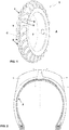
Figures 1 and 2 relate to an exemplary agricultural tyre which can be manufactured by a preferred embodiment of the method according the present invention, such figures showing a perspective front view and a partial cross-sectional view according to an axial plane of said tyre, respectively; - ▪
Figure 3 shows a schematic representation of a sequence of manufacturing steps according to the aforementioned preferred embodiment of the method; - ▪
Figure 3A shows a perspective view of a block or bar used in the method ofFigure 3 ; - ▪
Figure 3B shows a perspective frontal view of an intermediate product having a tyre case, tyre belts or plies and bars or blocks applied thereon according to the method ofFigure 3 , which intermediate product is being formed onto a drum; - ▪
Figure 3C shows a perspective frontal view of a subsequent intermediate product having also a tread ribbon applied onto the bars according to the method ofFigure 3 ; - ▪
Figure 3D shows a perspective frontal view of a final intermediate product ready for a moulding step according to the method ofFigure 3 ; and - ▪
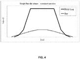
Figure 4 shows a preferred embodiment of an exemplary cross-sectional profile of the bar ofFigure 3A . - With reference to
Figures 1 and 2 , anagricultural tyre 1 has a central axis of rotation A. A rolling direction oftyre 1 is denoted by 7. -
Tyre 1 comprises atoroidal casing 2, which extends about a central axis of rotation A and supports tread belts, or plies, 3 wound aboutcasing 2. -
Tyre 1 comprises a tread, globally denoted by 4, arranged aboutcasing 2 and overbelts 3 according to a toroidal configuration. Tread 4 comprises atread base 5, which completely coverscasing 2 andbelts 3, and a plurality oflugs 6.Lugs 6 project upwards (i.e. extend radially outwards) fromtread base 5 and are arranged substantially crosswise with respect to a tyre travelling direction. - Typically, lugs 6 are arranged symmetrically about axis of rotation A.
- In the present embodiment, each
lug 6 curves from a centreline C oftyre 1 to a corresponding shoulder and has a cross-sectional shape tapering away fromtread base 5. - Each
lug 6 has alateral portion 8 at a shoulder oftyre 1 and acentral portion 9 located in the central area oftyre 1. In the present embodiment, eachlug 6 is thinner atcentral portion 9 and thicker atlateral portion 8. In the example provided,central portion 9 of eachlug 6 has a greater curvature than lateral portion 8 (lateral portion 8 may also be assumed to be substantially straight). - As will be explained in detail shortly, tread
base 5 is obtained by a moulding and curing process from a rubber ribbon blank. Eachlug 6 is obtained by the same mounding and curing process as a superimposition of said rubber ribbon blank with a respective block or bar. - The manufacturing method described below allows
tread base 5 to be of substantially constant thickness. - The manufacturing method of
tyre 1 is shown schematically inFigures 3 and 3A to 3D. - In particular, casing 2 can be produced, in a conventional mode, on a
building unit 101 and subsequently mounted onto abuilding drum 102 of a Tyre Assembly Machine (TAM). - Upon building
drum 102,tread belts 3 are applied ontocasing 2. - In a
conventional unit 103, tread rubber is mixed and extruded (or calandered) into astrip 260. - In the same or in a
separate unit 104, extruded (or calandered)strip 260 is cut into green tread bars (or blocks or elements) 206 (Figure 3A ). Eachbar 206 has aninner portion 209 corresponding tocentral portion 9 offinal lug 6 and anouter portion 208 corresponding tolateral portion 8 offinal lug 6. - Tread
belts 3 and treadbars 206 can assembled together directly ontodrum 102, or they can be joined beforehand (i.e. "off-line") and subsequently placed on TAM and assembled withcasing 2 andbelts 3. -
Bars 206 are lied uponbelts 3 according to a selected arrangement and predetermined relative angles (Figure 3B ). -
Bars 206 can be joined tobelts 3 according to several processes, e.g. by heating, by interposition of chemical compounds or by any other known method for increasing rubber stitching and tackiness properties. - Subsequently, a
tread ribbon 200 is would ontobars 206 lied upon drum 102 (Figure 3C ). To this aim, tread rubber is mixed and extruded (or calandered) in agreen tread ribbon 200, for example in thesame unit 103 mentioned above.Ribbon 200 can be applied by aRibbon Tread Applicator 106, already known per se in the relevant field. - Thereafter, the tyre to be built is removed from drum 102 (
Figure 3D ) and placed in amould 105, wherein vulcanization (also using a press) takes place according to conventional means and modes. -
Strip 260 and/orribbon 200 can also be manufactured in advance and stored in coils. - With reference to
Figure 3A and4 , it will be appreciated that dimensions and shape ofstrip 260 andbars 206 are not equal to the mould lug: they may have a lower height and a wider base, eventually by defining almost same volume. Similarly, sharp outermost edges can be avoided. - Still with reference to
Figure 3A , eachbar 206 can have a constant cross-section, preferably with a cut angle α (and bare angle γ as well) common for the two end cross-sections. In this way, the cutting operation is simplified and rubber wastes are avoided. - Generally speaking, the manufacturing method according to the present disclosure is simplified with respect to the prior art. In particular, preparation and winding of
tread ribbon 200 is easier than manufacturing and arranging tread blank below blocks according to the known methods. - It will be appreciated that the above method avoids the need for assembling tread blank and bars. In fact, application of
bars 206 on tread plies 3 is done before application ofribbon 200. - As already pointed out, the method disclosed allows an important reduction of excess rubber for the tread base with respect to the prior art.
- Application of lubricants or other additives upon the semi-manufactured tread before vulcanization to favour air flow and rubber detachment is possible.
- It will be appreciated that the method of the invention can be used either to build a new tyre or to regenerate the tread of a used one.
- The present invention has been described so far with reference to preferred embodiments. It is intended that there may be other embodiments which refer to the same inventive concept and fall within the scope of the following claims.
Claims (12)
- A method of manufacturing a tyre tread (4),
the tread (4) comprising a tread base (5) and a number of lugs (6), each of which projects upwards from the tread base (5) and extends substantially crosswise to a travelling direction of the tyre,
the method comprising the steps of:(a) proving a tyre casing (2) and tread belts (3);(b) arranging a plurality of rubber blocks (206) onto said tread belts (3), each of said rubber blocks (206) being configured to make a respective lug (6) of the final tread (4);(c) winding a rubber ribbon (200) about said rubber blocks (206) and tread belts (3) arranged onto a drum (102) so as to shield said rubber blocks (206);(d) curing said rubber blocks (206) together with said wound ribbon (200) in a curing mould (105) negatively reproducing a desired pattern of the tread (4). - The method according to claim 1, wherein each of said blocks (206) has an inner wall (209) and an outer wall (208) substantially parallel one another.
- The method according to any of the preceding claims, wherein said rubber blocks (206) are made of a different rubber compound or mixture with respect to said ribbon (200).
- The method according to any of the preceding claims, wherein said step (b) provides an operation of increasing rubber stitching properties of said rubber blocks (206).
- The method according to any of the preceding claims, wherein said step (b) provides assembling said rubber blocks (206) onto said tread belts (3) directly onto a construction drum (102).
- The method according to any of the preceding claims, wherein, in said step (b), each of said rubber blocks (206) is arranged with an outer wall (208) located at a shoulder of the tread to be formed (4) and an inner wall (209) opposite the outer wall (208) and located in a central area of the tread (4) to be formed.
- The method according to any of the preceding claims, wherein, before said step (b), there are provided further steps of:▪ extruding (or calandering) a continuous rubber strip (260) having a cross-section corresponding to transversal section of said rubber blocks (206);▪ cutting rubber blocks (206) off said continuous rubber strip (260), preferably by an inclined crosswise cut.
- The method according to any of the preceding claims, which is a method of regenerating used tyre treads.
- The method according to any of the preceding claims, wherein said tyre is an agricultural tyre (1), in particular an agricultural pneumatic tyre.
- The method according to any of the preceding claims, wherein, in said step (c), each of said rubber blocks (206) is arranged so as to extend from a shoulder portion to a portion at a distance from the tyre centerline or from a shoulder portion to a portion beyond the tyre centerline.
- The method according to any of the preceding claims, wherein said step (c) is performed onto a TAM (Tyre Assembly Machine) drum, onto a TAM server or offline.
- An apparatus for manufacturing a tyre (1),
the tyre including a tread (4) comprising a tread base (5) and a number of lugs (6), each of which projects upwards from the tread base (5) and extends substantially crosswise to a travelling direction of the tyre,
the apparatus comprising the following units arranged in an operative sequence:▪ a rubber mixing and extruding unit (103) configured to output an extruded or calandered ribbon (200) for making the tread base (5) and an extruded or calandered strip (260) for making rubber blocks (206), each of said rubber blocks (206) being configured to make a respective lug (6) of the final tread (4);▪ a drum unit (102) configured to allow a tread casing (2), tread belts (3) and rubber blocks (206) be arranged one upon the other;▪ a ribbon tread applicator (106), configured to wind the ribbon (200) about said rubber blocks (206) so as to shield said rubber blocks (206);▪ a curing unit (105) of said rubber blocks (206) and wound ribbon (200), which curing unit (105) comprises a mould negatively reproducing a desired pattern of the tread (4).
Applications Claiming Priority (2)
| Application Number | Priority Date | Filing Date | Title |
|---|---|---|---|
| IT102016000096381A IT201600096381A1 (en) | 2016-09-26 | 2016-09-26 | MANUFACTURING METHOD OF A TIRE TREAD |
| PCT/EP2017/073925 WO2018055044A1 (en) | 2016-09-26 | 2017-09-21 | Method and apparatus for manufacturing a tyre tread and a tyre |
Publications (2)
| Publication Number | Publication Date |
|---|---|
| EP3515697A1 EP3515697A1 (en) | 2019-07-31 |
| EP3515697B1 true EP3515697B1 (en) | 2019-12-25 |
Family
ID=57909967
Family Applications (1)
| Application Number | Title | Priority Date | Filing Date |
|---|---|---|---|
| EP17768814.0A Active EP3515697B1 (en) | 2016-09-26 | 2017-09-21 | Method and apparatus for manufacturing a tyre tread and a tyre |
Country Status (4)
| Country | Link |
|---|---|
| US (2) | US11420406B2 (en) |
| EP (1) | EP3515697B1 (en) |
| IT (1) | IT201600096381A1 (en) |
| WO (1) | WO2018055044A1 (en) |
Family Cites Families (15)
| Publication number | Priority date | Publication date | Assignee | Title |
|---|---|---|---|---|
| GB1150840A (en) * | 1966-08-03 | 1969-05-07 | Bradley Eugene Ragan | Renewed heavy duty tire and method of building a lugged tread thereon |
| US3993521A (en) * | 1974-09-27 | 1976-11-23 | Harrelson Rubber Company | Lugged vehicle tire, and method of building same |
| DE3424732C1 (en) * | 1984-07-05 | 1985-11-21 | Hüls AG, 4370 Marl | Heat-vulcanizable treads for the production of treads for automotive pneumatic tires |
| JP3352045B2 (en) * | 1999-03-04 | 2002-12-03 | 住友ゴム工業株式会社 | Rubber strip for forming tire rubber member, tire using the same, and rubber strip manufacturing apparatus |
| JP3566915B2 (en) * | 2000-09-07 | 2004-09-15 | 住友ゴム工業株式会社 | Method of manufacturing rubber member for tire |
| JP4698601B2 (en) * | 2004-10-21 | 2011-06-08 | 株式会社ブリヂストン | Belt-like member pasting device and pasting method |
| EP2296867B1 (en) * | 2008-04-23 | 2015-05-27 | MICHELIN Recherche et Technique S.A. | Method of forming a multi-layered tire component |
| JP2012521320A (en) * | 2009-03-20 | 2012-09-13 | イー・アイ・デュポン・ドウ・ヌムール・アンド・カンパニー | Tire tread block composition |
| US20110146885A1 (en) * | 2009-12-23 | 2011-06-23 | D Sidocky Richard Michael | Method for forming stratified rubber article |
| EP2588300B1 (en) * | 2010-06-29 | 2015-10-28 | Pirelli Tyre S.p.A. | Process and plant for producing tyres for vehicle wheels |
| ITTO20120353A1 (en) * | 2012-04-20 | 2013-10-21 | Bridgestone Europ Nv | METHOD AND PLANT FOR THE PRODUCTION OF A TREAD STRIP OF A TIRE PROVIDED WITH BARS |
| ITTO20120354A1 (en) * | 2012-04-20 | 2013-10-21 | Bridgestone Europ Nv | METHOD AND PRODUCTION PLANT TO CARRY OUT A TREAD STRIP OF A TIRE PROVIDED WITH BARS |
| EP2855171A4 (en) * | 2012-05-25 | 2016-01-13 | Michelin & Cie | METHOD AND TIRE FOR IMPROVING UNIFORMITY AND ENDURANCE OF AGGRESSIVE BEARING PATTERN DESIGN USING LAYER APPLICATION TECHNIQUE |
| US20140034199A1 (en) * | 2012-07-31 | 2014-02-06 | Bridgestone Americas Tire Operations, Llc | Tire with laminate |
| US20150013871A1 (en) * | 2013-07-15 | 2015-01-15 | Bridgestone Americas Tire Operations, Llc | Compression Molded Green Rubber Component and Method for Manufacturing the Same |
-
2016
- 2016-09-26 IT IT102016000096381A patent/IT201600096381A1/en unknown
-
2017
- 2017-09-21 EP EP17768814.0A patent/EP3515697B1/en active Active
- 2017-09-21 WO PCT/EP2017/073925 patent/WO2018055044A1/en not_active Ceased
- 2017-09-21 US US16/334,304 patent/US11420406B2/en active Active
-
2022
- 2022-07-19 US US17/868,150 patent/US12011894B2/en active Active
Non-Patent Citations (1)
| Title |
|---|
| None * |
Also Published As
| Publication number | Publication date |
|---|---|
| US20220347955A1 (en) | 2022-11-03 |
| US11420406B2 (en) | 2022-08-23 |
| WO2018055044A1 (en) | 2018-03-29 |
| US12011894B2 (en) | 2024-06-18 |
| EP3515697A1 (en) | 2019-07-31 |
| US20190217565A1 (en) | 2019-07-18 |
| IT201600096381A1 (en) | 2018-03-26 |
Similar Documents
| Publication | Publication Date | Title |
|---|---|---|
| RU2628864C2 (en) | Tire with preliminary professional protector and method of its manufacture | |
| EP1256439A2 (en) | Apparatus for producing an unvulcanized rubber element for tires and element obtained thereby | |
| JP2014504570A (en) | Custom precure type recycled tire | |
| MX2012014113A (en) | Process and plant for producing tyres for vehicle wheels. | |
| JP2008284815A (en) | Pneumatic tire and manufacturing method thereof | |
| US12011894B2 (en) | Method and apparatus for manufacturing a tyre tread and a tyre | |
| EP2121294B1 (en) | Process for manufaturing tyres by application of strips having different widths | |
| EP1512524B1 (en) | Method for manufacturing a tyre carcass | |
| CN104379334B (en) | Produce the method and system of the tyre surface of tire with transverse pattern portion | |
| US7972456B2 (en) | Method of producing tire | |
| CN110891758B (en) | Method of manufacturing improved pneumatic tire | |
| EP2014451A1 (en) | Method of manufacturing a radial tyre | |
| EP3475070B1 (en) | Method for producing a solid rubber tyre and solid rubber tyre produced according to said method | |
| KR100768600B1 (en) | Tire semifinished product manufacturing apparatus and method | |
| KR100814159B1 (en) | Pneumatic Tire Manufacturing Method | |
| CN104364073B (en) | Method and system for manufacturing a tread for a tire having a lug portion | |
| RU2669848C2 (en) | Method of producing tyre tread with lugs and system therefor | |
| US7635444B2 (en) | Method of molding a tire | |
| CA2934228A1 (en) | Precured tire tread having prepared edge and method of making same | |
| JP2011005907A (en) | Pneumatic tire and method for manufacturing the same | |
| WO2019123361A1 (en) | Process and apparatus for manufacturing a mousse for vehicle wheels |
Legal Events
| Date | Code | Title | Description |
|---|---|---|---|
| STAA | Information on the status of an ep patent application or granted ep patent |
Free format text: STATUS: UNKNOWN |
|
| STAA | Information on the status of an ep patent application or granted ep patent |
Free format text: STATUS: THE INTERNATIONAL PUBLICATION HAS BEEN MADE |
|
| PUAI | Public reference made under article 153(3) epc to a published international application that has entered the european phase |
Free format text: ORIGINAL CODE: 0009012 |
|
| STAA | Information on the status of an ep patent application or granted ep patent |
Free format text: STATUS: REQUEST FOR EXAMINATION WAS MADE |
|
| GRAP | Despatch of communication of intention to grant a patent |
Free format text: ORIGINAL CODE: EPIDOSNIGR1 |
|
| STAA | Information on the status of an ep patent application or granted ep patent |
Free format text: STATUS: GRANT OF PATENT IS INTENDED |
|
| 17P | Request for examination filed |
Effective date: 20190415 |
|
| AK | Designated contracting states |
Kind code of ref document: A1 Designated state(s): AL AT BE BG CH CY CZ DE DK EE ES FI FR GB GR HR HU IE IS IT LI LT LU LV MC MK MT NL NO PL PT RO RS SE SI SK SM TR |
|
| AX | Request for extension of the european patent |
Extension state: BA ME |
|
| DAV | Request for validation of the european patent (deleted) | ||
| DAX | Request for extension of the european patent (deleted) | ||
| INTG | Intention to grant announced |
Effective date: 20190722 |
|
| GRAS | Grant fee paid |
Free format text: ORIGINAL CODE: EPIDOSNIGR3 |
|
| GRAA | (expected) grant |
Free format text: ORIGINAL CODE: 0009210 |
|
| STAA | Information on the status of an ep patent application or granted ep patent |
Free format text: STATUS: THE PATENT HAS BEEN GRANTED |
|
| AK | Designated contracting states |
Kind code of ref document: B1 Designated state(s): AL AT BE BG CH CY CZ DE DK EE ES FI FR GB GR HR HU IE IS IT LI LT LU LV MC MK MT NL NO PL PT RO RS SE SI SK SM TR |
|
| REG | Reference to a national code |
Ref country code: GB Ref legal event code: FG4D |
|
| REG | Reference to a national code |
Ref country code: CH Ref legal event code: EP |
|
| REG | Reference to a national code |
Ref country code: AT Ref legal event code: REF Ref document number: 1216701 Country of ref document: AT Kind code of ref document: T Effective date: 20200115 |
|
| REG | Reference to a national code |
Ref country code: DE Ref legal event code: R096 Ref document number: 602017010199 Country of ref document: DE |
|
| REG | Reference to a national code |
Ref country code: IE Ref legal event code: FG4D |
|
| REG | Reference to a national code |
Ref country code: NL Ref legal event code: MP Effective date: 20191225 |
|
| PG25 | Lapsed in a contracting state [announced via postgrant information from national office to epo] |
Ref country code: FI Free format text: LAPSE BECAUSE OF FAILURE TO SUBMIT A TRANSLATION OF THE DESCRIPTION OR TO PAY THE FEE WITHIN THE PRESCRIBED TIME-LIMIT Effective date: 20191225 Ref country code: BG Free format text: LAPSE BECAUSE OF FAILURE TO SUBMIT A TRANSLATION OF THE DESCRIPTION OR TO PAY THE FEE WITHIN THE PRESCRIBED TIME-LIMIT Effective date: 20200325 Ref country code: NO Free format text: LAPSE BECAUSE OF FAILURE TO SUBMIT A TRANSLATION OF THE DESCRIPTION OR TO PAY THE FEE WITHIN THE PRESCRIBED TIME-LIMIT Effective date: 20200325 Ref country code: GR Free format text: LAPSE BECAUSE OF FAILURE TO SUBMIT A TRANSLATION OF THE DESCRIPTION OR TO PAY THE FEE WITHIN THE PRESCRIBED TIME-LIMIT Effective date: 20200326 Ref country code: LV Free format text: LAPSE BECAUSE OF FAILURE TO SUBMIT A TRANSLATION OF THE DESCRIPTION OR TO PAY THE FEE WITHIN THE PRESCRIBED TIME-LIMIT Effective date: 20191225 Ref country code: SE Free format text: LAPSE BECAUSE OF FAILURE TO SUBMIT A TRANSLATION OF THE DESCRIPTION OR TO PAY THE FEE WITHIN THE PRESCRIBED TIME-LIMIT Effective date: 20191225 Ref country code: LT Free format text: LAPSE BECAUSE OF FAILURE TO SUBMIT A TRANSLATION OF THE DESCRIPTION OR TO PAY THE FEE WITHIN THE PRESCRIBED TIME-LIMIT Effective date: 20191225 |
|
| REG | Reference to a national code |
Ref country code: LT Ref legal event code: MG4D |
|
| PG25 | Lapsed in a contracting state [announced via postgrant information from national office to epo] |
Ref country code: HR Free format text: LAPSE BECAUSE OF FAILURE TO SUBMIT A TRANSLATION OF THE DESCRIPTION OR TO PAY THE FEE WITHIN THE PRESCRIBED TIME-LIMIT Effective date: 20191225 Ref country code: RS Free format text: LAPSE BECAUSE OF FAILURE TO SUBMIT A TRANSLATION OF THE DESCRIPTION OR TO PAY THE FEE WITHIN THE PRESCRIBED TIME-LIMIT Effective date: 20191225 |
|
| PG25 | Lapsed in a contracting state [announced via postgrant information from national office to epo] |
Ref country code: AL Free format text: LAPSE BECAUSE OF FAILURE TO SUBMIT A TRANSLATION OF THE DESCRIPTION OR TO PAY THE FEE WITHIN THE PRESCRIBED TIME-LIMIT Effective date: 20191225 |
|
| PG25 | Lapsed in a contracting state [announced via postgrant information from national office to epo] |
Ref country code: NL Free format text: LAPSE BECAUSE OF FAILURE TO SUBMIT A TRANSLATION OF THE DESCRIPTION OR TO PAY THE FEE WITHIN THE PRESCRIBED TIME-LIMIT Effective date: 20191225 Ref country code: EE Free format text: LAPSE BECAUSE OF FAILURE TO SUBMIT A TRANSLATION OF THE DESCRIPTION OR TO PAY THE FEE WITHIN THE PRESCRIBED TIME-LIMIT Effective date: 20191225 Ref country code: RO Free format text: LAPSE BECAUSE OF FAILURE TO SUBMIT A TRANSLATION OF THE DESCRIPTION OR TO PAY THE FEE WITHIN THE PRESCRIBED TIME-LIMIT Effective date: 20191225 Ref country code: CZ Free format text: LAPSE BECAUSE OF FAILURE TO SUBMIT A TRANSLATION OF THE DESCRIPTION OR TO PAY THE FEE WITHIN THE PRESCRIBED TIME-LIMIT Effective date: 20191225 Ref country code: PT Free format text: LAPSE BECAUSE OF FAILURE TO SUBMIT A TRANSLATION OF THE DESCRIPTION OR TO PAY THE FEE WITHIN THE PRESCRIBED TIME-LIMIT Effective date: 20200520 |
|
| PG25 | Lapsed in a contracting state [announced via postgrant information from national office to epo] |
Ref country code: SM Free format text: LAPSE BECAUSE OF FAILURE TO SUBMIT A TRANSLATION OF THE DESCRIPTION OR TO PAY THE FEE WITHIN THE PRESCRIBED TIME-LIMIT Effective date: 20191225 Ref country code: IS Free format text: LAPSE BECAUSE OF FAILURE TO SUBMIT A TRANSLATION OF THE DESCRIPTION OR TO PAY THE FEE WITHIN THE PRESCRIBED TIME-LIMIT Effective date: 20200425 Ref country code: SK Free format text: LAPSE BECAUSE OF FAILURE TO SUBMIT A TRANSLATION OF THE DESCRIPTION OR TO PAY THE FEE WITHIN THE PRESCRIBED TIME-LIMIT Effective date: 20191225 |
|
| REG | Reference to a national code |
Ref country code: DE Ref legal event code: R097 Ref document number: 602017010199 Country of ref document: DE |
|
| PG25 | Lapsed in a contracting state [announced via postgrant information from national office to epo] |
Ref country code: DK Free format text: LAPSE BECAUSE OF FAILURE TO SUBMIT A TRANSLATION OF THE DESCRIPTION OR TO PAY THE FEE WITHIN THE PRESCRIBED TIME-LIMIT Effective date: 20191225 Ref country code: ES Free format text: LAPSE BECAUSE OF FAILURE TO SUBMIT A TRANSLATION OF THE DESCRIPTION OR TO PAY THE FEE WITHIN THE PRESCRIBED TIME-LIMIT Effective date: 20191225 |
|
| PLBE | No opposition filed within time limit |
Free format text: ORIGINAL CODE: 0009261 |
|
| STAA | Information on the status of an ep patent application or granted ep patent |
Free format text: STATUS: NO OPPOSITION FILED WITHIN TIME LIMIT |
|
| REG | Reference to a national code |
Ref country code: AT Ref legal event code: MK05 Ref document number: 1216701 Country of ref document: AT Kind code of ref document: T Effective date: 20191225 |
|
| 26N | No opposition filed |
Effective date: 20200928 |
|
| PG25 | Lapsed in a contracting state [announced via postgrant information from national office to epo] |
Ref country code: AT Free format text: LAPSE BECAUSE OF FAILURE TO SUBMIT A TRANSLATION OF THE DESCRIPTION OR TO PAY THE FEE WITHIN THE PRESCRIBED TIME-LIMIT Effective date: 20191225 Ref country code: IT Free format text: LAPSE BECAUSE OF FAILURE TO SUBMIT A TRANSLATION OF THE DESCRIPTION OR TO PAY THE FEE WITHIN THE PRESCRIBED TIME-LIMIT Effective date: 20191225 |
|
| PG25 | Lapsed in a contracting state [announced via postgrant information from national office to epo] |
Ref country code: PL Free format text: LAPSE BECAUSE OF FAILURE TO SUBMIT A TRANSLATION OF THE DESCRIPTION OR TO PAY THE FEE WITHIN THE PRESCRIBED TIME-LIMIT Effective date: 20191225 |
|
| REG | Reference to a national code |
Ref country code: CH Ref legal event code: PL |
|
| REG | Reference to a national code |
Ref country code: BE Ref legal event code: MM Effective date: 20200930 |
|
| PG25 | Lapsed in a contracting state [announced via postgrant information from national office to epo] |
Ref country code: LU Free format text: LAPSE BECAUSE OF NON-PAYMENT OF DUE FEES Effective date: 20200921 |
|
| PG25 | Lapsed in a contracting state [announced via postgrant information from national office to epo] |
Ref country code: BE Free format text: LAPSE BECAUSE OF NON-PAYMENT OF DUE FEES Effective date: 20200930 Ref country code: CH Free format text: LAPSE BECAUSE OF NON-PAYMENT OF DUE FEES Effective date: 20200930 Ref country code: IE Free format text: LAPSE BECAUSE OF NON-PAYMENT OF DUE FEES Effective date: 20200921 Ref country code: LI Free format text: LAPSE BECAUSE OF NON-PAYMENT OF DUE FEES Effective date: 20200930 |
|
| GBPC | Gb: european patent ceased through non-payment of renewal fee |
Effective date: 20210921 |
|
| PG25 | Lapsed in a contracting state [announced via postgrant information from national office to epo] |
Ref country code: TR Free format text: LAPSE BECAUSE OF FAILURE TO SUBMIT A TRANSLATION OF THE DESCRIPTION OR TO PAY THE FEE WITHIN THE PRESCRIBED TIME-LIMIT Effective date: 20191225 Ref country code: MT Free format text: LAPSE BECAUSE OF FAILURE TO SUBMIT A TRANSLATION OF THE DESCRIPTION OR TO PAY THE FEE WITHIN THE PRESCRIBED TIME-LIMIT Effective date: 20191225 Ref country code: CY Free format text: LAPSE BECAUSE OF FAILURE TO SUBMIT A TRANSLATION OF THE DESCRIPTION OR TO PAY THE FEE WITHIN THE PRESCRIBED TIME-LIMIT Effective date: 20191225 |
|
| PG25 | Lapsed in a contracting state [announced via postgrant information from national office to epo] |
Ref country code: MK Free format text: LAPSE BECAUSE OF FAILURE TO SUBMIT A TRANSLATION OF THE DESCRIPTION OR TO PAY THE FEE WITHIN THE PRESCRIBED TIME-LIMIT Effective date: 20191225 Ref country code: MC Free format text: LAPSE BECAUSE OF FAILURE TO SUBMIT A TRANSLATION OF THE DESCRIPTION OR TO PAY THE FEE WITHIN THE PRESCRIBED TIME-LIMIT Effective date: 20191225 |
|
| PG25 | Lapsed in a contracting state [announced via postgrant information from national office to epo] |
Ref country code: GB Free format text: LAPSE BECAUSE OF NON-PAYMENT OF DUE FEES Effective date: 20210921 |
|
| P01 | Opt-out of the competence of the unified patent court (upc) registered |
Effective date: 20230511 |
|
| PG25 | Lapsed in a contracting state [announced via postgrant information from national office to epo] |
Ref country code: SI Free format text: LAPSE BECAUSE OF FAILURE TO SUBMIT A TRANSLATION OF THE DESCRIPTION OR TO PAY THE FEE WITHIN THE PRESCRIBED TIME-LIMIT Effective date: 20191225 |
|
| PGFP | Annual fee paid to national office [announced via postgrant information from national office to epo] |
Ref country code: DE Payment date: 20250820 Year of fee payment: 9 |
|
| PGFP | Annual fee paid to national office [announced via postgrant information from national office to epo] |
Ref country code: FR Payment date: 20250821 Year of fee payment: 9 |