EP3515315B1 - Ultraschallsonde, ultraschallbildgebungsvorrichtung, ultraschallbildgebungssystem und verfahren zur steuerung davon - Google Patents
Ultraschallsonde, ultraschallbildgebungsvorrichtung, ultraschallbildgebungssystem und verfahren zur steuerung davon Download PDFInfo
- Publication number
- EP3515315B1 EP3515315B1 EP17853286.7A EP17853286A EP3515315B1 EP 3515315 B1 EP3515315 B1 EP 3515315B1 EP 17853286 A EP17853286 A EP 17853286A EP 3515315 B1 EP3515315 B1 EP 3515315B1
- Authority
- EP
- European Patent Office
- Prior art keywords
- ultrasound
- emission angles
- blood flow
- speed
- probe
- Prior art date
- Legal status (The legal status is an assumption and is not a legal conclusion. Google has not performed a legal analysis and makes no representation as to the accuracy of the status listed.)
- Active
Links
Images


Classifications
-
- A—HUMAN NECESSITIES
- A61—MEDICAL OR VETERINARY SCIENCE; HYGIENE
- A61B—DIAGNOSIS; SURGERY; IDENTIFICATION
- A61B5/00—Measuring for diagnostic purposes; Identification of persons
- A61B5/02—Detecting, measuring or recording for evaluating the cardiovascular system, e.g. pulse, heart rate, blood pressure or blood flow
- A61B5/026—Measuring blood flow
-
- A—HUMAN NECESSITIES
- A61—MEDICAL OR VETERINARY SCIENCE; HYGIENE
- A61B—DIAGNOSIS; SURGERY; IDENTIFICATION
- A61B8/00—Diagnosis using ultrasonic, sonic or infrasonic waves
- A61B8/06—Measuring blood flow
-
- A—HUMAN NECESSITIES
- A61—MEDICAL OR VETERINARY SCIENCE; HYGIENE
- A61B—DIAGNOSIS; SURGERY; IDENTIFICATION
- A61B8/00—Diagnosis using ultrasonic, sonic or infrasonic waves
- A61B8/13—Tomography
- A61B8/14—Echo-tomography
-
- A—HUMAN NECESSITIES
- A61—MEDICAL OR VETERINARY SCIENCE; HYGIENE
- A61B—DIAGNOSIS; SURGERY; IDENTIFICATION
- A61B8/00—Diagnosis using ultrasonic, sonic or infrasonic waves
- A61B8/13—Tomography
- A61B8/14—Echo-tomography
- A61B8/145—Echo-tomography characterised by scanning multiple planes
-
- A—HUMAN NECESSITIES
- A61—MEDICAL OR VETERINARY SCIENCE; HYGIENE
- A61B—DIAGNOSIS; SURGERY; IDENTIFICATION
- A61B8/00—Diagnosis using ultrasonic, sonic or infrasonic waves
- A61B8/44—Constructional features of the ultrasonic, sonic or infrasonic diagnostic device
- A61B8/4444—Constructional features of the ultrasonic, sonic or infrasonic diagnostic device related to the probe
- A61B8/4472—Wireless probes
-
- A—HUMAN NECESSITIES
- A61—MEDICAL OR VETERINARY SCIENCE; HYGIENE
- A61B—DIAGNOSIS; SURGERY; IDENTIFICATION
- A61B8/00—Diagnosis using ultrasonic, sonic or infrasonic waves
- A61B8/44—Constructional features of the ultrasonic, sonic or infrasonic diagnostic device
- A61B8/4483—Constructional features of the ultrasonic, sonic or infrasonic diagnostic device characterised by features of the ultrasound transducer
-
- A—HUMAN NECESSITIES
- A61—MEDICAL OR VETERINARY SCIENCE; HYGIENE
- A61B—DIAGNOSIS; SURGERY; IDENTIFICATION
- A61B8/00—Diagnosis using ultrasonic, sonic or infrasonic waves
- A61B8/48—Diagnostic techniques
- A61B8/488—Diagnostic techniques involving Doppler signals
-
- A—HUMAN NECESSITIES
- A61—MEDICAL OR VETERINARY SCIENCE; HYGIENE
- A61B—DIAGNOSIS; SURGERY; IDENTIFICATION
- A61B8/00—Diagnosis using ultrasonic, sonic or infrasonic waves
- A61B8/52—Devices using data or image processing specially adapted for diagnosis using ultrasonic, sonic or infrasonic waves
- A61B8/5215—Devices using data or image processing specially adapted for diagnosis using ultrasonic, sonic or infrasonic waves involving processing of medical diagnostic data
- A61B8/5223—Devices using data or image processing specially adapted for diagnosis using ultrasonic, sonic or infrasonic waves involving processing of medical diagnostic data for extracting a diagnostic or physiological parameter from medical diagnostic data
-
- A—HUMAN NECESSITIES
- A61—MEDICAL OR VETERINARY SCIENCE; HYGIENE
- A61B—DIAGNOSIS; SURGERY; IDENTIFICATION
- A61B8/00—Diagnosis using ultrasonic, sonic or infrasonic waves
- A61B8/54—Control of the diagnostic device
-
- G—PHYSICS
- G01—MEASURING; TESTING
- G01S—RADIO DIRECTION-FINDING; RADIO NAVIGATION; DETERMINING DISTANCE OR VELOCITY BY USE OF RADIO WAVES; LOCATING OR PRESENCE-DETECTING BY USE OF THE REFLECTION OR RERADIATION OF RADIO WAVES; ANALOGOUS ARRANGEMENTS USING OTHER WAVES
- G01S15/00—Systems using the reflection or reradiation of acoustic waves, e.g. sonar systems
- G01S15/88—Sonar systems specially adapted for specific applications
- G01S15/89—Sonar systems specially adapted for specific applications for mapping or imaging
- G01S15/8906—Short-range imaging systems; Acoustic microscope systems using pulse-echo techniques
- G01S15/8909—Short-range imaging systems; Acoustic microscope systems using pulse-echo techniques using a static transducer configuration
- G01S15/8915—Short-range imaging systems; Acoustic microscope systems using pulse-echo techniques using a static transducer configuration using a transducer array
-
- G—PHYSICS
- G01—MEASURING; TESTING
- G01S—RADIO DIRECTION-FINDING; RADIO NAVIGATION; DETERMINING DISTANCE OR VELOCITY BY USE OF RADIO WAVES; LOCATING OR PRESENCE-DETECTING BY USE OF THE REFLECTION OR RERADIATION OF RADIO WAVES; ANALOGOUS ARRANGEMENTS USING OTHER WAVES
- G01S15/00—Systems using the reflection or reradiation of acoustic waves, e.g. sonar systems
- G01S15/88—Sonar systems specially adapted for specific applications
- G01S15/89—Sonar systems specially adapted for specific applications for mapping or imaging
- G01S15/8906—Short-range imaging systems; Acoustic microscope systems using pulse-echo techniques
- G01S15/8979—Combined Doppler and pulse-echo imaging systems
- G01S15/8984—Measuring the velocity vector
-
- A—HUMAN NECESSITIES
- A61—MEDICAL OR VETERINARY SCIENCE; HYGIENE
- A61B—DIAGNOSIS; SURGERY; IDENTIFICATION
- A61B8/00—Diagnosis using ultrasonic, sonic or infrasonic waves
- A61B8/44—Constructional features of the ultrasonic, sonic or infrasonic diagnostic device
- A61B8/4405—Device being mounted on a trolley
-
- A—HUMAN NECESSITIES
- A61—MEDICAL OR VETERINARY SCIENCE; HYGIENE
- A61B—DIAGNOSIS; SURGERY; IDENTIFICATION
- A61B8/00—Diagnosis using ultrasonic, sonic or infrasonic waves
- A61B8/44—Constructional features of the ultrasonic, sonic or infrasonic diagnostic device
- A61B8/4427—Device being portable or laptop-like
-
- A—HUMAN NECESSITIES
- A61—MEDICAL OR VETERINARY SCIENCE; HYGIENE
- A61B—DIAGNOSIS; SURGERY; IDENTIFICATION
- A61B8/00—Diagnosis using ultrasonic, sonic or infrasonic waves
- A61B8/44—Constructional features of the ultrasonic, sonic or infrasonic diagnostic device
- A61B8/4483—Constructional features of the ultrasonic, sonic or infrasonic diagnostic device characterised by features of the ultrasound transducer
- A61B8/4488—Constructional features of the ultrasonic, sonic or infrasonic diagnostic device characterised by features of the ultrasound transducer the transducer being a phased array
-
- A—HUMAN NECESSITIES
- A61—MEDICAL OR VETERINARY SCIENCE; HYGIENE
- A61B—DIAGNOSIS; SURGERY; IDENTIFICATION
- A61B8/00—Diagnosis using ultrasonic, sonic or infrasonic waves
- A61B8/46—Ultrasonic, sonic or infrasonic diagnostic devices with special arrangements for interfacing with the operator or the patient
- A61B8/467—Ultrasonic, sonic or infrasonic diagnostic devices with special arrangements for interfacing with the operator or the patient characterised by special input means
-
- A—HUMAN NECESSITIES
- A61—MEDICAL OR VETERINARY SCIENCE; HYGIENE
- A61B—DIAGNOSIS; SURGERY; IDENTIFICATION
- A61B8/00—Diagnosis using ultrasonic, sonic or infrasonic waves
- A61B8/52—Devices using data or image processing specially adapted for diagnosis using ultrasonic, sonic or infrasonic waves
- A61B8/5207—Devices using data or image processing specially adapted for diagnosis using ultrasonic, sonic or infrasonic waves involving processing of raw data to produce diagnostic data, e.g. for generating an image
Definitions
- an ultrasound probe for obtaining an ultrasound image an ultrasound imaging apparatus for providing the obtained ultrasound image, an ultrasound imaging system including the ultrasound imaging apparatus, and a method of controlling the ultrasound imaging apparatus.
- An ultrasound imaging system which is one of major imaging systems which have been variously applied has non-invasive and non-destructive characteristics and has thus been widely used in the medical field.
- the ultrasound imaging system obtains and displays a two-dimensional (2D) or three-dimensional (3D) ultrasound image of the inside of an object using an ultrasound probe and thus the object may be diagnosed.
- VDI Vector Doppler Imaging
- GDI Color Doppler Imaging
- PWT Plane wave transmissions
- an ultrasound probe according to claim 1 for obtaining an ultrasound image more accurately reflecting a motion of an object an ultrasound imaging apparatus according to claim 2, and a method of controlling the ultrasound imaging according to claim 3.
- an ultrasound probe according to claim 1 is disclosed.
- an ultrasound imaging apparatus according to claim 2 is provided.
- a method of controlling an ultrasound imaging apparatus according to claim 3 is provided.
- an ultrasound image more accurately reflecting a speed of an object in each of directions and a speed of the object may be obtained from an echo ultrasound signal received by emitting a plane wave at different emission angles or at emission angles dependent on each other.
- the number of regions of an object, images of which may be obtained may be increased by emitting a plane wave at various emission angles.
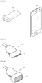
- FIG. 1 is a diagram illustrating an external structure of an ultrasound imaging system including an ultrasound probe and an ultrasound imaging apparatus connected to the ultrasound probe according to a wired or wireless communication method, in accordance with an embodiment.
- FIG. 2 is a diagram illustrating an external structure of an ultrasound imaging system including an ultrasound imaging apparatus embodied differently from the ultrasound imaging apparatus of FIG. 1 , in accordance with an embodiment.
- FIGS. 1 and 2 will be described together below to avoid redundancy.
- an ultrasound imaging system 1 includes an ultrasound probe 100 which emits an ultrasound signal to an object, receives an echo ultrasound signal from the object, and converts the echo ultrasound signal into an electrical signal, and an ultrasound imaging apparatus 200 which is connected to the ultrasound probe 100 according to a wired/wireless communication method and displays an ultrasound image.
- the ultrasound probe 100 may be connected to the ultrasound imaging apparatus 200 according to the wired communication method to receive various signals for controlling the ultrasound probe 100 from the ultrasound imaging apparatus 200. Furthermore, the ultrasound probe 100 may transmit to the ultrasound imaging apparatus 200 either an analog signal or a digital signal corresponding to a received echo ultrasound signal or an ultrasound image reconstructed from the echo ultrasound signal.
- the wired communication method refers to a communication method of transmitting or receiving a signal containing data via wire.
- Examples of the wired communication method include a peripheral component interconnect (PCI), PCI-express, a universal serial bus (USB), etc. but are not limited thereto and may include already known various other methods.
- PCI peripheral component interconnect
- PCI-express PCI-express
- USB universal serial bus
- the ultrasound probe 100 may be connected to the ultrasound imaging apparatus 200 according to the wireless communication method to receive various signals for controlling the ultrasound probe 100 from the ultrasound imaging apparatus 200 or to transmit either an analog signal or a digital signal corresponding to an echo ultrasound signal received by the ultrasound probe 100. Furthermore, the ultrasound probe 100 may transmit information regarding an operating state of the ultrasound probe 100 and the like to the ultrasound imaging apparatus 200.
- the wireless communication method refers to a communication network supporting a wireless communication method of wirelessly transmitting and receiving a signal.
- Examples of the wireless communication method include not only communication methods of transmitting or receiving a wireless signal via a base station, such as third generation (3G) and fourth generation (4G), but also communication methods of directly transmitting or receiving a wireless signal between devices within a predetermined distance, such as a wireless local area network (LAN), Wi-Fi, Bluetooth, Zigbee, Wi-Fi direct (WFD), ultra-wideband (UWB), infrared data association (IrDA), Bluetooth low energy (BLE), and near-field communication (NFC).
- LAN wireless local area network
- Wi-Fi Wireless Fidelity
- Bluetooth Wireless Fidelity
- Zigbee Wi-Fi direct
- UWB ultra-wideband
- IrDA infrared data association
- BLE Bluetooth low energy
- NFC near-field communication
- the wireless communication method is not limited thereto and includes all communication networks supporting exchange of a wireless signal between the ultrasound probe 100 and the ultrasound imaging apparatus 200.
- the wired communication method and the wireless communication method will be hereinafter referred to together as a communication method when there is no need to differentiate them from each other.
- a wired communication network and a wireless communication network will be hereinafter referred to together as a communication network when there is no need to differentiate them from each other.
- the ultrasound imaging apparatus 200 may be embodied in a form generally used in a hospital or the like for an ultrasonic diagnosis as illustrated in FIG. 1 .
- the form of the ultrasound imaging apparatus 200 is not limited to that illustrated in FIG. 1 .
- the ultrasound imaging apparatus 200 may be embodied as not only a laptop computer, a desktop computer, a tablet personal computer (PC) but also as a smartphone illustrated in FIG. 2 .
- the ultrasound imaging apparatus 200 may be embodied as a mobile terminal such as a personal digital assistant (PDA), a watch which is attachable to and detachable from a user's body, or a glasses-type wearable terminal.
- PDA personal digital assistant
- the ultrasound imaging apparatus 200 is not limited thereto and may be any type device which includes a communication module therein to exchange a wire/ wireless signal with an external device according to at least one of the wireless communication method and the wired communication method and which includes a processor therein to perform various arithmetic operations.
- an ultrasound imaging apparatus may be embodied in various forms as described above and embodiments which will be described below are thus not limited thereto.
- the ultrasound imaging apparatus 200 illustrated in FIG. 1 will be described below.
- a display unit 210 and an input unit 220 may be provided.
- the input unit 220 may receive setting information regarding the ultrasound probe 100, various control commands, etc. from a user.
- the setting information regarding the ultrasound probe 100 includes gain information, zoom information, focus information, time gain compensation (TGC) information, depth information, frequency information, power information, frame average information, dynamic range information, etc.
- TGC time gain compensation
- the setting information regarding the ultrasound probe 100 is not limited thereto and may include various information which may be set to obtain an ultrasound image.
- the input unit 220 may receive a control command regarding the ultrasound probe 100 or the ultrasound imaging apparatus 200 from a user.
- the setting information, the control command, etc. described above may be transmitted to the ultrasound probe 100 via a communication network, and the ultrasound probe 100 may be set according to the transmitted information.
- the input unit 220 may be embodied as a keyboard, a foot switch, or a foot pedal.
- the keyboard may be embodied as hardware.
- Such a keyboard may include at least one among a switch, a key, a joystick, and a trackball.
- the keyboard may be embodied as software, e.g., in the form of a graphical user interface. In this case, the keyboard may be displayed on the display unit 210.
- the foot switch or the foot pedal may be provided at the bottom of the ultrasound imaging apparatus 200. A user may control an operation of the ultrasound imaging apparatus 200 using the foot pedal.
- the display unit 210 may display an ultrasound image of a target inner part of an object.
- the ultrasound image displayed on the display unit 210 may be a two-dimensional (2D) or three-dimensional (3D) ultrasound image.
- Various ultrasound images may be displayed according to an operating mode of the ultrasound imaging apparatus 200.
- the display unit 210 may display not only a menu or information for the ultrasound image but also information regarding an operating state of the ultrasound probe 100, etc.
- the display unit 210 may be embodied as, but is not limited to, already-known various display panels, such as a cathode ray tube (CRT), a liquid crystal display (LCD), a light-emitting diode (LED), a plasma display panel (PDP), and an organic light-emitting diode (OLED).
- CTR cathode ray tube
- LCD liquid crystal display
- LED light-emitting diode
- PDP plasma display panel
- OLED organic light-emitting diode
- the display unit 210 may also perform a function of the input unit 220. That is, a user may input various commands through the display unit 210 or the input unit 220.
- virtual input buttons or the like may be displayed on a display of the ultrasound imaging apparatus 200 of FIG. 2 through a graphical user interface and thus a user may input various commands using the virtual input buttons.
- a structure of the ultrasound probe 100 will be described in more detail below.
- FIG. 3 is a diagram illustrating an exterior of an ultrasound probe having a one-dimensional (1D) transducer array, in accordance with an embodiment.
- FIG. 4 is a diagram illustrating an exterior of an ultrasound probe having a 2D transducer array, in accordance with another embodiment. FIGS. 3 and 4 will be described together below to avoid redundancy.
- An ultrasound probe 100 is configured to be in contact with a surface of an object, and may emit an ultrasound signal.
- the ultrasound probe 100 may emit an ultrasound signal into the object according to a control command signal received from an ultrasound imaging apparatus 200, receive an echo ultrasound signal reflected from a specific inner part of the object, and transmit the echo ultrasound signal to the ultrasound imaging apparatus 200.
- the ultrasound probe 100 may transmit an echo ultrasound signal received from the object to the ultrasound imaging apparatus 200 or may obtain an ultrasound image from the echo ultrasound signal and transmit the ultrasound image via a communication network, but is not limited thereto.
- the ultrasound probe 100 may include a transducer which converts an electrical signal into an ultrasound signal or vice versa to transmit an ultrasound wave into an object.
- the transducer may be embodied as a 1D or 2D transducer array having a plurality of transducer elements.
- the transducer may include a 1D transducer array T1 as illustrated in FIG. 3 .
- the transducer may include a 2D transducer array T2 as illustrated in FIG. 4 .
- the transducer elements of the 1D transducer array may convert an ultrasound signal into an electrical signal or vice versa.
- the transducer elements may be embodied as magnetostrictive ultrasonic transducers using a magnetostrictive effect of a magnetic substance, piezoelectric ultrasonic transducers using a piezoelectric effect of a piezoelectric material, piezoelectric micro-machined ultrasonic transducers (pMUTs), or capacitive micro-machined ultrasonic transducers (hereinafter abbreviated as 'cMUTs') which transmit or receive an ultrasound wave using vibration of several hundreds or thousands of micro-machined thin films.
- pMUTs piezoelectric micro-machined ultrasonic transducers
- 'cMUTs' capacitive micro-machined ultrasonic transducers
- the transducers may be arranged linearly or in a convex shape.
- a basic operating principle of the ultrasound probe 100 is the same when the transducers are arranged linearly or in the convex shape.
- ultrasound waves emitted from the transducers have a fan shape and thus a generated ultrasound image may also have a fan shape.
- the transducer of the ultrasound probe 100 may include the 2D transducer array T2 as described above.
- the 2D transducer array T2 When the 2D transducer array T2 is provided, a 3D image of the inside of an object may be obtained.
- the transducer elements of the 2D transducer array are the same as those of the 1D transducer array and are thus not described in detail here. A relationship between the ultrasound probe 100 and the ultrasound imaging apparatus 200 will be described below.
- FIG. 5 is a diagram illustrating a relationship between an ultrasound probe and an ultrasound imaging apparatus in accordance with an embodiment.
- An ultrasound system may include an ultrasound probe 100 and an ultrasound imaging apparatus 200.
- the ultrasound system may emit an ultrasound signal from a surface of an object ob toward a target inner part of the body of the object ob using the ultrasound probe 100, noninvasively obtain a tomographic image of soft tissue of the body or an image of a blood flow using an ultrasound signal reflected from the target inner part, i.e., an echo ultrasound signal, and provide a user with the obtained image.
- the ultrasound probe 100 may emit a plane wave to an object using the 2D transducer array T2.
- the plane wave should be understood as an ultrasound signal having a 2D planar shape.
- the ultrasound probe 100 may receive an echo ultrasound signal reflected from the object ob by emitting the plane wave to the object, and transmit the received echo ultrasound signal to the ultrasound imaging apparatus 200.
- the ultrasound imaging apparatus 200 may include a main controller which performs an image processing process to convert the received echo ultrasound signal into an ultrasound image.
- the main controller may be embodied as hardware, such as a processor or a graphic processor, or software which may be executed on hardware. The main controller will be described in detail below.
- the ultrasound probe 100 may directly convert the echo ultrasound signal into an ultrasound image and transmit the ultrasound image to the ultrasound imaging apparatus 200 as described above.
- the ultrasound probe 100 may include a probe controller embodied as hardware, such as a processor or a graphic processor, or as software which may be executed on hardware to convert the echo ultrasound signal into an ultrasound image.
- the probe controller will be described in detail below.
- the ultrasound probe 100 may transmit the ultrasound image or the echo ultrasound signal to the ultrasound imaging apparatus 200 via a communication network but is not limited thereto.
- the generated ultrasound image may be stored in a memory included in the ultrasound imaging apparatus 200.
- the ultrasound image may be stored in web storage or a cloud server having a storing function on a web. Inner structures of an ultrasound probe and an ultrasound imaging apparatus will be described in more detail below.
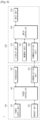
- FIG. 6 is a control block diagram of an ultrasound probe in accordance with an embodiment.
- FIG. 7 is a control block diagram of an ultrasound imaging apparatus in accordance with an embodiment.
- FIG. 8 is a control block diagram of an ultrasound imaging system including an ultrasound probe and an ultrasound imaging apparatus, in accordance with an embodiment.
- FIG. 9 is a diagram illustrating a region of an object, an image of which may be obtained when a plane wave is emitted several times at the same emission angle in accordance with an embodiment, when viewed at a side.
- FIG. 10 is a diagram illustrating a region of an object, an image of which may be obtained when a plane wave is emitted several times at the same emission angle in accordance with an embodiment, when viewed at another side.
- FIG. 9 is a diagram illustrating a region of an object, an image of which may be obtained when a plane wave is emitted several times at the same emission angle in accordance with an embodiment, when viewed at another side.
- FIG. 10 is a diagram illustrating
- FIG. 11 is a diagram illustrating a region of an object, an image of which may be obtained when a plane wave is emitted at different emission angles in accordance with another embodiment, when viewed at a side.
- FIG. 12 is a diagram illustrating a region of an object, an image of which may be obtained when a plane wave is emitted at different emission angles in accordance with another embodiment, when viewed at another side.
- FIG. 13 is a diagram illustrating an angle at which a plane wave is emitted, and an angle at which an echo ultrasound signal is received, in accordance with an embodiment.
- FIG. 14 is a diagram illustrating an angle between a direction of a motion of an object and a direction in which a plane wave is emitted, in accordance with an embodiment. FIGS. 6 to 14 will be described together below to avoid redundancy.
- a case in which a probe controller 140 of an ultrasound probe 100 obtains an ultrasound image through an image processing process and transmits it to the ultrasound imaging apparatus 200 will be described below. All or some of operations performed to obtain an ultrasound image may be performed by a main controller 240 of an ultrasound imaging apparatus 200 but embodiments are not limited thereto.
- the ultrasound probe 100 may include a power supply unit 110 which supplies power to the ultrasound probe 100, a communication unit 120 which transmits various signals to or receives various signals from an external device, a transducer 130 which emits an ultrasound signal to an object and receives an echo ultrasound signal reflected from the object, the probe controller 140 which controls overall operations of the ultrasound probe 100, and a memory unit 150 which stores various types of control data, an echo ultrasound signal, etc. needed to control an operation of the ultrasound probe 100.
- a power supply unit 110 which supplies power to the ultrasound probe 100
- a communication unit 120 which transmits various signals to or receives various signals from an external device
- a transducer 130 which emits an ultrasound signal to an object and receives an echo ultrasound signal reflected from the object
- the probe controller 140 which controls overall operations of the ultrasound probe 100
- a memory unit 150 which stores various types of control data, an echo ultrasound signal, etc. needed to control an operation of the ultrasound probe 100.
- At least one among the communication unit 120, the probe controller 140, and the memory unit 150 may be integrated into a system-on-chip (SoC) embedded in the ultrasound probe 100, and may be operated by a processor.
- SoC system-on-chip
- the number of SoCs included in the ultrasound probe 100 is not limited to one and thus at least one among the communication unit 120, the probe controller 140, and the memory unit 150 is not limited to being integrated into one SoC.
- the power supply unit 110 may supply power to the ultrasound probe 100.
- the power supply unit 110 may supply power by converting electrical energy into chemical energy, accumulating the chemical energy, and converting the accumulated chemical energy into electrical energy.
- the power supply unit 110 may be embodied as a lithium ion battery, a nickel metal hydrogen battery, a polymer battery, or the like.
- the power supply unit 110 in accordance with an embodiment is not limited thereto, and may be embodied as various types of batteries which may be embedded in the ultrasound probe 100 to supply power.
- the power supply unit 110 may be charged by directly connecting it to a charging device according to a wired charging method or may be charged according to a wireless charging method. That is, a method of charging the power supply unit 110 is not limited, and the power supply unit 110 may be charged according to already known various methods.
- the power supply unit 110 may be included in the ultrasound probe 100 if necessary but may not be included in the ultrasound probe 100 and is not limited to that illustrated in FIG. 6 .
- the communication unit 120 may be included in the ultrasound probe 100.
- the communication unit 120 may include one or more elements for establishing wireless or wired communication with an external device.
- the communication unit 120 may include at least one of a wireless communication module having at least one among a short-distance communication module and a mobile communication module, and a wired communication module supporting the wired communication method.
- the short-distance communication module refers to a module for short-distance communication within a predetermined distance.
- the short-distance communication may include, but is not limited to, a wireless LAN, Wi-Fi, Bluetooth, Zigbee, Wi-Fi direct (WFD), ultra-wideband (UWB), infrared data association (IrDA), Bluetooth low energy (BLE), near-Field communication (NFC), or the like.
- the mobile communication module may exchange wireless signals with at least one among a base station, an external terminal, and a server in a mobile communication network.
- the mobile communication module may exchange various types of data with the ultrasound imaging apparatus 200 via the base station through a 3G or 4G communication network.
- the short-distance communication module and the mobile communication module will be hereinafter referred to together as a communication module.
- the wired communication module refers to a module supporting exchange of signals containing data via wire.
- the wired communication module may support at least one among already-known various types of wired communication methods such as peripheral component interconnect (PCI), PCI-express, and a universe serial bus (USB).
- PCI peripheral component interconnect
- PCI-express PCI-express
- USB universe serial bus
- the communication unit 120 may exchange various types of data with the ultrasound imaging apparatus 200 through a communication network.
- the communication unit 120 may transmit or receive data related to diagnosing an object, such as an ultrasound image of the object, echo ultrasound data, Doppler data, etc., through the communication network.
- the communication unit 120 may receive various types of control command signals from the ultrasound imaging apparatus 200. That is, the type of data or a command which the communication unit 120 may exchange with the ultrasound imaging apparatus 200 through a wired/wireless signal is not limited.
- the transducer 130 may be included in the ultrasound probe 100 as described above.
- the transducer 130 may emit an ultrasound signal to an object and receive an echo ultrasound signal reflected from the object.
- the transducer 130 has been described above and is thus not redundantly described here again.
- the transducer 130 which will be described below may be embodied as either a 2D transducer array or a 1D transducer array which may be operated in an altitude direction, and may thus emit a plane wave to the object.
- the transducer 130 may sequentially emit a plane wave at various emission angles or in emission directions according to a control signal from the probe controller 140.
- An emission angle and an emission direction will be hereinafter referred to together as an emission angle when there is no need to differentiate them from each other.
- the transducer 130 may emit a plane wave at the same emission angle a plurality of times and at time intervals, emit the plane wave at different emission angles a plurality of times, or emit the plane wave at emission angles dependent on each other a plurality of times, according to a control signal from the probe controller 140, but embodiments are not limited thereto.
- a region of an object, an image of which may be obtained from an ultrasound image may be the same or different according to an emission angle at which the plane wave is emitted by the transducer 130.
- the region of the object, an image of which may be obtained from the ultrasound image may be a region of the object to which at least three plane waves among a plurality of plane waves are emitted.
- a region of an object, an image of which may be obtained from an ultrasound image may be a region R1 to which these plane waves are emitted.
- the transducer 130 may emit the plane waves P1, P2, and P3 at different emission angles according to a control signal as illustrated in FIGS. 11 and 12 .
- a region of an object, an image of which may be obtained may be a region R2 in which the plane waves P1, P2, and P3 overlap one another.
- a region of an object, an image of which may be obtained by the probe controller 140 is not limited to a plane parallel to a transducer array.
- the probe controller 140 may be included in the ultrasound probe 100.
- the probe controller 140 may control overall operations of the ultrasound probe 100.
- the probe controller 140 may be embodied as at least one of a processor which may perform various processes, such as an image processing process and an operation processing process, and a graphic processor, or embodied as a single component having functions of the above-described processors.
- the probe controller 140 may generate a control signal, and control overall operations of the elements of the ultrasound probe 100 using the generated control signal.
- control data for controlling the elements of the ultrasound probe 100 and control data for performing an image processing process may be stored beforehand in the memory unit 150.
- the probe controller 140 may generate the control signal on the basis of the data stored in the memory unit 150, and control overall operations of the elements of the ultrasound probe 100 using the generated control signal.
- the memory unit 150 will be described in detail below.
- the probe controller 140 may obtain an ultrasound image from an echo ultrasound signal received by the transducer 130.
- the probe controller 140 may obtain the ultrasound image by performing an image processing process on the echo ultrasound signal received by the transducer 130 on the basis of the control data stored in the memory unit 150.
- the ultrasound image may include a gray-scale image obtained by scanning an object according to an amplitude mode (A-mode), a brightness mode (B-mode), or a motion mode (M-mode).
- A-mode amplitude mode
- B-mode brightness mode
- M-mode motion mode
- the ultrasound image may include a Doppler image which expresses a motion of an object according to a Doppler mode using the Doppler effect.
- the Doppler image may be classified as a color Doppler image indicating blood flow, a tissue Doppler image indicating a motion of tissue, a spectral Doppler image indicating a moving speed of an object using a waveform, or the like, according to the type of the object to be diagnosed.
- the color Doppler image may be referred to as a blood flow Doppler image.
- the color Doppler image indicating the flow of blood i.e., blood flow
- blood flow i.e., blood flow
- embodiments which will be described below are not limited thereto and are applicable to all methods of obtaining an ultrasound image indicating a motion of an object.
- the probe controller 140 may obtain a color Doppler image from a received echo ultrasound signal, and control the communication unit 120 to transmit the obtained color Doppler image to the ultrasound imaging apparatus 200.
- a tester may view the color Doppler image using the display unit 210 of the ultrasound imaging apparatus 200 to determine a blood flow speed or rate in a testee's blood vessel.
- the transducer 130 may emit a plane wave P4 at an emission angle ⁇ with respect to x-y axes and an emission angle ⁇ with respect to x-z axes on the basis of a control signal from the probe controller 140, and receive an echo ultrasound signal reflected from an object, i.e., blood.
- the probe controller 140 may determine the speed of blood in a direction perpendicular to the plane wave P4 from the received echo ultrasound signal.
- the speed of blood in a direction in which blood flows i.e., a direction of blood flow, cannot be accurately determined.
- the speed of the motion of the object in various directions is needed to be measured.
- the speed of blood in each of directions should be accurately determined to conduct an accurate diagnosis.
- the ultrasound imaging system 1 may more quickly and accurately calculate not only the speed of blood flow but also the speed of blood flow in each of directions. A method of calculating a blood flow speed and a blood flow speed in each of directions will be described below.
- a Doppler shift frequency of each of echo ultrasound signals received by emitting an ultrasound signal may be calculated by Equation 1 below.
- f d 2 ⁇ f 0 ⁇ v ⁇ cosA C
- f 0 represents the Doppler shift frequency
- f 0 represents a main frequency of the ultrasound signal, i.e., a frequency of the emitted ultrasound signal.
- A represents an angle formed by the ultrasound signal and blood flow, i.e., an angle between a direction in which the ultrasound signal is emitted and a direction in which blood flows
- v represents a blood flow speed
- C represents an ultrasonic velocity in an object, e.g., a living body.
- An emission angle at which the ultrasound signal is emitted may be expressed using two angle parameters.
- a first angle parameter may represent an emission angle of the ultrasound signal on the x-y axes
- a second angle parameter may represent an emission angle of the ultrasound signal on the x-z axes.
- the transducer 130 may emit the plane wave P4 at the emission angle ⁇ with respect to the x-y axes and the emission angle ⁇ with respect to the x-z axes, according to a control signal.
- the first angle parameter may be the emission angle ⁇ with respect to the x-y axes
- the second angle parameter may be the emission angle ⁇ with respect to the x-z axes.
- the transducer 130 may receive an echo ultrasound signal corresponding to the plane wave P4 with respect to a normal of the plane wave P4, i.e., in a vertical direction.
- a speed of an object which may be determined from a Doppler shift frequency inferred from the received echo ultrasound signal by the probe controller 140 may be the speed of the object in a direction of a normal vector D1 of the plane wave P4 illustrated in FIG. 13 .
- an angle A between an ultrasound signal and blood flow may be expressed as illustrated in FIG. 14 .
- the Doppler shift frequency may be calculated by Equation 2 below.
- the Doppler shift frequency may be based on the speed of blood flow in a direction of a vector perpendicular to the plane wave P4, e.g., the normal vector D1 of FIG. 13 .
- the speeds of blood flow in various directions may be needed to determine the speed of blood flow in a direction in which blood actually flows.
- the speeds of blood flow in directions e.g., the speed Vx of blood flow in an x-axis direction, the speed Vy of blood flow in a y-axis direction, and the speed Vz of blood flow in a z-axis direction
- Equation 3 An ultrasound image may be more accurately obtained by determining the speed of blood flow in each of the directions.
- a blood flow speed v and directions in which blood flows i.e., blood flow directions ⁇ and ⁇
- a method of determining the blood flow speed v and the blood flow directions ⁇ and ⁇ from echo ultrasound signals received by emitting a plane wave at three different emission angles and then calculating the speed of blood flow in each of the directions on the basis of the blood flow speed v and the blood flow directions ⁇ and ⁇ will be described below.
- the probe controller 140 may control the transducer 130 to sequentially emit a plurality of plane waves at different emission angles. In this case, the different emission angles are not limited provided they are different from each other.
- the probe controller 140 may control the transducer 130 to emit a plane wave at different emission angles, and store information regarding the emission angles in the memory unit 150.
- the probe controller 140 may control the transducer 130 to emit to an object a first plane wave at an emission angle ⁇ 1 with respect to the x-y axes and an emission angle ⁇ 1 with respect to the x-z axes, a second plane wave at an emission angle ⁇ 2 with respect to the x-y axes and an emission angle ⁇ 2 with respect to the x-z axes, and a third plane wave at an emission angle ⁇ 3 with respect to the x-y axes and an emission angle ⁇ 3 with respect to the x-z axes.
- the emission angles ⁇ 1 and ⁇ 1 will be referred to as first emission angles
- the emission angles ⁇ 2 and ⁇ 2 will be referred to as second emission angles
- the emission angles ⁇ 3 and ⁇ 3 will be referred to as third emission angles.
- the probe controller 140 may emit first to third plane waves such that at least one of x-y axis emission angles between the first emission angles, the second emission angles, and the third emission angles, and a y-axis emission angle is different.
- first angle parameters of the first to third emission angles may be set to be different
- second angle parameters of the first to third emission angles may be set to be different.
- the probe controller 140 may determine a Doppler shift frequency of each of first to third echo ultrasound signals received by sequentially emitting the first to third plane waves on the basis of Equation 2 above.
- a first Doppler shift frequency inferred from the first echo ultrasound signal will be referred to as f d1 .
- a second Doppler shift frequency inferred from the second echo ultrasound signal will be referred to as f d2 .
- a third Doppler shift frequency inferred from the third echo ultrasound signal will be referred to as f d3 .
- the probe controller 140 may individually infer the three first to third Doppler shift frequencies f d1 , f d2 , and f d3 .
- the probe controller 140 have determined beforehand emission angles of plane waves and thus equations related to the first to third Doppler frequencies f d1 , f d2 , and f d3 and including three unknowns v, ⁇ , and ⁇ may be inferred on the basis of Equation 2.
- the probe controller 140 may calculate three unknowns, i.e., variables v, ⁇ , and ⁇ , from three equations through a simultaneous equation process. Accordingly, the probe controller 140 may determine a blood flow speed in each of directions through Equation 3 above while determining a blood flow speed. The probe controller 140 may obtain an ultrasound image accurately reflecting a motion of blood flow on the basis of the blood flow speed and the blood flow speed in each of the directions.
- a method of calculating a blood flow speed, a blood flow speed in each of directions, etc. is not limited to the above-described method.
- a method of calculating a blood flow speed in each of directions from a plane wave emitted at an emission angle four times or more on the basis of a vector decomposition process and inferring a blood flow speed from the calculated blood flow speed in each of the directions will be described below.
- the probe controller 140 emits a plane wave at predetermined emission angles a plurality of times.
- the emission angles and a number of times of emitting the plane wave may be set beforehand.
- the emission angles may vary according to the number of times of emitting the plane wave, and the number of times of emitting the plane wave is four or more.
- the emission angles depend on each other.
- the emission angles ⁇ 1 to ⁇ 4 on the x-y axes among the emission angles are by the following Equation.
- ⁇ 1 ⁇ °
- ⁇ 2 180 ⁇ ⁇ °
- ⁇ 3 180 + ⁇ °
- ⁇ 4 360 ⁇ ⁇ °
- a blood flow speed in the x-axis direction may be determined on the basis of the first to fourth Doppler shift frequencies, as expressed in Equation 6 below.
- f d 1 ⁇ f d 2 ⁇ f d 3 + f d 4 ⁇ 8 ⁇ sin ⁇ ⁇ cos ⁇ ⁇ f 0 ⁇ C v x
- a blood flow speed in the y-axis direction may be determined on the basis of the first to fourth Doppler shift frequencies, as expressed in Equation 7 below.
- f d 1 + f d 2 ⁇ f d 3 ⁇ f d 4 ⁇ 8 ⁇ sin ⁇ ⁇ sin ⁇ ⁇ f 0 ⁇ C v y
- a blood flow speed in the z-axis direction may be determined on the basis of the first to fourth Doppler shift frequencies, as expressed in Equation 8 below.
- f d 1 + f d 2 + f d 3 + f d 4 ⁇ 8 ⁇ cos ⁇ ⁇ f 0 ⁇ C v z
- Equations 2 and 3 the relationship between a blood flow speed in each of the directions and the Doppler shift frequencies may be inferred from Equations 2 and 3, as expressed in Equations 6 to 8.
- the final equations (6) to (8) include information on the three-dimensional vector of the blood flow, and include the velocity information about the X-axis, the Y-axis and the Z-axis of the blood flow. Accordingly, the probe controller 140 may more accurately generate the three-dimensional image based on the information about the three-dimensional vector.
- the probe controller 140 may quickly calculate a blood flow speed for each of vectors, i.e., in each of directions, through a small amount of calculation, and determine a blood flow speed on the basis of the calculated blood flow speed in each of the directions.
- the probe controller 140 may obtain an ultrasound image more accurately indicating a motion of blood on the basis of the calculated blood flow speed and the blood flow speed in each of the directions.
- the memory unit 150 configured to store data may be included in the ultrasound probe 100.
- the memory unit 150 may be embodied as at least one type of storage medium among a flash memory type storage medium, a hard disk type storage medium, a multimedia card micro type storage medium, a card type memory (e.g., an SD or XD memory or the like), a random access memory (RAM), a static random access memory (SRAM), a read-only memory (ROM), an electrically erasable programmable read-only memory (EEPROM), a programmable read-only memory (PROM), a magnetic memory, a magnetic disk, and an optical disc.
- the memory unit 150 is not limited thereto and may be embodied in any form known in the art.
- the memory unit 150 may store data regarding an echo ultrasound signal, data regarding an ultrasound image, etc.
- the memory unit 150 may store control data for controlling the elements of the ultrasound probe 100, control data for an imaging process of obtaining an ultrasound image, etc. but is not limited thereto.
- the ultrasound probe 100 may further include a display unit if necessary.
- the display unit may display information related to an operating state of the ultrasound probe 100, e.g., a power state of the ultrasound probe 100.
- the ultrasound probe 100 may further include an input unit if necessary.
- the input unit may be embodied as a switch, a key, or the like as described above but is not limited thereto.
- a command to power on or off the ultrasound probe 100, etc. may be received from a user via the input unit.
- a control command to change an operating mode of the ultrasound probe 100 may be received via the input unit but embodiments are not limited thereto.
- the ultrasound imaging apparatus 200 may include the display unit 210, the input unit 220, a communication unit 230, the main controller 240, and a memory unit 250.
- the communication unit 230, the main controller 240, and the memory unit 250 may be integrated into an SoC embedded in the ultrasound imaging apparatus 200, and operated by a processor.
- the number of SoCs included in the ultrasound imaging apparatus 200 is not limited to one and thus at least one among the communication unit 230, the main controller 240, and the memory unit 250 is not limited to being integrated into one SoC.
- the display unit 210 and the input unit 220 have been described above and are thus not redundantly described here.
- the display unit 210 may display various types of information.
- the display unit 210 may display an ultrasound image obtained from an echo ultrasound signal through an image processing process.
- a graphical user interface GUI
- the display unit 210 which is a touch screen type display may perform a function of the input unit 220.
- the communication unit 230 may exchange data with an external device via a communication network.
- the communication network includes a wired/wireless communication network.
- the wired/wireless communication network is as described above and is thus not described here again.
- the communication unit 230 may exchange various signals with the ultrasound probe 100 via the communication network as described above. Referring to FIG. 9 , in the ultrasound imaging system 1, the ultrasound probe 100 and the ultrasound imaging apparatus 200 are connected to each other via the communication unit 120 of the ultrasound probe 100 and the communication unit 230 of the ultrasound imaging apparatus 200 to exchange various data with each other. For example, the communication unit 230 may transmit various control commands and receive an echo ultrasound signal or a signal including ultrasound image data reconstructed from the echo ultrasound signal. In addition, the communication unit 230 may exchange various types of data with web storage or a cloud server via a wired/wireless communication network but is not limited thereto.
- the ultrasound imaging apparatus 200 may include the main controller 240 which controls overall operations of the ultrasound imaging apparatus 200.
- the main controller 240 may be embodied as at least one of a processor which may perform various processing processes such as an image processing process, an operation processing process, etc. and a graphic processor, or embodied as a single component having integrated functions of these processors.
- the main controller 240 may generate a control signal, and control overall operations of the elements of the ultrasound imaging apparatus 200 using the generated control signal.
- control data for controlling the elements of the ultrasound imaging apparatus 200 and control data for performing an image processing process may have been stored in the memory unit 250.
- the main controller 240 may generate the control signal on the basis of the data stored in the memory unit 250, and control overall operations of the elements of the ultrasound imaging apparatus 200 using the generated control signal.
- the memory unit 250 will be described in detail below.
- the main controller 240 may obtain an ultrasound image from an echo ultrasound signal received from the ultrasound probe 100.
- the main controller 240 may obtain the ultrasound image by performing an image processing process on the received echo ultrasound signal on the basis of the control data stored in the memory unit 250.
- a method of obtaining an ultrasound image is as described above except that the method is performed by the main controller 240 other than the probe controller 140, and is thus not described in detail here.
- the main controller 240 may control an ultrasound image received from the communication unit 120 of the ultrasound probe 100 to be displayed on the display unit 210.
- the ultrasound imaging apparatus 200 may further include the memory unit 250 configured to store data. Similar to the memory unit 150 described above, the memory unit 250 may be embodied as, but is not limited to, already known various types of memories such as a flash memory type storage medium, a hard disk type storage medium, a multimedia card micro type storage medium, a card type memory (e.g., an SD or XD memory or the like), etc.
- the memory unit 250 may be embodied as, but is not limited to, already known various types of memories such as a flash memory type storage medium, a hard disk type storage medium, a multimedia card micro type storage medium, a card type memory (e.g., an SD or XD memory or the like), etc.
- a digital signal or an analog signal corresponding to an echo ultrasound signal, data regarding an ultrasound image, etc. may be stored in the memory unit 250.
- Control data for controlling the elements of the ultrasound imaging apparatus 200, control data for performing an image processing process on an echo ultrasound signal, etc. may be stored in the memory unit 250.
- data for implementing a graphical user interface displayed on the display unit 210 may be stored in the memory unit 250 but embodiments are not limited thereto.
- a process of obtaining an ultrasound image from an echo ultrasound signal is as described above except that this process is performed by the main controller 240 of the ultrasound imaging apparatus 200 other than the probe controller 140 of the ultrasound probe 100, and is thus not described in detail here.
- a part of the process of obtaining an ultrasound image from an echo ultrasound signal may be performed by the probe controller 140 of the ultrasound probe 100 and another part of the process may be performed by the main controller 240 of the ultrasound imaging apparatus 200 but embodiments are not limited thereto.
- FIG. 15 is a flowchart of an operation of an ultrasound imaging system in accordance with an embodiment.
- the ultrasound imaging system may emit a 2D ultrasound signal, e.g., a plane wave, using an ultrasound probe.
- the ultrasound imaging system may emit the plane wave at least three times either at different emission angles or at emission angles dependent on each other (1300). The emission angles have been described in detail above and are thus not described again here.
- the ultrasound imaging system may receive an echo ultrasound signal reflected from a specific inner part of an object using the ultrasound probe (1310).
- the ultrasound imaging system may determine a Doppler shift frequency from the received echo ultrasound signal (1320).
- the emission angles may be different in units of plane waves.
- at least one of a first angle parameter and a second angle parameter representing the emission angles may be set to be different for each of the plane waves.
- the ultrasound imaging system may determine a Doppler shift frequency from each of received echo ultrasound signals.
- a process of determining a Doppler shift frequency may be performed by at least one of the ultrasound probe 100 of FIG. 6 and the probe controller 140 of FIG. 6 as described above.
- the ultrasound imaging system may calculate at least one of the speed of an object to be observed and the speed of the object in each of directions on the basis of the Doppler shift frequency and information regarding the emission angles, and obtain an ultrasound image on the basis of a result of the calculation (1330).
- the ultrasound imaging system may infer three Doppler shift frequencies of an object, e.g., a speed of blood flow, a first angle parameter indicating a direction of blood flow and a second angle parameter of the blood flow which are included as unknowns.
- the Doppler shift frequencies may be equations including as unknowns the first angle parameter indicating the speed and direction of the blood flow and the second angle parameter of the blood flow.
- the first angle parameter of the blood flow may indicate an angle at which blood flows on the x-y axes in a 3D space represented by x, y, and z axes
- the second angle parameter of the blood flow may indicate an angle at which blood flows on the x-z axes.
- the ultrasound imaging system may calculate the speed of blood flow and the speed of blood flow in each of directions by determining the speed of the blood flow and the first and second angle parameters of the blood flow from three Doppler shift frequencies inferred through a simultaneous equation process, and obtain an ultrasound image more accurately reflecting a motion of blood on the basis of a result of the calculation.
- the relationship between the emission angles, a Doppler shift frequency, and the speed of blood flow in each of directions may be determined beforehand.
- the speed of blood flow in each of directions may be represented according to the Doppler shift frequency and the emission angles.
- the ultrasound imaging system may more quickly calculate the speed of blood flow in each of directions from three Doppler shift frequencies, and may also quickly calculate the speed of blood flow.
- the ultrasound imaging system may quickly obtain an ultrasound image through a small amount of calculation on the basis of the speed of blood flow in each of the directions and the speed of blood flow, thereby enabling a tester to quickly diagnose an object.
- Methods in accordance with embodiments may be written as program commands executable via any computer means and recorded in a computer-readable recording medium.
- the computer-readable recording medium may include a program command, a data file, and a data structure solely or in combination.
- the program commands recorded on the computer-readable recording medium may be specifically designed and configured for the embodiments, or may be well known to and usable by one of ordinary skill in the art of computer software.
- Examples of the computer-readable recording medium include magnetic media (e.g., hard disks, floppy disks, and magnetic tapes), optical media (e.g., CD-ROMs and DVDs), magneto-optical media (e.g., floptical disks), and hardware devices specifically configured to store and execute program commands (e.g., ROMs, RAMs, and flash memories).
- Examples of program commands include not only machine language codes prepared by a compiler, but also high-level language codes executable by a computer by using an interpreter.
- the hardware device may be configured to operate as at least one software module to perform operations of methods, or vice versa.
Landscapes
- Health & Medical Sciences (AREA)
- Life Sciences & Earth Sciences (AREA)
- Engineering & Computer Science (AREA)
- Physics & Mathematics (AREA)
- General Health & Medical Sciences (AREA)
- Public Health (AREA)
- Veterinary Medicine (AREA)
- Pathology (AREA)
- Biomedical Technology (AREA)
- Heart & Thoracic Surgery (AREA)
- Medical Informatics (AREA)
- Molecular Biology (AREA)
- Surgery (AREA)
- Animal Behavior & Ethology (AREA)
- Biophysics (AREA)
- Radiology & Medical Imaging (AREA)
- Nuclear Medicine, Radiotherapy & Molecular Imaging (AREA)
- Remote Sensing (AREA)
- Radar, Positioning & Navigation (AREA)
- Hematology (AREA)
- Acoustics & Sound (AREA)
- Physiology (AREA)
- Computer Networks & Wireless Communication (AREA)
- Cardiology (AREA)
- General Physics & Mathematics (AREA)
- Gynecology & Obstetrics (AREA)
- Computer Vision & Pattern Recognition (AREA)
- Ultra Sonic Daignosis Equipment (AREA)
Claims (3)
- Ultraschallsonde (100), die Folgendes umfasst:einen Wandler (130), der so konfiguriert ist, dass er ein Echoultraschallsignal empfängt, indem er eine ebene Welle zumindest viermal (P1, P2, P3, P4) unter voneinander abhängigen Emissionswinkeln emittiert; undeine Sondensteuerung (140), die so konfiguriert ist, dass sie ein Ultraschallbild durch Bestimmen von zumindest vier Dopplerverschiebungsfrequenzen aus dem empfangenen Echoultraschallsignal und durch Berechnen einer Geschwindigkeit eines Objekts (ob) und/oder einer Geschwindigkeit des Objekts (ob) in jeder der Richtungen basierend auf der bestimmten Dopplerverschiebungsfrequenz und den abhängigen Emissionswinkeln erhält,wobei die abhängigen Emissionswinkel durch zwei Winkelparameter dargestellt werden, wobei einer der beiden Winkelparameter jedes der abhängigen Emissionswinkel so eingestellt wird, dass er mit einem der beiden Winkelparameter der anderen Emissionswinkel übereinstimmt, und der andere Winkelparameter jedes der abhängigen Emissionswinkel so eingestellt wird, dass er von den anderen Winkelparametern der anderen Emissionswinkel gemäß einem vorgegebenen Winkel beabstandet ist,wobei die Sondensteuerung (140) den Wandler (130) so steuert, dass er die ebene Welle zumindest viermal (P1, P2, P3, P4) unter den abhängigen Emissionswinkeln emittiert, zumindest vier Dopplerverschiebungsfrequenzen aus dem Echoultraschallsignal bestimmt, das durch zumindest viermaliges (P1, P2, P3, P4) Emittieren der ebenen Welle empfangen wird, eine Blutflussgeschwindigkeit des Objekts (ob) in jeder der Richtungen basierend auf den bestimmten zumindest vier Dopplerverschiebungsfrequenzen und den abhängigen Emissionswinkeln bestimmt und basierend auf der Blutflussgeschwindigkeit des Objekts (ob) in jeder der Richtungen Informationen bezüglich einer Blutflussgeschwindigkeit des Objekts (ob) erhält.
- Ultraschallbildgebungsvorrichtung (200), die Folgendes umfasst:eine Kommunikationseinheit (230), die so konfiguriert ist, dass sie ein Echoultraschallsignal empfängt, das von einem Objekt (ob) reflektiert wird, wenn eine ebene Welle zumindest viermal (P1, P2, P3, P4) unter voneinander abhängigen Emissionswinkeln emittiert wird; undeine Hauptsteuerung (240), die so konfiguriert ist, dass sie ein Ultraschallbild durch Bestimmen von zumindest vier Dopplerverschiebungsfrequenzen aus dem empfangenen Echoultraschallsignal und durch Berechnen einer Geschwindigkeit eines Objekts (ob) und/oder einer Geschwindigkeit des Objekts (ob) in jeder der Richtungen basierend auf den zumindest vier bestimmten Dopplerverschiebungsfrequenz und den abhängigen Emissionswinkeln erhält,wobei die abhängigen Emissionswinkel durch zwei Winkelparameter dargestellt werden, wobei einer der beiden Winkelparameter jedes der abhängigen Emissionswinkel so eingestellt wird, dass er mit einem der beiden Winkelparameter der anderen Emissionswinkel übereinstimmt, und der andere Winkelparameter jedes der abhängigen Emissionswinkel so eingestellt wird, dass er von den anderen Winkelparametern der anderen Emissionswinkel gemäß einem vorgegebenen Winkel beabstandet ist,wobei die Hauptsteuerung (240) die Kommunikationseinheit (230) so steuert, dass sie ein Steuersignal zum Emittieren der ebenen Welle zumindest viermal (P1, P2, P3, P4) unter den abhängigen Emissionswinkeln überträgt, zumindest vier Dopplerverschiebungsfrequenzen aus dem Echoultraschallsignal bestimmt, eine Blutflussgeschwindigkeit des Objekts (ob) in jeder der Richtungen basierend auf den bestimmten zumindest vier Dopplerverschiebungsfrequenzen und den abhängigen Emissionswinkeln bestimmt und basierend auf der in jeder der Richtungen bestimmten Blutflussgeschwindigkeit des Objekts (ob) Informationen bezüglich einer Blutflussgeschwindigkeit des Objekts (ob) erhält.
- Verfahren zur Steuerung einer Ultraschallbildgebungsvorrichtung (200), wobei das Verfahren Folgendes umfasst:Empfangen (1310) eines Echoultraschallsignals, das von einem Objekt (ob) reflektiert wird, wenn eine ebene Welle zumindest viermal (P1, P2, P3, P4) unter voneinander abhängigen Emissionswinkeln emittiert (1300) wird; undErhalten (1330) eines Ultraschallbildes durch Bestimmen (1320) von zumindest vier Dopplerverschiebungsfrequenzen aus dem empfangenen Echoultraschallsignal und durch Berechnen (1330) einer Geschwindigkeit eines Objekts (ob) und/oder einer Geschwindigkeit des Objekts (ob) in jeder der Richtungen basierend auf den zumindest vier bestimmten Dopplerverschiebungsfrequenz und den abhängigen Emissionswinkeln,wobei die abhängigen Emissionswinkel durch zwei Winkelparameter dargestellt werden, wobei einer der beiden Winkelparameter jedes der abhängigen Emissionswinkel so eingestellt wird, dass er mit einem der beiden Winkelparameter der anderen Emissionswinkel übereinstimmt, und der andere Winkelparameter jedes der abhängigen Emissionswinkel so eingestellt wird, dass er von den anderen Winkelparametern der anderen Emissionswinkel gemäß einem vorgegebenen Winkel beabstandet ist,wobei das Berechnen der Geschwindigkeit des Objekts und/oder der Geschwindigkeit des Objekts in jeder der Richtungen Folgendes umfasst:Bestimmen der zumindest vier Dopplerverschiebungsfrequenzen aus dem Echoultraschallsignal, das durch zumindest viermaliges (P1, P2, P3, P4) Emittieren der ebenen Welle empfangen wird,Bestimmen einer Blutflussgeschwindigkeit des Objekts (ob) in jeder der Richtungen basierend auf den bestimmten zumindest vier Dopplerverschiebungsfrequenzen und den abhängigen Emissionswinkeln, undwobei das Erhalten des Ultraschallbildes das Erhalten von Informationen bezüglich einer Blutflussgeschwindigkeit des Objekts (ob) basierend auf der Blutflussgeschwindigkeit des Objekts (ob) in jeder der Richtungen umfasst.
Applications Claiming Priority (3)
| Application Number | Priority Date | Filing Date | Title |
|---|---|---|---|
| US201662397269P | 2016-09-20 | 2016-09-20 | |
| KR1020160167325A KR102660559B1 (ko) | 2016-09-20 | 2016-12-09 | 초음파 프로브, 초음파 영상 장치, 초음파 영상 시스템 및 그 제어방법 |
| PCT/KR2017/008619 WO2018056572A1 (en) | 2016-09-20 | 2017-08-09 | Ultrasound probe, ultrasound imaging apparatus, ultrasound imaging system, and method for controlling thereof |
Publications (3)
| Publication Number | Publication Date |
|---|---|
| EP3515315A1 EP3515315A1 (de) | 2019-07-31 |
| EP3515315A4 EP3515315A4 (de) | 2020-05-20 |
| EP3515315B1 true EP3515315B1 (de) | 2024-11-06 |
Family
ID=61901343
Family Applications (1)
| Application Number | Title | Priority Date | Filing Date |
|---|---|---|---|
| EP17853286.7A Active EP3515315B1 (de) | 2016-09-20 | 2017-08-09 | Ultraschallsonde, ultraschallbildgebungsvorrichtung, ultraschallbildgebungssystem und verfahren zur steuerung davon |
Country Status (2)
| Country | Link |
|---|---|
| EP (1) | EP3515315B1 (de) |
| KR (1) | KR102660559B1 (de) |
Families Citing this family (3)
| Publication number | Priority date | Publication date | Assignee | Title |
|---|---|---|---|---|
| KR102093897B1 (ko) * | 2018-09-10 | 2020-03-26 | 국방과학연구소 | 초음파 카메라의 영상 보정 방법 및 장치 |
| US12144655B2 (en) | 2021-08-23 | 2024-11-19 | Samsung Electronics Co., Ltd. | Method and device for liveness detection |
| WO2023027412A1 (en) * | 2021-08-23 | 2023-03-02 | Samsung Electronics Co., Ltd. | Method and device for liveness detection |
Family Cites Families (12)
| Publication number | Priority date | Publication date | Assignee | Title |
|---|---|---|---|---|
| JPS5858783B2 (ja) * | 1976-04-26 | 1983-12-27 | 日立マクセル株式会社 | 乾電池 |
| JPS6017576B2 (ja) * | 1981-01-08 | 1985-05-04 | 松下電器産業株式会社 | ガス浄化用触媒体の製造法 |
| KR100294229B1 (ko) * | 1998-09-07 | 2001-07-12 | 이민화 | 동일영상점을갖는펄스형태의평면파들을합성함으로써송신집속을구현하는방법 |
| US10914826B2 (en) * | 2008-06-26 | 2021-02-09 | Verasonics, Inc. | High frame rate quantitative doppler flow imaging using unfocused transmit beams |
| EP2769241B1 (de) | 2011-10-19 | 2015-09-23 | Verasonics, Inc. | Schätzung und anzeige für vektor-doppler-bildgebung anhand der übertragung von ebenen wellen |
| KR101433032B1 (ko) * | 2012-04-13 | 2014-08-21 | 서강대학교산학협력단 | 평면파를 이용한 기능성 혈류 영상 생성 방법 및 장치 |
| EP3195806B1 (de) * | 2013-11-19 | 2022-04-06 | Versitech Limited | Vorrichtung zur ultraschallflussvektorbildgebung und verfahren dafür |
| KR20150118493A (ko) * | 2014-04-14 | 2015-10-22 | 삼성전자주식회사 | 초음파 장치 및 그 제어 방법 |
| KR101570194B1 (ko) * | 2014-10-23 | 2015-11-18 | 삼성메디슨 주식회사 | 조직의 이동 속도 및 방향 획득 방법 및 장치 |
| KR101652727B1 (ko) * | 2015-04-16 | 2016-09-09 | 서강대학교산학협력단 | 초음파 도플러 영상 장치 및 그 제어 방법 |
| JP2015166024A (ja) * | 2015-07-02 | 2015-09-24 | セイコーエプソン株式会社 | 超音波センサーおよび超音波測定装置 |
| CN109640828B (zh) * | 2016-08-05 | 2021-11-23 | 西蒙医疗公司 | 超声波血流量监测 |
-
2016
- 2016-12-09 KR KR1020160167325A patent/KR102660559B1/ko active Active
-
2017
- 2017-08-09 EP EP17853286.7A patent/EP3515315B1/de active Active
Also Published As
| Publication number | Publication date |
|---|---|
| KR102660559B1 (ko) | 2024-04-26 |
| EP3515315A4 (de) | 2020-05-20 |
| KR20180031540A (ko) | 2018-03-28 |
| EP3515315A1 (de) | 2019-07-31 |
Similar Documents
| Publication | Publication Date | Title |
|---|---|---|
| US11246560B2 (en) | Ultrasound probe, ultrasound imaging apparatus, ultrasound imaging system, and method for controlling thereof | |
| CN106659474B (zh) | 用于自诊断和远程诊断的超声诊断设备以及操作超声诊断设备的方法 | |
| JP6243126B2 (ja) | 超音波システム及び方法 | |
| EP2878270B1 (de) | Verfahren und ultraschallvorrichtung zur bereitstellung eines ultraschallelastografiebildes | |
| CN106662552B (zh) | 超声诊断设备和操作超声诊断设备的方法 | |
| US11432796B2 (en) | Positioning support and fetal heart rate registration support for CTG ultrasound transducers | |
| US10335114B2 (en) | Method and ultrasound apparatus for providing ultrasound image | |
| EP3603527B1 (de) | Ultraschalldiagnosevorrichtung und betriebsverfahren dafür | |
| WO2019205167A1 (zh) | 一种超声瞬时弹性测量设备及方法 | |
| US10004478B2 (en) | Method and apparatus for displaying ultrasound image | |
| KR20170043864A (ko) | 무선 프로브, 초음파 영상 장치, 및 그 제어방법 | |
| KR102582540B1 (ko) | 초음파 장치 및 그 동작 방법 | |
| KR101792592B1 (ko) | 초음파 영상 표시 방법 및 장치 | |
| KR20160012590A (ko) | 초음파 영상 장치 및 그 제어방법 | |
| US20160089117A1 (en) | Ultrasound imaging apparatus and method using synthetic aperture focusing | |
| CN104970824A (zh) | 超声诊断设备及其操作方法 | |
| EP3515315B1 (de) | Ultraschallsonde, ultraschallbildgebungsvorrichtung, ultraschallbildgebungssystem und verfahren zur steuerung davon | |
| CN104706381A (zh) | 超声诊断装置和超声诊断装置的操作方法 | |
| KR20150071531A (ko) | 초음파 영상 표시 방법 및 장치 | |
| US11241172B2 (en) | Ultrasonic diagnostic apparatus and method of controlling the same | |
| US20150182198A1 (en) | System and method for displaying ultrasound images | |
| US20190388061A1 (en) | Ultrasound diagnosis apparatus displaying shear wave data for object and method for operating same | |
| CN115998378B (zh) | 穿刺引导方法和超声成像设备 | |
| KR101563501B1 (ko) | 혈관 부하 측정 방법 및 장치 | |
| US11607191B2 (en) | Ultrasound diagnosis apparatus and method of acquiring shear wave elasticity data with respect to object cross-section in 3D |
Legal Events
| Date | Code | Title | Description |
|---|---|---|---|
| STAA | Information on the status of an ep patent application or granted ep patent |
Free format text: STATUS: THE INTERNATIONAL PUBLICATION HAS BEEN MADE |
|
| PUAI | Public reference made under article 153(3) epc to a published international application that has entered the european phase |
Free format text: ORIGINAL CODE: 0009012 |
|
| STAA | Information on the status of an ep patent application or granted ep patent |
Free format text: STATUS: REQUEST FOR EXAMINATION WAS MADE |
|
| 17P | Request for examination filed |
Effective date: 20190319 |
|
| AK | Designated contracting states |
Kind code of ref document: A1 Designated state(s): AL AT BE BG CH CY CZ DE DK EE ES FI FR GB GR HR HU IE IS IT LI LT LU LV MC MK MT NL NO PL PT RO RS SE SI SK SM TR |
|
| AX | Request for extension of the european patent |
Extension state: BA ME |
|
| DAV | Request for validation of the european patent (deleted) | ||
| DAX | Request for extension of the european patent (deleted) | ||
| A4 | Supplementary search report drawn up and despatched |
Effective date: 20200422 |
|
| RIC1 | Information provided on ipc code assigned before grant |
Ipc: A61B 8/06 20060101ALI20200416BHEP Ipc: A61B 8/00 20060101AFI20200416BHEP Ipc: A61B 8/14 20060101ALI20200416BHEP |
|
| STAA | Information on the status of an ep patent application or granted ep patent |
Free format text: STATUS: EXAMINATION IS IN PROGRESS |
|
| 17Q | First examination report despatched |
Effective date: 20221215 |
|
| GRAP | Despatch of communication of intention to grant a patent |
Free format text: ORIGINAL CODE: EPIDOSNIGR1 |
|
| STAA | Information on the status of an ep patent application or granted ep patent |
Free format text: STATUS: GRANT OF PATENT IS INTENDED |
|
| INTG | Intention to grant announced |
Effective date: 20240624 |
|
| GRAS | Grant fee paid |
Free format text: ORIGINAL CODE: EPIDOSNIGR3 |
|
| GRAA | (expected) grant |
Free format text: ORIGINAL CODE: 0009210 |
|
| STAA | Information on the status of an ep patent application or granted ep patent |
Free format text: STATUS: THE PATENT HAS BEEN GRANTED |
|
| AK | Designated contracting states |
Kind code of ref document: B1 Designated state(s): AL AT BE BG CH CY CZ DE DK EE ES FI FR GB GR HR HU IE IS IT LI LT LU LV MC MK MT NL NO PL PT RO RS SE SI SK SM TR |
|
| REG | Reference to a national code |
Ref country code: GB Ref legal event code: FG4D |
|
| REG | Reference to a national code |
Ref country code: CH Ref legal event code: EP |
|
| REG | Reference to a national code |
Ref country code: DE Ref legal event code: R096 Ref document number: 602017085990 Country of ref document: DE |
|
| REG | Reference to a national code |
Ref country code: IE Ref legal event code: FG4D |
|
| REG | Reference to a national code |
Ref country code: LT Ref legal event code: MG9D |
|
| REG | Reference to a national code |
Ref country code: NL Ref legal event code: MP Effective date: 20241106 |
|
| PG25 | Lapsed in a contracting state [announced via postgrant information from national office to epo] |
Ref country code: HR Free format text: LAPSE BECAUSE OF FAILURE TO SUBMIT A TRANSLATION OF THE DESCRIPTION OR TO PAY THE FEE WITHIN THE PRESCRIBED TIME-LIMIT Effective date: 20241106 Ref country code: PT Free format text: LAPSE BECAUSE OF FAILURE TO SUBMIT A TRANSLATION OF THE DESCRIPTION OR TO PAY THE FEE WITHIN THE PRESCRIBED TIME-LIMIT Effective date: 20250306 Ref country code: IS Free format text: LAPSE BECAUSE OF FAILURE TO SUBMIT A TRANSLATION OF THE DESCRIPTION OR TO PAY THE FEE WITHIN THE PRESCRIBED TIME-LIMIT Effective date: 20250306 |
|
| PG25 | Lapsed in a contracting state [announced via postgrant information from national office to epo] |
Ref country code: FI Free format text: LAPSE BECAUSE OF FAILURE TO SUBMIT A TRANSLATION OF THE DESCRIPTION OR TO PAY THE FEE WITHIN THE PRESCRIBED TIME-LIMIT Effective date: 20241106 Ref country code: NL Free format text: LAPSE BECAUSE OF FAILURE TO SUBMIT A TRANSLATION OF THE DESCRIPTION OR TO PAY THE FEE WITHIN THE PRESCRIBED TIME-LIMIT Effective date: 20241106 |
|
| REG | Reference to a national code |
Ref country code: AT Ref legal event code: MK05 Ref document number: 1738479 Country of ref document: AT Kind code of ref document: T Effective date: 20241106 |
|
| PG25 | Lapsed in a contracting state [announced via postgrant information from national office to epo] |
Ref country code: BG Free format text: LAPSE BECAUSE OF FAILURE TO SUBMIT A TRANSLATION OF THE DESCRIPTION OR TO PAY THE FEE WITHIN THE PRESCRIBED TIME-LIMIT Effective date: 20241106 |
|
| PG25 | Lapsed in a contracting state [announced via postgrant information from national office to epo] |
Ref country code: ES Free format text: LAPSE BECAUSE OF FAILURE TO SUBMIT A TRANSLATION OF THE DESCRIPTION OR TO PAY THE FEE WITHIN THE PRESCRIBED TIME-LIMIT Effective date: 20241106 |
|
| PG25 | Lapsed in a contracting state [announced via postgrant information from national office to epo] |
Ref country code: NO Free format text: LAPSE BECAUSE OF FAILURE TO SUBMIT A TRANSLATION OF THE DESCRIPTION OR TO PAY THE FEE WITHIN THE PRESCRIBED TIME-LIMIT Effective date: 20250206 |
|
| PG25 | Lapsed in a contracting state [announced via postgrant information from national office to epo] |
Ref country code: LV Free format text: LAPSE BECAUSE OF FAILURE TO SUBMIT A TRANSLATION OF THE DESCRIPTION OR TO PAY THE FEE WITHIN THE PRESCRIBED TIME-LIMIT Effective date: 20241106 Ref country code: GR Free format text: LAPSE BECAUSE OF FAILURE TO SUBMIT A TRANSLATION OF THE DESCRIPTION OR TO PAY THE FEE WITHIN THE PRESCRIBED TIME-LIMIT Effective date: 20250207 Ref country code: AT Free format text: LAPSE BECAUSE OF FAILURE TO SUBMIT A TRANSLATION OF THE DESCRIPTION OR TO PAY THE FEE WITHIN THE PRESCRIBED TIME-LIMIT Effective date: 20241106 |
|
| PG25 | Lapsed in a contracting state [announced via postgrant information from national office to epo] |
Ref country code: PL Free format text: LAPSE BECAUSE OF FAILURE TO SUBMIT A TRANSLATION OF THE DESCRIPTION OR TO PAY THE FEE WITHIN THE PRESCRIBED TIME-LIMIT Effective date: 20241106 |
|
| PG25 | Lapsed in a contracting state [announced via postgrant information from national office to epo] |
Ref country code: RS Free format text: LAPSE BECAUSE OF FAILURE TO SUBMIT A TRANSLATION OF THE DESCRIPTION OR TO PAY THE FEE WITHIN THE PRESCRIBED TIME-LIMIT Effective date: 20250206 |
|
| PG25 | Lapsed in a contracting state [announced via postgrant information from national office to epo] |
Ref country code: SM Free format text: LAPSE BECAUSE OF FAILURE TO SUBMIT A TRANSLATION OF THE DESCRIPTION OR TO PAY THE FEE WITHIN THE PRESCRIBED TIME-LIMIT Effective date: 20241106 |
|
| PG25 | Lapsed in a contracting state [announced via postgrant information from national office to epo] |
Ref country code: DK Free format text: LAPSE BECAUSE OF FAILURE TO SUBMIT A TRANSLATION OF THE DESCRIPTION OR TO PAY THE FEE WITHIN THE PRESCRIBED TIME-LIMIT Effective date: 20241106 |
|
| PG25 | Lapsed in a contracting state [announced via postgrant information from national office to epo] |
Ref country code: EE Free format text: LAPSE BECAUSE OF FAILURE TO SUBMIT A TRANSLATION OF THE DESCRIPTION OR TO PAY THE FEE WITHIN THE PRESCRIBED TIME-LIMIT Effective date: 20241106 |
|
| PG25 | Lapsed in a contracting state [announced via postgrant information from national office to epo] |
Ref country code: RO Free format text: LAPSE BECAUSE OF FAILURE TO SUBMIT A TRANSLATION OF THE DESCRIPTION OR TO PAY THE FEE WITHIN THE PRESCRIBED TIME-LIMIT Effective date: 20241106 |
|
| PG25 | Lapsed in a contracting state [announced via postgrant information from national office to epo] |
Ref country code: SK Free format text: LAPSE BECAUSE OF FAILURE TO SUBMIT A TRANSLATION OF THE DESCRIPTION OR TO PAY THE FEE WITHIN THE PRESCRIBED TIME-LIMIT Effective date: 20241106 |
|
| PG25 | Lapsed in a contracting state [announced via postgrant information from national office to epo] |
Ref country code: CZ Free format text: LAPSE BECAUSE OF FAILURE TO SUBMIT A TRANSLATION OF THE DESCRIPTION OR TO PAY THE FEE WITHIN THE PRESCRIBED TIME-LIMIT Effective date: 20241106 |
|
| PG25 | Lapsed in a contracting state [announced via postgrant information from national office to epo] |
Ref country code: IT Free format text: LAPSE BECAUSE OF FAILURE TO SUBMIT A TRANSLATION OF THE DESCRIPTION OR TO PAY THE FEE WITHIN THE PRESCRIBED TIME-LIMIT Effective date: 20241106 |
|
| REG | Reference to a national code |
Ref country code: DE Ref legal event code: R097 Ref document number: 602017085990 Country of ref document: DE |
|
| PG25 | Lapsed in a contracting state [announced via postgrant information from national office to epo] |
Ref country code: SE Free format text: LAPSE BECAUSE OF FAILURE TO SUBMIT A TRANSLATION OF THE DESCRIPTION OR TO PAY THE FEE WITHIN THE PRESCRIBED TIME-LIMIT Effective date: 20241106 |
|
| PLBE | No opposition filed within time limit |
Free format text: ORIGINAL CODE: 0009261 |
|
| STAA | Information on the status of an ep patent application or granted ep patent |
Free format text: STATUS: NO OPPOSITION FILED WITHIN TIME LIMIT |
|
| PGFP | Annual fee paid to national office [announced via postgrant information from national office to epo] |
Ref country code: DE Payment date: 20250707 Year of fee payment: 9 |
|
| 26N | No opposition filed |
Effective date: 20250807 |