EP3515296B1 - Measurement of tissue viability - Google Patents
Measurement of tissue viability Download PDFInfo
- Publication number
- EP3515296B1 EP3515296B1 EP18747707.0A EP18747707A EP3515296B1 EP 3515296 B1 EP3515296 B1 EP 3515296B1 EP 18747707 A EP18747707 A EP 18747707A EP 3515296 B1 EP3515296 B1 EP 3515296B1
- Authority
- EP
- European Patent Office
- Prior art keywords
- tissue
- sem
- electrodes
- zone
- threshold
- Prior art date
- Legal status (The legal status is an assumption and is not a legal conclusion. Google has not performed a legal analysis and makes no representation as to the accuracy of the status listed.)
- Active
Links
Images




Classifications
-
- A—HUMAN NECESSITIES
- A61—MEDICAL OR VETERINARY SCIENCE; HYGIENE
- A61B—DIAGNOSIS; SURGERY; IDENTIFICATION
- A61B5/00—Measuring for diagnostic purposes; Identification of persons
- A61B5/44—Detecting, measuring or recording for evaluating the integumentary system, e.g. skin, hair or nails
- A61B5/441—Skin evaluation, e.g. for skin disorder diagnosis
- A61B5/445—Evaluating skin irritation or skin trauma, e.g. rash, eczema, wound, bed sore
-
- A—HUMAN NECESSITIES
- A61—MEDICAL OR VETERINARY SCIENCE; HYGIENE
- A61B—DIAGNOSIS; SURGERY; IDENTIFICATION
- A61B5/00—Measuring for diagnostic purposes; Identification of persons
- A61B5/05—Detecting, measuring or recording for diagnosis by means of electric currents or magnetic fields; Measuring using microwaves or radio waves
- A61B5/053—Measuring electrical impedance or conductance of a portion of the body
- A61B5/0531—Measuring skin impedance
-
- A—HUMAN NECESSITIES
- A61—MEDICAL OR VETERINARY SCIENCE; HYGIENE
- A61B—DIAGNOSIS; SURGERY; IDENTIFICATION
- A61B5/00—Measuring for diagnostic purposes; Identification of persons
- A61B5/05—Detecting, measuring or recording for diagnosis by means of electric currents or magnetic fields; Measuring using microwaves or radio waves
- A61B5/053—Measuring electrical impedance or conductance of a portion of the body
- A61B5/0537—Measuring body composition by impedance, e.g. tissue hydration or fat content
-
- A—HUMAN NECESSITIES
- A61—MEDICAL OR VETERINARY SCIENCE; HYGIENE
- A61B—DIAGNOSIS; SURGERY; IDENTIFICATION
- A61B5/00—Measuring for diagnostic purposes; Identification of persons
- A61B5/48—Other medical applications
- A61B5/4869—Determining body composition
- A61B5/4875—Hydration status, fluid retention of the body
- A61B5/4878—Evaluating oedema
-
- A—HUMAN NECESSITIES
- A61—MEDICAL OR VETERINARY SCIENCE; HYGIENE
- A61B—DIAGNOSIS; SURGERY; IDENTIFICATION
- A61B5/00—Measuring for diagnostic purposes; Identification of persons
- A61B5/48—Other medical applications
- A61B5/4869—Determining body composition
- A61B5/4881—Determining interstitial fluid distribution or content within body tissue
-
- G—PHYSICS
- G01—MEASURING; TESTING
- G01R—MEASURING ELECTRIC VARIABLES; MEASURING MAGNETIC VARIABLES
- G01R27/00—Arrangements for measuring resistance, reactance, impedance, or electric characteristics derived therefrom
- G01R27/02—Measuring real or complex resistance, reactance, impedance, or other two-pole characteristics derived therefrom, e.g. time constant
- G01R27/26—Measuring inductance or capacitance; Measuring quality factor, e.g. by using the resonance method; Measuring loss factor; Measuring dielectric constants ; Measuring impedance or related variables
- G01R27/2605—Measuring capacitance
-
- A—HUMAN NECESSITIES
- A61—MEDICAL OR VETERINARY SCIENCE; HYGIENE
- A61B—DIAGNOSIS; SURGERY; IDENTIFICATION
- A61B2560/00—Constructional details of operational features of apparatus; Accessories for medical measuring apparatus
- A61B2560/04—Constructional details of apparatus
- A61B2560/0406—Constructional details of apparatus specially shaped apparatus housings
- A61B2560/0412—Low-profile patch shaped housings
-
- A—HUMAN NECESSITIES
- A61—MEDICAL OR VETERINARY SCIENCE; HYGIENE
- A61B—DIAGNOSIS; SURGERY; IDENTIFICATION
- A61B2560/00—Constructional details of operational features of apparatus; Accessories for medical measuring apparatus
- A61B2560/04—Constructional details of apparatus
- A61B2560/0462—Apparatus with built-in sensors
- A61B2560/0468—Built-in electrodes
-
- A—HUMAN NECESSITIES
- A61—MEDICAL OR VETERINARY SCIENCE; HYGIENE
- A61B—DIAGNOSIS; SURGERY; IDENTIFICATION
- A61B2562/00—Details of sensors; Constructional details of sensor housings or probes; Accessories for sensors
- A61B2562/04—Arrangements of multiple sensors of the same type
- A61B2562/046—Arrangements of multiple sensors of the same type in a matrix array
-
- A—HUMAN NECESSITIES
- A61—MEDICAL OR VETERINARY SCIENCE; HYGIENE
- A61B—DIAGNOSIS; SURGERY; IDENTIFICATION
- A61B2562/00—Details of sensors; Constructional details of sensor housings or probes; Accessories for sensors
- A61B2562/16—Details of sensor housings or probes; Details of structural supports for sensors
- A61B2562/164—Details of sensor housings or probes; Details of structural supports for sensors the sensor is mounted in or on a conformable substrate or carrier
Definitions
- the present disclosure provides apparatus and methods (with no methods forming part of the claims) for measuring type and degree of tissue damage around a burn or other type of wound.
- Serious wounds and burns may have regions of various degrees of damage surrounding the wound site. Effective treatment may require removal of non-viable tissue, yet it can be difficult to visually assess tissue viability. For an open wound such as a burn, there may be a region of non-viable tissue around the immediate wound while further away the tissue may be less damaged and characterized by swelling known as "edema" yet viable and likely to recover.
- WO 2009/144615 A1 relates to a device for electrical treatment of a skin wound comprising a flexible substrate adapted for attaching to the skin wound and the surrounding skin, a matrix of electrodes, means for determining the presence of the wound and/or its perimeter and/or means for controlling a liquid load between the matrix and the wound, and means for applying a voltage between the wound and the surrounding skin.
- EP 3 092 946 A1 describes apparatuses and computer readable media for measuring sub-epidermal moisture in patients to determine damages tissue for clinical intervention.
- EP 3 092 946 A1 discloses a device for measuring SEM values and outputting an SEM map.
- multiple coaxial electrodes may be emulated from an array comprising a plurality of hexagon pad electrodes, where each hexagon pad electrode may be programmed to be electronically coupled to a floating ground, a capacitance input, or a capacitance excitation signal.
- the invention relates to an apparatus for mapping regions of damage around a wound as defined in claim 1.
- Preferred embodiments of the invention are set out in the dependent claims.
- ECF extracellular fluid
- Examples are provided of application to thermal burns yet are applicable to other types of wounds. These examples are not limiting and the demonstrated principles may be applied to a larger scope of injuries and conditions than the specific example.
- apparatus and methods disclosed in relation to a 3 rd -degree burn may be used with equal efficacy to an open cut, gangrene, an ulcer, or other similar injury.
- Assessment of tissue viability around wounds and burns may be improved by determination of the amount of SEM in the tissue surrounding the actual damage.
- the tissue immediately around a wound will exhibit a reduced level of SEM, indicating a lower level of tissue viability.
- the tissue will exhibit an increased level of moisture, or edema. This value may be very high around the edge of the low-moisture tissue, indicating a high degree of damage with a high risk of eventual tissue death.
- the SEM value may taper off with increasing distance from the wound, where a moderately raised SEM level indicates damage with a higher chance of tissue viability. Mapping the areas of low-viability tissue, as indicated by reduced levels of tissue moisture, and the surrounding area of edema can provide important guidance to a clinician during the treatment of the wound.
- phrases such as “between X and Y” and “between about X and Y” should be interpreted to include X and Y.
- phrases such as “between about X and Y” mean “between about X and about Y” and phrases such as “from about X to Y” mean “from about X to about Y.”
- sub-epidermal moisture refers to the increase in tissue fluid and local edema caused by vascular leakiness and other changes that modify the underlying structure of the damaged tissue in the presence of continued pressure on tissue, apoptosis, necrosis, and the inflammatory process.
- a “system” may be a collection of devices in wired or wireless communication with each other.
- interrogate refers to the use of radiofrequency energy to penetrate into a patient's skin.
- a "patient” may be a human or animal subject.
- a "3 rd -degree burn” refers to a full thickness burn that goes through the dermis and affect deeper tissues.
- Figure 1A discloses a toroidal bioimpedance sensor 90.
- a center electrode 110 is surrounded by a ring electrode 120.
- a gap between two electrodes of sensor 90 can affect the depth of field penetration into a substrate below sensor 90.
- a ground plane (not visible in Figure 1A ), is parallel to and separate from the plane of the electrodes.
- a ground plan extends beyond the outer diameter of ring electrode 120.
- a ground plane can limit the field between electrodes 110 and 120 to a single side of the plane of electrodes 110 and 120 that is on the opposite side of the plane of electrodes 110 and 120 from the ground plane.
- Figure 1B discloses an idealized field map created by a toroidal sensor of Figure 1A when activated by a drive circuit (not shown in Figure 1B ).
- a drive circuit not shown in Figure 1B
- Figure 1B discloses an idealized field map created by a toroidal sensor of Figure 1A when activated by a drive circuit (not shown in Figure 1B ).
- an electric field 140 is generated between electrodes 110 and 120 that extends outward from the plane of electrodes 110 and 120 to a depth of field 150.
- the diameter of a center electrode 110, the inner and outer diameters of a ring electrode 120, and the gap between two electrodes 110 and 120 may be varied to change characteristics of field 140, for example the depth of field 150.
- a drive circuit can measure an electrical property or parameter that comprises one or more of a resistance, a capacitance, an inductance, an impedance, a reluctance, or other electrical characteristic as sensed by electric field 140.
- a sensor of an apparatus may be a bipolar radiofrequency sensor, a bioimpedance sensor, a capacitive sensor, or an SEM sensor.
- the measured electrical parameter is related to the moisture content of the epidermis of a patient at a depth that is determined by the geometry of electrodes 110 and 120, the frequency and strength of electrical field 140, and other operating characteristics of an apparatus drive circuit.
- the measured moisture content is equivalent to the SEM content with a value on a predetermined scale.
- a predetermined scale may range from 0 to 20, such as from 0 to 1, from 0 to 2, from 0 to 3, from 0 to 4, from 0 to 5, from 0 to 6, from 0 to 7, from 0 to 8, from 0 to 9, from 0 to 10, from 0 to 11, from 0 to 12, from 0 to 13, from 0 to 14, from 0 to 15, from 0 to 16, from 0 to 17, from 0 to 18, from 0 to 19.
- a predetermined scaled can be scaled by a factor or a multiple based on the values provided herein.
- FIG. 1C provides top and bottom views of a SEM scanner 170 that comprises electronics that drive sensor 174, which is similar to sensor 90 of Figure 1A , and measure a capacitance between electrodes 110 and 120. This capacitance is converted to a SEM value that is displayed on display 176.
- FIG. 2 depicts an exemplary electrode array 290, according to the present disclosure.
- an array 290 is composed of individual electrodes 300 disposed, in this example, in a regular pattern over a substrate 292.
- each electrode 300 is separately coupled (through conductive elements not shown in Figures 2 through 4B ) to a circuit, such as described with respect to Figure 4A , that is configured to measure an electrical parameter.
- a "virtual sensor" is created by selective connection of predetermined subsets of electrodes 300 to a common element of a circuit.
- a particular electrode 310 is connected as a center electrode, similar to electrode 110 of Figure 1A , and six electrodes 320A-320F are connected together as a "virtual ring" electrode, similar to electrode 120 of Figure 1A .
- two individual electrodes are individually connected to a circuit to form a virtual sensor, for example electrodes 310 and 320A are respectively connected as two electrodes of a sensor.
- one or more electrodes 300 are connected together to form one or the other electrodes of a two-electrode sensor.
- Any pair of electrodes is coupled to electronics that are configured to measures an electrical property or parameter that comprises one or more of a resistance, a capacitance, an inductance, an impedance, a reluctance, or other electrical characteristic with one or more of sensors 90, 174, 290, 430, 440, or other two-electrode sensor.
- FIG 3 depicts another exemplary array 400 of electrodes 410, according to the present disclosure.
- each of electrodes 410 is an approximate hexagon that is separated from each of the surrounding electrodes 410 by a gap 420.
- electrodes 410 are one of circles, squares, pentagons, or other regular or irregular shapes.
- gap 420 is uniform between all electrodes 410.
- gap 420 varies between various electrodes.
- electrodes 410 may be interconnected to form virtual sensors as described below with respect to Figures 5A and 5B .
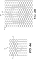
- Figure 4A depicts an array 400 of electrodes 410 that are configured, e.g. connected to a measurement circuit, to form a sensor 430, according to the present disclosure.
- a single hexagonal electrode 410 that is labeled with a "1" forms a center electrode and a ring of electrodes 410 that are marked with a "2" are interconnected to form a ring electrode.
- electrodes 410 between the center and ring electrode are electrically "floating.”
- electrodes 410 between the center and ring electrode are grounded or connected to a floating ground.
- electrodes 410 that are outside the ring electrode are electrically "floating.”
- electrodes 410 that are outside the virtual ring electrode are grounded or connected to a floating ground.
- Figure 4B depicts an alternate aspect where an array 400 of electrodes 410 has been configured to form a virtual sensor 440, according to the present disclosure.
- multiple electrodes 410 indicated by a "1," are interconnected to form a center electrode while a double-wide ring of electrodes, indicated by a "2," are interconnected to form a ring electrode.
- various numbers and positions of electrodes 410 are interconnected to form virtual electrodes of a variety of sizes and shapes.
- Figure 5A depicts an example wound, in this case a 3 rd -degree burn 500 with an open wound 510.
- Response of tissue around a 3 rd -degree burn injury may comprise three zones.
- innermost zone 520 at the center of a wound will have necrosis with no perfusion of oxygen and irreversible damage due to the coagulation of proteins.
- second zone 530 also known as the "zone of stasis," is a ring around a first zone 520, where there is a decrease in perfusion and a reduction in SEM.
- capillaries may be nonfunctional in second zone 530, leading to increased permeability of capillaries and arterioles and subsequent ischemia reperfusion injury.
- second zone 530 there may be a chance of tissue recovery in second zone 530 if cascading release of free radicals and cellular damage leading to apoptosis can be prevented.
- a zone 540 of hyperaemia where the tissue is damaged but retains good perfusion and will generally heal.
- the size, shape, and depth of wound 510 as well as zones 520, 530, 540 depends on the details of the event that caused the injury.
- evaluation of burn depth and extent is one component on which treatment decisions are based, as inaccuracies can lead to unnecessary surgeries or patients staying for extensive lengths of time.
- Figure 5B is a cross-section of a burn 500 shown in Figure 5A , taken along line A-A in Figure 5A .
- a first region 520 may extend below an open wound 510 as well as to the sides.
- a region 530 may extend below one or both of an open wound 510 and region 520.
- tissue 540 at some distance from open wound 510, there will be undamaged, or "normal,” tissue 540.
- burns may be characterized as "partial thickness” or “full thickness” burns, depending upon whether damaged zones 530 and 540 extend through a skin into subcutaneous tissue.
- Superficial partial-thickness injuries such as a blister of a 2nd-degree burn, are viable and will generally heal with antimicrobial dressings.
- Deep partial-thickness wounds are more like full-thickness burns and may require surgical excision and grafting for improved functional and cosmetic outcomes. Partial-thickness wounds are complicated to treat, as it is difficult to determine if viable structures are present and capable of healing the wound. Whatever inaccuracies associated with diagnosis may affect treatment, as it is possible that a superficial burn will receive surgery for a healing wound.
- zone 520 Burn wounds are challenging problems as they are dynamic and have the capacity to change and progress over time.
- heating of the tissue has caused complete necrosis of the dermis and all dermal structures along with fat necrosis.
- moisture content of zone 520 is lower than normal and remains low after the injury due to destruction of the local blood vessels, which prevents perfusion into the necrotic region.
- zone 530 return of blood flow after the initial thermal exposure restores perfusion and oxygenation. While not being limited to theory, the restoration of oxygenation can be important for cellular survival but also initiates a cascade of events that results in production of free radicals that lead to further tissue injury.
- the accumulation of burn edema can occur in a two-phase pattern. In the first phase, there is a rapid increase in interstitial fluid within the first hour post-injury and approximately 80% of total edema is present at 4 hours post-injury. The second phase is marked by a gradual increase in fluid accumulation over the next 12-24 hours.
- fluid movement from the capillary to the interstitium may be generally balanced by lymphatic clearance so that excess fluid does not accumulate.
- the movement of fluid and protein into the extravascular space can occur very rapidly and edema ensues because the lymphatics are unable to keep pace with the clearance of fluid and protein.
- the amount of edema in zone 540 is less than in zone 530, although the amount of SEM is still increased above normal. Mapping the pattern of edema allows an assessment of which tissue is at risk.
- Figure 6 depicts an example plot 600 of how SEM values may vary across burn 500, according to the present disclosure.
- SEM values taken along cross-section A-A have been plotted as curve 610, with the x-axis being the location along cross-section A-A and the y-axis being the SEM value.
- a reference line 612 indicates normal tissue SEM value, which may a standard reference value or a measurement of known undamaged tissue on the patient.
- curve 610 generally shows a region 620 where a SEM value is greater than reference line 612.
- curve 610 in region 620 may be only slightly raised, as indicated by the bottom of the shaded region, or may be significantly increased as indicated by the top of the shaded region 620.
- a peak value 622 of region 620 is an indication of the degree or depth of the damage in zone 530.
- point 630 on curve 610 indicates a transition from zone 530 to zone 540.
- a SEM value is higher than reference line 612 but not so elevated as to indicate a risk that a tissue will not recover.
- location of a transition from zone 530 to zone 540 may be identified on curve 610 as the x-axis position of a point 630 using a known magnitude of a SEM value.
- the magnitude of a SEM value at point 630 may be a value selected from the group consisting of a predetermined value, a predetermined increase above a reference SEM value, a percentage of a reference SEM value, a percentage of peak value 622, and other value determined from curve 610.
- a predetermined SEM value may range from 0.1 to 8.0, such as from 0.1 to 1.0, from 1.1 to 2.0, from 2.1 to 3.0, from 3.1 to 4.0, from 4.1 to 5.0, from 5.1 to 6.0, from 6.1 to 7.0, from 7.1 to 8.0, from 0.1 to 7.5, from 0.5 to 8.0, from 1.0 to 7.0, from 1.5 to 6.5, from 2.0 to 6.0, from 3.0 to 5.5, from 3.5 to 5.0, or from 4.0 to 4.5.
- a predetermined SEM value may range from 0.1 to 4.0, such as from 0.5 to 4.0, from 0.1 to 3.5, from 1.0 to 3.5, from 1.5 to 4.0, from 1.5 to 3.5, from 2.0 to 4.0, from 2.5 to 3.5, from 2.0 to 3.0, from 2.0 to 2.5, or from 2.5 to 3.0.
- a predetermined SEM value may range from 4.1 to 8.0, such as from 4.5 to 8.0, from 4.1 to 7.5, from 5.0 to 7.5, from 5.5 to 7.0, from 5.5 to 7.5, from 6.0 to 8.0, from 6.5 to 7.5, from 6.0 to 7.0, from 6.0 to 6.5, or from 6.5 to 7.0.
- a predetermined SEM value may be about 0.3, 0.35, 0.4, 0.45, 0.5, 0.55, 0.6, 0.65, 0.7, 0.75, 0.8, 0.85, 0.9, 0.95, 1.0, 1.1, 1.2, 1.3, 1.4, 1.5, 1.6, 1.7, 1.8, 1.9, 2.0, 2.1, 2.2, 2.3, 2.4, 2.5, 2.6, 2.7, 2.8, 2.9, 3.0, 3.1, 3.2, 3.3, 3.4, 3.5, 3.6, 3.7, 3.8, 3.9, 4.0, 4.1, 4.2, 4.3, 4.4, 4.5, 4.6, 4.7, 4.8, 4.9, 5.0, 5.1, 5.2, 5.3, 5.4, 5.5, 5.6, 5.7, 5.8, 5.9, 6.0, 6.1, 6.2, 6.3, 6.4, 6.5, 6.6, 6.7, 6.8, 6.9, 7.0, 7.1, 7.2, 7.3, 7.4, or 7.5.
- a predetermined SEM value
- a predetermined increase may range from 0.1 to 8.0, such as from 0.1 to 1.0, from 1.1 to 2.0, from 2.1 to 3.0, from 3.1 to 4.0, from 4.1 to 5.0, from 5.1 to 6.0, from 6.1 to 7.0, from 7.1 to 8.0, from 0.1 to 7.5, from 0.5 to 8.0, from 1.0 to 7.0, from 1.5 to 6.5, from 2.0 to 6.0, from 3.0 to 5.5, from 3.5 to 5.0, or from 4.0 to 4.5.
- a predetermined increase may range from 0.1 to 4.0, such as from 0.5 to 4.0, from 0.1 to 3.5, from 1.0 to 3.5, from 1.5 to 4.0, from 1.5 to 3.5, from 2.0 to 4.0, from 2.5 to 3.5, from 2.0 to 3.0, from 2.0 to 2.5, or from 2.5 to 3.0.
- a predetermined increase may range from 4.1 to 8.0, such as from 4.5 to 8.0, from 4.1 to 7.5, from 5.0 to 7.5, from 5.5 to 7.0, from 5.5 to 7.5, from 6.0 to 8.0, from 6.5 to 7.5, from 6.0 to 7.0, from 6.0 to 6.5, or from 6.5 to 7.0.
- a predetermined increase may be about 0.3, 0.35, 0.4, 0.45, 0.5, 0.55, 0.6, 0.65, 0.7, 0.75, 0.8, 0.85, 0.9, 0.95, 1.0, 1.1, 1.2, 1.3, 1.4, 1.5, 1.6, 1.7, 1.8, 1.9, 2.0, 2.1, 2.2, 2.3, 2.4, 2.5, 2.6, 2.7, 2.8, 2.9, 3.0, 3.1, 3.2, 3.3, 3.4, 3.5, 3.6, 3.7, 3.8, 3.9, 4.0, 4.1, 4.2, 4.3, 4.4, 4.5, 4.6, 4.7, 4.8, 4.9, 5.0, 5.1, 5.2, 5.3, 5.4, 5.5, 5.6, 5.7, 5.8, 5.9, 6.0, 6.1, 6.2, 6.3, 6.4, 6.5, 6.6, 6.7, 6.8, 6.9, 7.0, 7.1, 7.2, 7.3, 7.4, or 7.5.
- a predetermined increase may be about
- a reference SEM value is represented by a reference line 612.
- a reference SEM value may range from 0.1 to 8.0, such as from 0.1 to 1.0, from 1.1 to 2.0, from 2.1 to 3.0, from 3.1 to 4.0, from 4.1 to 5.0, from 5.1 to 6.0, from 6.1 to 7.0, from 7.1 to 8.0, from 0.1 to 7.5, from 0.5 to 8.0, from 1.0 to 7.0, from 1.5 to 6.5, from 2.0 to 6.0, from 3.0 to 5.5, from 3.5 to 5.0, or from 4.0 to 4.5.
- a reference SEM value may range from 0.1 to 4.0, such as from 0.5 to 4.0, from 0.1 to 3.5, from 1.0 to 3.5, from 1.5 to 4.0, from 1.5 to 3.5, from 2.0 to 4.0, from 2.5 to 3.5, from 2.0 to 3.0, from 2.0 to 2.5, or from 2.5 to 3.0.
- a reference SEM value may range from 4.1 to 8.0, such as from 4.5 to 8.0, from 4.1 to 7.5, from 5.0 to 7.5, from 5.5 to 7.0, from 5.5 to 7.5, from 6.0 to 8.0, from 6.5 to 7.5, from 6.0 to 7.0, from 6.0 to 6.5, or from 6.5 to 7.0.
- a reference SEM value may be about 0.3, 0.35, 0.4, 0.45, 0.5, 0.55, 0.6, 0.65, 0.7, 0.75, 0.8, 0.85, 0.9, 0.95, 1.0, 1.1, 1.2, 1.3, 1.4, 1.5, 1.6, 1.7, 1.8, 1.9, 2.0, 2.1, 2.2, 2.3, 2.4, 2.5, 2.6, 2.7, 2.8, 2.9, 3.0, 3.1, 3.2, 3.3, 3.4, 3.5, 3.6, 3.7, 3.8, 3.9, 4.0, 4.1, 4.2, 4.3, 4.4, 4.5, 4.6, 4.7, 4.8, 4.9, 5.0, 5.1, 5.2, 5.3, 5.4, 5.5, 5.6, 5.7, 5.8, 5.9, 6.0, 6.1, 6.2, 6.3, 6.4, 6.5, 6.6, 6.7, 6.8, 6.9, 7.0, 7.1, 7.2, 7.3, 7.4, or 7.5.
- a reference SEM value may be
- a peak value may range from 0.1 to 8.0, such as from 0.1 to 1.0, from 1.1 to 2.0, from 2.1 to 3.0, from 3.1 to 4.0, from 4.1 to 5.0, from 5.1 to 6.0, from 6.1 to 7.0, from 7.1 to 8.0, from 0.1 to 7.5, from 0.5 to 8.0, from 1.0 to 7.0, from 1.5 to 6.5, from 2.0 to 6.0, from 3.0 to 5.5, from 3.5 to 5.0, or from 4.0 to 4.5.
- a peak value may range from 0.1 to 4.0, such as from 0.5 to 4.0, from 0.1 to 3.5, from 1.0 to 3.5, from 1.5 to 4.0, from 1.5 to 3.5, from 2.0 to 4.0, from 2.5 to 3.5, from 2.0 to 3.0, from 2.0 to 2.5, or from 2.5 to 3.0.
- a peak value may range from 4.1 to 8.0, such as from 4.5 to 8.0, from 4.1 to 7.5, from 5.0 to 7.5, from 5.5 to 7.0, from 5.5 to 7.5, from 6.0 to 8.0, from 6.5 to 7.5, from 6.0 to 7.0, from 6.0 to 6.5, or from 6.5 to 7.0.
- a peak value may be about 0.3, 0.35, 0.4, 0.45, 0.5, 0.55, 0.6, 0.65, 0.7, 0.75, 0.8, 0.85, 0.9, 0.95, 1.0, 1.1, 1.2, 1.3, 1.4, 1.5, 1.6, 1.7, 1.8, 1.9, 2.0, 2.1, 2.2, 2.3, 2.4, 2.5, 2.6, 2.7, 2.8, 2.9, 3.0, 3.1, 3.2, 3.3, 3.4, 3.5, 3.6, 3.7, 3.8, 3.9, 4.0, 4.1, 4.2, 4.3, 4.4, 4.5, 4.6, 4.7, 4.8, 4.9, 5.0, 5.1, 5.2, 5.3, 5.4, 5.5, 5.6, 5.7, 5.8, 5.9, 6.0, 6.1, 6.2, 6.3, 6.4, 6.5, 6.6, 6.7, 6.8, 6.9, 7.0, 7.1, 7.2, 7.3, 7.4, or 7.5.
- a peak value can be about 0.3,
- One or more regions may be defined on a body. In an aspect, measurements made within a region are considered comparable to each other.
- a region may be defined as an area on the skin of the body where measurements may be taken at any point within the area.
- a region corresponds to an anatomical region (e.g., heel, ankle, lower back).
- a region may be defined as a set of two or more specific points relative to anatomical features where measurements are taken only at the specific points.
- a region may comprise a plurality of non-contiguous areas on the body.
- the set of specific locations may include points in multiple non-contiguous areas.
- a region is defined by surface area.
- a region may be, for example, between 5 and 200 cm 2 , between 5 and 100 cm 2 , between 5 and 50 cm 2 , or between 10 and 50 cm 2 , between 10 and 25 cm 2 , or between 5 and 25 cm 2 .
- measurements may be made in a specific pattern or portion thereof.
- the pattern of readings is made in a pattern with the target area of concern in the center.
- measurements are made in one or more circular patterns of increasing or decreasing size, T-shaped patterns, a set of specific locations, or randomly across a tissue or region.
- a pattern may be located on the body by defining a first measurement location of the pattern with respect to an anatomical feature with the remaining measurement locations of the pattern defined as offsets from the first measurement position.
- a plurality of measurements are taken across a tissue or region and the difference between the lowest measurement value and the highest measurement value of the plurality of measurements is recorded as a delta value of that plurality of measurements.
- 3 or more, 4 or more, 5 or more, 6 or more, 7 or more, 8 or more, 9 or more, or 10 or more measurements are taken across a tissue or region.
- a threshold may be established for at least one region.
- a threshold of 0.2, 0.3, 0.4, 0.5, 0.6, 0.7, 0.8, 0.9, or other value may be established for the at least one region.
- a delta value is identified as significant when the delta value of a plurality of measurements taken within a region meets or exceeds a threshold associated with that region.
- each of a plurality of regions has a different threshold.
- two or more regions may have a common threshold.
- a threshold has both a delta value component and a chronological component, where a delta value is identified as significant when the delta value is greater than a predetermined numerical value for a predetermined portion of a time interval.
- the predetermined portion of a time interval is defined as a minimum of X days where a plurality of measurements taken that day produces a delta value greater than or equal to the predetermined numerical value within a total of Y contiguous days of measurement.
- the predetermined portion of a time interval may be defined as 1, 2, 3, 4, or 5 consecutive days on which a plurality of measurements taken that day produces a delta value that is greater than or equal to the predetermined numerical value.
- the predetermined portion of a time interval may be defined as some portion of a different specific time period (weeks, month, hours etc.).
- a threshold has a trending aspect where changes in the delta values of consecutive pluralities of measurements are compared to each other.
- a trending threshold is defined as a predetermined change in delta value over a predetermined length of time, where a determination that the threshold has been met or exceeded is significant. In an aspect, a determination of significance will cause an alert to be issued.
- a trend line may be computed from a portion of the individual measurements of the consecutive pluralities of measurements. In an aspect, a trend line may be computed from a portion of the delta values of the consecutive pluralities of measurements.
- the number of measurements taken within a single region may be less than the number of measurement locations defined in a pattern.
- a delta value will be calculated after a predetermined initial number of readings, which is less than the number of measurement locations defined in a pattern, have been taken in a region and after each additional reading in the same region, where additional readings are not taken once the delta value meets or exceeds the threshold associated with that region.
- the number of measurements taken within a single region may exceed the number of measurement locations defined in a pattern.
- a delta value will be calculated after each additional reading.
- a quality metric may be generated for each plurality of measurements. In an aspect, this quality metric is chosen to assess the repeatability of the measurements. In an aspect, this quality metric is chosen to assess the skill of the clinician that took the measurements. In an aspect, the quality metric may include one or more statistical parameters, for example an average, a mean, or a standard deviation. In an aspect, the quality metric may include one or more of a comparison of individual measurements to a predefined range. In an aspect, the quality metric may include comparison of the individual measurements to a pattern of values, for example comparison of the measurement values at predefined locations to ranges associated with each predefined location. In an aspect, the quality metric may include determination of which measurements are made over healthy tissue and one or more evaluations of consistency within this subset of "healthy" measurements, for example a range, a standard deviation, or other parameter.
- a measurement for example, a threshold value, is determined by SEM Scanner Model 200 (Bruin Biometrics, LLC, Los Angeles, CA). In another aspect, a measurement is determined by another SEM scanner.
- a measurement value is based on a capacitance measurement by reference to a reference device.
- a capacitance measurement can depend on the location and other aspects of any electrode in a device. Such variations can be compared to a reference SEM device such as an SEM Scanner Model 200 (Bruin Biometrics, LLC, Los Angeles, CA).
- a reference SEM device such as an SEM Scanner Model 200 (Bruin Biometrics, LLC, Los Angeles, CA).
- a percentage in accordance with the present disclosure may range from 0-100%, such as 0-50%, 25-75%, 50-100%, 0-10%, 5-15%, 10-20%, 15-25%, 20-30%, 25-35%, 30-40%, 35%-45%, 40-50%, 0-25%, 15-35%, 25-50%, 45-55%, 50-60%, 55-65%, 60-70%, 65-75%, 40-55%, 50-75%, 70-80%, 75%-85%, 80-90%, 85-95%, 90-100%, 65-85%, or 75-100%.
- a percentage in accordance with the present disclosure may be about 0%, 1%, 2%, 3%, 4%, 5%, 6%, 7%, 8%, 9%, 10%, 15%, 20%, 25%, 30%, 35%, 40%, 45%, 50%, 55%, 60%, 65%, 70%, 75%, 80%, 85%, 90%, 95%, or 100%.
- point 640 on curve 610 indicates a transition from zone 530, where edema has occurred, to zone 520, where the tissue has a moisture content below normal.
- a measured SEM value that equals the normal value of reference line 612 indicates that a portion of a sensor is over tissue having a higher-than-normal moisture content while the remaining portion of the sensor is over tissue having a lower-than-normal moisture content.
- point 640 on line A-A is approximately the location of the edge of zone 520. If it is desirable to excise the necrotic tissue from a patient, marking the skin at this point provides a reference to the surgeon of the edge of necrotic tissue.
- successive measurements of SEM values at one or more points proximate to an open wound 510 can provide information regarding the degree of damage to the tissue.
- successive measurements can be performed at approximately 5 minute intervals, 10 minute intervals, 15 minute intervals, 20 minute intervals, 25 minute intervals, 35 minute intervals, 40 minute intervals, 45 minute intervals, 50 minute intervals, 60 minute intervals, 90 minute intervals, or 120 minute intervals.
- successive measurement can be performed at time intervals for the first 1 hour, 2 hours, 3 hours, 5 hours, 6 hours, 7 hours, 8 hours, 9 hours, 10 hours, 11 hours, or 12 hours after an injury.
- the value and position of point 622 over the first 4 hours post-injury may indicate the depth of the burn and the risk of tissue depth in certain areas.
- Outward progression of the peak SEM values on the x-axis may indicate the severity of the reperfusion damage.
- measurements of SEM values may be taken with a single-sensor device, such as a SEM scanner 170 of Figure 1B , and logged, plotted, and assessed.
- the methods (not forming part of the claims) and apparatus disclosed herein may also be used to track the healing process of injuries such as burns, cuts, ulcers, and other types of tissue damage. Closure of the skin over a wound is not the end of the healing process, and it may take a year after the skin closes for the sub-epidermal tissue to return to its original state. Periodic assessment of the site of the original wound will show whether the healing is continuing to progress or has halted or reversed. As an example, pressure ulcers are known to suffer a high incidence of recurrence at the same location as a first ulcer. This is thought to be a result of continued pressure at the site combined with a weakened tissue structure as a result of incomplete healing.
- an electro-stimulus device may be used once a wound has closed in order to accelerate the healing process of the underlying tissue. The progress of the healing is likely to be difficult if not impossible to assess manually or visually.
- a SEM scanning device could be used to establish one or more of a SEM measurement at the site of the closed wound, periodic measurements and trend analysis to verify the effectiveness of the healing device, and measurement of adjacent tissue as a reference of fully healed tissue.
- adjustments may be made to the healing device, for example a change in the frequency or voltage of an electro-stimulus device, based on the measurements or the trend of the measurements made by an SEM scanner.
- the use of a healing device or therapy may be halted or replaced with a different device or therapy based on the SEM measurements or trend.
- the wound may be judged to be "healed” based on the SEM measurement and healing therapies may be halted, modified, or replaced with preventative therapies.
- the difference between a current SEM reading at the site of the wound and a reference value from nearby healthy tissue is a metric of the degree of recovery of the tissue at the wound site, where a zero difference is fully healed and restored to original condition.
- Figure 7 depicts an aspect of a SEM sensing apparatus 700, according to the present disclosure.
- a flexible substrate 710 has a plurality of SEM sensors 720 arranged on a common surface of substrate 710.
- sensors 720 comprise toroidal sensors 90 as shown in Figure 1A .
- sensors 720 comprise an electrode array 290 as shown in Figure 2 .
- sensors 720 comprise an electrode array 400 as shown in Figure 3 .
- sensors 720 are coupled to electronics (not shown in Figure 7 ) that provide excitation and measure an SEM value of the tissue below the respective sensors 720.
- SEM sensing apparatus 700 comprises visual indicators 730 that are arranged on a substrate 710.
- visual indicators 730 are on a first surface of a substrate 710 while sensors 720 are on a second surface of substrate 710 that is opposite the first surface.
- visual indicators 730 are disposed between at least some pairs of sensors 720.
- visual indicators 730 may be light emitting devices (LEDs).
- visual indicators 730 may emit a single color of light.
- visual indicators 730 may selectably emit one of a plurality of colors of light.
- visual indicators 730 are selectable to be on or off.
- visual indicators 730 are coupled to electronics (not shown in Figure 7 ) that provide excitation and selectable control of visual indicators 730.
- electronics of the present disclosure actuate each visual indicator 730 with a color of light selected based on the SEM values measured by sensors 90 disposed on each side of the respective visual indicator 730. This provides a color-coded map of the various zones 520, 530, and 540 for a given wound 500.
- visual indicators 730 may be disposed on the same surface of substrate 710 as sensors 720.
- visual indicators 730 comprise marking element (not visible in Figure 7 ) that can selectably mark the skin of a patient on which a SEM sensing apparatus 700 is placed.
- electronics of the present disclosure can actuate the marking element of visual indicators 720 that are disposed along one or more of the boundaries between zones of Figures 5A and 5B .
- electronics of the present disclosure may actuate the marking elements to mark the boundary between zone 520 and zone 530, indicating the outer edge of non-viable tissue.
- Figures 8A and 8B disclose an aspect of a SEM sensing assembly 702, according to the present disclosure.
- an array 740 of electrodes 742 is disposed on a substrate 712.
- electrodes 742 are similar to electrodes 300 of Figure 2 .
- electrodes 742 are similar to electrodes 410 of Figure 3 .
- a SEM sensing apparatus 702 comprises a plurality of perforations 750.
- perforations 750 are disposed between pairs of electrodes 742, as shown in Figure 8B .
- SEM sensing apparatus 702 can be placed on the skin of a patient over a wound and a clinician marks the skin of the patient as guided by the SEM values measured between various pairs of electrodes 742.
- a SEM sensing apparatus 700 may comprise both visual indicators 730 and perforations 750, allowing a clinician to mark the skin of a patient as guided by the colors of various visual indicators 730.
- Figure 9 discloses an aspect of an apparatus 800 for mapping areas of damage around a wound, according to the present disclosure.
- a patient's arm 20 has a burn 501 with an open wound 511.
- apparatus 800 comprises an instrument head 810 overhanging arm 20 with an optical system 815 that comprises a camera (not visible in Figure 9 ) that observes area 825 on arm 20 and a projector (not visible in Figure 9 ) that can project one or more images onto area 825, which encompasses wound 511 as well as tissue around wound 511.
- a SEM sensing apparatus 840 is coupled to electronics (not shown in Figure 9 ) that also control optical system 815.
- SEM sensing apparatus 840 is coupled to electronics of the present disclosure through a cable 845.
- SEM sensing apparatus 840 comprises a wireless linkage in place of cable 845.
- SEM sensing apparatus 840 comprises a fiducial 850 that is visible to a camera while apparatus 800 is in use.
- SEM sensing apparatus 840 comprises a single bioimpedance sensor and, therefore, measures the ECF at a single point at a time.
- a user can make multiple measurements with a SEM sensing apparatus 840 in area 825.
- a camera can observe and record the position of fiducial 850 in its field of view.
- reference marks may be made on arm 20 to record the position of arm 20 in the field of view and enable movement of arm 20 during an assessment.
- electronics of the present disclosure determines the location of a boundary between tissue types, for example a boundary between viable and non-viable tissue, and causes the projector to project indicating images along this boundary. In Figure 9 , these images are shown as dots 710.
- a projected image may comprise lines, areas of color, areas shading from a first color to a second color, areas shading from one intensity of a color to a different intensity of the same color, or other visual indication that provides guidance as to the condition of the tissue in area 825.
- electronics of the present disclosure may be coupled to a printer (not shown in Figure 9 ) and can cause the printer to produce a picture of arm 20 with wound 511 taken by a camera and overlaid with markings equivalent to those described as provided by a projector.
- measurements may be repeated with SEM sensing apparatus 800 and new pictures printed, thereby creating a pictorial history of the progression of damage around a wound.
- electronics of the present disclosure may be coupled to a storage device, for example a server, and configured to store information regarding an image of arm 20 and wound 511 as well as measurements and locations of the measurements made by a SEM sensing apparatus 840 at one or more times.
Landscapes
- Health & Medical Sciences (AREA)
- Life Sciences & Earth Sciences (AREA)
- Physics & Mathematics (AREA)
- Molecular Biology (AREA)
- Animal Behavior & Ethology (AREA)
- Veterinary Medicine (AREA)
- Biophysics (AREA)
- Pathology (AREA)
- Engineering & Computer Science (AREA)
- Biomedical Technology (AREA)
- Heart & Thoracic Surgery (AREA)
- Medical Informatics (AREA)
- Public Health (AREA)
- Surgery (AREA)
- General Health & Medical Sciences (AREA)
- Dermatology (AREA)
- Radiology & Medical Imaging (AREA)
- Nuclear Medicine, Radiotherapy & Molecular Imaging (AREA)
- General Physics & Mathematics (AREA)
- Investigating Or Analysing Biological Materials (AREA)
- Investigating Or Analyzing Materials By The Use Of Electric Means (AREA)
- Measurement And Recording Of Electrical Phenomena And Electrical Characteristics Of The Living Body (AREA)
- Measuring And Recording Apparatus For Diagnosis (AREA)
- Measuring Or Testing Involving Enzymes Or Micro-Organisms (AREA)
- Medicines That Contain Protein Lipid Enzymes And Other Medicines (AREA)
- Apparatus Associated With Microorganisms And Enzymes (AREA)
Description
- This application claims the benefit of priority of
U.S. Provisional Application 62/454,487 filed February 3, 2017 U.S. Provisional Application 62/521,926 filed June 19, 2017 - The present disclosure provides apparatus and methods (with no methods forming part of the claims) for measuring type and degree of tissue damage around a burn or other type of wound.
- Serious wounds and burns may have regions of various degrees of damage surrounding the wound site. Effective treatment may require removal of non-viable tissue, yet it can be difficult to visually assess tissue viability. For an open wound such as a burn, there may be a region of non-viable tissue around the immediate wound while further away the tissue may be less damaged and characterized by swelling known as "edema" yet viable and likely to recover.
- A common method of burn evaluation assesses the visual and tactile characteristics, namely wound appearance, capillary blanching and refill, capillary staining, and burn wound sensibility to light touch and pinprick. Estimation of the burn depth is difficult. In addition, burn wounds are dynamic and can progress over time and the changes do not immediately become visually apparent.
WO 2009/144615 A1 relates to a device for electrical treatment of a skin wound comprising a flexible substrate adapted for attaching to the skin wound and the surrounding skin, a matrix of electrodes, means for determining the presence of the wound and/or its perimeter and/or means for controlling a liquid load between the matrix and the wound, and means for applying a voltage between the wound and the surrounding skin.EP 3 092 946 A1EP 3 092 946 A1 - The invention relates to an apparatus for mapping regions of damage around a wound as defined in claim 1. Preferred embodiments of the invention are set out in the dependent claims.
- Some aspects of the disclosure are herein described, by way of example only, with reference to the accompanying drawings. With specific reference now to the drawings in detail, it is stressed that the particulars shown are by way of example and are for purposes of illustrative discussion of aspects of the disclosure. In this regard, the description and the drawings, considered alone and together, make apparent to those skilled in the art how aspects of the disclosure may be practiced.
-
Figure 1A discloses a toroidal bioimpedance sensor. -
Figure 1B discloses an idealized field map created by the toroidal sensor ofFigure 1A when activated. -
Figure 1C discloses a SEM scanner that comprises the sensor ofFigure 1A . -
Figure 2 is a first exemplary array of electrodes. -
Figure 3 is an exemplary array of electrodes according to the present disclosure. -
Figure 4A illustrates a first example of how the array of electrodes disclosed inFigure 3 is configured to form a bioimpedance sensor according to the present disclosure. -
Figure 4B illustrates a second example of how the array of electrodes disclosed inFigure 3 is configured to form a bioimpedance sensor according to the present disclosure. -
Figure 5A depicts an example 3rd-degree burn with an open wound. -
Figure 5B depicts a cross-section of the wound ofFigure 5A . -
Figure 6 provides anexample plot 600 of how SEM values may vary across the wound ofFigure 5A , according to the present disclosure. -
Figure 7 discloses a first exemplary aspect of an SEM sensing apparatus according to the present disclosure. -
Figure 8A discloses a second exemplary aspect of an SEM sensing apparatus according to the present disclosure. -
Figure 8B discloses a third exemplary aspect of an SEM sensing apparatus according to the present disclosure. -
Figure 9 discloses an aspect of an apparatus for mapping areas of damage according to the present disclosure. - The present disclosure describes measurement of various electrical characteristics and derivation of SEM values indicative of the accumulation or depletion of extracellular fluid (ECF), also referred to as intercellular fluid, and the application of this information to the assessment of tissue viability. Examples are provided of application to thermal burns yet are applicable to other types of wounds. These examples are not limiting and the demonstrated principles may be applied to a larger scope of injuries and conditions than the specific example. For example, apparatus and methods disclosed in relation to a 3rd-degree burn may be used with equal efficacy to an open cut, gangrene, an ulcer, or other similar injury.
- Assessment of tissue viability around wounds and burns may be improved by determination of the amount of SEM in the tissue surrounding the actual damage. Typically, the tissue immediately around a wound will exhibit a reduced level of SEM, indicating a lower level of tissue viability. Further out from the wound, the tissue will exhibit an increased level of moisture, or edema. This value may be very high around the edge of the low-moisture tissue, indicating a high degree of damage with a high risk of eventual tissue death. The SEM value may taper off with increasing distance from the wound, where a moderately raised SEM level indicates damage with a higher chance of tissue viability. Mapping the areas of low-viability tissue, as indicated by reduced levels of tissue moisture, and the surrounding area of edema can provide important guidance to a clinician during the treatment of the wound.
- This description is not intended to be a detailed catalog of all the different ways in which the disclosure may be implemented, or all the features that may be added to the instant disclosure. Hence, the following descriptions are intended to illustrate some particular embodiments of the disclosure, and not to exhaustively specify all permutations, combinations and variations thereof.
- Unless otherwise defined, all technical and scientific terms used herein have the same meaning as commonly understood by one of ordinary skill in the art to which this disclosure belongs. The terminology used in the description of the disclosure herein is for the purpose of describing particular embodiments or aspects only and is not intended to be limiting of the disclosure.
-
U.S. Patent Applications 14/827,375 and15/134,110 - The methods (not forming part of the claims) disclosed herein comprise one or more steps or actions for achieving the described method. The method steps and/or actions may be interchanged with one another without departing from the scope of the present invention. In other words, unless a specific order of steps or actions is required for proper operation of the embodiment, the order and/or use of specific steps and/or actions may be modified.
- As used in the description of the disclosure and the appended claims, the singular forms "a," "an" and "the" are intended to include the plural forms as well, unless the context clearly indicates otherwise.
- As used herein, "and/or" refers to and encompasses any and all possible combinations of one or more of the associated listed items, as well as the lack of combinations when interpreted in the alternative ("or").
- The terms "about" and "approximately" as used herein when referring to a measurable value such as a length, a frequency, or a SEM value and the like, is meant to encompass variations of ± 20%, ± 10%, ± 5%, ± 1%, ± 0.5%, or even ± 0.1% of the specified amount.
- As used herein, phrases such as "between X and Y" and "between about X and Y" should be interpreted to include X and Y. As used herein, phrases such as "between about X and Y" mean "between about X and about Y" and phrases such as "from about X to Y" mean "from about X to about Y."
- The terms "comprise," "comprises," and "comprising" as used herein, specify the presence of the stated features, integers, steps, operations, elements, and/or components, but do not preclude the presence or addition of one or more other features, integers, steps, operations, elements, components, and/or groups thereof.
- As used herein, the term "sub-epidermal moisture" or "SEM" refers to the increase in tissue fluid and local edema caused by vascular leakiness and other changes that modify the underlying structure of the damaged tissue in the presence of continued pressure on tissue, apoptosis, necrosis, and the inflammatory process.
- As used herein, a "system" may be a collection of devices in wired or wireless communication with each other.
- As used herein, "interrogate" refers to the use of radiofrequency energy to penetrate into a patient's skin.
- As used herein, a "patient" may be a human or animal subject.
- As used herein, a "3rd-degree burn" refers to a full thickness burn that goes through the dermis and affect deeper tissues.
-
Figure 1A discloses atoroidal bioimpedance sensor 90. In this exemplary configuration, acenter electrode 110 is surrounded by aring electrode 120. Without being limited to a particular theory, a gap between two electrodes ofsensor 90 can affect the depth of field penetration into a substrate belowsensor 90. In an aspect, a ground plane (not visible inFigure 1A ), is parallel to and separate from the plane of the electrodes. In one aspect, a ground plan extends beyond the outer diameter ofring electrode 120. Without being limited to a particular theory, a ground plane can limit the field betweenelectrodes electrodes electrodes -
Figure 1B discloses an idealized field map created by a toroidal sensor ofFigure 1A when activated by a drive circuit (not shown inFigure 1B ). In one aspect, when an electric voltage is applied across twoelectrodes electric field 140 is generated betweenelectrodes electrodes field 150. In an aspect, the diameter of acenter electrode 110, the inner and outer diameters of aring electrode 120, and the gap between twoelectrodes field 140, for example the depth offield 150. - In use, a drive circuit can measure an electrical property or parameter that comprises one or more of a resistance, a capacitance, an inductance, an impedance, a reluctance, or other electrical characteristic as sensed by
electric field 140. Depending on the type of drive circuit being employed in an apparatus, a sensor of an apparatus may be a bipolar radiofrequency sensor, a bioimpedance sensor, a capacitive sensor, or an SEM sensor. In an aspect, the measured electrical parameter is related to the moisture content of the epidermis of a patient at a depth that is determined by the geometry ofelectrodes electrical field 140, and other operating characteristics of an apparatus drive circuit. In one aspect, the measured moisture content is equivalent to the SEM content with a value on a predetermined scale. In an aspect, a predetermined scale may range from 0 to 20, such as from 0 to 1, from 0 to 2, from 0 to 3, from 0 to 4, from 0 to 5, from 0 to 6, from 0 to 7, from 0 to 8, from 0 to 9, from 0 to 10, from 0 to 11, from 0 to 12, from 0 to 13, from 0 to 14, from 0 to 15, from 0 to 16, from 0 to 17, from 0 to 18, from 0 to 19. In one aspect, a predetermined scaled can be scaled by a factor or a multiple based on the values provided herein. -
Figure 1C provides top and bottom views of aSEM scanner 170 that comprises electronics that drivesensor 174, which is similar tosensor 90 ofFigure 1A , and measure a capacitance betweenelectrodes display 176. - These aspects of
sensor 90 andSEM scanner 170 are disclosed inWO 2016/172263 , from which theU.S. Patent Application 15/134,110 was filed as a national phase entry. -
Figure 2 depicts anexemplary electrode array 290, according to the present disclosure. In an aspect, anarray 290 is composed ofindividual electrodes 300 disposed, in this example, in a regular pattern over asubstrate 292. In an aspect, eachelectrode 300 is separately coupled (through conductive elements not shown inFigures 2 through 4B ) to a circuit, such as described with respect toFigure 4A , that is configured to measure an electrical parameter. In one aspect, a "virtual sensor" is created by selective connection of predetermined subsets ofelectrodes 300 to a common element of a circuit. In one aspect, aparticular electrode 310 is connected as a center electrode, similar toelectrode 110 ofFigure 1A , and sixelectrodes 320A-320F are connected together as a "virtual ring" electrode, similar toelectrode 120 ofFigure 1A . In an aspect, two individual electrodes are individually connected to a circuit to form a virtual sensor, forexample electrodes more electrodes 300 are connected together to form one or the other electrodes of a two-electrode sensor. - Any pair of electrodes, whether composed of single electrodes or a set of electrodes coupled together to form virtual electrodes, is coupled to electronics that are configured to measures an electrical property or parameter that comprises one or more of a resistance, a capacitance, an inductance, an impedance, a reluctance, or other electrical characteristic with one or more of
sensors -
Figure 3 depicts anotherexemplary array 400 ofelectrodes 410, according to the present disclosure. In an aspect, each ofelectrodes 410 is an approximate hexagon that is separated from each of the surroundingelectrodes 410 by agap 420. In one aspect,electrodes 410 are one of circles, squares, pentagons, or other regular or irregular shapes. In an aspect,gap 420 is uniform between allelectrodes 410. In one aspect,gap 420 varies between various electrodes. In an aspect,electrodes 410 may be interconnected to form virtual sensors as described below with respect toFigures 5A and 5B . -
Figure 4A depicts anarray 400 ofelectrodes 410 that are configured, e.g. connected to a measurement circuit, to form asensor 430, according to the present disclosure. In an aspect, a singlehexagonal electrode 410 that is labeled with a "1" forms a center electrode and a ring ofelectrodes 410 that are marked with a "2" are interconnected to form a ring electrode. In an aspect,electrodes 410 between the center and ring electrode are electrically "floating." In one aspect,electrodes 410 between the center and ring electrode are grounded or connected to a floating ground. In one aspect,electrodes 410 that are outside the ring electrode are electrically "floating." In an aspect,electrodes 410 that are outside the virtual ring electrode are grounded or connected to a floating ground. -
Figure 4B depicts an alternate aspect where anarray 400 ofelectrodes 410 has been configured to form avirtual sensor 440, according to the present disclosure. In an aspect,multiple electrodes 410, indicated by a "1," are interconnected to form a center electrode while a double-wide ring of electrodes, indicated by a "2," are interconnected to form a ring electrode. In one aspect, various numbers and positions ofelectrodes 410 are interconnected to form virtual electrodes of a variety of sizes and shapes. -
Figure 5A depicts an example wound, in this case a 3rd-degree burn 500 with anopen wound 510. Response of tissue around a 3rd-degree burn injury may comprise three zones. In an aspect,innermost zone 520 at the center of a wound will have necrosis with no perfusion of oxygen and irreversible damage due to the coagulation of proteins. In one aspect,second zone 530, also known as the "zone of stasis," is a ring around afirst zone 520, where there is a decrease in perfusion and a reduction in SEM. Without being limited to a particular theory, capillaries may be nonfunctional insecond zone 530, leading to increased permeability of capillaries and arterioles and subsequent ischemia reperfusion injury. There may be a chance of tissue recovery insecond zone 530 if cascading release of free radicals and cellular damage leading to apoptosis can be prevented. In an aspect, surrounding asecond zone 530 is azone 540 of hyperaemia where the tissue is damaged but retains good perfusion and will generally heal. Without being limited to a particular theory, the size, shape, and depth ofwound 510 as well aszones -
Figure 5B is a cross-section of aburn 500 shown inFigure 5A , taken along line A-A inFigure 5A . In an aspect, afirst region 520 may extend below anopen wound 510 as well as to the sides. In one aspect, aregion 530 may extend below one or both of anopen wound 510 andregion 520. In an aspect, at some distance fromopen wound 510, there will be undamaged, or "normal,"tissue 540. - In accordance with the present disclosure, burns may be characterized as "partial thickness" or "full thickness" burns, depending upon whether damaged
zones - Burn wounds are challenging problems as they are dynamic and have the capacity to change and progress over time. In
zone 520, heating of the tissue has caused complete necrosis of the dermis and all dermal structures along with fat necrosis. Without being limited to a particular theory, moisture content ofzone 520 is lower than normal and remains low after the injury due to destruction of the local blood vessels, which prevents perfusion into the necrotic region. - Without being limited to a particular theory, in
zone 530, return of blood flow after the initial thermal exposure restores perfusion and oxygenation. While not being limited to theory, the restoration of oxygenation can be important for cellular survival but also initiates a cascade of events that results in production of free radicals that lead to further tissue injury. The accumulation of burn edema can occur in a two-phase pattern. In the first phase, there is a rapid increase in interstitial fluid within the first hour post-injury and approximately 80% of total edema is present at 4 hours post-injury. The second phase is marked by a gradual increase in fluid accumulation over the next 12-24 hours. In non-burn injuries, fluid movement from the capillary to the interstitium may be generally balanced by lymphatic clearance so that excess fluid does not accumulate. However, in burn injuries, while not being limited to theory, the movement of fluid and protein into the extravascular space can occur very rapidly and edema ensues because the lymphatics are unable to keep pace with the clearance of fluid and protein. Accordingly, again without being limited to a particular theory, in an aspect, the amount of edema inzone 540 is less than inzone 530, although the amount of SEM is still increased above normal. Mapping the pattern of edema allows an assessment of which tissue is at risk. -
Figure 6 depicts anexample plot 600 of how SEM values may vary acrossburn 500, according to the present disclosure. SEM values taken along cross-section A-A have been plotted ascurve 610, with the x-axis being the location along cross-section A-A and the y-axis being the SEM value. Areference line 612 indicates normal tissue SEM value, which may a standard reference value or a measurement of known undamaged tissue on the patient. - In an aspect,
curve 610 generally shows aregion 620 where a SEM value is greater thanreference line 612. In one aspect,curve 610 inregion 620 may be only slightly raised, as indicated by the bottom of the shaded region, or may be significantly increased as indicated by the top of the shadedregion 620. In an aspect, apeak value 622 ofregion 620 is an indication of the degree or depth of the damage inzone 530. - In one aspect,
point 630 oncurve 610 indicates a transition fromzone 530 tozone 540. In an aspect, a SEM value is higher thanreference line 612 but not so elevated as to indicate a risk that a tissue will not recover. In one aspect, location of a transition fromzone 530 tozone 540 may be identified oncurve 610 as the x-axis position of apoint 630 using a known magnitude of a SEM value. In an aspect, the magnitude of a SEM value atpoint 630 may be a value selected from the group consisting of a predetermined value, a predetermined increase above a reference SEM value, a percentage of a reference SEM value, a percentage ofpeak value 622, and other value determined fromcurve 610. - In an aspect, a predetermined SEM value may range from 0.1 to 8.0, such as from 0.1 to 1.0, from 1.1 to 2.0, from 2.1 to 3.0, from 3.1 to 4.0, from 4.1 to 5.0, from 5.1 to 6.0, from 6.1 to 7.0, from 7.1 to 8.0, from 0.1 to 7.5, from 0.5 to 8.0, from 1.0 to 7.0, from 1.5 to 6.5, from 2.0 to 6.0, from 3.0 to 5.5, from 3.5 to 5.0, or from 4.0 to 4.5. In an aspect, a predetermined SEM value may range from 0.1 to 4.0, such as from 0.5 to 4.0, from 0.1 to 3.5, from 1.0 to 3.5, from 1.5 to 4.0, from 1.5 to 3.5, from 2.0 to 4.0, from 2.5 to 3.5, from 2.0 to 3.0, from 2.0 to 2.5, or from 2.5 to 3.0. In one aspect, a predetermined SEM value may range from 4.1 to 8.0, such as from 4.5 to 8.0, from 4.1 to 7.5, from 5.0 to 7.5, from 5.5 to 7.0, from 5.5 to 7.5, from 6.0 to 8.0, from 6.5 to 7.5, from 6.0 to 7.0, from 6.0 to 6.5, or from 6.5 to 7.0. In one aspect, a predetermined SEM value may be about 0.3, 0.35, 0.4, 0.45, 0.5, 0.55, 0.6, 0.65, 0.7, 0.75, 0.8, 0.85, 0.9, 0.95, 1.0, 1.1, 1.2, 1.3, 1.4, 1.5, 1.6, 1.7, 1.8, 1.9, 2.0, 2.1, 2.2, 2.3, 2.4, 2.5, 2.6, 2.7, 2.8, 2.9, 3.0, 3.1, 3.2, 3.3, 3.4, 3.5, 3.6, 3.7, 3.8, 3.9, 4.0, 4.1, 4.2, 4.3, 4.4, 4.5, 4.6, 4.7, 4.8, 4.9, 5.0, 5.1, 5.2, 5.3, 5.4, 5.5, 5.6, 5.7, 5.8, 5.9, 6.0, 6.1, 6.2, 6.3, 6.4, 6.5, 6.6, 6.7, 6.8, 6.9, 7.0, 7.1, 7.2, 7.3, 7.4, or 7.5. In an aspect, a predetermined SEM value can be scaled by a factor or a multiple based on the values provided herein.
- In an aspect, a predetermined increase may range from 0.1 to 8.0, such as from 0.1 to 1.0, from 1.1 to 2.0, from 2.1 to 3.0, from 3.1 to 4.0, from 4.1 to 5.0, from 5.1 to 6.0, from 6.1 to 7.0, from 7.1 to 8.0, from 0.1 to 7.5, from 0.5 to 8.0, from 1.0 to 7.0, from 1.5 to 6.5, from 2.0 to 6.0, from 3.0 to 5.5, from 3.5 to 5.0, or from 4.0 to 4.5. In an aspect, a predetermined increase may range from 0.1 to 4.0, such as from 0.5 to 4.0, from 0.1 to 3.5, from 1.0 to 3.5, from 1.5 to 4.0, from 1.5 to 3.5, from 2.0 to 4.0, from 2.5 to 3.5, from 2.0 to 3.0, from 2.0 to 2.5, or from 2.5 to 3.0. In one aspect, a predetermined increase may range from 4.1 to 8.0, such as from 4.5 to 8.0, from 4.1 to 7.5, from 5.0 to 7.5, from 5.5 to 7.0, from 5.5 to 7.5, from 6.0 to 8.0, from 6.5 to 7.5, from 6.0 to 7.0, from 6.0 to 6.5, or from 6.5 to 7.0. In one aspect, a predetermined increase may be about 0.3, 0.35, 0.4, 0.45, 0.5, 0.55, 0.6, 0.65, 0.7, 0.75, 0.8, 0.85, 0.9, 0.95, 1.0, 1.1, 1.2, 1.3, 1.4, 1.5, 1.6, 1.7, 1.8, 1.9, 2.0, 2.1, 2.2, 2.3, 2.4, 2.5, 2.6, 2.7, 2.8, 2.9, 3.0, 3.1, 3.2, 3.3, 3.4, 3.5, 3.6, 3.7, 3.8, 3.9, 4.0, 4.1, 4.2, 4.3, 4.4, 4.5, 4.6, 4.7, 4.8, 4.9, 5.0, 5.1, 5.2, 5.3, 5.4, 5.5, 5.6, 5.7, 5.8, 5.9, 6.0, 6.1, 6.2, 6.3, 6.4, 6.5, 6.6, 6.7, 6.8, 6.9, 7.0, 7.1, 7.2, 7.3, 7.4, or 7.5. In an aspect, a predetermined increase can be scaled by a factor or a multiple based on the values provided herein.
- In one aspect, a reference SEM value is represented by a
reference line 612. In an aspect, a reference SEM value may range from 0.1 to 8.0, such as from 0.1 to 1.0, from 1.1 to 2.0, from 2.1 to 3.0, from 3.1 to 4.0, from 4.1 to 5.0, from 5.1 to 6.0, from 6.1 to 7.0, from 7.1 to 8.0, from 0.1 to 7.5, from 0.5 to 8.0, from 1.0 to 7.0, from 1.5 to 6.5, from 2.0 to 6.0, from 3.0 to 5.5, from 3.5 to 5.0, or from 4.0 to 4.5. In an aspect, a reference SEM value may range from 0.1 to 4.0, such as from 0.5 to 4.0, from 0.1 to 3.5, from 1.0 to 3.5, from 1.5 to 4.0, from 1.5 to 3.5, from 2.0 to 4.0, from 2.5 to 3.5, from 2.0 to 3.0, from 2.0 to 2.5, or from 2.5 to 3.0. In one aspect, a reference SEM value may range from 4.1 to 8.0, such as from 4.5 to 8.0, from 4.1 to 7.5, from 5.0 to 7.5, from 5.5 to 7.0, from 5.5 to 7.5, from 6.0 to 8.0, from 6.5 to 7.5, from 6.0 to 7.0, from 6.0 to 6.5, or from 6.5 to 7.0. In one aspect, a reference SEM value may be about 0.3, 0.35, 0.4, 0.45, 0.5, 0.55, 0.6, 0.65, 0.7, 0.75, 0.8, 0.85, 0.9, 0.95, 1.0, 1.1, 1.2, 1.3, 1.4, 1.5, 1.6, 1.7, 1.8, 1.9, 2.0, 2.1, 2.2, 2.3, 2.4, 2.5, 2.6, 2.7, 2.8, 2.9, 3.0, 3.1, 3.2, 3.3, 3.4, 3.5, 3.6, 3.7, 3.8, 3.9, 4.0, 4.1, 4.2, 4.3, 4.4, 4.5, 4.6, 4.7, 4.8, 4.9, 5.0, 5.1, 5.2, 5.3, 5.4, 5.5, 5.6, 5.7, 5.8, 5.9, 6.0, 6.1, 6.2, 6.3, 6.4, 6.5, 6.6, 6.7, 6.8, 6.9, 7.0, 7.1, 7.2, 7.3, 7.4, or 7.5. In an aspect, a reference SEM value can be scaled by a factor or a multiple based on the values provided herein. - In an aspect, a peak value may range from 0.1 to 8.0, such as from 0.1 to 1.0, from 1.1 to 2.0, from 2.1 to 3.0, from 3.1 to 4.0, from 4.1 to 5.0, from 5.1 to 6.0, from 6.1 to 7.0, from 7.1 to 8.0, from 0.1 to 7.5, from 0.5 to 8.0, from 1.0 to 7.0, from 1.5 to 6.5, from 2.0 to 6.0, from 3.0 to 5.5, from 3.5 to 5.0, or from 4.0 to 4.5. In an aspect, a peak value may range from 0.1 to 4.0, such as from 0.5 to 4.0, from 0.1 to 3.5, from 1.0 to 3.5, from 1.5 to 4.0, from 1.5 to 3.5, from 2.0 to 4.0, from 2.5 to 3.5, from 2.0 to 3.0, from 2.0 to 2.5, or from 2.5 to 3.0. In one aspect, a peak value may range from 4.1 to 8.0, such as from 4.5 to 8.0, from 4.1 to 7.5, from 5.0 to 7.5, from 5.5 to 7.0, from 5.5 to 7.5, from 6.0 to 8.0, from 6.5 to 7.5, from 6.0 to 7.0, from 6.0 to 6.5, or from 6.5 to 7.0. In one aspect, a peak value may be about 0.3, 0.35, 0.4, 0.45, 0.5, 0.55, 0.6, 0.65, 0.7, 0.75, 0.8, 0.85, 0.9, 0.95, 1.0, 1.1, 1.2, 1.3, 1.4, 1.5, 1.6, 1.7, 1.8, 1.9, 2.0, 2.1, 2.2, 2.3, 2.4, 2.5, 2.6, 2.7, 2.8, 2.9, 3.0, 3.1, 3.2, 3.3, 3.4, 3.5, 3.6, 3.7, 3.8, 3.9, 4.0, 4.1, 4.2, 4.3, 4.4, 4.5, 4.6, 4.7, 4.8, 4.9, 5.0, 5.1, 5.2, 5.3, 5.4, 5.5, 5.6, 5.7, 5.8, 5.9, 6.0, 6.1, 6.2, 6.3, 6.4, 6.5, 6.6, 6.7, 6.8, 6.9, 7.0, 7.1, 7.2, 7.3, 7.4, or 7.5. In an aspect, a peak value can be scaled by a factor or a multiple based on the values provided herein.
- One or more regions may be defined on a body. In an aspect, measurements made within a region are considered comparable to each other. A region may be defined as an area on the skin of the body where measurements may be taken at any point within the area. In an aspect, a region corresponds to an anatomical region (e.g., heel, ankle, lower back). In an aspect, a region may be defined as a set of two or more specific points relative to anatomical features where measurements are taken only at the specific points. In an aspect, a region may comprise a plurality of non-contiguous areas on the body. In an aspect, the set of specific locations may include points in multiple non-contiguous areas.
- In an aspect, a region is defined by surface area. In an aspect, a region may be, for example, between 5 and 200 cm2, between 5 and 100 cm2, between 5 and 50 cm2, or between 10 and 50 cm2, between 10 and 25 cm2, or between 5 and 25 cm2.
- In an aspect, measurements may be made in a specific pattern or portion thereof. In an aspect, the pattern of readings is made in a pattern with the target area of concern in the center. In an aspect, measurements are made in one or more circular patterns of increasing or decreasing size, T-shaped patterns, a set of specific locations, or randomly across a tissue or region. In an aspect, a pattern may be located on the body by defining a first measurement location of the pattern with respect to an anatomical feature with the remaining measurement locations of the pattern defined as offsets from the first measurement position.
- In an aspect, a plurality of measurements are taken across a tissue or region and the difference between the lowest measurement value and the highest measurement value of the plurality of measurements is recorded as a delta value of that plurality of measurements. In an aspect, 3 or more, 4 or more, 5 or more, 6 or more, 7 or more, 8 or more, 9 or more, or 10 or more measurements are taken across a tissue or region.
- In an aspect, a threshold may be established for at least one region. In an aspect, a threshold of 0.2, 0.3, 0.4, 0.5, 0.6, 0.7, 0.8, 0.9, or other value may be established for the at least one region. In an aspect, a delta value is identified as significant when the delta value of a plurality of measurements taken within a region meets or exceeds a threshold associated with that region. In an aspect, each of a plurality of regions has a different threshold. In an aspect, two or more regions may have a common threshold.
- In an aspect, a threshold has both a delta value component and a chronological component, where a delta value is identified as significant when the delta value is greater than a predetermined numerical value for a predetermined portion of a time interval. In an aspect, the predetermined portion of a time interval is defined as a minimum of X days where a plurality of measurements taken that day produces a delta value greater than or equal to the predetermined numerical value within a total of Y contiguous days of measurement. In an aspect, the predetermined portion of a time interval may be defined as 1, 2, 3, 4, or 5 consecutive days on which a plurality of measurements taken that day produces a delta value that is greater than or equal to the predetermined numerical value. In an aspect, the predetermined portion of a time interval may be defined as some portion of a different specific time period (weeks, month, hours etc.).
- In an aspect, a threshold has a trending aspect where changes in the delta values of consecutive pluralities of measurements are compared to each other. In an aspect, a trending threshold is defined as a predetermined change in delta value over a predetermined length of time, where a determination that the threshold has been met or exceeded is significant. In an aspect, a determination of significance will cause an alert to be issued. In an aspect, a trend line may be computed from a portion of the individual measurements of the consecutive pluralities of measurements. In an aspect, a trend line may be computed from a portion of the delta values of the consecutive pluralities of measurements.
- In an aspect, the number of measurements taken within a single region may be less than the number of measurement locations defined in a pattern. In an aspect, a delta value will be calculated after a predetermined initial number of readings, which is less than the number of measurement locations defined in a pattern, have been taken in a region and after each additional reading in the same region, where additional readings are not taken once the delta value meets or exceeds the threshold associated with that region.
- In an aspect, the number of measurements taken within a single region may exceed the number of measurement locations defined in a pattern. In an aspect, a delta value will be calculated after each additional reading.
- In an aspect, a quality metric may be generated for each plurality of measurements. In an aspect, this quality metric is chosen to assess the repeatability of the measurements. In an aspect, this quality metric is chosen to assess the skill of the clinician that took the measurements. In an aspect, the quality metric may include one or more statistical parameters, for example an average, a mean, or a standard deviation. In an aspect, the quality metric may include one or more of a comparison of individual measurements to a predefined range. In an aspect, the quality metric may include comparison of the individual measurements to a pattern of values, for example comparison of the measurement values at predefined locations to ranges associated with each predefined location. In an aspect, the quality metric may include determination of which measurements are made over healthy tissue and one or more evaluations of consistency within this subset of "healthy" measurements, for example a range, a standard deviation, or other parameter.
- In one aspect, a measurement, for example, a threshold value, is determined by SEM Scanner Model 200 (Bruin Biometrics, LLC, Los Angeles, CA). In another aspect, a measurement is determined by another SEM scanner.
- In an aspect, a measurement value is based on a capacitance measurement by reference to a reference device. In an aspect, a capacitance measurement can depend on the location and other aspects of any electrode in a device. Such variations can be compared to a reference SEM device such as an SEM Scanner Model 200 (Bruin Biometrics, LLC, Los Angeles, CA). A person of ordinary skill in the art understands that the measurements set forth herein can be adjusted to accommodate a difference capacitance range by reference to a reference device.
- In an aspect, a percentage in accordance with the present disclosure may range from 0-100%, such as 0-50%, 25-75%, 50-100%, 0-10%, 5-15%, 10-20%, 15-25%, 20-30%, 25-35%, 30-40%, 35%-45%, 40-50%, 0-25%, 15-35%, 25-50%, 45-55%, 50-60%, 55-65%, 60-70%, 65-75%, 40-55%, 50-75%, 70-80%, 75%-85%, 80-90%, 85-95%, 90-100%, 65-85%, or 75-100%. In one aspect, a percentage in accordance with the present disclosure may be about 0%, 1%, 2%, 3%, 4%, 5%, 6%, 7%, 8%, 9%, 10%, 15%, 20%, 25%, 30%, 35%, 40%, 45%, 50%, 55%, 60%, 65%, 70%, 75%, 80%, 85%, 90%, 95%, or 100%.
- In an aspect,
point 640 oncurve 610 indicates a transition fromzone 530, where edema has occurred, to zone 520, where the tissue has a moisture content below normal. In one aspect, a measured SEM value that equals the normal value ofreference line 612 indicates that a portion of a sensor is over tissue having a higher-than-normal moisture content while the remaining portion of the sensor is over tissue having a lower-than-normal moisture content. In an aspect,point 640 on line A-A is approximately the location of the edge ofzone 520. If it is desirable to excise the necrotic tissue from a patient, marking the skin at this point provides a reference to the surgeon of the edge of necrotic tissue. - In one aspect, successive measurements of SEM values at one or more points proximate to an
open wound 510, for example at 30 minute intervals for the first 4 hours, can provide information regarding the degree of damage to the tissue. In an aspect, successive measurements can be performed at approximately 5 minute intervals, 10 minute intervals, 15 minute intervals, 20 minute intervals, 25 minute intervals, 35 minute intervals, 40 minute intervals, 45 minute intervals, 50 minute intervals, 60 minute intervals, 90 minute intervals, or 120 minute intervals. In one aspect, successive measurement can be performed at time intervals for the first 1 hour, 2 hours, 3 hours, 5 hours, 6 hours, 7 hours, 8 hours, 9 hours, 10 hours, 11 hours, or 12 hours after an injury. In an aspect, the value and position ofpoint 622 over the first 4 hours post-injury may indicate the depth of the burn and the risk of tissue depth in certain areas. Outward progression of the peak SEM values on the x-axis may indicate the severity of the reperfusion damage. - In one aspect, measurements of SEM values may be taken with a single-sensor device, such as a
SEM scanner 170 ofFigure 1B , and logged, plotted, and assessed. - Other types of wounds, for example a cut, may suffer from zones of tissue death proximate to open
wound 510. As the level of edema is still an indication of tissue viability, the same sensing and categorization method will provide valuable information to a clinician treating the injury. Thus, the methods and apparatus described for the example burn may also be applicable to other types of injury. - The methods (not forming part of the claims) and apparatus disclosed herein may also be used to track the healing process of injuries such as burns, cuts, ulcers, and other types of tissue damage. Closure of the skin over a wound is not the end of the healing process, and it may take a year after the skin closes for the sub-epidermal tissue to return to its original state. Periodic assessment of the site of the original wound will show whether the healing is continuing to progress or has halted or reversed. As an example, pressure ulcers are known to suffer a high incidence of recurrence at the same location as a first ulcer. This is thought to be a result of continued pressure at the site combined with a weakened tissue structure as a result of incomplete healing. In the absence of continued measurement of the tissue state, for example with a SEM scanner, it is likely that a caregiver would consider a closed wound as a healed wound and not continue the therapy that would prevent the recurrence. Measurements of surrounding tissue at sites away from the original wound can serve as a reference of what "normal" tissue measurements. The trend of changes, or lack thereof, of measurements at the former wound site against this reference provides a continued assurance that the tissue is moving toward a fully healed condition.
- This monitoring of tissue improvement after the wound has healed is also useful to monitor the performance and efficacy of wound-healing therapies. As an example, an electro-stimulus device may be used once a wound has closed in order to accelerate the healing process of the underlying tissue. The progress of the healing is likely to be difficult if not impossible to assess manually or visually. A SEM scanning device could be used to establish one or more of a SEM measurement at the site of the closed wound, periodic measurements and trend analysis to verify the effectiveness of the healing device, and measurement of adjacent tissue as a reference of fully healed tissue. In certain embodiments, adjustments may be made to the healing device, for example a change in the frequency or voltage of an electro-stimulus device, based on the measurements or the trend of the measurements made by an SEM scanner. In certain embodiments, the use of a healing device or therapy may be halted or replaced with a different device or therapy based on the SEM measurements or trend. In certain embodiments, the wound may be judged to be "healed" based on the SEM measurement and healing therapies may be halted, modified, or replaced with preventative therapies. In certain embodiments, the difference between a current SEM reading at the site of the wound and a reference value from nearby healthy tissue is a metric of the degree of recovery of the tissue at the wound site, where a zero difference is fully healed and restored to original condition.
-
Figure 7 depicts an aspect of aSEM sensing apparatus 700, according to the present disclosure. In one aspect, aflexible substrate 710 has a plurality ofSEM sensors 720 arranged on a common surface ofsubstrate 710. In an aspect,sensors 720 comprisetoroidal sensors 90 as shown inFigure 1A . In one aspect,sensors 720 comprise anelectrode array 290 as shown inFigure 2 . In an aspect,sensors 720 comprise anelectrode array 400 as shown inFigure 3 . In one aspect,sensors 720 are coupled to electronics (not shown inFigure 7 ) that provide excitation and measure an SEM value of the tissue below therespective sensors 720. - In an aspect,
SEM sensing apparatus 700 comprisesvisual indicators 730 that are arranged on asubstrate 710. In one aspect,visual indicators 730 are on a first surface of asubstrate 710 whilesensors 720 are on a second surface ofsubstrate 710 that is opposite the first surface. In an aspect,visual indicators 730 are disposed between at least some pairs ofsensors 720. In one aspect,visual indicators 730 may be light emitting devices (LEDs). In an aspect,visual indicators 730 may emit a single color of light. In an aspect,visual indicators 730 may selectably emit one of a plurality of colors of light. In one aspect,visual indicators 730 are selectable to be on or off. In an aspect,visual indicators 730 are coupled to electronics (not shown inFigure 7 ) that provide excitation and selectable control ofvisual indicators 730. - In an aspect, electronics of the present disclosure actuate each
visual indicator 730 with a color of light selected based on the SEM values measured bysensors 90 disposed on each side of the respectivevisual indicator 730. This provides a color-coded map of thevarious zones wound 500. - In one aspect,
visual indicators 730 may be disposed on the same surface ofsubstrate 710 assensors 720. In an aspect,visual indicators 730 comprise marking element (not visible inFigure 7 ) that can selectably mark the skin of a patient on which aSEM sensing apparatus 700 is placed. In an aspect, electronics of the present disclosure can actuate the marking element ofvisual indicators 720 that are disposed along one or more of the boundaries between zones ofFigures 5A and 5B . In one aspect, electronics of the present disclosure may actuate the marking elements to mark the boundary betweenzone 520 andzone 530, indicating the outer edge of non-viable tissue. -
Figures 8A and 8B disclose an aspect of aSEM sensing assembly 702, according to the present disclosure. In one aspect, anarray 740 ofelectrodes 742 is disposed on asubstrate 712. In an aspect,electrodes 742 are similar toelectrodes 300 ofFigure 2 . In one aspect,electrodes 742 are similar toelectrodes 410 ofFigure 3 . - In an aspect, a
SEM sensing apparatus 702 comprises a plurality ofperforations 750. In one aspect,perforations 750 are disposed between pairs ofelectrodes 742, as shown inFigure 8B . In use,SEM sensing apparatus 702 can be placed on the skin of a patient over a wound and a clinician marks the skin of the patient as guided by the SEM values measured between various pairs ofelectrodes 742. - In an aspect, a
SEM sensing apparatus 700 may comprise bothvisual indicators 730 andperforations 750, allowing a clinician to mark the skin of a patient as guided by the colors of variousvisual indicators 730. -
Figure 9 discloses an aspect of anapparatus 800 for mapping areas of damage around a wound, according to the present disclosure. In one aspect, a patient'sarm 20 has aburn 501 with anopen wound 511. In an aspect,apparatus 800 comprises aninstrument head 810 overhangingarm 20 with anoptical system 815 that comprises a camera (not visible inFigure 9 ) that observesarea 825 onarm 20 and a projector (not visible inFigure 9 ) that can project one or more images ontoarea 825, which encompasses wound 511 as well as tissue aroundwound 511. In one aspect, aSEM sensing apparatus 840 is coupled to electronics (not shown inFigure 9 ) that also controloptical system 815. In an aspect,SEM sensing apparatus 840 is coupled to electronics of the present disclosure through acable 845. In an aspect,SEM sensing apparatus 840 comprises a wireless linkage in place ofcable 845. In one aspect,SEM sensing apparatus 840 comprises a fiducial 850 that is visible to a camera whileapparatus 800 is in use. In an aspect,SEM sensing apparatus 840 comprises a single bioimpedance sensor and, therefore, measures the ECF at a single point at a time. - In use, a user can make multiple measurements with a
SEM sensing apparatus 840 inarea 825. At the time of each measurement, a camera can observe and record the position of fiducial 850 in its field of view. In an aspect, reference marks (not shown inFigure 9 ) may be made onarm 20 to record the position ofarm 20 in the field of view and enable movement ofarm 20 during an assessment. As the set of measurements increases, electronics of the present disclosure determines the location of a boundary between tissue types, for example a boundary between viable and non-viable tissue, and causes the projector to project indicating images along this boundary. InFigure 9 , these images are shown asdots 710. In an aspect, a projected image may comprise lines, areas of color, areas shading from a first color to a second color, areas shading from one intensity of a color to a different intensity of the same color, or other visual indication that provides guidance as to the condition of the tissue inarea 825. - In one aspect, electronics of the present disclosure may be coupled to a printer (not shown in
Figure 9 ) and can cause the printer to produce a picture ofarm 20 withwound 511 taken by a camera and overlaid with markings equivalent to those described as provided by a projector. In an aspect, measurements may be repeated withSEM sensing apparatus 800 and new pictures printed, thereby creating a pictorial history of the progression of damage around a wound. In one aspect, electronics of the present disclosure may be coupled to a storage device, for example a server, and configured to store information regarding an image ofarm 20 and wound 511 as well as measurements and locations of the measurements made by aSEM sensing apparatus 840 at one or more times. - From the foregoing, it will be appreciated that the present invention can be embodied in various way
- It is intended that the invention not be limited to the particular aspects disclosed but that the invention will include all aspects falling within the scope of the appended claims.
Claims (6)
- An apparatus (700) for mapping regions of damage (520, 530, 540) around a wound (510), said apparatus comprising:a plurality of electrodes (410) embedded on a substrate configured to be placed over a portion of an area of tissue that includes said wound (510), wherein combinations of said plurality of electrodes (410) are capable of forming a plurality of virtual capacitive sensors (440), each of said virtual capacitive sensors (440) comprising a predetermined subset of said plurality of electrodes (410) and configured to measure a capacitance of a region of tissue proximate to said respective virtual capacitive sensor (440),a projector capable of projecting a visual indicator onto said area of tissue that includes said wound,a drive circuit electronically coupled to said plurality of electrodes (410) and said projector, wherein each of said virtual capacitive sensors (440) is connected to a common element of said circuit,a processor electronically coupled to said drive circuit, anda non-transitory computer-readable medium electronically coupled to said processor and comprising instructions stored thereon that, when executed on said processor, perform the steps of:receiving information regarding said measured capacitance from a subset of said plurality of virtual capacitive sensors (440) via said drive circuit,determining a first boundary between a first type of tissue and a second type of tissue, andcausing said projector to project said visual indicator to indicate said first boundary.
- The apparatus of claim 1, wherein said first type of tissue is a viable tissue, and said second type of tissue is a non-viable tissue.
- The apparatus of claim 2, wherein said first boundary is identified by:converting each measured capacitance to an associated sub-epidermal moisture (SEM) value that is associated with each said virtual capacitive sensor (440) used to measure said capacitance,identifying regions of said viable tissue corresponding to each said virtual capacitive sensor that are associated with SEM values that are greater than a threshold,identifying regions of said non-viable tissue corresponding to each said virtual capacitive sensor (440) that are associated with SEM values that are lesser than said threshold, andmarking said first boundary between said regions of viable and non-viable tissues.
- The apparatus of claim 1, wherein said instructions further comprise the step of determining a second boundary between said second type of tissue and a third type of tissue.
- The apparatus of claim 4, wherein said first type of tissue is a necrotic tissue (520), wherein said second type of tissue is a tissue in a zone of stasis (530), and wherein said third type of tissue is a tissue in a zone of hyperaemia (540).
- The apparatus of claim 5, wherein said first and second boundaries are identified by:converting each measured capacitance to an associated sub-epidermal moisture (SEM) value that is associated with each said virtual capacitive sensor (440) used to measure said capacitance,identifying regions of tissue corresponding to each said virtual capacitive sensor (440) that are associated with SEM values that are lesser than a first threshold (640) as said necrotic tissue (520),marking said first boundary on an outer edge of said necrotic tissue (520),identifying tissue immediately surrounding said necrotic tissue as said zone of stasis (530), wherein said zone of stasis (530) comprises regions of tissue corresponding to each said virtual capacitive sensor (440) that are associated with SEM values that are greater than said first threshold (640) up to and including locations associated with a peak SEM value (622), and tissue immediately surrounding the locations associated with said peak SEM value (622) and corresponding to each said virtual capacitive sensor (440) that are associated with SEM values that are greater than a second threshold (630), wherein said second threshold (630) is greater than said first threshold (640),marking said second boundary on an outer edge of said zone of stasis (530), andidentifying tissue immediately surrounding said zone of stasis (530) as said zone of hyperaemia (540), wherein said zone of hyperaemia (540) comprises regions of tissue corresponding to each said virtual capacitive sensor (440) that are associated with SEM values that are lesser than said second threshold (630) but greater than said first threshold (640).
Priority Applications (3)
| Application Number | Priority Date | Filing Date | Title |
|---|---|---|---|
| EP23208591.0A EP4295761B1 (en) | 2017-02-03 | 2018-02-02 | Measurement of tissue viability |
| SI201831065T SI3515296T1 (en) | 2017-02-03 | 2018-02-02 | Measurement of tissue viability |
| EP23188775.3A EP4241670B1 (en) | 2017-02-03 | 2018-02-02 | Measurement of tissue viability |
Applications Claiming Priority (3)
| Application Number | Priority Date | Filing Date | Title |
|---|---|---|---|
| US201762454487P | 2017-02-03 | 2017-02-03 | |
| US201762521926P | 2017-06-19 | 2017-06-19 | |
| PCT/US2018/016736 WO2018144941A1 (en) | 2017-02-03 | 2018-02-02 | Measurement of tissue viability |
Related Child Applications (3)
| Application Number | Title | Priority Date | Filing Date |
|---|---|---|---|
| EP23188775.3A Division-Into EP4241670B1 (en) | 2017-02-03 | 2018-02-02 | Measurement of tissue viability |
| EP23188775.3A Division EP4241670B1 (en) | 2017-02-03 | 2018-02-02 | Measurement of tissue viability |
| EP23208591.0A Division EP4295761B1 (en) | 2017-02-03 | 2018-02-02 | Measurement of tissue viability |
Publications (3)
| Publication Number | Publication Date |
|---|---|
| EP3515296A1 EP3515296A1 (en) | 2019-07-31 |
| EP3515296A4 EP3515296A4 (en) | 2020-07-22 |
| EP3515296B1 true EP3515296B1 (en) | 2023-11-15 |
Family
ID=63038922
Family Applications (3)
| Application Number | Title | Priority Date | Filing Date |
|---|---|---|---|
| EP23188775.3A Active EP4241670B1 (en) | 2017-02-03 | 2018-02-02 | Measurement of tissue viability |
| EP18747707.0A Active EP3515296B1 (en) | 2017-02-03 | 2018-02-02 | Measurement of tissue viability |
| EP23208591.0A Active EP4295761B1 (en) | 2017-02-03 | 2018-02-02 | Measurement of tissue viability |
Family Applications Before (1)
| Application Number | Title | Priority Date | Filing Date |
|---|---|---|---|
| EP23188775.3A Active EP4241670B1 (en) | 2017-02-03 | 2018-02-02 | Measurement of tissue viability |
Family Applications After (1)
| Application Number | Title | Priority Date | Filing Date |
|---|---|---|---|
| EP23208591.0A Active EP4295761B1 (en) | 2017-02-03 | 2018-02-02 | Measurement of tissue viability |
Country Status (18)
| Country | Link |
|---|---|
| US (3) | US11304652B2 (en) |
| EP (3) | EP4241670B1 (en) |
| JP (3) | JP7015305B2 (en) |
| KR (3) | KR102657975B1 (en) |
| CN (2) | CN109890272B (en) |
| AU (4) | AU2018217185B2 (en) |
| CA (3) | CA3042093A1 (en) |
| DK (1) | DK3515296T3 (en) |
| ES (3) | ES2966366T3 (en) |
| FI (1) | FI3515296T3 (en) |
| GB (5) | GB2600267B (en) |
| HU (1) | HUE065695T2 (en) |
| LT (1) | LT3515296T (en) |
| MX (2) | MX2019004925A (en) |
| PL (1) | PL3515296T3 (en) |
| PT (1) | PT3515296T (en) |
| SI (1) | SI3515296T1 (en) |
| WO (1) | WO2018144941A1 (en) |
Families Citing this family (50)
| Publication number | Priority date | Publication date | Assignee | Title |
|---|---|---|---|---|
| PT3581105T (en) | 2010-05-08 | 2022-10-19 | Univ California | DEVICE FOR EARLY DETECTION OF ULCER BY SUBEPIDERMAL MOISTURE SCREENING |
| US10182740B2 (en) | 2015-04-24 | 2019-01-22 | Bruin Biometrics, Llc | Apparatus and methods for determining damaged tissue using sub-epidermal moisture measurements |
| CA3023772A1 (en) | 2016-05-13 | 2017-11-16 | Smith & Nephew Plc | Sensor enabled wound monitoring and therapy apparatus |
| EP3463053A1 (en) | 2016-06-06 | 2019-04-10 | University of Massachusetts | Systems and methods for prevention of pressure ulcers |
| US12622637B2 (en) | 2016-06-06 | 2026-05-12 | University Of Massachusetts | Systems and methods for prevention of pressure ulcers |
| CN109890272B (en) | 2017-02-03 | 2022-05-17 | 布鲁恩生物有限责任公司 | Measurement of tissue viability |
| CN118177725A (en) | 2017-02-03 | 2024-06-14 | 布鲁恩医疗创新有限责任公司 | Measurement of susceptibility to diabetic foot ulcers |
| JP6900477B2 (en) | 2017-02-03 | 2021-07-07 | ブルーイン、バイオメトリクス、リミテッド、ライアビリティー、カンパニーBruin Biometrics, Llc | A device for assessing compartment syndrome and a computer-readable medium for detecting compartment syndrome |
| WO2018162736A1 (en) | 2017-03-09 | 2018-09-13 | Smith & Nephew Plc | Wound dressing, patch member and method of sensing one or more wound parameters |
| WO2018162732A1 (en) | 2017-03-09 | 2018-09-13 | Smith & Nephew Plc | Apparatus and method for imaging blood in a target region of tissue |
| JP7091356B2 (en) | 2017-03-09 | 2022-06-27 | スミス アンド ネフュー ピーエルシー | Devices, devices, and methods for determining skin perfusion pressure |
| CN110650713B (en) | 2017-04-11 | 2022-06-24 | 史密夫及内修公开有限公司 | Component positioning and stress relief for sensor-enabled wound dressings |
| CN110870021B (en) | 2017-05-15 | 2024-12-20 | 史密夫及内修公开有限公司 | Negative pressure wound therapy system using Euler video zoom |
| JP7272962B2 (en) | 2017-05-15 | 2023-05-12 | スミス アンド ネフュー ピーエルシー | wound analyzer |
| US11633153B2 (en) | 2017-06-23 | 2023-04-25 | Smith & Nephew Plc | Positioning of sensors for sensor enabled wound monitoring or therapy |
| GB201804502D0 (en) | 2018-03-21 | 2018-05-02 | Smith & Nephew | Biocompatible encapsulation and component stress relief for sensor enabled negative pressure wound therapy dressings |
| GB201809007D0 (en) | 2018-06-01 | 2018-07-18 | Smith & Nephew | Restriction of sensor-monitored region for sensor-enabled wound dressings |
| CA3072006A1 (en) | 2017-08-10 | 2019-02-14 | Smith & Nephew Plc | Positioning of sensors for sensor enabled wound monitoring or therapy |
| WO2019048624A1 (en) | 2017-09-10 | 2019-03-14 | Smith & Nephew Plc | Systems and methods for inspection of encapsulation and components in sensor equipped wound dressings |
| GB201718870D0 (en) | 2017-11-15 | 2017-12-27 | Smith & Nephew Inc | Sensor enabled wound therapy dressings and systems |
| GB201804971D0 (en) | 2018-03-28 | 2018-05-09 | Smith & Nephew | Electrostatic discharge protection for sensors in wound therapy |
| GB201718859D0 (en) | 2017-11-15 | 2017-12-27 | Smith & Nephew | Sensor positioning for sensor enabled wound therapy dressings and systems |
| EP3687380A1 (en) | 2017-09-27 | 2020-08-05 | Smith & Nephew plc | Ph sensing for sensor enabled negative pressure wound monitoring and therapy apparatuses |
| WO2019072531A1 (en) | 2017-09-28 | 2019-04-18 | Smith & Nephew Plc | Neurostimulation and monitoring using sensor enabled wound monitoring and therapy apparatus |
| EP3709943B1 (en) | 2017-11-15 | 2024-07-24 | Smith & Nephew PLC | Integrated sensor enabled wound monitoring and/or therapy dressings and systems |
| KR20240159026A (en) | 2017-11-16 | 2024-11-05 | 브루인 바이오메트릭스, 엘엘씨 | Providing a continuity of care across multiple care settings |
| US11471094B2 (en) | 2018-02-09 | 2022-10-18 | Bruin Biometrics, Llc | Detection of tissue damage |
| GB201814011D0 (en) | 2018-08-29 | 2018-10-10 | Smith & Nephew | Componet positioning and encapsulation for sensor enabled wound dressings |
| WO2020053290A1 (en) | 2018-09-12 | 2020-03-19 | Smith & Nephew Plc | Device, apparatus and method of determining skin perfusion pressure |
| WO2020064937A1 (en) | 2018-09-28 | 2020-04-02 | T.J.Smith And Nephew,Limited | Optical fibers for optically sensing through wound dressings |
| SI3861601T1 (en) | 2018-10-11 | 2024-05-31 | Bruin Biometrics, Llc | A device with a single-use element |
| GB201816838D0 (en) | 2018-10-16 | 2018-11-28 | Smith & Nephew | Systems and method for applying biocompatible encapsulation to sensor enabled wound monitoring and therapy dressings |
| GB201820927D0 (en) | 2018-12-21 | 2019-02-06 | Smith & Nephew | Wound therapy systems and methods with supercapacitors |
| GB201901242D0 (en) | 2019-01-30 | 2019-03-20 | Smith & Nephew | Optical sensing systems and methods for sensing enabled wound dressings and systems |
| JP7528097B2 (en) | 2019-01-30 | 2024-08-05 | スミス アンド ネフュー ピーエルシー | Sensor-integrated covering material and system |
| EP3923782A1 (en) * | 2019-02-15 | 2021-12-22 | KCI Licensing, Inc. | Systems and methods for differentially detecting subtle onset of infection, activity level, and periwound hydration for enhanced wound monitoring |
| US12543989B2 (en) * | 2019-03-06 | 2026-02-10 | GE Precision Healthcare LLC | Sensor assembly for patient monitoring systems |
| GB2597148B (en) | 2019-03-18 | 2022-12-21 | Smith & Nephew | Design rules for sensor integrated substrates |
| WO2020187643A1 (en) | 2019-03-19 | 2020-09-24 | Smith & Nephew Plc | Systems and methods for measuring tissue impedance |
| GB201914443D0 (en) | 2019-10-07 | 2019-11-20 | Smith & Nephew | Sensor enabled negative pressure wound monitoring apparatus with different impedances inks |
| GB201918856D0 (en) | 2019-12-19 | 2020-02-05 | Smith & Nephew | Sensor integrated dressings and systems |
| GB202003203D0 (en) | 2020-03-05 | 2020-04-22 | Smith & Nephew | Sensor integrated dressings and systems |
| JP7798783B2 (en) | 2020-04-21 | 2026-01-14 | ティージェイ スミス アンド ネフュー リミテッド | Wound Care Management Using Augmented Reality Overlays |
| GB202007391D0 (en) | 2020-05-19 | 2020-07-01 | Smith & Nephew | Patient protection from unsafe electric current in sensor integrated dressings and systems |
| US11642075B2 (en) | 2021-02-03 | 2023-05-09 | Bruin Biometrics, Llc | Methods of treating deep and early-stage pressure induced tissue damage |
| WO2022226043A2 (en) * | 2021-04-20 | 2022-10-27 | Bruin Biometrics, Llc | Detection of tissue damage from personal protective equipment |
| EP4436169A4 (en) | 2022-01-04 | 2025-10-15 | Hyundai Motor Co Ltd | Method for template-based derivation within the chroma component mode |
| JP2023122887A (en) * | 2022-02-24 | 2023-09-05 | 株式会社タニタ | Affected part determination device, affected part determination method, and affected part determination program |
| JP2023149897A (en) | 2022-03-31 | 2023-10-16 | 住友大阪セメント株式会社 | Dispersion liquid, composition, sealing member, light emitting device, lighting equipment, display device, and method for producing dispersion liquid |
| TWI915053B (en) | 2024-10-30 | 2026-02-11 | 國立清華大學 | Tissue state measurement device |
Citations (1)
| Publication number | Priority date | Publication date | Assignee | Title |
|---|---|---|---|---|
| WO2015195720A1 (en) * | 2014-06-16 | 2015-12-23 | The Regents Of The University Of California | Methods and apparatus for monitoring wound healing using impedance spectroscopy |
Family Cites Families (308)
| Publication number | Priority date | Publication date | Assignee | Title |
|---|---|---|---|---|
| US3851641A (en) | 1973-11-29 | 1974-12-03 | J Toole | Method and apparatus for determining internal impedance of animal body part |
| US4295009A (en) | 1980-03-07 | 1981-10-13 | Amp Incorporated | Piezoelectric audio transducer mounting and electrical connector |
| US4557271A (en) * | 1983-05-11 | 1985-12-10 | Stoller Kenneth P | Method and apparatus for detecting body illness, dysfunction, disease and/or pathology |
| JPS6063039A (en) | 1983-09-19 | 1985-04-11 | 株式会社肌粧品科学開放研究所 | Skin moisture measuring apparatus |
| US4857716A (en) | 1986-05-12 | 1989-08-15 | Clinicom Incorporated | Patient identification and verification system and method |
| JPH0524131Y2 (en) | 1986-11-07 | 1993-06-18 | ||
| US4860753A (en) | 1987-11-04 | 1989-08-29 | The Gillette Company | Monitoring apparatus |
| FR2629204B1 (en) | 1988-03-25 | 1990-12-14 | Oreal | DEVICE FOR PERFORMING A MEASUREMENT OF THE WATER CONTENT OF A SUBSTRATE, IN PARTICULAR OF THE SKIN |
| US5152296A (en) | 1990-03-01 | 1992-10-06 | Hewlett-Packard Company | Dual-finger vital signs monitor |
| SE466987B (en) | 1990-10-18 | 1992-05-11 | Stiftelsen Ct Foer Dentaltekni | DEVICE FOR DEEP-SELECTIVE NON-INVASIVE, LOCAL SEATING OF ELECTRICAL IMPEDANCE IN ORGANIC AND BIOLOGICAL MATERIALS AND PROBE FOR SEATING ELECTRICAL IMPEDANCE |
| US5158091A (en) | 1990-11-30 | 1992-10-27 | Ivac Corporation | Tonometry system for determining blood pressure |
| US5226245A (en) | 1991-09-20 | 1993-07-13 | Lamont William D | Protective boot structure |
| AU696794B2 (en) | 1991-12-17 | 1998-09-17 | Covidien Ag | Pneumatic compression device and methods for use in the medical field |
| US5292341A (en) | 1992-03-02 | 1994-03-08 | Siemens Pacesetter, Inc. | Method and system for determining and automatically adjusting the sensor parameters of a rate-responsive pacemaker |
| US5664231A (en) | 1994-04-29 | 1997-09-02 | Tps Electronics | PCMCIA interface card for coupling input devices such as barcode scanning engines to personal digital assistants and palmtop computers |
| NO180024C (en) | 1994-10-11 | 1997-01-29 | Oerjan G Martinsen | Measurement of moisture in the skin |
| US6671563B1 (en) | 1995-05-15 | 2003-12-30 | Alaris Medical Systems, Inc. | System and method for collecting data and managing patient care |
| US20010051783A1 (en) | 1996-02-23 | 2001-12-13 | Stuart D. Edwards | Method and apparatus for treatment of air way obstructions |
| US5815416A (en) | 1996-04-19 | 1998-09-29 | Vlsi Technology, Inc. | Method of measuring energy consumption in a circuit simulator |
| US6135781A (en) | 1996-07-17 | 2000-10-24 | Minnesota Mining And Manufacturing Company | Electrical interconnection system and device |
| US6778090B2 (en) | 1996-09-04 | 2004-08-17 | Paul Newham | Modular system for monitoring the presence of a person using a variety of sensing devices |
| JP3333810B2 (en) | 1996-09-18 | 2002-10-15 | アルプス電気株式会社 | Electrical component |
| JPH10201726A (en) | 1997-01-17 | 1998-08-04 | Omron Corp | Electrodermal phenomena measuring electrode, electrodermal phenomena measuring device, game machine and automobile |
| CA2281880C (en) | 1997-02-26 | 2007-03-06 | Alfred E. Mann Foundation For Scientific Research | Battery-powered patient implantable device |
| US7657297B2 (en) | 2004-05-03 | 2010-02-02 | Dexcom, Inc. | Implantable analyte sensor |
| KR100401534B1 (en) * | 1997-08-30 | 2003-12-24 | 주식회사 하이닉스반도체 | How to Detect ESD Damage |
| US20050096513A1 (en) | 1997-11-11 | 2005-05-05 | Irvine Sensors Corporation | Wearable biomonitor with flexible thinned integrated circuit |
| US6175752B1 (en) | 1998-04-30 | 2001-01-16 | Therasense, Inc. | Analyte monitoring device and methods of use |
| EP0970656B1 (en) | 1998-07-09 | 2002-07-31 | AccuSphyg, LLC | Hybrid sphygmomanometer |
| JP3677394B2 (en) | 1998-08-24 | 2005-07-27 | カシオ計算機株式会社 | Biological information measuring device |
| US6223088B1 (en) | 1998-11-09 | 2001-04-24 | Katecho, Incorporated | Electrode and connector assembly and method for using same |
| US6330479B1 (en) | 1998-12-07 | 2001-12-11 | The Regents Of The University Of California | Microwave garment for heating and/or monitoring tissue |
| EP1171030B1 (en) | 1999-04-20 | 2006-11-02 | Nova Technology Corporation | Method and apparatus for measuring relative hydration of a substrate |
| US6254435B1 (en) | 1999-06-01 | 2001-07-03 | Molex Incorporated | Edge card connector for a printed circuit board |
| JP2001110488A (en) | 1999-08-04 | 2001-04-20 | Japan Aviation Electronics Industry Ltd | Connector structure for connection between boards |
| JP3722654B2 (en) | 1999-09-03 | 2005-11-30 | 株式会社タニタ | Physical condition recovery judgment device after childbirth |
| US6368284B1 (en) | 1999-11-16 | 2002-04-09 | Cardiac Intelligence Corporation | Automated collection and analysis patient care system and method for diagnosing and monitoring myocardial ischemia and outcomes thereof |
| JP2001178705A (en) | 1999-12-22 | 2001-07-03 | Sousei Denshi:Kk | Contact measuring instrument |
| US7860554B2 (en) * | 2000-01-27 | 2010-12-28 | National Research Council Of Canada | Visible-near infrared spectroscopy in burn injury assessment |
| US20020016535A1 (en) | 2000-01-28 | 2002-02-07 | Martin W. Blake | Subcutaneous glucose measurement device |
| US20010049609A1 (en) | 2000-03-09 | 2001-12-06 | Michael Girouard | System for assisting wound treatment management |
| EP1365723B1 (en) | 2000-03-29 | 2010-09-01 | Eric Flam | Apparatus for preventing and/or healing pressure ulcers |
| JP2001326773A (en) | 2000-05-15 | 2001-11-22 | Univ Nihon | X-ray photo digitizer |
| US6738798B1 (en) | 2000-06-01 | 2004-05-18 | Ge Medical Technology Services, Inc. | Automated monitoring of collection of operational data from medical imaging devices |
| US7030764B2 (en) | 2000-06-09 | 2006-04-18 | Bed-Check Corporation | Apparatus and method for reducing the risk of decubitus ulcers |
| EP1178302B1 (en) | 2000-07-03 | 2005-10-26 | Matsushita Electric Works, Ltd. | Capacitance type moisture sensor and method of producing the same |
| JP3866943B2 (en) | 2000-08-04 | 2007-01-10 | 株式会社タニタ | Weight management device |
| US6606510B2 (en) | 2000-08-31 | 2003-08-12 | Mallinckrodt Inc. | Oximeter sensor with digital memory encoding patient data |
| CN1247149C (en) | 2000-12-14 | 2006-03-29 | 株式会社阿托哈本9 | Body Impedance Measuring Device |
| US7315767B2 (en) | 2001-03-06 | 2008-01-01 | Solianis Holding Ag | Impedance spectroscopy based systems and methods |
| FI109651B (en) | 2001-03-23 | 2002-09-30 | Delfin Technologies Ltd | Procedure for measuring edema in tissues |
| US20040133092A1 (en) | 2001-03-27 | 2004-07-08 | Kain Aron Z. | Wireless system for measuring distension in flexible tubes |
| CA2447302C (en) | 2001-05-01 | 2008-07-29 | A.V. Topchiev Institute Of Petrochemical Synthesis | Two-phase, water-absorbent bioadhesive composition |
| US6577700B1 (en) | 2001-06-22 | 2003-06-10 | Liang-Shih Fan | Neural network based multi-criteria optimization image reconstruction technique for imaging two- and three-phase flow systems using electrical capacitance tomography |
| US7783344B2 (en) | 2003-08-20 | 2010-08-24 | Philometron, Inc. | Hydration monitoring |
| EP1647306B1 (en) | 2001-07-26 | 2012-03-21 | Medrad, Inc. | Electromagnetic sensors for biological tissue applications |
| WO2003009753A2 (en) | 2001-07-26 | 2003-02-06 | Chad Bouton | Detection of fluids in tissue |
| US20030116447A1 (en) | 2001-11-16 | 2003-06-26 | Surridge Nigel A. | Electrodes, methods, apparatuses comprising micro-electrode arrays |
| JP2003169788A (en) | 2001-12-05 | 2003-06-17 | Matsushita Electric Ind Co Ltd | Skin moisture meter |
| JP2003169787A (en) | 2001-12-05 | 2003-06-17 | Matsushita Electric Ind Co Ltd | Skin moisture meter |
| US20030110662A1 (en) | 2001-12-13 | 2003-06-19 | Gilman Thomas H. | Adherent orthotic pad |
| US7016737B2 (en) | 2002-03-06 | 2006-03-21 | Loma Linda University | Method and device for wound healing |
| JP4071979B2 (en) | 2002-03-29 | 2008-04-02 | 株式会社フィジオン | Standing body composition measuring device |
| US6634045B1 (en) | 2002-04-01 | 2003-10-21 | Dudonis Matt | Heel elevator support |
| US6963772B2 (en) * | 2002-04-17 | 2005-11-08 | The Board Of Trustees Of The Leland Stanford Junior University | User-retainable temperature and impedance monitoring methods and devices |
| JP3704685B2 (en) | 2002-07-29 | 2005-10-12 | 株式会社山武 | Capacitance sensor |
| US8111165B2 (en) | 2002-10-02 | 2012-02-07 | Orthocare Innovations Llc | Active on-patient sensor, method and system |
| GB0228375D0 (en) | 2002-12-05 | 2003-01-08 | Innovation And Entpr Off Of | Wound mapping |
| FR2849764B1 (en) | 2003-01-14 | 2012-12-14 | Oreal | DEVICE AND METHOD, IN PARTICULAR FOR EVALUATING THE MOISTURIZATION OF THE SKIN OR MUCOSES |
| US20040176754A1 (en) | 2003-03-06 | 2004-09-09 | Island Tobin C. | Method and device for sensing skin contact |
| FI20030806A0 (en) | 2003-05-28 | 2003-05-28 | Delfin Technologies Ltd | A method for measuring the amount of water in existing fat tissues and apparatus for applying the method |
| US7725151B2 (en) | 2003-06-02 | 2010-05-25 | Van Der Weide Daniel Warren | Apparatus and method for near-field imaging of tissue |
| US20050027175A1 (en) | 2003-07-31 | 2005-02-03 | Zhongping Yang | Implantable biosensor |
| JP2005052227A (en) | 2003-08-07 | 2005-03-03 | Naoyuki Minorikawa | Instrument measuring water content of stratum corneum non-affected by electrolyte component on skin surface |
| US20050086072A1 (en) | 2003-10-15 | 2005-04-21 | Fox Charles S.Jr. | Task-based system and method for managing patient care through automated recognition |
| US20050251418A1 (en) | 2003-10-15 | 2005-11-10 | Cerner Innovation, Inc. | System and method for processing ad hoc orders in an automated patient care environment |
| JP2005253840A (en) | 2004-03-15 | 2005-09-22 | Tanita Corp | Skin condition estimation device |
| US7474918B2 (en) | 2004-03-24 | 2009-01-06 | Noninvasive Medical Technologies, Inc. | Thoracic impedance monitor and electrode array and method of use |
| GB0408492D0 (en) * | 2004-04-16 | 2004-05-19 | Univ Strathclyde | Performance measurement of wound dressings |
| JP2007534384A (en) | 2004-04-23 | 2007-11-29 | ミスティック ファーマシューティカルズ, インコーポレイテッド | Multiple unit dose drug delivery systems |
| US8060315B2 (en) | 2004-07-27 | 2011-11-15 | Carefusion 303, Inc. | Method for measuring the incidence of hospital acquired infections |
| WO2006029034A2 (en) * | 2004-09-02 | 2006-03-16 | Philometron, Inc. | Monitoring platform for detection of hypovolemia, hemorrhage and blood loss |
| JP5031370B2 (en) | 2004-09-17 | 2012-09-19 | セルジェンテック株式会社 | Topical skin ulcer treatment |
| US7358927B2 (en) | 2004-10-26 | 2008-04-15 | Eaton Corporation | Antenna employing a cover |
| WO2006058306A2 (en) * | 2004-11-29 | 2006-06-01 | Hypermed, Inc. | Medical hyperspectral imaging for evaluation of tissue and tumor |
| AU2006218889A1 (en) | 2005-02-28 | 2006-09-08 | Rothman Healthcare Corporation | A system and method for improving hospital patient care by providing a continual measurement of health |
| US20060239547A1 (en) | 2005-04-20 | 2006-10-26 | Robinson M R | Use of optical skin measurements to determine cosmetic skin properties |
| US20080009764A1 (en) | 2005-04-21 | 2008-01-10 | Epi-Sci, Llc | Method and system for detecting electrophysiological changes in pre-cancerous and cancerous tissue and epithelium |
| US8287451B2 (en) | 2005-05-19 | 2012-10-16 | Industrial Technology Research Institute | Flexible biomonitor with EMI shielding and module expansion |
| US7301350B2 (en) | 2005-06-03 | 2007-11-27 | Synaptics Incorporated | Methods and systems for detecting a capacitance using sigma-delta measurement techniques |
| US8690785B2 (en) | 2005-06-27 | 2014-04-08 | Sense A/S | Method and an apparatus for determination of blood pressure |
| CN101257845B (en) | 2005-09-02 | 2011-07-27 | 宝洁公司 | Method and device for indicating moisture content of skin |
| JP4418419B2 (en) | 2005-09-30 | 2010-02-17 | 有限会社アミカ | Skin condition evaluation apparatus, skin condition evaluation program, and computer-readable storage medium storing the program |
| US7733224B2 (en) | 2006-06-30 | 2010-06-08 | Bao Tran | Mesh network personal emergency response appliance |
| EP1951110B1 (en) | 2005-10-24 | 2012-10-03 | Marcio Marc Aurelio Martins Abreu | Apparatus for measuring biologic parameters |
| US7691101B2 (en) | 2006-01-06 | 2010-04-06 | Arthrocare Corporation | Electrosurgical method and system for treating foot ulcer |
| US20070179585A1 (en) | 2006-01-31 | 2007-08-02 | Mark Chandler | Method and apparatus for treating a wound |
| US9198981B2 (en) * | 2006-02-01 | 2015-12-01 | The University Of Kentucky | Modulation of angiogenesis |
| US8473262B2 (en) | 2008-08-14 | 2013-06-25 | ARETé ASSOCIATES | Self-cleaning submerged instrumentation |
| US8398603B2 (en) | 2006-02-28 | 2013-03-19 | Coloplast A/S | Leak sensor |
| GB0607270D0 (en) | 2006-04-11 | 2006-05-17 | Univ Nottingham | The pulsing blood supply |
| US20070248542A1 (en) | 2006-04-24 | 2007-10-25 | Bodybio, Inc. | Devices and methods for individualized detection of nutrient imbalance via olfactory system |
| US20070276309A1 (en) * | 2006-05-12 | 2007-11-29 | Kci Licensing, Inc. | Systems and methods for wound area management |
| GB2439750A (en) | 2006-07-06 | 2008-01-09 | Wound Solutions Ltd | Monitoring a limb wound |
| US20080015894A1 (en) | 2006-07-17 | 2008-01-17 | Walgreen Co. | Health Risk Assessment Of A Medication Therapy Regimen |
| US20080027509A1 (en) | 2006-07-28 | 2008-01-31 | Biofisica Llc | Apparatus and methods for facilitating wound healing and treating skin |
| DE102006040790B4 (en) | 2006-08-31 | 2012-04-26 | Fraunhofer-Gesellschaft zur Förderung der angewandten Forschung e.V. | Reflex coupler with integrated organic light emitter and use of such a reflex coupler |
| US8275243B2 (en) | 2006-08-31 | 2012-09-25 | Georgia Tech Research Corporation | Method and computer program product for synchronizing, displaying, and providing access to data collected from various media |
| US20080306402A1 (en) * | 2006-09-25 | 2008-12-11 | Singer Michaeal G | Method and system for determining vitality, healing and condition of tissue or organ for surgery |
| US8116852B2 (en) | 2006-09-29 | 2012-02-14 | Nellcor Puritan Bennett Llc | System and method for detection of skin wounds and compartment syndromes |
| US7291023B1 (en) | 2006-11-21 | 2007-11-06 | Autoliv Asp, Inc. | Electric vehicle motion sensor |
| JP2008167853A (en) | 2007-01-10 | 2008-07-24 | Fujifilm Corp | Test sheet, object diagnostic apparatus and method, and program |
| US20090047694A1 (en) | 2007-08-17 | 2009-02-19 | Shuber Anthony P | Clinical Intervention Directed Diagnostic Methods |
| WO2008112567A2 (en) | 2007-03-09 | 2008-09-18 | The Regents Of The University Of California | Method and apparatus for quantitative assessment of neuromotor disorders |
| US7374460B1 (en) | 2007-04-17 | 2008-05-20 | Traxxas Lp | Electrical connector assembly |
| PT2152358E (en) | 2007-04-27 | 2011-06-07 | Echo Therapeutics Inc | Skin permeation device for analyte sensing or transdermal drug delivery |
| ES2681895T3 (en) | 2007-06-18 | 2018-09-17 | F. Hoffmann-La Roche Ag | Glucose control method and system to monitor the individual metabolic response and to generate a nutritional response |
| WO2009018620A1 (en) | 2007-08-09 | 2009-02-12 | Impedimed Limited | Impedance measurement process |
| US20090054752A1 (en) | 2007-08-22 | 2009-02-26 | Motorola, Inc. | Method and apparatus for photoplethysmographic sensing |
| US8116841B2 (en) | 2007-09-14 | 2012-02-14 | Corventis, Inc. | Adherent device with multiple physiological sensors |
| EP2194864B1 (en) | 2007-09-14 | 2018-08-29 | Medtronic Monitoring, Inc. | System and methods for wireless body fluid monitoring |
| WO2009038964A1 (en) | 2007-09-19 | 2009-03-26 | Persimmon Scientific | Devices for prevention of pressure ulcers |
| CN101420076A (en) | 2007-10-22 | 2009-04-29 | 鸿富锦精密工业(深圳)有限公司 | Connector component |
| US7603171B2 (en) | 2007-10-25 | 2009-10-13 | Fresh Medical Laboratories, Inc. | Method for diagnosing a disease |
| GB0801264D0 (en) * | 2008-01-24 | 2008-02-27 | Univ Ulster | Electrically enhances wound healing system and method |
| JP4444338B2 (en) | 2008-01-30 | 2010-03-31 | 三菱重工業株式会社 | Radiotherapy apparatus control apparatus and radiation irradiation method |
| JP5317527B2 (en) | 2008-05-02 | 2013-10-16 | 花王株式会社 | Method for estimating the internal structure of the skin at a spot |
| WO2009144615A1 (en) * | 2008-05-26 | 2009-12-03 | Koninklijke Philips Electronics N.V. | Moisture control within a multi-electrode patch for monitoring and electrical stimulation of wound healing |
| US9326711B2 (en) | 2008-06-30 | 2016-05-03 | Medtronic, Inc. | Optical perfusion sensor detector |
| WO2010009269A2 (en) | 2008-07-15 | 2010-01-21 | Piedmont Healthcare, Inc. | Method for coronary artery disease risk assessment |
| US20110191122A1 (en) | 2008-09-15 | 2011-08-04 | ZocDoc, Inc. | Method and apparatus for managing physician referrals |
| JP5465250B2 (en) | 2008-09-22 | 2014-04-09 | カーディアック ペースメイカーズ, インコーポレイテッド | Detection of decompensated congestive heart failure |
| AU2009308500A1 (en) | 2008-10-21 | 2010-04-29 | PeraHealth, Inc | Methods of assessing risk based on medical data and uses thereof |
| CN102216782B (en) | 2008-11-21 | 2014-07-09 | 泰尔茂株式会社 | Device for measuring blood component |
| WO2010060102A2 (en) | 2008-11-24 | 2010-05-27 | Corthera, Inc. | Prediction and prevention of preeclampsia |
| JP5616900B2 (en) | 2008-11-28 | 2014-10-29 | インぺディメッド リミテッドImpedimed Limited | Impedance measurement process |
| WO2010068797A1 (en) | 2008-12-10 | 2010-06-17 | Waverx, Inc. | Devices, systems and methods for preventing and treating sensation loss |
| TW201021759A (en) | 2008-12-12 | 2010-06-16 | Hmd Biomedical Inc | Integrated system for transmitting medical measurements through infrared rays |
| DE102009008885A1 (en) | 2009-02-14 | 2010-08-26 | Fresenius Medical Care Deutschland Gmbh | Device for detecting moisture for a device for monitoring access to a patient, in particular for monitoring the vascular access in the case of extracorporeal blood treatment |
| US10729357B2 (en) | 2010-04-22 | 2020-08-04 | Leaf Healthcare, Inc. | Systems and methods for generating and/or adjusting a repositioning schedule for a person |
| US8246615B2 (en) | 2009-05-19 | 2012-08-21 | Vivant Medical, Inc. | Tissue impedance measurement using a secondary frequency |
| KR101006824B1 (en) | 2009-05-22 | 2011-01-10 | 한국과학기술원 | Wearable monitoring device and its driving method |
| US20100324455A1 (en) | 2009-05-23 | 2010-12-23 | Lasercure Sciences, Inc. | Devices for management of foot injuries and methods of use and manufacture thereof |
| US9345531B2 (en) | 2009-06-05 | 2016-05-24 | Cynosure, Inc. | Radio-frequency treatment of skin tissue with shock-free handpiece |
| GB0912009D0 (en) * | 2009-07-10 | 2009-08-19 | Univ Strathclyde | Sensor |
| BR112012003078A2 (en) | 2009-08-17 | 2019-09-24 | Univ California | interrogable external sensor system for obtaining one or more biological characteristics of a patient's body internal tissue surface or region, method for obtaining one or more biological characteristics of a patient's internal tissue surface or region, transdermal sensor system for obtaining one or more biological characteristics of a patient's internal tissue region, method for obtaining one or more biological characteristics of a patient's internal tissue region, and interrogable sensor system for obtaining one or more biological characteristics of an internal tissue region of a patient |
| US8390583B2 (en) | 2009-08-31 | 2013-03-05 | Qualcomm Incorporated | Pressure sensitive user interface for mobile devices |
| US9579039B2 (en) | 2011-01-10 | 2017-02-28 | Masimo Corporation | Non-invasive intravascular volume index monitor |
| EP2302606B1 (en) | 2009-09-23 | 2013-06-05 | Dräger Medical GmbH | Method for alarm generation, control device and device for carrying out the method |
| EP2308372B1 (en) * | 2009-10-01 | 2017-02-15 | seca ag | Bioimpedance measuring device |
| WO2011048556A2 (en) | 2009-10-20 | 2011-04-28 | Reuven Gladshtein | Photoplethysmography at multiple depths |
| AU2010315490B2 (en) | 2009-10-28 | 2015-02-12 | The Board Of Governors For Higher Education, State Of Rhode Island And Providence Plantations | Biomedical electrode |
| ES2576132T3 (en) | 2009-12-15 | 2016-07-05 | Universitetet I Oslo | Composition comprising TiO2 nanoparticles |
| US10441185B2 (en) * | 2009-12-16 | 2019-10-15 | The Board Of Trustees Of The University Of Illinois | Flexible and stretchable electronic systems for epidermal electronics |
| JP2013515266A (en) * | 2009-12-21 | 2013-05-02 | テルモ株式会社 | Excitation / detection / projection system to visualize target cancer tissue |
| NO20093601A1 (en) | 2009-12-29 | 2011-06-30 | Idex Asa | surface Sensor |
| US8874186B2 (en) * | 2009-12-30 | 2014-10-28 | Avery Dennison Corporation | Apparatus and method for monitoring physiological parameters using electrical measurements |
| US8519974B2 (en) | 2010-01-19 | 2013-08-27 | Sony Corporation | Touch sensing device, touch screen device comprising the touch sensing device, mobile device, method for sensing a touch and method for manufacturing a touch sensing device |
| CA2786917A1 (en) | 2010-01-27 | 2011-08-04 | Robert Miller | Risk modeling for pressure ulcer formation |
| US8828330B2 (en) | 2010-01-28 | 2014-09-09 | Abbott Diabetes Care Inc. | Universal test strip port |
| CA2791624A1 (en) | 2010-02-26 | 2011-09-01 | Myskin, Inc. | Analytic methods of tissue evaluation |
| PT3581105T (en) | 2010-05-08 | 2022-10-19 | Univ California | DEVICE FOR EARLY DETECTION OF ULCER BY SUBEPIDERMAL MOISTURE SCREENING |
| JP2013529947A (en) * | 2010-05-08 | 2013-07-25 | ザ、リージェンツ、オブ、ザ、ユニバーシティ、オブ、カリフォルニア | Method, system and apparatus for pressure image registration |
| US20120061257A1 (en) | 2010-09-14 | 2012-03-15 | University Of Southern California | Concentric bipolar electrochemical impedance spectroscopy to assess vascular oxidative stress |
| US8684928B2 (en) | 2010-09-26 | 2014-04-01 | Zhiqiang Cui | Vitalimetrics-based methods, devices and systems for health/lifestyle maintenance and improvement |
| US20120078088A1 (en) * | 2010-09-28 | 2012-03-29 | Point of Contact, LLC. | Medical image projection and tracking system |
| NZ611197A (en) | 2010-10-29 | 2015-07-31 | Orpyx Medical Technologies Inc | Peripheral sensory and supersensory replacement system |
| US20120271121A1 (en) | 2010-12-29 | 2012-10-25 | Basis Science, Inc. | Integrated Biometric Sensing and Display Device |
| ES2765874T3 (en) | 2011-05-25 | 2020-06-11 | Innate Pharma Sa | Anti-KIR antibodies for the treatment of inflammatory disorders |
| DE102012011212B4 (en) * | 2011-06-06 | 2016-02-11 | Technische Universität Dresden | Sensor for determining the degree of infection of a wound under dressings |
| US9877872B2 (en) | 2011-07-14 | 2018-01-30 | Smith & Nephew Plc | Wound dressing and method of treatment |
| EP2786131B1 (en) * | 2011-09-01 | 2018-11-07 | Mc10, Inc. | Electronics for detection of a condition of tissue |
| DE102011113839B4 (en) | 2011-09-21 | 2013-05-02 | Fresenius Medical Care Deutschland Gmbh | Connection terminal for a humidity sensor and arrangement of a humidity sensor and a connection terminal for monitoring a vascular access and device for monitoring a vascular access |
| AU2013215287A1 (en) | 2012-01-30 | 2014-08-28 | Sensoria Inc. | Sensors, interfaces and sensor systems for data collection and integrated remote monitoring of conditions at or near body surfaces |
| WO2013114356A1 (en) | 2012-01-31 | 2013-08-08 | Josef Luzon | System and method for automatic analysis and treatment of a condition |
| WO2013140714A1 (en) | 2012-03-22 | 2013-09-26 | テルモ株式会社 | Body water content meter |
| JP5922457B2 (en) | 2012-03-26 | 2016-05-24 | テルモ株式会社 | Pressure ulcer detection device and its operating method |
| JP2015521303A (en) | 2012-03-30 | 2015-07-27 | ザ ボード オブ トラスティーズ オブ ザ ユニヴァーシ | An electronic device that can be attached to the surface and can be attached to an accessory |
| US9259178B2 (en) | 2012-04-02 | 2016-02-16 | Podimetrics, Inc. | Method and apparatus for indicating the risk of an emerging ulcer |
| US10265219B2 (en) | 2012-04-12 | 2019-04-23 | Elwha Llc | Wound dressing monitoring systems including appurtenances for wound dressings |
| KR101347256B1 (en) | 2012-05-08 | 2014-01-06 | 루미리치 주식회사 | LED lighting apparatus |
| UY34812A (en) | 2012-05-18 | 2013-12-31 | Teva Pharma | METHOD FOR TREATMENT OF LUNG CANCER OF NON-SMALL CELLS |
| RU2662895C2 (en) | 2012-08-24 | 2018-07-31 | Конинклейке Филипс Н.В. | Clinical support system and method |
| US8945328B2 (en) | 2012-09-11 | 2015-02-03 | L.I.F.E. Corporation S.A. | Methods of making garments having stretchable and conductive ink |
| US9901298B2 (en) | 2012-11-01 | 2018-02-27 | Quaerimus Medical Incorporated | System and method for prevention of diabetic foot ulcers using total internal reflection imaging |
| WO2014078815A1 (en) * | 2012-11-16 | 2014-05-22 | Indicator Systems International, Inc. | Electrochemical determination of infection |
| US20140142984A1 (en) | 2012-11-21 | 2014-05-22 | Datcard Systems, Inc. | Cloud based viewing, transfer and storage of medical data |
| US8724833B1 (en) | 2012-12-18 | 2014-05-13 | Floyd Bell Inc. | Piezoelectric audible signal with spring contacts and retaining and spacer ring |
| TWI651106B (en) | 2012-12-24 | 2019-02-21 | 伯林格公司 | Catheter or cannula arrangement and method for monitoring length of stay of the same in a body |
| US20140200486A1 (en) | 2013-01-17 | 2014-07-17 | Quaerimus, Inc. | System and method for continuous monitoring of a human foot for signs of ulcer development |
| WO2014113897A1 (en) | 2013-01-28 | 2014-07-31 | Sensimat Systems Inc. | Multi-station system for pressure ulcer monitoring and analysis |
| US10463273B2 (en) | 2013-02-01 | 2019-11-05 | Halo Wearables, Llc | Hydration monitor |
| US20140316297A1 (en) | 2013-02-22 | 2014-10-23 | Noninvasive Medical Technologies, Inc. | Impedance monitors, electrode arrays and methods of use |
| US20140273025A1 (en) | 2013-03-15 | 2014-09-18 | Wallac Oy | System and method for determining risk of pre-eclampsia based on biochemical marker analysis |
| US9808170B2 (en) * | 2013-03-15 | 2017-11-07 | Welch Allyn, Inc. | Electrode with charge-operated indicator |
| WO2014147515A1 (en) * | 2013-03-19 | 2014-09-25 | Koninklijke Philips N.V. | System for hyperspectral imaging in visible light, method for recording a hyperspectral image and displaying the hyperspectral image in visible light |
| US9778131B2 (en) | 2013-05-21 | 2017-10-03 | Orpyx Medical Technologies Inc. | Pressure data acquisition assembly |
| US10166387B2 (en) * | 2013-05-23 | 2019-01-01 | Cutosense Oy | Arrangement for facilitating wound healing, a method for measuring wound healing and a wound dressing |
| US10206604B2 (en) | 2013-05-23 | 2019-02-19 | Cutosense Oy | Arrangement for facilitating wound healing, a method for measuring wound healing and a wound dressing |
| US20150002168A1 (en) | 2013-06-27 | 2015-01-01 | General Electric Company | Systems and methods for soft-field tomography |
| AU2014284372B2 (en) | 2013-07-01 | 2018-08-30 | Impedimed Limited | Apparatuses for home use in determining tissue wetness |
| US9729730B2 (en) | 2013-07-02 | 2017-08-08 | Immersion Corporation | Systems and methods for perceptual normalization of haptic effects |
| CN105636512B (en) | 2013-08-14 | 2020-11-24 | 佩德拉科技私人有限公司 | System and method for assessing vascular remodeling |
| US9999352B2 (en) | 2013-09-27 | 2018-06-19 | General Electric Company | System and method for determining a hydration level of a tissue region |
| CN103815875B (en) | 2013-10-28 | 2015-06-03 | 重庆西南医院 | Near-infrared spectrum imaging system for diagnosis of depth and area of burn skin necrosis |
| WO2015077838A1 (en) | 2013-11-28 | 2015-06-04 | University Of Western Sydney | "blood volume monitor" |
| US20150157435A1 (en) | 2013-12-06 | 2015-06-11 | PegaSense, Inc. | Equine fitness monitor |
| US9028407B1 (en) | 2013-12-13 | 2015-05-12 | Safer Care LLC | Methods and apparatus for monitoring patient conditions |
| JP2015134074A (en) | 2014-01-17 | 2015-07-27 | 株式会社タニタ | Biometric device |
| JP2017506533A (en) | 2014-02-18 | 2017-03-09 | トリア ビューティ インコーポレイテッド | Internet-connected dermatology device and system |
| US9579060B1 (en) | 2014-02-18 | 2017-02-28 | Orbitol Research Inc. | Head-mounted physiological signal monitoring system, devices and methods |
| WO2015168720A1 (en) | 2014-05-07 | 2015-11-12 | University Of South Australia | Wound sensor, system and method |
| CN106456042A (en) | 2014-05-07 | 2017-02-22 | 皇家飞利浦有限公司 | Method and apparatus for estimating the fluid content of part of the body of a subject |
| US20150363567A1 (en) | 2014-06-13 | 2015-12-17 | T.K. Pettus LLC | Comprehensive health assessment system and method |
| WO2015196298A1 (en) | 2014-06-26 | 2015-12-30 | Biopeak Corporation | A multi-parameter sensor system for measuring physiological signals |
| US20160015962A1 (en) | 2014-07-16 | 2016-01-21 | Mehdi Shokoueinejad Maragheh | Smart Patch For Wound Management |
| WO2016012147A1 (en) | 2014-07-24 | 2016-01-28 | Koninklijke Philips N.V. | Treatment device using r.f. electrical current for heating a first inner region and a second inner region of skin |
| US9770185B2 (en) | 2014-08-06 | 2017-09-26 | Verily Life Sciences Llc | Sharing a single electrode between skin resistance and capacitance measurements |
| US10321858B2 (en) | 2014-08-18 | 2019-06-18 | Proteadx, Inc. | Apparatus and methods for transdermal sensing of analytes in interstitial fluid and associated data transmission systems |
| CN107005092B (en) | 2014-09-05 | 2020-03-10 | 索雷斯能源公司 | Radio field power transfer system, method and transmitter and receiver thereof |
| CN204119175U (en) | 2014-09-23 | 2015-01-21 | 成都玖信科技有限公司 | A kind of ultra-wideband microwave power amplifier module based on PCB technology |
| WO2016057633A1 (en) | 2014-10-08 | 2016-04-14 | Revealix, Inc. | Automated systems and methods for skin assessment and early detection of a latent pathogenic bio-signal anomaly |
| US20160113592A1 (en) * | 2014-10-28 | 2016-04-28 | General Electric Company | System and method for acquisition setup and anatomy landmarking of magnetic resonance imaging systems |
| US9717417B2 (en) | 2014-10-29 | 2017-08-01 | Spectral Md, Inc. | Reflective mode multi-spectral time-resolved optical imaging methods and apparatuses for tissue classification |
| CN104352230A (en) | 2014-11-10 | 2015-02-18 | 电子科技大学 | Non-invasive thrombosis detector |
| US10285898B2 (en) | 2014-12-10 | 2019-05-14 | Nextern Inc. | Responsive whole patient care compression therapy and treatment system |
| EP3034054B1 (en) * | 2014-12-16 | 2021-01-20 | Absorbest AB | Wound dressing with a sensor and method for manufacturing the same |
| WO2016098062A1 (en) | 2014-12-18 | 2016-06-23 | Koninklijke Philips N.V. | Wearable cardioverter defibrillator (wcd) apparatus and method for improved comfort and longer wear |
| US10201198B2 (en) | 2014-12-23 | 2019-02-12 | Profit Royal Pharmaceutical Limited | Protective masks with coating comprising different electrospun fibers interweaved with each other, formulations forming the same, and method of producing thereof |
| CN104567657A (en) | 2014-12-23 | 2015-04-29 | 天津大学 | Method for representing metal surface corrosion roughness based on electrochemical impedance spectra |
| FR3032184B1 (en) | 2015-02-03 | 2017-02-10 | Qualipac Sa | COMMUNICATION SYSTEM AND METHOD USING A CONTAINER FOR A COSMETIC OR PHARMACEUTICAL PRODUCT OR A WINE OR A SPIRITUAL AND TWO MOBILE TELECOMMUNICATION EQUIPMENT |
| US20160270968A1 (en) * | 2015-03-20 | 2016-09-22 | Amanda J. Stanford | Two-part bandage with replaceable wound covering portion |
| US10058256B2 (en) | 2015-03-20 | 2018-08-28 | East Carolina University | Multi-spectral laser imaging (MSLI) methods and systems for blood flow and perfusion imaging and quantification |
| US11318305B2 (en) | 2015-03-31 | 2022-05-03 | Oncosec Medical Incorporated | Systems and methods for improved tissue-sensing based electroporation |
| US10314638B2 (en) | 2015-04-07 | 2019-06-11 | Ethicon Llc | Articulating radio frequency (RF) tissue seal with articulating state sensing |
| JP2018509264A (en) | 2015-04-08 | 2018-04-05 | コーニンクレッカ フィリップス エヌ ヴェKoninklijke Philips N.V. | Non-invasive skin treatment device using RF current with treatment setting determiner |
| US10182740B2 (en) | 2015-04-24 | 2019-01-22 | Bruin Biometrics, Llc | Apparatus and methods for determining damaged tissue using sub-epidermal moisture measurements |
| WO2016172264A1 (en) * | 2015-04-24 | 2016-10-27 | Bruin Biometrics Llc | Apparatus and methods for determining damaged tissue using sub-epidermal moisture measurements |
| US20240138696A1 (en) | 2015-04-24 | 2024-05-02 | Bruin Biometrics, Llc | Apparatus and methods for determining damaged tissue using sub-epidermal moisture measurements |
| US20160338591A1 (en) * | 2015-05-21 | 2016-11-24 | Hill-Rom Services, Inc. | Systems and methods for mitigating tissue breakdown |
| US20160374588A1 (en) | 2015-06-24 | 2016-12-29 | Microsoft Technology Licensing, Llc | Monitoring hydration based on galvanic skin response |
| US10149958B1 (en) | 2015-07-17 | 2018-12-11 | Bao Tran | Systems and methods for computer assisted operation |
| WO2017032393A1 (en) | 2015-08-21 | 2017-03-02 | Qimova A/S | System and process for controlling the risks of appearance of pressure ulcers |
| JP6940483B2 (en) | 2015-08-31 | 2021-09-29 | マシモ・コーポレイション | Wireless patient monitoring system and method |
| EP3344974A4 (en) | 2015-09-05 | 2019-04-17 | Nova Southeastern University | EARLY DETECTION OF TISSUE LESIONS DUE TO MECHANICAL DEFORMATION, SHEAR, FRICTION, AND / OR THE APPLICATION OF EXTENDED PRESSURE |
| EP3389482A4 (en) | 2015-12-16 | 2019-05-08 | Siren Care, Inc. | SYSTEM AND METHOD FOR DETECTING INFLAMMATION AT THE LEVEL OF A FOOT |
| US9949683B2 (en) * | 2015-12-22 | 2018-04-24 | Sharp Laboratories Of America, Inc. | Dual-function active matrix sensor array |
| US10194856B2 (en) | 2015-12-22 | 2019-02-05 | Sharp Laboratories Of America, Inc. | Matrix multi-sensor array |
| US11141100B2 (en) | 2015-12-23 | 2021-10-12 | Coloplast A/S | Moisture assessment system and method for wound care |
| US10463279B2 (en) | 2016-02-19 | 2019-11-05 | Trustees Of Dartmouth College | Movement monitoring systems and methods |
| CN105578333B (en) | 2016-02-23 | 2018-08-31 | 深圳市秦通科技有限公司 | Wireless headset with detachable casing |
| KR102493491B1 (en) | 2016-03-04 | 2023-01-31 | 삼성전자주식회사 | Electric device for measuring biometric information and method for operating the same |
| US20190053751A1 (en) | 2016-03-22 | 2019-02-21 | Evelyn TORRES | Smart bed |
| US20170311807A1 (en) | 2016-04-27 | 2017-11-02 | Hill-Rom Services, Inc. | Apparatuses for detecting biomarkers and methods for using the same |
| EP4385350A3 (en) | 2016-04-29 | 2024-08-07 | LifeLens Technologies, Inc. | Monitoring and management of physiologic parameters of a subject |
| US20170319066A1 (en) | 2016-05-05 | 2017-11-09 | Morelight Technologies, Inc. | Method and apparatus for measuring body core temperature and core to skin temperature gradients |
| EP3454809B8 (en) * | 2016-05-10 | 2020-12-30 | 3M Innovative Properties Company | Flexible means for determining the extent of debridement required to remove non-viable tissue |
| EP3463053A1 (en) | 2016-06-06 | 2019-04-10 | University of Massachusetts | Systems and methods for prevention of pressure ulcers |
| WO2017218818A2 (en) | 2016-06-15 | 2017-12-21 | Cvr Global, Inc. | Method for eliminating noise in signal data from a piezoelectric device and detecting stenosis |
| WO2018009910A1 (en) | 2016-07-07 | 2018-01-11 | The Regents Of The University Of California | Implants using ultrasonic backscatter for detecting electrophysiological signals |
| KR101776698B1 (en) | 2016-08-12 | 2017-09-11 | 연세대학교 산학협력단 | Capacitance bio sensor for identification of bacteria and antibiotics susceptibility test |
| EP3525661B1 (en) | 2016-10-13 | 2025-07-23 | Masimo Corporation | Systems and methods for patient fall detection |
| US20200008299A1 (en) | 2016-10-21 | 2020-01-02 | Bao Tran | Flexible printed electronics |
| GB2572313B (en) | 2016-10-28 | 2021-11-03 | Tridonic Gmbh & Co Kg | Lighting device |
| WO2018115461A1 (en) | 2016-12-22 | 2018-06-28 | Fleming Medical Ltd. | A dressing system |
| CN109890272B (en) | 2017-02-03 | 2022-05-17 | 布鲁恩生物有限责任公司 | Measurement of tissue viability |
| CN118177725A (en) | 2017-02-03 | 2024-06-14 | 布鲁恩医疗创新有限责任公司 | Measurement of susceptibility to diabetic foot ulcers |
| CN115553725B (en) | 2017-02-03 | 2025-05-02 | 布鲁恩生物有限责任公司 | Bilateral symmetric comparison of subcutaneous humidity values |
| JP6900477B2 (en) | 2017-02-03 | 2021-07-07 | ブルーイン、バイオメトリクス、リミテッド、ライアビリティー、カンパニーBruin Biometrics, Llc | A device for assessing compartment syndrome and a computer-readable medium for detecting compartment syndrome |
| JP6684957B2 (en) | 2017-03-14 | 2020-04-22 | アルプスアルパイン株式会社 | Electronic device having fixed conductive plate and elastic conductive plate |
| GB201800057D0 (en) | 2018-01-03 | 2018-02-14 | Smith & Nephew Inc | Component Positioning And stress Relief For Sensor Enabled Wound Dressings |
| EP3621564A4 (en) | 2017-05-10 | 2021-02-17 | Northwestern University | FUNCTIONAL FABRIC-TYPE DEVICES WITH INTEGRATED SENSORS |
| CN110870021B (en) | 2017-05-15 | 2024-12-20 | 史密夫及内修公开有限公司 | Negative pressure wound therapy system using Euler video zoom |
| KR102774143B1 (en) | 2017-06-19 | 2025-03-04 | 브루인 바이오메트릭스, 엘엘씨 | Device and method for determining damaged tissue using subepidermal moisture measurement |
| US11633153B2 (en) | 2017-06-23 | 2023-04-25 | Smith & Nephew Plc | Positioning of sensors for sensor enabled wound monitoring or therapy |
| GB201803496D0 (en) | 2018-03-05 | 2018-04-18 | Smith & Nephew | Skewing pads for impedance measurement |
| CA3072006A1 (en) | 2017-08-10 | 2019-02-14 | Smith & Nephew Plc | Positioning of sensors for sensor enabled wound monitoring or therapy |
| GB201804971D0 (en) | 2018-03-28 | 2018-05-09 | Smith & Nephew | Electrostatic discharge protection for sensors in wound therapy |
| WO2019048624A1 (en) | 2017-09-10 | 2019-03-14 | Smith & Nephew Plc | Systems and methods for inspection of encapsulation and components in sensor equipped wound dressings |
| GB201718870D0 (en) | 2017-11-15 | 2017-12-27 | Smith & Nephew Inc | Sensor enabled wound therapy dressings and systems |
| WO2019072531A1 (en) | 2017-09-28 | 2019-04-18 | Smith & Nephew Plc | Neurostimulation and monitoring using sensor enabled wound monitoring and therapy apparatus |
| WO2019073389A1 (en) | 2017-10-10 | 2019-04-18 | Stryker Global Technology Center Pvt. Ltd. | Patient monitoring system and method thereof |
| GB201718851D0 (en) | 2017-11-15 | 2017-12-27 | Smith & Nephew | Flocked conformable circuit boards for sensor enabled wound therapy dressings and systems |
| JP6995574B2 (en) | 2017-11-10 | 2022-01-14 | 日本航空電子工業株式会社 | connector |
| EP3709943B1 (en) | 2017-11-15 | 2024-07-24 | Smith & Nephew PLC | Integrated sensor enabled wound monitoring and/or therapy dressings and systems |
| KR20240159026A (en) | 2017-11-16 | 2024-11-05 | 브루인 바이오메트릭스, 엘엘씨 | Providing a continuity of care across multiple care settings |
| EP3720350A4 (en) | 2017-12-07 | 2021-08-25 | Bruin Biometrics, LLC | Sem trend analysis |
| US11471094B2 (en) | 2018-02-09 | 2022-10-18 | Bruin Biometrics, Llc | Detection of tissue damage |
| US11638554B2 (en) | 2018-02-21 | 2023-05-02 | T.J.Smith And Nephew, Limited | Negative pressure dressing system with foot load monitoring |
| US11504071B2 (en) | 2018-04-10 | 2022-11-22 | Hill-Rom Services, Inc. | Patient risk assessment based on data from multiple sources in a healthcare facility |
| CN208111467U (en) | 2018-05-24 | 2018-11-16 | 山西国惠光电科技有限公司 | A kind of infrared array detector novel package structure |
| ES3033565T3 (en) | 2018-07-16 | 2025-08-05 | Swift Medical Inc | Apparatus for visualization of tissue |
| EP3603492B1 (en) | 2018-08-01 | 2021-06-16 | Hill-Rom Services, Inc. | Systems for patient turn detection and confirmation |
| GB201814011D0 (en) | 2018-08-29 | 2018-10-10 | Smith & Nephew | Componet positioning and encapsulation for sensor enabled wound dressings |
| WO2020053290A1 (en) | 2018-09-12 | 2020-03-19 | Smith & Nephew Plc | Device, apparatus and method of determining skin perfusion pressure |
| US11406286B2 (en) | 2018-10-11 | 2022-08-09 | Masimo Corporation | Patient monitoring device with improved user interface |
| SI3861601T1 (en) | 2018-10-11 | 2024-05-31 | Bruin Biometrics, Llc | A device with a single-use element |
| US20200296821A1 (en) | 2019-03-11 | 2020-09-17 | Signify Holding B.V. | Reducing Capacitive Coupling On Metal Core Boards |
| GB2597148B (en) | 2019-03-18 | 2022-12-21 | Smith & Nephew | Design rules for sensor integrated substrates |
| WO2020190549A1 (en) | 2019-03-18 | 2020-09-24 | Purdue Research Foundation | Omniphobic paper-based smart bandage devices |
| WO2020187643A1 (en) | 2019-03-19 | 2020-09-24 | Smith & Nephew Plc | Systems and methods for measuring tissue impedance |
| CA3139614A1 (en) | 2019-05-23 | 2020-11-26 | T.J.Smith And Nephew,Limited | Systems and methods for monitoring and treating diabetic foot ulcers |
| US20210076974A1 (en) | 2019-09-17 | 2021-03-18 | Bruin Biometrics, Llc | System for Strategic Monitoring and Treatment of Pressure Ulcer Using Sub-Epidermal Moisture Values |
| JP7686666B2 (en) | 2020-04-03 | 2025-06-02 | ブルーイン、バイオメトリクス、リミテッド、ライアビリティー、カンパニー | Biocapacitance Sensor |
| AU2020103438A4 (en) | 2020-11-13 | 2021-01-28 | Nijhawan, Parag MR | A face shield for sensing body temperature and oxygen level |
| US11642075B2 (en) | 2021-02-03 | 2023-05-09 | Bruin Biometrics, Llc | Methods of treating deep and early-stage pressure induced tissue damage |
| MX2023010635A (en) | 2021-03-09 | 2023-11-28 | Bruin Biometrics Llc | Method for diagnosis and treatment of deep tissue injury using sub-epidermal moisture measurements. |
| WO2022226043A2 (en) | 2021-04-20 | 2022-10-27 | Bruin Biometrics, Llc | Detection of tissue damage from personal protective equipment |
-
2018
- 2018-02-02 CN CN201880004146.XA patent/CN109890272B/en active Active
- 2018-02-02 GB GB2118092.2A patent/GB2600267B/en active Active
- 2018-02-02 GB GB1905832.0A patent/GB2569748B/en active Active
- 2018-02-02 HU HUE18747707A patent/HUE065695T2/en unknown
- 2018-02-02 FI FIEP18747707.0T patent/FI3515296T3/en active
- 2018-02-02 WO PCT/US2018/016736 patent/WO2018144941A1/en not_active Ceased
- 2018-02-02 GB GB2118088.0A patent/GB2600265B/en active Active
- 2018-02-02 ES ES18747707T patent/ES2966366T3/en active Active
- 2018-02-02 KR KR1020237002726A patent/KR102657975B1/en active Active
- 2018-02-02 GB GB2118090.6A patent/GB2600266B/en active Active
- 2018-02-02 US US15/887,837 patent/US11304652B2/en active Active
- 2018-02-02 PL PL18747707.0T patent/PL3515296T3/en unknown
- 2018-02-02 DK DK18747707.0T patent/DK3515296T3/en active
- 2018-02-02 JP JP2019523029A patent/JP7015305B2/en active Active
- 2018-02-02 CN CN202210423385.7A patent/CN114795173B/en active Active
- 2018-02-02 EP EP23188775.3A patent/EP4241670B1/en active Active
- 2018-02-02 CA CA3042093A patent/CA3042093A1/en active Pending
- 2018-02-02 ES ES23208591T patent/ES3043188T3/en active Active
- 2018-02-02 CA CA3276275A patent/CA3276275A1/en active Pending
- 2018-02-02 CA CA3170087A patent/CA3170087C/en active Active
- 2018-02-02 EP EP18747707.0A patent/EP3515296B1/en active Active
- 2018-02-02 KR KR1020217042842A patent/KR102492905B1/en active Active
- 2018-02-02 AU AU2018217185A patent/AU2018217185B2/en active Active
- 2018-02-02 ES ES23188775T patent/ES3057517T3/en active Active
- 2018-02-02 KR KR1020197012118A patent/KR102346425B1/en active Active
- 2018-02-02 GB GBGB2213563.6A patent/GB202213563D0/en not_active Ceased
- 2018-02-02 MX MX2019004925A patent/MX2019004925A/en unknown
- 2018-02-02 EP EP23208591.0A patent/EP4295761B1/en active Active
- 2018-02-02 LT LTEPPCT/US2018/016736T patent/LT3515296T/en unknown
- 2018-02-02 SI SI201831065T patent/SI3515296T1/en unknown
- 2018-02-02 PT PT187477070T patent/PT3515296T/en unknown
-
2019
- 2019-04-26 MX MX2023009033A patent/MX2023009033A/en unknown
-
2021
- 2021-01-13 AU AU2021200183A patent/AU2021200183C1/en active Active
-
2022
- 2022-01-20 JP JP2022007322A patent/JP7470266B2/en active Active
- 2022-03-11 US US17/692,926 patent/US12290377B2/en active Active
-
2023
- 2023-09-15 AU AU2023229585A patent/AU2023229585B2/en active Active
- 2023-12-04 JP JP2023204881A patent/JP7804633B2/en active Active
-
2025
- 2025-01-17 US US19/027,982 patent/US20250152089A1/en active Pending
- 2025-05-22 AU AU2025203795A patent/AU2025203795A1/en active Pending
Patent Citations (1)
| Publication number | Priority date | Publication date | Assignee | Title |
|---|---|---|---|---|
| WO2015195720A1 (en) * | 2014-06-16 | 2015-12-23 | The Regents Of The University Of California | Methods and apparatus for monitoring wound healing using impedance spectroscopy |
Also Published As
Similar Documents
| Publication | Publication Date | Title |
|---|---|---|
| US12290377B2 (en) | Measurement of tissue viability | |
| HK40104846B (en) | Measurement of tissue viability | |
| HK40104846A (en) | Measurement of tissue viability | |
| HK40101348A (en) | Measurement of tissue viability | |
| HK40011820A (en) | Measurement of tissue viability | |
| HK40011820B (en) | Measurement of tissue viability | |
| HK40074397A (en) | Measurement of tissue viability | |
| HK40074396A (en) | Measurement of tissue viability | |
| HK40078001A (en) | Measurement of tissue viability | |
| HK40074402A (en) | Measurement of tissue viability | |
| HK40010128A (en) | Measurement of tissue viability | |
| HK40010128B (en) | Measurement of tissue viability | |
| NZ752934B2 (en) | Measurement of tissue viability |
Legal Events
| Date | Code | Title | Description |
|---|---|---|---|
| STAA | Information on the status of an ep patent application or granted ep patent |
Free format text: STATUS: THE INTERNATIONAL PUBLICATION HAS BEEN MADE |
|
| PUAI | Public reference made under article 153(3) epc to a published international application that has entered the european phase |
Free format text: ORIGINAL CODE: 0009012 |
|
| STAA | Information on the status of an ep patent application or granted ep patent |
Free format text: STATUS: REQUEST FOR EXAMINATION WAS MADE |
|
| 17P | Request for examination filed |
Effective date: 20190426 |
|
| AK | Designated contracting states |
Kind code of ref document: A1 Designated state(s): AL AT BE BG CH CY CZ DE DK EE ES FI FR GB GR HR HU IE IS IT LI LT LU LV MC MK MT NL NO PL PT RO RS SE SI SK SM TR |
|
| AX | Request for extension of the european patent |
Extension state: BA ME |
|
| RIC1 | Information provided on ipc code assigned before grant |
Ipc: A61B 5/053 20060101ALN20200128BHEP Ipc: A61B 5/00 20060101AFI20200128BHEP |
|
| DAV | Request for validation of the european patent (deleted) | ||
| DAX | Request for extension of the european patent (deleted) | ||
| REG | Reference to a national code |
Ref country code: HK Ref legal event code: DE Ref document number: 40011820 Country of ref document: HK |
|
| A4 | Supplementary search report drawn up and despatched |
Effective date: 20200624 |
|
| RIC1 | Information provided on ipc code assigned before grant |
Ipc: A61B 5/00 20060101AFI20200618BHEP Ipc: A61B 5/053 20060101ALN20200618BHEP |
|
| RAP1 | Party data changed (applicant data changed or rights of an application transferred) |
Owner name: BRUIN BIOMETRICS, LLC |
|
| RIN1 | Information on inventor provided before grant (corrected) |
Inventor name: ROSS, GRAHAM O. Inventor name: BURNS, MARTIN F. Inventor name: BARRINGTON, SARA |
|
| STAA | Information on the status of an ep patent application or granted ep patent |
Free format text: STATUS: EXAMINATION IS IN PROGRESS |
|
| 17Q | First examination report despatched |
Effective date: 20210312 |
|
| GRAP | Despatch of communication of intention to grant a patent |
Free format text: ORIGINAL CODE: EPIDOSNIGR1 |
|
| STAA | Information on the status of an ep patent application or granted ep patent |
Free format text: STATUS: GRANT OF PATENT IS INTENDED |
|
| INTG | Intention to grant announced |
Effective date: 20230323 |
|
| RIC1 | Information provided on ipc code assigned before grant |
Ipc: A61B 5/0537 20210101ALN20230310BHEP Ipc: A61B 5/0531 20210101ALI20230310BHEP Ipc: A61B 5/00 20060101AFI20230310BHEP |
|
| P01 | Opt-out of the competence of the unified patent court (upc) registered |
Effective date: 20230524 |
|
| RAP3 | Party data changed (applicant data changed or rights of an application transferred) |
Owner name: BBI MEDICAL INNOVATIONS, LLC |
|
| GRAJ | Information related to disapproval of communication of intention to grant by the applicant or resumption of examination proceedings by the epo deleted |
Free format text: ORIGINAL CODE: EPIDOSDIGR1 |
|
| GRAL | Information related to payment of fee for publishing/printing deleted |
Free format text: ORIGINAL CODE: EPIDOSDIGR3 |
|
| GRAS | Grant fee paid |
Free format text: ORIGINAL CODE: EPIDOSNIGR3 |
|
| STAA | Information on the status of an ep patent application or granted ep patent |
Free format text: STATUS: EXAMINATION IS IN PROGRESS |
|
| INTC | Intention to grant announced (deleted) | ||
| RIC1 | Information provided on ipc code assigned before grant |
Ipc: A61B 5/0537 20210101ALN20230727BHEP Ipc: A61B 5/0531 20210101ALI20230727BHEP Ipc: A61B 5/00 20060101AFI20230727BHEP |
|
| GRAP | Despatch of communication of intention to grant a patent |
Free format text: ORIGINAL CODE: EPIDOSNIGR1 |
|
| STAA | Information on the status of an ep patent application or granted ep patent |
Free format text: STATUS: GRANT OF PATENT IS INTENDED |
|
| INTG | Intention to grant announced |
Effective date: 20230905 |
|
| GRAA | (expected) grant |
Free format text: ORIGINAL CODE: 0009210 |
|
| STAA | Information on the status of an ep patent application or granted ep patent |
Free format text: STATUS: THE PATENT HAS BEEN GRANTED |
|
| AK | Designated contracting states |
Kind code of ref document: B1 Designated state(s): AL AT BE BG CH CY CZ DE DK EE ES FI FR GB GR HR HU IE IS IT LI LT LU LV MC MK MT NL NO PL PT RO RS SE SI SK SM TR |
|
| REG | Reference to a national code |
Ref country code: CH Ref legal event code: EP Ref country code: GB Ref legal event code: FG4D |
|
| REG | Reference to a national code |
Ref country code: DE Ref legal event code: R096 Ref document number: 602018061119 Country of ref document: DE |
|
| REG | Reference to a national code |
Ref country code: DK Ref legal event code: T3 Effective date: 20231124 |
|
| REG | Reference to a national code |
Ref country code: IE Ref legal event code: FG4D |
|
| REG | Reference to a national code |
Ref country code: NL Ref legal event code: FP |
|
| REG | Reference to a national code |
Ref country code: PT Ref legal event code: SC4A Ref document number: 3515296 Country of ref document: PT Date of ref document: 20231218 Kind code of ref document: T Free format text: AVAILABILITY OF NATIONAL TRANSLATION Effective date: 20231212 |
|
| REG | Reference to a national code |
Ref country code: FI Ref legal event code: FGE |
|
| REG | Reference to a national code |
Ref country code: SE Ref legal event code: TRGR |
|
| PG25 | Lapsed in a contracting state [announced via postgrant information from national office to epo] |
Ref country code: GR Free format text: LAPSE BECAUSE OF FAILURE TO SUBMIT A TRANSLATION OF THE DESCRIPTION OR TO PAY THE FEE WITHIN THE PRESCRIBED TIME-LIMIT Effective date: 20240216 |
|
| REG | Reference to a national code |
Ref country code: ES Ref legal event code: FG2A Ref document number: 2966366 Country of ref document: ES Kind code of ref document: T3 Effective date: 20240422 |
|
| PG25 | Lapsed in a contracting state [announced via postgrant information from national office to epo] |
Ref country code: GR Free format text: LAPSE BECAUSE OF FAILURE TO SUBMIT A TRANSLATION OF THE DESCRIPTION OR TO PAY THE FEE WITHIN THE PRESCRIBED TIME-LIMIT Effective date: 20240216 Ref country code: BG Free format text: LAPSE BECAUSE OF FAILURE TO SUBMIT A TRANSLATION OF THE DESCRIPTION OR TO PAY THE FEE WITHIN THE PRESCRIBED TIME-LIMIT Effective date: 20240215 |
|
| PG25 | Lapsed in a contracting state [announced via postgrant information from national office to epo] |
Ref country code: RS Free format text: LAPSE BECAUSE OF FAILURE TO SUBMIT A TRANSLATION OF THE DESCRIPTION OR TO PAY THE FEE WITHIN THE PRESCRIBED TIME-LIMIT Effective date: 20231115 Ref country code: HR Free format text: LAPSE BECAUSE OF FAILURE TO SUBMIT A TRANSLATION OF THE DESCRIPTION OR TO PAY THE FEE WITHIN THE PRESCRIBED TIME-LIMIT Effective date: 20231115 |
|
| REG | Reference to a national code |
Ref country code: HU Ref legal event code: AG4A Ref document number: E065695 Country of ref document: HU |
|
| PG25 | Lapsed in a contracting state [announced via postgrant information from national office to epo] |
Ref country code: SK Free format text: LAPSE BECAUSE OF FAILURE TO SUBMIT A TRANSLATION OF THE DESCRIPTION OR TO PAY THE FEE WITHIN THE PRESCRIBED TIME-LIMIT Effective date: 20231115 |
|
| PG25 | Lapsed in a contracting state [announced via postgrant information from national office to epo] |
Ref country code: SM Free format text: LAPSE BECAUSE OF FAILURE TO SUBMIT A TRANSLATION OF THE DESCRIPTION OR TO PAY THE FEE WITHIN THE PRESCRIBED TIME-LIMIT Effective date: 20231115 Ref country code: SK Free format text: LAPSE BECAUSE OF FAILURE TO SUBMIT A TRANSLATION OF THE DESCRIPTION OR TO PAY THE FEE WITHIN THE PRESCRIBED TIME-LIMIT Effective date: 20231115 Ref country code: RO Free format text: LAPSE BECAUSE OF FAILURE TO SUBMIT A TRANSLATION OF THE DESCRIPTION OR TO PAY THE FEE WITHIN THE PRESCRIBED TIME-LIMIT Effective date: 20231115 Ref country code: EE Free format text: LAPSE BECAUSE OF FAILURE TO SUBMIT A TRANSLATION OF THE DESCRIPTION OR TO PAY THE FEE WITHIN THE PRESCRIBED TIME-LIMIT Effective date: 20231115 |
|
| REG | Reference to a national code |
Ref country code: AT Ref legal event code: UEP Ref document number: 1631000 Country of ref document: AT Kind code of ref document: T Effective date: 20231115 |
|
| REG | Reference to a national code |
Ref country code: DE Ref legal event code: R097 Ref document number: 602018061119 Country of ref document: DE |
|
| PLBE | No opposition filed within time limit |
Free format text: ORIGINAL CODE: 0009261 |
|
| STAA | Information on the status of an ep patent application or granted ep patent |
Free format text: STATUS: NO OPPOSITION FILED WITHIN TIME LIMIT |
|
| 26N | No opposition filed |
Effective date: 20240819 |
|
| PGFP | Annual fee paid to national office [announced via postgrant information from national office to epo] |
Ref country code: AL Payment date: 20250218 Year of fee payment: 8 |
|
| REG | Reference to a national code |
Ref country code: LU Ref legal event code: HC Owner name: BBI MEDICAL INNOVATIONS, LLC; US Free format text: FORMER OWNER: BBI MEDICAL INNOVATIONS, LLC Effective date: 20250522 |
|
| REG | Reference to a national code |
Ref country code: HU Ref legal event code: HC9C Owner name: BBI MEDICAL INNOVATIONS, LLC, US Free format text: FORMER OWNER(S): BBI MEDICAL INNOVATIONS, LLC, US |
|
| PGFP | Annual fee paid to national office [announced via postgrant information from national office to epo] |
Ref country code: ES Payment date: 20250331 Year of fee payment: 8 |
|
| PG25 | Lapsed in a contracting state [announced via postgrant information from national office to epo] |
Ref country code: CY Free format text: LAPSE BECAUSE OF FAILURE TO SUBMIT A TRANSLATION OF THE DESCRIPTION OR TO PAY THE FEE WITHIN THE PRESCRIBED TIME-LIMIT; INVALID AB INITIO Effective date: 20180202 |
|
| PG25 | Lapsed in a contracting state [announced via postgrant information from national office to epo] |
Ref country code: TR Free format text: LAPSE BECAUSE OF FAILURE TO SUBMIT A TRANSLATION OF THE DESCRIPTION OR TO PAY THE FEE WITHIN THE PRESCRIBED TIME-LIMIT Effective date: 20231115 |
|
| REG | Reference to a national code |
Ref country code: CH Ref legal event code: U11 Free format text: ST27 STATUS EVENT CODE: U-0-0-U10-U11 (AS PROVIDED BY THE NATIONAL OFFICE) Effective date: 20260301 |
|
| PGFP | Annual fee paid to national office [announced via postgrant information from national office to epo] |
Ref country code: NL Payment date: 20260218 Year of fee payment: 9 Ref country code: LU Payment date: 20260218 Year of fee payment: 9 |
|
| PGFP | Annual fee paid to national office [announced via postgrant information from national office to epo] |
Ref country code: HU Payment date: 20260220 Year of fee payment: 9 |
|
| PGFP | Annual fee paid to national office [announced via postgrant information from national office to epo] |
Ref country code: SE Payment date: 20260218 Year of fee payment: 9 |
|
| PGFP | Annual fee paid to national office [announced via postgrant information from national office to epo] |
Ref country code: GB Payment date: 20260219 Year of fee payment: 9 Ref country code: LT Payment date: 20260123 Year of fee payment: 9 |
|
| PGFP | Annual fee paid to national office [announced via postgrant information from national office to epo] |
Ref country code: MC Payment date: 20260220 Year of fee payment: 9 |
|
| PGFP | Annual fee paid to national office [announced via postgrant information from national office to epo] |
Ref country code: NO Payment date: 20260220 Year of fee payment: 9 Ref country code: DE Payment date: 20260218 Year of fee payment: 9 Ref country code: DK Payment date: 20260220 Year of fee payment: 9 Ref country code: IE Payment date: 20260218 Year of fee payment: 9 |
|
| PGFP | Annual fee paid to national office [announced via postgrant information from national office to epo] |
Ref country code: AT Payment date: 20260219 Year of fee payment: 9 |
|
| PGFP | Annual fee paid to national office [announced via postgrant information from national office to epo] |
Ref country code: BE Payment date: 20260218 Year of fee payment: 9 Ref country code: FI Payment date: 20260226 Year of fee payment: 9 Ref country code: IT Payment date: 20260224 Year of fee payment: 9 |
|
| PGFP | Annual fee paid to national office [announced via postgrant information from national office to epo] |
Ref country code: IS Payment date: 20260216 Year of fee payment: 9 Ref country code: FR Payment date: 20260218 Year of fee payment: 9 |
|
| PGFP | Annual fee paid to national office [announced via postgrant information from national office to epo] |
Ref country code: CH Payment date: 20260301 Year of fee payment: 9 Ref country code: PT Payment date: 20260122 Year of fee payment: 9 Ref country code: CZ Payment date: 20260127 Year of fee payment: 9 |
|
| PGFP | Annual fee paid to national office [announced via postgrant information from national office to epo] |
Ref country code: PL Payment date: 20260122 Year of fee payment: 9 |
|
| PGFP | Annual fee paid to national office [announced via postgrant information from national office to epo] |
Ref country code: LV Payment date: 20260213 Year of fee payment: 9 |
|
| PGFP | Annual fee paid to national office [announced via postgrant information from national office to epo] |
Ref country code: SI Payment date: 20260122 Year of fee payment: 9 |
|
| REG | Reference to a national code |
Ref country code: SI Ref legal event code: SP73 Owner name: BBI MEDICAL INNOVATIONS, LLC; US Effective date: 20260227 |
|
| PGFP | Annual fee paid to national office [announced via postgrant information from national office to epo] |
Ref country code: MK Payment date: 20260122 Year of fee payment: 9 |