EP3515077B1 - Bilddecodierungsvorrichtung, bilddecodierungsverfahren, bilddecodierungsprogramm, bildcodierungsvorrichtung, bildcodierungsverfahren und bildcodierungsprogramm - Google Patents
Bilddecodierungsvorrichtung, bilddecodierungsverfahren, bilddecodierungsprogramm, bildcodierungsvorrichtung, bildcodierungsverfahren und bildcodierungsprogramm Download PDFInfo
- Publication number
- EP3515077B1 EP3515077B1 EP19161411.4A EP19161411A EP3515077B1 EP 3515077 B1 EP3515077 B1 EP 3515077B1 EP 19161411 A EP19161411 A EP 19161411A EP 3515077 B1 EP3515077 B1 EP 3515077B1
- Authority
- EP
- European Patent Office
- Prior art keywords
- significant
- sub block
- differential coefficient
- information
- target
- Prior art date
- Legal status (The legal status is an assumption and is not a legal conclusion. Google has not performed a legal analysis and makes no representation as to the accuracy of the status listed.)
- Active
Links
- 238000000034 method Methods 0.000 title claims description 168
- 230000008569 process Effects 0.000 claims description 138
- 238000013139 quantization Methods 0.000 claims description 12
- 238000005192 partition Methods 0.000 claims description 4
- 238000004364 calculation method Methods 0.000 description 44
- 239000000872 buffer Substances 0.000 description 23
- 108091026890 Coding region Proteins 0.000 description 17
- 238000010586 diagram Methods 0.000 description 17
- 230000003247 decreasing effect Effects 0.000 description 12
- 238000005516 engineering process Methods 0.000 description 8
- 230000008901 benefit Effects 0.000 description 7
- 230000005540 biological transmission Effects 0.000 description 5
- 230000006870 function Effects 0.000 description 4
- 230000006872 improvement Effects 0.000 description 4
- 230000000007 visual effect Effects 0.000 description 4
- 238000004891 communication Methods 0.000 description 2
- 230000015556 catabolic process Effects 0.000 description 1
- 239000000470 constituent Substances 0.000 description 1
- 238000006731 degradation reaction Methods 0.000 description 1
- 238000012986 modification Methods 0.000 description 1
- 230000004048 modification Effects 0.000 description 1
Images


Classifications
-
- H—ELECTRICITY
- H04—ELECTRIC COMMUNICATION TECHNIQUE
- H04N—PICTORIAL COMMUNICATION, e.g. TELEVISION
- H04N19/00—Methods or arrangements for coding, decoding, compressing or decompressing digital video signals
- H04N19/10—Methods or arrangements for coding, decoding, compressing or decompressing digital video signals using adaptive coding
- H04N19/169—Methods or arrangements for coding, decoding, compressing or decompressing digital video signals using adaptive coding characterised by the coding unit, i.e. the structural portion or semantic portion of the video signal being the object or the subject of the adaptive coding
- H04N19/17—Methods or arrangements for coding, decoding, compressing or decompressing digital video signals using adaptive coding characterised by the coding unit, i.e. the structural portion or semantic portion of the video signal being the object or the subject of the adaptive coding the unit being an image region, e.g. an object
- H04N19/176—Methods or arrangements for coding, decoding, compressing or decompressing digital video signals using adaptive coding characterised by the coding unit, i.e. the structural portion or semantic portion of the video signal being the object or the subject of the adaptive coding the unit being an image region, e.g. an object the region being a block, e.g. a macroblock
-
- G—PHYSICS
- G06—COMPUTING; CALCULATING OR COUNTING
- G06T—IMAGE DATA PROCESSING OR GENERATION, IN GENERAL
- G06T9/00—Image coding
- G06T9/40—Tree coding, e.g. quadtree, octree
-
- H—ELECTRICITY
- H04—ELECTRIC COMMUNICATION TECHNIQUE
- H04N—PICTORIAL COMMUNICATION, e.g. TELEVISION
- H04N19/00—Methods or arrangements for coding, decoding, compressing or decompressing digital video signals
- H04N19/10—Methods or arrangements for coding, decoding, compressing or decompressing digital video signals using adaptive coding
- H04N19/102—Methods or arrangements for coding, decoding, compressing or decompressing digital video signals using adaptive coding characterised by the element, parameter or selection affected or controlled by the adaptive coding
- H04N19/13—Adaptive entropy coding, e.g. adaptive variable length coding [AVLC] or context adaptive binary arithmetic coding [CABAC]
-
- H—ELECTRICITY
- H04—ELECTRIC COMMUNICATION TECHNIQUE
- H04N—PICTORIAL COMMUNICATION, e.g. TELEVISION
- H04N19/00—Methods or arrangements for coding, decoding, compressing or decompressing digital video signals
- H04N19/10—Methods or arrangements for coding, decoding, compressing or decompressing digital video signals using adaptive coding
- H04N19/134—Methods or arrangements for coding, decoding, compressing or decompressing digital video signals using adaptive coding characterised by the element, parameter or criterion affecting or controlling the adaptive coding
- H04N19/136—Incoming video signal characteristics or properties
- H04N19/137—Motion inside a coding unit, e.g. average field, frame or block difference
-
- H—ELECTRICITY
- H04—ELECTRIC COMMUNICATION TECHNIQUE
- H04N—PICTORIAL COMMUNICATION, e.g. TELEVISION
- H04N19/00—Methods or arrangements for coding, decoding, compressing or decompressing digital video signals
- H04N19/44—Decoders specially adapted therefor, e.g. video decoders which are asymmetric with respect to the encoder
-
- H—ELECTRICITY
- H04—ELECTRIC COMMUNICATION TECHNIQUE
- H04N—PICTORIAL COMMUNICATION, e.g. TELEVISION
- H04N19/00—Methods or arrangements for coding, decoding, compressing or decompressing digital video signals
- H04N19/46—Embedding additional information in the video signal during the compression process
-
- H—ELECTRICITY
- H04—ELECTRIC COMMUNICATION TECHNIQUE
- H04N—PICTORIAL COMMUNICATION, e.g. TELEVISION
- H04N19/00—Methods or arrangements for coding, decoding, compressing or decompressing digital video signals
- H04N19/50—Methods or arrangements for coding, decoding, compressing or decompressing digital video signals using predictive coding
- H04N19/593—Methods or arrangements for coding, decoding, compressing or decompressing digital video signals using predictive coding involving spatial prediction techniques
-
- H—ELECTRICITY
- H04—ELECTRIC COMMUNICATION TECHNIQUE
- H04N—PICTORIAL COMMUNICATION, e.g. TELEVISION
- H04N19/00—Methods or arrangements for coding, decoding, compressing or decompressing digital video signals
- H04N19/70—Methods or arrangements for coding, decoding, compressing or decompressing digital video signals characterised by syntax aspects related to video coding, e.g. related to compression standards
-
- H—ELECTRICITY
- H04—ELECTRIC COMMUNICATION TECHNIQUE
- H04N—PICTORIAL COMMUNICATION, e.g. TELEVISION
- H04N19/00—Methods or arrangements for coding, decoding, compressing or decompressing digital video signals
- H04N19/90—Methods or arrangements for coding, decoding, compressing or decompressing digital video signals using coding techniques not provided for in groups H04N19/10-H04N19/85, e.g. fractals
- H04N19/91—Entropy coding, e.g. variable length coding [VLC] or arithmetic coding
-
- H—ELECTRICITY
- H04—ELECTRIC COMMUNICATION TECHNIQUE
- H04N—PICTORIAL COMMUNICATION, e.g. TELEVISION
- H04N19/00—Methods or arrangements for coding, decoding, compressing or decompressing digital video signals
- H04N19/10—Methods or arrangements for coding, decoding, compressing or decompressing digital video signals using adaptive coding
- H04N19/169—Methods or arrangements for coding, decoding, compressing or decompressing digital video signals using adaptive coding characterised by the coding unit, i.e. the structural portion or semantic portion of the video signal being the object or the subject of the adaptive coding
- H04N19/18—Methods or arrangements for coding, decoding, compressing or decompressing digital video signals using adaptive coding characterised by the coding unit, i.e. the structural portion or semantic portion of the video signal being the object or the subject of the adaptive coding the unit being a set of transform coefficients
Definitions
- the present invention relates to a picture coding and decoding technology, and more particularly, to a technology for entropy coding and decoding of a residual signal.
- CABAC context switching-type arithmetic coding
- CABAC includes a plurality of variables called a context that stores the occurrence probability of information to be coded.
- An optimal context is selected from among neighboring coding information and is used for coding.
- the occurrence probability is updated according to a coding process also in each context, the occurrence probability of coding information can be estimated with high accuracy, whereby efficient coding can be performed.
- the occurrence probability according to a decoding result is learned.
- the occurrence probability of information to be decoded can be optimized for each context, and accordingly, the improvement of the coding efficiency is realized.
- JP 2007-300517 A a technique for decreasing a processing delay relating to decoding is disclosed by arranging a context for a syntax element having a high occurrence frequency on a memory having a small access delay time.
- this technique does not resolve the dependency between the calculation of the context index and the decoding of a syntax element, and these processes cannot be performed in a parallel manner and is not an essential solution for a processing delay.
- EP 2 833 632 A which was published after the priority date of the present application but claims an earlier priority and which inter alia relates to an image decoding device, having a significant sub block information decoder, a significant difference.coefficient information decoder, a difference coefficient value decoder and a context deriver.
- Nguyen et al. describes a refined context set selection algorithm for the coefficient level coding, using information from neighboring coefficient groups in " Context Set Selection for Coefficient Level Coding", 8. JCT-VC MEETING; 99.MPEG MEETING; 1-2-2012 - 10-2-2012; SAN -JOSE; (JOINTCOLLABORATIVE TEAM ON VIDEO CODING OF ISO/IEC JTC1/SC29/WG11 AND ITU-T SG.16 ).
- the present invention is contrived in consideration of such a situation, and an object thereof is to provide a picture coding technology, in the differential coefficient coding/decoding, realizing a context index calculation method having a small calculation amount by enabling a parallel process, having a simple configuration, and being appropriate for real-time processing.
- another object thereof is to provide a picture coding and decoding technology having high coding efficiency by realizing the calculation of a context index referring to neighboring differential coefficient that are appropriate in terms of correlation.
- coding of a differential signal that is appropriate for real-time processing using a simple circuit configuration can be realized.
- a technique of associating a plurality of contexts with each coding syntax and selecting a context based on the correlation among syntax elements can optimize code allocation, and thereby enabling efficient coding.
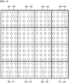
- FIG. 12 illustrates a quantization orthogonal transform coefficient to be processed.
- the quantization orthogonal transform coefficient will be referred to as a differential coefficient.
- a differential coefficient of 16 ⁇ 16 to be processed is partitioned into sub blocks 401 to 416 each having the size of 4 ⁇ 4, and scanning in units of sub blocks is performed first.
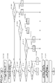
- a sub block to be processed is determined in accordance with the scanning sequence to be described later (S101) .
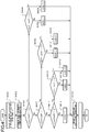
- the scanning sequence of sub blocks is denoted by reference numeral 902 illustrated in FIG. 7 .
- the scanning sequence of sub blocks is denoted by reference numeral 902 illustrated in FIG. 7 .
- scanning is started from a sub block disposed on the lower rightmost side of the differential coefficient region, scanning according to a rule of the lower right side to the upper left side and the upper right side to the upper left side is performed, and the scanning is completed at a sub block disposed on the upper leftmost side.
- Reference numeral 901 illustrated in FIG. 7 illustrates the scanning sequence of sub blocks using arrows. In a case where the scanning sequence illustrated in FIG. 7 is applied, in all the sub blocks to be processed, the scanning of sub blocks spatially positioned respectively on the right side and the lower side is in the completed state.
- step S102 the decoding process of all the differential coefficient values of the sub block to be processed is performed. After the decoding of the sub block differential coefficient values is completed, the process proceeds to step S101.
- the significant sub block information is decoded (S201) .
- the significant sub block information is a one-bit flag used for representing the presence of a differential coefficient having a value other than "0" in a sub block to be processed. In a case where the significant sub block information is "1", it represents that at least one differential coefficient having a value other than "0" is present in a sub block to be processed. On the other hand, in a case where the significant sub block information is "0", it represents that all the differential coefficients of a sub block to be processed are "0"s.
- the value of the significant sub block information is determined (S202) .
- the significant sub block information has a value of "0”
- all the differential coefficient values of the sub block to be processed are set to "0” (S209), and the sub block differential coefficient value decoding process ends.
- the decoding process of all the significant differential coefficient information of the sub block to be processed is performed (S203).
- the significant differential coefficient information is a one-bit flag used for representing that a differential coefficient value of a processing target position is not "0". In a case where the significant coefficient information is "1”, it represents that the differential coefficient value of the processing target position is not "0". On the other hand, in a case where the significant coefficient information is "0”, it represents that the differential coefficient value of the processing target position is "0".
- the decoding sequence of the significant differential coefficient information of a sub block will be described later in detail. After the decoding of all the significant differential coefficient information of the sub block is completed, the process proceeds to the decoding of differential coefficient values that is performed in step S204.
- step S204 the decoding process of differential coefficient values is performed.
- the decoding process of differential coefficient values will be described later in detail. After the completion of the decoding process of differential coefficient values, the process proceeds to step S101, and the scanning of the next sub block is performed.
- step S203 The sequence of decoding of the significant differential coefficient information of the sub block that is performed in step S203 will be described with reference to a flowchart illustrated in FIG. 3 .
- a sub block to be processed is determined in accordance with a predetermined scanning sequence (S301).
- the scanning sequence of differential coefficients within the sub block similarly to the scanning sequence of the sub block in the differential coefficient region, is assumed to follow the rule illustrated in FIG. 7 .
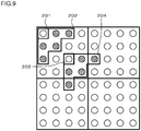
- FIG. 9 illustrates an example of the differential coefficient position used for calculating the neighboring significant differential coefficient sum countCoeff.
- Reference numeral 202 denotes neighboring differential coefficients of a case where the processing target position is as denoted by reference numeral 201
- reference numeral 204 denotes neighboring differential coefficients of a case where the processing target position is as denoted by reference numeral 203. As illustrated in FIG.
- five differential coefficients that are located respectively on the right side and the lower side of the processing target differential coefficient position and are neighboring to the processing target differential coefficient position are set as neighboring differential coefficients. Since the scanning sequence of differential coefficients follows the sequence illustrated in FIG. 7 , the decoding of differential coefficients that belong to the same sub block as that of the processing target differential coefficient and are located respectively on the right side and the lower side of the processing target differential coefficient position is completed. Similarly, the decoding of the significant differential coefficients belonging to sub blocks located respectively on the right side and the lower side of the sub block to which the processing target position belongs is completed.
- the neighboring differential coefficient sum countCoeff is a variable used for estimating the occurrence probability of the significant differential coefficient.
- the significant differential coefficient As the significant differential coefficient, "1" may be easily concentrated in the low region, and "0" may be easily concentrated in the high region. Since the significant differential coefficients have a spatial correlation, differential coefficients neighboring to the processing target position are set as targets for the calculation of the neighboring differential coefficient sum countCoeff. The neighboring differential coefficients representing the outside of the differential coefficient region are excluded from the calculation of the neighboring significant coefficient sum countCoeff.
- the neighboring significant coefficient sum countCoeff is "0" (S303).
- a context index ctxIdx used for decoding the significant differential coefficient information is set to "0" (S304), and the significant differential coefficient information is decoded by using a context that corresponds to the context index ctxIdx. Then, the significant differential coefficient information is set to the differential coefficient value (S308).
- the neighboring significant coefficient sum countCoeff is not "0"
- the context index ctxIdx used for decoding the significant differential coefficient information is set to "1" (S306), and the significant differential coefficient information is decoded by using a context that corresponds to the context index ctxIdx. Then, the significant differential coefficient information is set to the differential coefficient value (S308).
- the context index ctxIdx used for decoding the significant differential coefficient information is set to "2" (S307), and the significant differential coefficient information is decoded by using a context that corresponds to the context index ctxIdx. Then, the significant differential coefficient information is set to the differential coefficient value (S308).
- a context is a variable used for storing the occurrence probability of information to be decoded, and the assignment of a code word changes based on the occurrence probability represented by the context.
- three contexts coding the significant differential coefficient are defined, and the context decoding the significant differential coefficient is determined based on the magnitude of the neighboring significant differential coefficient sum.
- the significant coefficient information tends to be concentrated in the low region component.
- the significant coefficient information has a high correlation with the neighboring significant coefficient, and it is reasonable to perform switching among contexts based on the number of pieces of the neighboring significant coefficient information from the viewpoint of the coding efficiency.
- a sub block to be processed is determined in accordance with a predetermined scanning sequence (S501).
- the scanning sequence of differential coefficients disposed within a sub block similarly to the scanning sequence of the significant differential coefficient information, is assumed to follow the rule illustrated in FIG. 7 .
- the decoding process of differential coefficient values is completed, and the process proceeds to the sequence (S101) of determining the next sub block.
- the absolute value of the differential coefficient of the processing target differential coefficient position is decoded (S503).
- this sequence it is determined that the differential coefficient value is not "0", and, as a bitstream, a code word corresponding to a value derived by decreasing one from the absolute value of the differential coefficient is coded. Accordingly, as the absolute value of the differential coefficient, a value derived by adding "1" to a value that is derived by performing entropy decoding of a code word is set.
- a differential coefficient value is determined based on the absolute value of the differential coefficient and the sign of the differential coefficient.
- a differential coefficient 201 illustrated in FIG. 9 is scanned last in the sub block, and the scanning sequence thereof is 16 as is denoted by reference numeral 902 illustrated in FIG. 7 .
- the scanning sequence of a position neighboring to the lower side of the differential coefficient 201 is 15 and is scanned immediately before the differential coefficient 201.
- the context index ctxIdx that is necessary for decoding the significant differential coefficient information of the differential coefficient 201 is calculated based on the significant differential coefficient sum of the differential coefficients 202, the context index ctxIdx of the differential coefficient 201 cannot be determined until the decoding of the significant differential coefficient information of the differential coefficient 202 is completed. This means that it is necessary to process the calculation of the context index ctxIdx and the decoding of the significant differential coefficient information in order for all the significant differential coefficient information within the sub block, and a decrease in the time or the calculation amount through parallel processing cannot be obtained.
- the occupancy rate of the differential coefficient in the bitstream is high, and the context index calculating process and the decoding process of the significant differential coefficient information have a long time and a large calculation amount occupied in the entire decoding process.
- the decoding process of the significant coefficient information is the most significant bottleneck in the real-time decoding process.
- Patent Literature 1 a technique for decreasing a processing delay relating to a decoding process by arranging a context for a syntax element having a high occurrence frequency in a memory having a short access delay time has been disclosed.
- the technique disclosed in Patent Literature 1 does not solve the dependency between the calculation of a context index and the decoding of a syntax element and cannot perform the processes thereof in a parallel manner, whereby it cannot be an essential solution for the processing delay.
- an embodiment of the present invention provides a picture coding technology that, in the coding/decoding of differential coefficients, eliminates the dependency between the calculation of context indexes and the coding/decoding of the significant differential coefficient information, realizes a context index calculating method that can perform processes in a parallel manner and has a small amount of calculation, and has a simple circuit configuration so as to be appropriate for real-time processing.
- a picture coding technology having high coding efficiency is provided.
- a "block to be processed” is a coding target block in the case of a coding process performed by a picture coding device and is a decoding target block in the case of a decoding process performed by a picture decoding device.
- a "processed block” is a decoded block of which coding has been completed in the case of a coding process performed by the picture coding device and is a block of which decoding has been completed in the case of a decoding process performed by the picture decoding device.
- FIG. 5 is a block diagram that illustrates the configuration of the picture coding device according to an embodiment.
- the picture coding device according to the embodiment includes: a subtractor 501; an orthogonal transformer/quantizer 502; an inverse quantizer/inverse transformer 503; an adder 504; a decoded picture memory 505; a predictor 506; a differential information encoder 507; a prediction information encoder 508; and a mode determiner 509.
- the mode determiner 509 tentatively codes all the prediction candidates and determines prediction information that is optimal to each block of the picture.
- the prediction information a partitioned block size and a prediction mode representing an inter prediction or an intra prediction.
- the prediction mode is the inter prediction
- motion information such as a motion vector and a reference picture index is included in the prediction information.
- an intra prediction mode is included in the prediction information.
- the mode determiner 509 gives the determined prediction information to the predictor 506 and the prediction information encoder 508.
- the prediction information encoder 508 performs variable length coding of the input prediction information and outputs a bitstream of the prediction information.
- the predictor 506 generates a predicted picture using the input prediction information and the decoded picture stored in the decoded picture memory 505 and gives the generated predicted picture to the subtractor 501.
- the subtractor 501 generates a differential picture by subtracting the predicted picture from the original picture that is a coding target and gives the generated differential signal to the orthogonal transformer/quantizer 502.
- the orthogonal transformer/quantizer 502 generates differential coefficients by performing an orthogonal transform and quantization of the differential picture and gives the generated differential coefficients to the inverse quantizer/inverse transformer 503 and the differential information encoder 507.
- the differential information encoder 507 performs entropy coding of the differential coefficients and outputs a bitstream of the differential information.
- the inverse quantizer/inverse transformer 503 generates a decoded differential signal by performing the inverse quantization and the inverse orthogonal transform of the differential coefficients received from the orthogonal transformer/quantizer 502 and gives the generated decoded differential signal to the adder 504.
- the adder 504 generates a decoded picture by adding the predicted picture and the decoded differential signal and stores the generated decoded picture in the decoded picture memory 505.
- FIG. 6 is a block diagram that illustrates the configuration of the picture decoding device according to an embodiment.
- the picture decoding device according to the embodiment includes: a differential information decoder 801; an inverse quantizer/inverse transformer 802; a prediction information decoder 803; an adder 804; a decoded picture memory 805; and a predictor 806.
- the decoding process of the picture decoding device illustrated in FIG. 6 corresponds to the decoding process arranged inside the picture coding device illustrated in FIG. 5 . Accordingly, the configurations of the inverse quantizer/inverse transformer 802, the adder 804, the decoded picture memory 805, and the predictor 806 illustrated in FIG. 8 have functions respectively corresponding to the configurations of the inverse quantizer/inverse transformer 503, the adder 504, the decoded picture memory 505, and the predictor 506 of the picture coding device illustrated in FIG. 5 .
- the prediction information decoder 803 generates prediction information by performing entropy decoding of an input prediction information bitstream and gives the generated prediction information to the predictor 806.
- the predictor 806 generates a predicted picture by using the input prediction information and the decoded picture that is stored in the decoded picture memory 805 and gives the generated predicted picture to the adder 804.
- the differential information decoder 801 generates differential information by performing entropy decoding of the differential information. Then, the differential information decoder 801 gives the generated differential information to the inverse quantizer/inverse transformer 802.
- the inverse quantizer/inverse transformer 802 generates a decoded differential signal by performing the inverse quantization and the inverse orthogonal transform of the differential information received from the differential information decoder 801 and gives the generated decoded differential signal to the adder 804.
- the adder 804 generates a decoded picture by adding the predicted picture and the decoded differential signal together, stores the generated decoded picture in the decoded picture memory 805, and outputs the generated decoded picture.
- the coding process and the decoding process of differential coefficients according to an embodiment of the present invention are respectively performed by the differential information encoder 507 of the motion picture coding device illustrated in FIG. 5 and the differential information decoder 801 of the motion picture decoding device illustrated in FIG. 8 .
- the coding process and the decoding process of the differential information according to an embodiment will be described in detail.
- the screen is hierarchically partitioned into rectangular blocks, and the blocks are processed in order according to a predetermined processing sequence.
- Each block that is partitioned will be referred to as a coding block.
- a block 1817 illustrated in FIG. 14 is a maximum unit of the partition according to the embodiment and will be referred to as a maximum coding block.
- a block 1816 illustrated in FIG. 14 is a minimum unit of the partition according to the embodiment and will be referred to as a minimum coding block.
- the minimum coding block will be described as a block of 4 ⁇ 4 pixels and the maximum coding block will be described as a block of 16 ⁇ 16 pixels.
- a unit in which the intra prediction is performed will be referred to as a prediction block.
- the prediction block has several sizes as below that are larger than or equal to that of the minimum coding block and are smaller than or equal to that of the maximum coding block.
- blocks 1802, 1803, and 1804 are 16 ⁇ 16 blocks
- blocks 1805, 1810, 1811, and 1801 are 8 ⁇ 8 blocks
- blocks 1806, 1807, 1808, and 1809 are 4 ⁇ 4 blocks.
- Blocks 1812, 1813, 1814, and 1815 are blocks that have not been processed, and the coding block sizes thereof are not determined.
- an optimal prediction block size is determined, and blocks of the prediction block size are coded.
- the prediction block size is derived from the bitstream.
- the description will be presented with the prediction block being assumed as the processing unit.
- the unit in which the quantization and the orthogonal transform are performed is the same as the unit of the prediction block, in the coding process and the decoding process, the scanning is performed with the differential coefficient region being partitioned into a plurality of sub blocks.
- the size of the sub block is a size of 4 ⁇ 4.
- FIG. 12 illustrates a differential coefficient region of a size of 16 ⁇ 16.
- reference numerals 401 to 416 represent sub blocks.
- the unit in which the quantization and the orthogonal transform are performed may be determined independently from the unit of the prediction block.
- FIG. 15 is a block diagram that illustrates the detailed configuration of the differential information encoder 507, which is illustrated in FIG. 5 , according to the first example.
- the differential information encoder 507 according to the first example includes: an arithmetic encoder 701; a differential coefficient buffer 702; a coding controller 703; a context memory 704; and a scan controller 705.
- the coding controller 703 includes: a significant coefficient information coding controller 706; a differential coefficient value coding controller 707; and a significant sub block information coding controller 708.
- the scan controller 705 determines a sub block to be processed (S601). When the scanning of all the sub blocks is completed, the decoding process of differential coefficients ends.
- Reference numeral 902 represented in FIG. 7 illustrates the scanning sequence of sub blocks. In this sequence, scanning is started from a sub block disposed on the lower rightmost side of the differential coefficient region, scanning according to a rule of the lower right side to the upper left side and the upper right side to the upper left side is performed, and the scanning is completed at a sub block disposed on the upper leftmost side. As described above, the context is updated in accordance with the coding process.
- Reference numeral 901 illustrated in FIG. 7 is a diagram that illustrates the scanning sequence of sub blocks using arrows. In a case where the scanning sequence illustrated in FIG. 7 is applied, the scanning of sub blocks spatially positioned respectively on the right side and the lower side of the sub block to be processed is in the completed state. The coding process of the sub block to be processed is performed (S602).
- the significant sub block information coding controller 708 derives a sub block to be processed from the differential coefficient buffer 702. All the differential coefficients of the sub block are scanned, and, in a case where all the differential coefficient values are "0", the significant sub block information is set to "0". Otherwise (in a case where there is at least one differential coefficient value other than "0"), the significant sub block information is set to "1" (S701).
- the significant sub block information coding controller 708 refers to differential coefficients that are neighboring to the sub block to be processed and are included in the sub block that has been decoded from the differential coefficient buffer 702 and determines a context index ctxIdx used for coding the significant sub block information. Then, the significant sub block information coding controller 708 reads a context that corresponds to the context index ctxIdx from the context memory 704. Then, the significant sub block information and the context are transmitted to the arithmetic encoder 701. Then, arithmetic encoder 701 codes the significant sub block information using the context (S702).
- the significant sub block information coding controller 708 determines the value of the significant sub block information (S703). When the significant sub block information is "0", the sub block differential coefficient value coding process ends, and the process proceeds to step S601.
- the coding process of all the significant differential coefficient information of the sub block to be processed is performed (S704).
- the coding sequence of the significant differential coefficient information will be described later in detail.
- the process proceeds to the coding of differential coefficient values of step S704.
- the differential coefficient value coding controller 707 performs the coding process of all the differential coefficient values of the sub block to be processed (S705) .
- the coding sequence of differential coefficient values of the sub block will be described later in detail. After the coding of all the differential coefficient values of the sub block is completed, the process proceeds to step S601.
- the significant coefficient information coding controller 706 calculates a sum of differential coefficients, which have values other than "0", neighboring to the sub block to be processed, in other words, a neighboring significant coefficient sum countCoeff (S801).
- differential coefficients that belong to sub blocks spatially disposed respectively on the right side and the lower side of the sub block to be processed and are neighboring to the sub block to be processed are defined as neighboring differential coefficients.
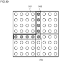
- FIG. 10 illustrates the positions of the neighboring differential coefficients.
- Reference numeral 301 represents a sub block to be processed, and reference numeral 302 represents the neighboring differential coefficients.
- a neighboring differential coefficient representing the outside of the differential coefficient region is excluded from the calculation of the neighboring significant coefficient sum countCoeff.
- a differential coefficient 303 that belongs to both sub blocks disposed on the right side and the left side of the sub block to be processed may be configured to be included in the neighboring differential coefficients or may be configured not to be included therein. In the configuration in which the differential coefficient 303 is included in the neighboring differential coefficients, the number of the neighboring differential coefficients increases, and the occurrence probability of the significant differential coefficient information can be estimated with high accuracy.
- the amount of calculation and the circuit scale can be decreased by reducing the adding process relating to the neighboring significant coefficient sum countCoeff and reducing the boundary determining process of the differential coefficient region.
- the significant coefficient information coding controller 706 determines differential coefficients that are the processing targets (S802).
- the scanning sequence of differential coefficients within the sub block similarly to the scanning sequence of sub blocks in the differential coefficient region, follows the rule represented in FIG. 7 .
- the coding process of the significant differential coefficients is completed, and the process proceeds to the coding sequence (S704) of differential coefficient values.
- the significant coefficient information coding controller 706 determines whether or not the neighboring significant coefficient sum countCoeff is "0" (S803).
- the processing target differential coefficient position within the sub block to be processed is determined (S804) .
- a horizontal differential coefficient position is posX
- a vertical differential coefficient position is posY
- a context index ctxIdx used for coding the significant coefficient information is set to "1" (S805). Otherwise (pos > 2), the context index ctxIdx is set to "0" (S806) .
- the neighboring significant coefficient sum countCoeff is not "0"
- the processing target differential coefficient position within the sub block to be processed is determined (S408).
- the context index ctxIdx used for decoding the significant coefficient information is set to "1" (S809). Otherwise (pos > 3), the context index ctxIdx is set to "0" (S810) .
- the neighboring significant coefficient sum countCoeff is not smaller than or equal to "1"
- the processing target differential coefficient position within the sub block to be processed is determined (S812).
- the context index ctxIdx used for decoding the significant coefficient information is set to "2" (S813). Otherwise (pos > 2), the context index ctxIdx is set to "1" (S814) .
- the context index ctxIdx used for decoding the significant coefficient information is set to "2" (S815).
- the definition of the context index ctxIdx of a case where the neighboring significant coefficient sum countCoeff > 2 is denoted by reference numeral 605 in FIG. 11 .
- the significant coefficient information coding controller 706 derives the differential coefficient of the processing target position from the differential coefficient buffer 702. In a case where the differential coefficient value is not "0", the significant differential coefficient information is set to "1". Otherwise (in a case where the differential coefficient value is "0"), the significant differential coefficient information is set to "0" (S816).
- the significant coefficient information coding controller 706 transmits the significant differential coefficient information and the context to the arithmetic encoder 701.
- the arithmetic encoder 701 codes the significant differential coefficient information using the context (S817).
- the differential coefficient value coding controller 707 determines a differential coefficient that is the processing target (S901).
- the scanning sequence of differential coefficients disposed within a sub block similarly to the scanning sequence of the significant differential coefficients, is assumed to follow the rule illustrated in FIG. 7 .
- the coding process of differential coefficient values is completed, and the process proceeds to the sequence (S601) of determining the next sub block.
- the differential coefficient value coding controller 707 determines whether or not the differential coefficient value of the processing target differential coefficient position is "0" (S902). In a case where the differential coefficient value of the processing target differential coefficient position is "0", the coding of the differential coefficient value of the processing target differential coefficient position is completed, and the process proceeds to step S901.
- the absolute value of the coded differential coefficient of the processing target differential coefficient position and the sign are calculated (S903 and S904).
- the differential coefficient value is determined not to be "0". Accordingly, the absolute value of the coded differential coefficient is set as a value derived by decreasing one from the absolute value of the differential coefficient.
- the sign is set to "0".
- the sign is set to "1".
- the differential coefficient value coding controller 707 transmits a coding absolute value and the context to the arithmetic encoder 701.
- the arithmetic encoder 701 codes the coding absolute value using the context (S905).
- the differential coefficient value coding controller 707 transmits a sign and the context to the arithmetic encoder 701.
- the arithmetic encoder 701 codes the coding absolute value using the context (S905).
- FIG. 8 is a block diagram that illustrates the detailed configuration of the differential information decoder 801, which is illustrated in FIG. 6 , according to the first example.
- the differential information decoder 801 according to the first example includes: an arithmetic decoder 1001; a differential coefficient buffer 1002; a decoding controller 1003; a context memory 1004; and a scan controller 1005.
- the decoding controller 1003 includes: a significant coefficient information decoding controller 1006; a differential coefficient value decoding controller 1007; and a significant sub block information decoding controller 1008.
- the configurations of the differential coefficient buffer 1002, the context memory 1004, and the scan controller 1005 of the differential information encoder illustrated in FIG. 8 respectively have functions corresponding to the configurations of the differential coefficient buffer 702, the context memory 704, and the scan controller 705 illustrated in FIG. 15 .
- the scan controller 1005 determines a sub block to be processed (S101) .
- the decoding process of differential coefficients ends.
- Reference numeral 902 represented in FIG. 7 illustrates the scanning sequence of sub blocks. In this sequence, scanning is started from a sub block disposed on the lower rightmost side of the differential coefficient region, scanning according to a rule of the lower right side to the upper left side and the upper right side to the upper left side is performed, and the scanning is completed at a sub block disposed on the upper leftmost side.
- Reference numeral 901 represented in FIG. 7 illustrates the scanning sequence of sub blocks using arrows. In a case where the scanning sequence illustrated in FIG. 7 is applied, the scanning of sub blocks spatially positioned respectively on the right side and the lower side of the sub block to be processed is in the completed state.
- the decoding process of the sub block to be processed is performed (S102).
- the significant sub block information decoding controller 1008 refers to differential coefficients that are neighboring to the sub block to be processed and are included in the sub block that has been decoded from the differential coefficient buffer 1002, determines a context used for decoding the significant sub block information, and reads the determined context from the context memory 1004.
- the significant sub block information decoding controller 1008 transmits a decoding command together with the context to the arithmetic decoder 1001.
- the arithmetic decoder 1001 performs the decoding process of a bitstream by using the context, thereby decoding the significant sub block information (S201).
- the significant sub block information decoding controller 1008 determines the value of the significant sub block information (S202) .
- S202 significant sub block information
- all the differential coefficient values of the processing target sub block stored in the differential coefficient buffer 1002 are set to "0" (S209), and the decoding process of sub block differential coefficient values ends.
- the decoding process of all the significant differential coefficient information of the sub block to be processed is performed (S203).
- the sequence of decoding of the significant differential coefficient information of a sub block will be described later in detail. After the decoding of all the significant differential coefficient information of the sub block is completed, the process proceeds to the decoding of differential coefficient values of step S204.
- step S204 the decoding process of all the differential coefficient values of the sub block to be processed is performed.
- the sequence of the decoding of the differential coefficient values of the sub block will be described later in detail. After the decoding of all the differential coefficient values of the sub block is completed, the process proceeds to step S101.
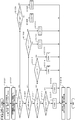
- the significant coefficient information decoding controller 1006 calculates a sum countCoeff of the number of the neighboring significant differential coefficients of the processing target differential coefficient position (S401).
- differential coefficients that belong to sub blocks spatially disposed respectively on the right side and the lower side of the sub block to be processed and are neighboring to the sub block to be processed are defined as neighboring differential coefficients.
- FIG. 10 illustrates the positions of the neighboring differential coefficients.
- Reference numeral 301 represents a sub block to be processed, and reference numeral 302 represents the neighboring differential coefficients.
- a neighboring differential coefficient representing the outside of the differential coefficient region is excluded from the calculation of the neighboring significant coefficient sum countCoeff.
- a differential coefficient 303 that belongs to both sub blocks disposed on the right side and the lower side of the sub block to be processed may be configured to be included in the neighboring differential coefficients or may be configured not to be included therein. In the configuration in which the differential coefficient 303 is included in the neighboring differential coefficients, the number of the neighboring differential coefficients increases, and the occurrence probability of the significant differential coefficient information can be estimated with high accuracy.
- the amount of calculation and the circuit scale can be decreased by reducing the adding process relating to the neighboring significant coefficient sum countCoeff and reducing the boundary determining process of the differential coefficient region.
- the significant coefficient information decoding controller 1006 determines differential coefficients that are the processing targets (S402).
- the scanning sequence of differential coefficients within the sub block similarly to the scanning sequence of sub blocks in the differential coefficient region, follows the rule represented in FIG. 7 .
- the decoding process of the significant differential coefficients is completed, and the process proceeds to the decoding sequence (S204) of differential coefficient values.
- the significant coefficient information decoding controller 1006 determines whether or not the neighboring significant coefficient sum countCoeff is "0" (S403) .
- the processing target differential coefficient position within the sub block to be processed is determined (S404) .
- a horizontal differential coefficient position is posX
- a vertical differential coefficient position is posY
- a context index ctxIdx used for decoding the significant coefficient information is set to "1" (S405) .
- the context index ctxIdx is set to "0" (S406) .
- the neighboring significant coefficient sum countCoeff is not "0"
- the processing target differential coefficient position within the sub block to be processed is determined (S408).
- the context index ctxIdx used for decoding the significant coefficient information is set to "1" (S409). Otherwise (pos > 3), the context index ctxIdx is set to "0" (S410) .
- a decoding command is transmitted to the arithmetic decoder 1001 together with the context.
- the arithmetic decoder 1001 performs a decoding process of a bitstream using the context, thereby decoding the significant differential coefficient information (S416).
- the neighboring significant coefficient sum countCoeff is not smaller than or equal to "1"
- the processing target differential coefficient position within the sub block to be processed is determined (S412).
- the context index ctxIdx used for decoding the significant coefficient information is set to "2" (S413). Otherwise (pos > 2), the context index ctxIdx is set to "1" (S414) .
- a decoding command is transmitted to the arithmetic decoder 1001 together with the context.
- the arithmetic decoder 1001 performs a decoding process of a bitstream using the context, thereby decoding the significant differential coefficient information (S416).
- the context index ctxIdx used for decoding the significant coefficient information is set to "2" (S415).
- the definition of the context index ctxIdx of a case where the neighboring significant coefficient sum countCoeff > 2 is denoted by reference numeral 605 in FIG. 11 .
- the neighboring significant coefficient sum countCoeff When the neighboring significant coefficient sum countCoeff is large, there is a high possibility that all the significant coefficient information within the sub block to be processed is "1". Accordingly, in the above-described sequence, in a case where the neighboring significant coefficient sum countCoeff is larger than or equal to "3", the context index ctxIdx is set to "2" regardless of the value of the processing target differential coefficient position pos. In addition, the determination criterion for the neighboring significant coefficient sum countCoeff may be subdivided.
- the neighboring significant coefficient countCoeff is larger than or equal to "3”
- the definition of the context index that is denoted by reference numeral 604 illustrated in FIG. 11 is configured to be taken
- the definition of the context index that is denoted by reference numeral 605 illustrated in FIG. 11 is configured to be taken.
- the correlation use efficiency of the neighboring information is improved, and accordingly, the coding efficiency can be improved.
- the orthogonal transform coefficients of a picture may be easily concentrated in the low region component, and there is a high possibility that the significant coefficient information is "1".
- the high region component is quantized in a rough manner in many cases, and accordingly, there is a high possibility that the coefficient value of the high region component is "0", and the significant coefficient information of the high region component is "0".
- Such a characteristic is not limited to the entire differential coefficient region but is the same for each sub block, and it can be regarded that, for a component present on the low region side of the sub block, a probability that the significant coefficient information is "1" is higher than that for a component present on the high region side of the same sub block.
- Setting the value of the context index ctxIdx of the significant differential coefficient information presented in the low region within the sub block to be larger than the value of the context index ctxIdx of the significant differential coefficient information present in the high region leads to the improvement of the estimation accuracy of the occurrence probability of the significant coefficient information.
- the neighboring significant coefficient sum tends to be small in the high region in which the probability that the significant differential coefficient is "0" is high, and the neighboring significant coefficient sum tends to increase in the low region in which the probability that the significant differential coefficient is "1" is high.
- the neighboring significant coefficient sum as an index representing the degree of inclusion of the significant differential coefficient information in the sub block to be processed improves the estimation accuracy of the occurrence probability of the significant coefficient information.
- the context indexes of all the coefficient positions within the sub block can be calculated.
- the amount of calculation of the neighboring significant differential coefficient sum can be reduced.
- the differential coefficient belonging to the processing target sub block is not targeted for the neighboring significant differential coefficient sum, and accordingly, there is no dependency within the sub block for the calculation of context indexes. Since the context indexes for all the significant differential coefficients can be calculated from the start of the sub block, the calculation of the context indexes can be performed in parallel with the decoding process of the significant differential coefficient information. Thus, a processing delay relating to the decoding of significant coefficient information having a high occurrence frequency in the bitstream can be decreased.
- the context calculation may be performed by referring to the significant sub block information instead of the neighboring significant coefficient.
- the amount of calculation and the circuit scale can be reduced.
- the position of the sub block can be reflected on the context calculation.
- the low region component has a characteristic having the occurrence probability of the significant coefficient to be higher than that of the high region.
- areas denoted by reference numerals 1101, 1102, 1103, 1104, 1105, and 1109 are low region components
- areas denoted by reference numerals 1106, 1107, 1108, 1110, 1111, 1112, 1113, 1114, 1115, and 1116 are high-region areas.
- predetermined offsets corresponding to the positions of sub blocks may be configured to be added to the context indexes ctxIdx described above for the low-region areas, or a conditional branch according to the position of the sub block may be configured to be added during the calculation of the context indexes ctxIdx described above.
- the context indexes may be calculated by using the sum of the absolute values of neighboring coefficients instead of the neighboring significant differential coefficient sum.
- the absolute value of the differential coefficient of the low-region component is large, and accordingly, by setting a context in which the occurrence probability of the significant differential coefficient information increases in a case where the sum of the absolute values of the neighboring differential coefficients is large, the coding efficiency can be improved.
- the accuracy of the context estimation can be improved.
- an inter prediction capable of referring to a plurality of decoded pictures has characteristics that the prediction accuracy is high and a differential cannot easily occur.
- the significant coefficient information decoding controller 1006 determines differential coefficients that are the processing targets (S501).
- the scanning sequence of differential coefficients within the sub block similarly to the scanning sequence of the significant differential coefficients, follows the rule represented in FIG. 7 .
- the decoding process of the differential coefficients is completed, and the process proceeds to the sequence (S101) of determining the next sub block.
- the significant coefficient information decoding controller 1006 determines whether or not the differential coefficient value of the processing target differential coefficient position is "0" (S502). In a case where the differential coefficient value of the processing target differential coefficient position is "0", the decoding of the differential coefficient value of the processing target differential coefficient position is completed, and the process proceeds to step S501.
- the absolute value of the differential coefficient of the processing target differential coefficient position is decoded (S503).
- this sequence it is determined that the differential coefficient value is not "0", and, as a bitstream, a code word corresponding to a value derived by decreasing one from the absolute value of the differential coefficient is decoded. Accordingly, as the absolute value of the differential coefficient, a value derived by adding "1" to a value that is derived by performing entropy decoding of a code word is set.
- a differential coefficient value is determined based on the absolute value of the differential coefficient and the sign of the differential coefficient.
- the differential coefficient value has correlation with the neighboring coefficient values and has concentration in the low region component.
- a differential information encoder 507 according to the second example similarly to the differential information encoder 507 according to the first example illustrated in FIG. 15 , includes: an arithmetic encoder 701; a differential coefficient buffer 702; a coding controller 703; a context memory 704; and a scan controller 705.
- the coding controller 703 includes: a significant coefficient information coding controller 706; a differential coefficient value coding controller 707; and a significant sub block information coding controller 708.
- the coding sequence of the differential information according to this example is the same as that of the first example except for the sequence (S704 illustrated in FIG. 17 ) of the coding process of the significant differential coefficient information, and thus, hereinafter, the sequence of the coding process of the significant differential coefficient information according to this example will be described with reference to a flowchart illustrated in FIG. 21 .
- the significant coefficient information coding controller 706 derives the significant sub block information of decoded sub blocks that are respectively neighboring to the right side and the lower side of a sub block to be processed. It is set such that the significant sub block information of the sub block neighboring to the right side is sigGroupRight, and the significant sub block information of the sub block neighboring to the lower side is sigGroupBottom (S1001).
- the significant coefficient information coding controller 706 determines differential coefficients that are the processing targets (S1002).
- the scanning sequence of differential coefficients within the sub block similarly to the scanning sequence of sub blocks in the differential coefficient region, follows the rule represented in FIG. 7 .
- the coding process of the significant differential coefficients is completed, and the process proceeds to the coding sequence (S704) of differential coefficient values.
- the significant coefficient information coding controller 706 evaluates the significant sub block information sigGroupRight and the significant sub block information sigGroupBottom (S1003).
- the position of the processing target differential coefficient within the sub block to be processed is determined (S1004).
- a horizontal differential coefficient position is posX
- a vertical differential coefficient position is posY
- the definition of the context index ctxIdx of a case where both the significant sub block information sigGroupRight and the significant sub block information sigGroupBottom are "0” is denoted by reference numeral 1201 in FIG. 23 .
- the context index ctxIdx is set to "0" (S1010).
- the definition of the context index ctxIdx of a case where the significant sub block information sigGroupRight is "1" and the significant sub block information sigGroupBottom is "0" is denoted by reference numeral 1202 in FIG. 23 .
- the context index ctxIdx is set to "0" (S1014).
- the definition of the context index ctxIdx of a case where the significant sub block information sigGroupRight is "0" and the significant sub block information sigGroupBottom is "1" is denoted by reference numeral 1203 in FIG. 23 .
- the sequence of setting the context index ctxIdx of a case where the significant sub block information sigGroupRight is "0" and the significant sub block information sigGroupBottom is "1” is a process in which the X-direction process and the Y-direction process of a case where the significant sub block information sigGroupRight is "1" and the significant sub block information sigGroupBottom is "0" are interchanged.
- the process can be configured to be common, and the circuit scale of the hardware or the coding amount of the software can be reduced.
- the position of the processing target differential coefficient within the sub block to be processed is determined (S1015).
- the context index ctxIdx used for decoding the significant coefficient information is set to "2" (S1016). Otherwise (pos > 5), the context index ctxIdx is set to "1" (S1017) .
- the significant coefficient information coding controller 706 derives the differential coefficient of the processing target position from the differential coefficient buffer 702. In a case where the differential coefficient value is not "0", the significant differential coefficient information is set to "1". Otherwise (in a case where the differential coefficient value is "0"), the significant differential coefficient information is set to "0" (S1018).
- the significant coefficient information coding controller 706 transmits the significant differential coefficient information and the context to the arithmetic encoder 701.
- the arithmetic encoder 701 codes the significant differential coefficient information using the context (S1019).
- the differential information decoder 801 according to the second example similarly to the differential information decoder 801 according to the first example illustrated in FIG. 8 , includes: an arithmetic decoder 1001; a differential coefficient buffer 1002; a decoding controller 1003; a context memory 1004; and a scan controller 1005.
- the decoding controller 1003 includes: a significant coefficient information decoding controller 1006; a differential coefficient value decoding controller 1007; and a significant sub block information decoding controller 1008.
- a differential information decoding process performed by the differential information decoder 801 illustrated in FIG. 8 corresponds to the differential information coding process performed by the differential information encoder 507 illustrated in FIG. 5 .
- the configurations of the differential coefficient buffer 1002, the context memory 1004, and the scan controller 1005 of the differential information encoder illustrated in FIG. 8 respectively have functions corresponding to the configurations of the differential coefficient buffer 702, the context memory 704, and the scan controller 705 illustrated in FIG. 15 .
- the decoding sequence of the differential information according to this example is the same as that of the first example except for the sequence (S203 illustrated in FIG. 2 ) of the coding process of the significant differential coefficient information, hereinafter, the sequence of the decoding process of the significant differential coefficient information according to this example will be described with reference to a flowchart illustrated in FIG. 22 .
- the significant coefficient information decoding controller 1006 derives the significant sub block information of decoded sub blocks that are neighboring to the right side and the lower side of the sub block to be processed.
- the significant sub block information of the sub block neighboring to the right side will be denoted by sigGroupRight, and the significant sub block information of the sub block neighboring to the lower side will be denoted by sigGroupBottom (S1101).
- the significant coefficient information decoding controller 1006 determines differential coefficients that are the processing targets (S1102).
- the scanning sequence of differential coefficients within the sub block similarly to the scanning sequence of sub blocks in the differential coefficient region, follows the rule represented in FIG. 7 .
- the decoding process of the significant differential coefficients is completed, and the process proceeds to the decoding sequence (S204) of differential coefficient values.
- the significant coefficient information decoding controller 1006 evaluates the significant sub block information sigGroupRight and the significant sub block information sigGroupBottom (S1103) .
- the position of the processing target differential coefficient within the sub block to be processed is determined (S1104).
- a horizontal differential coefficient position is posX
- a vertical differential coefficient position is posY
- a context index ctxIdx used for decoding the significant coefficient information is set to "1" (S1105).
- the context index ctxIdx is set to "0" (S1106) .
- the definition of the context index ctxIdx of a case where the significant sub block information sigGroupRight is "0" and the significant sub block information sigGroupBottom are "0" is denoted by reference numeral 1201 in FIG. 23 .
- the context index ctxIdx is set to "0" (S1110).
- the definition of the context index ctxIdx of a case where the significant sub block information sigGroupRight is "1" and the significant sub block information sigGroupBottom is "0" is denoted by reference numeral 1202 in FIG. 23 .
- the context index ctxIdx is set to "0" (S1114).
- the definition of the context index ctxIdx of a case where the significant sub block information sigGroupRight is "0" and the significant sub block information sigGroupBottom is "1" is denoted by reference numeral 1203 in FIG. 23 .
- the position of the processing target differential coefficient within the sub block to be processed is determined (S1117).
- the context index ctxIdx used for decoding the significant coefficient information is set to "2" (S1118). Otherwise (pos > 5), the context index ctxIdx is set to "1" (S1114).
- the definition of the context index ctxIdx of a case where both the significant sub block information sigGroupRight and the significant sub block information sigGroupBottom are "1" is denoted by reference numeral 1204 in FIG. 23 .
- a decoding command is transmitted to the arithmetic decoder 1001 together with the context.
- the arithmetic decoder 1001 performs a decoding process of a bitstream using the context, thereby decoding the significant differential coefficient information (S1116).
- the significant sub block information of the decoded neighboring sub blocks and the position of the processing target differential coefficient within the sub block are referred to, and the significant sub block information of the right side and the significant sub block information of the lower side are individually determined.
- the reason for employing such a configuration will be described.
- the orthogonal transform coefficients of a picture may be easily concentrated in the low region component, and there is a high possibility that the significant coefficient information is "1".
- the high region component is quantized in a rough manner in many cases, and accordingly, there is a high possibility that the coefficient value of the high region component is "0", and the significant coefficient information of the high region component is "0".
- Such a characteristic is not limited to the entire differential coefficient region but is the same for each sub block, and it can be regarded that, for a component present on the low region side of the sub block, a probability that the significant coefficient information is "1" is higher than that for a component present on the high region side of the same sub block.
- Setting the value of the context index ctxIdx of the significant differential coefficient information present in the low region within the sub block to be larger than the value of the context index ctxIdx of the significant differential coefficient information present in the high region leads to the improvement of the estimation accuracy of the occurrence probability of the significant coefficient information.
- the decoded neighboring significant sub block information tends to be small in the high region in which the probability that the significant differential coefficient is "0" is high, and the decoded neighboring significant sub block information tends to increase in the low region in which the probability that the significant differential coefficient is "1" is high.
- using the decoded neighboring significant sub block information as an index representing the degree of inclusion of the significant differential coefficient information in the sub block to be processed improves the estimation accuracy of the occurrence probability of the significant coefficient information.
- the decoded neighboring sub blocks are not limited thereto.
- the sub block that is neighboring to the lower right side of the sub block to be decoded is close to the sub block to be decoded and has a high correlation with the sub block to be decoded.
- the accuracy of the occurrence probabilities of significant differential coefficients can be improved.
- the sub block that is neighboring to the lower right side of the sub block to be decoded is positioned far from the sub block to be decoded and has a low correlation with the sub block to be decoded.
- the context index of the significant differential coefficient is calculated based on the right-side significant sub block information sigGroupRight, the lower-side significant sub block information sigGroupBottom, and the significant sub block information sigGroupBottomRight
- the degree of reflection of the significant differential coefficient of the significant sub block information sigGroupBottomRight on the context index is set to be low, for example, in a case where both the lower-side significant sub block information sigGroupBottom and the significant sub block information sigGroupBottomRight are "0"
- the occurrence probability of the significant differential coefficient is set to be low regardless of the value of the significant sub block information sigGroupBottomRight.
- the differential coefficient belonging to the processing target sub block is not targeted for the right-side significant sub block information sigGroupRight and the lower-side significant sub block information sigGroupBottom, and accordingly, there is no dependency within the sub block for the calculation of context indexes. Since the context indexes for all the significant differential coefficients can be calculated from the start of the sub block, the calculation of the context indexes can be performed in parallel with the decoding process of the significant differential coefficient information. Thus, a processing delay relating to the decoding of significant coefficient information having a high occurrence frequency in the bitstream can be decreased.
- the differential coefficient value has correlation with the neighboring coefficient values and has concentration in the low region component.
- the context index is calculated based on a combination of the right-side significant sub block information and the lower-side significant sub block information.
- the occurrence probability of the significant differential coefficient of the vertical high region component of the sub block to be processed is estimated to be low when a significant differential coefficient is not present on the lower side of the sub block to be processed, and the occurrence probability of the significant differential coefficient of the horizontal high region component of the sub block to be processed is estimated to be low when a significant differential coefficient is not present on the right side of the sub block to be processed, whereby an appropriate probability model of the significant differential coefficient information can be set, and the significant differential coefficient information can be efficiently coded.
- a differential information encoder 507 according to the third example similarly to the differential information encoder 507 according to the first example illustrated in FIG. 15 , includes: an arithmetic encoder 701; a differential coefficient buffer 702; a coding controller 703; a context memory 704; and a scan controller 705.
- the coding controller 703 includes: a significant coefficient information coding controller 706; a differential coefficient value coding controller 707; and a significant sub block information coding controller 708.
- the coding sequence of the differential information according to this example is the same as that of the first example except for the sequence (S704 illustrated in FIG. 17 ) of the coding process of the significant differential coefficient information, and thus, hereinafter, the sequence of the coding process of the significant differential coefficient information according to this example will be described with reference to a flowchart illustrated in FIG. 24 .
- the significant coefficient information coding controller 706 determines differential coefficients that are the processing targets (S1202).
- the scanning sequence of differential coefficients within the sub block similarly to the scanning sequence of sub blocks in the differential coefficient region, follows the rule represented in FIG. 7 .
- the coding process of the significant differential coefficients is completed, and the process proceeds to the coding sequence (S704) of differential coefficient values.
- the significant coefficient information coding controller 706 evaluates the neighboring significant index sigCoeffIndex (S1203).
- the position of the processing target differential coefficient within the sub block to be processed is determined (S1204).
- the neighboring significant index sigCoeffIndex is "0”
- the significant sub block information sigGroupBottom is "0”.
- a horizontal differential coefficient position is posX
- a vertical differential coefficient position is posY
- the context index ctxIdx used for coding the significant coefficient information is set to "1" (S1205).
- the context index ctxIdx is set to "0" (S1206).
- the definition of the context index ctxIdx of a case where the neighboring significant index sigCoeffIndex is "0" is denoted by reference numeral 1201 in FIG. 23 .
- the neighboring significant index sigCoeffIndex is not "0"
- the neighboring significant index sigCoeffIndex is "1”
- the position of the processing target differential coefficient within the sub block to be processed is determined (S1208) .
- the context index ctxIdx used for decoding the significant coefficient information is set to "1" (S1209). Otherwise (posY > 2), the context index ctxIdx is set to "0" (S1210).
- the definition of the context index ctxIdx of a case where the neighboring significant index sigCoeffIndex is "1" is denoted by reference numeral 1202 in FIG. 23 .
- the neighboring significant index sigCoeffIndex is not "1"
- the neighboring significant index sigCoeffIndex is "2”
- the position of the processing target differential coefficient within the sub block to be processed is determined (S1212) .
- the context index ctxIdx used for decoding the significant coefficient information is set to "1" (S1213) . Otherwise (posX > 2), the context index ctxIdx is set to "0" (S1214).
- the definition of the context index ctxIdx of a case where the neighboring significant index sigCoeffIndex is "2" is denoted by reference numeral 1203 in FIG. 23 .
- the sequence of setting the context index ctxIdx of a case where the neighboring significant index sigCoeffIndex is "2" is a process in which the X-direction process and the Y direction process of a case where the neighboring significant index sigCoeffIndex is "1" are interchanged.
- the process can be configured to be common, and the circuit scale of the hardware or the coding amount of the software can be reduced.
- the position of the processing target differential coefficient within the sub block to be processed is determined (S1215).
- the neighboring significant index sigCoeffIndex is "3"
- the context index ctxIdx used for decoding the significant coefficient information is set to "2" (S1216).
- the context index ctxIdx is set to "1" (S1217).
- the definition of the context index ctxIdx of a case where neighboring significant index sigCoeffIndex is "3" is denoted by reference numeral 1204 in FIG. 23 .
- the significant coefficient information coding controller 706 derives the differential coefficient of the processing target position from the differential coefficient buffer 702. In a case where the differential coefficient value is not "0", the significant differential coefficient information is set to "1". Otherwise (in a case where the differential coefficient value is "0"), the significant differential coefficient information is set to "0" (S1218).
- the significant coefficient information coding controller 706 transmits the significant differential coefficient information and the context to the arithmetic encoder 701.
- the arithmetic encoder 701 codes the significant differential coefficient information using the context (S1219).
- the differential information decoder 801 according to the third example similarly to the differential information decoder 801 according to the first example illustrated in FIG. 8 , includes: an arithmetic decoder 1001; a differential coefficient buffer 1002; a decoding controller 1003; a context memory 1004; and a scan controller 1005.
- the decoding controller 1003 includes: a significant coefficient information decoding controller 1006; a differential coefficient value decoding controller 1007; and a significant sub block information decoding controller 1008.
- a differential information decoding process performed by the differential information decoder 801 illustrated in FIG. 8 corresponds to the differential information coding process performed by the differential information encoder 507 illustrated in FIG. 5 .
- the configurations of the differential coefficient buffer 1002, the context memory 1004, and the scan controller 1005 of the differential information encoder illustrated in FIG. 8 respectively have functions corresponding to the configurations of the differential coefficient buffer 702, the context memory 704, and the scan controller 705 illustrated in FIG. 15 .
- the decoding sequence of the differential information according to this example is the same as that of the first example except for the sequence (S203 illustrated in FIG. 2 ) of the coding process of the significant differential coefficient information, hereinafter, the sequence of the decoding process of the significant differential coefficient information according to this example will be described with reference to a flowchart illustrated in FIG. 25 .
- the significant coefficient information decoding controller 1006 determines differential coefficients that are the processing targets (S1302).
- the scanning sequence of differential coefficients within the sub block similarly to the scanning sequence of sub blocks in the differential coefficient region, follows the rule represented in FIG. 7 .
- the decoding process of the significant differential coefficients is completed, and the process proceeds to the decoding sequence (S204) of differential coefficient values.
- the significant coefficient information decoding controller 1006 evaluates the neighboring significant index sigCoeffIndex (S1303).
- the position of the processing target differential coefficient within the sub block to be processed is determined (S1304).
- the neighboring significant index sigCoeffIndex is "0”
- a horizontal differential coefficient position is posX
- a vertical differential coefficient position is posY
- the context index ctxIdx used for decoding the significant coefficient information is set to "1" (S1305).
- the context index ctxIdx is set to "0" (S1306).
- the definition of the context index ctxIdx of a case where the neighboring significant index sigCoeffIndex is "0" is denoted by reference numeral 1201 in FIG. 23 .
- the neighboring significant index sigCoeffIndex is not "0"
- the neighboring significant index sigCoeffIndex is "1”
- the position of the processing target differential coefficient within the sub block to be processed is determined (S1308) .
- the context index ctxIdx used for decoding the significant coefficient information is set to "1" (S1309). Otherwise (posY > 2), the context index ctxIdx is set to "0" (S1310).
- the definition of the context of a case where the neighboring significant index sigCoeffIndex is "1" is denoted by reference numeral 1202 in FIG. 23 .
- the neighboring significant index sigCoeffIndex is not "1"
- the neighboring significant index sigCoeffIndex is "2”
- the position of the processing target differential coefficient within the sub block to be processed is determined (S1312) .
- the context index ctxIdx used for decoding the significant coefficient information is set to "1" (S1313) . Otherwise (posX > 2), the context index ctxIdx is set to "0" (S1314).
- the definition of the context index ctxIdx of a case where the neighboring significant index sigCoeffIndex is "2" is denoted by reference numeral 1203 in FIG. 23 .
- the position of the processing target differential coefficient within the sub block to be processed is determined (S1317).
- the neighboring significant index sigCoeffIndex is "3"
- the context index ctxIdx used for decoding the significant coefficient information is set to "2" (S1318).
- the context index ctxIdx is set to "1" (S1314).
- the definition of the context index ctxIdx of a case where neighboring significant index sigCoeffIndex is "3" is denoted by reference numeral 1204 in FIG. 23 .
- the context index ctxIdx is calculated by referring to the neighboring significant index sigCoeffIndex, which is different from the first example. Accordingly, the number of times of performing the determination process relating to context index based on the neighboring significant index sigCoeffIndex can be reduced.
- the following operations and advantages are obtained in addition to the operations and the advantages (1) to (4) of the first example and the operations and the advantages (5) of the second example described above.
- the context index is calculated based on the neighboring significant index sigCoeffIndex.
- the context index is calculated based on the significant sub block information sigGroupRight of the sub block neighboring to the right side and the significant sub block information sigGroupBottom of the sub block neighboring to the lower side.
- a bitstream of a picture that is output by the picture coding device according to the embodiment described above has a specific data format so as to be decodable in accordance with a coding method used in the embodiment, and the picture decoding device corresponding to the picture coding device can decode the bitstream of the specific data format.
- the bitstream may be converted into a data format that is appropriate for the transmission form in a communication path and be transmitted.
- a picture transmission device is disposed, which converts a bitstream output by the picture coding device into coding data of a data format that is appropriate to the transmission form in the communication path and transmits the converted coding data to the network
- a picture reception device is disposed, which receives the coding data from the network, restores the bitstream from the coding data, and supplies the restored bitstream to the picture decoding device.
- the picture transmission device includes: a memory that buffers a bitstream output by the picture coding device; a packet processing unit that packetizes the bitstream; and a transmitter that transmits packetized coding data through a network.
- the picture reception device includes: a reception unit that receives packetized coding data through a network; a memory that buffers the received coding data; and a packet processing unit that constructs a bitstream by performing a packet process of coding data and supplies the constructed bitstream to the picture decoding device.
- the processes relating to the coding and decoding described above may be realized not only by a transmission/storage/reception device using hardware but also by firmware stored in a read only memory (ROM), a flash memory, or the like or software of a computer or the like.
- the firmware or the software program may be provided with being recorded in a recording medium that can be read by a computer or the like, may be provided from a server through a wired or wireless network, or may be provided by data broadcasting of terrestrial wave or satellite digital broadcasting.
- the present invention can be used for a picture coding/decoding technology.
Claims (14)
- Eine Bild-Dekodiervorrichtung, konfiguriert zum dekodieren eines Bitstroms in dem Differenzinformation zwischen einem Bild, das ein Dekodier-Ziel ist, und einem Bild, das ein Vorhersage-Ziel ist, partitioniert wird in eine Vielzahl von Unterblöcken und die partitionierten Unterblöcke in einer bestimmten Reihenfolge kodiert sind, wobei die Bild-Dekodiervorrichtung Folgendes aufweist:einen Dekodierer für signifikante Unterblockinformation der signifikante Unterblockinformation dekodiert, die anzeigt, ob alle Werte von Differenzkoeffizienten, die zu dem Unterblock gehören, Null sind oder nicht;einen Dekodierer für signifikante Differenzkoeffizienten-Information, der konfiguriert ist zum Dekodieren von signifikanter Differenzkoeffizienten-Information, die anzeigt, ob der Wert des Differenzkoeffizienten Null ist oder nicht;einen Dekodierer für Differenzkoeffizienten-Werte, der konfiguriert ist zum Dekodieren des Werts des Differenzkoeffizienten; undein Kontext-Ableiter, der konfiguriert ist zum Ableiten von einem Kontext, der zum Dekodieren der signifikanten Differenzkoeffizienten-Information eines Ziel-Differenzkoeffizienten verwendet wird, der ein Dekodier-Ziel ist basierend auf einem benachbarten signifikanten Index, wobei der benachbarte signifikante Index eine Summe ist aus der signifikanten Unterblockinformation eines rechtsseitigen dekodierten Unterblocks eines Ziel-Unterblocks, der ein Dekodier-Ziel ist, und der signifikanten Unterblockinformation multipliziert mit 2 eines unterseitigen dekodierten Unterblocks des Ziel-Unterblocks und einer Position des Ziel-Differenzkoeffizienten in dem Ziel-Unterblock,wobei der Kontext-Ableiter den Kontext ableitet basierend auf einer vertikalen Position des Ziel-Differenzkoeffizienten in dem Ziel-Unterblock für den Fall, dass der benachbarte signifikante Index 1 ist und den Kontext ableitet basierend auf einer horizontalen Position des Ziel-Differenzkoeffizienten in dem Ziel-Unterblock für den Fall, dass der benachbarte signifikante Index 2 ist.
- Die Bild-Dekodiervorrichtung nach Anspruch 1, wobei der Dekodierer für signifikante Unterblockinformation den Kontext von dem Kontext-Ableiter erlangt und einen arithmetischen Dekodier-Prozess an dem Bitstrom durchführt unter Verwendung des Kontexts um die signifikante Unterblockinformation zu Dekodieren.
- Die Bild-Dekodiervorrichtung nach Anspruch 1 oder 2, ferner aufweisend einen inversen Quantisierer/inversen Transformator, der inverse Quantisierung und inverse orthogonale Transformation an dem Differenzkoeffizienten des Unterblocks durchführt, der ein Dekodier-Ziel ist, um einen dekodierten Differenzkoeffizienten abzuleiten.
- Ein Bild-Dekodierverfahren, das einen Bitstrom dekodiert in dem Differenzinformation zwischen einem Bild, das ein Dekodier-Ziel ist, und einem Bild, das ein Vorhersage-Ziel ist, partitioniert wird in eine Vielzahl von Unterblöcken und die partitionierten Unterblöcke in einer bestimmten Reihenfolge kodiert sind, wobei das Bild-Dekodierverfahren Folgendes aufweist:Dekodieren von signifikanter Unterblockinformation, die anzeigt, ob alle Werte von Differenzkoeffizienten, die zu dem Unterblock gehören, Null sind oder nicht;Dekodieren von signifikanter Differenzkoeffizienten-Information, die anzeigt, ob der Wert des Differenzkoeffizienten Null ist oder nicht;Dekodieren des Werts des Differenzkoeffizienten; undAbleiten von einem Kontext, der zum Dekodieren der signifikanten Differenzkoeffizienten-Information eines Ziel-Differenzkoeffizienten verwendet wird, der ein Dekodier-Ziel ist basierend auf einem benachbarten signifikanten Index, wobei der benachbarte signifikante Index eine Summe ist aus der signifikanten Unterblockinformation eines rechtsseitigen dekodierten Unterblocks eines Ziel-Unterblocks, der ein Dekodier-Ziel ist, und der signifikanten Unterblockinformation multipliziert mit 2 eines unterseitigen dekodierten Unterblocks des Ziel-Unterblocks und einer Position des Ziel-Differenzkoeffizienten in dem Ziel-Unterblock,wobei das Ableiten den Kontext ableitet basierend auf einer vertikalen Position des Ziel-Differenzkoeffizienten in dem Ziel-Unterblock für den Fall dass, er benachbarte signifikante Index 1 ist und den Kontext ableitet basierend auf einer horizontalen Position des Ziel-Differenzkoeffizienten in dem Ziel-Unterblock für den Fall, dass der benachbarte signifikante Index 2 ist.
- Das Bild-Dekodierverfahren nach Anspruch 4, wobei das Dekodieren von der signifikanten Unterblockinformation den Kontext erlangt durch das Ableiten des Kontexts und einen arithmetischen Dekodier-Prozess an dem Bitstrom durchführt unter Verwendung des Kontexts um die signifikante Unterblockinformation zu Dekodieren.
- Das Bild-Dekodierverfahren nach Anspruch 4 oder 5, ferner aufweisend Durchführen von inverser Quantisierung und inverser orthogonaler Transformation an dem Differenzkoeffizienten des Unterblocks, der ein Dekodier-Ziel ist, um einen dekodierten Differenzkoeffizienten abzuleiten.
- Ein Bild-Dekodierprogramm das einen Bitstrom dekodiert in dem Differenzinformation zwischen einem Bild, das ein Dekodier-Ziel ist, und einem Bild, das ein Vorhersage-Ziel ist, partitioniert wird in eine Vielzahl von Unterblöcken und die partitionierten Unterblöcke in einer bestimmten Reihenfolge kodiert sind, wobei das Bild-Dekodierprogramm einen Computer veranlasst Folgendes auszuführen:Dekodieren von signifikanter Unterblockinformation, die anzeigt, ob alle Werte von Differenzkoeffizienten, die zu dem Unterblock gehören, Null sind oder nicht;Dekodieren von signifikanter Differenzkoeffizienten-Information, die anzeigt, ob der Wert des Differenzkoeffizienten Null ist oder nicht;Dekodieren des Werts des Differenzkoeffizienten; undAbleiten von einem Kontext, der zum Dekodieren der signifikanten Differenzkoeffizienten-Information eines Ziel-Differenzkoeffizienten verwendet wird, der ein Dekodier-Ziel ist basierend auf einem benachbarten signifikanten Index, wobei der benachbarte signifikante Index eine Summe ist aus der signifikanten Unterblockinformation eines rechtsseitigen dekodierten Unterblocks eines Ziel-Unterblocks, der ein Dekodier-Ziel ist, und der signifikanten Unterblockinformation multipliziert mit 2 eines unterseitigen dekodierten Unterblocks des Ziel-Unterblocks und einer Position des Ziel-Differenzkoeffizienten in dem Ziel-Unterblock,wobei das Ableiten den Kontext ableitet basierend auf einer vertikalen Position des Ziel-Differenzkoeffizienten in dem Ziel-Unterblock für den Fall, dass der benachbarte signifikante Index 1 ist und den Kontext ableitet basierend auf einer horizontalen Position des Ziel-Differenzkoeffizienten in dem Ziel-Unterblock für den Fall, dass der benachbarte signifikante Index 2 ist.
- Eine Bild-Kodiervorrichtung die Differenzinformation zwischen einem Bild, das ein Kodier-Ziel ist, und einem Bild, das ein Vorhersage-Ziel ist, partitioniert in eine Vielzahl von Unterblöcken und die partitionierten Unterblöcke in einer bestimmten Reihenfolge kodiert, wobei die Bild-Kodiervorrichtung Folgendes aufweist:einen Kodierer für signifikante Unterblockinformation der signifikante Unterblockinformation kodiert, die anzeigt, ob alle Werte von Differenzkoeffizienten, die zu dem Unterblock gehören, Null sind oder nicht;einen Kodierer für signifikante Differenzkoeffizienten-Information, der signifikante Differenzkoeffizienten-Information kodiert, die anzeigt, ob der Wert des Differenzkoeffizienten Null ist oder nicht;einen Kodierer für Differenzkoeffizienten-Werte, der den Wert des Differenzkoeffizienten kodiert; undeinen Kontext-Ableiter, der konfiguriert ist zum Ableiten von einem Kontext, der zum Kodieren der signifikanten Differenzkoeffizienten-Information eines Ziel-Differenzkoeffizienten verwendet wird, der ein Kodier-Ziel ist basierend auf einem benachbarten signifikanten Index, wobei der benachbarte signifikante Index eine Summe ist aus der signifikanten Unterblockinformation eines rechtsseitigen kodierten Unterblocks eines Ziel-Unterblocks, der ein Kodier-Ziel ist, und der signifikanten Unterblockinformation multipliziert mit 2 eines unterseitigen kodierten Unterblocks des Ziel-Unterblocks und einer Position des Ziel-Differenzkoeffizienten in dem Ziel-Unterblock,wobei der Kontext-Ableiter den Kontext ableitet basierend auf einer vertikalen Position des Ziel-Differenzkoeffizienten in dem Ziel-Unterblock für den Fall, dass der benachbarte signifikante Index 1 ist und den Kontext ableitet basierend auf einer horizontalen Position des Ziel-Differenzkoeffizienten in dem Ziel-Unterblock für den Fall, dass der benachbarte signifikante Index 2 ist.
- Die Bild-Kodiervorrichtung nach Anspruch 8, wobei der Kodierer für signifikante Unterblockinformation den Kontext von dem Kontext-Ableiter erlangt und einen arithmetischen Kodier-Prozess an dem Bitstrom durchführt unter Verwendung des Kontexts um die signifikante Unterblockinformation zu Kodieren.
- Die Bild-Kodiervorrichtung nach Anspruch 8 oder 9, ferner aufweisend einen inversen Quantisierer/inversen Transformator, der inverse Quantisierung und inverse orthogonale Transformation an dem Differenzkoeffizienten des Unterblocks durchführt, der ein Kodier-Ziel ist, um einen dekodierten Differenzkoeffizienten abzuleiten.
- Ein Bild-Kodierverfahren in dem Differenzinformation zwischen einem Bild, das ein Kodier-Ziel ist, und einem Bild, das ein Vorhersage-Ziel ist, partitioniert wird in eine Vielzahl von Unterblöcken und die partitionierten Unterblöcke in einer bestimmten Reihenfolge kodiert sind, wobei das Bild-Kodierverfahren Folgendes aufweist:Kodieren von signifikanter Unterblockinformation, die anzeigt, ob alle Werte von Differenzkoeffizienten, die zu dem Unterblock gehören, Null sind oder nicht;Kodieren von signifikanter Differenzkoeffizienten-Information, die anzeigt, ob der Wert des Differenzkoeffizienten Null ist oder nicht;Kodieren des Werts des Differenzkoeffizienten; undAbleiten von einem Kontext, der zum Kodieren der signifikanten Differenzkoeffizienten-Information eines Ziel-Differenzkoeffizienten verwendet wird, der ein Kodier-Ziel ist basierend auf einem benachbarten signifikanten Index, wobei der benachbarte signifikante Index eine Summe ist aus der signifikanten Unterblockinformation eines rechtsseitigen kodierten Unterblocks eines Ziel-Unterblocks, der ein Kodier-Ziel ist, und der signifikanten Unterblockinformation multipliziert mit 2 eines unterseitigen kodierten Unterblocks des Ziel-Unterblocks und einer Position des Ziel-Differenzkoeffizienten in dem Ziel-Unterblock,wobei das Ableiten den Kontext ableitet basierend auf einer vertikalen Position des Ziel-Differenzkoeffizienten in dem Ziel-Unterblock für den Fall, dass der benachbarte signifikante Index 1 ist und den Kontext ableitet basierend auf einer horizontalen Position des Ziel-Differenzkoeffizienten in dem Ziel-Unterblock für den Fall, dass der benachbarte signifikante Index 2 ist.
- Das Bild-Kodierverfahren nach Anspruch 11, wobei das Kodieren von signifikanter Unterblockinformation den Kontext erlangt durch das Ableiten des Kontexts und einen arithmetischen Kodier-Prozess an dem Bitstrom durchführt unter Verwendung des Kontexts um die signifikante Unterblockinformation zu Kodieren.
- Das Bild-Kodierverfahren nach Anspruch 11 oder 12, ferner aufweisend Durchführen von inverser Quantisierung und inverser orthogonaler Transformation an dem Differenzkoeffizienten des Unterblocks, der ein Kodier-Ziel ist, um einen dekodierten Differenzkoeffizienten abzuleiten.
- Ein Bild-Kodierprogramm in dem Differenzinformation zwischen einem Bild, das ein Kodier-Ziel ist, und einem Bild, das ein Vorhersage-Ziel ist, partitioniert wird in eine Vielzahl von Unterblöcken und die partitionierten Unterblöcke in einer bestimmten Reihenfolge kodiert sind, wobei das Bild-Kodierprogramm einen Computer veranlasst Folgendes auszuführen:Kodieren von signifikanter Unterblockinformation, die anzeigt, ob alle Werte von Differenzkoeffizienten, die zu dem Unterblock gehören, Null sind oder nicht;Kodieren von signifikanter Differenzkoeffizienten-Information, die anzeigt, ob der Wert des Differenzkoeffizienten Null ist oder nicht;Kodieren des Werts des Differenzkoeffizienten; undAbleiten von einem Kontext, der zum Kodieren der signifikanten Differenzkoeffizienten-Information eines Ziel-Differenzkoeffizienten verwendet wird, der ein Kodier-Ziel ist basierend auf einem benachbarten signifikanten Index, wobei der benachbarte signifikante Index eine Summe ist aus der signifikanten Unterblockinformation eines rechtsseitigen kodierten Unterblocks eines Ziel-Unterblocks, der ein Kodier-Ziel ist, und der signifikanten Unterblockinformation multipliziert mit 2 eines unterseitigen kodierten Unterblocks des Ziel-Unterblocks und einer Position des Ziel-Differenzkoeffizienten in dem Ziel-Unterblock,wobei das Ableiten den Kontext ableitet basierend auf einer vertikalen Position des Ziel-Differenzkoeffizienten in dem Ziel-Unterblock für den Fall, dass der benachbarte signifikante Index 1 ist und den Kontext ableitet basierend auf einer horizontalen Position des Ziel-Differenzkoeffizienten in dem Ziel-Unterblock für den Fall, dass der benachbarte signifikante Index 2 ist.
Priority Applications (2)
| Application Number | Priority Date | Filing Date | Title |
|---|---|---|---|
| PL19161411T PL3515077T3 (pl) | 2012-04-13 | 2013-04-12 | Urządzenie do dekodowania obrazu, sposób dekodowania obrazu, program do dekodowania obrazu, urządzenie do kodowania obrazu, sposób kodowania obrazu i program do kodowania obrazu |
| HRP20201461TT HRP20201461T1 (hr) | 2012-04-13 | 2020-09-14 | Uređaj za dekodiranje slika, postupak dekodiranja slika, program za dekodiranje slika, uređaj za kodiranje slika, postupak kodiranja slika, te program za kodiranje slika |
Applications Claiming Priority (4)
| Application Number | Priority Date | Filing Date | Title |
|---|---|---|---|
| JP2012092078A JP5696684B2 (ja) | 2012-04-13 | 2012-04-13 | 画像符号化装置、画像符号化方法、画像符号化プログラム、送信装置、送信方法及び送信プログラム |
| JP2012092077A JP5696683B2 (ja) | 2012-04-13 | 2012-04-13 | 画像復号装置、画像復号方法、画像復号プログラム、受信装置、受信方法及び受信プログラム |
| PCT/JP2013/002514 WO2013153824A1 (ja) | 2012-04-13 | 2013-04-12 | 画像符号化装置、画像符号化方法、画像符号化プログラム、送信装置、送信方法及び送信プログラム、並びに画像復号装置、画像復号方法、画像復号プログラム、受信装置、受信方法及び受信プログラム |
| EP13775455.2A EP2838260B1 (de) | 2012-04-13 | 2013-04-12 | Bilddekodierungsvorrichtung, bilddekodierungsverfahren, bilddekodierungsprogramm |
Related Parent Applications (2)
| Application Number | Title | Priority Date | Filing Date |
|---|---|---|---|
| EP13775455.2A Division-Into EP2838260B1 (de) | 2012-04-13 | 2013-04-12 | Bilddekodierungsvorrichtung, bilddekodierungsverfahren, bilddekodierungsprogramm |
| EP13775455.2A Division EP2838260B1 (de) | 2012-04-13 | 2013-04-12 | Bilddekodierungsvorrichtung, bilddekodierungsverfahren, bilddekodierungsprogramm |
Publications (2)
| Publication Number | Publication Date |
|---|---|
| EP3515077A1 EP3515077A1 (de) | 2019-07-24 |
| EP3515077B1 true EP3515077B1 (de) | 2020-09-09 |
Family
ID=49327408
Family Applications (6)
| Application Number | Title | Priority Date | Filing Date |
|---|---|---|---|
| EP13775455.2A Active EP2838260B1 (de) | 2012-04-13 | 2013-04-12 | Bilddekodierungsvorrichtung, bilddekodierungsverfahren, bilddekodierungsprogramm |
| EP19161421.3A Active EP3515079B1 (de) | 2012-04-13 | 2013-04-12 | Bilddecodierungsvorrichtung, bilddecodierungsverfahren, bilddecodierungsprogramm, bildcodierungsvorrichtung, bildcodierungsverfahren und bildcodierungsprogramm |
| EP20189847.5A Active EP3754991B1 (de) | 2012-04-13 | 2013-04-12 | Bilddekodierungsvorrichtung, bilddekodierungsverfahren, bilddekodierungsprogramm, bildkodierungsvorrichtung, bildkodierungsverfahren und bildkodierungsprogramm |
| EP19161411.4A Active EP3515077B1 (de) | 2012-04-13 | 2013-04-12 | Bilddecodierungsvorrichtung, bilddecodierungsverfahren, bilddecodierungsprogramm, bildcodierungsvorrichtung, bildcodierungsverfahren und bildcodierungsprogramm |
| EP19161418.9A Active EP3515078B1 (de) | 2012-04-13 | 2013-04-12 | Bilddecodierungsvorrichtung, bilddecodierungsverfahren, bilddecodierungsprogramm, bildcodierungsvorrichtung, bildcodierungsverfahren und bildcodierungsprogramm |
| EP19161423.9A Active EP3515080B1 (de) | 2012-04-13 | 2013-04-12 | Bildcodierungsvorrichtung, bildcodierungsverfahren und bildcodierungsprogramm |
Family Applications Before (3)
| Application Number | Title | Priority Date | Filing Date |
|---|---|---|---|
| EP13775455.2A Active EP2838260B1 (de) | 2012-04-13 | 2013-04-12 | Bilddekodierungsvorrichtung, bilddekodierungsverfahren, bilddekodierungsprogramm |
| EP19161421.3A Active EP3515079B1 (de) | 2012-04-13 | 2013-04-12 | Bilddecodierungsvorrichtung, bilddecodierungsverfahren, bilddecodierungsprogramm, bildcodierungsvorrichtung, bildcodierungsverfahren und bildcodierungsprogramm |
| EP20189847.5A Active EP3754991B1 (de) | 2012-04-13 | 2013-04-12 | Bilddekodierungsvorrichtung, bilddekodierungsverfahren, bilddekodierungsprogramm, bildkodierungsvorrichtung, bildkodierungsverfahren und bildkodierungsprogramm |
Family Applications After (2)
| Application Number | Title | Priority Date | Filing Date |
|---|---|---|---|
| EP19161418.9A Active EP3515078B1 (de) | 2012-04-13 | 2013-04-12 | Bilddecodierungsvorrichtung, bilddecodierungsverfahren, bilddecodierungsprogramm, bildcodierungsvorrichtung, bildcodierungsverfahren und bildcodierungsprogramm |
| EP19161423.9A Active EP3515080B1 (de) | 2012-04-13 | 2013-04-12 | Bildcodierungsvorrichtung, bildcodierungsverfahren und bildcodierungsprogramm |
Country Status (22)
| Country | Link |
|---|---|
| US (5) | US9615109B2 (de) |
| EP (6) | EP2838260B1 (de) |
| CN (6) | CN105187843B (de) |
| AU (5) | AU2013247974B2 (de) |
| BR (1) | BR112014023933B1 (de) |
| CA (5) | CA3191379A1 (de) |
| CL (1) | CL2014002748A1 (de) |
| DK (3) | DK3515079T3 (de) |
| ES (5) | ES2820316T3 (de) |
| HR (1) | HRP20201461T1 (de) |
| HU (5) | HUE050469T2 (de) |
| MX (4) | MX339686B (de) |
| MY (5) | MY162892A (de) |
| PE (2) | PE20150373A1 (de) |
| PH (5) | PH12014502137A1 (de) |
| PL (5) | PL3515077T3 (de) |
| RU (5) | RU2633175C9 (de) |
| SG (4) | SG11201405947YA (de) |
| SI (3) | SI3515079T1 (de) |
| TR (1) | TR201908450T4 (de) |
| TW (5) | TWI666917B (de) |
| WO (1) | WO2013153824A1 (de) |
Families Citing this family (3)
| Publication number | Priority date | Publication date | Assignee | Title |
|---|---|---|---|---|
| CN113411580B (zh) * | 2016-05-13 | 2024-01-30 | 夏普株式会社 | 图像解码装置及其方法、图像编码装置及其方法 |
| US10827186B2 (en) * | 2016-08-25 | 2020-11-03 | Intel Corporation | Method and system of video coding with context decoding and reconstruction bypass |
| GB2585044A (en) * | 2019-06-25 | 2020-12-30 | Sony Corp | Image data encoding and decoding |
Family Cites Families (36)
| Publication number | Priority date | Publication date | Assignee | Title |
|---|---|---|---|---|
| US6570926B1 (en) * | 1999-02-25 | 2003-05-27 | Telcordia Technologies, Inc. | Active techniques for video transmission and playback |
| ES2401991T3 (es) * | 2002-04-26 | 2013-04-26 | Ntt Docomo, Inc. | Dispositivo para la codificación de imágenes, procedimiento para la codificación de imágenes y programa para la codificación de imágenes |
| US7379608B2 (en) * | 2003-12-04 | 2008-05-27 | Fraunhofer-Gesellschaft Zur Foerderung Der Angewandten Forschung, E.V. | Arithmetic coding for transforming video and picture data units |
| JP2007300517A (ja) * | 2006-05-02 | 2007-11-15 | Sony Corp | 動画像処理方法、動画像処理方法のプログラム、動画像処理方法のプログラムを記録した記録媒体及び動画像処理装置 |
| US7460725B2 (en) * | 2006-11-09 | 2008-12-02 | Calista Technologies, Inc. | System and method for effectively encoding and decoding electronic information |
| KR101356733B1 (ko) * | 2007-03-07 | 2014-02-05 | 삼성전자주식회사 | 컨텍스트 기반 적응적 이진 산술 부호화, 복호화 방법 및장치 |
| US7813567B2 (en) * | 2007-04-26 | 2010-10-12 | Texas Instruments Incorporated | Method of CABAC significance MAP decoding suitable for use on VLIW data processors |
| US8204327B2 (en) * | 2007-10-01 | 2012-06-19 | Cisco Technology, Inc. | Context adaptive hybrid variable length coding |
| KR20090095317A (ko) * | 2008-03-05 | 2009-09-09 | 삼성전자주식회사 | 영상 부호화 및 복호화 방법 및 장치 |
| AU2008352118A1 (en) * | 2008-03-07 | 2009-09-11 | Kabushiki Kaisha Toshiba | Dynamic image encoding/decoding method and device |
| KR101511082B1 (ko) * | 2008-05-09 | 2015-04-13 | 삼성전자주식회사 | 최하위 비트를 이용한 엔트로피 부호화 방법과 그 장치 및엔트로피 복호화 방법과 그 장치 |
| US8138956B2 (en) * | 2008-06-02 | 2012-03-20 | Mediatek Inc. | CABAC encoder and CABAC encoding method |
| JP5542680B2 (ja) * | 2008-10-07 | 2014-07-09 | 株式会社Nttドコモ | 画像加工装置、方法及びプログラム、動画像符号化装置、方法及びプログラム、動画像復号装置、方法及びプログラム、並びに、符号化・復号システム及び方法 |
| CN101394565B (zh) * | 2008-10-20 | 2011-08-17 | 成都九洲电子信息系统有限责任公司 | 一种帧内预测方法 |
| WO2010087157A1 (ja) * | 2009-01-29 | 2010-08-05 | パナソニック株式会社 | 画像符号化方法及び画像復号方法 |
| TW201041405A (en) * | 2009-03-06 | 2010-11-16 | Sony Corp | Image processing device and method |
| JP2010258741A (ja) * | 2009-04-24 | 2010-11-11 | Sony Corp | 画像処理装置および方法、並びにプログラム |
| JP2010258739A (ja) * | 2009-04-24 | 2010-11-11 | Sony Corp | 画像処理装置および方法、並びにプログラム |
| WO2011013192A1 (ja) * | 2009-07-27 | 2011-02-03 | 株式会社東芝 | 画像符号化方法および画像復号方法 |
| CN102754437B (zh) * | 2009-10-29 | 2015-03-18 | 松下电器(美国)知识产权公司 | 图像编码方法、图像编码装置及集成电路 |
| PL2559166T3 (pl) * | 2010-04-13 | 2018-04-30 | Fraunhofer-Gesellschaft zur Förderung der angewandten Forschung e.V. | Koder i dekoder dzielący interwał prawdopodobieństwa |
| US8908755B2 (en) * | 2010-07-16 | 2014-12-09 | Sony Corporation | Multi-parameter motion for efficient prediction in video compression |
| US9154801B2 (en) * | 2010-09-30 | 2015-10-06 | Texas Instruments Incorporated | Method and apparatus for diagonal scan and simplified coding of transform coefficients |
| US8902988B2 (en) * | 2010-10-01 | 2014-12-02 | Qualcomm Incorporated | Zero-out of high frequency coefficients and entropy coding retained coefficients using a joint context model |
| US9497472B2 (en) * | 2010-11-16 | 2016-11-15 | Qualcomm Incorporated | Parallel context calculation in video coding |
| US8976861B2 (en) * | 2010-12-03 | 2015-03-10 | Qualcomm Incorporated | Separately coding the position of a last significant coefficient of a video block in video coding |
| US20120163448A1 (en) * | 2010-12-22 | 2012-06-28 | Qualcomm Incorporated | Coding the position of a last significant coefficient of a video block in video coding |
| US20120163456A1 (en) * | 2010-12-22 | 2012-06-28 | Qualcomm Incorporated | Using a most probable scanning order to efficiently code scanning order information for a video block in video coding |
| US20120207400A1 (en) * | 2011-02-10 | 2012-08-16 | Hisao Sasai | Image coding method, image coding apparatus, image decoding method, image decoding apparatus, and image coding and decoding apparatus |
| US9338449B2 (en) * | 2011-03-08 | 2016-05-10 | Qualcomm Incorporated | Harmonized scan order for coding transform coefficients in video coding |
| US8446301B2 (en) * | 2011-04-15 | 2013-05-21 | Research In Motion Limited | Methods and devices for coding and decoding the position of the last significant coefficient |
| US9807426B2 (en) * | 2011-07-01 | 2017-10-31 | Qualcomm Incorporated | Applying non-square transforms to video data |
| US9008189B2 (en) * | 2012-01-20 | 2015-04-14 | Blackberry Limited | Methods and devices for context modeling to enable modular processing |
| US9584812B2 (en) * | 2012-01-20 | 2017-02-28 | Blackberry Limited | Methods and devices for context set selection |
| US20130195200A1 (en) * | 2012-01-28 | 2013-08-01 | Research In Motion Limited | Methods and devices for context modeling to enable modular processing |
| ES2961328T3 (es) * | 2012-03-26 | 2024-03-11 | Jvckenwood Corp | Dispositivo de decodificación de imágenes, procedimiento de decodificación de imágenes y programa de decodificación de imágenes |
-
2013
- 2013-04-12 CA CA3191379A patent/CA3191379A1/en active Pending
- 2013-04-12 EP EP13775455.2A patent/EP2838260B1/de active Active
- 2013-04-12 SG SG11201405947YA patent/SG11201405947YA/en unknown
- 2013-04-12 PL PL19161411T patent/PL3515077T3/pl unknown
- 2013-04-12 CN CN201510583843.3A patent/CN105187843B/zh active Active
- 2013-04-12 DK DK19161421.3T patent/DK3515079T3/da active
- 2013-04-12 MY MYPI2017000011A patent/MY162892A/en unknown
- 2013-04-12 WO PCT/JP2013/002514 patent/WO2013153824A1/ja active Application Filing
- 2013-04-12 PL PL19161423T patent/PL3515080T3/pl unknown
- 2013-04-12 CA CA3191369A patent/CA3191369A1/en active Pending
- 2013-04-12 AU AU2013247974A patent/AU2013247974B2/en active Active
- 2013-04-12 TW TW107136525A patent/TWI666917B/zh active
- 2013-04-12 SG SG10202002472RA patent/SG10202002472RA/en unknown
- 2013-04-12 ES ES19161411T patent/ES2820316T3/es active Active
- 2013-04-12 PL PL19161421T patent/PL3515079T3/pl unknown
- 2013-04-12 CA CA2960604A patent/CA2960604C/en active Active
- 2013-04-12 MY MYPI2017000010A patent/MY166213A/en unknown
- 2013-04-12 CN CN201710085119.7A patent/CN107087202B/zh active Active
- 2013-04-12 RU RU2014145618A patent/RU2633175C9/ru active
- 2013-04-12 BR BR112014023933A patent/BR112014023933B1/pt active IP Right Grant
- 2013-04-12 PE PE2014001633A patent/PE20150373A1/es not_active Application Discontinuation
- 2013-04-12 RU RU2017133607A patent/RU2668399C9/ru active
- 2013-04-12 TW TW106144428A patent/TWI642296B/zh active
- 2013-04-12 ES ES19161421T patent/ES2820318T3/es active Active
- 2013-04-12 SI SI201331783T patent/SI3515079T1/sl unknown
- 2013-04-12 PE PE2019001895A patent/PE20191435A1/es unknown
- 2013-04-12 CA CA2869637A patent/CA2869637C/en active Active
- 2013-04-12 SG SG10201505293UA patent/SG10201505293UA/en unknown
- 2013-04-12 PL PL19161418T patent/PL3515078T3/pl unknown
- 2013-04-12 HU HUE19161418A patent/HUE050469T2/hu unknown
- 2013-04-12 SI SI201331477T patent/SI2838260T1/sl unknown
- 2013-04-12 EP EP19161421.3A patent/EP3515079B1/de active Active
- 2013-04-12 DK DK13775455.2T patent/DK2838260T3/da active
- 2013-04-12 HU HUE13775455 patent/HUE044347T2/hu unknown
- 2013-04-12 EP EP20189847.5A patent/EP3754991B1/de active Active
- 2013-04-12 CN CN201380018023.9A patent/CN104247419B/zh active Active
- 2013-04-12 ES ES19161418T patent/ES2820332T3/es active Active
- 2013-04-12 EP EP19161411.4A patent/EP3515077B1/de active Active
- 2013-04-12 EP EP19161418.9A patent/EP3515078B1/de active Active
- 2013-04-12 DK DK19161418.9T patent/DK3515078T3/da active
- 2013-04-12 ES ES13775455T patent/ES2733057T3/es active Active
- 2013-04-12 MX MX2014012155A patent/MX339686B/es active IP Right Grant
- 2013-04-12 MX MX2017003502A patent/MX363851B/es unknown
- 2013-04-12 CN CN201510583247.5A patent/CN105245907B/zh active Active
- 2013-04-12 PL PL13775455T patent/PL2838260T3/pl unknown
- 2013-04-12 SG SG10201806313VA patent/SG10201806313VA/en unknown
- 2013-04-12 MY MYPI2016000985A patent/MY177865A/en unknown
- 2013-04-12 MY MYPI2017000009A patent/MY162891A/en unknown
- 2013-04-12 ES ES19161423T patent/ES2820322T3/es active Active
- 2013-04-12 EP EP19161423.9A patent/EP3515080B1/de active Active
- 2013-04-12 HU HUE19161421A patent/HUE050514T2/hu unknown
- 2013-04-12 HU HUE19161411A patent/HUE050470T2/hu unknown
- 2013-04-12 TW TW105133274A patent/TWI592010B/zh active
- 2013-04-12 TW TW106116702A patent/TWI613908B/zh active
- 2013-04-12 CN CN201510583771.2A patent/CN105187830B/zh active Active
- 2013-04-12 CA CA3114391A patent/CA3114391C/en active Active
- 2013-04-12 TR TR2019/08450T patent/TR201908450T4/tr unknown
- 2013-04-12 TW TW102113230A patent/TWI566581B/zh active
- 2013-04-12 CN CN201510582521.7A patent/CN105245906B/zh active Active
- 2013-04-12 HU HUE19161423A patent/HUE050468T2/hu unknown
- 2013-04-12 MX MX2016007154A patent/MX346521B/es unknown
- 2013-04-12 MY MYPI2014002669A patent/MY183790A/en unknown
- 2013-04-12 SI SI201331784T patent/SI3515078T1/sl unknown
-
2014
- 2014-09-24 PH PH12014502137A patent/PH12014502137A1/en unknown
- 2014-09-24 US US14/495,430 patent/US9615109B2/en active Active
- 2014-10-08 MX MX2019003952A patent/MX2019003952A/es unknown
- 2014-10-13 CL CL2014002748A patent/CL2014002748A1/es unknown
-
2016
- 2016-08-01 AU AU2016210589A patent/AU2016210589B2/en active Active
-
2017
- 2017-02-17 US US15/435,369 patent/US9706211B2/en active Active
- 2017-04-27 PH PH12017500788A patent/PH12017500788B1/en unknown
- 2017-04-27 PH PH12017500789A patent/PH12017500789B1/en unknown
- 2017-04-27 PH PH12017500791A patent/PH12017500791A1/en unknown
- 2017-04-27 PH PH12017500790A patent/PH12017500790B1/en unknown
- 2017-06-05 US US15/613,864 patent/US9872030B2/en active Active
- 2017-06-05 US US15/613,902 patent/US9872031B2/en active Active
- 2017-06-05 US US15/613,776 patent/US9872029B2/en active Active
- 2017-10-11 AU AU2017245338A patent/AU2017245338B2/en active Active
-
2018
- 2018-09-17 RU RU2018132866A patent/RU2689808C9/ru active
-
2019
- 2019-02-04 AU AU2019200733A patent/AU2019200733B2/en active Active
- 2019-02-28 RU RU2019105780A patent/RU2705650C9/ru active
- 2019-02-28 RU RU2019105775A patent/RU2713848C1/ru active
-
2020
- 2020-04-21 AU AU2020202671A patent/AU2020202671B2/en active Active
- 2020-09-14 HR HRP20201461TT patent/HRP20201461T1/hr unknown
Non-Patent Citations (1)
| Title |
|---|
| None * |
Also Published As
Similar Documents
| Publication | Publication Date | Title |
|---|---|---|
| AU2020202671B2 (en) | Picture Decoding Device, Picture Decoding Method, and Picture Decoding Program | |
| JP5696683B2 (ja) | 画像復号装置、画像復号方法、画像復号プログラム、受信装置、受信方法及び受信プログラム | |
| JP5696684B2 (ja) | 画像符号化装置、画像符号化方法、画像符号化プログラム、送信装置、送信方法及び送信プログラム | |
| JP5835518B1 (ja) | 画像符号化装置、画像符号化方法、及び画像符号化プログラム、並びに、送信装置、送信方法、及び送信プログラム | |
| JP5696757B2 (ja) | 画像復号装置、画像復号方法、及び画像復号プログラム、並びに、受信装置、受信方法、及び受信プログラム | |
| JP5696758B2 (ja) | 画像復号装置、画像復号方法、及び画像復号プログラム、並びに、受信装置、受信方法、及び受信プログラム | |
| JP5696759B2 (ja) | 画像復号装置、画像復号方法、及び画像復号プログラム、並びに、受信装置、受信方法、及び受信プログラム | |
| JP2016007072A (ja) | 画像符号化装置、画像符号化方法、及び画像符号化プログラム、並びに、送信装置、送信方法、及び送信プログラム | |
| JP2016012933A (ja) | 画像符号化装置、画像符号化方法、及び画像符号化プログラム、並びに、送信装置、送信方法、及び送信プログラム |
Legal Events
| Date | Code | Title | Description |
|---|---|---|---|
| PUAI | Public reference made under article 153(3) epc to a published international application that has entered the european phase |
Free format text: ORIGINAL CODE: 0009012 |
|
| STAA | Information on the status of an ep patent application or granted ep patent |
Free format text: STATUS: REQUEST FOR EXAMINATION WAS MADE |
|
| 17P | Request for examination filed |
Effective date: 20190307 |
|
| AC | Divisional application: reference to earlier application |
Ref document number: 2838260 Country of ref document: EP Kind code of ref document: P |
|
| AK | Designated contracting states |
Kind code of ref document: A1 Designated state(s): AL AT BE BG CH CY CZ DE DK EE ES FI FR GB GR HR HU IE IS IT LI LT LU LV MC MK MT NL NO PL PT RO RS SE SI SK SM TR |
|
| GRAP | Despatch of communication of intention to grant a patent |
Free format text: ORIGINAL CODE: EPIDOSNIGR1 |
|
| STAA | Information on the status of an ep patent application or granted ep patent |
Free format text: STATUS: GRANT OF PATENT IS INTENDED |
|
| INTG | Intention to grant announced |
Effective date: 20200515 |
|
| GRAS | Grant fee paid |
Free format text: ORIGINAL CODE: EPIDOSNIGR3 |
|
| GRAA | (expected) grant |
Free format text: ORIGINAL CODE: 0009210 |
|
| STAA | Information on the status of an ep patent application or granted ep patent |
Free format text: STATUS: THE PATENT HAS BEEN GRANTED |
|
| AC | Divisional application: reference to earlier application |
Ref document number: 2838260 Country of ref document: EP Kind code of ref document: P |
|
| AK | Designated contracting states |
Kind code of ref document: B1 Designated state(s): AL AT BE BG CH CY CZ DE DK EE ES FI FR GB GR HR HU IE IS IT LI LT LU LV MC MK MT NL NO PL PT RO RS SE SI SK SM TR |
|
| REG | Reference to a national code |
Ref country code: GB Ref legal event code: FG4D |
|
| REG | Reference to a national code |
Ref country code: HR Ref legal event code: TUEP Ref document number: P20201461T Country of ref document: HR |
|
| REG | Reference to a national code |
Ref country code: AT Ref legal event code: REF Ref document number: 1313054 Country of ref document: AT Kind code of ref document: T Effective date: 20200915 Ref country code: CH Ref legal event code: EP Ref country code: CH Ref legal event code: NV Representative=s name: RIEDERER HASLER AND PARTNER PATENTANWAELTE AG, LI |
|
| REG | Reference to a national code |
Ref country code: DE Ref legal event code: R096 Ref document number: 602013072517 Country of ref document: DE |
|
| REG | Reference to a national code |
Ref country code: IE Ref legal event code: FG4D Ref country code: NL Ref legal event code: FP |
|
| REG | Reference to a national code |
Ref country code: NO Ref legal event code: T2 Effective date: 20200909 |
|
| REG | Reference to a national code |
Ref country code: SK Ref legal event code: T3 Ref document number: E 35311 Country of ref document: SK |
|
| REG | Reference to a national code |
Ref country code: HU Ref legal event code: AG4A Ref document number: E050470 Country of ref document: HU |
|
| REG | Reference to a national code |
Ref country code: LT Ref legal event code: MG4D |
|
| PG25 | Lapsed in a contracting state [announced via postgrant information from national office to epo] |
Ref country code: BG Free format text: LAPSE BECAUSE OF FAILURE TO SUBMIT A TRANSLATION OF THE DESCRIPTION OR TO PAY THE FEE WITHIN THE PRESCRIBED TIME-LIMIT Effective date: 20201209 Ref country code: SE Free format text: LAPSE BECAUSE OF FAILURE TO SUBMIT A TRANSLATION OF THE DESCRIPTION OR TO PAY THE FEE WITHIN THE PRESCRIBED TIME-LIMIT Effective date: 20200909 Ref country code: FI Free format text: LAPSE BECAUSE OF FAILURE TO SUBMIT A TRANSLATION OF THE DESCRIPTION OR TO PAY THE FEE WITHIN THE PRESCRIBED TIME-LIMIT Effective date: 20200909 Ref country code: GR Free format text: LAPSE BECAUSE OF FAILURE TO SUBMIT A TRANSLATION OF THE DESCRIPTION OR TO PAY THE FEE WITHIN THE PRESCRIBED TIME-LIMIT Effective date: 20201210 Ref country code: LT Free format text: LAPSE BECAUSE OF FAILURE TO SUBMIT A TRANSLATION OF THE DESCRIPTION OR TO PAY THE FEE WITHIN THE PRESCRIBED TIME-LIMIT Effective date: 20200909 |
|
| REG | Reference to a national code |
Ref country code: AT Ref legal event code: MK05 Ref document number: 1313054 Country of ref document: AT Kind code of ref document: T Effective date: 20200909 |
|
| REG | Reference to a national code |
Ref country code: HR Ref legal event code: T1PR Ref document number: P20201461 Country of ref document: HR |
|
| PG25 | Lapsed in a contracting state [announced via postgrant information from national office to epo] |
Ref country code: LV Free format text: LAPSE BECAUSE OF FAILURE TO SUBMIT A TRANSLATION OF THE DESCRIPTION OR TO PAY THE FEE WITHIN THE PRESCRIBED TIME-LIMIT Effective date: 20200909 Ref country code: RS Free format text: LAPSE BECAUSE OF FAILURE TO SUBMIT A TRANSLATION OF THE DESCRIPTION OR TO PAY THE FEE WITHIN THE PRESCRIBED TIME-LIMIT Effective date: 20200909 |
|
| REG | Reference to a national code |
Ref country code: ES Ref legal event code: FG2A Ref document number: 2820316 Country of ref document: ES Kind code of ref document: T3 Effective date: 20210420 |
|
| PG25 | Lapsed in a contracting state [announced via postgrant information from national office to epo] |
Ref country code: PT Free format text: LAPSE BECAUSE OF FAILURE TO SUBMIT A TRANSLATION OF THE DESCRIPTION OR TO PAY THE FEE WITHIN THE PRESCRIBED TIME-LIMIT Effective date: 20210111 Ref country code: EE Free format text: LAPSE BECAUSE OF FAILURE TO SUBMIT A TRANSLATION OF THE DESCRIPTION OR TO PAY THE FEE WITHIN THE PRESCRIBED TIME-LIMIT Effective date: 20200909 Ref country code: SM Free format text: LAPSE BECAUSE OF FAILURE TO SUBMIT A TRANSLATION OF THE DESCRIPTION OR TO PAY THE FEE WITHIN THE PRESCRIBED TIME-LIMIT Effective date: 20200909 |
|
| REG | Reference to a national code |
Ref country code: HR Ref legal event code: ODRP Ref document number: P20201461 Country of ref document: HR Payment date: 20210409 Year of fee payment: 9 |
|
| PG25 | Lapsed in a contracting state [announced via postgrant information from national office to epo] |
Ref country code: IS Free format text: LAPSE BECAUSE OF FAILURE TO SUBMIT A TRANSLATION OF THE DESCRIPTION OR TO PAY THE FEE WITHIN THE PRESCRIBED TIME-LIMIT Effective date: 20210109 Ref country code: AL Free format text: LAPSE BECAUSE OF FAILURE TO SUBMIT A TRANSLATION OF THE DESCRIPTION OR TO PAY THE FEE WITHIN THE PRESCRIBED TIME-LIMIT Effective date: 20200909 Ref country code: AT Free format text: LAPSE BECAUSE OF FAILURE TO SUBMIT A TRANSLATION OF THE DESCRIPTION OR TO PAY THE FEE WITHIN THE PRESCRIBED TIME-LIMIT Effective date: 20200909 |
|
| REG | Reference to a national code |
Ref country code: DE Ref legal event code: R097 Ref document number: 602013072517 Country of ref document: DE |
|
| PLBE | No opposition filed within time limit |
Free format text: ORIGINAL CODE: 0009261 |
|
| STAA | Information on the status of an ep patent application or granted ep patent |
Free format text: STATUS: NO OPPOSITION FILED WITHIN TIME LIMIT |
|
| 26N | No opposition filed |
Effective date: 20210610 |
|
| PG25 | Lapsed in a contracting state [announced via postgrant information from national office to epo] |
Ref country code: DK Free format text: LAPSE BECAUSE OF FAILURE TO SUBMIT A TRANSLATION OF THE DESCRIPTION OR TO PAY THE FEE WITHIN THE PRESCRIBED TIME-LIMIT Effective date: 20200909 Ref country code: SI Free format text: LAPSE BECAUSE OF FAILURE TO SUBMIT A TRANSLATION OF THE DESCRIPTION OR TO PAY THE FEE WITHIN THE PRESCRIBED TIME-LIMIT Effective date: 20200909 |
|
| PG25 | Lapsed in a contracting state [announced via postgrant information from national office to epo] |
Ref country code: MC Free format text: LAPSE BECAUSE OF FAILURE TO SUBMIT A TRANSLATION OF THE DESCRIPTION OR TO PAY THE FEE WITHIN THE PRESCRIBED TIME-LIMIT Effective date: 20200909 |
|
| PG25 | Lapsed in a contracting state [announced via postgrant information from national office to epo] |
Ref country code: LU Free format text: LAPSE BECAUSE OF NON-PAYMENT OF DUE FEES Effective date: 20210412 |
|
| REG | Reference to a national code |
Ref country code: HR Ref legal event code: ODRP Ref document number: P20201461 Country of ref document: HR Payment date: 20220412 Year of fee payment: 10 |
|
| PG25 | Lapsed in a contracting state [announced via postgrant information from national office to epo] |
Ref country code: IS Free format text: LAPSE BECAUSE OF FAILURE TO SUBMIT A TRANSLATION OF THE DESCRIPTION OR TO PAY THE FEE WITHIN THE PRESCRIBED TIME-LIMIT Effective date: 20210109 |
|
| REG | Reference to a national code |
Ref country code: HR Ref legal event code: ODRP Ref document number: P20201461 Country of ref document: HR Payment date: 20230313 Year of fee payment: 11 |
|
| PGFP | Annual fee paid to national office [announced via postgrant information from national office to epo] |
Ref country code: RO Payment date: 20230324 Year of fee payment: 11 Ref country code: IE Payment date: 20230310 Year of fee payment: 11 Ref country code: FR Payment date: 20230309 Year of fee payment: 11 Ref country code: CZ Payment date: 20230316 Year of fee payment: 11 |
|
| PGFP | Annual fee paid to national office [announced via postgrant information from national office to epo] |
Ref country code: SK Payment date: 20230313 Year of fee payment: 11 Ref country code: PL Payment date: 20230228 Year of fee payment: 11 Ref country code: IT Payment date: 20230310 Year of fee payment: 11 Ref country code: HR Payment date: 20230313 Year of fee payment: 11 Ref country code: GB Payment date: 20230302 Year of fee payment: 11 Ref country code: BE Payment date: 20230315 Year of fee payment: 11 |
|
| P01 | Opt-out of the competence of the unified patent court (upc) registered |
Effective date: 20230517 |
|
| PG25 | Lapsed in a contracting state [announced via postgrant information from national office to epo] |
Ref country code: CY Free format text: LAPSE BECAUSE OF FAILURE TO SUBMIT A TRANSLATION OF THE DESCRIPTION OR TO PAY THE FEE WITHIN THE PRESCRIBED TIME-LIMIT Effective date: 20200909 |
|
| PGFP | Annual fee paid to national office [announced via postgrant information from national office to epo] |
Ref country code: NO Payment date: 20230412 Year of fee payment: 11 Ref country code: ES Payment date: 20230505 Year of fee payment: 11 Ref country code: DE Payment date: 20230228 Year of fee payment: 11 Ref country code: CH Payment date: 20230501 Year of fee payment: 11 |
|
| PGFP | Annual fee paid to national office [announced via postgrant information from national office to epo] |
Ref country code: TR Payment date: 20230411 Year of fee payment: 11 Ref country code: HU Payment date: 20230320 Year of fee payment: 11 |
|
| PGFP | Annual fee paid to national office [announced via postgrant information from national office to epo] |
Ref country code: IE Payment date: 20240312 Year of fee payment: 12 Ref country code: NL Payment date: 20240315 Year of fee payment: 12 |
|
| REG | Reference to a national code |
Ref country code: HR Ref legal event code: ODRP Ref document number: P20201461 Country of ref document: HR Payment date: 20240308 Year of fee payment: 12 |
|
| PG25 | Lapsed in a contracting state [announced via postgrant information from national office to epo] |
Ref country code: MK Free format text: LAPSE BECAUSE OF FAILURE TO SUBMIT A TRANSLATION OF THE DESCRIPTION OR TO PAY THE FEE WITHIN THE PRESCRIBED TIME-LIMIT Effective date: 20200909 |
|
| PGFP | Annual fee paid to national office [announced via postgrant information from national office to epo] |
Ref country code: RO Payment date: 20240321 Year of fee payment: 12 Ref country code: CZ Payment date: 20240319 Year of fee payment: 12 Ref country code: GB Payment date: 20240229 Year of fee payment: 12 Ref country code: SK Payment date: 20240312 Year of fee payment: 12 |