EP3514886A1 - Conductive plane antenna - Google Patents
Conductive plane antenna Download PDFInfo
- Publication number
- EP3514886A1 EP3514886A1 EP19150669.0A EP19150669A EP3514886A1 EP 3514886 A1 EP3514886 A1 EP 3514886A1 EP 19150669 A EP19150669 A EP 19150669A EP 3514886 A1 EP3514886 A1 EP 3514886A1
- Authority
- EP
- European Patent Office
- Prior art keywords
- antenna
- cavity
- conductive plane
- edge
- conductive
- Prior art date
- Legal status (The legal status is an assumption and is not a legal conclusion. Google has not performed a legal analysis and makes no representation as to the accuracy of the status listed.)
- Granted
Links
- 239000000758 substrate Substances 0.000 claims abstract description 27
- 230000004044 response Effects 0.000 claims abstract description 12
- 238000009826 distribution Methods 0.000 claims description 27
- 230000005855 radiation Effects 0.000 description 22
- 230000010287 polarization Effects 0.000 description 10
- 230000008901 benefit Effects 0.000 description 9
- 238000004891 communication Methods 0.000 description 8
- 239000000463 material Substances 0.000 description 6
- 238000010521 absorption reaction Methods 0.000 description 3
- 238000013461 design Methods 0.000 description 3
- 238000010586 diagram Methods 0.000 description 3
- 238000004519 manufacturing process Methods 0.000 description 2
- 238000012986 modification Methods 0.000 description 2
- 230000004048 modification Effects 0.000 description 2
- 230000005404 monopole Effects 0.000 description 2
- 239000012811 non-conductive material Substances 0.000 description 2
- 230000009467 reduction Effects 0.000 description 2
- 239000013598 vector Substances 0.000 description 2
- 230000002238 attenuated effect Effects 0.000 description 1
- 230000009286 beneficial effect Effects 0.000 description 1
- 230000001413 cellular effect Effects 0.000 description 1
- 230000000694 effects Effects 0.000 description 1
- 238000001914 filtration Methods 0.000 description 1
- 238000005259 measurement Methods 0.000 description 1
- 239000002184 metal Substances 0.000 description 1
- 238000000034 method Methods 0.000 description 1
- 239000000203 mixture Substances 0.000 description 1
- 238000005457 optimization Methods 0.000 description 1
- 238000012546 transfer Methods 0.000 description 1
Images


Classifications
-
- H—ELECTRICITY
- H01—ELECTRIC ELEMENTS
- H01Q—ANTENNAS, i.e. RADIO AERIALS
- H01Q5/00—Arrangements for simultaneous operation of antennas on two or more different wavebands, e.g. dual-band or multi-band arrangements
- H01Q5/30—Arrangements for providing operation on different wavebands
- H01Q5/307—Individual or coupled radiating elements, each element being fed in an unspecified way
- H01Q5/342—Individual or coupled radiating elements, each element being fed in an unspecified way for different propagation modes
- H01Q5/35—Individual or coupled radiating elements, each element being fed in an unspecified way for different propagation modes using two or more simultaneously fed points
-
- H—ELECTRICITY
- H01—ELECTRIC ELEMENTS
- H01Q—ANTENNAS, i.e. RADIO AERIALS
- H01Q1/00—Details of, or arrangements associated with, antennas
- H01Q1/12—Supports; Mounting means
- H01Q1/22—Supports; Mounting means by structural association with other equipment or articles
- H01Q1/2291—Supports; Mounting means by structural association with other equipment or articles used in bluetooth or WI-FI devices of Wireless Local Area Networks [WLAN]
-
- H—ELECTRICITY
- H01—ELECTRIC ELEMENTS
- H01Q—ANTENNAS, i.e. RADIO AERIALS
- H01Q1/00—Details of, or arrangements associated with, antennas
- H01Q1/27—Adaptation for use in or on movable bodies
- H01Q1/273—Adaptation for carrying or wearing by persons or animals
-
- H—ELECTRICITY
- H01—ELECTRIC ELEMENTS
- H01Q—ANTENNAS, i.e. RADIO AERIALS
- H01Q1/00—Details of, or arrangements associated with, antennas
- H01Q1/36—Structural form of radiating elements, e.g. cone, spiral, umbrella; Particular materials used therewith
- H01Q1/38—Structural form of radiating elements, e.g. cone, spiral, umbrella; Particular materials used therewith formed by a conductive layer on an insulating support
-
- H—ELECTRICITY
- H01—ELECTRIC ELEMENTS
- H01Q—ANTENNAS, i.e. RADIO AERIALS
- H01Q1/00—Details of, or arrangements associated with, antennas
- H01Q1/50—Structural association of antennas with earthing switches, lead-in devices or lightning protectors
-
- H—ELECTRICITY
- H01—ELECTRIC ELEMENTS
- H01Q—ANTENNAS, i.e. RADIO AERIALS
- H01Q13/00—Waveguide horns or mouths; Slot antennas; Leaky-waveguide antennas; Equivalent structures causing radiation along the transmission path of a guided wave
- H01Q13/10—Resonant slot antennas
-
- H—ELECTRICITY
- H01—ELECTRIC ELEMENTS
- H01Q—ANTENNAS, i.e. RADIO AERIALS
- H01Q7/00—Loop antennas with a substantially uniform current distribution around the loop and having a directional radiation pattern in a plane perpendicular to the plane of the loop
Definitions
- the present specification relates to systems, methods, apparatuses, devices, articles of manufacture and instructions for antenna radiation.
- a conductive plane antenna comprising: a non-conductive substrate; a conductive plane coupled to the non-conductive substrate; wherein the conductive plane includes an open cavity over the non-conductive substrate; wherein the cavity includes a closed end and an open end; a first feed point coupled to the conductive plane and configured to pass a first polarity of a set of electromagnetic signals; and a second feed point coupled to the conductive plane and configured to pass a second polarity of the set of electromagnetic signals; wherein the conductive plane is configured to generate a first antenna gain pattern in response to the first and second polarity signals; wherein the cavity is configured to generate a second antenna gain pattern in response to the first and second polarity signals; and wherein a magnitude of the first antenna gain pattern is greater than a magnitude of the second antenna gain pattern.
- the cavity further includes a first edge and a second edge; and the cavity is positioned within the conductive plane such that a first current distribution on the first edge of the cavity is opposite to a second current distribution on the second edge of the cavity.
- a polarity of the first current distribution at the first edge is opposite to a polarity of the second current distribution on the second edge of the cavity.
- a magnitude of the first current distribution at the first edge is substantially equal to a magnitude of the second current distribution on the second edge of the cavity.
- the cavity further includes a first edge and a second edge; and the cavity is positioned within the conductive plane such that a first current distribution on the first edge of the cavity substantially cancels out a second current distribution on the second edge of the cavity.
- first and second feed points are located closer to the closed end of the cavity than the open end.
- the conductive plane is connected to at least one of: a ground potential, a power supply potential, or an intermediate circuit potential.
- the conductive plane includes an outer edge having a physical or electrical length of at least one-half wavelength of a lowest in-band frequency in the set of electromagnetic signals.
- the open cavity includes a depth having a physical or electrical length at least one-quarter wavelength of a lowest in-band frequency in the set of electromagnetic signals.
- the conductive plane includes an outer edge which is continuously curved.
- the conductive plane includes an outer edge; and wherein the outer edge is defined by an envelope that is either circular or oval in shape.
- the closed end of the open cavity is located proximate to a geometrical center of the conductive plane.
- the conducting reflector is a loudspeaker.
- the reflector includes a non-conductive cavity aligned with the open cavity in the conductive plane.
- a wearable device comprising: a conductive plane antenna, including: a non-conductive substrate; a conductive plane coupled to the non-conductive substrate; wherein the conductive plane includes an open cavity over the non-conductive substrate; wherein the cavity includes a closed end and an open end; a first feed point coupled to the conductive plane and configured to pass a first polarity of a set of electromagnetic signals; and a second feed point coupled to the conductive plane and configured to pass a second polarity of the set of electromagnetic signals; wherein the conductive plane is configured to generate a first antenna gain pattern in response to the first and second polarity signals; wherein the cavity is configured to generate a second antenna gain pattern in response to the first and second polarity signals; and wherein a magnitude of the first antenna gain pattern is greater than a magnitude of the second antenna gain pattern.
- the wearable device is at least one of: a wireless gaming headphone, a wireless headset, a smart helmet, or smart/VR goggles.
- Headphone systems are used as wireless communication devices and high quality audio playback devices.
- High quality audio must be understood like CD like quality sound with larger audio bandwidth than voice audio.
- a basic headphone comprises a wireless communication system, speaker and associated electronics. Some also may have one or more microphones. When a communication must be established across a larger range, like more than 1 meter, often solutions use a radio module that works with electromagnetic (EM) waves.
- EM electromagnetic
- Electromagnetic waves can propagate over large distances and their power rolls off as the inverse of the square of the distance from the source.
- Bluetooth or Bluetooth low energy (BLE) devices operate in the 2.5 GHz frequency band and have an operating range to 30 meters.
- Such headphones are used for example in hands-free cellular operation or gaming where there is communication with a dongle attached to the gaming computer or network.
- Wireless antenna communications for such use-cases are designed for robustness.
- One important parameter for a wireless antenna is a frequency range in which the antenna can be used with sufficient efficiency (i.e. the antenna's bandwidth).
- the bandwidth required to operate in the world wide 2.4 GHz ISM band is 83 MHz.
- a headphone usually has a dedicated design and not much volume left for the wireless antenna. This often results in wireless antenna gain patterns that are not sufficiently omnidirectional.
- Figure 1 is a first example conductive plane antenna 100.
- the first example conductive plane antenna 100 includes a substrate 102, a conductive plane 104, an open cavity 106 (non-conductive), a first feed point (F1) 108, a second feed point (F2) 110, and electronic components/circuits 112.
- the substrate 102 includes a first side (i.e. front side, shown) and a second side (i.e. back side, not shown).
- the conductive plane 104 an outer edge 122 (circumference), a one-half (1 ⁇ 2) wavelength edge portion 124, and a dotted line 126 (bisecting the conductive plane 104).
- the substrate 102 may be a printed circuit board with conductive areas and electric connections between various electronic components and circuits.
- the substrate 102 material in one example is an FR4 material but can also be any other non-conductive material.
- the open cavity 106 includes an open end 114 and a closed end 116 which together define a depth (i.e. physical distance from open to closed end) of the cavity 106.
- the cavity 106 also includes a first edge 118 and a second edge 120.
- the depth in some example embodiments has a physical or electrical length at least one-quarter (1/4) wavelength of a lowest in-band frequency in the set of electromagnetic signals.
- the closed end 116 of the open cavity 106 is located proximate to a geometrical center of the conductive plane 104.
- the cavity 106 can be of any shape, however, for discussion purposes a rectangular cavity 106 is shown in the Figures.
- the cavity 106 is filled with a non-conductive material or substrate 102 material or a mixture of substrate 102 materials.
- the cavity 106 is filled with air.
- the cavity 106 is first filled with a layer of air and then with a second layer of FR4 material.
- the first layer of air can have a height of 35 ⁇ meter while the second layer of FR4 material can have a height of 1 millimeter.
- the cavity 106 in some examples can have a length of 18mm on a FR4 printed circuit board of 1mm thickness, and a width W that influences the operational bandwidth of the antenna (e.g. the width can be 1mm).
- the antenna's 100 polarization can be changed by reorienting the cavity 106 at a different angle (e.g. horizontal, 45 degree, etc. further discussed below).
- the antenna's 100 reactance can be partially set by the width of the cavity 106.
- the first feed point (F1) is connected to the conductive plane 104 at position 108.
- the first feed point 108 is configured to pass a first polarity of a set of electromagnetic signals.
- the second feed point (F2) 110 is connected to the conductive plane 104 at position 110.
- the second feed point 110 is configured to pass a second polarity of the set of electromagnetic signals.
- the first feed point (F1) and the second feeding point (F2) are connected to various electronic components/circuits 112.
- the impedance at the feeding port should be 50 Ohms for maximum power transfer between antenna 100 and the electronic components/circuits 112 (e.g. a radio integrated circuit (RF-IC)).
- RF-IC radio integrated circuit
- an additional matching network can be used.
- the first F1 and second F2 feed points in some example embodiments are located closer to the closed end 116 of the cavity 106 than the open end 114.
- the electronic components/circuits 112 in various example embodiment may include an antenna impedance matching circuit, a radio circuit, an audio decoding circuit, an audio amplifier circuit, a controller circuit, a user interface circuit and/or a power supply circuit.
- the set of electrical circuits or components 112 can be located on a same side or opposite of the substrate 102 as the conductive plane 104.
- the conductive plane 104 surrounds the electrical circuits or components 112.
- the conductive plane 104 is configured to generate a first antenna gain pattern in response to the first and second polarity signals.
- the cavity 106 is configured to generate a second antenna gain pattern in response to the first and second polarity signals.
- the conductive plane 104 acts as a primary source of radiation (i.e. a magnitude of the first antenna gain pattern from the conductive plane 104 is greater than a magnitude of the second antenna gain pattern from the cavity 106).
- current density/flow patterns in the conductive plane 104 results in radiation primarily, if not completely, from the conductive plane 104 and not the cavity 106.
- the conductive plane 104 is connected to at least one of: a ground potential, a power supply potential, or an intermediate circuit potential.
- the conductive plane 104 includes an outer edge 122 having a physical or electrical length of at least one-half (1/2) wavelength of a lowest in-band frequency in the set of electromagnetic signals.
- the outer edge 122 of the conductive plane 104 is continuously curved, and may be defined by an envelope that is either circular or oval in shape (e.g. a circular diameter of 50mm). Curve is herein defined to include at least one of: a circular portion, a spherical portion, a conical portion, a parabola portion, or any topological space which is locally homeomorphic to a line. This curve may also be defined as a substantially curved envelope which may include locally sharp edges (e.g. due to the manufacturing process).
- the cavity 106 is positioned within the conductive plane 104 such that a first current distribution on the first edge 118 of the cavity 106 is opposite to a second current distribution on the second edge 120 of the cavity 106.
- currents on either side of the cavity tend to cancel each other, thereby minimizing radiation from the cavity 106.
- the polarity of the first current distribution at the first edge 118 is opposite to a polarity of the second current distribution on the second edge 120 of the cavity 106.
- the magnitude of the first current distribution at the first edge 118 is substantially equal to the magnitude of the second current distribution on the second edge 120 of the cavity 106.
- the cavity 106 is positioned within the conductive plane 104 such that the first current distribution on the first edge 118 of the cavity 106 substantially cancels out the second current distribution on the second edge 120 of the cavity 106.
- the cavity 106 has a vertical geometric orientation and thereby is resonant with radiated energy having a horizontal polarization.
- the dimensions of the conductive plane 104 are related to the wavelengths of electromagnetic signals to be received and/or transmitted.
- a circular shape has been found beneficial and fits very well in a headphone design form factor.
- portion 124 of the edge 122 of the conductive plane 104 When an electrical length of a portion 124 of the edge 122 of the conductive plane 104 is a 1 ⁇ 2 wavelength of the transmit frequency, then the antenna reaches an optimal performance. However, portion 124 (e.g. "S”) might deviate somewhat from an ideal electrical length and still be efficient enough for some applications.
- edge is herein defined as an edge of the conductive plane 104 and not the edge of the substrate 102.
- the dotted line 126 denotes a 1 ⁇ 2 wavelength electrical length of a higher in-band frequency to be transmitted or received by the conductive plane 104 antenna 100.
- a size of the various dimensions of the antenna 100 structures can be scaled to obtain an application specific radiation performance over a wide variety of operating frequencies.
- the 2.5 GHz carrier frequency wavelength is 12 cm.
- a prior art dipole antenna would require a total length of a half wavelength, which is 6 cm at 2.5 GHz.
- a prior art monopole antenna consists of a quarter wave radiator (3 cm) and a conductive plane 104 with a size of at least a half wavelength (6 cm).
- Such dipole and monopole antennas are quite large and unlikely or difficult to be integrated into a small wearable device. They both require additional height above their conductive planes to be efficient.
- the antenna 100 presented wherein the cavity 106 has a 1 ⁇ 4 wavelength electrical/physical length is implemented in a same plane as the conductive plane 104, and thus no extra space is required above the conductive plane 104 and/or the electronic circuits/components or substrate 102.
- Figure 2 is an example current density distribution 200 on the conductive plane antenna 100 with a vertical cavity 106.
- the example current density distribution 200 shows the conductive plane 104 covered in simulated current vectors (i.e. arrows).
- the arrow size represents a current magnitude and the arrow direction represents a current polarity.
- the open cavity 106 including the open end 114, the closed end 116, the first edge 118, and the second edge 120.
- the feeding points F1 and F2, with feeding positions, 108, 110 are near the closed end 116 of the cavity 106.
- the current arrows near the first edge 118 have a first cavity edge current magnitude and polarity that is substantially opposite in polarity but equal in magnitude to a second cavity edge current magnitude and polarity near the second edge 120.
- the conductive plane 104 hosts a high frequency current path region 202, having longer physical/electrical lengths), and a low frequency current path region 210, having shorter physical/electrical lengths.
- An example high frequency electrical length 204 between locations 206 and 208 is shown in the high frequency current path region 202
- an example low frequency electrical length 212 between locations 206 and 208 is shown in the low frequency current path region 210.
- the 1 ⁇ 2 wavelength edge portion 124 locations 206 and 208 on the outer edge 122 of the conductive plane 104 are perpendicular to the closed end 116 of the cavity 106, thus a half wave resonance is formed between locations 206 and 208.
- the current density is at a relative maximum in the 1 ⁇ 2 wavelength edge portion 124 between locations 206 and 208.
- the current density is at a relative minimum near locations 206 and 208.
- Currents are induced throughout the lower half of the conductive plane 104 resulting in the wide bandwidth of frequencies that can be transmitted and/or received.
- this mode of operation is achieved by locating the closed end 116 of the cavity 106 roughly at the geometric center of conductive plane 104 and minimizing the area of the cavity 106 region.
- the cavity 106 itself generates minimal radiation since the first and second edge 118, 120 currents are flowing in opposite directions and thus substantially cancel out.
- the current vectors responsible for the far field radiation create arcs that follow the circular shape of the conductive plane 104 as shown by the example high frequency electrical length 204 and the example low frequency electrical length 212.
- Figure 3A is a second example conductive plane antenna 300.
- the second example conductive plane antenna 300 includes a first conductive plane 302, an open cavity 304, and a set of vias 306 (i.e. each of the small circles is a via).
- This second antenna 300 in some examples is coupled using the vias 306 to a second conductive plane 303 (not shown) substantially parallel with the first conductive plane 302.
- Both conductive planes 302, 303 have similar cavities that are substantially aligned (e.g. you can "look through it").
- a distance between the vias are less than 1/10 th of the wavelength of the electromagnetic signals to be transmitted and/or received by the antenna 300 so as not to substantially attenuate antenna gain within the operating bandwidth.
- one of the layers may be the conductive plane 302.
- Figure 3B is a third example conductive plane antenna 308.
- the third example conductive plane antenna 308 includes a conductive plane 310 and an open cavity 312. Because the cavity 312 has a horizontal orientation, the antenna 308 resonates with vertically polarized electromagnetic signals. This is because the current direction in the conductive plane 310 that is responsible for the far field radiation is mainly perpendicular to the cavity 312 direction.
- Figure 3C is a fourth example conductive plane antenna 314.
- the fourth example conductive plane antenna 314 includes a conductive plane 316 and an open cavity 318.
- the 45 degree orientation of the cavity 318 results in electromagnetic signal resonance in both horizontal and vertical polarizations.
- Figure 4 is an example wearable device 400 including a conductive plane antenna 402.
- the example wearable device 400 includes a conductive plane antenna 402, such as those examples discussed above. More than one conductive plane may be included in the wearable device 400.
- the wearable device 400 can be either a wireless headphone (e.g. a gaming headphone), a headset, a smart helmet, or smart/VR goggles.
- a wireless headphone e.g. a gaming headphone
- a headset e.g. a headset
- a smart helmet e.g. a smart helmet
- smart/VR goggles e.g. a wireless headphone
- the conductive plane 402 is mounted in parallel with a user's ear.
- a user wearing the wearable device 400 further shapes the antenna gain pattern.
- Figure 5 is an example frequency vs. return-loss diagram of the conductive plane antenna of Figure 4 .
- the example frequency vs. return-loss diagram 500 includes a frequency axis 502, a return-loss axis 504, and a return-loss 506 plot.
- the return loss is a measurement that shows an impedance matching performance.
- the return-loss 506 plot is based on one of the set of example embodiment dimension presented above.
- a -10 dB return loss indicates a very good matching situation.
- the -10 dB range is more than 180 MHz wide and twice a required bandwidth in the 2.4 GHz BLE band.
- Two markers (M1 and M2) are at the 2.5 and 2.68 GHz.
- the BLE (Bluetooth Low Energy) band ranges from 2.4GHz to 2.4835GHz and 83 MHz wide also benefits from at least -10dB return loss.
- Figure 6 is an example measured radiation pattern 600 for first example conductive plane antenna 100 having a vertically oriented open cavity 106 of Figure 1 .
- the measured radiation pattern 600 in the horizontal plane is shown in a polar coordinate graph format centered about a user 602 wearing a headphone 604 containing the conductive plane antenna 100 of Figure 1 .
- a vertical polarization antenna gain 606 plot and a horizontal polarization antenna gain 608 plot are as shown. As can be seen the horizontal polarization antenna gain 608 is dominant and has maximum gain on a side of the user's 602 head where the conductive plane antenna 100 is mounted. There is reduction of gain on the other side of the user's 602 head due to tissue absorption.
- Figure 7 is an example measured radiation pattern for third example conductive plane antenna 308 having a horizontally oriented open cavity 312 of Figure 3B .
- the measured radiation pattern 700 in the horizontal plane is shown in a polar coordinate graph format centered about a user 702 wearing a headphone 704 containing the antenna 308.
- a vertical polarization antenna gain 706 plot and a horizontal polarization antenna gain 708 plot are as shown. As can be seen the vertical polarization antenna gain 706 is dominant and has maximum gain on the side of the user's 702 head where the conductive plane antenna 308 is mounted. There is reduction of gain on the other side of the user's 702 head due to tissue absorption.
- Figure 8 is an example simulated 3 dimensional radiation pattern for fourth example conductive plane antenna 314 having a 45 degree oriented open cavity 318 of Figure 3C .
- the simulated radiation pattern 800 is shown in a planar format centered about a user 802 wearing a headphone 804 containing the antenna 314.
- An antenna gain 806 for this configuration is also shown. There are no substantial gain attenuations at the side of the user's 802 head were the antenna 314 is mounted. At the other side of the user's 802 head gain is attenuated due to the absorption properties of a human head. For comparison purposes, dipole antennas would result in at least 2 strong directions where antenna gain is reduced (e.g. toroidal antenna gain shape of a dipole).
- Figure 9A is a fifth example conductive plane antenna 900.
- the fifth example conductive plane antenna 900 shows a user 902 wearing a headphone 904.
- the headphone 904 includes a conductive plane 906 having an open cavity 908, and a conducting (e.g. metal) reflector 910 (e.g. a conductive ring).
- the reflector 910 is part of (e.g. an outer rim of) a loudspeaker structure having a center electromagnetic coil 912.
- the reflector 910 is on one side of the conductive plane 906.
- the reflector 910 is configured to redirects any energy radiated from the conductive plane 906 toward the user 902 back away from the user 902 so as to enhance radiation away from the user's 902 head and toward any other wireless device with which communication is desired.
- the resultant increase in antenna 900 gain can be roughly 6 dB, which about doubles the antenna's 900 communication range.
- the reflector 910 also includes a non-conductive cavity, which is aligned with the open cavity 908 in the conductive plane 906. For example, if the spacing between the reflector 910 and the conductive plane 906 with slot 908 is sufficiently large, there does not need to be a non-conductive cavity in 910. However, if 910 and 906 are close to each other, a 910 reflector with a cavity can yield a better antenna gain pattern.
- Antenna 900 input impedance minimally affected so that impedance matching with various electronic components/circuits is still excellent.
- Figure 9B is an example simulated 3 dimensional radiation pattern 914 for the fifth example conductive plane antenna 900 of Figure 9A . Shown is the user 902, the headphone 904, and an example antenna gain 916.
- Example discloses a conductive plane antenna, including, a non-conductive substrate; a conductive plane coupled to the non-conductive substrate; wherein the conductive plane includes an open cavity over the non-conductive substrate; wherein the cavity includes a closed end and an open end; a first feed point coupled to the conductive plane and configured to pass a first polarity of a set of electromagnetic signals; and a second feed point coupled to the conductive plane and configured to pass a second polarity of the set of electromagnetic signals wherein the conductive plane is configured to generate a first antenna gain pattern in response to the first and second polarity signals; wherein the cavity is configured to generate a second antenna gain pattern in response to the first and second polarity signals; and wherein a magnitude of the first antenna gain pattern is greater than a magnitude of the second antenna gain pattern.
Abstract
Description
- The present specification relates to systems, methods, apparatuses, devices, articles of manufacture and instructions for antenna radiation.
- According to an example embodiment, a conductive plane antenna, comprising: a non-conductive substrate; a conductive plane coupled to the non-conductive substrate; wherein the conductive plane includes an open cavity over the non-conductive substrate; wherein the cavity includes a closed end and an open end; a first feed point coupled to the conductive plane and configured to pass a first polarity of a set of electromagnetic signals; and a second feed point coupled to the conductive plane and configured to pass a second polarity of the set of electromagnetic signals; wherein the conductive plane is configured to generate a first antenna gain pattern in response to the first and second polarity signals; wherein the cavity is configured to generate a second antenna gain pattern in response to the first and second polarity signals; and wherein a magnitude of the first antenna gain pattern is greater than a magnitude of the second antenna gain pattern.
- In another example embodiment, the cavity further includes a first edge and a second edge; and the cavity is positioned within the conductive plane such that a first current distribution on the first edge of the cavity is opposite to a second current distribution on the second edge of the cavity.
- In another example embodiment, a polarity of the first current distribution at the first edge is opposite to a polarity of the second current distribution on the second edge of the cavity.
- In another example embodiment, a magnitude of the first current distribution at the first edge is substantially equal to a magnitude of the second current distribution on the second edge of the cavity.
- In another example embodiment, the cavity further includes a first edge and a second edge; and the cavity is positioned within the conductive plane such that a first current distribution on the first edge of the cavity substantially cancels out a second current distribution on the second edge of the cavity.
- In another example embodiment, the first and second feed points are located closer to the closed end of the cavity than the open end.
- In another example embodiment, the conductive plane is connected to at least one of: a ground potential, a power supply potential, or an intermediate circuit potential.
- In another example embodiment, the conductive plane includes an outer edge having a physical or electrical length of at least one-half wavelength of a lowest in-band frequency in the set of electromagnetic signals.
- In another example embodiment, the open cavity includes a depth having a physical or electrical length at least one-quarter wavelength of a lowest in-band frequency in the set of electromagnetic signals.
- In another example embodiment, excluding the open cavity, the conductive plane includes an outer edge which is continuously curved.
- In another example embodiment, the conductive plane includes an outer edge; and wherein the outer edge is defined by an envelope that is either circular or oval in shape.
- In another example embodiment, the closed end of the open cavity is located proximate to a geometrical center of the conductive plane.
- In another example embodiment, further comprising a conducting reflector on one side of the conductive plane.
- In another example embodiment, the conducting reflector is a loudspeaker.
- In another example embodiment, the reflector includes a non-conductive cavity aligned with the open cavity in the conductive plane.
- In another example embodiment, further comprising a second conductive plane;
wherein the first conductive plane is coupled to the second conductive plane with vias. - In another example embodiment, further comprising a set of electrical circuits or components on a same side of the substrate as the conductive plane; and wherein the conductive plane surrounds the electrical circuits or components.
- According to an example embodiment, a wearable device, comprising: a conductive plane antenna, including: a non-conductive substrate; a conductive plane coupled to the non-conductive substrate; wherein the conductive plane includes an open cavity over the non-conductive substrate; wherein the cavity includes a closed end and an open end; a first feed point coupled to the conductive plane and configured to pass a first polarity of a set of electromagnetic signals; and a second feed point coupled to the conductive plane and configured to pass a second polarity of the set of electromagnetic signals; wherein the conductive plane is configured to generate a first antenna gain pattern in response to the first and second polarity signals; wherein the cavity is configured to generate a second antenna gain pattern in response to the first and second polarity signals; and wherein a magnitude of the first antenna gain pattern is greater than a magnitude of the second antenna gain pattern.
- In another example embodiment, the wearable device is at least one of: a wireless gaming headphone, a wireless headset, a smart helmet, or smart/VR goggles.
- The above discussion is not intended to represent every example embodiment or every implementation within the scope of the current or future Claim sets. The Figures and Detailed Description that follow also exemplify various example embodiments.
- Various example embodiments may be more completely understood in consideration of the following Detailed Description in connection with the accompanying Drawings, in which:
-
-
Figure 1 is a first example conductive plane antenna. -
Figure 2 is an example current density distribution on the conductive plane antenna. -
Figure 3A is a second example conductive plane antenna. -
Figure 3B is a third example conductive plane antenna. -
Figure 3C is a fourth example conductive plane antenna. -
Figure 4 is an example wearable device including a conductive plane antenna. -
Figure 5 is an example measured frequency vs. return-loss diagram of the conductive plane antenna ofFigure 4 . -
Figure 6 is an example measured radiation pattern for the first example conductive plane antenna having a vertically oriented open cavity ofFigure 1 . -
Figure 7 is an example measured radiation pattern for third example conductive plane antenna having a horizontally oriented open cavity ofFigure 3B . -
Figure 8 is an example simulated radiation pattern for fourth example conductive plane antenna having a 45 degree oriented open cavity ofFigure 3C ; -
Figure 9A is a fifth example conductive plane antenna. -
Figure 9B is an example simulated radiation pattern for the fifth example conductive plane antenna ofFigure 9A . - While the disclosure is amenable to various modifications and alternative forms, specifics thereof have been shown by way of example in the drawings and will be described in detail. It should be understood, however, that other embodiments, beyond the particular embodiments described, are possible as well. All modifications, equivalents, and alternative embodiments falling within the spirit and scope of the appended claims are covered as well.
- Headphone systems are used as wireless communication devices and high quality audio playback devices. High quality audio must be understood like CD like quality sound with larger audio bandwidth than voice audio.
- A basic headphone comprises a wireless communication system, speaker and associated electronics. Some also may have one or more microphones. When a communication must be established across a larger range, like more than 1 meter, often solutions use a radio module that works with electromagnetic (EM) waves.
- Electromagnetic waves can propagate over large distances and their power rolls off as the inverse of the square of the distance from the source. For example, Bluetooth or Bluetooth low energy (BLE) devices operate in the 2.5 GHz frequency band and have an operating range to 30 meters.
- Such headphones are used for example in hands-free cellular operation or gaming where there is communication with a dongle attached to the gaming computer or network. Wireless antenna communications for such use-cases are designed for robustness.
- One important parameter for a wireless antenna is a frequency range in which the antenna can be used with sufficient efficiency (i.e. the antenna's bandwidth). For example, the bandwidth required to operate in the world wide 2.4 GHz ISM band is 83 MHz.
- One other challenge associated with the robust design of such wireless antennas is achieving a desired input impedance for reasonably matching the antenna to a front end RF integrated transceiver circuit. Without a proper impedance matching the available power from the RF integrated circuit is not accepted by the antenna and reflected to the source. This matching quality is characterized over the operating band as return-loss.
- Furthermore, integrating such wireless antennas in space constrained headphones present various additional problems. For example a headphone usually has a dedicated design and not much volume left for the wireless antenna. This often results in wireless antenna gain patterns that are not sufficiently omnidirectional.
-
Figure 1 is a first exampleconductive plane antenna 100. The first exampleconductive plane antenna 100 includes asubstrate 102, aconductive plane 104, an open cavity 106 (non-conductive), a first feed point (F1) 108, a second feed point (F2) 110, and electronic components/circuits 112. - The
substrate 102 includes a first side (i.e. front side, shown) and a second side (i.e. back side, not shown). Theconductive plane 104 an outer edge 122 (circumference), a one-half (½)wavelength edge portion 124, and a dotted line 126 (bisecting the conductive plane 104). - The
substrate 102 may be a printed circuit board with conductive areas and electric connections between various electronic components and circuits. Thesubstrate 102 material in one example is an FR4 material but can also be any other non-conductive material. - The
open cavity 106 includes anopen end 114 and aclosed end 116 which together define a depth (i.e. physical distance from open to closed end) of thecavity 106. Thecavity 106 also includes afirst edge 118 and asecond edge 120. - The depth in some example embodiments has a physical or electrical length at least one-quarter (1/4) wavelength of a lowest in-band frequency in the set of electromagnetic signals. In some example embodiments, the
closed end 116 of theopen cavity 106 is located proximate to a geometrical center of theconductive plane 104. - The
cavity 106 can be of any shape, however, for discussion purposes arectangular cavity 106 is shown in the Figures. - The
cavity 106 is filled with a non-conductive material orsubstrate 102 material or a mixture ofsubstrate 102 materials. In some example embodiments, thecavity 106 is filled with air. In other example embodiments, thecavity 106 is first filled with a layer of air and then with a second layer of FR4 material. The first layer of air can have a height of 35 µmeter while the second layer of FR4 material can have a height of 1 millimeter. - The
cavity 106 in some examples can have a length of 18mm on a FR4 printed circuit board of 1mm thickness, and a width W that influences the operational bandwidth of the antenna (e.g. the width can be 1mm). - The antenna's 100 polarization can be changed by reorienting the
cavity 106 at a different angle (e.g. horizontal, 45 degree, etc. further discussed below). The antenna's 100 reactance can be partially set by the width of thecavity 106. - The first feed point (F1) is connected to the
conductive plane 104 atposition 108. Thefirst feed point 108 is configured to pass a first polarity of a set of electromagnetic signals. - The second feed point (F2) 110 is connected to the
conductive plane 104 atposition 110. Thesecond feed point 110 is configured to pass a second polarity of the set of electromagnetic signals. The first feed point (F1) and the second feeding point (F2) are connected to various electronic components/circuits 112. - If the feeding points
F1 108 andF2 110 were moved along theedges cavity 106, an impedance seen at the feeding points would increase from zero at theclosed end 116 to a greater impedance as the feeding points' positions are moved toward theopen end 114 ofcavity 106. In some example embodiments, the impedance at the feeding port should be 50 Ohms for maximum power transfer betweenantenna 100 and the electronic components/circuits 112 (e.g. a radio integrated circuit (RF-IC)). For further impedance optimization and frequency filtering, an additional matching network can be used. - The first F1 and second F2 feed points in some example embodiments are located closer to the
closed end 116 of thecavity 106 than theopen end 114. - The electronic components/
circuits 112 in various example embodiment may include an antenna impedance matching circuit, a radio circuit, an audio decoding circuit, an audio amplifier circuit, a controller circuit, a user interface circuit and/or a power supply circuit. The set of electrical circuits orcomponents 112 can be located on a same side or opposite of thesubstrate 102 as theconductive plane 104. - Once all electronic components are connected to the
substrate 102 the remaining area is filled with theconductive plane 104. Shown is an example embodiment where theconductive plane 104 surrounds the electrical circuits orcomponents 112. - The
conductive plane 104 is configured to generate a first antenna gain pattern in response to the first and second polarity signals. Thecavity 106 is configured to generate a second antenna gain pattern in response to the first and second polarity signals. With the structure discussed, theconductive plane 104 acts as a primary source of radiation (i.e. a magnitude of the first antenna gain pattern from theconductive plane 104 is greater than a magnitude of the second antenna gain pattern from the cavity 106). Thus current density/flow patterns in theconductive plane 104 results in radiation primarily, if not completely, from theconductive plane 104 and not thecavity 106. - The
conductive plane 104 is connected to at least one of: a ground potential, a power supply potential, or an intermediate circuit potential. - The
conductive plane 104 includes anouter edge 122 having a physical or electrical length of at least one-half (1/2) wavelength of a lowest in-band frequency in the set of electromagnetic signals. - In some example embodiments, excluding the
open cavity 106, theouter edge 122 of theconductive plane 104 is continuously curved, and may be defined by an envelope that is either circular or oval in shape (e.g. a circular diameter of 50mm). Curve is herein defined to include at least one of: a circular portion, a spherical portion, a conical portion, a parabola portion, or any topological space which is locally homeomorphic to a line. This curve may also be defined as a substantially curved envelope which may include locally sharp edges (e.g. due to the manufacturing process). - To effect radiation primarily from the
conductive plane 104, thecavity 106 is positioned within theconductive plane 104 such that a first current distribution on thefirst edge 118 of thecavity 106 is opposite to a second current distribution on thesecond edge 120 of thecavity 106. Thus currents on either side of the cavity tend to cancel each other, thereby minimizing radiation from thecavity 106. - As will be further shown and discussed in
Figure 2 , the polarity of the first current distribution at thefirst edge 118 is opposite to a polarity of the second current distribution on thesecond edge 120 of thecavity 106. In some example embodiments, the magnitude of the first current distribution at thefirst edge 118 is substantially equal to the magnitude of the second current distribution on thesecond edge 120 of thecavity 106. - Thus, the
cavity 106 is positioned within theconductive plane 104 such that the first current distribution on thefirst edge 118 of thecavity 106 substantially cancels out the second current distribution on thesecond edge 120 of thecavity 106. - In this example, the
cavity 106 has a vertical geometric orientation and thereby is resonant with radiated energy having a horizontal polarization. - The dimensions of the
conductive plane 104 are related to the wavelengths of electromagnetic signals to be received and/or transmitted. A circular shape has been found beneficial and fits very well in a headphone design form factor. - When an electrical length of a
portion 124 of theedge 122 of theconductive plane 104 is a ½ wavelength of the transmit frequency, then the antenna reaches an optimal performance. However, portion 124 (e.g. "S") might deviate somewhat from an ideal electrical length and still be efficient enough for some applications. - Unless otherwise specified, edge is herein defined as an edge of the
conductive plane 104 and not the edge of thesubstrate 102. The dottedline 126 denotes a ½ wavelength electrical length of a higher in-band frequency to be transmitted or received by theconductive plane 104antenna 100. - A size of the various dimensions of the
antenna 100 structures can be scaled to obtain an application specific radiation performance over a wide variety of operating frequencies. - For comparison purposes, for an antenna operating at the world-wide ISM band, the 2.5 GHz carrier frequency wavelength is 12 cm. A prior art dipole antenna would require a total length of a half wavelength, which is 6 cm at 2.5 GHz. A prior art monopole antenna consists of a quarter wave radiator (3 cm) and a
conductive plane 104 with a size of at least a half wavelength (6 cm). Such dipole and monopole antennas are quite large and unlikely or difficult to be integrated into a small wearable device. They both require additional height above their conductive planes to be efficient. However, theantenna 100 presented wherein thecavity 106 has a ¼ wavelength electrical/physical length is implemented in a same plane as theconductive plane 104, and thus no extra space is required above theconductive plane 104 and/or the electronic circuits/components orsubstrate 102. -
Figure 2 is an examplecurrent density distribution 200 on theconductive plane antenna 100 with avertical cavity 106. The examplecurrent density distribution 200 shows theconductive plane 104 covered in simulated current vectors (i.e. arrows). The arrow size represents a current magnitude and the arrow direction represents a current polarity. - Also shown is the
open cavity 106 including theopen end 114, theclosed end 116, thefirst edge 118, and thesecond edge 120. The feeding points F1 and F2, with feeding positions, 108, 110 are near theclosed end 116 of thecavity 106. - Note that the current arrows near the
first edge 118, have a first cavity edge current magnitude and polarity that is substantially opposite in polarity but equal in magnitude to a second cavity edge current magnitude and polarity near thesecond edge 120. - Based on the geometry, the
conductive plane 104 hosts a high frequencycurrent path region 202, having longer physical/electrical lengths), and a low frequencycurrent path region 210, having shorter physical/electrical lengths. An example high frequencyelectrical length 204 betweenlocations current path region 202, and an example low frequencyelectrical length 212 betweenlocations current path region 210. - In this example embodiment, the ½
wavelength edge portion 124locations outer edge 122 of theconductive plane 104 are perpendicular to theclosed end 116 of thecavity 106, thus a half wave resonance is formed betweenlocations - The current density is at a relative maximum in the ½
wavelength edge portion 124 betweenlocations locations conductive plane 104 resulting in the wide bandwidth of frequencies that can be transmitted and/or received. - In some example embodiments, this mode of operation is achieved by locating the
closed end 116 of thecavity 106 roughly at the geometric center ofconductive plane 104 and minimizing the area of thecavity 106 region. - The
cavity 106 itself generates minimal radiation since the first andsecond edge - Currents in the
conductive plane 104 that are further from the closed end of thecavity 106 are not canceled out and radiate RF energy from theconductive plane 104 itself. - Moving from the
high frequency region 202 to thelow frequency region 210, differing physical/electrical lengths radiating enable a wide-band of RF frequencies. - The current vectors responsible for the far field radiation create arcs that follow the circular shape of the
conductive plane 104 as shown by the example high frequencyelectrical length 204 and the example low frequencyelectrical length 212. -
Figure 3A is a second exampleconductive plane antenna 300. The second exampleconductive plane antenna 300 includes a firstconductive plane 302, anopen cavity 304, and a set of vias 306 (i.e. each of the small circles is a via). - This
second antenna 300 in some examples is coupled using thevias 306 to a second conductive plane 303 (not shown) substantially parallel with the firstconductive plane 302. Bothconductive planes 302, 303 have similar cavities that are substantially aligned (e.g. you can "look through it"). Thus in some example embodiments, there are two stackedconductive planes 302, 303 separated by thesubstrate 102. - In some example embodiments, a distance between the vias are less than 1/10th of the wavelength of the electromagnetic signals to be transmitted and/or received by the
antenna 300 so as not to substantially attenuate antenna gain within the operating bandwidth. - If a more complex conductive plane stack-up is used, for example 4 or 6 layer printed circuit board, one of the layers may be the
conductive plane 302. -
Figure 3B is a third exampleconductive plane antenna 308. The third exampleconductive plane antenna 308 includes aconductive plane 310 and anopen cavity 312. Because thecavity 312 has a horizontal orientation, theantenna 308 resonates with vertically polarized electromagnetic signals. This is because the current direction in theconductive plane 310 that is responsible for the far field radiation is mainly perpendicular to thecavity 312 direction. -
Figure 3C is a fourth exampleconductive plane antenna 314. The fourth exampleconductive plane antenna 314 includes aconductive plane 316 and anopen cavity 318. The 45 degree orientation of thecavity 318 results in electromagnetic signal resonance in both horizontal and vertical polarizations. -
Figure 4 is an examplewearable device 400 including aconductive plane antenna 402. The examplewearable device 400 includes aconductive plane antenna 402, such as those examples discussed above. More than one conductive plane may be included in thewearable device 400. - In various example embodiments, the
wearable device 400 can be either a wireless headphone (e.g. a gaming headphone), a headset, a smart helmet, or smart/VR goggles. - In these examples, the
conductive plane 402 is mounted in parallel with a user's ear. A user wearing thewearable device 400 further shapes the antenna gain pattern. -
Figure 5 is an example frequency vs. return-loss diagram of the conductive plane antenna ofFigure 4 . The example frequency vs. return-loss diagram 500 includes afrequency axis 502, a return-loss axis 504, and a return-loss 506 plot. The return loss is a measurement that shows an impedance matching performance. The return-loss 506 plot is based on one of the set of example embodiment dimension presented above. - Usually a -10 dB return loss indicates a very good matching situation. As can be seen in the return-
loss 506 plot the -10 dB range is more than 180 MHz wide and twice a required bandwidth in the 2.4 GHz BLE band. Two markers (M1 and M2) are at the 2.5 and 2.68 GHz. The BLE (Bluetooth Low Energy) band ranges from 2.4GHz to 2.4835GHz and 83 MHz wide also benefits from at least -10dB return loss. -
Figure 6 is an example measuredradiation pattern 600 for first exampleconductive plane antenna 100 having a vertically orientedopen cavity 106 ofFigure 1 . The measuredradiation pattern 600 in the horizontal plane is shown in a polar coordinate graph format centered about auser 602 wearing aheadphone 604 containing theconductive plane antenna 100 ofFigure 1 . - A vertical
polarization antenna gain 606 plot and a horizontalpolarization antenna gain 608 plot are as shown. As can be seen the horizontalpolarization antenna gain 608 is dominant and has maximum gain on a side of the user's 602 head where theconductive plane antenna 100 is mounted. There is reduction of gain on the other side of the user's 602 head due to tissue absorption. -
Figure 7 is an example measured radiation pattern for third exampleconductive plane antenna 308 having a horizontally orientedopen cavity 312 ofFigure 3B . The measuredradiation pattern 700 in the horizontal plane is shown in a polar coordinate graph format centered about auser 702 wearing aheadphone 704 containing theantenna 308. - A vertical
polarization antenna gain 706 plot and a horizontalpolarization antenna gain 708 plot are as shown. As can be seen the verticalpolarization antenna gain 706 is dominant and has maximum gain on the side of the user's 702 head where theconductive plane antenna 308 is mounted. There is reduction of gain on the other side of the user's 702 head due to tissue absorption. - Mounting a second antenna with a second conductive plane antenna at the other ear side of the headphone will result in an overall omnidirectional radiation pattern. Different polarizations can also be used to make the communication link more robust in multipath environments.
-
Figure 8 is an example simulated 3 dimensional radiation pattern for fourth exampleconductive plane antenna 314 having a 45 degree orientedopen cavity 318 ofFigure 3C . Thesimulated radiation pattern 800 is shown in a planar format centered about auser 802 wearing aheadphone 804 containing theantenna 314. - An
antenna gain 806 for this configuration is also shown. There are no substantial gain attenuations at the side of the user's 802 head were theantenna 314 is mounted. At the other side of the user's 802 head gain is attenuated due to the absorption properties of a human head. For comparison purposes, dipole antennas would result in at least 2 strong directions where antenna gain is reduced (e.g. toroidal antenna gain shape of a dipole). -
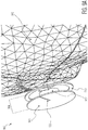
Figure 9A is a fifth exampleconductive plane antenna 900. The fifth exampleconductive plane antenna 900 shows auser 902 wearing aheadphone 904. Theheadphone 904 includes aconductive plane 906 having anopen cavity 908, and a conducting (e.g. metal) reflector 910 (e.g. a conductive ring). In this example embodiment, thereflector 910 is part of (e.g. an outer rim of) a loudspeaker structure having a centerelectromagnetic coil 912. - The
reflector 910 is on one side of theconductive plane 906. Thereflector 910 is configured to redirects any energy radiated from theconductive plane 906 toward theuser 902 back away from theuser 902 so as to enhance radiation away from the user's 902 head and toward any other wireless device with which communication is desired. - In one example embodiment, the resultant increase in
antenna 900 gain can be roughly 6 dB, which about doubles the antenna's 900 communication range. - In some example embodiments, the
reflector 910 also includes a non-conductive cavity, which is aligned with theopen cavity 908 in theconductive plane 906. For example, if the spacing between thereflector 910 and theconductive plane 906 withslot 908 is sufficiently large, there does not need to be a non-conductive cavity in 910. However, if 910 and 906 are close to each other, a 910 reflector with a cavity can yield a better antenna gain pattern. -
Antenna 900 input impedance minimally affected so that impedance matching with various electronic components/circuits is still excellent. -
Figure 9B is an example simulated 3dimensional radiation pattern 914 for the fifth exampleconductive plane antenna 900 ofFigure 9A . Shown is theuser 902, theheadphone 904, and anexample antenna gain 916. - Example discloses a conductive plane antenna, including, a non-conductive substrate; a conductive plane coupled to the non-conductive substrate; wherein the conductive plane includes an open cavity over the non-conductive substrate; wherein the cavity includes a closed end and an open end; a first feed point coupled to the conductive plane and configured to pass a first polarity of a set of electromagnetic signals; and a second feed point coupled to the conductive plane and configured to pass a second polarity of the set of electromagnetic signals wherein the conductive plane is configured to generate a first antenna gain pattern in response to the first and second polarity signals; wherein the cavity is configured to generate a second antenna gain pattern in response to the first and second polarity signals; and wherein a magnitude of the first antenna gain pattern is greater than a magnitude of the second antenna gain pattern.
- It will be readily understood that the components of the embodiments as generally described herein and illustrated in the appended Figures could be arranged and designed in a wide variety of different configurations. Thus, the detailed description of various embodiments, as represented in the Figures, is not intended to limit the scope of the present disclosure, but is merely representative of various embodiments. While the various aspects of the embodiments are presented in drawings, the drawings are not necessarily drawn to scale unless specifically indicated.
- The present invention may be embodied in other specific forms without departing from its spirit or essential characteristics. The described embodiments are to be considered in all respects only as illustrative and not restrictive. The scope of the invention is, therefore, indicated by the appended claims rather than by this detailed description. All changes which come within the meaning and range of equivalency of the claims are to be embraced within their scope.
- Reference throughout this specification to features, advantages, or similar language does not imply that all of the features and advantages that may be realized with the present invention should be or are in any single embodiment of the invention. Rather, language referring to the features and advantages is understood to mean that a specific feature, advantage, or characteristic described in connection with an embodiment is included in at least one embodiment of the present invention. Thus, discussions of the features and advantages, and similar language, throughout this specification may, but do not necessarily, refer to the same embodiment.
- Furthermore, the described features, advantages, and characteristics of the invention may be combined in any suitable manner in one or more embodiments. One skilled in the relevant art will recognize, in light of the description herein, that the invention can be practiced without one or more of the specific features or advantages of a particular embodiment. In other instances, additional features and advantages may be recognized in certain embodiments that may not be present in all embodiments of the invention.
- Reference throughout this specification to "one embodiment," "an embodiment," or similar language means that a particular feature, structure, or characteristic described in connection with the indicated embodiment is included in at least one embodiment of the present invention. Thus, the phrases "in one embodiment," "in an embodiment," and similar language throughout this specification may, but do not necessarily, all refer to the same embodiment.
Claims (15)
- A conductive plane antenna, comprising:a non-conductive substrate;a conductive plane coupled to the non-conductive substrate;wherein the conductive plane includes an open cavity over the non-conductive substrate;wherein the cavity includes a closed end and an open end;a first feed point coupled to the conductive plane and configured to pass a first polarity of a set of electromagnetic signals; anda second feed point coupled to the conductive plane and configured to pass a second polarity of the set of electromagnetic signals;wherein the conductive plane is configured to generate a first antenna gain pattern in response to the first and second polarity signals;wherein the cavity is configured to generate a second antenna gain pattern in response to the first and second polarity signals; andwherein a magnitude of the first antenna gain pattern is greater than a magnitude of the second antenna gain pattern.
- The antenna of claim 1:wherein the cavity further includes a first edge and a second edge; andwherein the cavity is positioned within the conductive plane such that a first current distribution on the first edge of the cavity is opposite to a second current distribution on the second edge of the cavity.
- The antenna of claim 2:
wherein a polarity of the first current distribution at the first edge is opposite to a polarity of the second current distribution on the second edge of the cavity. - The antenna of claim 2 or 3:
wherein a magnitude of the first current distribution at the first edge is substantially equal to a magnitude of the second current distribution on the second edge of the cavity. - The antenna of any preceding claim:wherein the cavity further includes a first edge and a second edge; andwherein the cavity is positioned within the conductive plane such that a first current distribution on the first edge of the cavity substantially cancels out a second current distribution on the second edge of the cavity.
- The antenna of any preceding claim:
wherein the first and second feed points are located closer to the closed end of the cavity than the open end. - The antenna of any preceding claim:
wherein the conductive plane is connected to at least one of: a ground potential, a power supply potential, or an intermediate circuit potential. - The antenna of any preceding claim:
wherein the conductive plane includes an outer edge having a physical or electrical length of at least one-half wavelength of a lowest in-band frequency in the set of electromagnetic signals. - The antenna of any preceding claim:
wherein the open cavity includes a depth having a physical or electrical length at least one-quarter wavelength of a lowest in-band frequency in the set of electromagnetic signals. - The antenna of any preceding claim:
wherein, excluding the open cavity, the conductive plane includes an outer edge which is continuously curved. - The antenna of any preceding claim:wherein the conductive plane includes an outer edge; andwherein the outer edge is defined by an envelope that is either circular or oval in shape.
- The antenna of any preceding claim:
wherein the closed end of the open cavity is located proximate to a geometrical center of the conductive plane. - The antenna of any preceding claim:
further comprising a conducting reflector on one side of the conductive plane. - The antenna of claim 13:
wherein the conducting reflector is a loudspeaker. - The antenna of claim 13 or 14:
wherein the reflector includes a non-conductive cavity aligned with the open cavity in the conductive plane.
Applications Claiming Priority (1)
| Application Number | Priority Date | Filing Date | Title |
|---|---|---|---|
| US15/873,050 US10763584B2 (en) | 2018-01-17 | 2018-01-17 | Conductive plane antenna |
Publications (2)
| Publication Number | Publication Date |
|---|---|
| EP3514886A1 true EP3514886A1 (en) | 2019-07-24 |
| EP3514886B1 EP3514886B1 (en) | 2024-03-13 |
Family
ID=65010566
Family Applications (1)
| Application Number | Title | Priority Date | Filing Date |
|---|---|---|---|
| EP19150669.0A Active EP3514886B1 (en) | 2018-01-17 | 2019-01-08 | Conductive plane antenna |
Country Status (3)
| Country | Link |
|---|---|
| US (1) | US10763584B2 (en) |
| EP (1) | EP3514886B1 (en) |
| CN (1) | CN110048213A (en) |
Cited By (1)
| Publication number | Priority date | Publication date | Assignee | Title |
|---|---|---|---|---|
| WO2021050482A1 (en) * | 2019-09-10 | 2021-03-18 | Bose Corporation | Multi-band slot antenna |
Citations (3)
| Publication number | Priority date | Publication date | Assignee | Title |
|---|---|---|---|---|
| EP1906487A1 (en) * | 2006-09-29 | 2008-04-02 | Alps Electric Co., Ltd. | Antenna structure having stable properties and headset |
| US20100207829A1 (en) * | 2009-02-18 | 2010-08-19 | Harris Corporation | Planar slot antenna having multi-polarization capability and associated methods |
| US20120120772A1 (en) * | 2010-11-12 | 2012-05-17 | Seiko Epson Corporation | Electronic Timepiece with Internal Antenna |
Family Cites Families (7)
| Publication number | Priority date | Publication date | Assignee | Title |
|---|---|---|---|---|
| GB2235590B (en) | 1989-08-21 | 1994-05-25 | Radial Antenna Lab Ltd | Planar antenna |
| US5216430A (en) * | 1990-12-27 | 1993-06-01 | General Electric Company | Low impedance printed circuit radiating element |
| US6646618B2 (en) | 2001-04-10 | 2003-11-11 | Hrl Laboratories, Llc | Low-profile slot antenna for vehicular communications and methods of making and designing same |
| US7388550B2 (en) * | 2005-10-11 | 2008-06-17 | Tdk Corporation | PxM antenna with improved radiation characteristics over a broad frequency range |
| US8912966B2 (en) | 2007-10-19 | 2014-12-16 | Nxp, B.V. | Dual band slot antenna |
| CN101931126A (en) | 2009-06-18 | 2010-12-29 | 鸿富锦精密工业(深圳)有限公司 | Slot antenna |
| US9825357B2 (en) * | 2015-03-06 | 2017-11-21 | Harris Corporation | Electronic device including patch antenna assembly having capacitive feed points and spaced apart conductive shielding vias and related methods |
-
2018
- 2018-01-17 US US15/873,050 patent/US10763584B2/en active Active
-
2019
- 2019-01-08 EP EP19150669.0A patent/EP3514886B1/en active Active
- 2019-01-11 CN CN201910030149.7A patent/CN110048213A/en active Pending
Patent Citations (3)
| Publication number | Priority date | Publication date | Assignee | Title |
|---|---|---|---|---|
| EP1906487A1 (en) * | 2006-09-29 | 2008-04-02 | Alps Electric Co., Ltd. | Antenna structure having stable properties and headset |
| US20100207829A1 (en) * | 2009-02-18 | 2010-08-19 | Harris Corporation | Planar slot antenna having multi-polarization capability and associated methods |
| US20120120772A1 (en) * | 2010-11-12 | 2012-05-17 | Seiko Epson Corporation | Electronic Timepiece with Internal Antenna |
Cited By (2)
| Publication number | Priority date | Publication date | Assignee | Title |
|---|---|---|---|---|
| WO2021050482A1 (en) * | 2019-09-10 | 2021-03-18 | Bose Corporation | Multi-band slot antenna |
| US11362428B2 (en) | 2019-09-10 | 2022-06-14 | Bose Corporation | Multi-band slot antenna |
Also Published As
| Publication number | Publication date |
|---|---|
| US10763584B2 (en) | 2020-09-01 |
| US20190221946A1 (en) | 2019-07-18 |
| CN110048213A (en) | 2019-07-23 |
| EP3514886B1 (en) | 2024-03-13 |
Similar Documents
| Publication | Publication Date | Title |
|---|---|---|
| US9432779B2 (en) | Hearing aid antenna | |
| JP6449352B2 (en) | Compound loop antenna | |
| JP4456588B2 (en) | Antenna structure and headset | |
| US7911405B2 (en) | Multi-band low profile antenna with low band differential mode | |
| US9236656B2 (en) | Radio frequency antenna circuit | |
| US20090231211A1 (en) | Antenna for use in earphone and earphone with integrated antenna | |
| US20060017620A1 (en) | Ultra-wide band meanderline fed monopole antenna | |
| WO2021238347A1 (en) | Antenna and electronic device | |
| JP2003087043A (en) | Antenna device | |
| CN112397897B (en) | Wireless transceiver device, antenna unit and base station | |
| EP3514886B1 (en) | Conductive plane antenna | |
| TW201242167A (en) | Handheld device and radiation pattern adjustment method | |
| CN102157794B (en) | Three-frequency band antenna produced by resonating | |
| CN108574136B (en) | Wireless device antenna | |
| JP4105728B2 (en) | Wideband monopole antenna assembly | |
| WO2023273786A1 (en) | Wearable device | |
| CN217011144U (en) | Wireless earphone | |
| CN218734840U (en) | Wireless earphone and double-ear-real wireless earphone | |
| CN218569225U (en) | Ultra-wideband antenna and communication equipment | |
| KR102158981B1 (en) | Antenna with a symmetrical Feeder Circuit for Improving Antenna Pattern | |
| KR101519158B1 (en) | A antenna apparatus of wireless terminal | |
| US20230076815A1 (en) | Antenna apparatus | |
| WO2024055868A1 (en) | Wearable device | |
| CN115361627A (en) | Wireless earphone and double-ear real wireless earphone | |
| CN114464986A (en) | Head-mounted device |
Legal Events
| Date | Code | Title | Description |
|---|---|---|---|
| PUAI | Public reference made under article 153(3) epc to a published international application that has entered the european phase |
Free format text: ORIGINAL CODE: 0009012 |
|
| STAA | Information on the status of an ep patent application or granted ep patent |
Free format text: STATUS: THE APPLICATION HAS BEEN PUBLISHED |
|
| AK | Designated contracting states |
Kind code of ref document: A1 Designated state(s): AL AT BE BG CH CY CZ DE DK EE ES FI FR GB GR HR HU IE IS IT LI LT LU LV MC MK MT NL NO PL PT RO RS SE SI SK SM TR |
|
| AX | Request for extension of the european patent |
Extension state: BA ME |
|
| STAA | Information on the status of an ep patent application or granted ep patent |
Free format text: STATUS: REQUEST FOR EXAMINATION WAS MADE |
|
| 17P | Request for examination filed |
Effective date: 20200124 |
|
| RBV | Designated contracting states (corrected) |
Designated state(s): AL AT BE BG CH CY CZ DE DK EE ES FI FR GB GR HR HU IE IS IT LI LT LU LV MC MK MT NL NO PL PT RO RS SE SI SK SM TR |
|
| STAA | Information on the status of an ep patent application or granted ep patent |
Free format text: STATUS: EXAMINATION IS IN PROGRESS |
|
| 17Q | First examination report despatched |
Effective date: 20211022 |
|
| REG | Reference to a national code |
Ref country code: DE Ref legal event code: R079 Ref document number: 602019048078 Country of ref document: DE Free format text: PREVIOUS MAIN CLASS: H01Q0001220000 Ipc: H01Q0001270000 Ref country code: DE Ref legal event code: R079 Free format text: PREVIOUS MAIN CLASS: H01Q0001220000 Ipc: H01Q0001270000 |
|
| RIC1 | Information provided on ipc code assigned before grant |
Ipc: H01Q 1/22 20060101ALI20230808BHEP Ipc: H01Q 1/38 20060101ALI20230808BHEP Ipc: H01Q 7/00 20060101ALI20230808BHEP Ipc: H01Q 1/27 20060101AFI20230808BHEP |
|
| GRAP | Despatch of communication of intention to grant a patent |
Free format text: ORIGINAL CODE: EPIDOSNIGR1 |
|
| STAA | Information on the status of an ep patent application or granted ep patent |
Free format text: STATUS: GRANT OF PATENT IS INTENDED |
|
| INTG | Intention to grant announced |
Effective date: 20230915 |
|
| GRAS | Grant fee paid |
Free format text: ORIGINAL CODE: EPIDOSNIGR3 |
|
| GRAA | (expected) grant |
Free format text: ORIGINAL CODE: 0009210 |
|
| STAA | Information on the status of an ep patent application or granted ep patent |
Free format text: STATUS: THE PATENT HAS BEEN GRANTED |
|
| AK | Designated contracting states |
Kind code of ref document: B1 Designated state(s): AL AT BE BG CH CY CZ DE DK EE ES FI FR GB GR HR HU IE IS IT LI LT LU LV MC MK MT NL NO PL PT RO RS SE SI SK SM TR |
|
| REG | Reference to a national code |
Ref country code: GB Ref legal event code: FG4D |
|
| REG | Reference to a national code |
Ref country code: CH Ref legal event code: EP |
|
| REG | Reference to a national code |
Ref country code: DE Ref legal event code: R096 Ref document number: 602019048078 Country of ref document: DE |