EP3514877A1 - Electrode assembly and manufacturing method for electrode assembly - Google Patents
Electrode assembly and manufacturing method for electrode assembly Download PDFInfo
- Publication number
- EP3514877A1 EP3514877A1 EP18806148.5A EP18806148A EP3514877A1 EP 3514877 A1 EP3514877 A1 EP 3514877A1 EP 18806148 A EP18806148 A EP 18806148A EP 3514877 A1 EP3514877 A1 EP 3514877A1
- Authority
- EP
- European Patent Office
- Prior art keywords
- electrode
- separator member
- full length
- side separator
- electrode assembly
- Prior art date
- Legal status (The legal status is an assumption and is not a legal conclusion. Google has not performed a legal analysis and makes no representation as to the accuracy of the status listed.)
- Granted
Links
Images




Classifications
-
- H—ELECTRICITY
- H01—ELECTRIC ELEMENTS
- H01M—PROCESSES OR MEANS, e.g. BATTERIES, FOR THE DIRECT CONVERSION OF CHEMICAL ENERGY INTO ELECTRICAL ENERGY
- H01M10/00—Secondary cells; Manufacture thereof
- H01M10/04—Construction or manufacture in general
- H01M10/0459—Cells or batteries with folded separator between plate-like electrodes
-
- H—ELECTRICITY
- H01—ELECTRIC ELEMENTS
- H01M—PROCESSES OR MEANS, e.g. BATTERIES, FOR THE DIRECT CONVERSION OF CHEMICAL ENERGY INTO ELECTRICAL ENERGY
- H01M10/00—Secondary cells; Manufacture thereof
- H01M10/04—Construction or manufacture in general
-
- H—ELECTRICITY
- H01—ELECTRIC ELEMENTS
- H01M—PROCESSES OR MEANS, e.g. BATTERIES, FOR THE DIRECT CONVERSION OF CHEMICAL ENERGY INTO ELECTRICAL ENERGY
- H01M10/00—Secondary cells; Manufacture thereof
- H01M10/04—Construction or manufacture in general
- H01M10/0436—Small-sized flat cells or batteries for portable equipment
-
- H—ELECTRICITY
- H01—ELECTRIC ELEMENTS
- H01M—PROCESSES OR MEANS, e.g. BATTERIES, FOR THE DIRECT CONVERSION OF CHEMICAL ENERGY INTO ELECTRICAL ENERGY
- H01M10/00—Secondary cells; Manufacture thereof
- H01M10/05—Accumulators with non-aqueous electrolyte
- H01M10/058—Construction or manufacture
- H01M10/0583—Construction or manufacture of accumulators with folded construction elements except wound ones, i.e. folded positive or negative electrodes or separators, e.g. with "Z"-shaped electrodes or separators
-
- H—ELECTRICITY
- H01—ELECTRIC ELEMENTS
- H01M—PROCESSES OR MEANS, e.g. BATTERIES, FOR THE DIRECT CONVERSION OF CHEMICAL ENERGY INTO ELECTRICAL ENERGY
- H01M50/00—Constructional details or processes of manufacture of the non-active parts of electrochemical cells other than fuel cells, e.g. hybrid cells
- H01M50/40—Separators; Membranes; Diaphragms; Spacing elements inside cells
- H01M50/46—Separators, membranes or diaphragms characterised by their combination with electrodes
-
- H—ELECTRICITY
- H01—ELECTRIC ELEMENTS
- H01M—PROCESSES OR MEANS, e.g. BATTERIES, FOR THE DIRECT CONVERSION OF CHEMICAL ENERGY INTO ELECTRICAL ENERGY
- H01M50/00—Constructional details or processes of manufacture of the non-active parts of electrochemical cells other than fuel cells, e.g. hybrid cells
- H01M50/50—Current conducting connections for cells or batteries
- H01M50/531—Electrode connections inside a battery casing
-
- H—ELECTRICITY
- H01—ELECTRIC ELEMENTS
- H01M—PROCESSES OR MEANS, e.g. BATTERIES, FOR THE DIRECT CONVERSION OF CHEMICAL ENERGY INTO ELECTRICAL ENERGY
- H01M50/00—Constructional details or processes of manufacture of the non-active parts of electrochemical cells other than fuel cells, e.g. hybrid cells
- H01M50/50—Current conducting connections for cells or batteries
- H01M50/531—Electrode connections inside a battery casing
- H01M50/538—Connection of several leads or tabs of wound or folded electrode stacks
-
- Y—GENERAL TAGGING OF NEW TECHNOLOGICAL DEVELOPMENTS; GENERAL TAGGING OF CROSS-SECTIONAL TECHNOLOGIES SPANNING OVER SEVERAL SECTIONS OF THE IPC; TECHNICAL SUBJECTS COVERED BY FORMER USPC CROSS-REFERENCE ART COLLECTIONS [XRACs] AND DIGESTS
- Y02—TECHNOLOGIES OR APPLICATIONS FOR MITIGATION OR ADAPTATION AGAINST CLIMATE CHANGE
- Y02E—REDUCTION OF GREENHOUSE GAS [GHG] EMISSIONS, RELATED TO ENERGY GENERATION, TRANSMISSION OR DISTRIBUTION
- Y02E60/00—Enabling technologies; Technologies with a potential or indirect contribution to GHG emissions mitigation
- Y02E60/10—Energy storage using batteries
-
- Y—GENERAL TAGGING OF NEW TECHNOLOGICAL DEVELOPMENTS; GENERAL TAGGING OF CROSS-SECTIONAL TECHNOLOGIES SPANNING OVER SEVERAL SECTIONS OF THE IPC; TECHNICAL SUBJECTS COVERED BY FORMER USPC CROSS-REFERENCE ART COLLECTIONS [XRACs] AND DIGESTS
- Y02—TECHNOLOGIES OR APPLICATIONS FOR MITIGATION OR ADAPTATION AGAINST CLIMATE CHANGE
- Y02P—CLIMATE CHANGE MITIGATION TECHNOLOGIES IN THE PRODUCTION OR PROCESSING OF GOODS
- Y02P70/00—Climate change mitigation technologies in the production process for final industrial or consumer products
- Y02P70/50—Manufacturing or production processes characterised by the final manufactured product
Definitions
- the present invention relates to an electrode assembly and a method for manufacturing the same, and more particularly, to an electrode assembly in which a plurality of electrode units are stacked to improve product stability when manufactured and a method for manufacturing the same.
- Batteries (cells) that generate electric energy through physical or chemical reaction to supply the generated electric energy to the outside are used when AC power to be supplied to the building is not obtained, or DC power is required according to the living environments surrounded by various electric and electronic devices.
- primary batteries and secondary batteries which are chemical batteries using chemical reaction, are being generally used.
- the primary batteries are consumable batteries which are collectively referred to as dry batteries.
- secondary batteries are rechargeable batteries that are manufactured by using a material in a redox process between current and a substance is repeatable several times. When the reduction reaction is performed on the material by the current, power is charged, and when the oxidation reaction is performed on the material, power is discharged. Such the charging-discharging is repeatedly performed to generate electricity.
- a stacking-type lithium secondary battery including a different electrode active material layer is disclosed in Korean Patent Publication No. 10-2006-0122344 .
- a folding cell in which a plurality of electrode stacks are stacked is manufactured.
- the pouch-type battery has a problem in that applied tension is low in a full length direction (a direction in which an electrode tab is formed) when compared with a full width direction because the pouch-type battery takes a manner in which winding and folding are performed in the full width direction (a direction perpendicular to the electrode tab) of the electrode stack.
- the upper end of the electrode stack may increase in resistance due to the above problems to generate a lithium-plating. Also, since it is difficult to seal the upper end, there is a disadvantage in thermal stability evaluation item such as heating.
- the present invention has been made in order to solve the above problem, and thus an object of the present invention is to provide an electrode, which gradually increases in height of a stepped portion between an electrode active material layer and a non-coating portion to stably wind the electrode without an occurrence of folding of the stepped portion between the electrode active material layer and the non-coating portion when the electrode is wound around the core part, thereby preventing the cracks from occurring, and a secondary battery comprising the same.
- an object of the prevent invention is to provide an electrode assembly that is capable of securing safety of an electrode unit and a method for manufacturing the electrode assembly.
- An electrode assembly includes a plurality of electrode units on which electrode tabs are formed and a full length-side separator member folded in a direction in which the electrode tabs are formed and a direction opposite to the direction in which the electrode tabs are formed while stacking the plurality of electrode units to be separated from each other.
- the full length-side separator member may include a folding part that is folded at a portion corresponding to each of the electrode tabs.
- the full length-side separator member may include a tab hole that is punched to allow the electrode tab to pass therethrough.
- the electrode assembly may further include a full width-side separator member extending from the full length-side separator member and formed in a direction perpendicular to the full length-side separator member.
- the full width-side separator member may be folded in a direction perpendicular to the direction in which the electrode tab is formed while electrode units stacked to follow the plurality of electrode units are stacked to be separated from each other.
- the full width-side separator member may be formed on at least one or more ends of the full length-side separator member.
- the full width-side separator member may be formed in a length of the full length-side separator member.
- the whole of the electrode unit except for the electrode tab may be covered by the full length-side separator member and the full width-side separator member.
- the electrode unit may be a unit assembly having a shape in which a separator is stacked between a positive electrode and a negative electrode.
- a method for manufacturing an electrode assembly includes a preparation step of preparing a plurality of electrode units on which electrode tabs are formed and a full length-side stacking step of folding a full length-side separator member in a direction in which the electrode tab of each of the electrode units is formed and a direction opposite to the direction in which the electrode tab is formed so as to be stacked so that the plurality of electrode units are separated from each other.
- the method may further include, after the full length-side stacking step, a full width-side stacking step of folding a full width-side separator member in a direction perpendicular to the direction in which the electrode tab is formed so as to be stacked so that electrode units stacked to follow the plurality of electrode units in succession to the full length-side stacking step are separated from each other.
- the safety of the upper end of the electrode unit may be secured.
- the safety of the lower end of the electrode unit may be secured.
- the safety during the drop test may be secured.
- the safety in the thermal safety evaluation items may be secured.
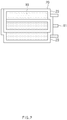
- FIG. 1 is a development view of an electrode assembly according to an embodiment of the present invention
- FIG. 2 is a side view illustrating a state in which the electrode assembly of FIG. 1 is folded to be stacked.
- an electrode assembly includes a plurality of electrode units 10 on which electrode tabs 11 are formed and a full length-side separator member 20 that is folded in a direction in which the electrode tab 11 is formed and a direction opposite to the direction in which the electrode tab 11 is formed while stacking the plurality of electrode units 10 to be separated from each other.
- each of the electrode units 10 may be a unit assembly having the form of a bicell of positive electrode (negative electrode)/separator/negative electrode (positive electrode)/separator/positive electrode (negative electrode).
- the electrode unit 10 may have the form of a full cell of positive electrode/separator/negative electrode.
- the electrode unit 10 may be a single electrode such as a negative electrode or a positive electrode.
- the full length-side separator member 20 may include a folding part 21 that is folded at a portion corresponding to the electrode tab 11 of the electrode unit 10.
- the full length-side separator member 20 may include a tab hole 23, which is punched to allow the electrode tab 11 to pass therethrough, in the folding part 21.
- the tab hole 23 may be formed by punching a portion, at which the electrode tab 11 needs to be penetrated, in the full length-side separator member 20 in addition to the folding part 21.
- the full length-side separator member 20 may cover the electrode unit 10 in a full length direction L.
- the full length-side separator member 20 may cover all portions except for the electrode tab 11 in the full length direction L.
- the gas may be discharged through the tab hole 23.
- the separator is folded toward the full length side of the electrode unit 10, i.e., the side, at which the electrode tab 11 is formed, to stack the electrode units 10, bonding force between the electrode and the separator may increase at the portion at which the sealing is difficult, and the electrode tab 11 is formed.
- the portion, at which the electrode tab 11 of the electrode unit 10 is formed may be reduced in resistance to prevent a lithium-plating from being formed and secure stability in thermal safety evaluation such as heating.
- the separator member since the separator member is folded in only a full width direction W, the tension is low in the full length direction. Thus, the electrode and the separator are relatively loosened in the full length direction L. As a result, the lithium-plating may be well formed to deteriorate the thermal safety evaluation.
- the full length-side separator member 20 may be folded to an opposite side of the portion, at which the electrode tab 11 of the electrode unit 10 is formed, to secure the bonding force between the separator and the electrode unit 10, thereby securing the safety in the evaluation such as dropping.
- the full length-side separator member 20 since the full length-side separator member 20 is folded in only the full width direction W, an end of the separator may be sealed to the electrode tab formation portion to prevent the separator from being separated from the formation portion of the electrode tab 11 in the full length direction.
- the separation of the separator since the end of the electrode is covered by thee separator member in the full width direction W, the separation of the separator may be prevented without performing the sealing.
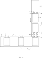
- FIG. 3 is a development view of an electrode assembly according to another embodiment of the present invention
- FIG. 4 is a front view illustrating a state in which the electrode assembly of FIG. 3 is folded to be stacked
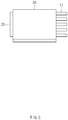
- FIG. 5 is a side view of FIG. 4 .
- an electrode assembly according to another embodiment of the present invention may further include a full width-side separator member 30 extending from a full length-side separator member 20 and formed in a direction perpendicular to the full length-side separator member 20.
- the full width-side separator member 30 may extend perpendicular to at least one or more ends of the full length-side separator member 20.
- FIG. 6 is a development view illustrating an electrode assembly according to further another embodiment of the present invention
- FIG. 7 is a side view illustrating a state in which the electrode assembly of FIG. 6 is folded to be stacked.
- a full width-side separator member 30 may be formed in a length of a full length-side separator member 20.
- the full width-side separator member 30 may be folded toward the plurality of electrode units 10 stacked on the full length-side separator member 20 to stack electrode units 10a to be separated from each other, which are stacked to follow the plurality of electrode units 10.
- the separator member 20 is folded first, and then, the separator member 30 is folded again in the full width direction W to stack the electrode units, thereby manufacturing the electrode assembly.
- the electrode unit 10a may be folded in a direction perpendicular to a direction in which an electrode tab 11 is formed.
- the electrode unit 10 is covered toward the full length side by the full length-side separator member 20 and covered toward the full width side by the full width-side separator member 30 to cover all four surfaces of the electrode unit 10 except for the electrode tab 11.
- the separator since the whole of the electrode unit 10 except for the electrode tab 11 is covered by the separator, bonding between the electrode unit 10 and the separator may be strongly maintained at even a portion, which is adjacent to the electrode tab 11 that is difficult to be sealed, in the electrode unit 10 to prevent a lithium-plating from occurring and improve safety in the thermal safety evaluation such as the heating.
- the bonding between the electrode unit 10 and the separator may also be strongly maintained at a portion that is opposite to the formation portion of the electrode tab 11 in the electrode unit 10 to secure the safety in drop evaluation.
- the electrode assembly according to the present invention may have an effect occurring when the four surfaces of the electrode unit are completely covered by the separator.
- the four edge surfaces of the electrode unit may not be closed by thermal fusion or bonding processing but be covered by the separator member. Thus, damage occurring due to the thermal fusion processing or the bonding processing may be prevented.
- the separators of the full length-side separator member 20 and the full width-side separator member 30 according to an embodiment of the present invention may be manufactured, for example, by applying a polyvinylidene fluoride-hexafluoropropylene copolymer (PVDF-HFP co-polymer) to one base material selected from the group consisting of, for example, polyethylene (PE), polystyrene (PS), polypropylene (PP), and a copolymer of polyethylene (PE) and polypropylene.
- PVDF-HFP co-polymer polyvinylidene fluoride-hexafluoropropylene copolymer
- FIG. 8 is a flowchart sequentially illustrating a method for manufacturing an electrode assembly according to an embodiment of the present invention.
- a method for manufacturing an electrode assembly includes a preparation step (S1) and a stacking step (S2).
- the preparation step (S1) is a step of preparing a plurality of electrode units 10 on which electrode tabs 11 are formed.
- a full length-side stacking step (S2) may include a step of placing the plurality of electrode units 10 on a full length-side separator member 20.
- the full length-side stacking step (S2) is a step of folding the full length-side separator member 20 in a direction in which the electrode tab 11 of the electrode unit 10 is formed and a direction opposite to the direction in which the electrode tab 11 is formed to stack the plurality of electrode units 10.
- the electrode tab 11 may pass through a tab hole 23 that is punched in the full length-side separator member 20.
- a full width-side stacking step in which electrode units 10a stacked to follow the plurality of electrode units 10 stacked on the full length-side separator member 20 in succession to the full length-side stacking step (S2) are stacked to be separated from each other may be further performed.
- the electrode units 10a are placed on the full width-side separator member 30 and then folded in a direction perpendicular to the direction in which the electrode tabs 11 of the electrode units 10a are formed to stack the electrode units 10a.
- the upper end of the electrode unit may be secured in safety, and the lower end of the electrode unit may be secured in safety.
- the safety may be secured during the drop test, and the safety in thermal safety evaluation item may be secured.
Landscapes
- Chemical & Material Sciences (AREA)
- Chemical Kinetics & Catalysis (AREA)
- Electrochemistry (AREA)
- General Chemical & Material Sciences (AREA)
- Engineering & Computer Science (AREA)
- Manufacturing & Machinery (AREA)
- Secondary Cells (AREA)
- Connection Of Batteries Or Terminals (AREA)
Abstract
Description
- This application claims the priority of Korean Patent Application No.
10-2017-0064898 filed on May 25, 2017 - The present invention relates to an electrode assembly and a method for manufacturing the same, and more particularly, to an electrode assembly in which a plurality of electrode units are stacked to improve product stability when manufactured and a method for manufacturing the same.
- Batteries (cells) that generate electric energy through physical or chemical reaction to supply the generated electric energy to the outside are used when AC power to be supplied to the building is not obtained, or DC power is required according to the living environments surrounded by various electric and electronic devices.
- Among such batteries, primary batteries and secondary batteries, which are chemical batteries using chemical reaction, are being generally used. The primary batteries are consumable batteries which are collectively referred to as dry batteries.
- Also, secondary batteries are rechargeable batteries that are manufactured by using a material in a redox process between current and a substance is repeatable several times. When the reduction reaction is performed on the material by the current, power is charged, and when the oxidation reaction is performed on the material, power is discharged. Such the charging-discharging is repeatedly performed to generate electricity.
- A stacking-type lithium secondary battery including a different electrode active material layer is disclosed in Korean Patent Publication No.
10-2006-0122344 - In the lithium secondary battery according to the related art, a folding cell in which a plurality of electrode stacks are stacked is manufactured.
- However, the pouch-type battery has a problem in that applied tension is low in a full length direction (a direction in which an electrode tab is formed) when compared with a full width direction because the pouch-type battery takes a manner in which winding and folding are performed in the full width direction (a direction perpendicular to the electrode tab) of the electrode stack.
- Also, there is a problem in which bonding force between a separator and an electrode is low because an upper end of the electrode stack, on which positive/negative electrode tabs are disposed, is relatively loosely bonded to an electrode unit such as a bicell or the like.
- The upper end of the electrode stack may increase in resistance due to the above problems to generate a lithium-plating. Also, since it is difficult to seal the upper end, there is a disadvantage in thermal stability evaluation item such as heating.
- The present invention has been made in order to solve the above problem, and thus an object of the present invention is to provide an electrode, which gradually increases in height of a stepped portion between an electrode active material layer and a non-coating portion to stably wind the electrode without an occurrence of folding of the stepped portion between the electrode active material layer and the non-coating portion when the electrode is wound around the core part, thereby preventing the cracks from occurring, and a secondary battery comprising the same.
- Therefore, the present invention has been made to solve the abovementioned problem, and an object of the prevent invention is to provide an electrode assembly that is capable of securing safety of an electrode unit and a method for manufacturing the electrode assembly.
- An electrode assembly according to an embodiment of the present invention includes a plurality of electrode units on which electrode tabs are formed and a full length-side separator member folded in a direction in which the electrode tabs are formed and a direction opposite to the direction in which the electrode tabs are formed while stacking the plurality of electrode units to be separated from each other.
- The full length-side separator member may include a folding part that is folded at a portion corresponding to each of the electrode tabs.
- The full length-side separator member may include a tab hole that is punched to allow the electrode tab to pass therethrough.
- The electrode assembly may further include a full width-side separator member extending from the full length-side separator member and formed in a direction perpendicular to the full length-side separator member.
- The full width-side separator member may be folded in a direction perpendicular to the direction in which the electrode tab is formed while electrode units stacked to follow the plurality of electrode units are stacked to be separated from each other.
- The full width-side separator member may be formed on at least one or more ends of the full length-side separator member.
- The full width-side separator member may be formed in a length of the full length-side separator member.
- The whole of the electrode unit except for the electrode tab may be covered by the full length-side separator member and the full width-side separator member.
- The electrode unit may be a unit assembly having a shape in which a separator is stacked between a positive electrode and a negative electrode.
- A method for manufacturing an electrode assembly according to an embodiment of the present invention includes a preparation step of preparing a plurality of electrode units on which electrode tabs are formed and a full length-side stacking step of folding a full length-side separator member in a direction in which the electrode tab of each of the electrode units is formed and a direction opposite to the direction in which the electrode tab is formed so as to be stacked so that the plurality of electrode units are separated from each other.
- The method may further include, after the full length-side stacking step, a full width-side stacking step of folding a full width-side separator member in a direction perpendicular to the direction in which the electrode tab is formed so as to be stacked so that electrode units stacked to follow the plurality of electrode units in succession to the full length-side stacking step are separated from each other.
- According to the present invention, the safety of the upper end of the electrode unit may be secured.
- According to the present invention, the safety of the lower end of the electrode unit may be secured.
- According to the present invention, the safety during the drop test may be secured.
- According to the present invention, the safety in the thermal safety evaluation items may be secured.
-
-
FIG. 1 is a development view of an electrode assembly according to an embodiment of the present invention. -
FIG. 2 is a side view illustrating a state in which the electrode assembly ofFIG. 1 is folded to be stacked. -
FIG. 3 is a development view of an electrode assembly according to another embodiment of the present invention. -
FIG. 4 is a front view illustrating a state in which the electrode assembly ofFIG. 3 is folded to be stacked. -
FIG. 5 is a side view ofFIG. 4 . -
FIG. 6 is a development view illustrating an electrode assembly according to further another embodiment of the present invention. -
FIG. 7 is a side view illustrating a state in which the electrode assembly ofFIG. 6 is folded to be stacked. -
FIG. 8 is a flowchart sequentially illustrating a method for manufacturing an electrode assembly according to an embodiment of the present invention. - Hereinafter, a secondary battery and a method for manufacturing the same according to preferred embodiments of the present invention will be described in detail with reference to the accompanying drawings.
- Terms or words used in the specification and claims should not be construed as limited to a lexical meaning, and should be understood as appropriate notions by the inventor based on that he/she is able to define terms to describe his/her invention in the best way to be seen by others. Therefore, embodiments and drawings described herein are simply exemplary and not exhaustive, and it will be understood that various equivalents may be made to take the place of the embodiments.
- In the drawings, the dimension of each of components or a specific portion constituting the component is exaggerated, omitted, or schematically illustrated for convenience in description and clarity. Thus, the dimension of each element does not entirely reflect an actual size. Moreover, detailed descriptions related to well-known functions or configurations will be ruled out in order not to unnecessarily obscure subject matters of the present invention.
-
FIG. 1 is a development view of an electrode assembly according to an embodiment of the present invention, andFIG. 2 is a side view illustrating a state in which the electrode assembly ofFIG. 1 is folded to be stacked. - As illustrated in
FIGS. 1 and2 , an electrode assembly according to an embodiment of the present invention includes a plurality ofelectrode units 10 on whichelectrode tabs 11 are formed and a full length-side separator member 20 that is folded in a direction in which theelectrode tab 11 is formed and a direction opposite to the direction in which theelectrode tab 11 is formed while stacking the plurality ofelectrode units 10 to be separated from each other. - According to an embodiment, each of the
electrode units 10 may be a unit assembly having the form of a bicell of positive electrode (negative electrode)/separator/negative electrode (positive electrode)/separator/positive electrode (negative electrode). According to another embodiment, theelectrode unit 10 may have the form of a full cell of positive electrode/separator/negative electrode. According to further another embodiment, theelectrode unit 10 may be a single electrode such as a negative electrode or a positive electrode. - The full length-
side separator member 20 may include a foldingpart 21 that is folded at a portion corresponding to theelectrode tab 11 of theelectrode unit 10. - The full length-
side separator member 20 may include atab hole 23, which is punched to allow theelectrode tab 11 to pass therethrough, in thefolding part 21. - Also, the
tab hole 23 may be formed by punching a portion, at which theelectrode tab 11 needs to be penetrated, in the full length-side separator member 20 in addition to the foldingpart 21. - When the folding
part 21 of the full length-side separator member 20 is folded at the portion corresponding to theelectrode tab 11 of theelectrode unit 10, theelectrode tab 11 may pass through thetab hole 23. Thus, the full length-side separator member 20 may cover theelectrode unit 10 in a full length direction L. The full length-side separator member 20 may cover all portions except for theelectrode tab 11 in the full length direction L. - Also, in the state in which the electrode assembly is installed in the secondary battery, when a gas is generated due to reaction between the electrode and an electrolyte, the gas may be discharged through the
tab hole 23. - As described above, since the separator is folded toward the full length side of the
electrode unit 10, i.e., the side, at which theelectrode tab 11 is formed, to stack theelectrode units 10, bonding force between the electrode and the separator may increase at the portion at which the sealing is difficult, and theelectrode tab 11 is formed. - Thus, the portion, at which the
electrode tab 11 of theelectrode unit 10 is formed, may be reduced in resistance to prevent a lithium-plating from being formed and secure stability in thermal safety evaluation such as heating. - That is, according to the related art, since the separator member is folded in only a full width direction W, the tension is low in the full length direction. Thus, the electrode and the separator are relatively loosened in the full length direction L. As a result, the lithium-plating may be well formed to deteriorate the thermal safety evaluation.
- Also, the full length-
side separator member 20 may be folded to an opposite side of the portion, at which theelectrode tab 11 of theelectrode unit 10 is formed, to secure the bonding force between the separator and theelectrode unit 10, thereby securing the safety in the evaluation such as dropping. - Furthermore, according to the related art, since the full length-
side separator member 20 is folded in only the full width direction W, an end of the separator may be sealed to the electrode tab formation portion to prevent the separator from being separated from the formation portion of theelectrode tab 11 in the full length direction. On the other hand, according to the present invention, since the end of the electrode is covered by thee separator member in the full width direction W, the separation of the separator may be prevented without performing the sealing. -
FIG. 3 is a development view of an electrode assembly according to another embodiment of the present invention,FIG. 4 is a front view illustrating a state in which the electrode assembly ofFIG. 3 is folded to be stacked, andFIG. 5 is a side view ofFIG. 4 . - As illustrated in
FIGS. 3 to 5 , an electrode assembly according to another embodiment of the present invention may further include a full width-side separator member 30 extending from a full length-side separator member 20 and formed in a direction perpendicular to the full length-side separator member 20. - The full width-
side separator member 30 may extend perpendicular to at least one or more ends of the full length-side separator member 20. -
FIG. 6 is a development view illustrating an electrode assembly according to further another embodiment of the present invention, andFIG. 7 is a side view illustrating a state in which the electrode assembly ofFIG. 6 is folded to be stacked. - As illustrated in
FIGS. 6 and7 , in an electrode assembly according to further another embodiment of the present invention, a full width-side separator member 30 may be formed in a length of a full length-side separator member 20. - As described above, in the electrode assemblies according to another embodiment and further another embodiment of the present invention, the full width-
side separator member 30 may be folded toward the plurality ofelectrode units 10 stacked on the full length-side separator member 20 to stackelectrode units 10a to be separated from each other, which are stacked to follow the plurality ofelectrode units 10. - Referring to
FIG. 6 , theseparator member 20 is folded first, and then, theseparator member 30 is folded again in the full width direction W to stack the electrode units, thereby manufacturing the electrode assembly. - In this case, the
electrode unit 10a may be folded in a direction perpendicular to a direction in which anelectrode tab 11 is formed. - Thus, the
electrode unit 10 is covered toward the full length side by the full length-side separator member 20 and covered toward the full width side by the full width-side separator member 30 to cover all four surfaces of theelectrode unit 10 except for theelectrode tab 11. - That is, since the whole of the
electrode unit 10 except for theelectrode tab 11 is covered by the separator, bonding between theelectrode unit 10 and the separator may be strongly maintained at even a portion, which is adjacent to theelectrode tab 11 that is difficult to be sealed, in theelectrode unit 10 to prevent a lithium-plating from occurring and improve safety in the thermal safety evaluation such as the heating. - Also, the bonding between the
electrode unit 10 and the separator may also be strongly maintained at a portion that is opposite to the formation portion of theelectrode tab 11 in theelectrode unit 10 to secure the safety in drop evaluation. - Also, the electrode assembly according to the present invention may have an effect occurring when the four surfaces of the electrode unit are completely covered by the separator.
- The four edge surfaces of the electrode unit may not be closed by thermal fusion or bonding processing but be covered by the separator member. Thus, damage occurring due to the thermal fusion processing or the bonding processing may be prevented.
- The separators of the full length-
side separator member 20 and the full width-side separator member 30 according to an embodiment of the present invention may be manufactured, for example, by applying a polyvinylidene fluoride-hexafluoropropylene copolymer (PVDF-HFP co-polymer) to one base material selected from the group consisting of, for example, polyethylene (PE), polystyrene (PS), polypropylene (PP), and a copolymer of polyethylene (PE) and polypropylene. -
FIG. 8 is a flowchart sequentially illustrating a method for manufacturing an electrode assembly according to an embodiment of the present invention. - As illustrated in
FIG. 8 , a method for manufacturing an electrode assembly according to an embodiment of the present invention includes a preparation step (S1) and a stacking step (S2). - The preparation step (S1) is a step of preparing a plurality of
electrode units 10 on whichelectrode tabs 11 are formed. - A full length-side stacking step (S2) may include a step of placing the plurality of
electrode units 10 on a full length-side separator member 20. - In addition, the full length-side stacking step (S2) is a step of folding the full length-
side separator member 20 in a direction in which theelectrode tab 11 of theelectrode unit 10 is formed and a direction opposite to the direction in which theelectrode tab 11 is formed to stack the plurality ofelectrode units 10. - Also, when the full length-
side separator member 20 is folded at the portion on which the electrode tab of theelectrode unit 10 is formed, theelectrode tab 11 may pass through atab hole 23 that is punched in the full length-side separator member 20. - After the full length-side stacking step (S2), a full width-side stacking step in which
electrode units 10a stacked to follow the plurality ofelectrode units 10 stacked on the full length-side separator member 20 in succession to the full length-side stacking step (S2) are stacked to be separated from each other may be further performed. - In the full width-side stacking step, the
electrode units 10a are placed on the full width-side separator member 30 and then folded in a direction perpendicular to the direction in which theelectrode tabs 11 of theelectrode units 10a are formed to stack theelectrode units 10a. - As described above, according to the present invention, the upper end of the electrode unit may be secured in safety, and the lower end of the electrode unit may be secured in safety. In addition, the safety may be secured during the drop test, and the safety in thermal safety evaluation item may be secured.
- Although the electrode assembly and the method for manufacturing the same according to the present invention has been described above with reference to the exemplary drawings, various changes and modifications may be made thereto by one skilled in the art without departing from the scope and spirit of the invention as set forth in the appended claims.
Claims (11)
- An electrode assembly comprising:a plurality of electrode units (10) on which electrode tabs (11) are formed; anda full length-side separator member (20) folded in a direction in which the electrode tabs (11) are formed and a direction opposite to the direction in which the electrode tabs (11) are formed while stacking the plurality of electrode units (10) to be separated from each other.
- The electrode assembly of claim 1, wherein the full length-side separator member (20) comprises a folding part (21) that is folded at a portion corresponding to each of the electrode tabs (11).
- The electrode assembly of claim 2, wherein the full length-side separator member (20) comprises a tab hole (23) that is punched to allow the electrode tab (11) to pass therethrough at the folding part(21).
- The electrode assembly of claim 1, further comprising a full width-side separator member (30) extending from the full length-side separator member (20) and formed in a direction perpendicular to the full length-side separator member (20).
- The electrode assembly of claim 4, wherein the full width-side separator member (30) is folded in a direction perpendicular to the direction in which the electrode tab (11) is formed while electrode units (10a) stacked to follow the plurality of electrode units (10) are stacked to be separated from each other.
- The electrode assembly of claim 4, wherein the full width-side separator member (30) is formed on at least one or more ends of the full length-side separator member (20).
- The electrode assembly of claim 4, wherein the full width-side separator member (30) is formed in a length of the full length-side separator member (20).
- The electrode assembly of claim 4, wherein the whole of the electrode unit (10) except for the electrode tab (11) is covered by the full length-side separator member (20) and the full width-side separator member (30).
- The electrode assembly of any one of claims 1 to 8, wherein the electrode unit (10) is a unit assembly having a shape in which a separator is stacked between a positive electrode and a negative electrode.
- A method for manufacturing an electrode assembly, the method comprising:a preparation step (S1) of preparing a plurality of electrode units (10) on which electrode tabs (11) are formed; anda full length-side stacking step (S2) of folding a full length-side separator member (20) in a direction in which the electrode tab (11) of each of the electrode units (10) is formed and a direction opposite to the direction in which the electrode tab (11) is formed so as to be stacked so that the plurality of electrode units (10) are separated from each other.
- The method of claim 10, further comprising, after the full length-side stacking step (S2), a full width-side stacking step of folding a full width-side separator member (30) in a direction perpendicular to the direction in which the electrode tab (11) is formed so as to be stacked so that electrode units (10a) stacked to follow the plurality of electrode units (10) in succession to the full length-side stacking step (S2) are separated from each other.
Priority Applications (1)
| Application Number | Priority Date | Filing Date | Title |
|---|---|---|---|
| PL18806148T PL3514877T3 (en) | 2017-05-25 | 2018-05-23 | Electrode assembly and manufacturing method for electrode assembly |
Applications Claiming Priority (2)
| Application Number | Priority Date | Filing Date | Title |
|---|---|---|---|
| KR1020170064898A KR102217445B1 (en) | 2017-05-25 | 2017-05-25 | Electrode assembly and manufactureing method for the same |
| PCT/KR2018/005858 WO2018217016A1 (en) | 2017-05-25 | 2018-05-23 | Electrode assembly and manufacturing method for electrode assembly |
Publications (3)
| Publication Number | Publication Date |
|---|---|
| EP3514877A1 true EP3514877A1 (en) | 2019-07-24 |
| EP3514877A4 EP3514877A4 (en) | 2019-09-25 |
| EP3514877B1 EP3514877B1 (en) | 2021-01-13 |
Family
ID=64395767
Family Applications (1)
| Application Number | Title | Priority Date | Filing Date |
|---|---|---|---|
| EP18806148.5A Active EP3514877B1 (en) | 2017-05-25 | 2018-05-23 | Electrode assembly and manufacturing method for electrode assembly |
Country Status (6)
| Country | Link |
|---|---|
| US (1) | US11043691B2 (en) |
| EP (1) | EP3514877B1 (en) |
| KR (1) | KR102217445B1 (en) |
| CN (1) | CN109937502B (en) |
| PL (1) | PL3514877T3 (en) |
| WO (1) | WO2018217016A1 (en) |
Families Citing this family (2)
| Publication number | Priority date | Publication date | Assignee | Title |
|---|---|---|---|---|
| HUE072852T2 (en) | 2019-12-06 | 2025-12-28 | Lg Energy Solution Ltd | Method and apparatus for manufacturing electrode assembly, and method for manufacturing secondary battery including same |
| EP4542717A4 (en) * | 2022-09-27 | 2025-11-19 | Samsung Electronics Co Ltd | BATTERY AND ELECTRONIC DEVICE WITH BATTERY |
Family Cites Families (19)
| Publication number | Priority date | Publication date | Assignee | Title |
|---|---|---|---|---|
| JPH1070052A (en) | 1996-08-28 | 1998-03-10 | Toyota Motor Corp | Electric double layer capacitor |
| US6045943A (en) * | 1997-11-04 | 2000-04-04 | Wilson Greatbatch Ltd. | Electrode assembly for high energy density batteries |
| KR100497147B1 (en) * | 2000-02-08 | 2005-06-29 | 주식회사 엘지화학 | Multiply stacked electrochemical cell and method for preparing the same |
| KR100515572B1 (en) * | 2000-02-08 | 2005-09-20 | 주식회사 엘지화학 | Stacked electrochemical cell and method for preparing the same |
| JP2001291647A (en) | 2000-04-10 | 2001-10-19 | Japan Gore Tex Inc | Multilayer electric double layer capacitors |
| KR100894410B1 (en) | 2005-05-27 | 2009-04-24 | 주식회사 엘지화학 | Superposition Lithium Secondary Battery with Dissimilar Electrode Active Material Layer |
| KR100921347B1 (en) * | 2005-11-08 | 2009-10-14 | 주식회사 엘지화학 | Vertical folding electrode assembly and electrochemical cell containing the same |
| KR101014817B1 (en) | 2007-12-14 | 2011-02-14 | 주식회사 엘지화학 | Stacked / Foldable Electrode Assembly with Safety Member and Method of Manufacturing the Same |
| JP5259453B2 (en) | 2009-02-25 | 2013-08-07 | 富士重工業株式会社 | Electric storage device and manufacturing method thereof |
| KR100960619B1 (en) | 2009-09-30 | 2010-06-07 | 주식회사 이아이지 | Electrode assembly having connection portion of electrode assembly and electrode lead and electrochemical cell containing the same |
| KR101136205B1 (en) * | 2009-11-02 | 2012-04-17 | 삼성에스디아이 주식회사 | Electrode assembly for secondary battery and secondary battery with the electrode assembly |
| KR101152552B1 (en) | 2010-05-04 | 2012-06-01 | 삼성에스디아이 주식회사 | Electrode assembly and secondary battery using the same |
| JP2013530510A (en) * | 2011-06-09 | 2013-07-25 | エルジー ケム. エルティーディ. | Electrode assembly and lithium secondary battery including the same |
| KR101367754B1 (en) | 2011-07-07 | 2014-02-27 | 주식회사 엘지화학 | Electrode assembly for electrochemical device and electrochemical device comprising the same |
| KR101651712B1 (en) | 2012-07-26 | 2016-08-26 | 에스케이이노베이션 주식회사 | Secondary Battery |
| JP2014035998A (en) | 2012-08-10 | 2014-02-24 | Toyota Industries Corp | Power storage device |
| KR101840859B1 (en) * | 2013-11-18 | 2018-03-22 | 주식회사 엘지화학 | Apparatus for Attaching the Adhesion Member for Fixing Battery Assembly |
| JP6583711B2 (en) * | 2015-03-17 | 2019-10-02 | 株式会社Gsユアサ | Electricity storage element |
| CN106099132A (en) * | 2016-08-30 | 2016-11-09 | 惠州市惠德瑞锂电科技股份有限公司 | A kind of lithium battery core body and the lithium primary battery of gained |
-
2017
- 2017-05-25 KR KR1020170064898A patent/KR102217445B1/en active Active
-
2018
- 2018-05-23 WO PCT/KR2018/005858 patent/WO2018217016A1/en not_active Ceased
- 2018-05-23 EP EP18806148.5A patent/EP3514877B1/en active Active
- 2018-05-23 CN CN201880004251.3A patent/CN109937502B/en active Active
- 2018-05-23 PL PL18806148T patent/PL3514877T3/en unknown
- 2018-05-23 US US16/340,779 patent/US11043691B2/en active Active
Also Published As
| Publication number | Publication date |
|---|---|
| US11043691B2 (en) | 2021-06-22 |
| EP3514877B1 (en) | 2021-01-13 |
| CN109937502A (en) | 2019-06-25 |
| CN109937502B (en) | 2022-03-04 |
| US20200091544A1 (en) | 2020-03-19 |
| WO2018217016A1 (en) | 2018-11-29 |
| KR102217445B1 (en) | 2021-02-22 |
| PL3514877T3 (en) | 2021-05-31 |
| KR20180129216A (en) | 2018-12-05 |
| EP3514877A4 (en) | 2019-09-25 |
Similar Documents
| Publication | Publication Date | Title |
|---|---|---|
| US12278326B2 (en) | Secondary battery and method for manufacturing the same | |
| US11888124B2 (en) | Secondary battery and method for manufacturing the same | |
| US11349182B2 (en) | Electrode assembly | |
| US10062875B2 (en) | Method of manufacturing secondary battery including fixing tape and protection member, and secondary battery | |
| KR101792572B1 (en) | Battery Cell Having Electrode Coated with Insulating Material | |
| EP2942832B1 (en) | Electrode assembly and battery cell comprising same | |
| EP3514877B1 (en) | Electrode assembly and manufacturing method for electrode assembly | |
| KR20150038945A (en) | Battery Cell Having Separation Film of Suppressed Thermal Shrinkage | |
| KR102078801B1 (en) | Electrode assembly and manufacturing method of electrode assembly | |
| KR20210064831A (en) | Electrode assembly and manufacturing method thereof | |
| EP3598554A1 (en) | Electrode assembly and method for manufacturing electrode assembly | |
| KR20210048923A (en) | Electrode assembly and rechargeable battery comprising the same |
Legal Events
| Date | Code | Title | Description |
|---|---|---|---|
| STAA | Information on the status of an ep patent application or granted ep patent |
Free format text: STATUS: THE INTERNATIONAL PUBLICATION HAS BEEN MADE |
|
| PUAI | Public reference made under article 153(3) epc to a published international application that has entered the european phase |
Free format text: ORIGINAL CODE: 0009012 |
|
| STAA | Information on the status of an ep patent application or granted ep patent |
Free format text: STATUS: REQUEST FOR EXAMINATION WAS MADE |
|
| 17P | Request for examination filed |
Effective date: 20190415 |
|
| AK | Designated contracting states |
Kind code of ref document: A1 Designated state(s): AL AT BE BG CH CY CZ DE DK EE ES FI FR GB GR HR HU IE IS IT LI LT LU LV MC MK MT NL NO PL PT RO RS SE SI SK SM TR |
|
| AX | Request for extension of the european patent |
Extension state: BA ME |
|
| A4 | Supplementary search report drawn up and despatched |
Effective date: 20190828 |
|
| RIC1 | Information provided on ipc code assigned before grant |
Ipc: H01M 10/04 20060101AFI20190822BHEP Ipc: H01M 2/14 20060101ALI20190822BHEP Ipc: H01M 10/0583 20100101ALI20190822BHEP Ipc: H01M 2/26 20060101ALI20190822BHEP |
|
| DAV | Request for validation of the european patent (deleted) | ||
| DAX | Request for extension of the european patent (deleted) | ||
| GRAP | Despatch of communication of intention to grant a patent |
Free format text: ORIGINAL CODE: EPIDOSNIGR1 |
|
| STAA | Information on the status of an ep patent application or granted ep patent |
Free format text: STATUS: GRANT OF PATENT IS INTENDED |
|
| INTG | Intention to grant announced |
Effective date: 20201106 |
|
| GRAS | Grant fee paid |
Free format text: ORIGINAL CODE: EPIDOSNIGR3 |
|
| GRAA | (expected) grant |
Free format text: ORIGINAL CODE: 0009210 |
|
| STAA | Information on the status of an ep patent application or granted ep patent |
Free format text: STATUS: THE PATENT HAS BEEN GRANTED |
|
| AK | Designated contracting states |
Kind code of ref document: B1 Designated state(s): AL AT BE BG CH CY CZ DE DK EE ES FI FR GB GR HR HU IE IS IT LI LT LU LV MC MK MT NL NO PL PT RO RS SE SI SK SM TR |
|
| REG | Reference to a national code |
Ref country code: GB Ref legal event code: FG4D |
|
| REG | Reference to a national code |
Ref country code: CH Ref legal event code: EP |
|
| REG | Reference to a national code |
Ref country code: IE Ref legal event code: FG4D |
|
| REG | Reference to a national code |
Ref country code: DE Ref legal event code: R096 Ref document number: 602018011908 Country of ref document: DE |
|
| REG | Reference to a national code |
Ref country code: AT Ref legal event code: REF Ref document number: 1355236 Country of ref document: AT Kind code of ref document: T Effective date: 20210215 |
|
| REG | Reference to a national code |
Ref country code: SE Ref legal event code: TRGR |
|
| REG | Reference to a national code |
Ref country code: AT Ref legal event code: MK05 Ref document number: 1355236 Country of ref document: AT Kind code of ref document: T Effective date: 20210113 |
|
| REG | Reference to a national code |
Ref country code: NL Ref legal event code: MP Effective date: 20210113 |
|
| REG | Reference to a national code |
Ref country code: LT Ref legal event code: MG9D |
|
| PG25 | Lapsed in a contracting state [announced via postgrant information from national office to epo] |
Ref country code: BG Free format text: LAPSE BECAUSE OF FAILURE TO SUBMIT A TRANSLATION OF THE DESCRIPTION OR TO PAY THE FEE WITHIN THE PRESCRIBED TIME-LIMIT Effective date: 20210413 Ref country code: GR Free format text: LAPSE BECAUSE OF FAILURE TO SUBMIT A TRANSLATION OF THE DESCRIPTION OR TO PAY THE FEE WITHIN THE PRESCRIBED TIME-LIMIT Effective date: 20210414 Ref country code: FI Free format text: LAPSE BECAUSE OF FAILURE TO SUBMIT A TRANSLATION OF THE DESCRIPTION OR TO PAY THE FEE WITHIN THE PRESCRIBED TIME-LIMIT Effective date: 20210113 Ref country code: HR Free format text: LAPSE BECAUSE OF FAILURE TO SUBMIT A TRANSLATION OF THE DESCRIPTION OR TO PAY THE FEE WITHIN THE PRESCRIBED TIME-LIMIT Effective date: 20210113 Ref country code: LT Free format text: LAPSE BECAUSE OF FAILURE TO SUBMIT A TRANSLATION OF THE DESCRIPTION OR TO PAY THE FEE WITHIN THE PRESCRIBED TIME-LIMIT Effective date: 20210113 Ref country code: PT Free format text: LAPSE BECAUSE OF FAILURE TO SUBMIT A TRANSLATION OF THE DESCRIPTION OR TO PAY THE FEE WITHIN THE PRESCRIBED TIME-LIMIT Effective date: 20210513 Ref country code: NO Free format text: LAPSE BECAUSE OF FAILURE TO SUBMIT A TRANSLATION OF THE DESCRIPTION OR TO PAY THE FEE WITHIN THE PRESCRIBED TIME-LIMIT Effective date: 20210413 |
|
| PG25 | Lapsed in a contracting state [announced via postgrant information from national office to epo] |
Ref country code: LV Free format text: LAPSE BECAUSE OF FAILURE TO SUBMIT A TRANSLATION OF THE DESCRIPTION OR TO PAY THE FEE WITHIN THE PRESCRIBED TIME-LIMIT Effective date: 20210113 Ref country code: RS Free format text: LAPSE BECAUSE OF FAILURE TO SUBMIT A TRANSLATION OF THE DESCRIPTION OR TO PAY THE FEE WITHIN THE PRESCRIBED TIME-LIMIT Effective date: 20210113 Ref country code: AT Free format text: LAPSE BECAUSE OF FAILURE TO SUBMIT A TRANSLATION OF THE DESCRIPTION OR TO PAY THE FEE WITHIN THE PRESCRIBED TIME-LIMIT Effective date: 20210113 |
|
| PG25 | Lapsed in a contracting state [announced via postgrant information from national office to epo] |
Ref country code: IS Free format text: LAPSE BECAUSE OF FAILURE TO SUBMIT A TRANSLATION OF THE DESCRIPTION OR TO PAY THE FEE WITHIN THE PRESCRIBED TIME-LIMIT Effective date: 20210513 |
|
| REG | Reference to a national code |
Ref country code: DE Ref legal event code: R097 Ref document number: 602018011908 Country of ref document: DE |
|
| PG25 | Lapsed in a contracting state [announced via postgrant information from national office to epo] |
Ref country code: EE Free format text: LAPSE BECAUSE OF FAILURE TO SUBMIT A TRANSLATION OF THE DESCRIPTION OR TO PAY THE FEE WITHIN THE PRESCRIBED TIME-LIMIT Effective date: 20210113 Ref country code: CZ Free format text: LAPSE BECAUSE OF FAILURE TO SUBMIT A TRANSLATION OF THE DESCRIPTION OR TO PAY THE FEE WITHIN THE PRESCRIBED TIME-LIMIT Effective date: 20210113 Ref country code: SM Free format text: LAPSE BECAUSE OF FAILURE TO SUBMIT A TRANSLATION OF THE DESCRIPTION OR TO PAY THE FEE WITHIN THE PRESCRIBED TIME-LIMIT Effective date: 20210113 |
|
| PLBE | No opposition filed within time limit |
Free format text: ORIGINAL CODE: 0009261 |
|
| STAA | Information on the status of an ep patent application or granted ep patent |
Free format text: STATUS: NO OPPOSITION FILED WITHIN TIME LIMIT |
|
| PG25 | Lapsed in a contracting state [announced via postgrant information from national office to epo] |
Ref country code: DK Free format text: LAPSE BECAUSE OF FAILURE TO SUBMIT A TRANSLATION OF THE DESCRIPTION OR TO PAY THE FEE WITHIN THE PRESCRIBED TIME-LIMIT Effective date: 20210113 Ref country code: SK Free format text: LAPSE BECAUSE OF FAILURE TO SUBMIT A TRANSLATION OF THE DESCRIPTION OR TO PAY THE FEE WITHIN THE PRESCRIBED TIME-LIMIT Effective date: 20210113 Ref country code: RO Free format text: LAPSE BECAUSE OF FAILURE TO SUBMIT A TRANSLATION OF THE DESCRIPTION OR TO PAY THE FEE WITHIN THE PRESCRIBED TIME-LIMIT Effective date: 20210113 |
|
| 26N | No opposition filed |
Effective date: 20211014 |
|
| REG | Reference to a national code |
Ref country code: CH Ref legal event code: PL |
|
| PG25 | Lapsed in a contracting state [announced via postgrant information from national office to epo] |
Ref country code: ES Free format text: LAPSE BECAUSE OF FAILURE TO SUBMIT A TRANSLATION OF THE DESCRIPTION OR TO PAY THE FEE WITHIN THE PRESCRIBED TIME-LIMIT Effective date: 20210113 Ref country code: AL Free format text: LAPSE BECAUSE OF FAILURE TO SUBMIT A TRANSLATION OF THE DESCRIPTION OR TO PAY THE FEE WITHIN THE PRESCRIBED TIME-LIMIT Effective date: 20210113 Ref country code: LU Free format text: LAPSE BECAUSE OF NON-PAYMENT OF DUE FEES Effective date: 20210523 Ref country code: LI Free format text: LAPSE BECAUSE OF NON-PAYMENT OF DUE FEES Effective date: 20210531 Ref country code: MC Free format text: LAPSE BECAUSE OF FAILURE TO SUBMIT A TRANSLATION OF THE DESCRIPTION OR TO PAY THE FEE WITHIN THE PRESCRIBED TIME-LIMIT Effective date: 20210113 Ref country code: CH Free format text: LAPSE BECAUSE OF NON-PAYMENT OF DUE FEES Effective date: 20210531 |
|
| REG | Reference to a national code |
Ref country code: BE Ref legal event code: MM Effective date: 20210531 |
|
| PG25 | Lapsed in a contracting state [announced via postgrant information from national office to epo] |
Ref country code: SI Free format text: LAPSE BECAUSE OF FAILURE TO SUBMIT A TRANSLATION OF THE DESCRIPTION OR TO PAY THE FEE WITHIN THE PRESCRIBED TIME-LIMIT Effective date: 20210113 |
|
| PG25 | Lapsed in a contracting state [announced via postgrant information from national office to epo] |
Ref country code: IT Free format text: LAPSE BECAUSE OF FAILURE TO SUBMIT A TRANSLATION OF THE DESCRIPTION OR TO PAY THE FEE WITHIN THE PRESCRIBED TIME-LIMIT Effective date: 20210113 Ref country code: IE Free format text: LAPSE BECAUSE OF NON-PAYMENT OF DUE FEES Effective date: 20210523 |
|
| PG25 | Lapsed in a contracting state [announced via postgrant information from national office to epo] |
Ref country code: IS Free format text: LAPSE BECAUSE OF FAILURE TO SUBMIT A TRANSLATION OF THE DESCRIPTION OR TO PAY THE FEE WITHIN THE PRESCRIBED TIME-LIMIT Effective date: 20210513 |
|
| PG25 | Lapsed in a contracting state [announced via postgrant information from national office to epo] |
Ref country code: BE Free format text: LAPSE BECAUSE OF NON-PAYMENT OF DUE FEES Effective date: 20210531 |
|
| REG | Reference to a national code |
Ref country code: DE Ref legal event code: R081 Ref document number: 602018011908 Country of ref document: DE Owner name: LG ENERGY SOLUTION, LTD., KR Free format text: FORMER OWNER: LG CHEM, LTD., SEOUL, KR |
|
| P01 | Opt-out of the competence of the unified patent court (upc) registered |
Effective date: 20230512 |
|
| PG25 | Lapsed in a contracting state [announced via postgrant information from national office to epo] |
Ref country code: NL Free format text: LAPSE BECAUSE OF NON-PAYMENT OF DUE FEES Effective date: 20210113 Ref country code: CY Free format text: LAPSE BECAUSE OF FAILURE TO SUBMIT A TRANSLATION OF THE DESCRIPTION OR TO PAY THE FEE WITHIN THE PRESCRIBED TIME-LIMIT Effective date: 20210113 |
|
| PG25 | Lapsed in a contracting state [announced via postgrant information from national office to epo] |
Ref country code: HU Free format text: LAPSE BECAUSE OF FAILURE TO SUBMIT A TRANSLATION OF THE DESCRIPTION OR TO PAY THE FEE WITHIN THE PRESCRIBED TIME-LIMIT; INVALID AB INITIO Effective date: 20180523 |
|
| REG | Reference to a national code |
Ref country code: GB Ref legal event code: 732E Free format text: REGISTERED BETWEEN 20230901 AND 20230906 |
|
| PG25 | Lapsed in a contracting state [announced via postgrant information from national office to epo] |
Ref country code: MK Free format text: LAPSE BECAUSE OF FAILURE TO SUBMIT A TRANSLATION OF THE DESCRIPTION OR TO PAY THE FEE WITHIN THE PRESCRIBED TIME-LIMIT Effective date: 20210113 |
|
| PG25 | Lapsed in a contracting state [announced via postgrant information from national office to epo] |
Ref country code: TR Free format text: LAPSE BECAUSE OF FAILURE TO SUBMIT A TRANSLATION OF THE DESCRIPTION OR TO PAY THE FEE WITHIN THE PRESCRIBED TIME-LIMIT Effective date: 20210113 |
|
| PG25 | Lapsed in a contracting state [announced via postgrant information from national office to epo] |
Ref country code: MT Free format text: LAPSE BECAUSE OF FAILURE TO SUBMIT A TRANSLATION OF THE DESCRIPTION OR TO PAY THE FEE WITHIN THE PRESCRIBED TIME-LIMIT Effective date: 20210113 |
|
| PGFP | Annual fee paid to national office [announced via postgrant information from national office to epo] |
Ref country code: PL Payment date: 20250423 Year of fee payment: 8 Ref country code: DE Payment date: 20250422 Year of fee payment: 8 |
|
| PGFP | Annual fee paid to national office [announced via postgrant information from national office to epo] |
Ref country code: FR Payment date: 20250422 Year of fee payment: 8 |
|
| PGFP | Annual fee paid to national office [announced via postgrant information from national office to epo] |
Ref country code: SE Payment date: 20250422 Year of fee payment: 8 |
|
| PGFP | Annual fee paid to national office [announced via postgrant information from national office to epo] |
Ref country code: GB Payment date: 20260324 Year of fee payment: 9 |