EP3514865A1 - Cathode mixture for all solid-state battery, cathode for all solid-state battery, all solid-state battery, and method for producing the same - Google Patents
Cathode mixture for all solid-state battery, cathode for all solid-state battery, all solid-state battery, and method for producing the same Download PDFInfo
- Publication number
- EP3514865A1 EP3514865A1 EP18207504.4A EP18207504A EP3514865A1 EP 3514865 A1 EP3514865 A1 EP 3514865A1 EP 18207504 A EP18207504 A EP 18207504A EP 3514865 A1 EP3514865 A1 EP 3514865A1
- Authority
- EP
- European Patent Office
- Prior art keywords
- active material
- cathode
- cathode active
- state battery
- solid
- Prior art date
- Legal status (The legal status is an assumption and is not a legal conclusion. Google has not performed a legal analysis and makes no representation as to the accuracy of the status listed.)
- Granted
Links
Images



Classifications
-
- H—ELECTRICITY
- H01—ELECTRIC ELEMENTS
- H01M—PROCESSES OR MEANS, e.g. BATTERIES, FOR THE DIRECT CONVERSION OF CHEMICAL ENERGY INTO ELECTRICAL ENERGY
- H01M4/00—Electrodes
- H01M4/02—Electrodes composed of, or comprising, active material
- H01M4/36—Selection of substances as active materials, active masses, active liquids
-
- H—ELECTRICITY
- H01—ELECTRIC ELEMENTS
- H01M—PROCESSES OR MEANS, e.g. BATTERIES, FOR THE DIRECT CONVERSION OF CHEMICAL ENERGY INTO ELECTRICAL ENERGY
- H01M4/00—Electrodes
- H01M4/02—Electrodes composed of, or comprising, active material
- H01M4/36—Selection of substances as active materials, active masses, active liquids
- H01M4/48—Selection of substances as active materials, active masses, active liquids of inorganic oxides or hydroxides
- H01M4/50—Selection of substances as active materials, active masses, active liquids of inorganic oxides or hydroxides of manganese
- H01M4/505—Selection of substances as active materials, active masses, active liquids of inorganic oxides or hydroxides of manganese of mixed oxides or hydroxides containing manganese for inserting or intercalating light metals, e.g. LiMn2O4 or LiMn2OxFy
-
- H—ELECTRICITY
- H01—ELECTRIC ELEMENTS
- H01M—PROCESSES OR MEANS, e.g. BATTERIES, FOR THE DIRECT CONVERSION OF CHEMICAL ENERGY INTO ELECTRICAL ENERGY
- H01M4/00—Electrodes
- H01M4/02—Electrodes composed of, or comprising, active material
- H01M4/13—Electrodes for accumulators with non-aqueous electrolyte, e.g. for lithium-accumulators; Processes of manufacture thereof
- H01M4/131—Electrodes based on mixed oxides or hydroxides, or on mixtures of oxides or hydroxides, e.g. LiCoOx
-
- H—ELECTRICITY
- H01—ELECTRIC ELEMENTS
- H01M—PROCESSES OR MEANS, e.g. BATTERIES, FOR THE DIRECT CONVERSION OF CHEMICAL ENERGY INTO ELECTRICAL ENERGY
- H01M10/00—Secondary cells; Manufacture thereof
- H01M10/05—Accumulators with non-aqueous electrolyte
- H01M10/052—Li-accumulators
-
- H—ELECTRICITY
- H01—ELECTRIC ELEMENTS
- H01M—PROCESSES OR MEANS, e.g. BATTERIES, FOR THE DIRECT CONVERSION OF CHEMICAL ENERGY INTO ELECTRICAL ENERGY
- H01M10/00—Secondary cells; Manufacture thereof
- H01M10/05—Accumulators with non-aqueous electrolyte
- H01M10/052—Li-accumulators
- H01M10/0525—Rocking-chair batteries, i.e. batteries with lithium insertion or intercalation in both electrodes; Lithium-ion batteries
-
- H—ELECTRICITY
- H01—ELECTRIC ELEMENTS
- H01M—PROCESSES OR MEANS, e.g. BATTERIES, FOR THE DIRECT CONVERSION OF CHEMICAL ENERGY INTO ELECTRICAL ENERGY
- H01M10/00—Secondary cells; Manufacture thereof
- H01M10/05—Accumulators with non-aqueous electrolyte
- H01M10/056—Accumulators with non-aqueous electrolyte characterised by the materials used as electrolytes, e.g. mixed inorganic/organic electrolytes
-
- H—ELECTRICITY
- H01—ELECTRIC ELEMENTS
- H01M—PROCESSES OR MEANS, e.g. BATTERIES, FOR THE DIRECT CONVERSION OF CHEMICAL ENERGY INTO ELECTRICAL ENERGY
- H01M10/00—Secondary cells; Manufacture thereof
- H01M10/05—Accumulators with non-aqueous electrolyte
- H01M10/056—Accumulators with non-aqueous electrolyte characterised by the materials used as electrolytes, e.g. mixed inorganic/organic electrolytes
- H01M10/0561—Accumulators with non-aqueous electrolyte characterised by the materials used as electrolytes, e.g. mixed inorganic/organic electrolytes the electrolyte being constituted of inorganic materials only
- H01M10/0562—Solid materials
-
- H—ELECTRICITY
- H01—ELECTRIC ELEMENTS
- H01M—PROCESSES OR MEANS, e.g. BATTERIES, FOR THE DIRECT CONVERSION OF CHEMICAL ENERGY INTO ELECTRICAL ENERGY
- H01M10/00—Secondary cells; Manufacture thereof
- H01M10/05—Accumulators with non-aqueous electrolyte
- H01M10/058—Construction or manufacture
- H01M10/0585—Construction or manufacture of accumulators having only flat construction elements, i.e. flat positive electrodes, flat negative electrodes and flat separators
-
- H—ELECTRICITY
- H01—ELECTRIC ELEMENTS
- H01M—PROCESSES OR MEANS, e.g. BATTERIES, FOR THE DIRECT CONVERSION OF CHEMICAL ENERGY INTO ELECTRICAL ENERGY
- H01M10/00—Secondary cells; Manufacture thereof
- H01M10/42—Methods or arrangements for servicing or maintenance of secondary cells or secondary half-cells
- H01M10/4235—Safety or regulating additives or arrangements in electrodes, separators or electrolyte
-
- H—ELECTRICITY
- H01—ELECTRIC ELEMENTS
- H01M—PROCESSES OR MEANS, e.g. BATTERIES, FOR THE DIRECT CONVERSION OF CHEMICAL ENERGY INTO ELECTRICAL ENERGY
- H01M4/00—Electrodes
- H01M4/02—Electrodes composed of, or comprising, active material
- H01M4/04—Processes of manufacture in general
- H01M4/0402—Methods of deposition of the material
-
- H—ELECTRICITY
- H01—ELECTRIC ELEMENTS
- H01M—PROCESSES OR MEANS, e.g. BATTERIES, FOR THE DIRECT CONVERSION OF CHEMICAL ENERGY INTO ELECTRICAL ENERGY
- H01M4/00—Electrodes
- H01M4/02—Electrodes composed of, or comprising, active material
- H01M4/04—Processes of manufacture in general
- H01M4/0402—Methods of deposition of the material
- H01M4/0404—Methods of deposition of the material by coating on electrode collectors
-
- H—ELECTRICITY
- H01—ELECTRIC ELEMENTS
- H01M—PROCESSES OR MEANS, e.g. BATTERIES, FOR THE DIRECT CONVERSION OF CHEMICAL ENERGY INTO ELECTRICAL ENERGY
- H01M4/00—Electrodes
- H01M4/02—Electrodes composed of, or comprising, active material
- H01M4/13—Electrodes for accumulators with non-aqueous electrolyte, e.g. for lithium-accumulators; Processes of manufacture thereof
- H01M4/139—Processes of manufacture
- H01M4/1391—Processes of manufacture of electrodes based on mixed oxides or hydroxides, or on mixtures of oxides or hydroxides, e.g. LiCoOx
-
- H—ELECTRICITY
- H01—ELECTRIC ELEMENTS
- H01M—PROCESSES OR MEANS, e.g. BATTERIES, FOR THE DIRECT CONVERSION OF CHEMICAL ENERGY INTO ELECTRICAL ENERGY
- H01M4/00—Electrodes
- H01M4/02—Electrodes composed of, or comprising, active material
- H01M4/36—Selection of substances as active materials, active masses, active liquids
- H01M4/362—Composites
- H01M4/366—Composites as layered products
-
- H—ELECTRICITY
- H01—ELECTRIC ELEMENTS
- H01M—PROCESSES OR MEANS, e.g. BATTERIES, FOR THE DIRECT CONVERSION OF CHEMICAL ENERGY INTO ELECTRICAL ENERGY
- H01M4/00—Electrodes
- H01M4/02—Electrodes composed of, or comprising, active material
- H01M4/36—Selection of substances as active materials, active masses, active liquids
- H01M4/48—Selection of substances as active materials, active masses, active liquids of inorganic oxides or hydroxides
- H01M4/485—Selection of substances as active materials, active masses, active liquids of inorganic oxides or hydroxides of mixed oxides or hydroxides for inserting or intercalating light metals, e.g. LiTi2O4 or LiTi2OxFy
-
- H—ELECTRICITY
- H01—ELECTRIC ELEMENTS
- H01M—PROCESSES OR MEANS, e.g. BATTERIES, FOR THE DIRECT CONVERSION OF CHEMICAL ENERGY INTO ELECTRICAL ENERGY
- H01M4/00—Electrodes
- H01M4/02—Electrodes composed of, or comprising, active material
- H01M4/36—Selection of substances as active materials, active masses, active liquids
- H01M4/48—Selection of substances as active materials, active masses, active liquids of inorganic oxides or hydroxides
- H01M4/52—Selection of substances as active materials, active masses, active liquids of inorganic oxides or hydroxides of nickel, cobalt or iron
- H01M4/525—Selection of substances as active materials, active masses, active liquids of inorganic oxides or hydroxides of nickel, cobalt or iron of mixed oxides or hydroxides containing iron, cobalt or nickel for inserting or intercalating light metals, e.g. LiNiO2, LiCoO2 or LiCoOxFy
-
- H—ELECTRICITY
- H01—ELECTRIC ELEMENTS
- H01M—PROCESSES OR MEANS, e.g. BATTERIES, FOR THE DIRECT CONVERSION OF CHEMICAL ENERGY INTO ELECTRICAL ENERGY
- H01M4/00—Electrodes
- H01M4/02—Electrodes composed of, or comprising, active material
- H01M4/62—Selection of inactive substances as ingredients for active masses, e.g. binders, fillers
-
- H—ELECTRICITY
- H01—ELECTRIC ELEMENTS
- H01M—PROCESSES OR MEANS, e.g. BATTERIES, FOR THE DIRECT CONVERSION OF CHEMICAL ENERGY INTO ELECTRICAL ENERGY
- H01M4/00—Electrodes
- H01M4/02—Electrodes composed of, or comprising, active material
- H01M2004/026—Electrodes composed of, or comprising, active material characterised by the polarity
- H01M2004/028—Positive electrodes
-
- H—ELECTRICITY
- H01—ELECTRIC ELEMENTS
- H01M—PROCESSES OR MEANS, e.g. BATTERIES, FOR THE DIRECT CONVERSION OF CHEMICAL ENERGY INTO ELECTRICAL ENERGY
- H01M2300/00—Electrolytes
- H01M2300/0017—Non-aqueous electrolytes
- H01M2300/0065—Solid electrolytes
- H01M2300/0068—Solid electrolytes inorganic
-
- Y—GENERAL TAGGING OF NEW TECHNOLOGICAL DEVELOPMENTS; GENERAL TAGGING OF CROSS-SECTIONAL TECHNOLOGIES SPANNING OVER SEVERAL SECTIONS OF THE IPC; TECHNICAL SUBJECTS COVERED BY FORMER USPC CROSS-REFERENCE ART COLLECTIONS [XRACs] AND DIGESTS
- Y02—TECHNOLOGIES OR APPLICATIONS FOR MITIGATION OR ADAPTATION AGAINST CLIMATE CHANGE
- Y02E—REDUCTION OF GREENHOUSE GAS [GHG] EMISSIONS, RELATED TO ENERGY GENERATION, TRANSMISSION OR DISTRIBUTION
- Y02E60/00—Enabling technologies; Technologies with a potential or indirect contribution to GHG emissions mitigation
- Y02E60/10—Energy storage using batteries
-
- Y—GENERAL TAGGING OF NEW TECHNOLOGICAL DEVELOPMENTS; GENERAL TAGGING OF CROSS-SECTIONAL TECHNOLOGIES SPANNING OVER SEVERAL SECTIONS OF THE IPC; TECHNICAL SUBJECTS COVERED BY FORMER USPC CROSS-REFERENCE ART COLLECTIONS [XRACs] AND DIGESTS
- Y02—TECHNOLOGIES OR APPLICATIONS FOR MITIGATION OR ADAPTATION AGAINST CLIMATE CHANGE
- Y02P—CLIMATE CHANGE MITIGATION TECHNOLOGIES IN THE PRODUCTION OR PROCESSING OF GOODS
- Y02P70/00—Climate change mitigation technologies in the production process for final industrial or consumer products
- Y02P70/50—Manufacturing or production processes characterised by the final manufactured product
Definitions
- the present application discloses, for example, a cathode mixture used for an all solid-state battery.
- Patent Literatures 1 to 3 disclose cathode active materials formed of lithium-containing composite oxides. Such a cathode active material formed of a lithium-containing composite oxide can be used in a cathode for an all solid-state battery as well.
- a composite oxide having a layered rock-salt crystal phase and containing Li, Ni, Co and Mn is a known example of a cathode active material usable for an all solid-state battery.
- a cathode mixture containing a sulfide solid electrolyte and a cathode active material that is formed of a composite oxide as described above is used in a cathode for an all solid-state battery.
- using a cathode mixture containing a sulfide solid electrolyte and a cathode active material that is formed of a composite oxide in an all solid-state battery leads to release of oxygen from the cathode active material when the all solid-state battery is charged, which results in oxidation of the sulfide solid electrolyte. That is, internal resistance in an all solid-state battery using a cathode active material formed of a composite oxide as described above is easy to increase due to oxidation of a sulfide solid electrolyte, which is problematic.
- the present application discloses, as one means for solving the problem, a cathode mixture for an all-solid-state battery, the cathode mixture comprising: a cathode active material; and a sulfide solid electrolyte, wherein the cathode active material consists of a composite oxide containing Li, Ni, Co, and Mn, the cathode active material has a layered rock-salt crystal phase, and a concentration of cobalt inside the cathode active material is higher than a concentration of cobalt of a surface of the cathode active material.
- a portion of the cathode active material excluding "a surface of the cathode active material” and “the vicinity of the surface of the cathode active material” may be referred to as “inside the cathode active material”.
- the vicinity of the surface of the cathode active material may satisfy at least one of the following (1) and (2): (1) as shown in Fig. 1 , when the cathode active material is observed with a scanning electron microscope, a transmission electron microscope, or the like to obtain a two dimensional image thereof, a region X when a 1 / (a 1 + a 2 ) is no more than 0.1 is referred to as "the vicinity of the surface of the cathode active material", where an area of the region X that is defined by the surface of the cathode active material and a predetermined depth from the surface is a 1 , and an area of the whole of the cathode active material is a 1 + a 2 , on the two dimensional image of the cathode active material; and (2) a portion having a depth of 100 nm from the surface of the cathode active material is referred to as "the vicinity of the surface of the cathode active material”.
- a deeper portion (inside portion) than "the vicinity of the surface of the cathode active material" defined as described above may be referred to as “inside the cathode active material”.
- a concentration of cobalt means mol% (atm%) of cobalt in all the elements.
- a concentration of cobalt inside the cathode active material and "a concentration of cobalt of a surface of the cathode active material” can be easily identified by, for example, measuring the concentrations of the elements inside, and of the surface of the cathode active material by means of SEM-EDX or the like.
- the cathode mixture for an all solid-state battery of the present disclosure further comprises: a coating layer with which the surface of the cathode active material is coated, the coating layer containing Li, and Nb.
- the present application discloses, as one means for solving the problem, a cathode for an all solid-state battery, the cathode comprising: the cathode mixture of the present disclosure; and a cathode current collector.
- the present application discloses, as one means for solving the problem, an all solid-state battery comprising: the cathode of the present disclosure; an anode; and a solid electrolyte layer.
- the present application discloses, as one means for solving the problem, a method for producing a cathode mixture for an all solid-state battery, the method comprising: coating a surface of an inside active material with an outside active material, to obtain a cathode active material; and mixing the cathode active material and a sulfide solid electrolyte, to obtain a cathode mixture, wherein the cathode active material consists of a composite oxide containing Li, Ni, Co, and Mn, the cathode active material has a layered rock-salt crystal phase, and a concentration of cobalt in the inside active material is higher than a concentration of cobalt in the outside active material.
- the inside active material has composition represented by LiNi x Co y Mn z O 2 ⁇ (0 ⁇ x ⁇ 0.5, 0 ⁇ y ⁇ 1, 0 ⁇ z ⁇ 0.5, 0.8 ⁇ x + y + z ⁇ 1.2), and the outside active material has composition represented by LiNi ⁇ Co ⁇ Mn ⁇ O 2 ⁇ (0 ⁇ ⁇ ⁇ 0.5, 0 ⁇ ⁇ ⁇ 1, 0 ⁇ ⁇ ⁇ 0.5, 0.8 ⁇ ⁇ + ⁇ + ⁇ ⁇ 1.2, ⁇ ⁇ y).
- a rate of increasing a c-axis length of a layered rock-salt crystal phase included in the inside active material in charging is higher than a rate of increasing a c-axis length of a layered rock-salt crystal phase included in the outside active material in charging.
- a rate of increasing a c-axis length of a layered rock-salt crystal phase included in the inside active material in charging is obtained as follows: that is, (1) a layered rock-salt type composite oxide having the same composition as the inside active material is used as a cathode active material, to make a half cell (such as a coin cell of an electrolyte solution system); (2) as to this half cell, XRD patterns of the cathode active material (diffraction patterns derived from a layered rock-salt crystal phase) are obtained while the SOC (the amount of extracting Li ions from the cathode active material) is changed.
- XRD patterns in the range of 0 mAh/g to 280 mAh/g in charge capacity are obtained; (3) curve fitting (full pattern matching) is done on the obtained XRD patterns, to obtain a c-axis length of the layered rock-salt crystal phase per amount of extracting Li; and (4) (the maximum value of a c-axis length) / (a c-axis length in uncharging) is calculated to identify "a rate of increasing a c-axis length".
- a rate of increasing a c-axis length of a layered rock-salt crystal phase included in the outside active material in charging (1) a layered rock-salt type composite oxide having the same composition as the outside active material is used to make a half cell, and "a rate of increasing a c-axis length" is identified via the same operations as (2) to (4) described above.
- the surface of the inside active material is coated with the outside active material, to obtain the cathode active material, and a surface of the cathode active material is further coated with a coating layer containing Li, and Nb.
- the present application discloses, as one means for solving the problem, a method for producing a cathode for an all solid-state battery, the method comprising: producing a cathode mixture by the method of the present disclosure; and layering the cathode mixture onto a surface of a cathode current collector.
- the present application discloses, as one means for solving the problem, a method for producing an all solid-state battery, the method comprising: producing a cathode by the method of the present disclosure; and layering the cathode, a solid electrolyte layer, and an anode.
- a crystalline structure of a cathode active material consisting of a layered rock-salt type composite oxide containing Li, Ni, Co and Mn becomes unstable when a battery is charged (especially at a high voltage), which makes it easy for the cathode active material to release oxygen. It is believed that the amount of Li ions extracted from the layered rock-salt crystalline structure increases at a high potential, to increase repulsion between oxygen-oxygen that compose the crystalline structure, which is a direct driving force for change in the crystalline structure.
- the amount of extracting Li ions from a cathode active material at a predetermined potential is determined according to the amount of ions (especially cobalt) whose valences have been changed until the predetermined potential is reached. From the above, it seems to be effective to lower the concentration of cobalt in a layered rock-salt type composite oxide for suppressing release of oxygen in charging. However, if the concentration of cobalt in a layered rock-salt type composite oxide is lowered, the capacity as a cathode active material may decrease, and ion conductivity may lower.
- the concentration of cobalt inside a layered rock-salt type cathode active material is increased to secure a high capacity, the concentration of cobalt of its surface is lowered, to achieve stabilization of a crystalline structure on the surface, which makes it possible to suppress release of oxygen in charging. That is, if the cathode mixture of this disclosure is used in a cathode of an all solid-state battery, oxidization of a sulfide solid electrolyte accompanying release of oxygen from a cathode active material can be suppressed, and increase of the internal resistance of the all solid-state battery can be suppressed.
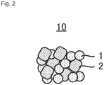
- a cathode mixture 10 shown in Fig. 2 is a cathode mixture used for an all solid-state battery, and a feature thereof is to include a cathode active material 1; and a sulfide solid electrolyte 2, wherein the cathode active material 1 consists of a composite oxide containing Li, Ni, Co, and Mn, the cathode active material 1 has a layered rock-salt crystal phase, and the concentration of cobalt inside the cathode active material 1 is higher than that of a surface of the cathode active material 1.
- the cathode active material 1 consists of a composite oxide containing Li, Ni, Co, and Mn.
- This composite oxide may contain (an) element(s) other than Li, Ni, Co, Mn and O as far as the problem can be solved.
- the composite oxide consists of Li, Ni, Co, Mn, and O.
- the cathode active material 1 has a layered rock-salt crystal phase.
- These diffraction peak positions fluctuate a little according to composition in the cathode active material.
- the values of 2 ⁇ represent the diffraction peak positions in a discharging state (state where Li is not released).
- the cathode active material 1 may include (a) crystal phase(s) other than a layered rock-salt crystal phase as far as the problem can be solved.
- crystal phase(s) other than a layered rock-salt crystal phase Preferably, diffraction peaks only derived from a layered rock-salt crystal phase are confirmed in X-ray diffraction measurement as described above which the cathode active material 1 is subjected to.
- the concentration of cobalt inside the cathode active material 1 is higher than that of the surface of the cathode active material 1.
- the concentration of cobalt may increase either continuously or intermittently from the surface of the cathode active material 1 toward the inside thereof. Increasing the concentration of cobalt inside the cathode active material 1 makes it possible to secure a high capacity as active material. In contrast, lowering the concentration of cobalt of the surface of the cathode active material 1 makes it possible to suppress release of oxygen in charging.
- the composition ratio of Li, Ni, Co, and Mn (and O) in the cathode active material 1 is not specifically limited as long as a layered rock-salt crystal phase is included. As described above, the concentration of cobalt inside the cathode active material 1 is higher than that of its surface. In other words, the surface of the cathode active material 1 has composition different from its inside. Co does not have to exist on the surface of the cathode active material 1. Neither Ni nor Mn has to exist inside the cathode active material 1.
- the inside of the cathode active material 1 preferably has composition represented by LiNi x Co y Mn z O 2 ⁇ (0 ⁇ x ⁇ 0.5, 0 ⁇ y ⁇ 1, 0 ⁇ z ⁇ 0.5, 0.8 ⁇ x + y + z ⁇ 1.2).
- a layered rock-salt type composite oxide is easy to be obtained while the concentration of cobalt is increased.
- the lower limit of x is more preferably no less than 0.25, and the upper limit thereof is more preferably no more than 0.40.
- the lower limit of y is more preferably no less than 0.25, and the upper limit thereof is more preferably no more than 0.40.
- the lower limit of z is more preferably no less than 0.25, and the upper limit thereof is more preferably no more than 0.40. Especially preferably, all of x, y, and z are 1/3.
- the lower limit is more preferably no less than 0.9, and further preferably no less than 0.95, and the upper limit is more preferably no more than 1.1, and further preferably no more than 1.05.
- the molar ratio of O to Li (O/Li) is 2.
- oxygen is excessive, or the layered rock-salt crystal phase is partially deficient in oxygen, compared to the stoichiometric ratio as a layered rock-salt crystal phase, a crystalline structure of the layered rock-salt crystal phase itself is kept, and a desired effect can be exerted.
- the molar ratio of O to Li (O/Li) is preferably 1.6 to 2.2.
- ⁇ is preferably no more than 0.2.
- Specific examples of the composition inside the cathode active material 1 include LiCoO 2 , and LiNi 1/3 Co 1/3 Mn 1/3 O 2 .
- the surface of the cathode active material 1 preferably has composition represented by LiNi ⁇ Co ⁇ Mn ⁇ O 2 ⁇ (0 ⁇ ⁇ ⁇ 0.5, 0 ⁇ ⁇ ⁇ 1, 0 ⁇ ⁇ ⁇ 0.5, 0.8 ⁇ ⁇ + ⁇ + ⁇ ⁇ 1.2, ⁇ ⁇ y).
- the lower limit of ⁇ is more preferably no less than 0.3, and further preferably no less than 0.4.
- the upper limit of ⁇ is more preferably no more than 0.3, and further preferably no more than 0.2.
- ⁇ is smaller than y.
- the lower limit of ⁇ is more preferably no less than 0.3, and further preferably no less than 0.40.
- the lower limit is more preferably no less than 0.9, and further preferably no less than 0.95, and the upper limit is more preferably no more than 1.1, and further preferably no more than 1.05.
- the molar ratio of O to Li (O/Li) is 2.
- a crystalline structure of the layered rock-salt crystal phase itself is kept, and a desired effect can be exerted even if oxygen is excessive, or the layered rock-salt crystal phase is partially deficient in oxygen, compared to the stoichiometric ratio as a layered rock-salt crystal phase.
- the molar ratio of O to Li (O/Li) is preferably 1.6 to 2.2.
- ⁇ is preferably no more than 0.2.
- Specific examples of the composition of the surface of the cathode active material 1 include LiNi 0.4 Co 0.2 Mn 0.4 O 2 , and LiNi 0.5 Mn 0.5 O 2 .
- the rate of increasing a c-axis length of the layered rock-salt crystal phase included inside the cathode active material 1 in charging is higher than that of its surface in charging.
- the rate of increasing a c-axis length of the layered rock-salt crystal phase included inside the cathode active material 1 in charging is preferably no less than 1.012, and that of its surface in charging is preferably lower than 1.012.
- the shape of the cathode active material 1 is not specifically limited, and is preferably in the form of a particle.
- the form may be either a primary particle, or a secondary particle of cohering primary particles.
- too small a particle diameter thereof leads to too large a specific surface area, especially, enlargement of the total area to be coated with a coating layer 3 described later when the coating layer 3 is provided for the surface of the cathode active material 1, and further increase of the volume of the coating layer 3 in the cathode mixture, which is sometimes disadvantageous in view of the process cost, the material cost, and an energy density of a cathode.
- the cathode active material 1 when the cathode active material 1 is in the form of a particle, its mean particle diameter (D 50 ) is preferably 1 ⁇ m to 15 ⁇ m.
- the mean particle diameter (D 50 ) represents a median diameter (50% mean volume particle diameter) derived from particle size distribution measured resulting from a particle counter based on a laser scattering and diffraction method.
- its BET specific surface area is preferably 0.2 m 2 /g to 2.0 m 2 /g.
- the content of the cathode active material 1 in the cathode mixture 10 is not specifically limited, and may be properly determined according to the performance of the battery to be aimed.
- the content of the cathode active material 1 is preferably 30 mass% to 90 mass% if the whole of the cathode mixture 10 (whole of the solid content) is 100 mass%.
- the lower limit is more preferably no less than 50 mass%, and the upper limit is more preferably no more than 85 mass%.
- any sulfide that is used as a solid electrolyte for an all solid-state battery can be employed for the sulfide solid electrolyte 2.
- Examples thereof include Li 2 S-P 2 S 5 , Li 2 S-SiS 2 , LiI-Li 2 S-SiS 2 , LiI-Si 2 S-P 2 S 5 , LiI-LiBr-Li 2 S-P 2 S 5 , LiI-Li 2 S-P 2 S 5 , LiI-Li 2 O-Li 2 S-P 2 S 5 , LiI-Li 2 S-P 2 O 5 , LiI-Li 3 PO 4 -P 2 S 5 , and Li 2 S-P 2 S 5 -GeS 2 .
- a sulfide solid electrolyte containing Li 2 S-P 2 S 5 is more preferable.
- One may be individually used, or two or more may be mixed to be used as the sulfide solid electrolyte 2.
- the shape of the sulfide solid electrolyte 2 is not specifically limited.
- the sulfide solid electrolyte 2 may be in the form of a particle.
- the content of the sulfide solid electrolyte 2 in the cathode mixture 10 is not specifically restricted, and may be properly determined according to the performance of the battery to be aimed.
- the content of the sulfide solid electrolyte 2 is preferably 5 mass% to 65 mass% if the whole of the cathode mixture 10 (whole of the solid content) is 100 mass%.
- the lower limit is more preferably no less than 10 mass%, and the upper limit is more preferably no more than 45 mass%.
- the cathode mixture 10 further includes the coating layer 3 with which the surface of the cathode active material 1 is coated.
- the coating layer 3 is a layer containing Li and Nb, and is especially preferably a layer formed of lithium niobate.
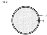
- the coating layer 3 can function as a protective layer for preventing the cathode active material 1 from being directly in contact with the sulfide solid electrolyte 2. From this viewpoint, all over the surface of the cathode active material 1 is preferably coated with the coating layer 3 as shown in Fig. 3 .
- the thickness of the coating layer 3 is not specifically limited, and for example, may be 5 nm to 50 nm.
- the cathode mixture 10 may contain other constituents in addition to the cathode active material 1, the sulfide solid electrolyte 2, and the coating layer 3 as far as the problem can be solved.
- the cathode mixture 10 preferably contains a conductive additive.
- a conductive additive employed for an all solid-state battery can be employed. Examples thereof include carbon materials such as acetylene black (AB), Ketjenblack (KB), vapor grown carbon fiber (VGCF), carbon nanotubes (CNT), carbon nanofibers (CNF), and graphite; and metallic materials such as nickel, aluminum, and stainless steel. Especially, a carbon material is preferable.
- One may be used individually, or two or more may be mixed to be used as the conductive additive. Any shape such as powder and fiber can be employed for the conductive additive.
- the content of the conductive additive in the cathode mixture 10 is not specifically restricted, and may be properly determined according to the performance of the battery to be aimed.
- the content of the conductive additive is preferably 0.5 mass% to 20 mass% if the whole of the cathode mixture 10 is 100 mass%.
- the lower limit is more preferably no less than 1 mass%, and the upper limit is more preferably no more than 10 mass%.
- the cathode mixture 10 preferably contains a binder. Any known one as a binder employed for an all solid-state battery can be employed. For example, at least one selected from styrene-butadiene rubber (SBR), carboxymethyl cellulose (CMC), acrylonitrile-butadiene rubber (ABR), butadiene rubber (BR), polyvinylidene fluoride (PVDF), polytetrafluoroethylene (PTFE), etc. can be used.
- SBR styrene-butadiene rubber
- CMC carboxymethyl cellulose
- ABR acrylonitrile-butadiene rubber
- BR butadiene rubber
- PVDF polyvinylidene fluoride
- PTFE polytetrafluoroethylene
- the content of the binder is preferably 1 mass% to 30 mass% if the whole of the cathode mixture 10 is 100 mass%.
- the lower limit is more preferably no less than 2 mass%, and the upper limit is more preferably no more than 15 mass%.
- the cathode mixture 10 may contain (a) cathode active material(s) other than the cathode active material 1 as far as the problem can be solved. Examples thereof include a spinel type cathode active material, and an olivine type cathode active material.
- the cathode mixture 10 may contain (a) solid electrolyte(s) other than the sulfide solid electrolyte 2 as far as the problem can be solved.
- solid electrolyte(s) other than the sulfide solid electrolyte 2 as far as the problem can be solved.
- oxide solid electrolytes such as lithium lanthanum zirconate, LiPON, Li 1+X Al X Ge 2-X (PO 4 ) 3 , Li-SiO-based glass, and Li-Al-S-O-based glass.
- the concentration of cobalt inside the cathode active material 1 that consists of the composite oxide containing Li, Ni, Co, and Mn, and that has a layered rock-salt crystal phase is increased to secure a high capacity, and at the same time the concentration of cobalt of its surface is lowered, which makes it possible to suppress release of oxygen in charging. That is, when the cathode mixture 10 of this disclosure is used in a cathode 100 of an all solid-state battery 1000 described later, oxidation of the sulfide solid electrolyte due to release of oxygen from the cathode active material can be suppressed, and increase of the internal resistance of the all solid-state battery 1000 can be suppressed.
- the cathode 100 shown in Fig. 4 is a cathode used for an all solid-state battery, and includes the cathode mixture 10, and a cathode current collector 20.
- the cathode mixture 10 is provided for a surface of the cathode current collector 20 in the form of a layer.
- the thickness of a layer consisting of the cathode mixture 10 is preferably 1 ⁇ m to 1 mm.
- the cathode current collector 20 may have conductivity, and for example, may be constituted of metal foil, a metal mesh, etc. Especially, metal foil is preferable.
- metals that may constitute the cathode current collector 20 include Ni, Cr, Au, Pt, Al, Fe, Ti, Zn, and stainless steel.
- the cathode current collector 20 may have some coating layer over its surface.
- the thickness of the cathode current collector 20 is not specifically limited, and for example, is preferably 0.1 ⁇ m to 1 mm, and is more preferably 1 ⁇ m to 100 ⁇ m.
- the all solid-state battery 1000 shown in Fig. 5 includes the cathode 100, an anode 200, and a solid electrolyte layer 300.
- the structure of the cathode 100 is as described above. Detailed description thereof is omitted here.
- the structure of the anode 200 in the all solid-state battery 1000 is obvious for the person skilled in the art. Hereinafter one example thereof will be described.
- the anode 200 usually includes an anode mixture layer 30 containing an anode active material, and containing, as optional constituents, a solid electrolyte, a binder, a conductive additive, and other additives (thickener etc.).
- the anode mixture layer 30 is preferably provided for a surface of an anode current collector 40.
- the anode mixture layer 30 is a layer containing at least an anode active material, and may further contain a solid electrolyte, a binder, a conductive additive, etc. optionally, in addition to the anode active material.
- a known active material may be used as the anode active material.
- known active materials one whose potential at which a predetermined ion is stored/released (charge/discharge potential) is baser than the cathode active material 1 can be used as the anode active material.
- Si or a Si alloy when a lithium ion battery is configured, Si or a Si alloy; a carbon material such as graphite and hard carbon; any oxide such as lithium titanate; a lithium metal or a lithium alloy; or the like can be used as the anode active material.
- the solid electrolyte, the binder, and the conductive additive may be properly selected among the examples for ones used in the cathode mixture 10, to be used.
- the contents of the constituents in the anode mixture layer 30 may be the same as conventional ones.
- the shape of the anode mixture layer 30 may be the same as a conventional one as well. Specifically, the anode mixture layer 30 in the form of a sheet is preferable from the viewpoint that the all solid-state battery 1000 can be easily configured.
- the thickness of the anode mixture layer 30 is preferably 0.1 ⁇ m to 1 mm, and more preferably 1 ⁇ m to 100 ⁇ m.
- the thickness of the anode mixture layer 30 is preferably determined as such that the capacity of the anode 200 is larger than that of the cathode 100.
- the anode current collector 40 may be constituted of metal foil, a metal mesh, etc. Especially, metal foil is preferable. Examples of metals that may constitute the anode current collector 40 include Cu, Ni, Fe, Ti, Co, Zn, and stainless steel. The anode current collector 40 may have some coating layer over its surface. The thickness of the anode current collector 40 is not specifically limited, and for example, is preferably 0.1 ⁇ m to 1 mm, and is more preferably 1 ⁇ m to 100 ⁇ m.
- the anode 200 having the above described structure can be easily produced via a process such as: kneading the anode active material, and the solid electrolyte, binder, and conductive additive which are to be optionally contained, in solvent, to obtain paste or slurry containing an anode mixture, and thereafter applying the paste or slurry to the surface of the anode current collector, to be dried.
- the anode 200 can be produced via not only such a wet process, but also a dry process.
- the constitution of the solid electrolyte layer 300 in the all solid-state battery 1000 is obvious for the person skilled in the art. Hereinafter one example thereof will be described.
- the solid electrolyte layer 300 contains a sold electrolyte, and optionally a binder.
- a sulfide solid electrolyte as described above is preferably employed for the solid electrolyte.
- an inorganic solid electrolyte other than a sulfide solid electrolyte may be contained in addition to a sulfide solid electrolyte as far as a desired effect can be exerted.
- the same one as a binder as described above can be properly selected to be used.
- the contents of the constituents in the solid electrolyte layer 300 may be the same as conventional ones.
- the shape of the solid electrolyte layer 300 may be the same as a conventional one as well. Specifically, the solid electrolyte layer 300 in the form of a sheet is preferable.
- the solid electrolyte layer 300 in the form of a sheet can be easily produced via a process such as: kneading the solid electrolyte, and optionally the binder in solvent, to obtain a slurry electrolyte composition, and thereafter applying this electrolyte composition to a surface of a base material or to (a) surface(s) of the cathode mixture layer and/or anode mixture layer, to be dried; and press-molding the solid electrolyte in a dry process.
- the thickness of the solid electrolyte layer 300 is preferably 0.1 ⁇ m to 300 ⁇ m, and more preferably 0.1 ⁇ m to 100 ⁇ m.
- the all solid-state battery 1000 may include necessary terminals, a battery case, etc. in addition to the cathode 100, the anode 200, and the solid electrolyte layer 300. These members are publicly known, and detailed description thereof is omitted here.
- the cathode mixture 10 can be produced as the flow shown in Fig. 6 . That is, a method S10 for producing the cathode mixture 10 includes: a coating step S1 of coating a surface of an inside active material 1a with an outside active material 1b, to obtain the cathode active material 1; and a mixing step S2 of mixing the cathode active material 1 and the sulfide solid electrolyte 2, to obtain the cathode mixture 10.
- the cathode active material 1 consists of a composite oxide containing Li, Ni, Co, and Mn.
- the cathode active material 1 has a layered rock-salt crystal phase. It is important in the producing method S10 that the concentration of cobalt in the inside active material 1a is higher than that in the outside active material 1b.
- the surface of the inside active material 1a is coated with the outside active material 1b, to obtain the cathode active material 1.
- Both the inside active material 1a and outside active material 1b preferably consist of a composite oxide having a layered rock-salt crystal phase.
- the composite oxide constituting the inside active material 1a preferably consists of a composite oxide having the same composition as the inside of the cathode active material 1. That is, the inside active material 1a preferably has composition represented by LiNi x Co y Mn z O 2 ⁇ (0 ⁇ x ⁇ 0.5, 0 ⁇ y ⁇ 1, 0 ⁇ z ⁇ 0.5, 0.8 ⁇ x + y + z ⁇ 1.2).
- the composite oxide constituting the outside active material 1b preferably consists of a composite oxide having the same composition as the surface of the cathode active material 1.
- the outside active material 1b preferably has composition represented by LiNi ⁇ Co ⁇ Mn ⁇ O 2 ⁇ (0 ⁇ ⁇ ⁇ 0.5, 0 ⁇ ⁇ ⁇ 1, 0 ⁇ ⁇ ⁇ 0.5, 0.8 ⁇ ⁇ + ⁇ + ⁇ ⁇ 1.2, ⁇ ⁇ y).
- Preferred ranges of x, y, z, ⁇ , ⁇ , ⁇ , and ⁇ in the composition formulae are as described above, and detailed description thereof is omitted here.
- the inside active material 1a can be easily obtained by a method known as a method for obtaining a layered rock-salt type lithium composite oxide.
- the inside active material 1a can be easily obtained by, for example, mixing every raw material (a Li compound, a Ni compound, a Co compound, and a Mn compound) so that the materials have the composition ratio as described above, and calcining the mixed materials in a proper atmosphere such as an atmospheric atmosphere at a temperature of no less than a temperature at which a layered rock-salt crystal phase deposits.
- a proper atmosphere such as an atmospheric atmosphere at a temperature of no less than a temperature at which a layered rock-salt crystal phase deposits.
- commercially available one may be used as the inside active material 1a.
- the inside active material 1a is preferably in the form of a particle.
- a method for coating the surface of the inside active material 1 a with the outside active material 1b is not specifically limited.
- the surface of the inside active material 1a can be coated with the outside active material 1b by, for example, coating the surface of the inside active material 1a with raw materials of the outside active material 1b (a Li compound, a Ni compound, a Co compound, and a Mn compound.
- a Li compound, a Ni compound, a Co compound, and a Mn compound a Li compound, a Ni compound, a Co compound, and a Mn compound.
- a proper atmosphere such as an atmospheric atmosphere at a temperature of no less than a temperature at which a layered rock-salt crystal phase deposits, to form the outside active material 1b over the surface of the inside active material 1a.
- solution that dissolves the raw materials of the outside active material 1b is preferably touched to the surface of the inside active material 1a.
- the inside active material 1a is preferably immersed in solution that dissolves the raw materials of the outside active material 1b.
- the thickness of a layer of the outside active material 1b is not specifically limited.
- a layer consisting of the outside active material 1b having a thickness of 10 nm to 200 nm is provided for the surface of the inside active material 1a.
- the thickness of the layer consisting of the outside active material 1b is more preferably 50 nm to 150 nm. No interface is necessary to exist between the inside active material 1a and the outside active material 1b.
- the cathode active material 1 obtained in the coating step S1 does not necessarily have a core-shell structure including the inside active material 1a as a core and the outside active material 1b as a shell, and an intermediate region may be provided between the inside active material 1a and the outside active material 1b.
- the inside active material 1a when the inside active material 1a is immersed in solution that dissolves the raw materials of the outside active material 1b, thereafter to be calcined to coat the surface of the inside active material 1a with the outside active material 1b, there is a case where transition metals diffuse across the interface between the inside active material 1a and the outside active material 1b, to form an intermediate region having composition that is in the middle of the composition of the inside active material 1a and that of the outside active material 1b.
- the rate of increasing a c-axis length of the layered rock-salt crystal phase in charging lowers, and release of oxygen is suppressed.
- the concentration of cobalt is high, capacity as active material can be improved.
- the rate of increasing a c-axis length of the layered rock-salt crystal phase included in the inside active material 1a in charging is higher than that included in the outside active material 1b in charging.
- coating the surface of the cathode active material 1 with the coating layer 3 makes it possible to suppress formation of a high resistance layer on the interface between the cathode active material 1 and the sulfide solid electrolyte 2. That is, in the coating step S1, preferably, the surface of the inside active material 1a is coated with the outside active material 1b to obtain the cathode active material 1, and the surface of the cathode active material 1 is further coated with the coating layer 3 containing Li and Nb (more preferably, a layer formed of lithium niobate).
- a way itself of coating the surface of the cathode active material 1 with the coating layer 3 is publicly known ( JP 2017-059393 A , JP 2015-056307 A , etc.).
- a precursor solution containing niobium and lithium is sprayed and atomized, to be dried and heat-treated, which makes it possible to coat the surface of the cathode active material 1 with the coating layer 3.
- a precursor solution containing niobium and lithium is sprayed and atomized, to be dried and heat-treated, which makes it possible to coat the surface of the cathode active material 1 with the coating layer 3.
- the cathode active material 1 and the sulfide solid electrolyte 2 are mixed to obtain the cathode mixture 10.
- other constituents such as the conductive additive and the binder may be further mixed in addition to the cathode active material 1 and the sulfide solid electrolyte 2.
- a way of mixing the cathode active material 1 and the sulfide solid electrolyte 2 to obtain the cathode mixture 10 is not specifically limited.
- the mixing step S2 can be carried out using a known mixing means. Mixing in the mixing step S2 may be either wet mixing using solvent, or dry mixing not using solvent (mixing of granular materials each other).
- the cathode active material 1 and the sulfide solid electrolyte 2 are mixed together with solvent, to obtain paste or slurry containing the cathode mixture 10.
- a solvent used in this case is not specifically limited.
- the cathode 100 of this disclosure can be produced as follows: that is, a method for producing the cathode 100 includes: a step of producing the cathode mixture 10 by the producing method S10; and a step of layering the cathode mixture 10 onto the surface of the cathode current collector 20.
- the cathode 100 can be easily produced via a process such as applying paste or slurry containing the cathode mixture 10 to the surface of the cathode current collector 20, to be dried.
- the cathode 100 can be produced by not only such a wet process, but also a dry process.
- the all solid-state battery 1000 of this disclosure can be produced as follows: that is, a method for producing the all solid-state battery 1000 includes: a step of producing the cathode 100 by the producing method described above; and a step of layering the cathode 100, the solid electrolyte layer 300, and the anode 200.
- the all solid-state battery 1000 can be produced by, for example, layering the cathode 100, the solid electrolyte layer 300, and the anode 200 as described above, to obtain a laminate, and upon attaching proper terminals etc., sealing up the laminate in a battery case.
- NCM111 means layered rock-salt type LiNi 1/3 Co 1/3 Mn 1/3 O 2
- NCM424" means layered rock-salt type LiNi 0.4 Co 0.2 Mn 0.4 O 2
- NCM505" means layered rock-salt type LiNi 0.5 Mn 0.5 O 2 .
- the deposit generated in the reaction solution was cleaned and dried, to obtain a precursor of an inside active material.
- concentrations of nickel sulfate, cobalt sulfate, and manganese sulfate in the mixed aqueous solution were changed to obtain precursors having various compositions.
- each of the concentrations of nickel sulfate, cobalt sulfate, and manganese sulfate in the mixed aqueous solution was 0.5 mol/L
- each of the concentrations of nickel sulfate and manganese sulfate was 0.6 mol/L, and that of cobalt sulfate was 0.3 mol/L
- each of the concentrations of nickel sulfate and manganese sulfate was 0.7 mol/L, and that of cobalt sulfate was 0 mol/L.
- Powder of the obtained precursor and powder of Li 2 CO 3 were mixed, and heat-treated in an air atmosphere at 700 to 1000°C, to obtain inside active material.
- the numbers of moles of Ni, Co, and Mn contained in the precursor and that of Li included in Li 2 CO 3 were adjusted to have a proper quantity ratio as a layered rock-salt type composite oxide.
- the obtained slurry was moved into a rotary evaporator, and was subjected to evaporation to dryness under a reduced pressure while being stirred as the temperature was kept 50°C, to coat the surface of the inside active material with a precursor of the outside active material.
- the grounded powder was heated at 480°C in an air atmosphere for 3 hours. Thereafter, the resultant was mixed with lithium hydroxide, and calcined at 850°C in an air atmosphere for 2 hours, to coat the surface of the inside active material with the outside active material, to obtain a cathode active material.
- the number of moles of lithium hydroxide was equal to that of the transition metals contained in the precursor of the outside active material.
- the surface of the obtained cathode active material was sputtered with lithium niobate (LiNbO 3 ) by a barrel sputtering method, to be coated.
- the powder of the active material was stirred in a reactor during sputtering so that the surface of the cathode active material was uniformly coated with lithium niobate.
- the cathode active material Li 2 S-P 2 S 5 -based glass ceramic
- a conductive additive VGCF manufactured by Showa Denko K.K.
- anode active material graphite powder
- a sulfide solid electrolyte (same as the above) were put and fully mixed, to be pasty.
- the obtained paste was dripped onto a laboratory dish, to be dried to obtain powder of an anode mixture.
- Powder of NCM111, powder of NCM424, and powder of NCM505 were made conforming to the procedures for making the inside active material, and the ratios of increasing c-axis lengths in charging were measured by the following procedures:
- the made all solid-state battery was subjected to charge/discharge testing under the following conditions:
- the made all solid-state battery was subjected to resistance evaluation testing under the following conditions:
- the made all solid-state battery was subjected to aging testing under the following conditions:
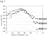
- Table 1 and Fig. 7 show the relations between the amount of extracting Li of layered rock-salt type LiNi x Co 1-2x Mn x O 2 and a c-axis length of a layered rock-salt crystal phase.
- Table 1 Ni [mol%] Co [mol%] Mn [mol%] C-axis length in uncharging [ ⁇ ] C-axis length in charging (max.) [ ⁇ ] Rate of increasing c-axis length [-] NCM111 33 33 33 14.1990 14.4342 1.017 NCM424 40 20 40 14.3060 14.4710 1.012 NCM505 50 0 50 14.4023 14.5082 1.007
- Table 2 shows "compositions of inside active material and outside active material which were used when cathode active material was made", “presence or not of coating layer”, “rate of increasing c-axis length of layered rock-salt crystal phase of inside active material”, and “rate of increasing c-axis length of layered rock-salt crystal phase of outside active material” as to the all solid-state battery according to each of Examples and Comparative Examples.
- Table 2 Composition of inside active material Composition of outside active material Coating layer Rate of increasing c-axis length of inside active material Rate of increasing c-axis length of outside active material
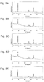
- Figs. 8A to 8E The cathode active materials used in Examples 1 and 2 and Comparative Examples 1 to 3 were subjected to measurement by means of X-ray diffraction before coated with the coating layers. The results are shown in Figs. 8A to 8E.
- Fig. 8A corresponds to Example 1
- Fig. 8B corresponds to Example 2
- Fig. 8C corresponds to Comparative Example 1
- Fig. 8D corresponds to Comparative Example 2
- Fig. 8E corresponds to Comparative Example 3.
- diffraction peaks only derived from a layered rock-salt crystal phase were confirmed, and no different phase was confirmed, as to all the cathode active materials. It is believed that the surfaces of the layered rock-salt type inside active materials were able to be coated with the layered rock-salt type outside active materials in both Examples 1 and 2.
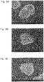
- Figs. 9A to 9C The states of the surfaces of the cathode active materials according to Examples 1 and 2 and Comparative Example 1 were observed by means of SEM. The results are shown in Figs. 9A to 9C. Fig. 9A corresponds to Example 1, Fig. 9B corresponds to Example 2, and Fig. 9C corresponds to Comparative Example 1. As is apparent from the results shown in Figs. 9A to 9C , coating the surface of the inside active material with the outside active material changed the state of the surface of the active material.
- Table 3 shows "capacity measured by charge/discharge testing", “initial resistance value measured by resistance evaluation testing”, “resistance value after aging testing”, and “rate of increasing resistance after aging testing compared with resistance before aging testing” as to the all solid-state battery of each of Examples and Comparative Examples.
- "capacity measured by charge/discharge testing” and “initial resistance value measured by resistance evaluation testing” are relatively represented on the basis of Comparative Example 1 (100).
- Table 3 Capacity (relative value) Initial resistance value (relative value) Increased resistance value Rate of increasing resistance value Ex. 1 99 78 133 171% Ex. 2 100 72 128 178% Comp. Ex. 1 100 100 100 189 189% Comp. Ex. 2 101 138 219 159% Comp. Ex. 3 43 550 660 120%
- Comparative Examples 2 and 3 since the cathode active materials were formed of only composite oxides having low concentrations of cobalt, release of oxygen in charging was suppressed, and the rates of increasing the resistance values were lower than those of Examples 1 and 2 and Comparative Example 1. However, since in Comparative Examples 2 and 3, the initial resistance values were high first of all, there was no advantage over Comparative Example 1. Specifically, in Comparative Example 3, not only the initial resistance value was high, but also the capacity was lowered. The reason why the initial resistances were high in Comparative Examples 2 and 3 is believed to be because lithium ion conductivity in particles lowered accompanying lowering of the concentrations of cobalt.
- Example 3 and Comparative Example 4 were examples where the surfaces of the cathode active materials were not coated with the coating layers (layers of lithium niobate). As is apparent from the comparison between Example 3 and Comparative Example 4, the effect of having lowered the concentration of cobalt of the surface of the cathode active material more than that inside the cathode active material was confirmed as well when the layer of lithium niobate was not included. Since there was no difference between Example 3 and Comparative Example 4 in theoretical capacity, it is believed that difference in capacity in this case was due to difference in initial resistance. That is, the resistance in Example 3 can be said to have been lower.
- the all solid-state battery using the cathode mixture of this disclosure can be used in a wide range of power sources such as a small-sized power source for portable terminals and an onboard large-sized power source.
Landscapes
- Chemical & Material Sciences (AREA)
- Chemical Kinetics & Catalysis (AREA)
- Electrochemistry (AREA)
- General Chemical & Material Sciences (AREA)
- Engineering & Computer Science (AREA)
- Manufacturing & Machinery (AREA)
- Inorganic Chemistry (AREA)
- Composite Materials (AREA)
- Materials Engineering (AREA)
- Physics & Mathematics (AREA)
- Condensed Matter Physics & Semiconductors (AREA)
- General Physics & Mathematics (AREA)
- Battery Electrode And Active Subsutance (AREA)
- Secondary Cells (AREA)
Abstract
Description
- The present application discloses, for example, a cathode mixture used for an all solid-state battery.
-
Patent Literatures 1 to 3 disclose cathode active materials formed of lithium-containing composite oxides. Such a cathode active material formed of a lithium-containing composite oxide can be used in a cathode for an all solid-state battery as well. A composite oxide having a layered rock-salt crystal phase and containing Li, Ni, Co and Mn is a known example of a cathode active material usable for an all solid-state battery. -
- Patent Literature 1:
JP 2014-040363 A - Patent Literature 2:
JP 2015-056307 A - Patent Literature 3:
JP 2017-103065 A - A cathode mixture containing a sulfide solid electrolyte and a cathode active material that is formed of a composite oxide as described above is used in a cathode for an all solid-state battery. Here, according to the new findings of the inventors of the present application, using a cathode mixture containing a sulfide solid electrolyte and a cathode active material that is formed of a composite oxide in an all solid-state battery leads to release of oxygen from the cathode active material when the all solid-state battery is charged, which results in oxidation of the sulfide solid electrolyte. That is, internal resistance in an all solid-state battery using a cathode active material formed of a composite oxide as described above is easy to increase due to oxidation of a sulfide solid electrolyte, which is problematic.
- The present application discloses, as one means for solving the problem, a cathode mixture for an all-solid-state battery, the cathode mixture comprising: a cathode active material; and a sulfide solid electrolyte, wherein the cathode active material consists of a composite oxide containing Li, Ni, Co, and Mn, the cathode active material has a layered rock-salt crystal phase, and a concentration of cobalt inside the cathode active material is higher than a concentration of cobalt of a surface of the cathode active material.
- In the present application, a portion of the cathode active material excluding "a surface of the cathode active material" and "the vicinity of the surface of the cathode active material" may be referred to as "inside the cathode active material".
- "The vicinity of the surface of the cathode active material" may satisfy at least one of the following (1) and (2): (1) as shown in
Fig. 1 , when the cathode active material is observed with a scanning electron microscope, a transmission electron microscope, or the like to obtain a two dimensional image thereof, a region X when a1 / (a1 + a2) is no more than 0.1 is referred to as "the vicinity of the surface of the cathode active material", where an area of the region X that is defined by the surface of the cathode active material and a predetermined depth from the surface is a1, and an area of the whole of the cathode active material is a1 + a2, on the two dimensional image of the cathode active material; and (2) a portion having a depth of 100 nm from the surface of the cathode active material is referred to as "the vicinity of the surface of the cathode active material". - A deeper portion (inside portion) than "the vicinity of the surface of the cathode active material" defined as described above may be referred to as "inside the cathode active material".
- "A concentration of cobalt" means mol% (atm%) of cobalt in all the elements.
- "A concentration of cobalt inside the cathode active material" and "a concentration of cobalt of a surface of the cathode active material" can be easily identified by, for example, measuring the concentrations of the elements inside, and of the surface of the cathode active material by means of SEM-EDX or the like.
- Preferably, the cathode mixture for an all solid-state battery of the present disclosure further comprises: a coating layer with which the surface of the cathode active material is coated, the coating layer containing Li, and Nb.
- The present application discloses, as one means for solving the problem, a cathode for an all solid-state battery, the cathode comprising: the cathode mixture of the present disclosure; and a cathode current collector.
- The present application discloses, as one means for solving the problem, an all solid-state battery comprising: the cathode of the present disclosure; an anode; and a solid electrolyte layer.
- The present application discloses, as one means for solving the problem, a method for producing a cathode mixture for an all solid-state battery, the method comprising: coating a surface of an inside active material with an outside active material, to obtain a cathode active material; and mixing the cathode active material and a sulfide solid electrolyte, to obtain a cathode mixture, wherein the cathode active material consists of a composite oxide containing Li, Ni, Co, and Mn, the cathode active material has a layered rock-salt crystal phase, and a concentration of cobalt in the inside active material is higher than a concentration of cobalt in the outside active material.
- In the method for producing a cathode mixture of the present disclosure, preferably, the inside active material has composition represented by LiNixCoyMnzO2±δ (0 ≤ x ≤ 0.5, 0 < y ≤ 1, 0 ≤ z ≤ 0.5, 0.8 ≤ x + y + z ≤ 1.2), and the outside active material has composition represented by LiNiαCoβMnγO2±δ (0 < α ≤ 0.5, 0 ≤ β ≤ 1, 0 < γ ≤ 0.5, 0.8 ≤ α + β + γ ≤ 1.2, β < y).
- In the method for producing a cathode mixture of the present disclosure, preferably, a rate of increasing a c-axis length of a layered rock-salt crystal phase included in the inside active material in charging is higher than a rate of increasing a c-axis length of a layered rock-salt crystal phase included in the outside active material in charging.
- "A rate of increasing a c-axis length of a layered rock-salt crystal phase included in the inside active material in charging" is obtained as follows: that is, (1) a layered rock-salt type composite oxide having the same composition as the inside active material is used as a cathode active material, to make a half cell (such as a coin cell of an electrolyte solution system); (2) as to this half cell, XRD patterns of the cathode active material (diffraction patterns derived from a layered rock-salt crystal phase) are obtained while the SOC (the amount of extracting Li ions from the cathode active material) is changed. It is noted that XRD patterns in the range of 0 mAh/g to 280 mAh/g in charge capacity are obtained; (3) curve fitting (full pattern matching) is done on the obtained XRD patterns, to obtain a c-axis length of the layered rock-salt crystal phase per amount of extracting Li; and (4) (the maximum value of a c-axis length) / (a c-axis length in uncharging) is calculated to identify "a rate of increasing a c-axis length".
- As to "a rate of increasing a c-axis length of a layered rock-salt crystal phase included in the outside active material in charging", (1) a layered rock-salt type composite oxide having the same composition as the outside active material is used to make a half cell, and "a rate of increasing a c-axis length" is identified via the same operations as (2) to (4) described above.
- In the method for producing a cathode mixture of the present disclosure, preferably, in said coating, the surface of the inside active material is coated with the outside active material, to obtain the cathode active material, and a surface of the cathode active material is further coated with a coating layer containing Li, and Nb.
- The present application discloses, as one means for solving the problem, a method for producing a cathode for an all solid-state battery, the method comprising: producing a cathode mixture by the method of the present disclosure; and layering the cathode mixture onto a surface of a cathode current collector.
- The present application discloses, as one means for solving the problem, a method for producing an all solid-state battery, the method comprising: producing a cathode by the method of the present disclosure; and layering the cathode, a solid electrolyte layer, and an anode.
- According to the new findings of the inventors of the present application, a crystalline structure of a cathode active material consisting of a layered rock-salt type composite oxide containing Li, Ni, Co and Mn becomes unstable when a battery is charged (especially at a high voltage), which makes it easy for the cathode active material to release oxygen. It is believed that the amount of Li ions extracted from the layered rock-salt crystalline structure increases at a high potential, to increase repulsion between oxygen-oxygen that compose the crystalline structure, which is a direct driving force for change in the crystalline structure. In contrast, the amount of extracting Li ions from a cathode active material at a predetermined potential is determined according to the amount of ions (especially cobalt) whose valences have been changed until the predetermined potential is reached. From the above, it seems to be effective to lower the concentration of cobalt in a layered rock-salt type composite oxide for suppressing release of oxygen in charging. However, if the concentration of cobalt in a layered rock-salt type composite oxide is lowered, the capacity as a cathode active material may decrease, and ion conductivity may lower. On the other hand, since oxygen is believed to be released from a cathode active material conspicuously around the interface between the cathode active material and a sulfide solid electrolyte, it is expected that lowering the concentration of cobalt of the surface of a cathode active material makes it possible to effectively suppress release of oxygen in charging as keeping a desired capacity etc.
- In the cathode mixture of this disclosure, while the concentration of cobalt inside a layered rock-salt type cathode active material is increased to secure a high capacity, the concentration of cobalt of its surface is lowered, to achieve stabilization of a crystalline structure on the surface, which makes it possible to suppress release of oxygen in charging. That is, if the cathode mixture of this disclosure is used in a cathode of an all solid-state battery, oxidization of a sulfide solid electrolyte accompanying release of oxygen from a cathode active material can be suppressed, and increase of the internal resistance of the all solid-state battery can be suppressed.
-
-
Fig. 1 is an explanatory schematic view of "the vicinity of the surface of the cathode active material" and "inside the cathode active material"; -
Fig. 2 is an explanatory schematic view of acathode mixture 10; -
Fig. 3 is an explanatory schematic view of acoating layer 3; -
Fig. 4 is an explanatory schematic view of acathode 100; -
Fig. 5 is an explanatory schematic view of an all solid-state battery 1000; -
Fig. 6 is an explanatory flowchart of a method for producing thecathode mixture 10; -
Fig. 7 shows relations between the amount of extracting Li and a c-axis length of a layered rock-salt crystal phase as to a layered rock-salt type composite oxide containing Li, Ni, Co, and Mn: NCM111 corresponds to layered rock-salt type LiNi1/3Co1/3Mn1/3O2, NCM424 corresponds to layered rock-salt type LiNi0.4Co0.2Mn0.4O2, and NCM505 corresponds to layered rock-salt type LiNi0.5Mn0.5O2; -
Figs. 8A to 8E show X-ray diffraction patterns of cathode active materials:Fig. 8A corresponds to Example 1,Fig. 8B corresponds to Example 2,Fig. 8C corresponds to Comparative Example 1,Fig. 8D corresponds to Comparative Example 2, andFig. 8E corresponds to Comparative Example 3; and -
Figs. 9A to 9C show SEM images of the cathode active materials:Fig. 9A corresponds to Example 1,Fig. 9B corresponds to Example 2, andFig. 9C corresponds to Comparative Example 1. - A
cathode mixture 10 shown inFig. 2 is a cathode mixture used for an all solid-state battery, and a feature thereof is to include a cathodeactive material 1; and a sulfidesolid electrolyte 2, wherein the cathodeactive material 1 consists of a composite oxide containing Li, Ni, Co, and Mn, the cathodeactive material 1 has a layered rock-salt crystal phase, and the concentration of cobalt inside the cathodeactive material 1 is higher than that of a surface of the cathodeactive material 1. - The cathode
active material 1 consists of a composite oxide containing Li, Ni, Co, and Mn. This composite oxide may contain (an) element(s) other than Li, Ni, Co, Mn and O as far as the problem can be solved. Preferably, the composite oxide consists of Li, Ni, Co, Mn, and O. The cathodeactive material 1 has a layered rock-salt crystal phase. For example, diffraction peaks derived from a layered rock-salt crystal phase are preferably confirmed at positions where 2θ = 18.5±0.5° (plane 003), 37.0±0.5° (plane 101), 38±1° (plane 006 and plane 102), 45±1° (plane 104), 49±1° (plane 105) and 59±1° (plane 107) in X-ray diffraction measurement using CuKα as a source which the cathodeactive material 1 is subjected to. These diffraction peak positions fluctuate a little according to composition in the cathode active material. The values of 2θ represent the diffraction peak positions in a discharging state (state where Li is not released). The cathodeactive material 1 may include (a) crystal phase(s) other than a layered rock-salt crystal phase as far as the problem can be solved. Preferably, diffraction peaks only derived from a layered rock-salt crystal phase are confirmed in X-ray diffraction measurement as described above which the cathodeactive material 1 is subjected to. - It is important that in the
cathode mixture 10 of this disclosure, the concentration of cobalt inside the cathodeactive material 1 is higher than that of the surface of the cathodeactive material 1. The concentration of cobalt may increase either continuously or intermittently from the surface of the cathodeactive material 1 toward the inside thereof. Increasing the concentration of cobalt inside the cathodeactive material 1 makes it possible to secure a high capacity as active material. In contrast, lowering the concentration of cobalt of the surface of the cathodeactive material 1 makes it possible to suppress release of oxygen in charging. - The composition ratio of Li, Ni, Co, and Mn (and O) in the cathode
active material 1 is not specifically limited as long as a layered rock-salt crystal phase is included. As described above, the concentration of cobalt inside the cathodeactive material 1 is higher than that of its surface. In other words, the surface of the cathodeactive material 1 has composition different from its inside. Co does not have to exist on the surface of the cathodeactive material 1. Neither Ni nor Mn has to exist inside the cathodeactive material 1. - For example, the inside of the cathode
active material 1 preferably has composition represented by LiNixCoyMnzO2±δ (0 ≤ x ≤ 0.5, 0 < y ≤ 1, 0 ≤ z ≤ 0.5, 0.8 ≤ x + y + z ≤ 1.2). When the inside of the cathodeactive material 1 has such composition, a layered rock-salt type composite oxide is easy to be obtained while the concentration of cobalt is increased. The lower limit of x is more preferably no less than 0.25, and the upper limit thereof is more preferably no more than 0.40. The lower limit of y is more preferably no less than 0.25, and the upper limit thereof is more preferably no more than 0.40. The lower limit of z is more preferably no less than 0.25, and the upper limit thereof is more preferably no more than 0.40. Especially preferably, all of x, y, and z are 1/3. The molar ratio of the transition metals (total of Ni, Co, and Mn) to Li is preferably 1 (that is, x + y + z = 1). However, even if Li is a little excessive or a little short compared to the transition metals, a layered rock-salt crystal phase can be obtained, and a desired effect can be exerted. In this point, as represented by the composition formula, the molar ratio of the transition metals to Li is preferably 0.8 to 1.2 (0.8 ≤ x + y + z ≤ 1.2). The lower limit is more preferably no less than 0.9, and further preferably no less than 0.95, and the upper limit is more preferably no more than 1.1, and further preferably no more than 1.05. In the stoichiometric ratio as a layered rock-salt crystal phase, the molar ratio of O to Li (O/Li) is 2. However, even if oxygen is excessive, or the layered rock-salt crystal phase is partially deficient in oxygen, compared to the stoichiometric ratio as a layered rock-salt crystal phase, a crystalline structure of the layered rock-salt crystal phase itself is kept, and a desired effect can be exerted. In this point, for example, the molar ratio of O to Li (O/Li) is preferably 1.6 to 2.2. Or, in the composition formula, δ is preferably no more than 0.2. Specific examples of the composition inside the cathodeactive material 1 include LiCoO2, and LiNi1/3Co1/3Mn1/3O2. - For example, the surface of the cathode
active material 1 preferably has composition represented by LiNiαCoβMnγO2±δ (0 < α ≤ 0.5, 0 ≤ β ≤ 1, 0 < γ ≤ 0.5, 0.8 ≤ α + β + γ ≤ 1.2, β < y). When the surface of the cathodeactive material 1 has such composition, a layered rock-salt type composite oxide is easy to be obtained while the concentration of cobalt is lowered. The lower limit of α is more preferably no less than 0.3, and further preferably no less than 0.4. The upper limit of β is more preferably no more than 0.3, and further preferably no more than 0.2. It is noted that β is smaller than y. The lower limit of γ is more preferably no less than 0.3, and further preferably no less than 0.40. The molar ratio of the transition metals (total of Ni, Co, and Mn) to Li is preferably 1 (that is, α + β + γ = 1). However, even if Li is a little excessive or a little short compared to the transition metals, a layered rock-salt crystal phase can be obtained, and a desired effect can be exerted. In this point, as represented by the composition formula, the molar ratio of the transition metals to Li is preferably 0.8 to 1.2 (0.8 ≤ α + β + γ ≤ 1.2). The lower limit is more preferably no less than 0.9, and further preferably no less than 0.95, and the upper limit is more preferably no more than 1.1, and further preferably no more than 1.05. In the stoichiometric ratio as a layered rock-salt crystal phase, the molar ratio of O to Li (O/Li) is 2. However, a crystalline structure of the layered rock-salt crystal phase itself is kept, and a desired effect can be exerted even if oxygen is excessive, or the layered rock-salt crystal phase is partially deficient in oxygen, compared to the stoichiometric ratio as a layered rock-salt crystal phase. In this point, for example, the molar ratio of O to Li (O/Li) is preferably 1.6 to 2.2. Or, in the composition formula, δ is preferably no more than 0.2. Specific examples of the composition of the surface of the cathodeactive material 1 include LiNi0.4Co0.2Mn0.4O2, and LiNi0.5Mn0.5O2. - According to the findings of the inventors of the present application, in a layered rock-salt type cathode active material as described above, as the concentration of cobalt that is a component of a layered rock-salt crystal phase is low, the rate of increasing a c-axis length of the layered rock-salt crystal phase in charging lowers. This seems to be because repulsion between oxygen-oxygen is small. Therefore, it is believed that as the concentration of cobalt is lower, release of oxygen in charging is suppressed more. On the other hand, as described above, when the concentration of cobalt is low in a layered rock-salt type cathode active material, the capacity as active material may be low, and lithium ion conductivity may lower. In view of these circumstances, in order to suppress release of oxygen in charging as keeping a high capacity, it is effective to make the concentration of cobalt inside the cathode
active material 1 higher than that of its surface as described above. In other words, preferably, the rate of increasing a c-axis length of the layered rock-salt crystal phase included inside the cathodeactive material 1 in charging is higher than that of its surface in charging. Specifically, the rate of increasing a c-axis length of the layered rock-salt crystal phase included inside the cathodeactive material 1 in charging is preferably no less than 1.012, and that of its surface in charging is preferably lower than 1.012. - The shape of the cathode
active material 1 is not specifically limited, and is preferably in the form of a particle. In this case, the form may be either a primary particle, or a secondary particle of cohering primary particles. When the cathodeactive material 1 is in the form of a particle, too small a particle diameter thereof leads to too large a specific surface area, especially, enlargement of the total area to be coated with acoating layer 3 described later when thecoating layer 3 is provided for the surface of the cathodeactive material 1, and further increase of the volume of thecoating layer 3 in the cathode mixture, which is sometimes disadvantageous in view of the process cost, the material cost, and an energy density of a cathode. In contrast, too large a particle diameter thereof leads to slow ion diffusion in the particle, which easily makes the initial internal resistance high when the cathodeactive material 1 is used in an all solid-state battery. In view of this, when the cathodeactive material 1 is in the form of a particle, its mean particle diameter (D50) is preferably 1 µm to 15 µm. The mean particle diameter (D50) represents a median diameter (50% mean volume particle diameter) derived from particle size distribution measured resulting from a particle counter based on a laser scattering and diffraction method. When the cathodeactive material 1 is in the form of a particle, its BET specific surface area is preferably 0.2 m2/g to 2.0 m2/g. - The content of the cathode
active material 1 in thecathode mixture 10 is not specifically limited, and may be properly determined according to the performance of the battery to be aimed. For example, the content of the cathodeactive material 1 is preferably 30 mass% to 90 mass% if the whole of the cathode mixture 10 (whole of the solid content) is 100 mass%. The lower limit is more preferably no less than 50 mass%, and the upper limit is more preferably no more than 85 mass%. - Any sulfide that is used as a solid electrolyte for an all solid-state battery can be employed for the sulfide
solid electrolyte 2. Examples thereof include Li2S-P2S5, Li2S-SiS2, LiI-Li2S-SiS2, LiI-Si2S-P2S5, LiI-LiBr-Li2S-P2S5, LiI-Li2S-P2S5, LiI-Li2O-Li2S-P2S5, LiI-Li2S-P2O5, LiI-Li3PO4-P2S5, and Li2S-P2S5-GeS2. Among them, specifically, a sulfide solid electrolyte containing Li2S-P2S5 is more preferable. One may be individually used, or two or more may be mixed to be used as the sulfidesolid electrolyte 2. The shape of the sulfidesolid electrolyte 2 is not specifically limited. For example, the sulfidesolid electrolyte 2 may be in the form of a particle. - The content of the sulfide
solid electrolyte 2 in thecathode mixture 10 is not specifically restricted, and may be properly determined according to the performance of the battery to be aimed. For example, the content of the sulfidesolid electrolyte 2 is preferably 5 mass% to 65 mass% if the whole of the cathode mixture 10 (whole of the solid content) is 100 mass%. The lower limit is more preferably no less than 10 mass%, and the upper limit is more preferably no more than 45 mass%. - Preferably, the
cathode mixture 10 further includes thecoating layer 3 with which the surface of the cathodeactive material 1 is coated. Thecoating layer 3 is a layer containing Li and Nb, and is especially preferably a layer formed of lithium niobate. When the cathodeactive material 1 is directly in contact with the sulfidesolid electrolyte 2 in thecathode mixture 10, there is a case where the cathodeactive material 1 reacts with the sulfidesolid electrolyte 2, to form a high resistance layer. In this point, thecoating layer 3 can function as a protective layer for preventing the cathodeactive material 1 from being directly in contact with the sulfidesolid electrolyte 2. From this viewpoint, all over the surface of the cathodeactive material 1 is preferably coated with thecoating layer 3 as shown inFig. 3 . The thickness of thecoating layer 3 is not specifically limited, and for example, may be 5 nm to 50 nm. - The
cathode mixture 10 may contain other constituents in addition to the cathodeactive material 1, the sulfidesolid electrolyte 2, and thecoating layer 3 as far as the problem can be solved. - The
cathode mixture 10 preferably contains a conductive additive. Any known one as a conductive additive employed for an all solid-state battery can be employed. Examples thereof include carbon materials such as acetylene black (AB), Ketjenblack (KB), vapor grown carbon fiber (VGCF), carbon nanotubes (CNT), carbon nanofibers (CNF), and graphite; and metallic materials such as nickel, aluminum, and stainless steel. Especially, a carbon material is preferable. One may be used individually, or two or more may be mixed to be used as the conductive additive. Any shape such as powder and fiber can be employed for the conductive additive. The content of the conductive additive in thecathode mixture 10 is not specifically restricted, and may be properly determined according to the performance of the battery to be aimed. For example, the content of the conductive additive is preferably 0.5 mass% to 20 mass% if the whole of thecathode mixture 10 is 100 mass%. The lower limit is more preferably no less than 1 mass%, and the upper limit is more preferably no more than 10 mass%. - The
cathode mixture 10 preferably contains a binder. Any known one as a binder employed for an all solid-state battery can be employed. For example, at least one selected from styrene-butadiene rubber (SBR), carboxymethyl cellulose (CMC), acrylonitrile-butadiene rubber (ABR), butadiene rubber (BR), polyvinylidene fluoride (PVDF), polytetrafluoroethylene (PTFE), etc. can be used. The content of the binder in thecathode mixture 10 is not specifically limited, and may be properly determined according to the performance of the battery to be aimed. For example, the content of the binder is preferably 1 mass% to 30 mass% if the whole of thecathode mixture 10 is 100 mass%. The lower limit is more preferably no less than 2 mass%, and the upper limit is more preferably no more than 15 mass%. - The
cathode mixture 10 may contain (a) cathode active material(s) other than the cathodeactive material 1 as far as the problem can be solved. Examples thereof include a spinel type cathode active material, and an olivine type cathode active material. - The
cathode mixture 10 may contain (a) solid electrolyte(s) other than the sulfidesolid electrolyte 2 as far as the problem can be solved. Examples thereof include oxide solid electrolytes such as lithium lanthanum zirconate, LiPON, Li1+XAlXGe2-X(PO4)3, Li-SiO-based glass, and Li-Al-S-O-based glass. - As described above, in the
cathode mixture 10 of this disclosure, the concentration of cobalt inside the cathodeactive material 1 that consists of the composite oxide containing Li, Ni, Co, and Mn, and that has a layered rock-salt crystal phase is increased to secure a high capacity, and at the same time the concentration of cobalt of its surface is lowered, which makes it possible to suppress release of oxygen in charging. That is, when thecathode mixture 10 of this disclosure is used in acathode 100 of an all solid-state battery 1000 described later, oxidation of the sulfide solid electrolyte due to release of oxygen from the cathode active material can be suppressed, and increase of the internal resistance of the all solid-state battery 1000 can be suppressed. - The
cathode 100 shown inFig. 4 is a cathode used for an all solid-state battery, and includes thecathode mixture 10, and a cathodecurrent collector 20. - Materials constituting the
cathode mixture 10 are as described above. In thecathode 100 shown inFig. 4 , thecathode mixture 10 is provided for a surface of the cathodecurrent collector 20 in the form of a layer. In this case, for example, the thickness of a layer consisting of thecathode mixture 10 is preferably 1 µm to 1 mm. - The cathode
current collector 20 may have conductivity, and for example, may be constituted of metal foil, a metal mesh, etc. Especially, metal foil is preferable. Examples of metals that may constitute the cathodecurrent collector 20 include Ni, Cr, Au, Pt, Al, Fe, Ti, Zn, and stainless steel. The cathodecurrent collector 20 may have some coating layer over its surface. The thickness of the cathodecurrent collector 20 is not specifically limited, and for example, is preferably 0.1 µm to 1 mm, and is more preferably 1 µm to 100 µm. - The all solid-
state battery 1000 shown inFig. 5 includes thecathode 100, ananode 200, and asolid electrolyte layer 300. - The structure of the
cathode 100 is as described above. Detailed description thereof is omitted here. - The structure of the
anode 200 in the all solid-state battery 1000 is obvious for the person skilled in the art. Hereinafter one example thereof will be described. Theanode 200 usually includes ananode mixture layer 30 containing an anode active material, and containing, as optional constituents, a solid electrolyte, a binder, a conductive additive, and other additives (thickener etc.). Theanode mixture layer 30 is preferably provided for a surface of an anodecurrent collector 40. - The
anode mixture layer 30 is a layer containing at least an anode active material, and may further contain a solid electrolyte, a binder, a conductive additive, etc. optionally, in addition to the anode active material. A known active material may be used as the anode active material. Among known active materials, one whose potential at which a predetermined ion is stored/released (charge/discharge potential) is baser than the cathodeactive material 1 can be used as the anode active material. For example, when a lithium ion battery is configured, Si or a Si alloy; a carbon material such as graphite and hard carbon; any oxide such as lithium titanate; a lithium metal or a lithium alloy; or the like can be used as the anode active material. The solid electrolyte, the binder, and the conductive additive may be properly selected among the examples for ones used in thecathode mixture 10, to be used. The contents of the constituents in theanode mixture layer 30 may be the same as conventional ones. The shape of theanode mixture layer 30 may be the same as a conventional one as well. Specifically, theanode mixture layer 30 in the form of a sheet is preferable from the viewpoint that the all solid-state battery 1000 can be easily configured. In this case, for example, the thickness of theanode mixture layer 30 is preferably 0.1 µm to 1 mm, and more preferably 1 µm to 100 µm. The thickness of theanode mixture layer 30 is preferably determined as such that the capacity of theanode 200 is larger than that of thecathode 100. - The anode
current collector 40 may be constituted of metal foil, a metal mesh, etc. Especially, metal foil is preferable. Examples of metals that may constitute the anodecurrent collector 40 include Cu, Ni, Fe, Ti, Co, Zn, and stainless steel. The anodecurrent collector 40 may have some coating layer over its surface. The thickness of the anodecurrent collector 40 is not specifically limited, and for example, is preferably 0.1 µm to 1 mm, and is more preferably 1 µm to 100 µm. - The
anode 200 having the above described structure can be easily produced via a process such as: kneading the anode active material, and the solid electrolyte, binder, and conductive additive which are to be optionally contained, in solvent, to obtain paste or slurry containing an anode mixture, and thereafter applying the paste or slurry to the surface of the anode current collector, to be dried. Theanode 200 can be produced via not only such a wet process, but also a dry process. - The constitution of the
solid electrolyte layer 300 in the all solid-state battery 1000 is obvious for the person skilled in the art. Hereinafter one example thereof will be described. Thesolid electrolyte layer 300 contains a sold electrolyte, and optionally a binder. For example, a sulfide solid electrolyte as described above is preferably employed for the solid electrolyte. For example, an inorganic solid electrolyte other than a sulfide solid electrolyte may be contained in addition to a sulfide solid electrolyte as far as a desired effect can be exerted. The same one as a binder as described above can be properly selected to be used. The contents of the constituents in thesolid electrolyte layer 300 may be the same as conventional ones. The shape of thesolid electrolyte layer 300 may be the same as a conventional one as well. Specifically, thesolid electrolyte layer 300 in the form of a sheet is preferable. For example, thesolid electrolyte layer 300 in the form of a sheet can be easily produced via a process such as: kneading the solid electrolyte, and optionally the binder in solvent, to obtain a slurry electrolyte composition, and thereafter applying this electrolyte composition to a surface of a base material or to (a) surface(s) of the cathode mixture layer and/or anode mixture layer, to be dried; and press-molding the solid electrolyte in a dry process. In this case, for example, the thickness of thesolid electrolyte layer 300 is preferably 0.1 µm to 300 µm, and more preferably 0.1 µm to 100 µm. - Needless to say, the all solid-
state battery 1000 may include necessary terminals, a battery case, etc. in addition to thecathode 100, theanode 200, and thesolid electrolyte layer 300. These members are publicly known, and detailed description thereof is omitted here. - For example, the
cathode mixture 10 can be produced as the flow shown inFig. 6 . That is, a method S10 for producing thecathode mixture 10 includes: a coating step S1 of coating a surface of an inside active material 1a with an outside active material 1b, to obtain the cathodeactive material 1; and a mixing step S2 of mixing the cathodeactive material 1 and the sulfidesolid electrolyte 2, to obtain thecathode mixture 10. Here, the cathodeactive material 1 consists of a composite oxide containing Li, Ni, Co, and Mn. The cathodeactive material 1 has a layered rock-salt crystal phase. It is important in the producing method S10 that the concentration of cobalt in the inside active material 1a is higher than that in the outside active material 1b. - In the coating step S1, the surface of the inside active material 1a is coated with the outside active material 1b, to obtain the cathode
active material 1. Both the inside active material 1a and outside active material 1b preferably consist of a composite oxide having a layered rock-salt crystal phase. - The composite oxide constituting the inside active material 1a preferably consists of a composite oxide having the same composition as the inside of the cathode
active material 1. That is, the inside active material 1a preferably has composition represented by LiNixCoyMnzO2±δ (0 ≤ x ≤ 0.5, 0 < y ≤ 1, 0 ≤ z ≤ 0.5, 0.8 ≤ x + y + z ≤ 1.2). The composite oxide constituting the outside active material 1b preferably consists of a composite oxide having the same composition as the surface of the cathodeactive material 1. That is, the outside active material 1b preferably has composition represented by LiNiαCoβMnγO2±δ (0 < α < 0.5, 0 ≤ β ≤ 1, 0 < γ ≤ 0.5, 0.8 ≤ α + β + γ ≤ 1.2, β < y). Preferred ranges of x, y, z, α, β, γ, and δ in the composition formulae are as described above, and detailed description thereof is omitted here. - The inside active material 1a can be easily obtained by a method known as a method for obtaining a layered rock-salt type lithium composite oxide. The inside active material 1a can be easily obtained by, for example, mixing every raw material (a Li compound, a Ni compound, a Co compound, and a Mn compound) so that the materials have the composition ratio as described above, and calcining the mixed materials in a proper atmosphere such as an atmospheric atmosphere at a temperature of no less than a temperature at which a layered rock-salt crystal phase deposits. Alternatively, commercially available one may be used as the inside active material 1a. The inside active material 1a is preferably in the form of a particle.
- A method for coating the surface of the inside active material 1 a with the outside active material 1b is not specifically limited. For example, the surface of the inside active material 1a can be coated with the outside active material 1b by, for example, coating the surface of the inside active material 1a with raw materials of the outside active material 1b (a Li compound, a Ni compound, a Co compound, and a Mn compound. Preferably acetate, a nitrate, or a sulfate; a hydroxide; or the like), and calcining the resultant in a proper atmosphere such as an atmospheric atmosphere at a temperature of no less than a temperature at which a layered rock-salt crystal phase deposits, to form the outside active material 1b over the surface of the inside active material 1a. When the surface of the inside active material 1a is coated with raw materials of the outside active material 1b, solution that dissolves the raw materials of the outside active material 1b is preferably touched to the surface of the inside active material 1a. Specifically, the inside active material 1a is preferably immersed in solution that dissolves the raw materials of the outside active material 1b. In this case, preferably one may perform calcining as described above after solvent is removed by means of a rotary evaporator or the like.
- When the surface of the inside active material 1a is coated with the outside active material 1b, the thickness of a layer of the outside active material 1b is not specifically limited. Preferably, a layer consisting of the outside active material 1b having a thickness of 10 nm to 200 nm is provided for the surface of the inside active material 1a. The thickness of the layer consisting of the outside active material 1b is more preferably 50 nm to 150 nm. No interface is necessary to exist between the inside active material 1a and the outside active material 1b. That is, the cathode
active material 1 obtained in the coating step S1 does not necessarily have a core-shell structure including the inside active material 1a as a core and the outside active material 1b as a shell, and an intermediate region may be provided between the inside active material 1a and the outside active material 1b. According to the findings of the inventors of the present disclosure, when the inside active material 1a is immersed in solution that dissolves the raw materials of the outside active material 1b, thereafter to be calcined to coat the surface of the inside active material 1a with the outside active material 1b, there is a case where transition metals diffuse across the interface between the inside active material 1a and the outside active material 1b, to form an intermediate region having composition that is in the middle of the composition of the inside active material 1a and that of the outside active material 1b. - As described above, in a layered rock-salt type cathode active material, as the concentration of cobalt that is a component of a layered rock-salt crystal phase is low, the rate of increasing a c-axis length of the layered rock-salt crystal phase in charging lowers, and release of oxygen is suppressed. In contrast, as the concentration of cobalt is high, capacity as active material can be improved. In order to achieve both suppression of release of oxygen, and a high capacity, it is effective to make the concentration of cobalt inside the cathode
active material 1 higher than that of its surface as described above. In view of this, in the producing method S10, preferably, the rate of increasing a c-axis length of the layered rock-salt crystal phase included in the inside active material 1a in charging is higher than that included in the outside active material 1b in charging. - As described above, coating the surface of the cathode
active material 1 with thecoating layer 3 makes it possible to suppress formation of a high resistance layer on the interface between the cathodeactive material 1 and the sulfidesolid electrolyte 2. That is, in the coating step S1, preferably, the surface of the inside active material 1a is coated with the outside active material 1b to obtain the cathodeactive material 1, and the surface of the cathodeactive material 1 is further coated with thecoating layer 3 containing Li and Nb (more preferably, a layer formed of lithium niobate). A way itself of coating the surface of the cathodeactive material 1 with thecoating layer 3 is publicly known (JP 2017-059393 A JP 2015-056307 A active material 1 with thecoating layer 3. Or, one may deposit thecoating layer 3 on the surface of the cathodeactive material 1 by sputtering or the like. - In the mixing step S2, the cathode
active material 1 and the sulfidesolid electrolyte 2 are mixed to obtain thecathode mixture 10. As described above, other constituents such as the conductive additive and the binder may be further mixed in addition to the cathodeactive material 1 and the sulfidesolid electrolyte 2. A way of mixing the cathodeactive material 1 and the sulfidesolid electrolyte 2 to obtain thecathode mixture 10 is not specifically limited. The mixing step S2 can be carried out using a known mixing means. Mixing in the mixing step S2 may be either wet mixing using solvent, or dry mixing not using solvent (mixing of granular materials each other). From the viewpoint that materials can be mixed more uniformly, wet mixing using solvent is preferable. Specifically, the cathodeactive material 1 and the sulfidesolid electrolyte 2 are mixed together with solvent, to obtain paste or slurry containing thecathode mixture 10. A solvent used in this case is not specifically limited. - For example, the
cathode 100 of this disclosure can be produced as follows: that is, a method for producing thecathode 100 includes: a step of producing thecathode mixture 10 by the producing method S10; and a step of layering thecathode mixture 10 onto the surface of the cathodecurrent collector 20. Specifically, thecathode 100 can be easily produced via a process such as applying paste or slurry containing thecathode mixture 10 to the surface of the cathodecurrent collector 20, to be dried. Thecathode 100 can be produced by not only such a wet process, but also a dry process. - For example, the all solid-
state battery 1000 of this disclosure can be produced as follows: that is, a method for producing the all solid-state battery 1000 includes: a step of producing thecathode 100 by the producing method described above; and a step of layering thecathode 100, thesolid electrolyte layer 300, and theanode 200. The all solid-state battery 1000 can be produced by, for example, layering thecathode 100, thesolid electrolyte layer 300, and theanode 200 as described above, to obtain a laminate, and upon attaching proper terminals etc., sealing up the laminate in a battery case. - In the following Examples, "NCM111" means layered rock-salt type LiNi1/3Co1/3Mn1/3O2, "NCM424" means layered rock-salt type LiNi0.4Co0.2Mn0.4O2, and "NCM505" means layered rock-salt type LiNi0.5Mn0.5O2.
- In a reactor, pure water was put, and nitrogen bubbling was performed to obtain an inert atmosphere. Into this reactor, 500 mL of a mixed aqueous solution of nickel sulfate, cobalt sulfate, and manganese sulfate was slowly dropped. At the same time, a 28% ammonia solution and a 10 mol/L sodium hydroxide solution were dropped together, to keep pH in the reactor a proper value (basicity). In the reactor, stirring was continued to be performed strongly so that pH was even all over. At this time, since transition-metal ions contained in the dropped mixed aqueous solution immediately deposited as a hydroxide, the solution in the reactor gradually became cloudy. The deposit generated in the reaction solution was cleaned and dried, to obtain a precursor of an inside active material. The concentrations of nickel sulfate, cobalt sulfate, and manganese sulfate in the mixed aqueous solution were changed to obtain precursors having various compositions. Specifically, when NCM111 was made, each of the concentrations of nickel sulfate, cobalt sulfate, and manganese sulfate in the mixed aqueous solution was 0.5 mol/L; when NCM424 was made, each of the concentrations of nickel sulfate and manganese sulfate was 0.6 mol/L, and that of cobalt sulfate was 0.3 mol/L; and when NCM505 was made, each of the concentrations of nickel sulfate and manganese sulfate was 0.7 mol/L, and that of cobalt sulfate was 0 mol/L.
- Powder of the obtained precursor and powder of Li2CO3 were mixed, and heat-treated in an air atmosphere at 700 to 1000°C, to obtain inside active material. The numbers of moles of Ni, Co, and Mn contained in the precursor and that of Li included in Li2CO3 were adjusted to have a proper quantity ratio as a layered rock-salt type composite oxide.
- Into a vessel, 700mL of ethanol at an ambient temperature was put, and nickel acetate, cobalt acetate, and manganese acetate were added thereto while ethanol was stirred, to be dissolved, so that when an outside active material was to be NCM505, 0.026 mol of Ni and 0.026 mol of Mn were contained in the solution, and when the outside active material was to be NCM424, 0.021 mol of Ni, 0.021 mol of Mn, and 0.010 mol of Co were contained in the solution. Further, 0.32 mol (the number of moles on the basis of the transition metals) of powder of the inside active material was added thereto, to be stirred again to obtain slurry. The obtained slurry was moved into a rotary evaporator, and was subjected to evaporation to dryness under a reduced pressure while being stirred as the temperature was kept 50°C, to coat the surface of the inside active material with a precursor of the outside active material.
- After powder obtained above was ground by means of a mortar, the grounded powder was heated at 480°C in an air atmosphere for 3 hours. Thereafter, the resultant was mixed with lithium hydroxide, and calcined at 850°C in an air atmosphere for 2 hours, to coat the surface of the inside active material with the outside active material, to obtain a cathode active material. The number of moles of lithium hydroxide was equal to that of the transition metals contained in the precursor of the outside active material.
- The surface of the obtained cathode active material was sputtered with lithium niobate (LiNbO3) by a barrel sputtering method, to be coated. Here, the powder of the active material was stirred in a reactor during sputtering so that the surface of the cathode active material was uniformly coated with lithium niobate.
- In heptane, the cathode active material, a sulfide solid electrolyte (Li2S-P2S5-based glass ceramic), and a conductive additive (VGCF manufactured by Showa Denko K.K.) were put and fully mixed, to be pasty. The obtained paste was dripped onto a laboratory dish, to be dried to obtain powder of a cathode mixture.
- In heptane, an anode active material (graphite powder), and a sulfide solid electrolyte (same as the above) were put and fully mixed, to be pasty. The obtained paste was dripped onto a laboratory dish, to be dried to obtain powder of an anode mixture.
- In a ceramic mold of 1 cm2, 75 mg of a sulfide solid electrolyte (same as the above) was put and pressed at 1 ton, to make a solid electrolyte layer. On the top side thereof, 20 mg of the powder of the cathode mixture was put and pressed at 1 ton, to form a cathode on the top side of the solid electrolyte layer. On the bottom side of the solid electrolyte layer, 25 mg of the powder of the anode mixture was put and pressed at 4 tons, to form an anode on the bottom side of the solid electrolyte layer. An all solid-state battery for evaluation was obtained by the procedures described above.
- Powder of NCM111, powder of NCM424, and powder of NCM505 were made conforming to the procedures for making the inside active material, and the ratios of increasing c-axis lengths in charging were measured by the following procedures:
- (1) the powder was used as a cathode active material, to make a half cell (a coin cell of an electrolyte solution system);
- (2) as to this half cell, XRD patterns of the cathode active material (diffraction patterns derived from a layered rock-salt crystal phase) were obtained while the SOC (the amount of extracting Li ions from the cathode active material) was changed. It was noted that XRD patterns in the range of 0 mAh/g to 280 mAh/g in charge capacity were obtained;
- (3) curve fitting (full pattern matching the obtained XRD patterns) was done on the obtained XRD patterns, to obtain a c-axis length of the layered rock-salt crystal phase per amount of extracting Li; and
- (4) (the maximum value of a c-axis length) / (a c-axis length in uncharging) was calculated to identify "the rate of increasing a c-axis length".
- The made all solid-state battery was subjected to charge/discharge testing under the following conditions:
-
- system: CCCV charge/discharge testing
- voltage range: 3.0 V to 4.3 V
- rate: CC charge/discharge 0.2 C, CV charge/discharge 0.01 C
- The made all solid-state battery was subjected to resistance evaluation testing under the following conditions:
-
- system: CC discharging from a predetermined voltage for 10 sec, measuring a voltage drop Δ V, and calculating a resistance R (= Δ V / I) from the ratio to a current value I
- predetermined voltage: 3.8 V
- rate: 7 C
- The made all solid-state battery was subjected to aging testing under the following conditions:
- system: sustain testing at a high voltage (trickle charging)
- sustain conditions: at 60°C at 4.5 V for 200 hours
- The following Table 1 and
Fig. 7 show the relations between the amount of extracting Li of layered rock-salt type LiNixCo1-2xMnxO2 and a c-axis length of a layered rock-salt crystal phase.Table 1 Ni [mol%] Co [mol%] Mn [mol%] C-axis length in uncharging [Å] C-axis length in charging (max.) [Å] Rate of increasing c-axis length [-] NCM111 33 33 33 14.1990 14.4342 1.017 NCM424 40 20 40 14.3060 14.4710 1.012 NCM505 50 0 50 14.4023 14.5082 1.007 - As is apparent from Table 1 and
Fig. 7 , as the concentration of cobalt was low, the rate of increasing a c-axis length in charging was low. This seems to be because repulsion between oxygen-oxygen was small. Thus, it is believed that as the concentration of cobalt was low, the amount of release of oxygen in charging was small. In more detail, it can be said that a low rate of changing a c-axis length meant small distortion of a layered rock-salt crystalline structure in a charged state, and its crystalline structure was stable, and therefore, release of oxygen is believed to have been suppressed. - The following Table 2 shows "compositions of inside active material and outside active material which were used when cathode active material was made", "presence or not of coating layer", "rate of increasing c-axis length of layered rock-salt crystal phase of inside active material", and "rate of increasing c-axis length of layered rock-salt crystal phase of outside active material" as to the all solid-state battery according to each of Examples and Comparative Examples.
Table 2 Composition of inside active material Composition of outside active material Coating layer Rate of increasing c-axis length of inside active material Rate of increasing c-axis length of outside active material Ex. 1 NCM111 NCM505 Present 1.017 1.007 Ex. 2 NCM111 NCM424 Present 1.017 1.012 Comp. Ex. 1 NCM111 None Present 1.017 1.017 Comp. Ex. 2 NCM424 None Present 1.012 1.012 Comp. Ex. 3 NCM505 None Present 1.007 1.007 Ex. 3 NCM111 NCM505 None 1.017 1.007 Comp. Ex. 4 NCM111 None None 1.017 1.017 - The cathode active materials used in Examples 1 and 2 and Comparative Examples 1 to 3 were subjected to measurement by means of X-ray diffraction before coated with the coating layers. The results are shown in
Figs. 8A to 8E. Fig. 8A corresponds to Example 1,Fig. 8B corresponds to Example 2,Fig. 8C corresponds to Comparative Example 1,Fig. 8D corresponds to Comparative Example 2, andFig. 8E corresponds to Comparative Example 3. As is apparent from the results shown inFigs. 8A to 8E , diffraction peaks only derived from a layered rock-salt crystal phase were confirmed, and no different phase was confirmed, as to all the cathode active materials. It is believed that the surfaces of the layered rock-salt type inside active materials were able to be coated with the layered rock-salt type outside active materials in both Examples 1 and 2. - The states of the surfaces of the cathode active materials according to Examples 1 and 2 and Comparative Example 1 were observed by means of SEM. The results are shown in
Figs. 9A to 9C. Fig. 9A corresponds to Example 1,Fig. 9B corresponds to Example 2, andFig. 9C corresponds to Comparative Example 1. As is apparent from the results shown inFigs. 9A to 9C , coating the surface of the inside active material with the outside active material changed the state of the surface of the active material. - The following Table 3 shows "capacity measured by charge/discharge testing", "initial resistance value measured by resistance evaluation testing", "resistance value after aging testing", and "rate of increasing resistance after aging testing compared with resistance before aging testing" as to the all solid-state battery of each of Examples and Comparative Examples. In Table 3, "capacity measured by charge/discharge testing" and "initial resistance value measured by resistance evaluation testing" are relatively represented on the basis of Comparative Example 1 (100).
Table 3 Capacity (relative value) Initial resistance value (relative value) Increased resistance value Rate of increasing resistance value Ex. 1 99 78 133 171% Ex. 2 100 72 128 178% Comp. Ex. 1 100 100 189 189% Comp. Ex. 2 101 138 219 159% Comp. Ex. 3 43 550 660 120% Ex. 3 31 >800 - - Comp. Ex. 4 25 >800 - - - As is apparent from the results shown in Table 3, both the initial resistances, and the rates of increasing the resistance values in Examples 1 and 2 were lower than those of Comparative Example 1. It is believed that in Examples 1 and 2, having lowered the concentrations of cobalt of the surfaces of the cathode active materials more than those inside the cathode active materials made release of oxygen in charging suppressed, and made oxidation of the sulfide solid electrolytes suppressed.
- In Examples 1 and 2, having increased the concentrations of cobalt inside the cathode active materials led to high capacities equivalent to that of Comparative Example 1.
- In Comparative Examples 2 and 3, since the cathode active materials were formed of only composite oxides having low concentrations of cobalt, release of oxygen in charging was suppressed, and the rates of increasing the resistance values were lower than those of Examples 1 and 2 and Comparative Example 1. However, since in Comparative Examples 2 and 3, the initial resistance values were high first of all, there was no advantage over Comparative Example 1. Specifically, in Comparative Example 3, not only the initial resistance value was high, but also the capacity was lowered. The reason why the initial resistances were high in Comparative Examples 2 and 3 is believed to be because lithium ion conductivity in particles lowered accompanying lowering of the concentrations of cobalt.
- Example 3 and Comparative Example 4 were examples where the surfaces of the cathode active materials were not coated with the coating layers (layers of lithium niobate). As is apparent from the comparison between Example 3 and Comparative Example 4, the effect of having lowered the concentration of cobalt of the surface of the cathode active material more than that inside the cathode active material was confirmed as well when the layer of lithium niobate was not included. Since there was no difference between Example 3 and Comparative Example 4 in theoretical capacity, it is believed that difference in capacity in this case was due to difference in initial resistance. That is, the resistance in Example 3 can be said to have been lower.
- The all solid-state battery using the cathode mixture of this disclosure can be used in a wide range of power sources such as a small-sized power source for portable terminals and an onboard large-sized power source.
-
- 1 cathode active material
- 2 sulfide solid electrolyte
- 3 coating layer
- 10 cathode mixture (cathode mixture layer)
- 20 cathode current collector
- 30 anode mixture layer
- 40 anode current collector
- 100 cathode
- 200 anode
- 300 solid electrolyte layer
- 1000 all solid-state battery
Claims (10)
- A cathode mixture (10) for an all-solid-state battery, the cathode mixture comprising:a cathode active material (1); anda sulfide solid electrolyte (2),wherein the cathode active material (1) consists of a composite oxide containing Li, Ni, Co, and Mn,the cathode active material (1) has a layered rock-salt crystal phase, anda concentration of cobalt inside the cathode active material (1) is higher than a concentration of cobalt of a surface of the cathode active material.
- The cathode mixture according to claim 1, further comprising:
a coating layer (3) with which the surface of the cathode active material (1) is coated, the coating layer (3) containing Li, and Nb. - A cathode (100) for an all solid-state battery, the cathode comprising:the cathode mixture (10) according to claim 1 or 2; anda cathode current collector (20).
- An all solid-state battery (1000) comprising:the cathode (100) according to claim 3;an anode (200); anda solid electrolyte layer (300).
- A method for producing a cathode mixture (10) for an all solid-state battery, the method comprising:coating a surface of an inside active material with an outside active material, to obtain a cathode active material (1); andmixing the cathode active material (1) and a sulfide solid electrolyte (2), to obtain a cathode mixture (10),wherein the cathode active material (1) consists of a composite oxide containing Li, Ni, Co, and Mn,the cathode active material (1) has a layered rock-salt crystal phase, anda concentration of cobalt in the inside active material is higher than a concentration of cobalt in the outside active material.
- The method according to claim 5, wherein
the inside active material has composition represented by LiNixCoyMnzO2±δ (0 ≤ x ≤ 0.5, 0 < y ≤ 1, 0 ≤ z ≤ 0.5, 0.8 ≤ x + y + z ≤ 1.2), and
the outside active material has composition represented by LiNiαCoβMnγO2±δ (0 < α ≤ 0.5, 0 ≤ β ≤ 1, 0 < γ ≤ 0.5, 0.8 ≤ α + β + γ ≤ 1.2, β < y). - The method according to claim 5 or 6, wherein
a rate of increasing a c-axis length of a layered rock-salt crystal phase included in the inside active material in charging is higher than a rate of increasing a c-axis length of a layered rock-salt crystal phase included in the outside active material in charging. - The method according to any one of claims 5 to 7, wherein
in said coating, the surface of the inside active material is coated with the outside active material, to obtain the cathode active material (1), and a surface of the cathode active material (1) is further coated with a coating layer (3) containing Li, and Nb. - A method for producing a cathode (100) for an all solid-state battery, the method comprising:producing a cathode mixture (10) by the method according to any one of claims 5 to 8; andlayering the cathode mixture (10) onto a surface of a cathode current collector (20).
- A method for producing an all solid-state battery (1000), the method comprising:producing a cathode (100) by the method according to claim 9; andlayering the cathode (100), a solid electrolyte layer (300), and an anode (200).
Applications Claiming Priority (1)
| Application Number | Priority Date | Filing Date | Title |
|---|---|---|---|
| JP2018005891A JP6988502B2 (en) | 2018-01-17 | 2018-01-17 | Positive electrode mixture for all-solid-state batteries, positive electrodes for all-solid-state batteries, all-solid-state batteries and methods for manufacturing them. |
Publications (3)
| Publication Number | Publication Date |
|---|---|
| EP3514865A1 true EP3514865A1 (en) | 2019-07-24 |
| EP3514865B1 EP3514865B1 (en) | 2025-05-07 |
| EP3514865B8 EP3514865B8 (en) | 2025-06-11 |
Family
ID=64426737
Family Applications (1)
| Application Number | Title | Priority Date | Filing Date |
|---|---|---|---|
| EP18207504.4A Active EP3514865B8 (en) | 2018-01-17 | 2018-11-21 | Cathode mixture for all solid-state battery, cathode for all solid-state battery, all solid-state battery, and method for producing the same |
Country Status (7)
| Country | Link |
|---|---|
| US (1) | US11569502B2 (en) |
| EP (1) | EP3514865B8 (en) |
| JP (1) | JP6988502B2 (en) |
| KR (1) | KR102165779B1 (en) |
| CN (1) | CN110048084A (en) |
| BR (1) | BR102019000425A2 (en) |
| RU (1) | RU2693858C1 (en) |
Cited By (2)
| Publication number | Priority date | Publication date | Assignee | Title |
|---|---|---|---|---|
| EP3883021A1 (en) * | 2020-03-18 | 2021-09-22 | Samsung SDI Co., Ltd. | Cathod for all-solid secondary battery and all-solid secondary battery including the same |
| EP4131507A4 (en) * | 2021-04-12 | 2025-07-09 | Shenzhen Dynanonic Innovazone New Energy Tech Co Ltd | Lithium additive, manufacturing process therefor and application thereof |
Families Citing this family (14)
| Publication number | Priority date | Publication date | Assignee | Title |
|---|---|---|---|---|
| JP6633161B1 (en) * | 2018-09-14 | 2020-01-22 | Jx金属株式会社 | Positive electrode active material, method for producing the same, positive electrode, and lithium ion battery |
| DE102018222129A1 (en) * | 2018-12-18 | 2020-06-18 | Fraunhofer-Gesellschaft zur Förderung der angewandten Forschung e.V. | Cathode unit and method for manufacturing a cathode unit |
| TWI770603B (en) | 2019-09-13 | 2022-07-11 | 德商贏創運營有限公司 | Preparation of nanostructured mixed lithium zirconium oxides by means of spray pyrolysis |
| US12009516B2 (en) | 2019-09-18 | 2024-06-11 | Industrial Technology Research Institute | Fast charging lithium-ion battery |
| JP7226302B2 (en) | 2019-12-26 | 2023-02-21 | トヨタ自動車株式会社 | Solid-state battery and manufacturing method thereof |
| CN111434618B (en) * | 2020-01-17 | 2022-07-22 | 蜂巢能源科技有限公司 | Cobalt-free layered positive electrode material, preparation method and lithium ion battery |
| WO2021192966A1 (en) * | 2020-03-24 | 2021-09-30 | 三井金属鉱業株式会社 | Active material, electrode mixture containing said active material, and battery |
| CA3177378A1 (en) | 2020-03-27 | 2021-09-30 | Board Of Regents, The University Of Texas System | Low-cobalt and cobalt-free, high-energy cathode materials for lithium batteries |
| CN111785974B (en) * | 2020-08-25 | 2022-03-08 | 中南大学 | Positive electrode coating method for sulfide solid-state lithium ion battery, positive electrode and battery |
| JP7455045B2 (en) * | 2020-10-22 | 2024-03-25 | 本田技研工業株式会社 | positive electrode active material |
| CN117561620A (en) | 2021-06-24 | 2024-02-13 | 松下知识产权经营株式会社 | Cathode active material, covered cathode active material, cathode material and battery |
| JP7473828B2 (en) | 2021-07-26 | 2024-04-24 | 日亜化学工業株式会社 | Positive electrode for non-aqueous electrolyte secondary battery and method for producing same |
| KR102885303B1 (en) * | 2022-12-16 | 2025-11-12 | 포스코홀딩스 주식회사 | Positive active material for all solid battery, manufacturing method of the same and all solid battery comprising the same |
| KR102872623B1 (en) * | 2022-12-16 | 2025-10-20 | 포스코홀딩스 주식회사 | Positive active material for all solid battery, manufacturing method of the same and all solid battery comprising the same |
Citations (8)
| Publication number | Priority date | Publication date | Assignee | Title |
|---|---|---|---|---|
| JP2009193780A (en) * | 2008-02-13 | 2009-08-27 | Sony Corp | Positive electrode active material, positive electrode and non-aqueous electrolyte secondary battery using the same |
| JP2010073539A (en) * | 2008-09-19 | 2010-04-02 | Toyota Motor Corp | Electrode body, method of manufacturing the same, and lithium ion secondary battery |
| JP2014040363A (en) | 2012-07-24 | 2014-03-06 | Tanaka Chemical Corp | Compound oxide, complex transition metal compound, production method of compound oxide, cathode active material for nonaqueous electrolyte secondary battery, and nonaqueous electrolyte secondary battery |
| JP2015056307A (en) | 2013-09-12 | 2015-03-23 | トヨタ自動車株式会社 | Active material composite powder, lithium battery and method for producing the same |
| US20160315324A1 (en) * | 2015-04-27 | 2016-10-27 | Toyota Jidosha Kabushiki Kaisha | Active material composite particle, electrode active material layer, and all solid lithium battery |
| WO2017013520A1 (en) * | 2015-07-22 | 2017-01-26 | Umicore | Cathode material for rechargeable solid state lithium ion battery |
| JP2017059393A (en) | 2015-09-16 | 2017-03-23 | 株式会社東芝 | Nonaqueous electrolyte battery and battery pack |
| JP2017103065A (en) | 2015-11-30 | 2017-06-08 | トヨタ自動車株式会社 | All-solid battery system |
Family Cites Families (20)
| Publication number | Priority date | Publication date | Assignee | Title |
|---|---|---|---|---|
| JP5036100B2 (en) * | 2001-03-30 | 2012-09-26 | 三洋電機株式会社 | Non-aqueous electrolyte secondary battery and manufacturing method thereof |
| NZ520452A (en) | 2002-10-31 | 2005-03-24 | Lg Chemical Ltd | Anion containing mixed hydroxide and lithium transition metal oxide with gradient of metal composition |
| CN1312792C (en) * | 2003-03-14 | 2007-04-25 | 清美化学股份有限公司 | Positive electrode active material powder for lithium secondary battery |
| KR100533095B1 (en) * | 2003-04-09 | 2005-12-01 | 주식회사 엘지화학 | The cathode active material comprising the overdischarge retardant and the lithium secondary battery using the same |
| JP4062169B2 (en) * | 2003-05-20 | 2008-03-19 | 株式会社日立製作所 | Positive electrode material for lithium secondary battery |
| EP3432392B1 (en) * | 2003-12-31 | 2023-03-29 | LG Energy Solution, Ltd. | Electrode active material powder with size dependent composition and method to prepare the same |
| JP4984436B2 (en) * | 2005-05-27 | 2012-07-25 | ソニー株式会社 | Positive electrode active material for lithium ion secondary battery, method for producing the same, positive electrode for lithium ion secondary battery, and lithium ion secondary battery |
| KR100927244B1 (en) * | 2007-10-13 | 2009-11-16 | 주식회사 엘지화학 | Cathode Active Material for Lithium Secondary Battery |
| KR101185366B1 (en) * | 2010-01-14 | 2012-09-24 | 주식회사 에코프로 | A method of preparing positive active material precursor and positive active material for lithium battery with concentration grandients using batch reactor |
| KR101452029B1 (en) * | 2011-09-20 | 2014-10-23 | 주식회사 엘지화학 | Cathode active material with high capacity and lithium secondary battery comprising thereof |
| CN102368548B (en) * | 2011-10-31 | 2012-11-28 | 上海中兴派能能源科技有限公司 | Modified ternary material and precursor thereof and preparation methods of modified ternary material and precursor |
| CN103534843B (en) * | 2012-05-07 | 2017-02-22 | 西奥公司 | Coated particles for lithium battery cathodes |
| JP6092567B2 (en) * | 2012-05-31 | 2017-03-08 | トヨタ自動車株式会社 | Slurry for positive electrode for sulfide-based solid battery, positive electrode for sulfide-based solid battery and manufacturing method thereof, and sulfide-based solid battery and manufacturing method thereof |
| JP2014049310A (en) * | 2012-08-31 | 2014-03-17 | Toyota Motor Corp | Active substance material, all-solid-state battery, and method for producing active substance material |
| KR101744091B1 (en) * | 2012-09-04 | 2017-06-07 | 삼성에스디아이 주식회사 | Positive active material for rechargeable lithium battery, method of preparing the same, and rechargeable lithium battery including the same |
| WO2014133069A1 (en) * | 2013-02-28 | 2014-09-04 | 日産自動車株式会社 | Positive-electrode active substance, positive-electrode material, positive electrode, and nonaqueous-electrolyte secondary cell |
| RU2553460C2 (en) * | 2013-11-13 | 2015-06-20 | Федеральное государственное бюджетное образовательное учреждение высшего образования "Московский государственный университет имени М.В. Ломоносова" (МГУ) | Cathode materials for solid oxide fuel cells based on nickel-containing layered perovskite-like oxides |
| CN104022280B (en) | 2014-06-27 | 2017-04-12 | 南通瑞翔新材料有限公司 | High-voltage lithium ion positive electrode material and preparation method thereof |
| KR102699209B1 (en) * | 2015-11-05 | 2024-08-26 | 스미또모 가가꾸 가부시끼가이샤 | Positive electrode active material for lithium secondary battery, method for producing positive electrode active material for lithium secondary battery, positive electrode for lithium secondary battery and lithium secondary battery |
| CN106784798B (en) | 2017-02-15 | 2020-01-14 | 中国科学院过程工程研究所 | Positive electrode active material, preparation method thereof, high-performance positive electrode slurry containing positive electrode active material and all-solid-state lithium ion battery |
-
2018
- 2018-01-17 JP JP2018005891A patent/JP6988502B2/en active Active
- 2018-11-19 US US16/195,279 patent/US11569502B2/en active Active
- 2018-11-21 EP EP18207504.4A patent/EP3514865B8/en active Active
- 2018-11-27 CN CN201811424377.4A patent/CN110048084A/en active Pending
- 2018-12-07 KR KR1020180157384A patent/KR102165779B1/en active Active
-
2019
- 2019-01-09 RU RU2019100027A patent/RU2693858C1/en active
- 2019-01-09 BR BR102019000425-8A patent/BR102019000425A2/en not_active Application Discontinuation
Patent Citations (8)
| Publication number | Priority date | Publication date | Assignee | Title |
|---|---|---|---|---|
| JP2009193780A (en) * | 2008-02-13 | 2009-08-27 | Sony Corp | Positive electrode active material, positive electrode and non-aqueous electrolyte secondary battery using the same |
| JP2010073539A (en) * | 2008-09-19 | 2010-04-02 | Toyota Motor Corp | Electrode body, method of manufacturing the same, and lithium ion secondary battery |
| JP2014040363A (en) | 2012-07-24 | 2014-03-06 | Tanaka Chemical Corp | Compound oxide, complex transition metal compound, production method of compound oxide, cathode active material for nonaqueous electrolyte secondary battery, and nonaqueous electrolyte secondary battery |
| JP2015056307A (en) | 2013-09-12 | 2015-03-23 | トヨタ自動車株式会社 | Active material composite powder, lithium battery and method for producing the same |
| US20160315324A1 (en) * | 2015-04-27 | 2016-10-27 | Toyota Jidosha Kabushiki Kaisha | Active material composite particle, electrode active material layer, and all solid lithium battery |
| WO2017013520A1 (en) * | 2015-07-22 | 2017-01-26 | Umicore | Cathode material for rechargeable solid state lithium ion battery |
| JP2017059393A (en) | 2015-09-16 | 2017-03-23 | 株式会社東芝 | Nonaqueous electrolyte battery and battery pack |
| JP2017103065A (en) | 2015-11-30 | 2017-06-08 | トヨタ自動車株式会社 | All-solid battery system |
Cited By (3)
| Publication number | Priority date | Publication date | Assignee | Title |
|---|---|---|---|---|
| EP3883021A1 (en) * | 2020-03-18 | 2021-09-22 | Samsung SDI Co., Ltd. | Cathod for all-solid secondary battery and all-solid secondary battery including the same |
| KR20210117002A (en) * | 2020-03-18 | 2021-09-28 | 삼성에스디아이 주식회사 | Positive active material for all solid secondary battery, and all solid secondary battery including the same |
| EP4131507A4 (en) * | 2021-04-12 | 2025-07-09 | Shenzhen Dynanonic Innovazone New Energy Tech Co Ltd | Lithium additive, manufacturing process therefor and application thereof |
Also Published As
| Publication number | Publication date |
|---|---|
| US11569502B2 (en) | 2023-01-31 |
| KR102165779B1 (en) | 2020-10-14 |
| EP3514865B8 (en) | 2025-06-11 |
| CN110048084A (en) | 2019-07-23 |
| KR20190087948A (en) | 2019-07-25 |
| BR102019000425A2 (en) | 2019-07-30 |
| JP6988502B2 (en) | 2022-01-05 |
| US20190221843A1 (en) | 2019-07-18 |
| EP3514865B1 (en) | 2025-05-07 |
| JP2019125510A (en) | 2019-07-25 |
| RU2693858C1 (en) | 2019-07-05 |
Similar Documents
| Publication | Publication Date | Title |
|---|---|---|
| EP3514865B1 (en) | Cathode mixture for all solid-state battery, cathode for all solid-state battery, all solid-state battery, and method for producing the same | |
| EP4456195A1 (en) | Positive electrode lithium supplementing additive, preparation method therefor and application thereof | |
| JP6744880B2 (en) | Positive electrode active material for lithium ion battery, method for producing positive electrode active material for lithium ion battery, positive electrode for lithium ion battery and lithium ion battery | |
| EP3082183B1 (en) | Positive-electrode active material powder, positive electrode containing positive-electrode active material powder, and secondary battery | |
| EP3242351B1 (en) | Cathode active material for lithium-ion secondary batteries, method for producing same, and lithium-ion secondary battery comprising same | |
| JP6848181B2 (en) | Positive electrode active material for non-aqueous electrolyte secondary battery and its manufacturing method, and non-aqueous electrolyte secondary battery | |
| EP3272710A1 (en) | Nickel-based active material for lithium secondary battery, method of preparing the same, and lithium secondary battery including positive electrode including the nickel-based active material | |
| EP3333129A1 (en) | Nickel-based active material for lithium secondary battery, preparing method thereof, and lithium secondary battery including positive electrode including the same | |
| EP3550643A1 (en) | Nickel active material precursor for lithium secondary battery, method for producing nickel active material precursor, nickel active material for lithium secondary battery produced by method, and lithium secondary battery having cathode containing nickel active material | |
| JP6978182B2 (en) | Positive electrode active material for non-aqueous electrolyte secondary battery and its manufacturing method, and non-aqueous electrolyte secondary battery using the positive electrode active material | |
| JP7131056B2 (en) | Positive electrode active material for non-aqueous electrolyte secondary battery, non-aqueous electrolyte secondary battery | |
| EP3718973A1 (en) | Lithium-containing transition metal complex oxide, positive electrode active material for lithium secondary cell, positive electrode for lithium secondary cell, lithium secondary cell, and method for manufacturing lithium-containing transition metal complex oxide | |
| KR20130139711A (en) | Positive active material, method for preparation thereof and lithium battery comprising the same | |
| KR102947637B1 (en) | Cathode active material for non-aqueous electrolyte secondary battery, and method of manufacturing the same | |
| EP3757067A1 (en) | Metal composite hydroxide and method for producing same, positive electrode active substance for non-aqueous electrolyte secondary battery and method for producing same, and non-aqueous electrolyte secondary battery | |
| JP2021005475A (en) | Positive electrode active material for lithium ion secondary battery and manufacturing method thereof, and lithium ion secondary battery | |
| CN105098170A (en) | Active substance precursor, its preparation method and active substance formed therefrom | |
| EP2884567B1 (en) | Method for preparing precursor of electrode active material coated with metal | |
| JP2021005548A (en) | Cathode active material for lithium ion secondary battery and manufacturing method therefor, and lithium ion secondary battery | |
| EP3771000B1 (en) | Positive electrode active material for nonaqueous electrolyte secondary batteries and method for producing same | |
| EP4597626A1 (en) | Lithium-ion secondary battery positive electrode material and method for manufacturing same, lithium-ion secondary battery positive electrode, and lithium-ion secondary battery | |
| CN116632167A (en) | Cathode and secondary battery including said cathode | |
| JP7455244B2 (en) | Active material and its manufacturing method | |
| EP4589686A1 (en) | Cathode active material, cathode for lithium secondary battery, and lithium secondary battery | |
| JP2025076285A (en) | Positive electrode active material for sodium secondary battery, method for producing same, positive electrode for sodium secondary battery, and sodium secondary battery including same |
Legal Events
| Date | Code | Title | Description |
|---|---|---|---|
| PUAI | Public reference made under article 153(3) epc to a published international application that has entered the european phase |
Free format text: ORIGINAL CODE: 0009012 |
|
| STAA | Information on the status of an ep patent application or granted ep patent |
Free format text: STATUS: REQUEST FOR EXAMINATION WAS MADE |
|
| 17P | Request for examination filed |
Effective date: 20181121 |
|
| AK | Designated contracting states |
Kind code of ref document: A1 Designated state(s): AL AT BE BG CH CY CZ DE DK EE ES FI FR GB GR HR HU IE IS IT LI LT LU LV MC MK MT NL NO PL PT RO RS SE SI SK SM TR |
|
| AX | Request for extension of the european patent |
Extension state: BA ME |
|
| STAA | Information on the status of an ep patent application or granted ep patent |
Free format text: STATUS: EXAMINATION IS IN PROGRESS |
|
| 17Q | First examination report despatched |
Effective date: 20210510 |
|
| GRAP | Despatch of communication of intention to grant a patent |
Free format text: ORIGINAL CODE: EPIDOSNIGR1 |
|
| STAA | Information on the status of an ep patent application or granted ep patent |
Free format text: STATUS: GRANT OF PATENT IS INTENDED |
|
| RIC1 | Information provided on ipc code assigned before grant |
Ipc: H01M 4/02 20060101ALN20241126BHEP Ipc: H01M 4/62 20060101ALI20241126BHEP Ipc: H01M 4/505 20100101ALI20241126BHEP Ipc: H01M 4/04 20060101ALI20241126BHEP Ipc: H01M 4/1391 20100101ALI20241126BHEP Ipc: H01M 10/42 20060101ALI20241126BHEP Ipc: H01M 10/0562 20100101ALI20241126BHEP Ipc: H01M 10/052 20100101ALI20241126BHEP Ipc: H01M 4/525 20100101ALI20241126BHEP Ipc: H01M 4/36 20060101AFI20241126BHEP |
|
| INTG | Intention to grant announced |
Effective date: 20241219 |
|
| GRAS | Grant fee paid |
Free format text: ORIGINAL CODE: EPIDOSNIGR3 |
|
| GRAA | (expected) grant |
Free format text: ORIGINAL CODE: 0009210 |
|
| STAA | Information on the status of an ep patent application or granted ep patent |
Free format text: STATUS: THE PATENT HAS BEEN GRANTED |
|
| AK | Designated contracting states |
Kind code of ref document: B1 Designated state(s): AL AT BE BG CH CY CZ DE DK EE ES FI FR GB GR HR HU IE IS IT LI LT LU LV MC MK MT NL NO PL PT RO RS SE SI SK SM TR |
|
| REG | Reference to a national code |
Ref country code: GB Ref legal event code: FG4D |
|
| REG | Reference to a national code |
Ref country code: CH Ref legal event code: PK Free format text: BERICHTIGUNG B8 Ref country code: CH Ref legal event code: EP |
|
| RAP4 | Party data changed (patent owner data changed or rights of a patent transferred) |
Owner name: TOYOTA JIDOSHA KABUSHIKI KAISHA |
|
| RIN2 | Information on inventor provided after grant (corrected) |
Inventor name: YOSHIDA, JUN Inventor name: KOSAKA, DAICHI |
|
| REG | Reference to a national code |
Ref country code: DE Ref legal event code: R096 Ref document number: 602018081686 Country of ref document: DE |
|
| REG | Reference to a national code |
Ref country code: IE Ref legal event code: FG4D |
|
| REG | Reference to a national code |
Ref country code: NL Ref legal event code: MP Effective date: 20250507 |
|
| REG | Reference to a national code |
Ref country code: DE Ref legal event code: R084 Ref document number: 602018081686 Country of ref document: DE |
|
| PG25 | Lapsed in a contracting state [announced via postgrant information from national office to epo] |
Ref country code: PT Free format text: LAPSE BECAUSE OF FAILURE TO SUBMIT A TRANSLATION OF THE DESCRIPTION OR TO PAY THE FEE WITHIN THE PRESCRIBED TIME-LIMIT Effective date: 20250908 Ref country code: FI Free format text: LAPSE BECAUSE OF FAILURE TO SUBMIT A TRANSLATION OF THE DESCRIPTION OR TO PAY THE FEE WITHIN THE PRESCRIBED TIME-LIMIT Effective date: 20250507 Ref country code: ES Free format text: LAPSE BECAUSE OF FAILURE TO SUBMIT A TRANSLATION OF THE DESCRIPTION OR TO PAY THE FEE WITHIN THE PRESCRIBED TIME-LIMIT Effective date: 20250507 |
|
| REG | Reference to a national code |
Ref country code: LT Ref legal event code: MG9D |
|
| PG25 | Lapsed in a contracting state [announced via postgrant information from national office to epo] |
Ref country code: NO Free format text: LAPSE BECAUSE OF FAILURE TO SUBMIT A TRANSLATION OF THE DESCRIPTION OR TO PAY THE FEE WITHIN THE PRESCRIBED TIME-LIMIT Effective date: 20250807 Ref country code: GR Free format text: LAPSE BECAUSE OF FAILURE TO SUBMIT A TRANSLATION OF THE DESCRIPTION OR TO PAY THE FEE WITHIN THE PRESCRIBED TIME-LIMIT Effective date: 20250808 |
|
| PG25 | Lapsed in a contracting state [announced via postgrant information from national office to epo] |
Ref country code: NL Free format text: LAPSE BECAUSE OF FAILURE TO SUBMIT A TRANSLATION OF THE DESCRIPTION OR TO PAY THE FEE WITHIN THE PRESCRIBED TIME-LIMIT Effective date: 20250507 Ref country code: PL Free format text: LAPSE BECAUSE OF FAILURE TO SUBMIT A TRANSLATION OF THE DESCRIPTION OR TO PAY THE FEE WITHIN THE PRESCRIBED TIME-LIMIT Effective date: 20250507 |
|
| REG | Reference to a national code |
Ref country code: AT Ref legal event code: MK05 Ref document number: 1793498 Country of ref document: AT Kind code of ref document: T Effective date: 20250507 |
|
| PG25 | Lapsed in a contracting state [announced via postgrant information from national office to epo] |
Ref country code: BG Free format text: LAPSE BECAUSE OF FAILURE TO SUBMIT A TRANSLATION OF THE DESCRIPTION OR TO PAY THE FEE WITHIN THE PRESCRIBED TIME-LIMIT Effective date: 20250507 |
|
| PG25 | Lapsed in a contracting state [announced via postgrant information from national office to epo] |
Ref country code: HR Free format text: LAPSE BECAUSE OF FAILURE TO SUBMIT A TRANSLATION OF THE DESCRIPTION OR TO PAY THE FEE WITHIN THE PRESCRIBED TIME-LIMIT Effective date: 20250507 |
|
| PG25 | Lapsed in a contracting state [announced via postgrant information from national office to epo] |
Ref country code: AT Free format text: LAPSE BECAUSE OF FAILURE TO SUBMIT A TRANSLATION OF THE DESCRIPTION OR TO PAY THE FEE WITHIN THE PRESCRIBED TIME-LIMIT Effective date: 20250507 |
|
| PGFP | Annual fee paid to national office [announced via postgrant information from national office to epo] |
Ref country code: FR Payment date: 20250930 Year of fee payment: 8 |
|
| PG25 | Lapsed in a contracting state [announced via postgrant information from national office to epo] |
Ref country code: RS Free format text: LAPSE BECAUSE OF FAILURE TO SUBMIT A TRANSLATION OF THE DESCRIPTION OR TO PAY THE FEE WITHIN THE PRESCRIBED TIME-LIMIT Effective date: 20250807 |
|
| PG25 | Lapsed in a contracting state [announced via postgrant information from national office to epo] |
Ref country code: IS Free format text: LAPSE BECAUSE OF FAILURE TO SUBMIT A TRANSLATION OF THE DESCRIPTION OR TO PAY THE FEE WITHIN THE PRESCRIBED TIME-LIMIT Effective date: 20250907 |
|
| PG25 | Lapsed in a contracting state [announced via postgrant information from national office to epo] |
Ref country code: LV Free format text: LAPSE BECAUSE OF FAILURE TO SUBMIT A TRANSLATION OF THE DESCRIPTION OR TO PAY THE FEE WITHIN THE PRESCRIBED TIME-LIMIT Effective date: 20250507 |
|
| PGFP | Annual fee paid to national office [announced via postgrant information from national office to epo] |
Ref country code: DE Payment date: 20250930 Year of fee payment: 8 |
|
| PGFP | Annual fee paid to national office [announced via postgrant information from national office to epo] |
Ref country code: GB Payment date: 20251001 Year of fee payment: 8 |
|
| PG25 | Lapsed in a contracting state [announced via postgrant information from national office to epo] |
Ref country code: SM Free format text: LAPSE BECAUSE OF FAILURE TO SUBMIT A TRANSLATION OF THE DESCRIPTION OR TO PAY THE FEE WITHIN THE PRESCRIBED TIME-LIMIT Effective date: 20250507 Ref country code: DK Free format text: LAPSE BECAUSE OF FAILURE TO SUBMIT A TRANSLATION OF THE DESCRIPTION OR TO PAY THE FEE WITHIN THE PRESCRIBED TIME-LIMIT Effective date: 20250507 |
|
| PG25 | Lapsed in a contracting state [announced via postgrant information from national office to epo] |
Ref country code: CZ Free format text: LAPSE BECAUSE OF FAILURE TO SUBMIT A TRANSLATION OF THE DESCRIPTION OR TO PAY THE FEE WITHIN THE PRESCRIBED TIME-LIMIT Effective date: 20250507 |
|
| PG25 | Lapsed in a contracting state [announced via postgrant information from national office to epo] |
Ref country code: SK Free format text: LAPSE BECAUSE OF FAILURE TO SUBMIT A TRANSLATION OF THE DESCRIPTION OR TO PAY THE FEE WITHIN THE PRESCRIBED TIME-LIMIT Effective date: 20250507 Ref country code: RO Free format text: LAPSE BECAUSE OF FAILURE TO SUBMIT A TRANSLATION OF THE DESCRIPTION OR TO PAY THE FEE WITHIN THE PRESCRIBED TIME-LIMIT Effective date: 20250507 |
|
| PG25 | Lapsed in a contracting state [announced via postgrant information from national office to epo] |
Ref country code: IT Free format text: LAPSE BECAUSE OF FAILURE TO SUBMIT A TRANSLATION OF THE DESCRIPTION OR TO PAY THE FEE WITHIN THE PRESCRIBED TIME-LIMIT Effective date: 20250507 |
|
| REG | Reference to a national code |
Ref country code: GB Ref legal event code: 746 Effective date: 20260112 |
|
| REG | Reference to a national code |
Ref country code: DE Ref legal event code: R097 Ref document number: 602018081686 Country of ref document: DE |
|
| PLBE | No opposition filed within time limit |
Free format text: ORIGINAL CODE: 0009261 |
|
| STAA | Information on the status of an ep patent application or granted ep patent |
Free format text: STATUS: NO OPPOSITION FILED WITHIN TIME LIMIT |
|
| REG | Reference to a national code |
Ref country code: CH Ref legal event code: L10 Free format text: ST27 STATUS EVENT CODE: U-0-0-L10-L00 (AS PROVIDED BY THE NATIONAL OFFICE) Effective date: 20260318 |
|
| 26N | No opposition filed |
Effective date: 20260210 |