EP3514596A1 - Optical system, and head-mounted display apparatus employing same - Google Patents
Optical system, and head-mounted display apparatus employing same Download PDFInfo
- Publication number
- EP3514596A1 EP3514596A1 EP16916001.7A EP16916001A EP3514596A1 EP 3514596 A1 EP3514596 A1 EP 3514596A1 EP 16916001 A EP16916001 A EP 16916001A EP 3514596 A1 EP3514596 A1 EP 3514596A1
- Authority
- EP
- European Patent Office
- Prior art keywords
- lens
- optical system
- present disclosure
- focal distance
- aspheric
- Prior art date
- Legal status (The legal status is an assumption and is not a legal conclusion. Google has not performed a legal analysis and makes no representation as to the accuracy of the status listed.)
- Withdrawn
Links
- 230000003287 optical effect Effects 0.000 title claims abstract description 103
- 238000010586 diagram Methods 0.000 description 24
- 230000004075 alteration Effects 0.000 description 15
- 238000012546 transfer Methods 0.000 description 7
- 201000009310 astigmatism Diseases 0.000 description 6
- 238000003384 imaging method Methods 0.000 description 6
- 210000001747 pupil Anatomy 0.000 description 4
- 238000005516 engineering process Methods 0.000 description 2
- 238000010276 construction Methods 0.000 description 1
- 238000012937 correction Methods 0.000 description 1
- 238000011161 development Methods 0.000 description 1
- 238000011156 evaluation Methods 0.000 description 1
- 210000003128 head Anatomy 0.000 description 1
- 238000007654 immersion Methods 0.000 description 1
- 238000005259 measurement Methods 0.000 description 1
- 238000012986 modification Methods 0.000 description 1
- 230000004048 modification Effects 0.000 description 1
- 238000012805 post-processing Methods 0.000 description 1
- 238000012827 research and development Methods 0.000 description 1
- 230000000007 visual effect Effects 0.000 description 1
Images



Classifications
-
- G—PHYSICS
- G02—OPTICS
- G02B—OPTICAL ELEMENTS, SYSTEMS OR APPARATUS
- G02B27/00—Optical systems or apparatus not provided for by any of the groups G02B1/00 - G02B26/00, G02B30/00
- G02B27/01—Head-up displays
- G02B27/0101—Head-up displays characterised by optical features
-
- G—PHYSICS
- G02—OPTICS
- G02B—OPTICAL ELEMENTS, SYSTEMS OR APPARATUS
- G02B13/00—Optical objectives specially designed for the purposes specified below
- G02B13/18—Optical objectives specially designed for the purposes specified below with lenses having one or more non-spherical faces, e.g. for reducing geometrical aberration
-
- G—PHYSICS
- G02—OPTICS
- G02B—OPTICAL ELEMENTS, SYSTEMS OR APPARATUS
- G02B13/00—Optical objectives specially designed for the purposes specified below
-
- G—PHYSICS
- G02—OPTICS
- G02B—OPTICAL ELEMENTS, SYSTEMS OR APPARATUS
- G02B13/00—Optical objectives specially designed for the purposes specified below
- G02B13/001—Miniaturised objectives for electronic devices, e.g. portable telephones, webcams, PDAs, small digital cameras
- G02B13/0015—Miniaturised objectives for electronic devices, e.g. portable telephones, webcams, PDAs, small digital cameras characterised by the lens design
- G02B13/002—Miniaturised objectives for electronic devices, e.g. portable telephones, webcams, PDAs, small digital cameras characterised by the lens design having at least one aspherical surface
- G02B13/0045—Miniaturised objectives for electronic devices, e.g. portable telephones, webcams, PDAs, small digital cameras characterised by the lens design having at least one aspherical surface having five or more lenses
-
- G—PHYSICS
- G02—OPTICS
- G02B—OPTICAL ELEMENTS, SYSTEMS OR APPARATUS
- G02B13/00—Optical objectives specially designed for the purposes specified below
- G02B13/06—Panoramic objectives; So-called "sky lenses" including panoramic objectives having reflecting surfaces
-
- G—PHYSICS
- G02—OPTICS
- G02B—OPTICAL ELEMENTS, SYSTEMS OR APPARATUS
- G02B27/00—Optical systems or apparatus not provided for by any of the groups G02B1/00 - G02B26/00, G02B30/00
- G02B27/01—Head-up displays
- G02B27/017—Head mounted
- G02B27/0172—Head mounted characterised by optical features
-
- G—PHYSICS
- G02—OPTICS
- G02B—OPTICAL ELEMENTS, SYSTEMS OR APPARATUS
- G02B9/00—Optical objectives characterised both by the number of the components and their arrangements according to their sign, i.e. + or -
- G02B9/60—Optical objectives characterised both by the number of the components and their arrangements according to their sign, i.e. + or - having five components only
-
- G—PHYSICS
- G02—OPTICS
- G02B—OPTICAL ELEMENTS, SYSTEMS OR APPARATUS
- G02B27/00—Optical systems or apparatus not provided for by any of the groups G02B1/00 - G02B26/00, G02B30/00
- G02B27/01—Head-up displays
- G02B27/0101—Head-up displays characterised by optical features
- G02B2027/011—Head-up displays characterised by optical features comprising device for correcting geometrical aberrations, distortion
-
- G—PHYSICS
- G02—OPTICS
- G02B—OPTICAL ELEMENTS, SYSTEMS OR APPARATUS
- G02B27/00—Optical systems or apparatus not provided for by any of the groups G02B1/00 - G02B26/00, G02B30/00
- G02B27/01—Head-up displays
- G02B27/0101—Head-up displays characterised by optical features
- G02B2027/0123—Head-up displays characterised by optical features comprising devices increasing the field of view
-
- G—PHYSICS
- G02—OPTICS
- G02B—OPTICAL ELEMENTS, SYSTEMS OR APPARATUS
- G02B27/00—Optical systems or apparatus not provided for by any of the groups G02B1/00 - G02B26/00, G02B30/00
- G02B27/01—Head-up displays
- G02B27/0101—Head-up displays characterised by optical features
- G02B2027/0123—Head-up displays characterised by optical features comprising devices increasing the field of view
- G02B2027/0125—Field-of-view increase by wavefront division
Definitions
- the present disclosure relates to the field of optical technology, more particular to an optical system and a head-mounted display apparatus using the same.
- HMD Head Mount Display
- the optical system is required to not only guarantee high resolution of image quality but also provide wider field-of-view due to characteristics such as a compact structure and lightweight, which make the head-mounted display apparatus to be portability.
- the object of the present disclosure is to provide an optical system suitable for a head-mounted display apparatus, with wide field-of-view and high resolution.
- an optical system including a first lens, a second lens, a third lens, a fourth lens and a fifth lens in order arranged coaxially along an optical axis direction from a human-eye observation side to an image side at a display unit, wherein the first lens is a positive lens with a focal distance f1, the second lens is a negative lens with a focal distance f2, the third lens is a positive lens with a focal distance f3, the fourth lens is a positive lens with a focal distance f4, the fifth lens is a negative lens with a focal distance f5, and the optical system is of a total focal distance ft, with the following formulas met:
- the fourth lens and the fifth lens each are aspheric, and the third lens has an aspheric surface facing toward the fourth lens.
- first lens and the second lens each are spherical
- the third lens has a spherical surface facing toward the second lens.
- first lens and the second lens each are aspheric, and the third lens has an aspheric surface facing toward the second lens.
- the fourth lens has a surface facing and bulging toward the third lens.
- the first lens has a surface facing toward a diaphragm and bulging toward the human-eye observation side.
- the second lens has a surface facing toward the first lens and concaving toward the third lens.
- the third lens has a surface facing and bulging toward the fourth lens.
- the present disclosure provides in embodiments a head-mounted display apparatus, including a display unit and an optical system as defined in any embodiment described above, wherein the optical system is disposed between human eyes and the display unit.
- the present optical system shows wider field-of-view and higher resolution compared to the prior art.
- the head-mounted display apparatus including the same is suitable for larger population, with more comfort and stronger immersive visual experience.
- the optical system 1 includes a diaphragm 10, a first lens 21, a second lens 22, a third lens 23, a fourth lens 24, a fifth lens 25 and a display unit 30 arranged in order from a human-eye observation side to an image side at the display unit 30 (i.e., from left to right).
- diaphragm 10 is an exit pupil for an image formed in the optical system and is a virtual light-exiting aperture. When human eyes are at the diaphragm 10, optimal images will be observed.
- the first lens 21, the third lens 23 and the fourth lens 24 each are a positive lens
- the second lens 22 and the fifth lens 25 each are a negative lens.
- a surface of the diaphragm 10 is numbered as F0, and similar numbering is given to individual surfaces of five lenses until a surface of the display unit 30 is numbered as F11.
- the first lens 21 has a surface F1 facing and bulging toward the diaphragm 10, with a positive curvature radius for the surface F1.
- the second lens 22 has a surface F3 facing toward the first lens 21 and concaving toward the third lens 23 and a surface F4 facing and bulging toward the third lens 23. Curvature radiuses of the surface F3 and the surface F4 of the second lens 22 are negative.
- the third lens 23 has a surface F6 facing and bulging toward the fourth lens 24, with a negative curvature radius for the surface F6.
- the fourth lens 24 has a surface F7 facing and bulging toward the third lens 23 and a surface F8 facing toward the fifth lens 25 and concaving toward the third lens 23. Curvature radius of the surface F7 is positive, while curvature radius of the surface F8 is negative.
- the fifth lens 25 has a surface F10 facing toward the display unit 30 and concaving toward the fourth lens 24 and a surface F9 facing toward the fourth lens 24 (where the surface F9 has two distal portions concaving toward the display unit 30 at periphery away from an optical axis). Curvature radiuses of the surface F9 and the surface F10 are positive.
- the first lens 21 and the second lens 22 each are spherical, while the fourth lens 24 and the fifth lens 25 each are aspheric.
- the surface F5 of the third lens 23 close to the second lens 22 is spherical; and surface F6 of the third lens 23 close to the fourth lens 24 is aspheric.
- a focal distance of the first lens is f1
- a focal distance of the second lens is f2
- a focal distance of the third lens is f3
- a focal distance of the fourth lens is f4
- a focal distance of the fifth lens is f5
- a total focal distance of the optical system is ft, with the following formulas met:
- Table 1 shows data associated with the optical system in the first embodiment of the present disclosure.
- Table 2 shows data associated with the aspheric surfaces of the lenses in the first embodiment of the present disclosure.
- Table 2 Surface K A2 A4 A6 A8 A10 A12 F6 -1.1E+00 0.0E+00 -2.5E-04 1.9E-06 -7.7E-09 1.5E-11 -1.1E-14 F7 -5.5E+00 0.0E+00 1.0E-04 -2.0E-06 1.8E-08 -7.1E-11 1.1E-13 F8 1.9E-01 0.0E+00 2.0E-04 -1.4E-06 3.0E-09 1.8E-12 -1.1E-14 F9 -4.5E+20 0.0E+00 4.2E-04 -4.5E-06 2.1E-08 -1.0E-10 2.9E-13 F10 -1.1E-01 0.0E+00 6.6E-04 -1.3E-05 1.0E-07 -4.1E-10 6.6E-13
- Table 3 it shows data associated with the focal distance of each lens in the first embodiment of the present disclosure.
- Modulation Transfer Function comprehensively reflects image quality of an optical system, with more smooth of a curve shape and higher of a Y-coordinate value (i.e., closer to 1) indicating better imaging quality of the optical system. It can be seen from Figure 3 , where different image qualities under different image heights from 0.000 mm to 25.50 mm are depicted, the optical system has been corrected for aberration, characterized by smooth and compact MTF curves with high MTF values.
- FIG. 3 shows spot diagrams of the optical system according to the first embodiment of the present disclosure.
- the spot diagram reflects geometric construction for an image formed in an optical system without consideration of diffraction.
- spot distribution in the spot diagram approximately represents energy distribution of image points.
- density in a spot diagram can be used in evaluation of image quality, as it directly reflects or provides direct measurement on imaging quality of the optical system, with the smaller of a Root Mean Square (RMS) radius of the spot diagram indicating better imaging quality of the optical system.
- RMS Root Mean Square
- Figures 4(a) and 4(b) are two diagrams respectively showing field curvature and aberration of the optical system according to the first embodiment of the present disclosure.
- the field curvature is an aberration where an image of a flat surface of an object is formed on a curved surface, which is characterized by meridianal curvature and sagittal curvature of field, referring to Figure 4(a) , with the T curve representing the meridianal curvature of field and S curve representing the sagittal curvature of field, as well as resultant difference there between representing astigmatism of the present optical system.
- the field curvature and the astigmatism both are important aberrations that affect off-axial field-of-view lights in the optical system, e.g., the field curvature and the astigmatism at too high values affect imaging quality for off-axis field-of-view lights badly in the optical system. It can be seen that the field curvature and the astigmatism of the present optical system are both within a small range by correction.
- the aberration causes image deformation, which is extremely difficult to correct for a wide-angle lens and needs to be dealt with in image post-processing.
- Figures 2 to 4 exhibit entirely characteristics of the optical system, such as wide field-of-view and high-image quality, in the first embodiment of the present disclosure.
- the optical system 2 includes a diaphragm 10, a first lens 21, a second lens 22, a third lens 23, a fourth lens 24, a fifth lens 25 and a display unit 30 arranged in order from a human-eye observation side to an image side at the display unit 30 (i.e., from left to right).
- the first lens 21, the third lens 23 and the fourth lens 24 each are a positive lens
- the second lens 22 and the fifth lens 25 each are a negative lens.
- a surface of the diaphragm 10 is numbered as F0, and similar numbering is given to individual surfaces of five lenses until a surface of the display unit 30 is numbered as F11.
- the first lens 21 has a surface F1 facing and bulging toward the diaphragm 10 and a surface F2 facing toward the second lens 22. Curvature radius of the surface F1 is positive, while curvature radius of the surface F2 is negative.
- the second lens 22 has a surface F3 facing toward the first lens 21 and concaving toward the third lens 23and a surface F4 facing and bulging toward the third lens 23. Curvature radiuses of the surface F3 and the surface F4 of the second lens 22 are negative.
- the third lens 23 has a surface F6 facing and bulging toward the fourth lens 24, with a negative curvature radius for F6.
- the fourth lens 24 has a surface F7 facing and bulging toward the third lens 23 and a surface F8 facing toward the fifth lens 25 and concaving toward the third lens 23. Curvature radiuses of the surface F7 and the surface F8 of the fourth lens 24 are positive.
- the fifth lens 25 has a surface F10 facing toward the display unit 30 and concaving toward the fourth lens 24 and a surface F9 facing and bulging toward the fourth lens 24. Curvature radiuses of the surface F9 and the surface F10 of the fifth lens 25 are positive.
- the first lens 21, the second lens 22, the third lens 23, the fourth lens 24 and the fifth lens 25 each are aspheric, such that the optical system constituted by these five lenses is not only provided with well-corrected aberration and image distortion but also with lighter, thinner and flatter lens assembly.
- a focal distance of the first lens is f1
- a focal distance of the second lens is f2
- a focal distance of the third lens is f3
- a focal distance of the fourth lens is f4
- a focal distance of the fifth lens is f5
- a total focal distance of the optical system is ft, with the following formulas met:
- Table 4 shows data associated with the optical system in the second embodiment of the present disclosure.
- Table 5 shows data associated with the aspheric surfaces for lenses in the second embodiment of the present disclosure.
- Table 5 Sur K A2 A4 A6 A8 A10 A12 A14 A16 F1 9.1E-04 0.0E+00 -1.2E-06 -1.1E-06 1.8E-08 -1.4E-10 -4.2E-14 5.7E-15 -2.2E-17 F2 0.0E+00 0.0E+00 6.6E-35 8.1E-46 1.1E-46 1.5E-48 1.4E-50 1.3E-52 0.0E+00 F3 0.0E+00 0.0E+00 -1.4E-34 5.1E-45 -5.4E-47 -1.0E-48 -1.1E-50 -1.1E-52 0.0E+00 F4 -5.2E+04 0.0E+00 -4.7E+00 5.6E-08 6.9E-10 2.6E-12 -1.7E-14 -3.9E-16 1.8E-18 F5 0.0E+00 0.0E+00 -9.9E-35
- Table 6 it shows data associated with the focal distance of each lens in the second embodiment of the present disclosure.
- FIG. 6 a diagram showing Modulation Transfer Function (MTF) is illustrated for the optical system according to the second embodiment of the present disclosure. It can be seen from Figure 6 , where different image qualities under different image heights from 0.000 mm to 25.50 mm are depicted, the optical system has been corrected for aberration, characterized by smooth and compact MTF curves with high MTF values.
- MTF Modulation Transfer Function
- Figure 7 shows spot diagrams of the optical system according to the second embodiment of the present disclosure. It can be seen from the spot diagrams that spots formed under light in each field-of-view all have small and uniform radiuses at a plat surface of an image (i.e., a display device I), and spots formed under lights with different wavelengths in one field-of-view are in low degree of dislocation, demonstrating efficiently corrected aberration for the optical system and an overall uniform display image with high optical property that observed from an eye lens of the optical system.
- spots formed under light in each field-of-view all have small and uniform radiuses at a plat surface of an image (i.e., a display device I)
- spots formed under lights with different wavelengths in one field-of-view are in low degree of dislocation, demonstrating efficiently corrected aberration for the optical system and an overall uniform display image with high optical property that observed from an eye lens of the optical system.
- Figures 8(a) and 8(b) are two diagrams respectively showing field curvature and aberration of the optical system according to the second embodiment of the present disclosure. It can be seen from Figures 8(a) and 8(b) that the optical system in the second embodiment is provided with well-controlled field curvature, astigmatism and distortion, thus achieving wide field-of-view and high imaging quality.
- Figures 6 to 8 exhibit comprehensive characteristics of the optical system, such as wide field-of-view and high-image quality, in the second embodiment of the present disclosure.
- the optical system 3 includes a diaphragm 10, a first lens 21, a second lens 22, a third lens 23, a fourth lens 24, a fifth lens 25 and a display unit 30 arranged in order from a human-eye observation side to an image side at the display unit 30 (i.e., from left to right),
- the first lens 21, the third lens 23 and the fourth lens 24 each are a positive lens
- the second lens 22 and the fifth lens 25 each are a negative lens.
- a surface of the diaphragm 10 is numbered as F0, and similar numbering is given to individual surfaces of five lenses until a surface of the display unit 30 is numbered as F11.
- the first lens 21 has a surface F1 facing and bulging toward the diaphragm 10 and a surface F2 facing toward the second lens 22 and concaving towards the diaphragm 10. Curvature radiuses of the surface F1 and the surface F1 of the first lens 21 are positive.
- the second lens 22 has a surface F3 facing toward the first lens 21 and concaving toward the third lens 23 . Curvature radiuses of the surface F3 and the surface F4 of the second lens 22 are negative.
- the third lens 23 has a surface F6 facing and bulging toward the fourth lens 24, with a negative curvature radius for the surface F6.
- the fourth lens 24 has a surface F7 facing and bulging toward the third lens 23, and a surface F8 facing toward the fifth lens 25 and bulging toward the third lens 23. Curvature radius of the surface F7 is positive, while curvature radius of the surface F8 is negative.
- the fifth lens 25 has a surface F9 facing toward the fourth lens 24 and concaving toward the display unit 30, and a surface F10 facing toward the display unit 30 and concaving toward the fourth lens 24. Curvature radiuses of the surface F9 and the surface F10 of the fifth lens 25 are negative.
- the first lens 21 and the second lens 22 each are spherical.
- the surface of the third lens 23 facing toward the second lens 22 is spherical, while the surface of the third lens 23 facing toward the fourth lens 24 is aspheric.
- the fourth lens 24 and the fifth lens 25 each are aspheric.
- a focal distance of the first lens is f1
- a focal distance of the second lens is f2
- a focal distance of the third lens is f3
- a focal distance of the fourth lens is f4
- a focal distance of the fifth lens is f5
- a total focal distance of the optical system is ft, with the following formulas met:
- Table 7 shows data associated with the optical system in the third embodiment of the present disclosure.
- Table 8 shows data associated with the aspheric surfaces of the lenses in the third embodiment of the present disclosure.
- Table 8 Surface K A2 A4 A6 A8 A10 A12 F6 9.0E-01 0.0E+00 0.0E+00 -1.1E-07 5.5E-10 0.0E+00 0.0E+00 F7 -3.5E+00 0.0E+00 3.8E-05 -1.2E-07 4.3E-10 -9.5E-13 1.4E-15 F8 -4.0E+00 0.0E+00 3.4E-05 -9.1E-08 1.2E-10 0.0E+00 0.0E+00 F9 -1.3E+38 0.0E+00 -1.5E-04 1.1E-06 -2.9E-09 0.0E+00 0.0E+00 F10 -9.7E-01 0.0E+00 -3.0E-04 1.3E-06 -7.7E-11 0.0E+00 0.0E+00 0.0E+00
- Table 9 shows data associated with the focal distance of each lens in the third embodiment of the present disclosure.
- FIG. 10 a diagram showing Modulation Transfer Function (MTF) is illustrated for the optical system according to the third embodiment of the present disclosure. It can be seen from Figure 3 , where different image qualities under different image heights from 0.000 mm to 25.50 mm are depicted, the optical system has been corrected for aberration, characterized by smooth and compact MTF curves with high MTF values.
- MTF Modulation Transfer Function
- Figure 11 shows spot diagrams of the optical system according to the second embodiment of the present disclosure. It can be seen from the spot diagrams that spots formed under light in each field-of-view all have small and uniform radiuses at a plat surface of an image (i.e., a display device I), and spots formed under lights with different wavelengths in one field-of-view are in low degree of dislocation, demonstrating efficiently corrected aberration for the optical system and an overall uniform display image with high optical property that observed from an eye lens of the optical system.
- spots formed under light in each field-of-view all have small and uniform radiuses at a plat surface of an image (i.e., a display device I)
- spots formed under lights with different wavelengths in one field-of-view are in low degree of dislocation, demonstrating efficiently corrected aberration for the optical system and an overall uniform display image with high optical property that observed from an eye lens of the optical system.
- Figures 12(a) and 12(b) are two diagrams respectively showing field curvature and aberration of the optical system according to the third embodiment of the present disclosure. It can be seen from Figures 12(a) and 12(b) that the optical system in the third embodiment is provided with well-controlled field curvature, astigmatism and distortion, thus achieving wide field-of-view and high imaging quality.
- Figures 9 to 12 exhibit comprehensive characteristics of the optical system, such as wide field-of-view and high-image quality, in the third embodiment of the present disclosure.
Landscapes
- Physics & Mathematics (AREA)
- General Physics & Mathematics (AREA)
- Optics & Photonics (AREA)
- Lenses (AREA)
Abstract
Description
- The present disclosure relates to the field of optical technology, more particular to an optical system and a head-mounted display apparatus using the same.
- With the development of technology, it has been booming up for research and development of a head-mounted display apparatus (Head Mount Display, HMD), which provides users full immersion of a virtual scenario without outside interference by enlarging an image from a display screen and presenting such an enlarged virtual image in front of human-eyes at a certain distance via a set of optical system. As an important component, the optical system is required to not only guarantee high resolution of image quality but also provide wider field-of-view due to characteristics such as a compact structure and lightweight, which make the head-mounted display apparatus to be portability.
- The object of the present disclosure is to provide an optical system suitable for a head-mounted display apparatus, with wide field-of-view and high resolution.
- To achieve the above object, the present disclosure provides in embodiments an optical system, including a first lens, a second lens, a third lens, a fourth lens and a fifth lens in order arranged coaxially along an optical axis direction from a human-eye observation side to an image side at a display unit, wherein
the first lens is a positive lens with a focal distance f1,
the second lens is a negative lens with a focal distance f2,
the third lens is a positive lens with a focal distance f3,
the fourth lens is a positive lens with a focal distance f4,
the fifth lens is a negative lens with a focal distance f5, and
the optical system is of a total focal distance ft, with the following formulas met: - 1.5 < f1/ft < 3,
- -2 < f2/ft < -1.2,
- 2 < f3/ft < 2.5,
- 0.5 < f4/ft < 1.5, and
- -6 < f5/ft < -1.
- Further, the fourth lens and the fifth lens each are aspheric, and the third lens has an aspheric surface facing toward the fourth lens.
- Further, the first lens and the second lens each are spherical, and the third lens has a spherical surface facing toward the second lens.
- Further, the first lens and the second lens each are aspheric, and the third lens has an aspheric surface facing toward the second lens.
- Further, the fourth lens has a surface facing and bulging toward the third lens.
- Further, the first lens has a surface facing toward a diaphragm and bulging toward the human-eye observation side.
- Further, the second lens has a surface facing toward the first lens and concaving toward the third lens.
- Further, the third lens has a surface facing and bulging toward the fourth lens.
- Moreover, to achieve the object above, the present disclosure provides in embodiments a head-mounted display apparatus, including a display unit and an optical system as defined in any embodiment described above, wherein the optical system is disposed between human eyes and the display unit.
- By integrating the positive lens and the negative lens, and adjusting the individual focal distances, individual refractive indexes and individual Abbe numbers of five lens to meet certain requirements, the present optical system shows wider field-of-view and higher resolution compared to the prior art. As such, the head-mounted display apparatus including the same is suitable for larger population, with more comfort and stronger immersive visual experience.
- The following drawings are intended to illustrate embodiments of the present disclosure in detail in combination with specific embodiments. It should be understood that the elements existing in the drawings do not represent actual size and proportional relation, and are merely schematic diagrams illustrated for clarity, and should not be construed as a limit of the present disclosure.
-
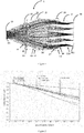
Figure 1 is an optical path diagram of an optical system according to a first embodiment of the present disclosure. -
Figure 2 is Modulation Transfer Function (MTF) graph of an optical system according to a first embodiment of the present disclosure. -
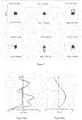
Figure 3 is spot diagrams of an optical system according to a first embodiment of the present disclosure. -
Figure 4a is field curve graph of an optical system according to a first embodiment of the present disclosure. -
Figure 4b is a distortion curve graph of an optical system according to a first embodiment of the present disclosure. -
Figure 5 is an optical path diagram of an optical system according to a second embodiment of the present disclosure. -
Figure 6 is Modulation Transfer Function (MTF) graph of an optical system according to a second embodiment of the present disclosure. -
Figure 7 is spot diagrams of an optical system according to a second embodiment of the present disclosure. -
Figure 8a is field curve graphs of an optical system according to a second embodiment of the present disclosure. -
Figure 8b is a distortion curve graph of an optical system according to a second embodiment of the present disclosure. -
Figure 9 is an optical path diagram of an optical system according to a third embodiment of the present disclosure. -
Figure 10 is Modulation Transfer Function (MTF) graph of an optical system according to a third embodiment of the present disclosure. -
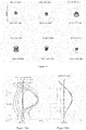
Figure 11 is spot diagrams of an optical system according to a third embodiment of the present disclosure. -
Figure 12a is field curve graph of an optical system according to a third embodiment of the present disclosure. -
Figure 12b is a distortion curve graph of an optical system according to a third embodiment of the present disclosure. - In order to make the objects, technical solutions and advantages of the present disclosure clearer, the present disclosure will be further described in detail below in combination with a plurality of embodiments and the accompanying drawings. It should be understood that the specific embodiments described herein are only used to explain the present disclosure rather than construed to limit the present disclosure.
- With reference to
Figure 1 , a schematic view is illustrated for anoptical system 1 according to a first embodiment of the present disclosure, which can be mounted at a head-mounted display apparatus (not shown in the diagram) together with adisplay unit 30. Theoptical system 1 includes adiaphragm 10, afirst lens 21, asecond lens 22, athird lens 23, afourth lens 24, afifth lens 25 and adisplay unit 30 arranged in order from a human-eye observation side to an image side at the display unit 30 (i.e., from left to right). In this embodiment,diaphragm 10 is an exit pupil for an image formed in the optical system and is a virtual light-exiting aperture. When human eyes are at thediaphragm 10, optimal images will be observed. In this embodiment, thefirst lens 21, thethird lens 23 and thefourth lens 24 each are a positive lens, and thesecond lens 22 and thefifth lens 25 each are a negative lens. - From the left to right as shown in
Figure 1 , a surface of thediaphragm 10 is numbered as F0, and similar numbering is given to individual surfaces of five lenses until a surface of thedisplay unit 30 is numbered as F11. Specifically, thefirst lens 21 has a surface F1 facing and bulging toward thediaphragm 10, with a positive curvature radius for the surface F1. Thesecond lens 22 has a surface F3 facing toward thefirst lens 21 and concaving toward thethird lens 23 and a surface F4 facing and bulging toward thethird lens 23. Curvature radiuses of the surface F3 and the surface F4 of thesecond lens 22 are negative. Thethird lens 23 has a surface F6 facing and bulging toward thefourth lens 24, with a negative curvature radius for the surface F6. Thefourth lens 24 has a surface F7 facing and bulging toward thethird lens 23 and a surface F8 facing toward thefifth lens 25 and concaving toward thethird lens 23. Curvature radius of the surface F7 is positive, while curvature radius of the surface F8 is negative. Thefifth lens 25 has a surface F10 facing toward thedisplay unit 30 and concaving toward thefourth lens 24 and a surface F9 facing toward the fourth lens 24 (where the surface F9 has two distal portions concaving toward thedisplay unit 30 at periphery away from an optical axis). Curvature radiuses of the surface F9 and the surface F10 are positive. - The
first lens 21 and thesecond lens 22 each are spherical, while thefourth lens 24 and thefifth lens 25 each are aspheric. The surface F5 of thethird lens 23 close to thesecond lens 22 is spherical; and surface F6 of thethird lens 23 close to thefourth lens 24 is aspheric. Thus, the optical system can reduce aberration more sufficiently. - In this embodiment, a focal distance of the first lens is f1, a focal distance of the second lens is f2, a focal distance of the third lens is f3, a focal distance of the fourth lens is f4, a focal distance of the fifth lens is f5, and a total focal distance of the optical system is ft, with the following formulas met:
- 1.5 < f1/ft < 3,
- -2 < f2/ft < -1.2,
- 2 < f3/ft < 2.5,
- 0.5 < f4/ft < 1.5, and
- -6 < f5/ft < -1.
- Specifically, referring to Table 1, it shows data associated with the optical system in the first embodiment of the present disclosure.
Table 1 Embodiment 1: exiting-hole diameter 7mm, effective focal length 19, field-of-view 2ω=51°, distance of exit pupil 13∼15mmSurf surf type Raduis(mm) Thickness(mm) Material nd vd F0 infinite 13∼15 F1 spheric 24 4.3 1.53 56 F2 spheric infinite 5.4 F3 spheric -15 2.7 1.64 24 F4 spheric -51 0.2 F5 spheric infinite 12 1.53 56 F6 aspheric -23 0.1 F7 aspheric 13 8 1.53 56 F8 aspheric -350 2.2 F9 aspheric 22 2.5 1.64 24 F10 aspheric 16 9.2 F11 infinite - Referring to Table 2, it shows data associated with the aspheric surfaces of the lenses in the first embodiment of the present disclosure.
Table 2 Surface K A2 A4 A6 A8 A10 A12 F6 -1.1E+00 0.0E+00 -2.5E-04 1.9E-06 -7.7E-09 1.5E-11 -1.1E-14 F7 -5.5E+00 0.0E+00 1.0E-04 -2.0E-06 1.8E-08 -7.1E-11 1.1E-13 F8 1.9E-01 0.0E+00 2.0E-04 -1.4E-06 3.0E-09 1.8E-12 -1.1E-14 F9 -4.5E+20 0.0E+00 4.2E-04 -4.5E-06 2.1E-08 -1.0E-10 2.9E-13 F10 -1.1E-01 0.0E+00 6.6E-04 -1.3E-05 1.0E-07 -4.1E-10 6.6E-13 - Referring to Table 3, it shows data associated with the focal distance of each lens in the first embodiment of the present disclosure.
Table 3 a focal distance of each lens a ratio of focal distance of each lens to total focal length of the optical system f1=45 f1/ft=2.368 f2=-34 f2/ft=-1.789 f3=43 f3/ft=2.263 f4=23 f4/ft=1.211 f5=19 f5/ft=-5.211 ft=19 - With reference to
Figure 2 , a diagram showing Modulation Transfer Function (MTF) is illustrated for the optical system according to the first embodiment of the present disclosure. The Modulation Transfer Function comprehensively reflects image quality of an optical system, with more smooth of a curve shape and higher of a Y-coordinate value (i.e., closer to 1) indicating better imaging quality of the optical system. It can be seen fromFigure 3 , where different image qualities under different image heights from 0.000 mm to 25.50 mm are depicted, the optical system has been corrected for aberration, characterized by smooth and compact MTF curves with high MTF values. -
Figure 3 shows spot diagrams of the optical system according to the first embodiment of the present disclosure. The spot diagram reflects geometric construction for an image formed in an optical system without consideration of diffraction. For an optical system with large aberration, spot distribution in the spot diagram approximately represents energy distribution of image points. Accordingly, density in a spot diagram can be used in evaluation of image quality, as it directly reflects or provides direct measurement on imaging quality of the optical system, with the smaller of a Root Mean Square (RMS) radius of the spot diagram indicating better imaging quality of the optical system. It can be seen from the spot diagrams inFigure 3 that spots formed are small under each field-of-view of the present optical system, which demonstrates energy distribution of the optical system is well optimized and aberration of the optical system is efficiently corrected. -
Figures 4(a) and 4(b) are two diagrams respectively showing field curvature and aberration of the optical system according to the first embodiment of the present disclosure. The field curvature is an aberration where an image of a flat surface of an object is formed on a curved surface, which is characterized by meridianal curvature and sagittal curvature of field, referring toFigure 4(a) , with the T curve representing the meridianal curvature of field and S curve representing the sagittal curvature of field, as well as resultant difference there between representing astigmatism of the present optical system. The field curvature and the astigmatism both are important aberrations that affect off-axial field-of-view lights in the optical system, e.g., the field curvature and the astigmatism at too high values affect imaging quality for off-axis field-of-view lights badly in the optical system. It can be seen that the field curvature and the astigmatism of the present optical system are both within a small range by correction. - Although not affecting clarity of an optical system, the aberration causes image deformation, which is extremely difficult to correct for a wide-angle lens and needs to be dealt with in image post-processing.
-
Figures 2 to 4 exhibit entirely characteristics of the optical system, such as wide field-of-view and high-image quality, in the first embodiment of the present disclosure. - With reference to
Figure 5 , a schematic view is illustrated for an optical system 2 according to a second embodiment of the present disclosure. The optical system 2 includes adiaphragm 10, afirst lens 21, asecond lens 22, athird lens 23, afourth lens 24, afifth lens 25 and adisplay unit 30 arranged in order from a human-eye observation side to an image side at the display unit 30 (i.e., from left to right). Thefirst lens 21, thethird lens 23 and thefourth lens 24 each are a positive lens, and thesecond lens 22 and thefifth lens 25 each are a negative lens. - From the left to right as shown in
Figure 5 , a surface of thediaphragm 10 is numbered as F0, and similar numbering is given to individual surfaces of five lenses until a surface of thedisplay unit 30 is numbered as F11. Specifically, thefirst lens 21 has a surface F1 facing and bulging toward thediaphragm 10 and a surface F2 facing toward thesecond lens 22. Curvature radius of the surface F1 is positive, while curvature radius of the surface F2 is negative. Thesecond lens 22 has a surface F3 facing toward thefirst lens 21 and concaving toward the third lens 23and a surface F4 facing and bulging toward thethird lens 23. Curvature radiuses of the surface F3 and the surface F4 of thesecond lens 22 are negative. Thethird lens 23 has a surface F6 facing and bulging toward thefourth lens 24, with a negative curvature radius for F6. Thefourth lens 24 has a surface F7 facing and bulging toward thethird lens 23 and a surface F8 facing toward thefifth lens 25 and concaving toward thethird lens 23. Curvature radiuses of the surface F7 and the surface F8 of thefourth lens 24 are positive. Thefifth lens 25 has a surface F10 facing toward thedisplay unit 30 and concaving toward thefourth lens 24 and a surface F9 facing and bulging toward thefourth lens 24. Curvature radiuses of the surface F9 and the surface F10 of thefifth lens 25 are positive. - In the second embodiment, the
first lens 21, thesecond lens 22, thethird lens 23, thefourth lens 24 and thefifth lens 25 each are aspheric, such that the optical system constituted by these five lenses is not only provided with well-corrected aberration and image distortion but also with lighter, thinner and flatter lens assembly. - In this embodiment, a focal distance of the first lens is f1, a focal distance of the second lens is f2, a focal distance of the third lens is f3, a focal distance of the fourth lens is f4, a focal distance of the fifth lens is f5, and a total focal distance of the optical system is ft, with the following formulas met:
- 1.5 < f1/ft < 3,
- -2 < f2/ft < -1.2,
- 2 < f3/ft < 2.5,
- 0.5 < f4/ft < 1.5, and
- -6 < f5/ft < -1.
- Specifically, referring to Table 4, it shows data associated with the optical system in the second embodiment of the present disclosure.
Table 4 Embodiment 2 : exiting-hole diameter 7mm, effective focal length 19mm, field-of-view 2ω=51°, distance of exit pupil 13∼15mmSurface surface type Raduis(mm) Thickness(mm) Material nd vd F0 infinite 13∼15 F1 aspheric 19 4.3 1.53 56 F2 aspheric -304 3.9 F3 aspheric -17 2 1.64 24 F4 aspheric -281 0.1 F5 aspheric infinite 8.7 1.53 56 F6 aspheric -25 0.1 F7 aspheric 7 5.4 1.53 56 F8 aspheric 24 1.2 F9 aspheric 105 1.9 1.64 24 F10 aspheric 17 8.1 F11 infinite - Referring to Table 5, it shows data associated with the aspheric surfaces for lenses in the second embodiment of the present disclosure.
Table 5 Sur K A2 A4 A6 A8 A10 A12 A14 A16 F1 9.1E-04 0.0E+00 -1.2E-06 -1.1E-06 1.8E-08 -1.4E-10 -4.2E-14 5.7E-15 -2.2E-17 F2 0.0E+00 0.0E+00 6.6E-35 8.1E-46 1.1E-46 1.5E-48 1.4E-50 1.3E-52 0.0E+00 F3 0.0E+00 0.0E+00 -1.4E-34 5.1E-45 -5.4E-47 -1.0E-48 -1.1E-50 -1.1E-52 0.0E+00 F4 -5.2E+04 0.0E+00 -4.7E+00 5.6E-08 6.9E-10 2.6E-12 -1.7E-14 -3.9E-16 1.8E-18 F5 0.0E+00 0.0E+00 -9.9E-35 -3.9E-46 -4.0E-48 -2.7E-50 -1.4E-52 -4.8E-55 0.0E+00 F6 -9.0E-01 0.0E+00 -7.5E-04 1.1E-05 -9.7E-08 4.7E-10 -1.2E-12 1.2E-15 2.5E-19 F7 -3.9E+00 0.0E+00 5.5E-04 -1.5E-05 1.9E-07 -1.3E-09 4.3E-12 -7.6E-15 1.7E-17 F8 -4.3E+00 0.0E+00 5.3E-04 -1.1E-05 2.3E-08 1.1E-09 -1.1E-11 2.8E-14 4.5E-17 F9 -4.5E+20 0.0E+00 1.1E-03 -1.8E-05 9.1E-08 5.2E-10 -7.8E-12 9.3E-15 1.2E-16 F10 -1.3E+00 0.0E+00 2.1E-03 -7.1E-05 1.3E-06 -1.4E-08 7.5E-11 -1.7E-13 0.0E+00 - Referring to Table 6, it shows data associated with the focal distance of each lens in the second embodiment of the present disclosure.
Table 6 a focal distance of each lens a ratio of focal distance of each lens to total focal length of the optical system f1=34 f1/ft=1.789 f2=-27 f2/ft=-1.421 f3=46 f3/ft=2.421 f4=17 f4/ft=0.895 f5=-32 f5/ft=-1.684 ft=19 - With reference to
Figure 6 , a diagram showing Modulation Transfer Function (MTF) is illustrated for the optical system according to the second embodiment of the present disclosure. It can be seen fromFigure 6 , where different image qualities under different image heights from 0.000 mm to 25.50 mm are depicted, the optical system has been corrected for aberration, characterized by smooth and compact MTF curves with high MTF values. -
Figure 7 shows spot diagrams of the optical system according to the second embodiment of the present disclosure. It can be seen from the spot diagrams that spots formed under light in each field-of-view all have small and uniform radiuses at a plat surface of an image (i.e., a display device I), and spots formed under lights with different wavelengths in one field-of-view are in low degree of dislocation, demonstrating efficiently corrected aberration for the optical system and an overall uniform display image with high optical property that observed from an eye lens of the optical system. -
Figures 8(a) and 8(b) are two diagrams respectively showing field curvature and aberration of the optical system according to the second embodiment of the present disclosure. It can be seen fromFigures 8(a) and 8(b) that the optical system in the second embodiment is provided with well-controlled field curvature, astigmatism and distortion, thus achieving wide field-of-view and high imaging quality. -
Figures 6 to 8 exhibit comprehensive characteristics of the optical system, such as wide field-of-view and high-image quality, in the second embodiment of the present disclosure. - With reference to
Figure 9 , a schematic view is illustrated for an optical system 3 according to a third embodiment of the present disclosure. The optical system 3 includes adiaphragm 10, afirst lens 21, asecond lens 22, athird lens 23, afourth lens 24, afifth lens 25 and adisplay unit 30 arranged in order from a human-eye observation side to an image side at the display unit 30 (i.e., from left to right), Thefirst lens 21, thethird lens 23 and thefourth lens 24 each are a positive lens, and thesecond lens 22 and thefifth lens 25 each are a negative lens. - From the left to right as shown in
Figure 9 , a surface of thediaphragm 10 is numbered as F0, and similar numbering is given to individual surfaces of five lenses until a surface of thedisplay unit 30 is numbered as F11. Specifically, thefirst lens 21 has a surface F1 facing and bulging toward thediaphragm 10 and a surface F2 facing toward thesecond lens 22 and concaving towards thediaphragm 10. Curvature radiuses of the surface F1 and the surface F1 of thefirst lens 21 are positive. Thesecond lens 22 has a surface F3 facing toward thefirst lens 21 and concaving toward thethird lens 23 . Curvature radiuses of the surface F3 and the surface F4 of thesecond lens 22 are negative. Thethird lens 23 has a surface F6 facing and bulging toward thefourth lens 24, with a negative curvature radius for the surface F6. Thefourth lens 24 has a surface F7 facing and bulging toward thethird lens 23, and a surface F8 facing toward thefifth lens 25 and bulging toward thethird lens 23. Curvature radius of the surface F7 is positive, while curvature radius of the surface F8 is negative. Thefifth lens 25 has a surface F9 facing toward thefourth lens 24 and concaving toward thedisplay unit 30, and a surface F10 facing toward thedisplay unit 30 and concaving toward thefourth lens 24. Curvature radiuses of the surface F9 and the surface F10 of thefifth lens 25 are negative. - The
first lens 21 and thesecond lens 22 each are spherical. The surface of thethird lens 23 facing toward thesecond lens 22 is spherical, while the surface of thethird lens 23 facing toward thefourth lens 24 is aspheric. Thefourth lens 24 and thefifth lens 25 each are aspheric. - In this embodiment, a focal distance of the first lens is f1, a focal distance of the second lens is f2, a focal distance of the third lens is f3, a focal distance of the fourth lens is f4, a focal distance of the fifth lens is f5, and a total focal distance of the optical system is ft, with the following formulas met:
- 1.5 < f1/ft < 3,
- -2 < f2/ft < -1.2,
- 2 < f3/ft < 2.5,
- 0.5 < f4/ft < 1.5, and
- -6 < f5/ft < -1.
- Specifically, referring to Table 7, it shows data associated with the optical system in the third embodiment of the present disclosure.
Table 7 Embodiment 3: exiting-hole diameter 7mm, effectivefocallength 19mm, field-of-view 2ω=51°, distance of exit pupil 13∼15mmSurface surface type Raduis(mm) Thickness(mm) Material nd vd F0 infinite 13∼15 F1 spheric 24 4 1.53 56 F2 spheric 160 5 F3 spheric -17 2.5 1.64 24 F4 spheric -400 0.2 F5 spheric infinite 7.5 1.53 56 F6 aspheric -24 0.1 F7 aspheric 17 16 1.53 56 F8 aspheric -9.6 1.3 F9 aspheric 30 2.8 1.59 30 F10 aspheric 8 7.5 F11 infinite - Referring to Table 8, it shows data associated with the aspheric surfaces of the lenses in the third embodiment of the present disclosure.
Table 8 Surface K A2 A4 A6 A8 A10 A12 F6 9.0E-01 0.0E+00 0.0E+00 -1.1E-07 5.5E-10 0.0E+00 0.0E+00 F7 -3.5E+00 0.0E+00 3.8E-05 -1.2E-07 4.3E-10 -9.5E-13 1.4E-15 F8 -4.0E+00 0.0E+00 3.4E-05 -9.1E-08 1.2E-10 0.0E+00 0.0E+00 F9 -1.3E+38 0.0E+00 -1.5E-04 1.1E-06 -2.9E-09 0.0E+00 0.0E+00 F10 -9.7E-01 0.0E+00 -3.0E-04 1.3E-06 -7.7E-11 0.0E+00 0.0E+00 - Referring to Table 9, it shows data associated with the focal distance of each lens in the third embodiment of the present disclosure.
Table 9 a focal distance of each lens a ratio of focal distance of each lens to total focal length of the optical system f1=53 f1/ft=2.789 f2=-28 f2/ft=-1.474 f3=45 f3/ft=2.368 f4=15 f4/ft=0.789 f5=-20 f5/ft=-1.053 ft=19 - With reference to
Figure 10 , a diagram showing Modulation Transfer Function (MTF) is illustrated for the optical system according to the third embodiment of the present disclosure. It can be seen fromFigure 3 , where different image qualities under different image heights from 0.000 mm to 25.50 mm are depicted, the optical system has been corrected for aberration, characterized by smooth and compact MTF curves with high MTF values. -
Figure 11 shows spot diagrams of the optical system according to the second embodiment of the present disclosure. It can be seen from the spot diagrams that spots formed under light in each field-of-view all have small and uniform radiuses at a plat surface of an image (i.e., a display device I), and spots formed under lights with different wavelengths in one field-of-view are in low degree of dislocation, demonstrating efficiently corrected aberration for the optical system and an overall uniform display image with high optical property that observed from an eye lens of the optical system. -
Figures 12(a) and 12(b) are two diagrams respectively showing field curvature and aberration of the optical system according to the third embodiment of the present disclosure. It can be seen fromFigures 12(a) and 12(b) that the optical system in the third embodiment is provided with well-controlled field curvature, astigmatism and distortion, thus achieving wide field-of-view and high imaging quality. -
Figures 9 to 12 exhibit comprehensive characteristics of the optical system, such as wide field-of-view and high-image quality, in the third embodiment of the present disclosure. - The foregoing descriptions are merely preferred embodiments of the present disclosure and are not intended to limit the present disclosure. Any modifications, equivalent replacements and alternatives made within the spirit and principle of the present disclosure will be included in the protection of the present disclosure.
Claims (10)
- An optical system, comprising a first lens, a second lens, a third lens, a fourth lens and a fifth lens in order arranged coaxially along an optical axis direction from a human-eye observation side to an image side at a display unit, wherein
the first lens is a positive lens with a focal distance f1,
the second lens is a negative lens with a focal distance f2,
the third lens is a positive lens with a focal distance f3,
the fourth lens is a positive lens with a focal distance f4,
the fifth lens is a negative lens with a focal distance f5, and
the optical system is of a total focal distance ft, with the following formulas met:1.5 < f1/ft < 3,-2 < f2/ft < -1.2,2 < f3/ft < 2.5,0.5 < f4/ft < 1.5, and-6 < f5/ft < -1. - The optical system according to claim 1, wherein the fourth lens and the fifth lens each are aspheric, and the third lens has an aspheric surface facing toward the fourth lens.
- The optical system according to claim 2, wherein the first lens and the second lens each are spherical, and the third lens has a spherical surface facing toward the second lens.
- The optical system according to claim 2, wherein the first lens and the second lens each are aspheric, and the third lens has an aspheric surface facing toward the second lens.
- The optical system according to claim 1, wherein the fourth lens has a surface facing and bulging toward the third lens.
- The optical system according to claim 5, wherein the fourth lens has a surface facing and bulging toward the fifth lens.
- The optical system according to claim 6, wherein the first lens has a surface facing toward a diaphragm and bulging toward the human-eye observation side.
- The optical system according to claim 7, wherein the second lens has a surface facing toward the first lens and concaving toward the third lens.
- The optical system according to claim 8, wherein the third lens has a surface facing and bulging toward the fourth lens.
- A head-mounted display apparatus, comprising a display unit and an optical system as defined in any one of claims 1 to 9, wherein the optical system is disposed between human eyes and the display unit.
Applications Claiming Priority (1)
| Application Number | Priority Date | Filing Date | Title |
|---|---|---|---|
| PCT/CN2016/099099 WO2018049616A1 (en) | 2016-09-14 | 2016-09-14 | Optical system, and head-mounted display apparatus employing same |
Publications (2)
| Publication Number | Publication Date |
|---|---|
| EP3514596A1 true EP3514596A1 (en) | 2019-07-24 |
| EP3514596A4 EP3514596A4 (en) | 2020-05-06 |
Family
ID=61618590
Family Applications (1)
| Application Number | Title | Priority Date | Filing Date |
|---|---|---|---|
| EP16916001.7A Withdrawn EP3514596A4 (en) | 2016-09-14 | 2016-09-14 | Optical system, and head-mounted display apparatus employing same |
Country Status (6)
| Country | Link |
|---|---|
| US (1) | US10558023B2 (en) |
| EP (1) | EP3514596A4 (en) |
| JP (1) | JP2019529987A (en) |
| KR (1) | KR20190018719A (en) |
| CN (1) | CN108064352A (en) |
| WO (1) | WO2018049616A1 (en) |
Families Citing this family (10)
| Publication number | Priority date | Publication date | Assignee | Title |
|---|---|---|---|---|
| US10634913B2 (en) * | 2018-01-22 | 2020-04-28 | Symbol Technologies, Llc | Systems and methods for task-based adjustable focal distance for heads-up displays |
| EP3809184A4 (en) * | 2019-07-29 | 2021-04-21 | Shenzhen Nade Optical Co., Ltd. | OCULAR AND HEADSET OPTICAL SYSTEM |
| CN111308709B (en) * | 2020-02-26 | 2022-02-22 | 歌尔光学科技有限公司 | Optical system and augmented reality device |
| CN112114418B (en) * | 2020-09-24 | 2023-08-15 | 玉晶光电(厦门)有限公司 | Optical lens group |
| CN111880363B (en) * | 2020-09-28 | 2024-04-05 | 歌尔股份有限公司 | Optical machines and AR equipment |
| WO2022213381A1 (en) * | 2021-04-09 | 2022-10-13 | 深圳市大疆创新科技有限公司 | Optical system and video glasses |
| CN116009190B (en) * | 2021-10-21 | 2025-11-25 | 成都理想境界科技有限公司 | Optical imaging lens assembly, scanning display device and near-eye display device |
| CN117539035B (en) * | 2024-01-09 | 2024-04-05 | 长春理工大学 | Side view method and lens of cell factory bioreactor |
| WO2025215769A1 (en) * | 2024-04-10 | 2025-10-16 | 日精テクノロジー株式会社 | Projection optical system and head-mounted display |
| CN119376072B (en) * | 2024-12-30 | 2025-05-09 | 江西联昊光电有限公司 | Optical lens and near-eye display device |
Family Cites Families (19)
| Publication number | Priority date | Publication date | Assignee | Title |
|---|---|---|---|---|
| JPS6048014B2 (en) * | 1978-05-25 | 1985-10-24 | オリンパス光学工業株式会社 | wide field eyepiece |
| JP3729218B2 (en) * | 1996-07-24 | 2005-12-21 | 株式会社ニコン | Eyepiece |
| JPH11133315A (en) * | 1997-10-29 | 1999-05-21 | Sony Corp | Eyepiece and virtual image providing device |
| JP3524408B2 (en) * | 1998-01-06 | 2004-05-10 | キヤノン株式会社 | Observation optical system and optical apparatus having the same |
| JPH11271639A (en) * | 1998-01-20 | 1999-10-08 | Olympus Optical Co Ltd | Stereoscopic microscope |
| US8437472B2 (en) | 2009-02-27 | 2013-05-07 | Red Hat, Inc. | Strengthened key schedule for arcfour |
| TWI436089B (en) | 2011-08-04 | 2014-05-01 | Largan Precision Co Ltd | Image capturing optical lens assembly |
| JP5839038B2 (en) * | 2011-08-19 | 2016-01-06 | コニカミノルタ株式会社 | Imaging lens and imaging apparatus |
| TWI434064B (en) | 2011-10-25 | 2014-04-11 | Largan Precision Co Ltd | Photographing optical lens system |
| KR101364975B1 (en) | 2012-03-19 | 2014-02-20 | 주식회사 코렌 | Photographic lens optical system |
| WO2013172164A1 (en) | 2012-05-14 | 2013-11-21 | コニカミノルタ株式会社 | Image-capturing lens |
| JP2014056021A (en) * | 2012-09-11 | 2014-03-27 | Ricoh Imaging Co Ltd | Ocular lens system |
| JP6048882B2 (en) | 2013-02-28 | 2016-12-21 | 株式会社オプトロジック | Imaging lens |
| TWI493221B (en) | 2014-03-14 | 2015-07-21 | Glory Science Co Ltd | Optical lens system |
| CN104914558B (en) * | 2014-03-14 | 2017-09-01 | 光燿科技股份有限公司 | Imaging lens group |
| CN104570286B (en) | 2014-12-08 | 2017-06-27 | 青岛歌尔声学科技有限公司 | A miniature fisheye lens and a head-mounted display device |
| CN105278109B (en) * | 2015-07-10 | 2017-11-28 | 深圳纳德光学有限公司 | Big angle of visual field eyepiece optical system |
| TWI598628B (en) * | 2016-02-16 | 2017-09-11 | 先進光電科技股份有限公司 | Optical image capturing system |
| CN108375829B (en) * | 2016-04-29 | 2020-11-13 | 南京希亘数字技术有限公司 | Optical eyepiece lens with excellent imaging quality and head-mounted display device |
-
2016
- 2016-09-14 JP JP2019513367A patent/JP2019529987A/en active Pending
- 2016-09-14 WO PCT/CN2016/099099 patent/WO2018049616A1/en not_active Ceased
- 2016-09-14 KR KR1020197001709A patent/KR20190018719A/en not_active Ceased
- 2016-09-14 EP EP16916001.7A patent/EP3514596A4/en not_active Withdrawn
- 2016-09-14 US US16/063,490 patent/US10558023B2/en not_active Expired - Fee Related
- 2016-09-14 CN CN201680034169.6A patent/CN108064352A/en not_active Withdrawn
Also Published As
| Publication number | Publication date |
|---|---|
| US20190072747A1 (en) | 2019-03-07 |
| WO2018049616A1 (en) | 2018-03-22 |
| CN108064352A (en) | 2018-05-22 |
| KR20190018719A (en) | 2019-02-25 |
| US10558023B2 (en) | 2020-02-11 |
| EP3514596A4 (en) | 2020-05-06 |
| JP2019529987A (en) | 2019-10-17 |
Similar Documents
| Publication | Publication Date | Title |
|---|---|---|
| US10558023B2 (en) | Optical system and head-mounted display apparatus using same | |
| CN107683432B (en) | Eyepiece optical system and head-mounted display device with large field of view | |
| US11199682B2 (en) | Imaging optical system and image capturing apparatus | |
| US5677797A (en) | Method for correcting field curvature | |
| TWI403781B (en) | Photographing optical lens assembly | |
| US20170059832A1 (en) | Single focal length lens system, interchangeable lens apparatus, and camera system | |
| US7443612B2 (en) | Compact large aperture wide-angle lens and camera including compact large aperture wide-angle lens | |
| TW201245758A (en) | Optical image capturing lens system | |
| US20180052383A1 (en) | Ocular lens and imaging apparatus | |
| WO2021016810A1 (en) | Eyepiece optical system and head-mounted display | |
| CN115220215B (en) | Optical imaging lens | |
| JP6431588B1 (en) | Imaging lens | |
| JP5387139B2 (en) | Imaging lens, camera device, and portable information terminal device | |
| JP2017111260A (en) | Microscope objective lens | |
| CN105892056B (en) | A kind of relay optical system shown for head | |
| EP3702824B1 (en) | Head mounted display device with eyepiece | |
| JP7433875B2 (en) | Optical system and imaging device | |
| JP2014056021A (en) | Ocular lens system | |
| JPH06300965A (en) | Wide-angle lens | |
| CN108463761B (en) | Eyepiece optical system and head-mounted display device for near-eye display | |
| CN112424669A (en) | Eyepiece optical system and head-mounted display | |
| CN113433662B (en) | Imaging system, lens module, electronic equipment and carrier | |
| CN115291368A (en) | Objective lens system and optical system | |
| CN107076965A (en) | Endoscope objective optical system | |
| CN114384677A (en) | Objective lens for endoscope and endoscope |
Legal Events
| Date | Code | Title | Description |
|---|---|---|---|
| STAA | Information on the status of an ep patent application or granted ep patent |
Free format text: STATUS: THE INTERNATIONAL PUBLICATION HAS BEEN MADE |
|
| PUAI | Public reference made under article 153(3) epc to a published international application that has entered the european phase |
Free format text: ORIGINAL CODE: 0009012 |
|
| STAA | Information on the status of an ep patent application or granted ep patent |
Free format text: STATUS: REQUEST FOR EXAMINATION WAS MADE |
|
| 17P | Request for examination filed |
Effective date: 20180618 |
|
| AK | Designated contracting states |
Kind code of ref document: A1 Designated state(s): AL AT BE BG CH CY CZ DE DK EE ES FI FR GB GR HR HU IE IS IT LI LT LU LV MC MK MT NL NO PL PT RO RS SE SI SK SM TR |
|
| AX | Request for extension of the european patent |
Extension state: BA ME |
|
| DAV | Request for validation of the european patent (deleted) | ||
| DAX | Request for extension of the european patent (deleted) | ||
| A4 | Supplementary search report drawn up and despatched |
Effective date: 20200403 |
|
| RIC1 | Information provided on ipc code assigned before grant |
Ipc: G02B 13/00 20060101ALI20200330BHEP Ipc: G02B 11/30 20060101ALI20200330BHEP Ipc: G02B 9/60 20060101AFI20200330BHEP Ipc: G02B 27/01 20060101ALI20200330BHEP |
|
| STAA | Information on the status of an ep patent application or granted ep patent |
Free format text: STATUS: THE APPLICATION IS DEEMED TO BE WITHDRAWN |
|
| 18D | Application deemed to be withdrawn |
Effective date: 20201103 |