EP3514550A1 - Pcr tube, rfid specimen managing system, and rfid specimen managing method - Google Patents
Pcr tube, rfid specimen managing system, and rfid specimen managing method Download PDFInfo
- Publication number
- EP3514550A1 EP3514550A1 EP17850707.5A EP17850707A EP3514550A1 EP 3514550 A1 EP3514550 A1 EP 3514550A1 EP 17850707 A EP17850707 A EP 17850707A EP 3514550 A1 EP3514550 A1 EP 3514550A1
- Authority
- EP
- European Patent Office
- Prior art keywords
- cell
- rfid
- tube body
- pcr
- tube
- Prior art date
- Legal status (The legal status is an assumption and is not a legal conclusion. Google has not performed a legal analysis and makes no representation as to the accuracy of the status listed.)
- Granted
Links
Images





Classifications
-
- G—PHYSICS
- G01—MEASURING; TESTING
- G01N—INVESTIGATING OR ANALYSING MATERIALS BY DETERMINING THEIR CHEMICAL OR PHYSICAL PROPERTIES
- G01N35/00—Automatic analysis not limited to methods or materials provided for in any single one of groups G01N1/00 - G01N33/00; Handling materials therefor
- G01N35/00584—Control arrangements for automatic analysers
- G01N35/00722—Communications; Identification
- G01N35/00732—Identification of carriers, materials or components in automatic analysers
-
- B—PERFORMING OPERATIONS; TRANSPORTING
- B01—PHYSICAL OR CHEMICAL PROCESSES OR APPARATUS IN GENERAL
- B01L—CHEMICAL OR PHYSICAL LABORATORY APPARATUS FOR GENERAL USE
- B01L3/00—Containers or dishes for laboratory use, e.g. laboratory glassware; Droppers
- B01L3/54—Labware with identification means
- B01L3/545—Labware with identification means for laboratory containers
- B01L3/5453—Labware with identification means for laboratory containers for test tubes
-
- B—PERFORMING OPERATIONS; TRANSPORTING
- B01—PHYSICAL OR CHEMICAL PROCESSES OR APPARATUS IN GENERAL
- B01L—CHEMICAL OR PHYSICAL LABORATORY APPARATUS FOR GENERAL USE
- B01L3/00—Containers or dishes for laboratory use, e.g. laboratory glassware; Droppers
- B01L3/54—Labware with identification means
- B01L3/545—Labware with identification means for laboratory containers
- B01L3/5457—Labware with identification means for laboratory containers for container closures
-
- C—CHEMISTRY; METALLURGY
- C12—BIOCHEMISTRY; BEER; SPIRITS; WINE; VINEGAR; MICROBIOLOGY; ENZYMOLOGY; MUTATION OR GENETIC ENGINEERING
- C12M—APPARATUS FOR ENZYMOLOGY OR MICROBIOLOGY; APPARATUS FOR CULTURING MICROORGANISMS FOR PRODUCING BIOMASS, FOR GROWING CELLS OR FOR OBTAINING FERMENTATION OR METABOLIC PRODUCTS, i.e. BIOREACTORS OR FERMENTERS
- C12M1/00—Apparatus for enzymology or microbiology
-
- G—PHYSICS
- G01—MEASURING; TESTING
- G01N—INVESTIGATING OR ANALYSING MATERIALS BY DETERMINING THEIR CHEMICAL OR PHYSICAL PROPERTIES
- G01N35/00—Automatic analysis not limited to methods or materials provided for in any single one of groups G01N1/00 - G01N33/00; Handling materials therefor
- G01N35/02—Automatic analysis not limited to methods or materials provided for in any single one of groups G01N1/00 - G01N33/00; Handling materials therefor using a plurality of sample containers moved by a conveyor system past one or more treatment or analysis stations
- G01N35/026—Automatic analysis not limited to methods or materials provided for in any single one of groups G01N1/00 - G01N33/00; Handling materials therefor using a plurality of sample containers moved by a conveyor system past one or more treatment or analysis stations having blocks or racks of reaction cells or cuvettes
-
- G—PHYSICS
- G06—COMPUTING OR CALCULATING; COUNTING
- G06K—GRAPHICAL DATA READING; PRESENTATION OF DATA; RECORD CARRIERS; HANDLING RECORD CARRIERS
- G06K19/00—Record carriers for use with machines and with at least a part designed to carry digital markings
- G06K19/06—Record carriers for use with machines and with at least a part designed to carry digital markings characterised by the kind of the digital marking, e.g. shape, nature, code
- G06K19/067—Record carriers with conductive marks, printed circuits or semiconductor circuit elements, e.g. credit or identity cards also with resonating or responding marks without active components
- G06K19/07—Record carriers with conductive marks, printed circuits or semiconductor circuit elements, e.g. credit or identity cards also with resonating or responding marks without active components with integrated circuit chips
- G06K19/077—Constructional details, e.g. mounting of circuits in the carrier
- G06K19/07749—Constructional details, e.g. mounting of circuits in the carrier the record carrier being capable of non-contact communication, e.g. constructional details of the antenna of a non-contact smart card
- G06K19/07758—Constructional details, e.g. mounting of circuits in the carrier the record carrier being capable of non-contact communication, e.g. constructional details of the antenna of a non-contact smart card arrangements for adhering the record carrier to further objects or living beings, functioning as an identification tag
-
- G—PHYSICS
- G06—COMPUTING OR CALCULATING; COUNTING
- G06K—GRAPHICAL DATA READING; PRESENTATION OF DATA; RECORD CARRIERS; HANDLING RECORD CARRIERS
- G06K19/00—Record carriers for use with machines and with at least a part designed to carry digital markings
- G06K19/06—Record carriers for use with machines and with at least a part designed to carry digital markings characterised by the kind of the digital marking, e.g. shape, nature, code
- G06K19/067—Record carriers with conductive marks, printed circuits or semiconductor circuit elements, e.g. credit or identity cards also with resonating or responding marks without active components
- G06K19/07—Record carriers with conductive marks, printed circuits or semiconductor circuit elements, e.g. credit or identity cards also with resonating or responding marks without active components with integrated circuit chips
- G06K19/077—Constructional details, e.g. mounting of circuits in the carrier
- G06K19/07749—Constructional details, e.g. mounting of circuits in the carrier the record carrier being capable of non-contact communication, e.g. constructional details of the antenna of a non-contact smart card
- G06K19/07773—Antenna details
-
- G—PHYSICS
- G06—COMPUTING OR CALCULATING; COUNTING
- G06K—GRAPHICAL DATA READING; PRESENTATION OF DATA; RECORD CARRIERS; HANDLING RECORD CARRIERS
- G06K7/00—Methods or arrangements for sensing record carriers, e.g. for reading patterns
- G06K7/10—Methods or arrangements for sensing record carriers, e.g. for reading patterns by electromagnetic radiation, e.g. optical sensing; by corpuscular radiation
- G06K7/10009—Methods or arrangements for sensing record carriers, e.g. for reading patterns by electromagnetic radiation, e.g. optical sensing; by corpuscular radiation sensing by radiation using wavelengths larger than 0.1 mm, e.g. radio-waves or microwaves
- G06K7/10366—Methods or arrangements for sensing record carriers, e.g. for reading patterns by electromagnetic radiation, e.g. optical sensing; by corpuscular radiation sensing by radiation using wavelengths larger than 0.1 mm, e.g. radio-waves or microwaves the interrogation device being adapted for miscellaneous applications
-
- B—PERFORMING OPERATIONS; TRANSPORTING
- B01—PHYSICAL OR CHEMICAL PROCESSES OR APPARATUS IN GENERAL
- B01L—CHEMICAL OR PHYSICAL LABORATORY APPARATUS FOR GENERAL USE
- B01L2300/00—Additional constructional details
- B01L2300/02—Identification, exchange or storage of information
- B01L2300/021—Identification, e.g. bar codes
-
- B—PERFORMING OPERATIONS; TRANSPORTING
- B01—PHYSICAL OR CHEMICAL PROCESSES OR APPARATUS IN GENERAL
- B01L—CHEMICAL OR PHYSICAL LABORATORY APPARATUS FOR GENERAL USE
- B01L2300/00—Additional constructional details
- B01L2300/04—Closures and closing means
-
- B—PERFORMING OPERATIONS; TRANSPORTING
- B01—PHYSICAL OR CHEMICAL PROCESSES OR APPARATUS IN GENERAL
- B01L—CHEMICAL OR PHYSICAL LABORATORY APPARATUS FOR GENERAL USE
- B01L2300/00—Additional constructional details
- B01L2300/08—Geometry, shape and general structure
- B01L2300/0832—Geometry, shape and general structure cylindrical, tube shaped
-
- G—PHYSICS
- G01—MEASURING; TESTING
- G01N—INVESTIGATING OR ANALYSING MATERIALS BY DETERMINING THEIR CHEMICAL OR PHYSICAL PROPERTIES
- G01N35/00—Automatic analysis not limited to methods or materials provided for in any single one of groups G01N1/00 - G01N33/00; Handling materials therefor
- G01N35/00584—Control arrangements for automatic analysers
- G01N35/00722—Communications; Identification
- G01N35/00732—Identification of carriers, materials or components in automatic analysers
- G01N2035/00742—Type of codes
- G01N2035/00782—Type of codes reprogrammmable code
-
- G—PHYSICS
- G01—MEASURING; TESTING
- G01N—INVESTIGATING OR ANALYSING MATERIALS BY DETERMINING THEIR CHEMICAL OR PHYSICAL PROPERTIES
- G01N35/00—Automatic analysis not limited to methods or materials provided for in any single one of groups G01N1/00 - G01N33/00; Handling materials therefor
- G01N35/02—Automatic analysis not limited to methods or materials provided for in any single one of groups G01N1/00 - G01N33/00; Handling materials therefor using a plurality of sample containers moved by a conveyor system past one or more treatment or analysis stations
- G01N35/04—Details of the conveyor system
- G01N2035/0401—Sample carriers, cuvettes or reaction vessels
- G01N2035/0418—Plate elements with several rows of samples
Definitions
- the present invention relates to a PCR tube, an RFID sample management system, and an RFID sample management method, and particularly, to a PCR tube having an RFID, and an RFID sample management system and an RFID sample management method using this PCR tube.
- fractionating the target cell is performed by flow cytometry.
- the flow cytometry is a method of dispersing cells in a fluid, allowing the fluid to flow finely, optically analyzing the cells, and performing determination and preparative isolation of a cell to be acquired on the basis of this analysis result.
- the fractionated cell is then analyzed.
- the percentage of target cells during preparative isolation using the flow cytometry is about 70 percent to about 80 percent. For that reason, it is inefficient to perform analysis or pretreatment for analysis to all cells fractionated by the flow cytometry.
- sample management is essential so that samples are not confused.
- a method using a radio frequency identification (RFID) tag is performed.
- RFID radio frequency identification
- PCR polymerase chain reaction
- JP2002-082120A a living organism/biological sample container in which an integrated circuit (IC) chip is buried within the container is described.
- containers for analyzing cells need only to be capable of containing one cell and are small containers. Therefore, it is difficult to describe a lot of information in each container. Additionally, in a case where the RFID tag is installed, the size of the related-art containers is large. Additionally, in the PCR tube or the like, in a case where the PCR processing is performed, a temperature is applied. Therefore, a place where the RFID tag is installed is limited.
- the invention has been made in view of such circumstances, and an object thereof is to provide a PCR tube that can reliably perform sample management within the PCR tube, an RFID sample management system, and an RFID sample management method.
- a PCR tube related to the invention comprises a tube body that has an opening at one end and has a collar part around the opening; and a lid part that is attachably and detachably mounted on the tube body and seals the opening of the tube body at the time of mounting.
- An RFID tag having a passive antenna built therein is provided at the collar part or the lid part. The antenna has directivity in a direction opposite to a bottom face of the tube body.
- the RFID tag is provided at the collar part of the tube body, or the lid part. Accordingly, even in a case where PCR processing is performed using the PCR tube, a temperature can be prevented from being applied to the RFID tag, and management of the information stored in the RFID tag can be reliably performed. Additionally, by making the antenna of the RFID tag have the directivity in the direction opposite to the bottom face of the tube body, the reader/writer is installed on side opposite to the bottom face of the tube body in a case where the information of the RFID tag is read by the reader/writer. Accordingly, a distance from the RFID tag can be shortened and the information of the RFID tag can be read. Hence, even in a case where the antenna is short and the range of the directivity is narrow, the reading can be made by the reader/writer. Thus, the RFID tag can be made small and the installation of the RFID tag to the collar part or the lid part is possible.
- the bottom face of the tube body indicates a face that is in contact with the cell in a case where cell observation and the PCR processing are performed within the PCR tube.
- the PCR tube further comprises a positioning part that determines a position of the RFID tag in a case where the tube body is disposed on a well plate.
- the positioning part in a case where the tube body is disposed in the well plate is provided. Accordingly, the positions of the RFID tags of a plurality of the PCR tubes disposed in the well plate can be the same position. Hence, the information can be reliably read without erroneously reading the RFID tag of the next PCR tube in a case where the reading is made by the reader/writer.
- the positioning part is a notch part provided in the collar part.
- the notch part provided in the collar part is used as the positioning part.
- alignment of the PCR tube can be easily performed by providing a protrusion on the well plate and combining the protrusion with the notch part.
- the RFID tag provided at the lid part is attachable and detachable.
- the RFID tag provided at the lid part is made attachable and detachable. Accordingly, the RFID tag can be reused and costs can be reduced.
- the RFID tag is disposed within a structural body made of a light-transmissive material, and the lid part has a recess to which the structural body is attachable in a fitting manner.
- the recess into which the structural body having the RFID tag at the lid part can be fitted is provided. Accordingly, exchange of the structural body can be easily performed. Additionally, by forming the structural body from the light-transmissive material, the sample within the PCR tube can be imaged.
- the light-transmissive material is a material selected from polypropylene, polystyrene, and acrylic resin.
- This aspect describes specific examples of the light-transmissive material, and the sample within the PCR tube can be imaged by using the above materials.
- a code configured in one dimension or two dimensions is described in the tube body.
- the code configured in one dimension or two dimensions is described in the tube body. Accordingly, the information can be individually read by a code reader. Additionally, in a case where the information cannot be read due to a failure of the RFID tag, the information is read from the code configured in one dimension or two dimensions. Accordingly, the sample can be managed.
- PCR tube related to the invention it is preferable that at least any one of information of the cell or arrangement information of the tube body on the well plate is described in the tube body.
- the information of the cell or the arrangement information of the tube body on the well plate is described. Accordingly, the sample within the PCR tube can be visually checked, without performing the reading with a reader.
- an RFID sample management system of the invention comprises the PCR tube described above; a well plate having a well holder in which the PCR tube is disposed; and an RFID reader/writer that has a reader/writer antenna and is capable of being disposed on a side opposite to the bottom face of the tube body.
- the PCR tube described above is used. Accordingly, the directivity of the antenna of the RFID tag provided in the PCR tube is the side opposite to the bottom face of the tube body.
- a plurality of the reader/writer antennas are provided and the plurality of reader/writer antennas are disposed at positions corresponding to the well holders of the well plate.
- the reader/writer antennas provided in the reader/writer are respectively disposed at the positions corresponding to the well holders of the well plate. Accordingly, the information of the plurality of RFID tags can be read at a time.
- the system further comprises scanning means for scanning the RFID reader/writer.
- the scanning means for scanning the RFID reader/writer is provided to scan the RFID reader/writer. Accordingly, the information of the RFID tags of the plurality of PCR tubes can be read. Additionally, in a case where the read information is made by the RFID reader/writer, the read information is information of a PCR tube under the RFID reader/writer. Therefore, the read information and the sample within the PCR tube can be reliably made to correspond to each other and can be prevented from being erroneously recognized.
- the system further comprises determination means for determining whether or not next processing of a cell within the tube body is to be performed; and display means for displaying the cell determined to be subjected to the next processing by the determination means.
- the display means for displaying a cell determined to be subjected to processing next to the cell within the tube body is provided. Accordingly, even in a case where the RFID reader/writer is moved from a state where the RFID tag is read, a PCR tube containing a cell on which the next processing is performed can be checked.
- the display means is provided on the bottom face side of the tube body.
- the display means is provided on the bottom face side of the tube body. Accordingly, the PCR tube having the cell on which processing is performed can be visually and easily checked.
- the PCR reader/writer is disposed on the side opposite to the bottom face of the tube body in a case where the information is read from the RFID tag. Hence, in a case where the PCR tube is taken out from the well plate, the PCR reader/writer should be moved.
- an RFID sample management method related to the invention comprises a first writing step of writing at least any one of information of a cell to be fractionated or arrangement information of a tube body disposed on a well plate, in the RFID tag of the PCR tube described above; a step of fractionating the cell in the PCR tube disposed on the well plate; a step of imaging the fractionated cell and acquiring a cell image; a step of sorting a target cell on the basis of the cell image; a step of reading the information from the RFID tag of the PCR tube with an RFID reader/writer disposed on a side opposite the bottom face of the tube body; and a second writing step of writing information of the target cell in the RFID tag of the PCR tube.
- the RFID tag is disposed at the collar part of the tube body, or the lid part, by using the PCR tube described above. Therefore, even in a case where the PCR processing is performed, the information can be managed without breaking the recording of the RFID tag. Additionally, in a case where the information is read from the RFID tag by the RFID reader/writer or also in a case where the information is written in the RFID tag, the RFID reader/writer is disposed on the side opposite to the bottom face of the tube body of the PCR tube, the distance between the RFID tag and the RFID reader/writer can be shortened, and the size of the RFID tag can be made small.
- the RFID tag is made small even in a case where the RFID tag is used for the PCR tube. Accordingly, the RFID tag can be installed at the position where a temperature is not applied by the PCR processing. Thus, the RFID tag can be can installed in the PCR tube, and from the step of fractionating the cell, in the step of imaging the fractionated cell and the step of sorting the target cell, and also in the subsequent processing, the cell (sample) can be managed by the RFID tag.
- the method further comprises a code printing step of describing a code configured in one dimension or two dimensions in the tube body before the step of fractionating the cell.
- the code configured in one dimension or two dimensions is described in the tube body. Accordingly, the information can be individually read by a code reader. Additionally, in a case where the information cannot be read due to a failure of the RFID tag, the information is read from the code configured in one dimension or two dimensions. Accordingly, the sample can be managed.
- preferable one-dimensional codes for example, CODE 39, NW7, and CODE 128 can be used, and as preferable two-dimensional codes, for example, a quick response (QR) code (Registered Trademark), DataMatrixCode, VeriCode, an RFD417 code, and a CODE49 code can be used. Moreover, it is more preferable to use DataMatrixCode.
- QR quick response
- the method further comprises a character printing step of describing at least any one of the information of the cell or the arrangement information of the tube body on the well plate, in the tube body, before the step of fractionating the cell.
- the information of the cell or the arrangement information of the tube body on the well plate is described. Accordingly, the sample within the PCR tube can be visually checked, without performing the reading with a reader.
- a display means is provided at a position that faces each tube body, and the method further comprises a step of turning on the display means corresponding to the tube body to which the target cell sorted in the sorting step is fractionated.
- the display means corresponding to the tube body to which the target cell sorted in the sorting step is fractionated is turned on. Accordingly, after the PCR reader/writer is moved, the PCR tube including the target cell can be can be visually checked. Hence, the PCR tube having the cell to be processed can be taken out from the well plate without erroneous reading.
- the RFID tag in which the passive antenna having the directivity in the direction opposite to the bottom face of the tube body, that is, upward directivity, is built is provided at the collar part of the PCR tube, or the lid part. Accordingly, reading can be made from above the PCR tube by the reader/writer.
- a temperature can be effectively applied to the PCR tube in the case of the PCR processing.
- the RFID tag can be made small. Hence, also in a small-sized PCR tube, information management can be reliably performed using the RFID tag.
- the information is recorded on the RFID tag. Accordingly, even in the subsequent step, a sample within a PCR tube can be managed.
- Fig. 1 is a cross-sectional view illustrating an example of the shape of a PCR tube 40 used in the present embodiment
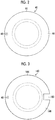
- Fig. 2 is a plan view of the PCR tube 40.
- the PCR tube 40 illustrated in Fig. 1 is a PCR tube that can be used for imaging of a cell fractionated in the PCR tube 40, using an analysis device 10 illustrated in Fig. 4 to be described below and also for a device that acquires optical information from the cell.
- the PCR tube 40 includes a tube body 42, and a lid part 44 on which the tube body 42 is attachably and detachably mounted.
- the tube body 42 has an opening at one end, and has a collar part 46 around this opening. Additionally, the lid part 44 seals the opening of the tube body 42 in a case where the tube body 42 is mounted.
- An RFID tag 48 is disposed in the collar part 46, and a sample (cell) within the PCR tube 40 is managed by the RFID tag 48.
- the collar part can also be referred to as a flange part.
- information of the cell within the PCR tube 40, positional information of a well plate, and the like are stored in the RFID tag 48.
- information of the cell and the positional information of the well plate information can be managed also in a case where the PCR tube 40 is moved from the well plate 19.
- the RFID tag 48 is constituted of an IC chip and an antenna.
- the antenna built in the RFID tag 48 is a passive antenna, and has directivity in a direction opposite to a bottom face 42a of the tube body 42, that is, upward directivity in Fig 1 .
- an RFID reader/writer disposed in a case where information is written in the RFID tag or information is read can be disposed close to an upper side of the PCR tube 40. Since the antenna built in the RFID tag can be downsized by disposing the RFID tag 48 and the RFID reader/writer close to each other, the RFID tag 48 itself can be downsized.
- the RFID tag 48 By downsizing the RFID tag 48, the RFID tag 48 can be installed also in a small container like the PCR tube 40. Additionally, in the PCR tube 40, it is necessary to apply a temperature in order to PCR-process the cell within the PCR tube 40. Hence, in a case where the RFID tag is disposed on a side face or a bottom face of the tube body, there is a case where heat may be applied the PCR processing, the RFID tag may be broken, and information may not be readable. By downsizing the RFID tag 48, since the RFID tag 48 can be installed in the collar part 46, the RFID tag 48 can reliably perform the management of the cell. The RFID tag 48 can be installed in the collar part 46 of the tube body 42 by an embedding method. The size of the RFID tag 48 can be a size of 1 mm x 1 mm x 0.15 mm (thickness).
- Fig. 3 is a plan view illustrating a modification example of a PCR tube 140 having the RFID tag 48 in the collar part.
- the PCR tube 140 illustrated in Fig. 3 has a positioning part that determines the position of the RFID tag 48 in a case where the tube body is disposed on the well plate.
- a collar part 146 of the tube body and a lid part 144 can be provided with a notch part 150.
- the position of the RFID tag 48 of each PCR tube on the well holder 18 can be the same position.
- the RFID reader/writer is brought close to the upper side of the PCR tube, so that the antenna of the RFID tag 48 can be downsized and the RFID tag 48 itself can be downsized.
- the PCR tube is not provided with the positioning part, it is conceivable that an antenna part of the RFID reader/writer and an antenna part of the RFID tag are separated from each other by the distance of the outer shape of the PCR tube.
- an RFID tag of a PCR tube next to the RFID tag of the above PCR tube to be originally read may be read.
- Accurate management of the sample cannot be performed in a case where the RFID tag of the next PCR tube is read.
- the antenna of the RFID reader/writer can be disposed at an upper part of the antenna of the RFID tag of each PCR tube. Accordingly, the RFID reader/writer can be prevented from erroneously reading information of a different RFID tag.
- a QR code or a data matrix code is described in a PCR tube body of the PCR tube.
- the RFID tag simultaneously reads a plurality of PCR tubes with the reader/writer, as will be described below.
- the QR code and/or the data matrix code can be individually read, and information can be easily read.
- the QR code and/or the data matrix code can be described by printing by an ink jet printer or marking by a laser marker.
- the tube body In order to read the information of the RFID tag, the reader/writer is required, and a code reader is also required in order to read the QR code or the data matrix.
- the information of the cell or the arrangement information on the well plate in the tube body without requiring reading the RFID tag, the QR code or the data matrix code, the information of the PCR tube and the cell within the PCR tube can be checked.
- the printing by the ink jet printer or the marking by the laser marker may be performed similarly to a case where the QR code and/or the data matrix code are described. Additionally, the information of the cell or the arrangement information may be described on a seal and pasted.
- the outer shape of the tube body 42 is a shape in which the tube body is capable of being loaded on a device that performs PCR processing, preferably, a PCR thermal cycler.
- a device that performs PCR processing preferably, a PCR thermal cycler.
- the PCR processing can be performed with the PCR tube, which has been captured an image, as it is.
- it is preferable that a gap between the device that performs the PCR processing and the outer shape of the tube body 42 is narrow. By making the gap between the device and the tube body 42 small, a temperature can be efficiently applied to the tube body 42.
- the outer shape and the inner shape of the tube body are substantially the same (analogue), and it is more preferable that the thickness of the side face is uniform from the bottom face to an opening part. By making the thickness uniform, heat is efficiently and uniformly transmitted to the cell within the tube body 42, and a culture solution. Accordingly, it is possible to accurately control the PCR processing.
- excitation light is radiated from the bottom face 42a side of the tube body 42, and fluorescence emission occurs from the cell that has emitted light due to the excitation light transmitted through the tube body 42.
- the material of the tube body 42 is a material that satisfies conditions, such as being transparent, not auto-fluorescing, not scattering the fluorescence, and withstanding a temperature cycle performed by the PCR.
- the bottom face 42a inside the tube body 42 has a flat shape.
- side faces 42b and 42c of the tube body 42 are formed in a direction that widens toward the opening part of the container from the bottom face.
- the side face 42b in contact with the bottom face 42a is formed such that an angle ⁇ B on a side face side, which is an angle formed between the bottom face 42a and the side face 42b, is 50° or more and 80° or less. Bubbles in the culture solution can be easily extracted by setting the angle ⁇ B formed between the bottom face 42a and the side face 42b to 80° or less. Additionally, by setting the angle ⁇ B formed between the bottom face 42a and the side face 42b to 50° or more, a space formed by the bottom face 42a and the side face 42b can be narrowed, and the cell 16 can be dipped in the culture solution with a smaller amount of culture solution. Additionally, the depth of the culture solution within the tube body 42 can be prevented from becomes shallow, and the culture solution and the cell 16 can be prevented from drying out.
- the side face of the tube body 42 are bent in multi-stages.
- the side face 42c other than the side face 42b in contact with the bottom face 42a is formed such that an angle ⁇ C on the side face side, which is an angle between each side face 42c and a parallel line of the bottom face 42a is 40° or more and 90° or less.
- the angle is 40° or more, it is possible to reliably contain the cell on the bottom face without stagnating the cell at an inclination of the side face 42c.
- the angle is 40° or more, this is preferable because it is possible to narrow the opening of the tube body 42 and it is possible to contain the PCR tube 40 in the narrow space of the well plate 19. Moreover, in a case where the side face is bent in multi stages, it is preferable that the angle ⁇ C becomes gradually smaller toward the bottom face 42a from the opening except for the side face 42b in contact with the bottom face 42a. By adopting such a configuration, it is possible to easily guide the cell fractionated in the tube body 42 to the bottom face 42a.
- the angle ⁇ A which is twice as large as the angle at which a line connecting the center (the center of a circle approximated to a circumscribed circular shape) of the bottom face 42a, and an end part of the opening is formed with respect to a perpendicular straight line to the bottom face, is less than 45°.
- a thickness t of the bottom face 42a of the tube body 42 is set to 0.2 mm or more and 1 mm or less. As illustrated in Fig. 4 , an aspect in which the cell 16 is imaged from the bottom face 42a side of the tube body 42 is preferable. As long as the thickness of the bottom face 42a is less than 1 mm, a lens 20 is allowed to approach the cell 16, which is preferable. Additionally, as long as the thickness is 0.2 mm or more, this is preferable because since a focal point of a scratch or adhering dust or dirt on the outside of the tube body 42 is out of the focal depth and an image to be captured is not affected, only an image of the cell can be captured.
- the material of the tube body 42 in a case where an image is captured, it is preferable to use a material that easily transmits light. Specifically, a material selected from polypropylene, polystyrene, or acrylics can be used. Additionally, the PCR tube using these materials is also excellent in heat resistance, and can perform the PCR processing without degradation of the PCR tube even in a case where the PCR tube is applied to the PCR thermal cycler. In the PCR tube manufactured using these materials, the transmittance thereof with respect to light with a wavelength of 350 nm or more and 800 nm or less is preferably 60% or more, more preferably 70% or more, and still more preferably 80% or more.
- the material of the lid part 44 is also preferably a material that easily transmits light, and is preferably the same material as the tube body 42 in order to radiate the light for measuring the transmitted light of the cell from the lid part 44 side.
- PCR tube that can perform imaging and analysis of the cell fractionated in the PCR tube 40
- the PCR tube of the invention is not limited to this.
- Cells may be fractionated in other containers and analyzed, a cell to be subjected to the PCR processing may be determined, and then, the cell may be moved to the PCR tube that has the RFID tag at the collar part and can perform the PCR processing.
- Fig. 4 is a schematic configuration view illustrating imaging of a target cell fractionated in the PCR tube, and the configuration of a device that acquires the optical information from the cell.
- an analysis device that allows acquisition of fluorescent emission light from a fluorescent dye labeled on the fractionated cell by the antigen-antibody reaction or the like or acquisition of an light transmission image of the cell resulting from visible light.
- the analysis device 10 illustrated in Fig. 4 includes a fluorescence excitation light source device 12 for radiating light for measuring the fluorescence emitted from the target cell; a bright view field light source device 14 that radiates light (visible light) for measuring the transmitted light of the cell; the well plate 19 having PCR tubes 40 each containing the cell 16 serving as a target to be imaged and the well holders 18; a filter group (filter cube) 28 holding the lens 20, an excitation filter 22, a dichroic mirror 24, and a fluorescent filter 26; and an imaging device 30 that images the fluorescence and the transmitted light from the cell 16.
- a fluorescence excitation light source device 12 for radiating light for measuring the fluorescence emitted from the target cell
- a bright view field light source device 14 that radiates light (visible light) for measuring the transmitted light of the cell
- the well plate 19 having PCR tubes 40 each containing the cell 16 serving as a target to be imaged and the well holders 18
- a filter group (filter cube) 28 holding the lens 20,
- a high-pressure mercury lamp, a high-pressure xenon lamp, an LED (light emitting diode), a light amplification by stimulated emission of radiation (LASER), or the like can be used.
- LASER light emitting diode
- LASER light amplification by stimulated emission of radiation
- the fluorescence excitation light source device 12 a tungsten lamp, a halogen lamp, a white LED, or the like can be used. Even in a case where these light sources are used, the cell 16 can be irradiated with light with a target wavelength by allowing the excitation filter 22 to transmit only the light with a target wavelength.
- the same light source as the bright view field light source device 14 can also be used as the fluorescence excitation light source device 12.
- the well plate 19 holds the well holders 18, and the PCR tubes 40 of the present embodiment, and holds the cell 16 serving as an observation target.
- the cell 16 is supplied to each PCR tube 40 together with a cell culture solution.
- the lens 20 magnifies the fluorescence emitted by the cell 16 due to the light output from the fluorescence excitation light source device 12, and the transmitted light obtained by the light output from the bright view field light source device 14 is transmitted through the cell 16.
- a lens used for optical measurement can be used for the lens 20.
- the filter group 28 includes the excitation filter 22, the dichroic mirror 24, and the fluorescent filter 26.
- a filter cube For example, Zeiss Filter Set49 (DAPI: 4',6-diamidino-2-phenylindole) can be used.
- the light radiated from the fluorescence excitation light source device 12 is made to be only the light of the target wavelength range by the excitation filter 22.
- the light that has transmitted the excitation filter 22 is reflected toward the well plate 19 by the dichroic mirror 24.
- immunostaining is normally performed using a plurality of kinds of coloring agents in order to acquire a plurality of pieces of information for one cell in accordance with the test purpose of the cell.
- optical information with different wavelengths can be independently acquired by imaging the fluorescence generated from the plurality of kinds of coloring agents of the immunostained cell, using a filter group having transmission characteristics or reflective characteristics suitable for the fluorescence wavelengths of the respective coloring agents.
- the imaging is performed in a state where the filter group 28 is detached. Accordingly, the transmitted light can be imaged by the imaging device 30.
- the imaging device 30 is not particularly limited as long as to the fluorescence or the transmitted light of the cell 16 fractionated in the PCR tube 40 on the well plate 19 can be imaged.
- a charge-coupled device (CCD) camera can be used.
- a method of fractionating the cell in the PCR tube for example, flow cytometry can be performed. Additionally, a plurality of cells can be collectively added dropwise onto a well plate in which PCR tubes and the well plate are integral with each other, and can be fractionated in the PCR tubes in a centrifugal manner (100 rpm ⁇ 1 minute) or stationary manner.
- a cutting introduction mechanism for grooves, cutting lines, printing lines, or the like in a plate. By cutting the plate with this cutting introduction mechanism, it is possible to individually process the PCR tubes.
- Fig. 5 is a cross-sectional view illustrating the shape of another embodiment of the PCR tube.
- the PCR tube 240 illustrated in Fig. 5 is different from the PCR tube illustrated in Fig. 1 in that an RFID tag 248 is disposed at a lid part 244.
- the lid part 244 With the RFID tag 248 and making the directivity of an antenna upward, information of the RFID tag 248 can be read by the RFID reader/writer.
- the antenna built in the RFID tag 248 can be downsized.
- the RFID tag 248 itself can be downsized.
- the lid part 244 with the RFID tag 248 it is possible to prevent a situation in which, due to heating in the PCR processing, the RFID tag breaks and information cannot be read.
- the tube body 42 has the same configuration as the tube body illustrated in Fig. 1 except that the RFID tag is not provided at the collar part, the description thereof will be omitted.
- the RFID tag 248 provided in the lid part 244 is attachably and detachably provided in the lid part 244. By making the RFID tag 248 attachable and detachable, the RFID tag 248 can be reused.
- a recess 252 is formed in the lid part 244, a structural body 254 that is attachable in a fitting manner is formed in the recess 252.
- the structural body 254 is fitted into the recess 252 of the lid part 244, it is preferable that the RFID tag 248 is disposed within the structural body 254 such that the RFID tag 248 is disposed on an opening side of the recess 252.
- a light-transmissive material is used as a material that constitutes the lid part 244 and the structural body 254.
- the analysis device illustrated in Fig. 4 is used and in a case where the transmitted light of the cell 16 is measured, light is radiated by the bright view field light source device 14 from the lid part 244 side of the PCR tube 240.
- the lid part 244 and the structural body 254 are formed of the light-transmissive material.
- the material of the lid part and the structural body is not particularly limited.
- the RFID tag does not have light transmittance, the size thereof is small, the imaging can be made with the scattered light or the like from the bright view field light source device 14. Therefore, there is no particular problem.
- the RFID tag 248 can be disposed by forming the recess in the structural body 254 made of light-transmissive resin and embedding the RFID tag in the recess with an adhesive.
- the RFID tag 248 is provided in the lid part 244. It is preferable that the RFID tag 248 is provided at the center of the lid part 244. By providing the RFID tag at the center of the iid part 244, even in a case where alignment at the time of being disposed in the well holder 18 is not performed, the position of the RFID tag 248 and the position of the antenna of the RFID reader/writer can be prevented from deviating. However, even in a case where the RFID tag 248 is not provided at the central part of the lid part 244, the distance between the RFID tag and the antenna of the RFID reader/writer is shorter than that in a case where the RFID tag is provided at the collar part. Thus, the RFID tag can be prevented from being erroneously read.
- Fig. 6 is a schematic view illustrating an RFID sample management system using the above-described PCR tube.
- PCR tube 40 having the RFID tag 48 at the collar part of the tube body 42 has been described, a PCR tube having the RFID tag at the lid part can also be similarly used.
- the RFID sample management system includes PCR tubes 40, the well plate 19 having well holders 18 in which the PCR tubes 40 are disposed, and an RFID reader/writer 60 that is capable of being disposed on the lid side of the PCR tubes and has a reader/writer antenna 62.
- the RFID reader/writer 60 is disposed on the side opposite to the bottom face of the tube body 42, that is, the upper side of the PCR tube 40.
- the RFID reader/writer is normally on standby at another location and is disposed in a case where the information of the RFID tags 48 of the PCR tubes 40 is read.
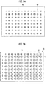
- Fig. 7A is a plan view of the RFID reader/writer 60.
- Fig. 7B is a plan view of the well plate 19 in which the PCR tubes 40 are disposed.
- the position (direction) of the RFID tag 48 of each PCR tube 40 is made to the same position (direction) as the RFID tags 48 of the other PCR tubes 40 disposed at the well plate 19 by the positioning part (not illustrated in Fig. 7 ).
- the RFID reader/writer 60 has a plurality of reader/writer antennas 62, and the reader/writer antennas 62 are provided at positions corresponding to positions of the well holders (PCR tubes 40) of the well plate 19.
- each reader/writer antenna 62 is disposed at the position of each well holder, preferably, on the RFID tag 48 of the PCR tube 40.
- the RFID tag of a PCR tube disposed at the next well holder may be read in a case where the RFID tag is read by the RFID reader/writer 60.
- a corresponding RFID tag can be reliably read by the RFID reader/writer by determining the position thereof by the positioning part.
- the information of the cell read by the RFID reader/writer 60 or the arrangement information on the well plate is collated with information of cells or arrangement information on a well plate managed by a computer 66, using a controller 64. Additionally, the information obtained by imaging the cell and the optical information from the cell are again written in the RFID tag 48. Accordingly, the information of the cell within the PCR tube 40 can be managed by the RFID tag 48.
- Fig. 8 is a plan view illustrating another aspect of the RFID reader/writer.
- an RFID reader/writer 360 illustrated in Fig. 8 one reader/writer antenna 362 is provided, and the information of the RFID tag 48 can be read by scanning the RFID reader/writer 360 with scanning means (not illustrated).
- scanning means not illustrated.
- Fig. 9 is a schematic view illustrating an RFID sample management system having display means.
- the display means 72 Fig. 9 illustrates an aspect in which an LED display unit 74 is provided at a position facing the bottom face of each PCR tube 40, on the bottom face side of the PCR tube 42.
- the next processing is performed on a cell within a PCR tube is determined in determination means (not illustrated).
- An LED display unit 74 corresponding to the PCR tube 40 including the cell determined to be subjected to the next processing is turned on by the controller 64. By turning on the LED display unit 74, the cell to be subjected to the next processing can be visually checked.
- the RFID reader/writer 60 is disposed above the PCR tube 40 and reads the information of the RFID tag 48. Hence, it is difficult to take out the PCR tube 40 having the cell to be subjected to the next processing while performing the reading with the RFID reader/writer 60. Additionally, in a case where the display means is provided on the RFID reader/writer side, a relevant PCR tube will not be clear anymore by moving the RFID reader/writer.
- the relevant PCR tube 40 can be checked even in a case where the RFID reader/writer 60 is moved.
- the RFID sample management method of the present embodiment includes at least a first writing step of writing information of a cell, arrangement information of a well plate, and the like in an RFID tag of a PCR tube; a step of fractionating the cell in the PCR tube; a step of imaging the fractionated cell and acquiring a cell image; a step of sorting a target cell on the basis of the cell image; a step of reading the information from the RFID tag of the PCR tube with an RFID reader/writer; and a second writing step of writing information of the target cell.
- information may be printed on a tube body.
- the printing of the information is performed by a code printing step of describing at least any one of a QR code or a data matrix code in the tube body; and a character printing step of describing at least any one of the information of the cell, or the arrangement information of the tube body on the well plate.
- a step of turning on display means corresponding to the tube body to which the target cell sorted by the sorting step is fractionated may be performed.
- the first writing step is a step of writing at least any one of the information of the cell fractionated to the RFID tag of the PCR tube or the arrangement information on the well plate in which the PCR tube is disposed.
- the writing of the information onto the RFID tag can be performed by the RFID reader/writer. Additionally, the same information as the information written in the RFID tag is input to a computer.
- the code printing step is a step of describing at least any one of the QR code or the data matrix code in the tube body.
- the QR code or the data matrix code in the tube body the information can be individually read by a code reader.
- the QR code and the data matrix code can be described by printing by an ink jet printer or marking by a laser marker.
- the character printing step is a step of describing at least any one of the information of the cell or the arrangement information of the tube body on the well plate in the tube body.
- the character printing can be performed together with the code printing, or can be performed by the ink jet printer or the laser marker.
- the step of fractionating the cells can be performed by, for example, flow cytometry. Additionally, a plurality of cells can be collectively added dropwise onto a well plate in which PCR tubes and the well plate are integral with each other, and can be fractionated to the PCR tubes in a centrifugal manner or stationary manner.
- the step of acquiring the cell image can be performed using the analysis device illustrated in Fig. 4 .
- the acquisition of the cell image can be performed by acquisition of an light transmission image of the cell by visible light, using a bright view field light source device, acquisition of fluorescent emission light from a fluorescent dye labeled on the cell by an antigen-antibody reaction or the like.
- the target cell is sorted on the basis of the cell image obtained by the step of acquiring the cell image.
- the sorting of the target cell can be performed depending on the shape of the cell, or the shape of a nucleus in the case of a nucleus cell. Additionally, the target cell can be sorted depending on the intensity of the fluorescent emission light.
- the information is read from the RFID tag of the PCR tube.
- the reading of the information from the RFID tag is performed using the RFID reader/writer disposed above the RFID tube.
- the information managed by computer and the information managed by the RFID tag are associated with each other.
- the second writing step is a step of writing the information of the target cell in the RFID tag of the PCR tube.
- the writing of the information onto the RFID tag can be performed by the RFID reader/writer. Additionally, as the information of the cell, it is preferable to write conditions in the step of fractionating the cell, for example, conditions of the flow cytometry, conditions in the step of sorting the target cell, or the like.
- the step of turning on the display means is a step of turning on display means corresponding to the tube body to which the target cell sorted in the sorting step is fractionated.
- the information can be managed with the RFID tag.
- sample management can be reliably performed.
Landscapes
- Chemical & Material Sciences (AREA)
- Health & Medical Sciences (AREA)
- Engineering & Computer Science (AREA)
- Life Sciences & Earth Sciences (AREA)
- Physics & Mathematics (AREA)
- General Physics & Mathematics (AREA)
- General Health & Medical Sciences (AREA)
- Analytical Chemistry (AREA)
- Biochemistry (AREA)
- Bioinformatics & Cheminformatics (AREA)
- Chemical Kinetics & Catalysis (AREA)
- Immunology (AREA)
- Pathology (AREA)
- Wood Science & Technology (AREA)
- Zoology (AREA)
- Biotechnology (AREA)
- Organic Chemistry (AREA)
- Theoretical Computer Science (AREA)
- Computer Hardware Design (AREA)
- Microelectronics & Electronic Packaging (AREA)
- Clinical Laboratory Science (AREA)
- Toxicology (AREA)
- Microbiology (AREA)
- Biomedical Technology (AREA)
- Genetics & Genomics (AREA)
- Medicinal Chemistry (AREA)
- Sustainable Development (AREA)
- General Engineering & Computer Science (AREA)
- Computer Networks & Wireless Communication (AREA)
- Electromagnetism (AREA)
- Artificial Intelligence (AREA)
- Computer Vision & Pattern Recognition (AREA)
- Automatic Analysis And Handling Materials Therefor (AREA)
- Apparatus Associated With Microorganisms And Enzymes (AREA)
Description
- The present invention relates to a PCR tube, an RFID sample management system, and an RFID sample management method, and particularly, to a PCR tube having an RFID, and an RFID sample management system and an RFID sample management method using this PCR tube.
- As methods of acquiring a target cell from a plurality of cells, for example, fractionating the target cell is performed by flow cytometry. The flow cytometry is a method of dispersing cells in a fluid, allowing the fluid to flow finely, optically analyzing the cells, and performing determination and preparative isolation of a cell to be acquired on the basis of this analysis result. The fractionated cell is then analyzed. For example, in a prenatal test, the percentage of target cells during preparative isolation using the flow cytometry is about 70 percent to about 80 percent. For that reason, it is inefficient to perform analysis or pretreatment for analysis to all cells fractionated by the flow cytometry. For example, in a case where a tube is moved in order to take out the tube to be analyzed or processing and analysis are simultaneously performed in order to efficiently analyze a plurality of samples, sample management is essential so that samples are not confused.
- As a method of managing samples, a method using a radio frequency identification (RFID) tag is performed. In this method, by disposing a member having an attachable and detachable RFID tag under the tube, information management of a cell within a polymerase chain reaction (PCR) tube is performed. Additionally, in the following
JP2002-082120A - In the prenatal diagnosis, containers for analyzing cells need only to be capable of containing one cell and are small containers. Therefore, it is difficult to describe a lot of information in each container. Additionally, in a case where the RFID tag is installed, the size of the related-art containers is large. Additionally, in the PCR tube or the like, in a case where the PCR processing is performed, a temperature is applied. Therefore, a place where the RFID tag is installed is limited.
- The invention has been made in view of such circumstances, and an object thereof is to provide a PCR tube that can reliably perform sample management within the PCR tube, an RFID sample management system, and an RFID sample management method.
- In order to achieve the above object, a PCR tube related to the invention comprises a tube body that has an opening at one end and has a collar part around the opening; and a lid part that is attachably and detachably mounted on the tube body and seals the opening of the tube body at the time of mounting. An RFID tag having a passive antenna built therein is provided at the collar part or the lid part. The antenna has directivity in a direction opposite to a bottom face of the tube body.
- According to the PCR tube of the invention, the RFID tag is provided at the collar part of the tube body, or the lid part. Accordingly, even in a case where PCR processing is performed using the PCR tube, a temperature can be prevented from being applied to the RFID tag, and management of the information stored in the RFID tag can be reliably performed. Additionally, by making the antenna of the RFID tag have the directivity in the direction opposite to the bottom face of the tube body, the reader/writer is installed on side opposite to the bottom face of the tube body in a case where the information of the RFID tag is read by the reader/writer. Accordingly, a distance from the RFID tag can be shortened and the information of the RFID tag can be read. Hence, even in a case where the antenna is short and the range of the directivity is narrow, the reading can be made by the reader/writer. Thus, the RFID tag can be made small and the installation of the RFID tag to the collar part or the lid part is possible.
- In addition, "the bottom face of the tube body" indicates a face that is in contact with the cell in a case where cell observation and the PCR processing are performed within the PCR tube.
- In one aspect of the PCR tube related to the invention, it is preferable that the PCR tube further comprises a positioning part that determines a position of the RFID tag in a case where the tube body is disposed on a well plate.
- According to this aspect, the positioning part in a case where the tube body is disposed in the well plate is provided. Accordingly, the positions of the RFID tags of a plurality of the PCR tubes disposed in the well plate can be the same position. Hence, the information can be reliably read without erroneously reading the RFID tag of the next PCR tube in a case where the reading is made by the reader/writer.
- In one aspect of the PCR tube related to the invention, it is preferable that the positioning part is a notch part provided in the collar part.
- According to this aspect, the notch part provided in the collar part is used as the positioning part. For example, alignment of the PCR tube can be easily performed by providing a protrusion on the well plate and combining the protrusion with the notch part.
- In one aspect of the PCR tube related to the invention, it is preferable that the RFID tag provided at the lid part is attachable and detachable.
- According to this aspect, the RFID tag provided at the lid part is made attachable and detachable. Accordingly, the RFID tag can be reused and costs can be reduced.
- In one aspect of the PCR tube related to the invention, it is preferable that the RFID tag is disposed within a structural body made of a light-transmissive material, and the lid part has a recess to which the structural body is attachable in a fitting manner.
- According to this aspect, the recess into which the structural body having the RFID tag at the lid part can be fitted is provided. Accordingly, exchange of the structural body can be easily performed. Additionally, by forming the structural body from the light-transmissive material, the sample within the PCR tube can be imaged.
- In one aspect of the PCR tube related to the invention, it is preferable that the light-transmissive material is a material selected from polypropylene, polystyrene, and acrylic resin.
- This aspect describes specific examples of the light-transmissive material, and the sample within the PCR tube can be imaged by using the above materials.
- In one aspect of the PCR tube related to the invention, it is preferable that a code configured in one dimension or two dimensions is described in the tube body.
- According to this aspect, the code configured in one dimension or two dimensions is described in the tube body. Accordingly, the information can be individually read by a code reader. Additionally, in a case where the information cannot be read due to a failure of the RFID tag, the information is read from the code configured in one dimension or two dimensions. Accordingly, the sample can be managed.
- In one aspect of the PCR tube related to the invention, it is preferable that at least any one of information of the cell or arrangement information of the tube body on the well plate is described in the tube body.
- According to this aspect, the information of the cell or the arrangement information of the tube body on the well plate is described. Accordingly, the sample within the PCR tube can be visually checked, without performing the reading with a reader.
- In order to achieve the above object, an RFID sample management system of the invention comprises the PCR tube described above; a well plate having a well holder in which the PCR tube is disposed; and an RFID reader/writer that has a reader/writer antenna and is capable of being disposed on a side opposite to the bottom face of the tube body.
- According to the RFID sample management system of the invention, the PCR tube described above is used. Accordingly, the directivity of the antenna of the RFID tag provided in the PCR tube is the side opposite to the bottom face of the tube body. By making it possible to dispose the RFID reader/writer on the side opposite to the bottom face of the tube body, the information of the sample within the PCR tube can be reliably read from the RFID tag, and the sample can be managed by the RFID tag.
- In one aspect of the RFID sample management system related to the invention, it is preferable that a plurality of the reader/writer antennas are provided and the plurality of reader/writer antennas are disposed at positions corresponding to the well holders of the well plate.
- According to this aspect, the reader/writer antennas provided in the reader/writer are respectively disposed at the positions corresponding to the well holders of the well plate. Accordingly, the information of the plurality of RFID tags can be read at a time.
- In one aspect of the RFID sample management system related to the invention, it is preferable that the system further comprises scanning means for scanning the RFID reader/writer.
- According to this aspect, the scanning means for scanning the RFID reader/writer is provided to scan the RFID reader/writer. Accordingly, the information of the RFID tags of the plurality of PCR tubes can be read. Additionally, in a case where the read information is made by the RFID reader/writer, the read information is information of a PCR tube under the RFID reader/writer. Therefore, the read information and the sample within the PCR tube can be reliably made to correspond to each other and can be prevented from being erroneously recognized.
- In one aspect of the RFID sample management system related to the invention, it is preferable that the system further comprises determination means for determining whether or not next processing of a cell within the tube body is to be performed; and display means for displaying the cell determined to be subjected to the next processing by the determination means.
- According to this aspect, the display means for displaying a cell determined to be subjected to processing next to the cell within the tube body is provided. Accordingly, even in a case where the RFID reader/writer is moved from a state where the RFID tag is read, a PCR tube containing a cell on which the next processing is performed can be checked.
- In one aspect of the RFID sample management system related to the invention, it is preferable that the display means is provided on the bottom face side of the tube body.
- According to this aspect, the display means is provided on the bottom face side of the tube body. Accordingly, the PCR tube having the cell on which processing is performed can be visually and easily checked. The PCR reader/writer is disposed on the side opposite to the bottom face of the tube body in a case where the information is read from the RFID tag. Hence, in a case where the PCR tube is taken out from the well plate, the PCR reader/writer should be moved. By providing the display means on the bottom face side of the tube body, even in a case where the RFID reader/writer is moved, a cell on which processing is performed can be visually checked by performing display with the display means.
- In order to achieve the above object, an RFID sample management method related to the invention comprises a first writing step of writing at least any one of information of a cell to be fractionated or arrangement information of a tube body disposed on a well plate, in the RFID tag of the PCR tube described above; a step of fractionating the cell in the PCR tube disposed on the well plate; a step of imaging the fractionated cell and acquiring a cell image; a step of sorting a target cell on the basis of the cell image; a step of reading the information from the RFID tag of the PCR tube with an RFID reader/writer disposed on a side opposite the bottom face of the tube body; and a second writing step of writing information of the target cell in the RFID tag of the PCR tube.
- According to the RFID sample management method of the invention, the RFID tag is disposed at the collar part of the tube body, or the lid part, by using the PCR tube described above. Therefore, even in a case where the PCR processing is performed, the information can be managed without breaking the recording of the RFID tag. Additionally, in a case where the information is read from the RFID tag by the RFID reader/writer or also in a case where the information is written in the RFID tag, the RFID reader/writer is disposed on the side opposite to the bottom face of the tube body of the PCR tube, the distance between the RFID tag and the RFID reader/writer can be shortened, and the size of the RFID tag can be made small. In this way, according to the RFID sample management method of the invention, the RFID tag is made small even in a case where the RFID tag is used for the PCR tube. Accordingly, the RFID tag can be installed at the position where a temperature is not applied by the PCR processing. Thus, the RFID tag can be can installed in the PCR tube, and from the step of fractionating the cell, in the step of imaging the fractionated cell and the step of sorting the target cell, and also in the subsequent processing, the cell (sample) can be managed by the RFID tag.
- In one aspect of the RFID sample management method related to the invention, it is preferable that the method further comprises a code printing step of describing a code configured in one dimension or two dimensions in the tube body before the step of fractionating the cell.
- According to this aspect, the code configured in one dimension or two dimensions is described in the tube body. Accordingly, the information can be individually read by a code reader. Additionally, in a case where the information cannot be read due to a failure of the RFID tag, the information is read from the code configured in one dimension or two dimensions. Accordingly, the sample can be managed.
- Here, as preferable one-dimensional codes, for example, CODE 39, NW7, and CODE 128 can be used, and as preferable two-dimensional codes, for example, a quick response (QR) code (Registered Trademark), DataMatrixCode, VeriCode, an RFD417 code, and a CODE49 code can be used. Moreover, it is more preferable to use DataMatrixCode.
- In one aspect of the RFID sample management method related to the invention, it is preferable that the method further comprises a character printing step of describing at least any one of the information of the cell or the arrangement information of the tube body on the well plate, in the tube body, before the step of fractionating the cell.
- According to this aspect, the information of the cell or the arrangement information of the tube body on the well plate is described. Accordingly, the sample within the PCR tube can be visually checked, without performing the reading with a reader.
- In one aspect of the RFID sample management method related to the invention, it is preferable that a display means is provided at a position that faces each tube body, and the method further comprises a step of turning on the display means corresponding to the tube body to which the target cell sorted in the sorting step is fractionated.
- According to this aspect, the display means corresponding to the tube body to which the target cell sorted in the sorting step is fractionated is turned on. Accordingly, after the PCR reader/writer is moved, the PCR tube including the target cell can be can be visually checked. Hence, the PCR tube having the cell to be processed can be taken out from the well plate without erroneous reading.
- According to the PCR tube of the invention, the RFID tag in which the passive antenna having the directivity in the direction opposite to the bottom face of the tube body, that is, upward directivity, is built is provided at the collar part of the PCR tube, or the lid part. Accordingly, reading can be made from above the PCR tube by the reader/writer. By disposing the RFID tag the collar part of the PCR tube, or the lid part, a temperature can be effectively applied to the PCR tube in the case of the PCR processing. Additionally, by performing reading from above the RFID tag with the reader/writer, the distance between the RFID tag and the reader/writer can be shortened. Thus, the RFID tag can be made small. Hence, also in a small-sized PCR tube, information management can be reliably performed using the RFID tag.
- Additionally, according to the RFID sample management system and the RFID sample management method of the invention, the information is recorded on the RFID tag. Accordingly, even in the subsequent step, a sample within a PCR tube can be managed.
-
-
Fig. 1 is a cross-sectional view illustrating the shape of a PCR tube. -
Fig. 2 is a plan view of the PCR tube. -
Fig. 3 is a plan view illustrating a modification example of the PCR tube. -
Fig. 4 is a schematic configuration view illustrating the configuration of an analysis device that captures an image of a cell. -
Fig. 5 is a cross-sectional view illustrating the shape of another embodiment of the PCR tube. -
Fig. 6 is a schematic view illustrating an RFID sample management system. -
Fig. 7A is a plan view of an RFID reader/writer. -
Fig. 7B is a plan view of a well plate in which PCR tubes are disposed. -
Fig. 8 is a plan view of the well plate in which the PCR tubes are disposed and an RFID reader/writer of another embodiment. -
Fig. 9 is a schematic view illustrating another embodiment of the RFID sample management system. - Hereinafter, a PCR tube related to the invention, and an RFID sample management system and an RFID sample management method using this PCR tube will be described with reference to the accompanying drawings. In addition, in the present specification, "to" is used in the meaning including numerical values described before and after "to" as lower limits and upper limits.
-
Fig. 1 is a cross-sectional view illustrating an example of the shape of aPCR tube 40 used in the present embodiment, andFig. 2 is a plan view of thePCR tube 40. ThePCR tube 40 illustrated inFig. 1 is a PCR tube that can be used for imaging of a cell fractionated in thePCR tube 40, using ananalysis device 10 illustrated inFig. 4 to be described below and also for a device that acquires optical information from the cell. - The
PCR tube 40 includes atube body 42, and alid part 44 on which thetube body 42 is attachably and detachably mounted. Thetube body 42 has an opening at one end, and has acollar part 46 around this opening. Additionally, thelid part 44 seals the opening of thetube body 42 in a case where thetube body 42 is mounted. AnRFID tag 48 is disposed in thecollar part 46, and a sample (cell) within thePCR tube 40 is managed by theRFID tag 48. In addition, the collar part can also be referred to as a flange part. - It is preferable that information of the cell within the
PCR tube 40, positional information of a well plate, and the like are stored in theRFID tag 48. By storing the information of the cell and the positional information of the well plate, information can be managed also in a case where thePCR tube 40 is moved from thewell plate 19. - The
RFID tag 48 is constituted of an IC chip and an antenna. In the present embodiment, the antenna built in theRFID tag 48 is a passive antenna, and has directivity in a direction opposite to abottom face 42a of thetube body 42, that is, upward directivity inFig 1 . By making the directivity of the antenna built in theRFID tag 48 upward, an RFID reader/writer disposed in a case where information is written in the RFID tag or information is read can be disposed close to an upper side of thePCR tube 40. Since the antenna built in the RFID tag can be downsized by disposing theRFID tag 48 and the RFID reader/writer close to each other, theRFID tag 48 itself can be downsized. - By downsizing the
RFID tag 48, theRFID tag 48 can be installed also in a small container like thePCR tube 40. Additionally, in thePCR tube 40, it is necessary to apply a temperature in order to PCR-process the cell within thePCR tube 40. Hence, in a case where the RFID tag is disposed on a side face or a bottom face of the tube body, there is a case where heat may be applied the PCR processing, the RFID tag may be broken, and information may not be readable. By downsizing theRFID tag 48, since theRFID tag 48 can be installed in thecollar part 46, theRFID tag 48 can reliably perform the management of the cell. TheRFID tag 48 can be installed in thecollar part 46 of thetube body 42 by an embedding method. The size of theRFID tag 48 can be a size of 1 mm x 1 mm x 0.15 mm (thickness). -
Fig. 3 is a plan view illustrating a modification example of aPCR tube 140 having theRFID tag 48 in the collar part. ThePCR tube 140 illustrated inFig. 3 has a positioning part that determines the position of theRFID tag 48 in a case where the tube body is disposed on the well plate. - As the positioning part, a
collar part 146 of the tube body and alid part 144 can be provided with anotch part 150. By disposing the PCR tube such that thenotch part 150 is fitted to a protrusion (not illustrated) provided on eachwell holder 18, the position of theRFID tag 48 of each PCR tube on thewell holder 18 can be the same position. As described above, in the present embodiment, the RFID reader/writer is brought close to the upper side of the PCR tube, so that the antenna of theRFID tag 48 can be downsized and theRFID tag 48 itself can be downsized. Hence, in a case where information is read from theRFID tag 48 by the RFID reader/writer, it is necessary to bright the RFID reader/writer close to theRFID tag 48. - In a case where the PCR tube is not provided with the positioning part, it is conceivable that an antenna part of the RFID reader/writer and an antenna part of the RFID tag are separated from each other by the distance of the outer shape of the PCR tube. In this case, in a case where the pitch of the
well holders 18 is short, there is a possibility that an RFID tag of a PCR tube next to the RFID tag of the above PCR tube to be originally read may be read. Accurate management of the sample cannot be performed in a case where the RFID tag of the next PCR tube is read. Hence, by making the position of the RFID tag in each PCR tube the same by the positioning part, the antenna of the RFID reader/writer can be disposed at an upper part of the antenna of the RFID tag of each PCR tube. Accordingly, the RFID reader/writer can be prevented from erroneously reading information of a different RFID tag. - Additionally, it is preferable that at least any one of a QR code or a data matrix code is described in a PCR tube body of the PCR tube. The RFID tag simultaneously reads a plurality of PCR tubes with the reader/writer, as will be described below. By describing the QR code and/or the data matrix code in the PCR tube body, the QR code and/or the data matrix code can be individually read, and information can be easily read.
- The QR code and/or the data matrix code can be described by printing by an ink jet printer or marking by a laser marker.
- Additionally, it is preferable that at least any one of the information of the cell or the arrangement information of the tube body on the well plate is described in the tube body. In order to read the information of the RFID tag, the reader/writer is required, and a code reader is also required in order to read the QR code or the data matrix.
- By describing the information of the cell or the arrangement information on the well plate in the tube body, without requiring reading the RFID tag, the QR code or the data matrix code, the information of the PCR tube and the cell within the PCR tube can be checked.
- As a method of describing the information of the cell or the arrangement information on the well plate in the tube body, the printing by the ink jet printer or the marking by the laser marker may be performed similarly to a case where the QR code and/or the data matrix code are described. Additionally, the information of the cell or the arrangement information may be described on a seal and pasted.
- Referring to
Fig. 1 , the shape of thetube body 42 will be described. The outer shape of thetube body 42 is a shape in which the tube body is capable of being loaded on a device that performs PCR processing, preferably, a PCR thermal cycler. By making the outer shape correspond to the device that performs the PCR processing, the PCR processing can be performed with the PCR tube, which has been captured an image, as it is. In a case where the tube body is capable of being loaded on the PCR thermal cycler, it is preferable that a gap between the device that performs the PCR processing and the outer shape of thetube body 42 is narrow. By making the gap between the device and thetube body 42 small, a temperature can be efficiently applied to thetube body 42. Additionally, in order to efficiently apply a temperature in a case where the PCR processing is performed, it is preferable that the outer shape and the inner shape of the tube body are substantially the same (analogue), and it is more preferable that the thickness of the side face is uniform from the bottom face to an opening part. By making the thickness uniform, heat is efficiently and uniformly transmitted to the cell within thetube body 42, and a culture solution. Accordingly, it is possible to accurately control the PCR processing. - In the
analysis device 10 illustrated inFig. 4 , excitation light is radiated from thebottom face 42a side of thetube body 42, and fluorescence emission occurs from the cell that has emitted light due to the excitation light transmitted through thetube body 42. In order to receive the fluorescence including the information of the cell, it is required that the material of thetube body 42 is a material that satisfies conditions, such as being transparent, not auto-fluorescing, not scattering the fluorescence, and withstanding a temperature cycle performed by the PCR. Additionally, in order to image thecell 16, it is preferable that thebottom face 42a inside thetube body 42 has a flat shape. By making thebottom face 42a of thetube body 42 flat, it is possible to adjust a focal point to thecell 16, and image analysis of thecell 16 that is present on thebottom face 42a can be accurately performed. - Additionally, it is preferable that side faces 42b and 42c of the
tube body 42 are formed in a direction that widens toward the opening part of the container from the bottom face. By making the opening part of thetube body 42 wide, and making the tube body narrow toward thebottom face 42a, thecell 16 can be easily introduced into thetube body 42 and can be easily guided to thebottom face 42a. - In
Fig. 1 , it is preferable that theside face 42b in contact with thebottom face 42a is formed such that an angle θB on a side face side, which is an angle formed between thebottom face 42a and theside face 42b, is 50° or more and 80° or less. Bubbles in the culture solution can be easily extracted by setting the angle θB formed between thebottom face 42a and theside face 42b to 80° or less. Additionally, by setting the angle θB formed between thebottom face 42a and theside face 42b to 50° or more, a space formed by thebottom face 42a and theside face 42b can be narrowed, and thecell 16 can be dipped in the culture solution with a smaller amount of culture solution. Additionally, the depth of the culture solution within thetube body 42 can be prevented from becomes shallow, and the culture solution and thecell 16 can be prevented from drying out. - As illustrated in
Fig. 1 , it is preferable that the side face of thetube body 42 are bent in multi-stages. In a case where the side face is bent in multi stages, it is preferable that theside face 42c other than theside face 42b in contact with thebottom face 42a is formed such that an angle θC on the side face side, which is an angle between eachside face 42c and a parallel line of thebottom face 42a is 40° or more and 90° or less. In a case where the angle is 40° or more, it is possible to reliably contain the cell on the bottom face without stagnating the cell at an inclination of theside face 42c. Additionally, as the angle is 40° or more, this is preferable because it is possible to narrow the opening of thetube body 42 and it is possible to contain thePCR tube 40 in the narrow space of thewell plate 19. Moreover, in a case where the side face is bent in multi stages, it is preferable that the angle θC becomes gradually smaller toward thebottom face 42a from the opening except for theside face 42b in contact with thebottom face 42a. By adopting such a configuration, it is possible to easily guide the cell fractionated in thetube body 42 to thebottom face 42a. - It is preferable that the angle θA, which is twice as large as the angle at which a line connecting the center (the center of a circle approximated to a circumscribed circular shape) of the
bottom face 42a, and an end part of the opening is formed with respect to a perpendicular straight line to the bottom face, is less than 45°. By setting the angle θA to less than 45 degrees, the opening of thetube body 42 can be prevented from widening, and it is possible to make the space of thewell plate 19 small. - Additionally, it is preferable that a thickness t of the
bottom face 42a of thetube body 42 is set to 0.2 mm or more and 1 mm or less. As illustrated inFig. 4 , an aspect in which thecell 16 is imaged from thebottom face 42a side of thetube body 42 is preferable. As long As the thickness of thebottom face 42a is less than 1 mm, alens 20 is allowed to approach thecell 16, which is preferable. Additionally, as long as the thickness is 0.2 mm or more, this is preferable because since a focal point of a scratch or adhering dust or dirt on the outside of thetube body 42 is out of the focal depth and an image to be captured is not affected, only an image of the cell can be captured. - As the material of the
tube body 42, in a case where an image is captured, it is preferable to use a material that easily transmits light. Specifically, a material selected from polypropylene, polystyrene, or acrylics can be used. Additionally, the PCR tube using these materials is also excellent in heat resistance, and can perform the PCR processing without degradation of the PCR tube even in a case where the PCR tube is applied to the PCR thermal cycler. In the PCR tube manufactured using these materials, the transmittance thereof with respect to light with a wavelength of 350 nm or more and 800 nm or less is preferably 60% or more, more preferably 70% or more, and still more preferably 80% or more. In addition, in the invention, the "transmittance" is a value (transmittance = transmitted light/incident ray x 100) obtained by dividing transmitted light by incident rays. For example, in a case where a beam transmitted in a case where a beam of 100 is made incident is 60, the transmittance is calculated to be 60%. Additionally, as illustrated inFig. 4 , the material of thelid part 44 is also preferably a material that easily transmits light, and is preferably the same material as thetube body 42 in order to radiate the light for measuring the transmitted light of the cell from thelid part 44 side. - In addition, in
Figs. 1 to 3 , although the PCR tube that can perform imaging and analysis of the cell fractionated in thePCR tube 40 has been described, the PCR tube of the invention is not limited to this. Cells may be fractionated in other containers and analyzed, a cell to be subjected to the PCR processing may be determined, and then, the cell may be moved to the PCR tube that has the RFID tag at the collar part and can perform the PCR processing. - Next, an analysis device to which the PCR tube of the present embodiment is applied and which includes an imaging device for capturing an image will be described. In addition, although a device that analyzes the cell fractionated in the PCR tube will be described as an example of the analysis device, the invention is not limited to this.
-
Fig. 4 is a schematic configuration view illustrating imaging of a target cell fractionated in the PCR tube, and the configuration of a device that acquires the optical information from the cell. As a preferable aspect, there is an analysis device that allows acquisition of fluorescent emission light from a fluorescent dye labeled on the fractionated cell by the antigen-antibody reaction or the like or acquisition of an light transmission image of the cell resulting from visible light. - The
analysis device 10 illustrated inFig. 4 includes a fluorescence excitationlight source device 12 for radiating light for measuring the fluorescence emitted from the target cell; a bright view field light source device 14 that radiates light (visible light) for measuring the transmitted light of the cell; thewell plate 19 havingPCR tubes 40 each containing thecell 16 serving as a target to be imaged and thewell holders 18; a filter group (filter cube) 28 holding thelens 20, anexcitation filter 22, adichroic mirror 24, and afluorescent filter 26; and animaging device 30 that images the fluorescence and the transmitted light from thecell 16. - As the fluorescence excitation
light source device 12, a high-pressure mercury lamp, a high-pressure xenon lamp, an LED (light emitting diode), a light amplification by stimulated emission of radiation (LASER), or the like can be used. By using these light sources to narrow a wavelength range of the radiation light to be radiated to thecell 16, it is possible to reliably perform high-accuracy analysis. Additionally, as the fluorescence excitationlight source device 12, a tungsten lamp, a halogen lamp, a white LED, or the like can be used. Even in a case where these light sources are used, thecell 16 can be irradiated with light with a target wavelength by allowing theexcitation filter 22 to transmit only the light with a target wavelength. In addition, the same light source as the bright view field light source device 14 can also be used as the fluorescence excitationlight source device 12. - The
well plate 19 holds thewell holders 18, and thePCR tubes 40 of the present embodiment, and holds thecell 16 serving as an observation target. Thecell 16 is supplied to eachPCR tube 40 together with a cell culture solution. - The
lens 20 magnifies the fluorescence emitted by thecell 16 due to the light output from the fluorescence excitationlight source device 12, and the transmitted light obtained by the light output from the bright view field light source device 14 is transmitted through thecell 16. A lens used for optical measurement can be used for thelens 20. - The
filter group 28 includes theexcitation filter 22, thedichroic mirror 24, and thefluorescent filter 26. As a specific example of such afilter group 28, it is preferable to use a filter cube. For example, Zeiss Filter Set49 (DAPI: 4',6-diamidino-2-phenylindole) can be used. The light radiated from the fluorescence excitationlight source device 12 is made to be only the light of the target wavelength range by theexcitation filter 22. The light that has transmitted theexcitation filter 22 is reflected toward thewell plate 19 by thedichroic mirror 24. The fluorescent emission light from thecell 16, which is generated by the excitation light emitted from the fluorescence excitationlight source device 12, is captured by theimaging device 30 through thelens 20, thedichroic mirror 24, and thefluorescent filter 26. Since the fluorescence emitted by the excitation light has a wavelength range on a longer wavelength side than the excitation light, it is possible to use thedichroic mirror 24, thereby allowing only the fluorescent emission light to be transmitted therethrough. Moreover, by using thefluorescent filter 26 that allows only the fluorescence to be transmitted therethrough, without transmitting the excitation light, it is possible to perform imaging with information of only the fluorescent emission light from thecell 16 by theimaging device 30. Therefore, the image captured by theimaging device 30 is not affected by the excitation light, and the accuracy of testing by the fluorescent emission light information can be improved. - In the fluorescence imaging caused by the light radiated from the fluorescence excitation
light source device 12, immunostaining is normally performed using a plurality of kinds of coloring agents in order to acquire a plurality of pieces of information for one cell in accordance with the test purpose of the cell. In this case, optical information with different wavelengths can be independently acquired by imaging the fluorescence generated from the plurality of kinds of coloring agents of the immunostained cell, using a filter group having transmission characteristics or reflective characteristics suitable for the fluorescence wavelengths of the respective coloring agents. In addition, in a case where the transmitted light of thecell 16 is imaged by the bright view field light source device 14, the imaging is performed in a state where thefilter group 28 is detached. Accordingly, the transmitted light can be imaged by theimaging device 30. - The
imaging device 30 is not particularly limited as long as to the fluorescence or the transmitted light of thecell 16 fractionated in thePCR tube 40 on thewell plate 19 can be imaged. For example, a charge-coupled device (CCD) camera can be used. - As a method of fractionating the cell in the PCR tube, for example, flow cytometry can be performed. Additionally, a plurality of cells can be collectively added dropwise onto a well plate in which PCR tubes and the well plate are integral with each other, and can be fractionated in the PCR tubes in a centrifugal manner (100 rpm·1 minute) or stationary manner. In a case where the PCR tubes and the well plate are formed integrally with each other, it is preferable to provide a cutting introduction mechanism for grooves, cutting lines, printing lines, or the like in a plate. By cutting the plate with this cutting introduction mechanism, it is possible to individually process the PCR tubes.
-
Fig. 5 is a cross-sectional view illustrating the shape of another embodiment of the PCR tube. ThePCR tube 240 illustrated inFig. 5 is different from the PCR tube illustrated inFig. 1 in that anRFID tag 248 is disposed at alid part 244. By providing thelid part 244 with theRFID tag 248 and making the directivity of an antenna upward, information of theRFID tag 248 can be read by the RFID reader/writer. Additionally, also in thePCR tube 240, the antenna built in theRFID tag 248 can be downsized. Thus, theRFID tag 248 itself can be downsized. Additionally, by providing thelid part 244 with theRFID tag 248, it is possible to prevent a situation in which, due to heating in the PCR processing, the RFID tag breaks and information cannot be read. In addition, since thetube body 42 has the same configuration as the tube body illustrated inFig. 1 except that the RFID tag is not provided at the collar part, the description thereof will be omitted. - It is preferable that the
RFID tag 248 provided in thelid part 244, is attachably and detachably provided in thelid part 244. By making theRFID tag 248 attachable and detachable, theRFID tag 248 can be reused. - In a case where the
RFID tag 248 is attachably and detachably disposed, arecess 252 is formed in thelid part 244, astructural body 254 that is attachable in a fitting manner is formed in therecess 252. In a case where thestructural body 254 is fitted into therecess 252 of thelid part 244, it is preferable that theRFID tag 248 is disposed within thestructural body 254 such that theRFID tag 248 is disposed on an opening side of therecess 252. By providing theRFID tag 248 within thestructural body 254 so as to be located on the upper side of thelid part 244, it is possible to perform reading from above thePCR tube 240 with the reader/writer. - It is preferable that a light-transmissive material is used as a material that constitutes the
lid part 244 and thestructural body 254. In a case where the analysis device illustrated inFig. 4 is used and in a case where the transmitted light of thecell 16 is measured, light is radiated by the bright view field light source device 14 from thelid part 244 side of thePCR tube 240. Hence, it is preferable that thelid part 244 and thestructural body 254 are formed of the light-transmissive material. In addition, in a case where the cell fractionated in the PCR tube is imaged and in a case where it is not determined whether or not the PCR processing is to be performed, the material of the lid part and the structural body is not particularly limited. - In addition, although the RFID tag does not have light transmittance, the size thereof is small, the imaging can be made with the scattered light or the like from the bright view field light source device 14. Therefore, there is no particular problem.
- Polypropylene, polystyrene, and acrylic resin can be used as the light-transmissive material. As illustrated in
Fig. 5 , theRFID tag 248 can be disposed by forming the recess in thestructural body 254 made of light-transmissive resin and embedding the RFID tag in the recess with an adhesive. - In a case where the
RFID tag 248 is provided in thelid part 244, it is preferable that theRFID tag 248 is provided at the center of thelid part 244. By providing the RFID tag at the center of theiid part 244, even in a case where alignment at the time of being disposed in thewell holder 18 is not performed, the position of theRFID tag 248 and the position of the antenna of the RFID reader/writer can be prevented from deviating. However, even in a case where theRFID tag 248 is not provided at the central part of thelid part 244, the distance between the RFID tag and the antenna of the RFID reader/writer is shorter than that in a case where the RFID tag is provided at the collar part. Thus, the RFID tag can be prevented from being erroneously read. -
Fig. 6 is a schematic view illustrating an RFID sample management system using the above-described PCR tube. InFig. 6 , although thePCR tube 40 having theRFID tag 48 at the collar part of thetube body 42 has been described, a PCR tube having the RFID tag at the lid part can also be similarly used. - The RFID sample management system includes
PCR tubes 40, thewell plate 19 having wellholders 18 in which thePCR tubes 40 are disposed, and an RFID reader/writer 60 that is capable of being disposed on the lid side of the PCR tubes and has a reader/writer antenna 62. The RFID reader/writer 60 is disposed on the side opposite to the bottom face of thetube body 42, that is, the upper side of thePCR tube 40. In addition, inFig. 6 , although a state where the RFID reader/writer 60 is disposed on thePCR tubes 40 is illustrated, the RFID reader/writer is normally on standby at another location and is disposed in a case where the information of the RFID tags 48 of thePCR tubes 40 is read. -
Fig. 7A is a plan view of the RFID reader/writer 60.Fig. 7B is a plan view of thewell plate 19 in which thePCR tubes 40 are disposed. In thewell plate 19 illustrated inFig. 7B , the position (direction) of theRFID tag 48 of eachPCR tube 40 is made to the same position (direction) as the RFID tags 48 of theother PCR tubes 40 disposed at thewell plate 19 by the positioning part (not illustrated inFig. 7 ). The RFID reader/writer 60 has a plurality of reader/writer antennas 62, and the reader/writer antennas 62 are provided at positions corresponding to positions of the well holders (PCR tubes 40) of thewell plate 19. As described above, in theRFID tag 48 provided in eachPCR tube 40, theRFID tag 48 itself is made small by downsizing its antenna. Thus, the directivity of the antenna is narrow. Hence, the position of each reader/writer antenna 62 is disposed at the position of each well holder, preferably, on theRFID tag 48 of thePCR tube 40. - In a case where positioning the
PCR tube 40 is not performed, for example, in a case where the outer shape of the opening of thetube body 42 is 6 mm, the pitch (a shortest distance from one end of a well holder to one end of the adjacent well holder) of the well holders is 9 mm, the RFID tag of a PCR tube disposed at the next well holder may be read in a case where the RFID tag is read by the RFID reader/writer 60. Hence, a corresponding RFID tag can be reliably read by the RFID reader/writer by determining the position thereof by the positioning part. - The information of the cell read by the RFID reader/
writer 60 or the arrangement information on the well plate is collated with information of cells or arrangement information on a well plate managed by acomputer 66, using acontroller 64. Additionally, the information obtained by imaging the cell and the optical information from the cell are again written in theRFID tag 48. Accordingly, the information of the cell within thePCR tube 40 can be managed by theRFID tag 48. -
Fig. 8 is a plan view illustrating another aspect of the RFID reader/writer. In an RFID reader/writer 360 illustrated inFig. 8 , one reader/writer antenna 362 is provided, and the information of theRFID tag 48 can be read by scanning the RFID reader/writer 360 with scanning means (not illustrated). In this case, it is not necessary to strictly position eachPCR tube 40 strictly as in the case of using the RFID reader/writer illustrated inFig. 7A . This is because there is no erroneous reading of the RFID tag of the next PCR tube as long as the position can be ascertained. -
Fig. 9 is a schematic view illustrating an RFID sample management system having display means. As the display means 72,Fig. 9 illustrates an aspect in which anLED display unit 74 is provided at a position facing the bottom face of eachPCR tube 40, on the bottom face side of thePCR tube 42. - On the basis of the observation of the cell by the imaging or the optical information of the cell, whether or not the next processing is performed on a cell within a PCR tube is determined in determination means (not illustrated). An
LED display unit 74 corresponding to thePCR tube 40 including the cell determined to be subjected to the next processing is turned on by thecontroller 64. By turning on theLED display unit 74, the cell to be subjected to the next processing can be visually checked. According to thePCR tube 40 of the present embodiment, the RFID reader/writer 60 is disposed above thePCR tube 40 and reads the information of theRFID tag 48. Hence, it is difficult to take out thePCR tube 40 having the cell to be subjected to the next processing while performing the reading with the RFID reader/writer 60. Additionally, in a case where the display means is provided on the RFID reader/writer side, a relevant PCR tube will not be clear anymore by moving the RFID reader/writer. - As illustrated in
Fig. 9 , by providing theLED display unit 74 on the bottom face side of thePCR tube 40 and turning on theLED display unit 74 at the position corresponding to thePCR tube 40 having the cell that proceeds to the next processing, therelevant PCR tube 40 can be checked even in a case where the RFID reader/writer 60 is moved. - Next, an RFID sample management method using the PCR tube and the RFID sample management system of the present embodiment will be described. The RFID sample management method of the present embodiment includes at least a first writing step of writing information of a cell, arrangement information of a well plate, and the like in an RFID tag of a PCR tube; a step of fractionating the cell in the PCR tube; a step of imaging the fractionated cell and acquiring a cell image; a step of sorting a target cell on the basis of the cell image; a step of reading the information from the RFID tag of the PCR tube with an RFID reader/writer; and a second writing step of writing information of the target cell.
- Additionally, prior to the step of fractionating the cell, information may be printed on a tube body. The printing of the information is performed by a code printing step of describing at least any one of a QR code or a data matrix code in the tube body; and a character printing step of describing at least any one of the information of the cell, or the arrangement information of the tube body on the well plate. Additionally, a step of turning on display means corresponding to the tube body to which the target cell sorted by the sorting step is fractionated may be performed.
- The first writing step is a step of writing at least any one of the information of the cell fractionated to the RFID tag of the PCR tube or the arrangement information on the well plate in which the PCR tube is disposed. The writing of the information onto the RFID tag can be performed by the RFID reader/writer. Additionally, the same information as the information written in the RFID tag is input to a computer.
- Additionally, the code printing step is a step of describing at least any one of the QR code or the data matrix code in the tube body. By describing the QR code or the data matrix code in the tube body, the information can be individually read by a code reader. The QR code and the data matrix code can be described by printing by an ink jet printer or marking by a laser marker.
- Additionally, the character printing step is a step of describing at least any one of the information of the cell or the arrangement information of the tube body on the well plate in the tube body. By describing the information of the cell or the arrangement information on the well plate in the tube body, the information of the cell within the PCR tube and can be visually checked. The character printing can be performed together with the code printing, or can be performed by the ink jet printer or the laser marker.
- Additionally, the step of fractionating the cells can be performed by, for example, flow cytometry. Additionally, a plurality of cells can be collectively added dropwise onto a well plate in which PCR tubes and the well plate are integral with each other, and can be fractionated to the PCR tubes in a centrifugal manner or stationary manner.
- The step of acquiring the cell image can be performed using the analysis device illustrated in
Fig. 4 . The acquisition of the cell image can be performed by acquisition of an light transmission image of the cell by visible light, using a bright view field light source device, acquisition of fluorescent emission light from a fluorescent dye labeled on the cell by an antigen-antibody reaction or the like. - In the step of sorting the target cell, the target cell is sorted on the basis of the cell image obtained by the step of acquiring the cell image. The sorting of the target cell can be performed depending on the shape of the cell, or the shape of a nucleus in the case of a nucleus cell. Additionally, the target cell can be sorted depending on the intensity of the fluorescent emission light.
- In the step of reading the information, the information is read from the RFID tag of the PCR tube. The reading of the information from the RFID tag is performed using the RFID reader/writer disposed above the RFID tube. By collating the information from the RFID tag with the information managed by the computer (sample management system), the information managed by computer and the information managed by the RFID tag are associated with each other.
- The second writing step is a step of writing the information of the target cell in the RFID tag of the PCR tube. The writing of the information onto the RFID tag can be performed by the RFID reader/writer. Additionally, as the information of the cell, it is preferable to write conditions in the step of fractionating the cell, for example, conditions of the flow cytometry, conditions in the step of sorting the target cell, or the like.
- The step of turning on the display means is a step of turning on display means corresponding to the tube body to which the target cell sorted in the sorting step is fractionated. By turning on the display means corresponding to the tube body to which the target cell is fractionated, the PCR tube to which the target cell is fractionated can be visually checked.
- In this way, according to the RFID sample management method of the present embodiment, the information can be managed with the RFID tag. Thus, sample management can be reliably performed.
-
- 10: analysis device
- 12: fluorescence excitation light source device
- 14: bright view field light source device
- 16: cell
- 18: well holder
- 19: well plate
- 20: lens
- 22: excitation filter
- 24: dichroic mirror
- 26: fluorescent filter
- 28: filter group (filter cube)
- 30: imaging device
- 40, 140, 240: PCR tube
- 42: tube body
- 42a: bottom face
- 42b, 42c: side face
- 44, 144, 244: lid part
- 46, 146: collar part
- 48, 248: RFID tag
- 60, 360: RFID reader/writer
- 62, 362: reader/writer antenna
- 64: controller
- 66: computer
- 72: display means
- 74: LED display unit
- 150: notch part
- 252: recess
- 254: structural body
Claims (17)
- A PCR tube comprising:a tube body that has an opening at one end and has a collar part around the opening; anda lid part that is attachably and detachably mounted on the tube body and seals the opening of the tube body at the time of mounting,wherein an RFID tag having a passive antenna built therein is provided at the collar part or the lid part, andwherein the antenna has directivity in a direction opposite to a bottom face of the tube body.
- The PCR tube according to claim 1, further comprising:
a positioning part that determines a position of the RFID tag in a case where the tube body is disposed on a well plate. - The PCR tube according to claim 2,
wherein the positioning part is a notch part provided in the collar part. - The PCR tube according to any one of claims 1 to 3,
wherein the RFID tag provided at the lid part is attachable and detachable. - The PCR tube according to claim 4,wherein the RFID tag is disposed within a structural body made of a light-transmissive material, andwherein the lid part has a recess to which the structural body is attachable in a fitting manner.
- The PCR tube according to claim 5,
wherein the light-transmissive material is a material selected from polypropylene, polystyrene, and acrylic resin. - The PCR tube according to any one of claims 1 to 6,
wherein a code configured in one dimension or two dimensions is described in the tube body. - The PCR tube according to any one of claims 1 to 7,
wherein at least any one of information of a cell or arrangement information of the tube body on the well plate is described in the tube body. - An RFID sample management system comprising:the PCR tube according to any one of claims 1 to 8;a well plate having a well holder in which the PCR tube is disposed; andan RFID reader/writer that has a reader/writer antenna and is capable of being disposed on a side opposite to the bottom face of the tube body.
- The RFID sample management system according to claim 9,
wherein a plurality of the reader/writer antennas are provided, and the plurality of reader/writer antennas are disposed at positions corresponding to the well holders of the well plate. - The RFID sample management system according to claim 9, further comprising:
scanning means for scanning the RFID reader/writer. - The RFID sample management system according to any one of claims 9 to 11, further comprising:determination means for determining whether or not next processing of the cell within the tube body is to be performed; anddisplay means for displaying the cell determined to be subjected to the next processing by the determination means.
- The RFID sample management system according to claim 12,
wherein the display means is provided on the bottom face side of the tube body. - An RFID sample management method comprising:a first writing step of writing at least any one of information of a cell to be fractionated or arrangement information of a tube body disposed on a well plate, in the RFID tag of the PCR tube according to any one of claims 1 to 8;a step of fractionating the cell in the PCR tube disposed on the well plate;a step of imaging the fractionated cell and acquiring a cell image;a step of sorting a target cell on the basis of the cell image;a step of reading the information from the RFID tag of the PCR tube with an RFID reader/writer disposed on a side opposite the bottom face of the tube body; anda second writing step of writing information of the target cell in the RFID tag of the PCR tube.
- The RFID sample management method according to claim 14, further comprising:
a code printing step of describing a code configured in one dimension or two dimensions in the tube body before the step of fractionating the cell. - The RFID sample management method according to claim 14, further comprising:
a character printing step of describing at least any one of the information of the cell or the arrangement information of the tube body on the well plate, in the tube body, before the step of fractionating the cell. - The RFID sample management method according to any one of claims 14 to 16,wherein a display means is provided at a position that faces each tube body,the method further comprising:
a step of turning on the display means corresponding to the tube body to which the target cell sorted in the sorting step is fractionated.
Applications Claiming Priority (2)
| Application Number | Priority Date | Filing Date | Title |
|---|---|---|---|
| JP2016178806 | 2016-09-13 | ||
| PCT/JP2017/031416 WO2018051804A1 (en) | 2016-09-13 | 2017-08-31 | Pcr tube, rfid specimen managing system, and rfid specimen managing method |
Publications (3)
| Publication Number | Publication Date |
|---|---|
| EP3514550A1 true EP3514550A1 (en) | 2019-07-24 |
| EP3514550A4 EP3514550A4 (en) | 2019-09-11 |
| EP3514550B1 EP3514550B1 (en) | 2022-08-10 |
Family
ID=61619596
Family Applications (1)
| Application Number | Title | Priority Date | Filing Date |
|---|---|---|---|
| EP17850707.5A Active EP3514550B1 (en) | 2016-09-13 | 2017-08-31 | Pcr tube, rfid specimen managing system, and rfid specimen managing method |
Country Status (4)
| Country | Link |
|---|---|
| US (1) | US11307211B2 (en) |
| EP (1) | EP3514550B1 (en) |
| JP (1) | JP6768814B2 (en) |
| WO (1) | WO2018051804A1 (en) |
Families Citing this family (7)
| Publication number | Priority date | Publication date | Assignee | Title |
|---|---|---|---|---|
| JP6446151B1 (en) * | 2017-11-13 | 2018-12-26 | 株式会社リコー | Inspection device and device |
| TWI765287B (en) * | 2020-06-23 | 2022-05-21 | 新加坡商克雷多診斷生物醫學私人有限公司 | Sample tube for polymerase chain reaction and polymerase chain reaction device thereof |
| CN112007708A (en) * | 2020-07-09 | 2020-12-01 | 杭州盾恩医学检验实验室有限公司 | Gene detection sample pretreatment system based on automatic platform |
| KR102904537B1 (en) * | 2021-03-12 | 2025-12-29 | 한국전자통신연구원 | PCR tube, apparatus for PCR including the same and PCR method using the same |
| KR102674123B1 (en) * | 2022-06-13 | 2024-06-12 | (주)옵토레인 | Sample processing device |
| WO2025257247A1 (en) | 2024-06-12 | 2025-12-18 | Roche Diagnostics International Ag | Automated pcr analyzer |
| WO2026029141A1 (en) * | 2024-08-01 | 2026-02-05 | 株式会社Racthera | Microtube and kit |
Family Cites Families (21)
| Publication number | Priority date | Publication date | Assignee | Title |
|---|---|---|---|---|
| JPH02251768A (en) * | 1989-03-27 | 1990-10-09 | Mitsui Toatsu Chem Inc | Automatic apparatus for analyzing liquid resin |
| JP2002082120A (en) | 2000-09-06 | 2002-03-22 | Itochu Fine Chemical Corp | Automatic information-readable container for living organism/biological and automatic information reading system |
| US7187286B2 (en) * | 2004-03-19 | 2007-03-06 | Applera Corporation | Methods and systems for using RFID in biological field |
| JP4753591B2 (en) * | 2004-04-26 | 2011-08-24 | 日立マクセル株式会社 | Reader / writer device and information recognition system |
| US7275682B2 (en) * | 2005-03-24 | 2007-10-02 | Varian, Inc. | Sample identification utilizing RFID tags |
| US8346382B2 (en) * | 2005-08-25 | 2013-01-01 | Coldtrack, Llc | Hierarchical sample storage system |
| WO2008003693A1 (en) * | 2006-07-04 | 2008-01-10 | Tecan Trading Ag | Collecting device for biologically relevant samples |
| JP5036342B2 (en) * | 2007-02-09 | 2012-09-26 | ニッタ株式会社 | Transponder, communication device, information management system, and container provided with transponder |
| JP4954818B2 (en) * | 2007-07-19 | 2012-06-20 | 三光合成株式会社 | Sample storage container and blood collection container |
| JP2009080014A (en) * | 2007-09-26 | 2009-04-16 | Olympus Corp | Specimen rack, adapter for specimen rack, sample dispensation system |
| JP2009199353A (en) * | 2008-02-21 | 2009-09-03 | Star Engineering Co Ltd | Container with non-contact id identification apparatus and method for manufacturing the container |
| JP5227913B2 (en) * | 2009-07-29 | 2013-07-03 | 株式会社日立ハイテクノロジーズ | Automatic analyzer |
| US20120068085A1 (en) * | 2009-08-05 | 2012-03-22 | Cucin Robert L | Method of and apparatus for photo-activating a collected sample of fat tissue including stem cells therein, contained in a tissue collection and processing device |
| JP2011196820A (en) * | 2010-03-19 | 2011-10-06 | Toppan Printing Co Ltd | Blood collecting tube |
| US20110263461A1 (en) * | 2010-04-23 | 2011-10-27 | Kumar Kastury | Methods and devices for collecting samples in a high throughput format |
| WO2012145450A1 (en) * | 2011-04-22 | 2012-10-26 | 3M Innovative Properties Company | Luminescence detection method |
| EP2574933A1 (en) * | 2011-09-29 | 2013-04-03 | F. Hoffmann-La Roche AG | Handling of sample tubes comprising geometric tube data |
| EP2876432B1 (en) * | 2012-07-17 | 2019-12-18 | Universal Bio Research Co., Ltd. | Light measurement apparatus for a plurality of reaction vessels, and light measurement method |
| EP2969211B1 (en) | 2013-03-15 | 2019-06-26 | Becton, Dickinson and Company | Process tube and carrier tray |
| JP5703427B1 (en) | 2013-04-05 | 2015-04-22 | 株式会社ニチレイバイオサイエンス | Reagent storage container |
| US10215670B2 (en) * | 2016-01-26 | 2019-02-26 | Quipip, Llc | Systems, apparatus and methods for obtaining measurements concerning the strength and performance of concrete mixtures |
-
2017
- 2017-08-31 EP EP17850707.5A patent/EP3514550B1/en active Active
- 2017-08-31 JP JP2018539625A patent/JP6768814B2/en active Active
- 2017-08-31 WO PCT/JP2017/031416 patent/WO2018051804A1/en not_active Ceased
-
2019
- 2019-03-11 US US16/297,739 patent/US11307211B2/en active Active
Also Published As
| Publication number | Publication date |
|---|---|
| WO2018051804A1 (en) | 2018-03-22 |
| US11307211B2 (en) | 2022-04-19 |
| US20190204348A1 (en) | 2019-07-04 |
| JPWO2018051804A1 (en) | 2019-06-27 |
| EP3514550B1 (en) | 2022-08-10 |
| JP6768814B2 (en) | 2020-10-14 |
| EP3514550A4 (en) | 2019-09-11 |
Similar Documents
| Publication | Publication Date | Title |
|---|---|---|
| US11307211B2 (en) | PCR tube, RFID sample management system, and RFID sample management method | |
| JP5277082B2 (en) | Fluorescence analysis method | |
| KR102136648B1 (en) | Detection method, microarray analysis method and fluorescence reading device | |
| US20180369820A1 (en) | Cell screening method | |
| JP7175885B2 (en) | System for optically monitoring operating conditions in sample analyzer | |
| CN102341694A (en) | Optical systems for chemical and/or biochemical reactions | |
| JP5623385B2 (en) | Reaction optical measuring apparatus and measuring method thereof | |
| US12282146B2 (en) | Cover member with orientation indicia | |
| EP3752819B1 (en) | Analyzer | |
| CN116802463A (en) | Universal multifunctional detection system for microplates with confocal imaging | |
| US7577064B2 (en) | Microplate reader with intelligent filter slide | |
| US20080233012A1 (en) | Method for preventing repeat use of disposable articles in analyzers | |
| US8879792B2 (en) | Microscopy method for identifying biological target objects | |
| EP1508027A2 (en) | Microarray detector and methods | |
| CA2475191A1 (en) | System and method for rapid reading of macro and micro matrices | |
| US20090232370A1 (en) | Method of, and apparatus and computer software for, imaging biological objects | |
| JP2024028197A (en) | A method for compensating defective partitions in microfluidic chips | |
| US20180372734A1 (en) | Lateral flow immunoassay device | |
| US20260001069A1 (en) | Dual Channel Assay Cartridges and Methods for Using the Same | |
| CN120252500A (en) | Test method and equipment for repeatability positioning accuracy of chip platform | |
| WO2024246492A1 (en) | A microscopy system | |
| JP2014071059A (en) | Optical detector | |
| WO2017169198A1 (en) | Lid for tube for life sciences, tube set for life sciences, and cell separation method |
Legal Events
| Date | Code | Title | Description |
|---|---|---|---|
| STAA | Information on the status of an ep patent application or granted ep patent |
Free format text: STATUS: THE INTERNATIONAL PUBLICATION HAS BEEN MADE |
|
| PUAI | Public reference made under article 153(3) epc to a published international application that has entered the european phase |
Free format text: ORIGINAL CODE: 0009012 |
|
| STAA | Information on the status of an ep patent application or granted ep patent |
Free format text: STATUS: REQUEST FOR EXAMINATION WAS MADE |
|
| 17P | Request for examination filed |
Effective date: 20190228 |
|
| AK | Designated contracting states |
Kind code of ref document: A1 Designated state(s): AL AT BE BG CH CY CZ DE DK EE ES FI FR GB GR HR HU IE IS IT LI LT LU LV MC MK MT NL NO PL PT RO RS SE SI SK SM TR |
|
| AX | Request for extension of the european patent |
Extension state: BA ME |
|
| A4 | Supplementary search report drawn up and despatched |
Effective date: 20190813 |
|
| RIC1 | Information provided on ipc code assigned before grant |
Ipc: G06K 19/07 20060101ALI20190807BHEP Ipc: G01N 35/00 20060101AFI20190807BHEP Ipc: B01L 3/00 20060101ALI20190807BHEP Ipc: G01N 35/02 20060101ALI20190807BHEP Ipc: C12M 1/24 20060101ALI20190807BHEP Ipc: G01N 35/04 20060101ALN20190807BHEP |
|
| DAV | Request for validation of the european patent (deleted) | ||
| DAX | Request for extension of the european patent (deleted) | ||
| STAA | Information on the status of an ep patent application or granted ep patent |
Free format text: STATUS: EXAMINATION IS IN PROGRESS |
|
| 17Q | First examination report despatched |
Effective date: 20200918 |
|
| RAP3 | Party data changed (applicant data changed or rights of an application transferred) |
Owner name: FUJIFILM CORPORATION |
|
| GRAP | Despatch of communication of intention to grant a patent |
Free format text: ORIGINAL CODE: EPIDOSNIGR1 |
|
| STAA | Information on the status of an ep patent application or granted ep patent |
Free format text: STATUS: GRANT OF PATENT IS INTENDED |
|
| RIC1 | Information provided on ipc code assigned before grant |
Ipc: G01N 35/04 20060101ALN20220105BHEP Ipc: G06K 19/07 20060101ALI20220105BHEP Ipc: B01L 3/00 20060101ALI20220105BHEP Ipc: C12M 1/24 20060101ALI20220105BHEP Ipc: G01N 35/02 20060101ALI20220105BHEP Ipc: G01N 35/00 20060101AFI20220105BHEP |
|
| INTG | Intention to grant announced |
Effective date: 20220127 |
|
| GRAJ | Information related to disapproval of communication of intention to grant by the applicant or resumption of examination proceedings by the epo deleted |
Free format text: ORIGINAL CODE: EPIDOSDIGR1 |
|
| STAA | Information on the status of an ep patent application or granted ep patent |
Free format text: STATUS: EXAMINATION IS IN PROGRESS |
|
| REG | Reference to a national code |
Ref country code: DE Ref legal event code: R079 Ref document number: 602017060587 Country of ref document: DE Free format text: PREVIOUS MAIN CLASS: G01N0035020000 Ipc: G01N0035000000 |
|
| GRAP | Despatch of communication of intention to grant a patent |
Free format text: ORIGINAL CODE: EPIDOSNIGR1 |
|
| STAA | Information on the status of an ep patent application or granted ep patent |
Free format text: STATUS: GRANT OF PATENT IS INTENDED |
|
| INTC | Intention to grant announced (deleted) | ||
| RIC1 | Information provided on ipc code assigned before grant |
Ipc: G01N 35/04 20060101ALN20220509BHEP Ipc: G06K 19/07 20060101ALI20220509BHEP Ipc: B01L 3/00 20060101ALI20220509BHEP Ipc: C12M 1/24 20060101ALI20220509BHEP Ipc: G01N 35/02 20060101ALI20220509BHEP Ipc: G01N 35/00 20060101AFI20220509BHEP |
|
| INTG | Intention to grant announced |
Effective date: 20220531 |
|
| GRAS | Grant fee paid |
Free format text: ORIGINAL CODE: EPIDOSNIGR3 |
|
| GRAA | (expected) grant |
Free format text: ORIGINAL CODE: 0009210 |
|
| STAA | Information on the status of an ep patent application or granted ep patent |
Free format text: STATUS: THE PATENT HAS BEEN GRANTED |
|
| AK | Designated contracting states |
Kind code of ref document: B1 Designated state(s): AL AT BE BG CH CY CZ DE DK EE ES FI FR GB GR HR HU IE IS IT LI LT LU LV MC MK MT NL NO PL PT RO RS SE SI SK SM TR |
|
| REG | Reference to a national code |
Ref country code: AT Ref legal event code: REF Ref document number: 1510929 Country of ref document: AT Kind code of ref document: T Effective date: 20220815 Ref country code: CH Ref legal event code: EP |
|
| REG | Reference to a national code |
Ref country code: IE Ref legal event code: FG4D |
|
| REG | Reference to a national code |
Ref country code: DE Ref legal event code: R096 Ref document number: 602017060587 Country of ref document: DE |
|
| REG | Reference to a national code |
Ref country code: NL Ref legal event code: MP Effective date: 20220810 |
|
| REG | Reference to a national code |
Ref country code: LT Ref legal event code: MG9D |
|
| PG25 | Lapsed in a contracting state [announced via postgrant information from national office to epo] |
Ref country code: SE Free format text: LAPSE BECAUSE OF FAILURE TO SUBMIT A TRANSLATION OF THE DESCRIPTION OR TO PAY THE FEE WITHIN THE PRESCRIBED TIME-LIMIT Effective date: 20220810 Ref country code: RS Free format text: LAPSE BECAUSE OF FAILURE TO SUBMIT A TRANSLATION OF THE DESCRIPTION OR TO PAY THE FEE WITHIN THE PRESCRIBED TIME-LIMIT Effective date: 20220810 Ref country code: PT Free format text: LAPSE BECAUSE OF FAILURE TO SUBMIT A TRANSLATION OF THE DESCRIPTION OR TO PAY THE FEE WITHIN THE PRESCRIBED TIME-LIMIT Effective date: 20221212 Ref country code: NO Free format text: LAPSE BECAUSE OF FAILURE TO SUBMIT A TRANSLATION OF THE DESCRIPTION OR TO PAY THE FEE WITHIN THE PRESCRIBED TIME-LIMIT Effective date: 20221110 Ref country code: NL Free format text: LAPSE BECAUSE OF FAILURE TO SUBMIT A TRANSLATION OF THE DESCRIPTION OR TO PAY THE FEE WITHIN THE PRESCRIBED TIME-LIMIT Effective date: 20220810 Ref country code: LV Free format text: LAPSE BECAUSE OF FAILURE TO SUBMIT A TRANSLATION OF THE DESCRIPTION OR TO PAY THE FEE WITHIN THE PRESCRIBED TIME-LIMIT Effective date: 20220810 Ref country code: LT Free format text: LAPSE BECAUSE OF FAILURE TO SUBMIT A TRANSLATION OF THE DESCRIPTION OR TO PAY THE FEE WITHIN THE PRESCRIBED TIME-LIMIT Effective date: 20220810 Ref country code: FI Free format text: LAPSE BECAUSE OF FAILURE TO SUBMIT A TRANSLATION OF THE DESCRIPTION OR TO PAY THE FEE WITHIN THE PRESCRIBED TIME-LIMIT Effective date: 20220810 |
|
| REG | Reference to a national code |
Ref country code: AT Ref legal event code: MK05 Ref document number: 1510929 Country of ref document: AT Kind code of ref document: T Effective date: 20220810 |
|
| PG25 | Lapsed in a contracting state [announced via postgrant information from national office to epo] |
Ref country code: PL Free format text: LAPSE BECAUSE OF FAILURE TO SUBMIT A TRANSLATION OF THE DESCRIPTION OR TO PAY THE FEE WITHIN THE PRESCRIBED TIME-LIMIT Effective date: 20220810 Ref country code: IS Free format text: LAPSE BECAUSE OF FAILURE TO SUBMIT A TRANSLATION OF THE DESCRIPTION OR TO PAY THE FEE WITHIN THE PRESCRIBED TIME-LIMIT Effective date: 20221210 Ref country code: HR Free format text: LAPSE BECAUSE OF FAILURE TO SUBMIT A TRANSLATION OF THE DESCRIPTION OR TO PAY THE FEE WITHIN THE PRESCRIBED TIME-LIMIT Effective date: 20220810 Ref country code: GR Free format text: LAPSE BECAUSE OF FAILURE TO SUBMIT A TRANSLATION OF THE DESCRIPTION OR TO PAY THE FEE WITHIN THE PRESCRIBED TIME-LIMIT Effective date: 20221111 |
|
| REG | Reference to a national code |
Ref country code: CH Ref legal event code: PL |
|
| PG25 | Lapsed in a contracting state [announced via postgrant information from national office to epo] |
Ref country code: SM Free format text: LAPSE BECAUSE OF FAILURE TO SUBMIT A TRANSLATION OF THE DESCRIPTION OR TO PAY THE FEE WITHIN THE PRESCRIBED TIME-LIMIT Effective date: 20220810 Ref country code: RO Free format text: LAPSE BECAUSE OF FAILURE TO SUBMIT A TRANSLATION OF THE DESCRIPTION OR TO PAY THE FEE WITHIN THE PRESCRIBED TIME-LIMIT Effective date: 20220810 Ref country code: LU Free format text: LAPSE BECAUSE OF NON-PAYMENT OF DUE FEES Effective date: 20220831 Ref country code: LI Free format text: LAPSE BECAUSE OF NON-PAYMENT OF DUE FEES Effective date: 20220831 Ref country code: ES Free format text: LAPSE BECAUSE OF FAILURE TO SUBMIT A TRANSLATION OF THE DESCRIPTION OR TO PAY THE FEE WITHIN THE PRESCRIBED TIME-LIMIT Effective date: 20220810 Ref country code: DK Free format text: LAPSE BECAUSE OF FAILURE TO SUBMIT A TRANSLATION OF THE DESCRIPTION OR TO PAY THE FEE WITHIN THE PRESCRIBED TIME-LIMIT Effective date: 20220810 Ref country code: CZ Free format text: LAPSE BECAUSE OF FAILURE TO SUBMIT A TRANSLATION OF THE DESCRIPTION OR TO PAY THE FEE WITHIN THE PRESCRIBED TIME-LIMIT Effective date: 20220810 Ref country code: CH Free format text: LAPSE BECAUSE OF NON-PAYMENT OF DUE FEES Effective date: 20220831 Ref country code: AT Free format text: LAPSE BECAUSE OF FAILURE TO SUBMIT A TRANSLATION OF THE DESCRIPTION OR TO PAY THE FEE WITHIN THE PRESCRIBED TIME-LIMIT Effective date: 20220810 |
|
| REG | Reference to a national code |
Ref country code: BE Ref legal event code: MM Effective date: 20220831 |
|
| REG | Reference to a national code |
Ref country code: DE Ref legal event code: R097 Ref document number: 602017060587 Country of ref document: DE |
|
| PG25 | Lapsed in a contracting state [announced via postgrant information from national office to epo] |
Ref country code: SK Free format text: LAPSE BECAUSE OF FAILURE TO SUBMIT A TRANSLATION OF THE DESCRIPTION OR TO PAY THE FEE WITHIN THE PRESCRIBED TIME-LIMIT Effective date: 20220810 Ref country code: MC Free format text: LAPSE BECAUSE OF FAILURE TO SUBMIT A TRANSLATION OF THE DESCRIPTION OR TO PAY THE FEE WITHIN THE PRESCRIBED TIME-LIMIT Effective date: 20220810 Ref country code: EE Free format text: LAPSE BECAUSE OF FAILURE TO SUBMIT A TRANSLATION OF THE DESCRIPTION OR TO PAY THE FEE WITHIN THE PRESCRIBED TIME-LIMIT Effective date: 20220810 |
|
| PLBE | No opposition filed within time limit |
Free format text: ORIGINAL CODE: 0009261 |
|
| STAA | Information on the status of an ep patent application or granted ep patent |
Free format text: STATUS: NO OPPOSITION FILED WITHIN TIME LIMIT |
|
| P01 | Opt-out of the competence of the unified patent court (upc) registered |
Effective date: 20230515 |
|
| PG25 | Lapsed in a contracting state [announced via postgrant information from national office to epo] |
Ref country code: AL Free format text: LAPSE BECAUSE OF FAILURE TO SUBMIT A TRANSLATION OF THE DESCRIPTION OR TO PAY THE FEE WITHIN THE PRESCRIBED TIME-LIMIT Effective date: 20220810 |
|
| 26N | No opposition filed |
Effective date: 20230511 |
|
| GBPC | Gb: european patent ceased through non-payment of renewal fee |
Effective date: 20221110 |
|
| PG25 | Lapsed in a contracting state [announced via postgrant information from national office to epo] |
Ref country code: IE Free format text: LAPSE BECAUSE OF NON-PAYMENT OF DUE FEES Effective date: 20220831 Ref country code: FR Free format text: LAPSE BECAUSE OF NON-PAYMENT OF DUE FEES Effective date: 20221010 |
|
| PG25 | Lapsed in a contracting state [announced via postgrant information from national office to epo] |
Ref country code: SI Free format text: LAPSE BECAUSE OF FAILURE TO SUBMIT A TRANSLATION OF THE DESCRIPTION OR TO PAY THE FEE WITHIN THE PRESCRIBED TIME-LIMIT Effective date: 20220810 |
|
| PG25 | Lapsed in a contracting state [announced via postgrant information from national office to epo] |
Ref country code: BE Free format text: LAPSE BECAUSE OF NON-PAYMENT OF DUE FEES Effective date: 20220831 |
|
| PG25 | Lapsed in a contracting state [announced via postgrant information from national office to epo] |
Ref country code: GB Free format text: LAPSE BECAUSE OF NON-PAYMENT OF DUE FEES Effective date: 20221110 |
|
| PG25 | Lapsed in a contracting state [announced via postgrant information from national office to epo] |
Ref country code: HU Free format text: LAPSE BECAUSE OF FAILURE TO SUBMIT A TRANSLATION OF THE DESCRIPTION OR TO PAY THE FEE WITHIN THE PRESCRIBED TIME-LIMIT; INVALID AB INITIO Effective date: 20170831 |
|
| PG25 | Lapsed in a contracting state [announced via postgrant information from national office to epo] |
Ref country code: CY Free format text: LAPSE BECAUSE OF FAILURE TO SUBMIT A TRANSLATION OF THE DESCRIPTION OR TO PAY THE FEE WITHIN THE PRESCRIBED TIME-LIMIT Effective date: 20220810 |
|
| PG25 | Lapsed in a contracting state [announced via postgrant information from national office to epo] |
Ref country code: MK Free format text: LAPSE BECAUSE OF FAILURE TO SUBMIT A TRANSLATION OF THE DESCRIPTION OR TO PAY THE FEE WITHIN THE PRESCRIBED TIME-LIMIT Effective date: 20220810 Ref country code: IT Free format text: LAPSE BECAUSE OF FAILURE TO SUBMIT A TRANSLATION OF THE DESCRIPTION OR TO PAY THE FEE WITHIN THE PRESCRIBED TIME-LIMIT Effective date: 20220810 |
|
| PG25 | Lapsed in a contracting state [announced via postgrant information from national office to epo] |
Ref country code: TR Free format text: LAPSE BECAUSE OF FAILURE TO SUBMIT A TRANSLATION OF THE DESCRIPTION OR TO PAY THE FEE WITHIN THE PRESCRIBED TIME-LIMIT Effective date: 20220810 |
|
| PG25 | Lapsed in a contracting state [announced via postgrant information from national office to epo] |
Ref country code: BG Free format text: LAPSE BECAUSE OF FAILURE TO SUBMIT A TRANSLATION OF THE DESCRIPTION OR TO PAY THE FEE WITHIN THE PRESCRIBED TIME-LIMIT Effective date: 20220810 |
|
| PG25 | Lapsed in a contracting state [announced via postgrant information from national office to epo] |
Ref country code: MT Free format text: LAPSE BECAUSE OF FAILURE TO SUBMIT A TRANSLATION OF THE DESCRIPTION OR TO PAY THE FEE WITHIN THE PRESCRIBED TIME-LIMIT Effective date: 20220810 |
|
| PGFP | Annual fee paid to national office [announced via postgrant information from national office to epo] |
Ref country code: DE Payment date: 20250702 Year of fee payment: 9 |