EP3514517A2 - Pressure sensor media interface with integrated seal and diaphragm - Google Patents
Pressure sensor media interface with integrated seal and diaphragm Download PDFInfo
- Publication number
- EP3514517A2 EP3514517A2 EP18215807.1A EP18215807A EP3514517A2 EP 3514517 A2 EP3514517 A2 EP 3514517A2 EP 18215807 A EP18215807 A EP 18215807A EP 3514517 A2 EP3514517 A2 EP 3514517A2
- Authority
- EP
- European Patent Office
- Prior art keywords
- seal
- pressure
- diaphragm
- pressure sensor
- sensor assembly
- Prior art date
- Legal status (The legal status is an assumption and is not a legal conclusion. Google has not performed a legal analysis and makes no representation as to the accuracy of the status listed.)
- Granted
Links
Images






Classifications
-
- G—PHYSICS
- G01—MEASURING; TESTING
- G01L—MEASURING FORCE, STRESS, TORQUE, WORK, MECHANICAL POWER, MECHANICAL EFFICIENCY, OR FLUID PRESSURE
- G01L19/00—Details of, or accessories for, apparatus for measuring steady or quasi-steady pressure of a fluent medium insofar as such details or accessories are not special to particular types of pressure gauges
- G01L19/0007—Fluidic connecting means
-
- G—PHYSICS
- G01—MEASURING; TESTING
- G01L—MEASURING FORCE, STRESS, TORQUE, WORK, MECHANICAL POWER, MECHANICAL EFFICIENCY, OR FLUID PRESSURE
- G01L19/00—Details of, or accessories for, apparatus for measuring steady or quasi-steady pressure of a fluent medium insofar as such details or accessories are not special to particular types of pressure gauges
- G01L19/0007—Fluidic connecting means
- G01L19/0046—Fluidic connecting means using isolation membranes
-
- G—PHYSICS
- G01—MEASURING; TESTING
- G01L—MEASURING FORCE, STRESS, TORQUE, WORK, MECHANICAL POWER, MECHANICAL EFFICIENCY, OR FLUID PRESSURE
- G01L19/00—Details of, or accessories for, apparatus for measuring steady or quasi-steady pressure of a fluent medium insofar as such details or accessories are not special to particular types of pressure gauges
- G01L19/06—Means for preventing overload or deleterious influence of the measured medium on the measuring device or vice versa
- G01L19/0618—Overload protection
-
- G—PHYSICS
- G01—MEASURING; TESTING
- G01L—MEASURING FORCE, STRESS, TORQUE, WORK, MECHANICAL POWER, MECHANICAL EFFICIENCY, OR FLUID PRESSURE
- G01L19/00—Details of, or accessories for, apparatus for measuring steady or quasi-steady pressure of a fluent medium insofar as such details or accessories are not special to particular types of pressure gauges
- G01L19/06—Means for preventing overload or deleterious influence of the measured medium on the measuring device or vice versa
- G01L19/0627—Protection against aggressive medium in general
- G01L19/0645—Protection against aggressive medium in general using isolation membranes, specially adapted for protection
-
- G—PHYSICS
- G01—MEASURING; TESTING
- G01L—MEASURING FORCE, STRESS, TORQUE, WORK, MECHANICAL POWER, MECHANICAL EFFICIENCY, OR FLUID PRESSURE
- G01L19/00—Details of, or accessories for, apparatus for measuring steady or quasi-steady pressure of a fluent medium insofar as such details or accessories are not special to particular types of pressure gauges
- G01L19/14—Housings
- G01L19/147—Details about the mounting of the sensor to support or covering means
Definitions
- the disclosure relates generally to pressure sensors used for sensing a pressure of a media in a pressure port, and more particularly, to an improved interface between a pressure sensor and the pressure port.
- Pressure sensors are utilized in a wide variety of applications, including, for example, commercial, automotive, aerospace, industrial, and medical applications. In many applications, the operational environments in which pressure sensors are required to operate with high accuracy and repeatability can be very demanding. In addition, pressure sensors are often expected to sense and/or monitor a pressure of a harsh and/or corrosive media such as an acid, chemicals, gasoline, oil, transmission fluid, and/or other harsh media.
- a harsh and/or corrosive media such as an acid, chemicals, gasoline, oil, transmission fluid, and/or other harsh media.
- a pressure sensor In many cases, a pressure sensor must interface with a pressure port of an external component or device, such as an engine, transmission, industrial piping, or other external component or device. To do so, a seal is provided between the pressure sensor and the pressure port. The seal helps contain the media while exposing the pressure sensor to the pressure of the media.
- Pressure sensors often includes a pressure sense die that converts the sensed pressure to an electrical signal that can be used by external electronic circuitry such as a control system or the like.
- the pressure sense die is isolated from the media by a diaphragm or the like.
- the diaphragm may transmit pressure applied by the media to the pressure sense die or to an intervening pressure transmitting mechanism that transmits the pressure applied by the media to the pressure sense die.
- the intervening pressure transmitting mechanism may include, for example, a gel, a ball bearing and/or any other suitable pressure transmitting mechanism.
- the disclosure relates generally to pressure sensors used for sensing a pressure of a media in a pressure port, and more particularly, to an improved interface between a pressure sensor and the pressure port.
- a pressure sensor assembly may include a housing, a pressure sense die secured relative to the housing, an integrated seal and diaphragm member secured relative to the housing and spaced from the pressure sense die, and a pressure transmitting mechanism interposed between a diaphragm portion of the integrated seal and diaphragm member and the pressure sense die.
- the diaphragm portion may be configured to transmit at least some of the pressure applied to the diaphragm portion by the media either directly or indirectly (e.g. via a pressure transmitting mechanism) to the pressure sense die.
- a seal portion of the integrated seal and diaphragm member may extend around the perimeter of the diaphragm portion and may be supported by the housing when the seal portion is pressed against a pressure port to form a seal.
- the integrated seal and diaphragm member may be injection molded as a single piece and may be formed of a flexible material such as a polymer or the like.
- the integrated seal and diaphragm member may be formed from silicone.
- the integrated seal and diaphragm member may be integrally formed from two or more different materials.
- a diaphragm portion may be formed from a flexible non-compressible material, and a seal portion may be formed from a flexible compressible material. Both materials may be injection molded at the same time to form a unitary piece.
- the seal portion of the integrated seal and diaphragm member may be thicker than the diaphragm portion.
- the seal portion may be configured to engage a pressure port of an external component or device and form a seal therewith, while the diaphragm portion is set back from the pressure port.
- the seal portion may be shaped as a partial toroid extending around the perimeter of the diaphragm portion, but this is not required.
- the diaphragm portion and the housing are configured to define a cavity.
- the cavity may be filled with a gel or the like, with the pressure sense die exposed to the gel in the cavity.
- the gel may transmit a pressure applied to the gel by the diaphragm portion to the pressure sense die.
- the pressure sense die may converts the sensed pressure to an electrical signal that can be used by external electronic circuitry.
- the integrated seal and diaphragm member may be configured so that the diaphragm portion remains in contact with the gel with no bubbles between the gel and the diaphragm portion even when the seal portion becomes deformed when forming a seal with a pressure port of an external component or device.
- the integrated seal and diaphragm member is configured such that deformation of the seal portion against a pressure port of an external component or device encourages the diaphragm portion to remaining in contact with the gel or at least not pull away from the gel, and perhaps increases the lateral tension of the diaphragm portion across the cavity.
- the integrated seal and diaphragm member may include one or more retention features that form an interference connection with one or more retention features of the housing. This may allow for easier assembly of the integrated seal and diaphragm member with the housing.
- the housing may include a base and a cap, with the cap secured to the base.
- the cap may include one or more retention features for forming an interference connection with the one or more retention features of the integrated seal and diaphragm member.
- the housing may be a one-piece housing.
- the pressure sensor assembly may include a printed circuit board secured relative to the housing.
- the pressure sense die may be mounted to the printed circuit board.
- the printed circuit board may be considered as part of the housing or may be considered as a separate component.
- the printed circuit board may be positioned to expose the pressure sensor die to the pressure transmitting mechanism (e.g. gel).
- a pressure sensor assembly may include a body defining a cavity that has an open top, a pressure sense die secured relative to the body and exposed to the cavity, an integrated seal and diaphragm member secured relative to the body so as to close the open top of the cavity, and a gel in the cavity interposed between ae diaphragm portion of the integrated seal and diaphragm member and the pressure sense die.
- a seal portion of the integrated seal and diaphragm member may extend around the perimeter of the cavity so as to be supported by the body, and the diaphragm portion may extend over the open top of the cavity.
- an integrated seal and diaphragm member for a pressure sensor assembly may include a diaphragm portion, a seal portion integral with the diaphragm portion, and one or more retention features integral with the diaphragm portion and/or the seal portion.
- the seal portion may be thicker than the diaphragm portion and may extend around the perimeter of the diaphragm portion.
- the one or more retention features may be configured to form an interference connection with one or more retention features of a pressure sensor assembly.
- the seal portion may be configured to deform to form a seal with a pressure port of an external component or device without causing the diaphragm portion to move toward the pressure port in any significant way.
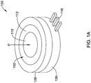
- Figure 1A is a perspective view of an illustrative pressure sensor assembly 100 with an integrated seal and diaphragm member 102.
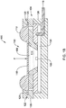
- Figure 1B is a schematic cross-sectional side view of the illustrative pressure sensor assembly 100 of Figure 1A
- Figure 1C is a exploded perspective view of the illustrative pressure sensor assembly 100 of Figure 1A .
- the illustrative pressure sensor assembly 100 includes a housing 104, a pressure sense die 106 secured relative to the housing 104, and an integrated seal and diaphragm member 102 secured relative to the housing 104 and spaced from the pressure sense die 106.
- a pressure transmitting mechanism 108 may be interposed between a diaphragm portion 110 of the integrated seal and diaphragm member 102 and the pressure sense die 106 for transmitting at least some of the pressure P applied to the diaphragm portion 110 by the media to the pressure sense die 106.
- a seal portion 112 of the integrated seal and diaphragm member 102 may extend around the perimeter of the diaphragm portion 110 as shown.
- the integrated seal and diaphragm member 102 may be injection molded as a single piece and may be formed of a flexible material such as a polymer. In some cases, the integrated seal and diaphragm member 102 may be formed from silicone. In some cases, the integrated seal and diaphragm member 102 may be integrally formed from two or more different materials. For example, in some cases, the diaphragm portion 110 may be formed from a flexible non-compressible material, and the seal portion 112 may be formed from a flexible compressible material. Both materials may be injection molded at the same time to form a unitary piece. In some instances, the seal portion 112 of the integrated seal and diaphragm member 102 may be thicker than the diaphragm portion 110 as shown.
- the seal portion 112 may be configured to engage a pressure port of an external component or device (not explicitly shown) and form a seal therewith, while the diaphragm portion 110 remains set back from the pressure port.
- the seal portion 112 may be shaped as a partial (e.g. 1/4, 1/3, 1/2, 3/4, etc.) toroid extending around the perimeter of the diaphragm portion 110, but this is not required.
- the diaphragm portion 110 and the housing 104 are configured to define a cavity 114.
- a pressure transmitting mechanism 108 may be transmit a pressure P applied to the diaphragm portion 110 to the pressure sense die 106. It is contemplated that the pressure transmitting mechanism 108 may include, for example, a ball bearing and/or any other suitable pressure transmitting mechanism.
- the pressure transmitting mechanism 108 may include a gel that fills the cavity 114 as indicated by the dot pattern, with the pressure sense die 106 exposed to the gel in the cavity 114. The gel may transmit the pressure P applied to the gel by the diaphragm portion 110 to the pressure sense die 106.
- the pressure sense die 106 may then converts the sensed pressure or force to an electrical signal that can be delivered via connector pins 118 to external electronic circuitry.
- the integrated seal and diaphragm member 102 may be configured so that the diaphragm portion 110 remains in contact with the gel in the cavity 114 with no bubbles between the gel and the diaphragm portion 110 even when the seal portion 112 becomes deformed when forming a seal with a pressure port of an external component or device.
- the integrated seal and diaphragm member 102 is configured such that deformation of the seal portion 112 against a pressure port of an external component or device encourages the diaphragm portion 110 to remaining in contact with the gel or at least not pull away from the gel 108, and perhaps increases the lateral tension of the diaphragm portion 110 across the cavity 114.
- the integrated seal and diaphragm member 102 may include one or more retention features 120 that form an interference connection with one or more retention features 122 (e.g. slot) of the housing 104. This may allow for easier assembly of the integrated seal and diaphragm member 102 with the housing 104.
- the housing 104 may include a base 126 and a cap 128, wherein the cap 128 is secured to the base 126.
- the cap 128 includes one or more retention features 122 for forming an interference connection with one or more retention features 120 of the integrated seal and diaphragm member 102.
- the housing 104 may be a one-piece housing (see Figure 2 ) and one or more retention features 222 may be provided by the one-piece housing 104.
- a printed circuit board 130 or the like may be secured relative to the housing 104, and the pressure sense die 106 may be mounted to the printed circuit board 130.
- the printed circuit board 130 may be considered to be part of the housing 104 or may be considered to be a separate component.
- the printed circuit board 130 may be positioned to expose the pressure sense die 106 to the pressure transmitting mechanism (e.g. gel in the cavity 114).
- the printed circuit board 130 is insert molded within the housing 104, and may be considered part of the housing 104, and may define part of the cavity 114.
- the pressure sensor assembly 100 may include a body (e.g. housing 104) defining the cavity 114 with an open top.
- the pressure sense die 106 may be secured relative to the body (housing 104) and may be exposed to the cavity 114 as shown.
- the integrated seal and diaphragm member 102 may be secured relative to the body so as to close the open top of the cavity 114.
- a gel may be placed in the cavity 114, interposed between the diaphragm portion 110 of the integrated seal and diaphragm member 102 and the pressure sense die 106.
- the seal portion 112 may extend around the perimeter of the cavity 114 and around the diaphragm portion 110, and the diaphragm portion 110 may extend over the open top of the cavity 114 as shown.
- the seal portion 112 rests against and is supported by the body when the seal portion 112 is pressed against a pressure port to form a seal.
- the integrated seal and diaphragm member 102 may include a diaphragm portion 110, a seal portion 112 integral with the diaphragm portion 110, and in some cases one or more retention features 120 integral with the diaphragm portion 110 and/or the seal portion 112.
- the seal portion 112 may be thicker than the diaphragm portion 110 and may extend around the perimeter of the diaphragm portion 110.
- the one or more retention features 120 may be configured to form an interference connection with one or more retention features 122 of a pressure sensor assembly.
- the seal portion 112 may be configured to deform to form a seal with a pressure port of an external component or device without causing the diaphragm portion 110 to move toward the pressure port in any significant way (e.g. less than 2mm maximum deflection toward the pressure port).
- FIG 2 is a schematic cross-sectional side view of another example pressure sensor assembly 200 with an integrated seal and diaphragm member 202.
- the illustrative pressure sensor assembly 200 is similar to the pressure sensor assembly 100 shown in Figures 1A-1C , except that the housing 204 is shown as a one-piece housing.
- the printed circuit board 230 is not insert molded within the housing 204, but rather is mounted to the back of the housing 104 and in some cases forms the back of the cavity 214.
- the printed circuit board 230 may be considered to be part of the housing 204 or may be considered to be a separate component.
- the printed circuit board 230 may be positioned to expose the pressure sensor die 206, which is mounted to the printed circuit board 230, to the pressure transmitting mechanism (e.g. a gel in the cavity 214).
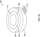
- Figure 3A is a perspective view of another illustrative pressure sensor assembly 300 with an integrated seal and diaphragm member.
- Figure 3B is a schematic cross-sectional side view of the illustrative pressure sensor assembly 300 of Figure 3A
- Figure 3C is a exploded perspective view of the illustrative pressure sensor assembly 300 of Figure 3A .
- the illustrative pressure sensor assembly 300 is similar to the pressure sensor assembly 100 shown in Figures 1A-1C , except that the seal 312 is a separate component from the diaphragm 310. That is, the seal 312 and diaphragm 310 are not integrated. This illustrative pressure sensor assembly 300 may be more difficult to assembly than that shown in Figures 1A-1C .
- the seal 312 may be an O-ring seal 312 that is partially inset within a cavity defined in the housing 304.
- the cavity of the housing 304 may be defined by lateral edges 360 that may extend inward at or near the top (in the orientation of Figure 3B ) as shown at 361 in order to reduce the lateral dimension of the cavity at or near the top to help hold the O-ring seal 312 within the cavity once installed.
- spaced tabs 364 may be provided that extend inward to help retain the O-ring seal 312 within the cavity.
- the diaphragm 310 may be placed in the cavity, followed by the O-ring seal 312.
- the O-ring seal 312 may be pressed past the inward extending tabs 364 (or inward extending walls) of the housing 304 so that the diaphragm 310 and O-ring seal 312 are retained within the cavity of the housing 304.
- Part of the O-ring seal 312 may remain outside of the housing 304 to engage and form a seal with a pressure port of an external component or device.
- Figures 4A-6B are schematic cross-sectional side views of illustrative mounting structures for mounting pressure sensor assemblies, such as those shown in Figures 1-3 , to an external component or device.
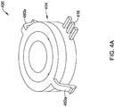
- Figure 4A is a perspective view of an illustrative pressure sensor assembly with a mounting structure for mounting the pressure sensor assembly to an external component or device.
- Figure 4B is a schematic cross-sectional side view of the illustrative pressure sensor assembly of Figure 4A mounted to an external component or device.
- the housing 404 includes opposing wing-clips 460a and 460b. While two wing-clips 460a and 460b are shown, it is contemplated more or less wing clips may be provided.
- the two wing-clips 460a and 460b may be configured to bend inward when the pressure sensor assembly 400 is pressed into a receiving receptacle 464 (see Figure 4B ), and may snap outward to engage engaging features 470a and 470b of the receptacle 464, respectively. This may provide an easy yet secure way to mount the pressure sensor assembly 400. It is contemplated that any of the example pressure sensor assemblies of Figures 1A-3C may be mounted using such wing-clips 460a and 460b.
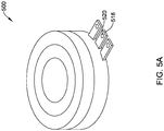
- Figure 5A is a perspective view of another illustrative pressure sensor assembly 500 with a mounting structure for mounting the pressure sensor assembly to an external component or device.
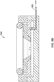
- Figure 5B is a schematic cross-sectional side view of the illustrative pressure sensor assembly 500 of Figure 5A .
- the illustrative pressure sensor assembly 500 may include connector pins 518 extending away from the housing.
- One or more of the connector pints 518 may include rivet apertures 520.
- the illustrative pressure sensor assembly 500 may be mounted to an external component or device via rivets that pass through the rivet apertures 520 as shown.
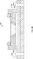
- Figure 6A is a perspective view of another illustrative pressure sensor assembly 600 with another mounting structure for mounting the pressure sensor assembly 600 to an external component or device.
- Figure 6B is a schematic cross-sectional side view of the illustrative pressure sensor assembly 600 of Figure 6A mounted to an external component or device.
- the illustrative pressure sensor assembly 600 may include a housing 604 that includes opposing mounting tabs 660a and 660b. While two mounting tabs 660a and 660b are shown, it is contemplated more or less mounting tabs may be provided. Each of the two mounting tabs 660a and 660b may include an aperture 662a and 662b, respectively. Heat stakes 664a and 664b, screws or any other fastener, may pass through each of the aperture 662a and 662b to heat stake (other otherwise mount) the pressure sensor assembly 600 to a mounting surface.
Landscapes
- Physics & Mathematics (AREA)
- General Physics & Mathematics (AREA)
- Chemical & Material Sciences (AREA)
- Analytical Chemistry (AREA)
- Measuring Fluid Pressure (AREA)
Abstract
Description
- The disclosure relates generally to pressure sensors used for sensing a pressure of a media in a pressure port, and more particularly, to an improved interface between a pressure sensor and the pressure port.
- Pressure sensors are utilized in a wide variety of applications, including, for example, commercial, automotive, aerospace, industrial, and medical applications. In many applications, the operational environments in which pressure sensors are required to operate with high accuracy and repeatability can be very demanding. In addition, pressure sensors are often expected to sense and/or monitor a pressure of a harsh and/or corrosive media such as an acid, chemicals, gasoline, oil, transmission fluid, and/or other harsh media.
- In many cases, a pressure sensor must interface with a pressure port of an external component or device, such as an engine, transmission, industrial piping, or other external component or device. To do so, a seal is provided between the pressure sensor and the pressure port. The seal helps contain the media while exposing the pressure sensor to the pressure of the media.
- Pressure sensors often includes a pressure sense die that converts the sensed pressure to an electrical signal that can be used by external electronic circuitry such as a control system or the like. In many cases, the pressure sense die is isolated from the media by a diaphragm or the like. When so provided, the diaphragm may transmit pressure applied by the media to the pressure sense die or to an intervening pressure transmitting mechanism that transmits the pressure applied by the media to the pressure sense die. The intervening pressure transmitting mechanism may include, for example, a gel, a ball bearing and/or any other suitable pressure transmitting mechanism.
- What would be desirable is an improved interface between the pressure sensor and a pressure port of an external component or device.
- The disclosure relates generally to pressure sensors used for sensing a pressure of a media in a pressure port, and more particularly, to an improved interface between a pressure sensor and the pressure port.
- In one example, a pressure sensor assembly may include a housing, a pressure sense die secured relative to the housing, an integrated seal and diaphragm member secured relative to the housing and spaced from the pressure sense die, and a pressure transmitting mechanism interposed between a diaphragm portion of the integrated seal and diaphragm member and the pressure sense die. The diaphragm portion may be configured to transmit at least some of the pressure applied to the diaphragm portion by the media either directly or indirectly (e.g. via a pressure transmitting mechanism) to the pressure sense die. In some cases, a seal portion of the integrated seal and diaphragm member may extend around the perimeter of the diaphragm portion and may be supported by the housing when the seal portion is pressed against a pressure port to form a seal.
- The integrated seal and diaphragm member may be injection molded as a single piece and may be formed of a flexible material such as a polymer or the like. In some cases, the integrated seal and diaphragm member may be formed from silicone. In some cases, the integrated seal and diaphragm member may be integrally formed from two or more different materials. For example, in some cases, a diaphragm portion may be formed from a flexible non-compressible material, and a seal portion may be formed from a flexible compressible material. Both materials may be injection molded at the same time to form a unitary piece. In some instances, the seal portion of the integrated seal and diaphragm member may be thicker than the diaphragm portion. In some cases, the seal portion may be configured to engage a pressure port of an external component or device and form a seal therewith, while the diaphragm portion is set back from the pressure port. In some cases, the seal portion may be shaped as a partial toroid extending around the perimeter of the diaphragm portion, but this is not required.
- In some cases, the diaphragm portion and the housing are configured to define a cavity. The cavity may be filled with a gel or the like, with the pressure sense die exposed to the gel in the cavity. The gel may transmit a pressure applied to the gel by the diaphragm portion to the pressure sense die. The pressure sense die may converts the sensed pressure to an electrical signal that can be used by external electronic circuitry. In some cases, the integrated seal and diaphragm member may be configured so that the diaphragm portion remains in contact with the gel with no bubbles between the gel and the diaphragm portion even when the seal portion becomes deformed when forming a seal with a pressure port of an external component or device. In some cases, the integrated seal and diaphragm member is configured such that deformation of the seal portion against a pressure port of an external component or device encourages the diaphragm portion to remaining in contact with the gel or at least not pull away from the gel, and perhaps increases the lateral tension of the diaphragm portion across the cavity.
- In some cases, the integrated seal and diaphragm member may include one or more retention features that form an interference connection with one or more retention features of the housing. This may allow for easier assembly of the integrated seal and diaphragm member with the housing. In some cases, the housing may include a base and a cap, with the cap secured to the base. In some cases, the cap may include one or more retention features for forming an interference connection with the one or more retention features of the integrated seal and diaphragm member. In other cases, the housing may be a one-piece housing.
- In some cases, the pressure sensor assembly may include a printed circuit board secured relative to the housing. When so provided, the pressure sense die may be mounted to the printed circuit board. In some cases, the printed circuit board may be considered as part of the housing or may be considered as a separate component. The printed circuit board may be positioned to expose the pressure sensor die to the pressure transmitting mechanism (e.g. gel).
- In another example, a pressure sensor assembly may include a body defining a cavity that has an open top, a pressure sense die secured relative to the body and exposed to the cavity, an integrated seal and diaphragm member secured relative to the body so as to close the open top of the cavity, and a gel in the cavity interposed between ae diaphragm portion of the integrated seal and diaphragm member and the pressure sense die. In some cases, a seal portion of the integrated seal and diaphragm member may extend around the perimeter of the cavity so as to be supported by the body, and the diaphragm portion may extend over the open top of the cavity.
- In another example, an integrated seal and diaphragm member for a pressure sensor assembly may include a diaphragm portion, a seal portion integral with the diaphragm portion, and one or more retention features integral with the diaphragm portion and/or the seal portion. In some cases, the seal portion may be thicker than the diaphragm portion and may extend around the perimeter of the diaphragm portion. In some cases, the one or more retention features may be configured to form an interference connection with one or more retention features of a pressure sensor assembly. In some instances, the seal portion may be configured to deform to form a seal with a pressure port of an external component or device without causing the diaphragm portion to move toward the pressure port in any significant way.
- The above summary is not intended to describe each and every disclosed illustrative example or every implementation of the disclosure. The Description that follows more particularly exemplifies various illustrative embodiments.
- The following description should be read with reference to the drawings. The drawings, which are not necessarily to scale, depict selected illustrative embodiments and are not intended to limit the scope of the disclosure. The disclosure may be more completely understood in consideration of the following description of various illustrative embodiments in connection with the accompanying drawings, in which:
-
Figure 1A is a perspective view of an illustrative pressure sensor assembly with an integrated seal and diaphragm member; -
Figure 1B is a schematic cross-sectional side view of the illustrative pressure sensor assembly ofFigure 1A ; -
Figure 1C is a exploded perspective view of the illustrative pressure sensor assembly ofFigure 1A ; -
Figure 2 is a schematic cross-sectional side view of another example pressure sensor assembly with an integrated seal and diaphragm member; -
Figure 3A is a perspective view of another illustrative pressure sensor assembly with an integrated seal and diaphragm member; -
Figure 3B is a schematic cross-sectional side view of the illustrative pressure sensor assembly ofFigure 3A ; -
Figure 3C is a exploded perspective view of the illustrative pressure sensor assembly ofFigure 3A ; -
Figure 4A is a perspective view of another illustrative pressure sensor assembly with a mounting structure for mounting the pressure sensor assembly to an external component or device; -
Figure 4B is a schematic cross-sectional side view of the illustrative pressure sensor assembly ofFigure 4A mounted to an external component or device; -
Figure 5A is a perspective view of another illustrative pressure sensor assembly with a mounting structure for mounting the pressure sensor assembly to an external component or device; -
Figure 5B is a schematic cross-sectional side view of the illustrative pressure sensor assembly ofFigure 5A ; -
Figure 6A is a perspective view of another illustrative pressure sensor assembly with a mounting structure for mounting the pressure sensor assembly to an external component or device; and -
Figure 6B is a schematic cross-sectional side view of the illustrative pressure sensor assembly ofFigure 6A mounted to an external component or device. - The following description should be read with reference to the drawings, in which like elements in different drawings are numbered in like fashion. The drawings, which are not necessarily to scale, depict selected illustrative embodiments and are not intended to limit the scope of the disclosure. Although examples of construction, dimensions, and materials are illustrated for the various elements, those skilled in the art will recognize that many of the examples provided have suitable alternatives that may be utilized.
-
Figure 1A is a perspective view of an illustrativepressure sensor assembly 100 with an integrated seal anddiaphragm member 102.Figure 1B is a schematic cross-sectional side view of the illustrativepressure sensor assembly 100 ofFigure 1A , andFigure 1C is a exploded perspective view of the illustrativepressure sensor assembly 100 ofFigure 1A . The illustrativepressure sensor assembly 100 includes ahousing 104, a pressure sense die 106 secured relative to thehousing 104, and an integrated seal anddiaphragm member 102 secured relative to thehousing 104 and spaced from the pressure sense die 106. Apressure transmitting mechanism 108 may be interposed between adiaphragm portion 110 of the integrated seal anddiaphragm member 102 and the pressure sense die 106 for transmitting at least some of the pressure P applied to thediaphragm portion 110 by the media to the pressure sense die 106. In some cases, aseal portion 112 of the integrated seal anddiaphragm member 102 may extend around the perimeter of thediaphragm portion 110 as shown. - The integrated seal and
diaphragm member 102 may be injection molded as a single piece and may be formed of a flexible material such as a polymer. In some cases, the integrated seal anddiaphragm member 102 may be formed from silicone. In some cases, the integrated seal anddiaphragm member 102 may be integrally formed from two or more different materials. For example, in some cases, thediaphragm portion 110 may be formed from a flexible non-compressible material, and theseal portion 112 may be formed from a flexible compressible material. Both materials may be injection molded at the same time to form a unitary piece. In some instances, theseal portion 112 of the integrated seal anddiaphragm member 102 may be thicker than thediaphragm portion 110 as shown. In some cases, theseal portion 112 may be configured to engage a pressure port of an external component or device (not explicitly shown) and form a seal therewith, while thediaphragm portion 110 remains set back from the pressure port. In some cases, theseal portion 112 may be shaped as a partial (e.g. 1/4, 1/3, 1/2, 3/4, etc.) toroid extending around the perimeter of thediaphragm portion 110, but this is not required. - In some cases, the
diaphragm portion 110 and thehousing 104 are configured to define acavity 114. Apressure transmitting mechanism 108 may be transmit a pressure P applied to thediaphragm portion 110 to the pressure sense die 106. It is contemplated that thepressure transmitting mechanism 108 may include, for example, a ball bearing and/or any other suitable pressure transmitting mechanism. In some cases, thepressure transmitting mechanism 108 may include a gel that fills thecavity 114 as indicated by the dot pattern, with the pressure sense die 106 exposed to the gel in thecavity 114. The gel may transmit the pressure P applied to the gel by thediaphragm portion 110 to the pressure sense die 106. The pressure sense die 106 may then converts the sensed pressure or force to an electrical signal that can be delivered via connector pins 118 to external electronic circuitry. In some cases, the integrated seal anddiaphragm member 102 may be configured so that thediaphragm portion 110 remains in contact with the gel in thecavity 114 with no bubbles between the gel and thediaphragm portion 110 even when theseal portion 112 becomes deformed when forming a seal with a pressure port of an external component or device. In some cases, the integrated seal anddiaphragm member 102 is configured such that deformation of theseal portion 112 against a pressure port of an external component or device encourages thediaphragm portion 110 to remaining in contact with the gel or at least not pull away from thegel 108, and perhaps increases the lateral tension of thediaphragm portion 110 across thecavity 114. - In some cases, the integrated seal and
diaphragm member 102 may include one or more retention features 120 that form an interference connection with one or more retention features 122 (e.g. slot) of thehousing 104. This may allow for easier assembly of the integrated seal anddiaphragm member 102 with thehousing 104. In some cases, thehousing 104 may include abase 126 and acap 128, wherein thecap 128 is secured to thebase 126. In some cases, thecap 128 includes one or more retention features 122 for forming an interference connection with one or more retention features 120 of the integrated seal anddiaphragm member 102. In other cases, thehousing 104 may be a one-piece housing (seeFigure 2 ) and one or more retention features 222 may be provided by the one-piece housing 104. - In some cases, a printed
circuit board 130 or the like may be secured relative to thehousing 104, and the pressure sense die 106 may be mounted to the printedcircuit board 130. The printedcircuit board 130 may be considered to be part of thehousing 104 or may be considered to be a separate component. The printedcircuit board 130 may be positioned to expose the pressure sense die 106 to the pressure transmitting mechanism (e.g. gel in the cavity 114). In the example shown inFigures 1A-1C , the printedcircuit board 130 is insert molded within thehousing 104, and may be considered part of thehousing 104, and may define part of thecavity 114. - More generally, the
pressure sensor assembly 100 may include a body (e.g. housing 104) defining thecavity 114 with an open top. The pressure sense die 106 may be secured relative to the body (housing 104) and may be exposed to thecavity 114 as shown. The integrated seal anddiaphragm member 102 may be secured relative to the body so as to close the open top of thecavity 114. A gel may be placed in thecavity 114, interposed between thediaphragm portion 110 of the integrated seal anddiaphragm member 102 and the pressure sense die 106. In some cases, theseal portion 112 may extend around the perimeter of thecavity 114 and around thediaphragm portion 110, and thediaphragm portion 110 may extend over the open top of thecavity 114 as shown. In some cases, theseal portion 112 rests against and is supported by the body when theseal portion 112 is pressed against a pressure port to form a seal. - As detailed above, the integrated seal and
diaphragm member 102 may include adiaphragm portion 110, aseal portion 112 integral with thediaphragm portion 110, and in some cases one or more retention features 120 integral with thediaphragm portion 110 and/or theseal portion 112. In some cases, theseal portion 112 may be thicker than thediaphragm portion 110 and may extend around the perimeter of thediaphragm portion 110. In some cases, the one or more retention features 120 may be configured to form an interference connection with one or more retention features 122 of a pressure sensor assembly. In some instances, theseal portion 112 may be configured to deform to form a seal with a pressure port of an external component or device without causing thediaphragm portion 110 to move toward the pressure port in any significant way (e.g. less than 2mm maximum deflection toward the pressure port). -
Figure 2 is a schematic cross-sectional side view of another examplepressure sensor assembly 200 with an integrated seal anddiaphragm member 202. The illustrativepressure sensor assembly 200 is similar to thepressure sensor assembly 100 shown inFigures 1A-1C , except that thehousing 204 is shown as a one-piece housing. Also, the printedcircuit board 230 is not insert molded within thehousing 204, but rather is mounted to the back of thehousing 104 and in some cases forms the back of thecavity 214. The printedcircuit board 230 may be considered to be part of thehousing 204 or may be considered to be a separate component. The printedcircuit board 230 may be positioned to expose the pressure sensor die 206, which is mounted to the printedcircuit board 230, to the pressure transmitting mechanism (e.g. a gel in the cavity 214). -
Figure 3A is a perspective view of another illustrativepressure sensor assembly 300 with an integrated seal and diaphragm member.Figure 3B is a schematic cross-sectional side view of the illustrativepressure sensor assembly 300 ofFigure 3A , andFigure 3C is a exploded perspective view of the illustrativepressure sensor assembly 300 ofFigure 3A . The illustrativepressure sensor assembly 300 is similar to thepressure sensor assembly 100 shown inFigures 1A-1C , except that theseal 312 is a separate component from thediaphragm 310. That is, theseal 312 anddiaphragm 310 are not integrated. This illustrativepressure sensor assembly 300 may be more difficult to assembly than that shown inFigures 1A-1C . In the example shown inFigures 3A-3C , theseal 312 may be an O-ring seal 312 that is partially inset within a cavity defined in thehousing 304. The cavity of thehousing 304 may be defined bylateral edges 360 that may extend inward at or near the top (in the orientation ofFigure 3B ) as shown at 361 in order to reduce the lateral dimension of the cavity at or near the top to help hold the O-ring seal 312 within the cavity once installed. In some cases, rather than the entire circumference of the cavity extending inward, spaced tabs 364 (seeFigure 3C ) may be provided that extend inward to help retain the O-ring seal 312 within the cavity. During assembly, thediaphragm 310 may be placed in the cavity, followed by the O-ring seal 312. The O-ring seal 312 may be pressed past the inward extending tabs 364 (or inward extending walls) of thehousing 304 so that thediaphragm 310 and O-ring seal 312 are retained within the cavity of thehousing 304. Part of the O-ring seal 312 may remain outside of thehousing 304 to engage and form a seal with a pressure port of an external component or device. -
Figures 4A-6B are schematic cross-sectional side views of illustrative mounting structures for mounting pressure sensor assemblies, such as those shown inFigures 1-3 , to an external component or device.Figure 4A is a perspective view of an illustrative pressure sensor assembly with a mounting structure for mounting the pressure sensor assembly to an external component or device.Figure 4B is a schematic cross-sectional side view of the illustrative pressure sensor assembly ofFigure 4A mounted to an external component or device. InFigures 4A-4B , thehousing 404 includes opposing wing-clips clips clips pressure sensor assembly 400 is pressed into a receiving receptacle 464 (seeFigure 4B ), and may snap outward to engage engagingfeatures 470a and 470b of thereceptacle 464, respectively. This may provide an easy yet secure way to mount thepressure sensor assembly 400. It is contemplated that any of the example pressure sensor assemblies ofFigures 1A-3C may be mounted using such wing-clips -
Figure 5A is a perspective view of another illustrativepressure sensor assembly 500 with a mounting structure for mounting the pressure sensor assembly to an external component or device.Figure 5B is a schematic cross-sectional side view of the illustrativepressure sensor assembly 500 ofFigure 5A . The illustrativepressure sensor assembly 500 may include connector pins 518 extending away from the housing. One or more of theconnector pints 518 may includerivet apertures 520. When so provided, the illustrativepressure sensor assembly 500 may be mounted to an external component or device via rivets that pass through therivet apertures 520 as shown. -
Figure 6A is a perspective view of another illustrativepressure sensor assembly 600 with another mounting structure for mounting thepressure sensor assembly 600 to an external component or device.Figure 6B is a schematic cross-sectional side view of the illustrativepressure sensor assembly 600 ofFigure 6A mounted to an external component or device. InFigures 6A-6B , the illustrativepressure sensor assembly 600 may include ahousing 604 that includes opposing mountingtabs tabs tabs aperture Heat stakes aperture pressure sensor assembly 600 to a mounting surface. - The disclosure should not be considered limited to the particular examples described above. Various modifications, equivalent processes, as well as numerous structures to which the disclosure can be applicable will be readily apparent to those of skill in the art upon review of the instant specification.
Claims (15)
- A pressure sensor assembly for sensing a pressure of a media, comprising:a housing;a pressure sense die secured relative to the housing;an integrated seal and diaphragm member secured relative to the housing and spaced from the pressure sense die, wherein a seal portion of the integrated seal and diaphragm memberextends around the perimeter of a diaphragm portion of the integrated seal and diaphragm member; anda pressure transmitting mechanism interposed between the diaphragm portion of the integrated seal and diaphragm member and the pressure sense die for transmitting at least some of the pressure applied to the diaphragm portion by the media to the pressure sense die.
- The pressure sensor assembly of claim 1, wherein the integrated seal and diaphragm member is a single piece.
- The pressure sensor assembly of claim 1, wherein the integrated seal and diaphragm member is a single piece formed from a polymer.
- The pressure sensor assembly of claim 1, wherein the seal portion of the integrated seal and diaphragm member is thicker than the diaphragm portion of the integrated seal and diaphragm member.
- The pressure sensor assembly of claim 4, wherein the seal portion is configured to engage a pressure port of an external component or device and form a seal, while the diaphragm portion is set back from the pressure port.
- The pressure sensor assembly of claim 1, wherein the diaphragm portion and the housing are configured to define a cavity, wherein the pressure transmitting mechanism comprises a gel that fills the cavity and the pressure sense die is exposed to the gel in the cavity.
- The pressure sensor assembly of claim 6, wherein the integrated seal and diaphragm member is configured so that the diaphragm portion remains in contact with the gel with no bubbles between the gel and the diaphragm portion even when the seal portion deforms to form a seal with a pressure port of an external component or device.
- The pressure sensor assembly of claim 7, wherein the integrated seal and diaphragm member is configured such that deformation of the seal portion against a pressure port of an external component or device encourages the diaphragm portion to remaining in contact with the gel.
- The pressure sensor assembly of claim 7, wherein the integrated seal and diaphragm member is configured such that deformation of the seal portion against a pressure port of an external component or device does not cause the diaphragm portion to pull away from the gel.
- The pressure sensor assembly of claim 1, wherein the seal portion is shaped as a partial toroid extending around the perimeter of the diaphragm portion.
- The pressure sensor assembly of claim 1, wherein the integrated seal and diaphragm member comprises one or more retention features that form an interference connection with one or more retention features of the housing.
- The pressure sensor assembly of claim 11, wherein the housing comprises a base and a cap, wherein the cap is secured to the base, and wherein the cap comprises the one or more retention features of the housing.
- A pressure sensor assembly for sensing a pressure of a media in a pressure port of an external component or device, comprising:a body defining a cavity with an open top;a pressure sense die secured relative to the body and exposed to the cavity;an integrated seal and diaphragm member secured relative to the body closing the open top of the cavity;a gel in the cavity interposed between a diaphragm portion of the integrated seal and diaphragm member and the pressure sense die.
- The pressure sensor assembly of claim 13, wherein a seal portion of the integrated seal and diaphragm member extends around the perimeter of the cavity, and the diaphragm portion extends over the open top of the cavity.
- The pressure sensor assembly of claim 14, wherein the seal portion is supported by the body when the seal portion is pressed against the pressure port of an external component or device to form a seal.
Applications Claiming Priority (2)
| Application Number | Priority Date | Filing Date | Title |
|---|---|---|---|
| US201762612237P | 2017-12-29 | 2017-12-29 | |
| US16/207,944 US10837852B2 (en) | 2017-12-29 | 2018-12-03 | Pressure sensor media interface with integrated seal and diaphragm |
Publications (3)
| Publication Number | Publication Date |
|---|---|
| EP3514517A2 true EP3514517A2 (en) | 2019-07-24 |
| EP3514517A3 EP3514517A3 (en) | 2019-10-02 |
| EP3514517B1 EP3514517B1 (en) | 2022-02-02 |
Family
ID=64949088
Family Applications (1)
| Application Number | Title | Priority Date | Filing Date |
|---|---|---|---|
| EP18215807.1A Not-in-force EP3514517B1 (en) | 2017-12-29 | 2018-12-21 | Pressure sensor media interface with integrated seal and diaphragm |
Country Status (3)
| Country | Link |
|---|---|
| US (1) | US10837852B2 (en) |
| EP (1) | EP3514517B1 (en) |
| CN (1) | CN109990943A (en) |
Families Citing this family (1)
| Publication number | Priority date | Publication date | Assignee | Title |
|---|---|---|---|---|
| WO2022070571A1 (en) * | 2020-09-30 | 2022-04-07 | 株式会社村田製作所 | Pressure sensor and method for manufacturing same |
Family Cites Families (17)
| Publication number | Priority date | Publication date | Assignee | Title |
|---|---|---|---|---|
| US4768382A (en) * | 1987-04-23 | 1988-09-06 | Honeywell Inc. | Method of producing a uniform fluid-tight seal between a thin, flexible member and a support and an apparatus utilizing the same |
| US4926155A (en) * | 1988-12-12 | 1990-05-15 | Johnson Service Company | Integrated circuit silicon pressure transducer package |
| JPH02280026A (en) * | 1989-04-20 | 1990-11-16 | Nippondenso Co Ltd | Semiconductor type pressure detecting device |
| US5708245A (en) | 1992-07-14 | 1998-01-13 | Texas Instruments Incorporated | Normally open pressure responsive switch |
| FI952881A0 (en) | 1994-06-17 | 1995-06-13 | Instrumentarium Oy | Foerfarande Foer fastspaenning av ett membran och anordning Foer genomfoerande av foerfarandet |
| US7021148B2 (en) * | 2002-04-30 | 2006-04-04 | Baxter International Inc. | Apparatus and method for sealing pressure sensor membranes |
| US6886929B2 (en) | 2002-10-25 | 2005-05-03 | Hewlett-Packard Development Company, L.P. | Techniques for improving pressure sensor shock robustness in fluid containment devices |
| US7293464B1 (en) * | 2006-06-29 | 2007-11-13 | Chih-Chen Juan | Insulated IC pressure sensor |
| US7568394B1 (en) * | 2008-04-24 | 2009-08-04 | Cardiometrix, Inc. | Enhanced diaphragm for pressure sensing system and method |
| US8474824B2 (en) * | 2008-11-10 | 2013-07-02 | Eaton Corporation | Pressure sensing module having an integrated seal plate and method of assembling pressure sensing module |
| WO2010094265A1 (en) * | 2009-02-17 | 2010-08-26 | Armaturenbau Gmbh | Chemical seal |
| US8297127B2 (en) * | 2011-01-07 | 2012-10-30 | Honeywell International Inc. | Pressure sensor with low cost packaging |
| US8671766B2 (en) * | 2011-05-19 | 2014-03-18 | Infineon Technologies Ag | Integrated pressure sensor seal |
| CN103257007B (en) * | 2012-02-17 | 2015-07-08 | 苏州敏芯微电子技术有限公司 | Pressure sensor dielectric medium isolation packaging structure and packaging method of same |
| CN105547576A (en) * | 2015-12-08 | 2016-05-04 | 苏州敏芯微电子技术有限公司 | Medium-isolated pressure sensor packaging structure |
| ITUB20160759A1 (en) * | 2016-02-15 | 2017-08-15 | St Microelectronics Srl | ENCAPSULATED PRESSURE SENSOR IN ELASTOMERIC MATERIAL, AND SYSTEM INCLUDING THE PRESSURE SENSOR |
| US10094726B2 (en) * | 2017-02-01 | 2018-10-09 | Honeywell International Inc. | Membrane isolated, gel-filled force sensor |
-
2018
- 2018-12-03 US US16/207,944 patent/US10837852B2/en active Active
- 2018-12-21 EP EP18215807.1A patent/EP3514517B1/en not_active Not-in-force
- 2018-12-28 CN CN201811621210.7A patent/CN109990943A/en active Pending
Non-Patent Citations (1)
| Title |
|---|
| None |
Also Published As
| Publication number | Publication date |
|---|---|
| EP3514517A3 (en) | 2019-10-02 |
| US20190204173A1 (en) | 2019-07-04 |
| EP3514517B1 (en) | 2022-02-02 |
| US10837852B2 (en) | 2020-11-17 |
| CN109990943A (en) | 2019-07-09 |
Similar Documents
| Publication | Publication Date | Title |
|---|---|---|
| EP3176559B1 (en) | Pressure sensor | |
| US8316725B2 (en) | Force sensor | |
| EP2889599B1 (en) | Physical quantity measuring sensor and sensor module | |
| EP3002572A2 (en) | Physical quantity measuring device | |
| EP2474820B1 (en) | Pressure sensor with low cost packaging | |
| US10837852B2 (en) | Pressure sensor media interface with integrated seal and diaphragm | |
| US20190301959A1 (en) | Rectangular snap fit pressure sensor unit | |
| KR102752034B1 (en) | Pressure sensor unit having temperature sensor | |
| CN114878029A (en) | Pressure transmitter and mechanical equipment | |
| KR102818957B1 (en) | Pressure sensor unit | |
| CN109425445B (en) | Force sensor | |
| EP2927658B1 (en) | Physical quantity measuring device | |
| US10928264B2 (en) | Sensor assembly and liquid level detection device | |
| CN215573474U (en) | Sputtering film pressure sensor | |
| KR102678706B1 (en) | Pressure sensor unit | |
| TWI820218B (en) | Physical quantity measuring device | |
| JP5976302B2 (en) | Pressure detection device | |
| KR102434356B1 (en) | Pressure sensor unit | |
| KR102471049B1 (en) | Pressure sensor unit | |
| KR102678707B1 (en) | Pressure sensor unit | |
| KR20250100451A (en) | Pressure sensor unit having temperature sensor | |
| HK40020929A (en) | Physical quantity measuring sensor and sensor module | |
| JPH04113487U (en) | electrical equipment structure | |
| JPH0720696U (en) | Electrical equipment structure | |
| WO2007133953A2 (en) | Clamshell pressure sensor housing and methods for manufacturing same |
Legal Events
| Date | Code | Title | Description |
|---|---|---|---|
| PUAI | Public reference made under article 153(3) epc to a published international application that has entered the european phase |
Free format text: ORIGINAL CODE: 0009012 |
|
| STAA | Information on the status of an ep patent application or granted ep patent |
Free format text: STATUS: REQUEST FOR EXAMINATION WAS MADE |
|
| 17P | Request for examination filed |
Effective date: 20181221 |
|
| AK | Designated contracting states |
Kind code of ref document: A2 Designated state(s): AL AT BE BG CH CY CZ DE DK EE ES FI FR GB GR HR HU IE IS IT LI LT LU LV MC MK MT NL NO PL PT RO RS SE SI SK SM TR |
|
| AX | Request for extension of the european patent |
Extension state: BA ME |
|
| PUAL | Search report despatched |
Free format text: ORIGINAL CODE: 0009013 |
|
| AK | Designated contracting states |
Kind code of ref document: A3 Designated state(s): AL AT BE BG CH CY CZ DE DK EE ES FI FR GB GR HR HU IE IS IT LI LT LU LV MC MK MT NL NO PL PT RO RS SE SI SK SM TR |
|
| AX | Request for extension of the european patent |
Extension state: BA ME |
|
| RIC1 | Information provided on ipc code assigned before grant |
Ipc: G01L 19/06 20060101ALI20190829BHEP Ipc: G01L 19/00 20060101AFI20190829BHEP |
|
| STAA | Information on the status of an ep patent application or granted ep patent |
Free format text: STATUS: EXAMINATION IS IN PROGRESS |
|
| 17Q | First examination report despatched |
Effective date: 20200922 |
|
| GRAP | Despatch of communication of intention to grant a patent |
Free format text: ORIGINAL CODE: EPIDOSNIGR1 |
|
| STAA | Information on the status of an ep patent application or granted ep patent |
Free format text: STATUS: GRANT OF PATENT IS INTENDED |
|
| GRAJ | Information related to disapproval of communication of intention to grant by the applicant or resumption of examination proceedings by the epo deleted |
Free format text: ORIGINAL CODE: EPIDOSDIGR1 |
|
| GRAP | Despatch of communication of intention to grant a patent |
Free format text: ORIGINAL CODE: EPIDOSNIGR1 |
|
| STAA | Information on the status of an ep patent application or granted ep patent |
Free format text: STATUS: EXAMINATION IS IN PROGRESS |
|
| GRAJ | Information related to disapproval of communication of intention to grant by the applicant or resumption of examination proceedings by the epo deleted |
Free format text: ORIGINAL CODE: EPIDOSDIGR1 |
|
| GRAP | Despatch of communication of intention to grant a patent |
Free format text: ORIGINAL CODE: EPIDOSNIGR1 |
|
| STAA | Information on the status of an ep patent application or granted ep patent |
Free format text: STATUS: GRANT OF PATENT IS INTENDED |
|
| RIN1 | Information on inventor provided before grant (corrected) |
Inventor name: PATCH, JASON DENNIS Inventor name: ROZGO, PAUL |
|
| INTG | Intention to grant announced |
Effective date: 20210706 |
|
| INTG | Intention to grant announced |
Effective date: 20210721 |
|
| GRAS | Grant fee paid |
Free format text: ORIGINAL CODE: EPIDOSNIGR3 |
|
| GRAA | (expected) grant |
Free format text: ORIGINAL CODE: 0009210 |
|
| STAA | Information on the status of an ep patent application or granted ep patent |
Free format text: STATUS: THE PATENT HAS BEEN GRANTED |
|
| AK | Designated contracting states |
Kind code of ref document: B1 Designated state(s): AL AT BE BG CH CY CZ DE DK EE ES FI FR GB GR HR HU IE IS IT LI LT LU LV MC MK MT NL NO PL PT RO RS SE SI SK SM TR |
|
| REG | Reference to a national code |
Ref country code: GB Ref legal event code: FG4D |
|
| REG | Reference to a national code |
Ref country code: CH Ref legal event code: EP Ref country code: AT Ref legal event code: REF Ref document number: 1466703 Country of ref document: AT Kind code of ref document: T Effective date: 20220215 |
|
| REG | Reference to a national code |
Ref country code: DE Ref legal event code: R096 Ref document number: 602018030369 Country of ref document: DE |
|
| REG | Reference to a national code |
Ref country code: IE Ref legal event code: FG4D |
|
| REG | Reference to a national code |
Ref country code: LT Ref legal event code: MG9D |
|
| REG | Reference to a national code |
Ref country code: NL Ref legal event code: MP Effective date: 20220202 |
|
| REG | Reference to a national code |
Ref country code: AT Ref legal event code: MK05 Ref document number: 1466703 Country of ref document: AT Kind code of ref document: T Effective date: 20220202 |
|
| PG25 | Lapsed in a contracting state [announced via postgrant information from national office to epo] |
Ref country code: SE Free format text: LAPSE BECAUSE OF FAILURE TO SUBMIT A TRANSLATION OF THE DESCRIPTION OR TO PAY THE FEE WITHIN THE PRESCRIBED TIME-LIMIT Effective date: 20220202 Ref country code: RS Free format text: LAPSE BECAUSE OF FAILURE TO SUBMIT A TRANSLATION OF THE DESCRIPTION OR TO PAY THE FEE WITHIN THE PRESCRIBED TIME-LIMIT Effective date: 20220202 Ref country code: PT Free format text: LAPSE BECAUSE OF FAILURE TO SUBMIT A TRANSLATION OF THE DESCRIPTION OR TO PAY THE FEE WITHIN THE PRESCRIBED TIME-LIMIT Effective date: 20220602 Ref country code: NO Free format text: LAPSE BECAUSE OF FAILURE TO SUBMIT A TRANSLATION OF THE DESCRIPTION OR TO PAY THE FEE WITHIN THE PRESCRIBED TIME-LIMIT Effective date: 20220502 Ref country code: NL Free format text: LAPSE BECAUSE OF FAILURE TO SUBMIT A TRANSLATION OF THE DESCRIPTION OR TO PAY THE FEE WITHIN THE PRESCRIBED TIME-LIMIT Effective date: 20220202 Ref country code: LT Free format text: LAPSE BECAUSE OF FAILURE TO SUBMIT A TRANSLATION OF THE DESCRIPTION OR TO PAY THE FEE WITHIN THE PRESCRIBED TIME-LIMIT Effective date: 20220202 Ref country code: HR Free format text: LAPSE BECAUSE OF FAILURE TO SUBMIT A TRANSLATION OF THE DESCRIPTION OR TO PAY THE FEE WITHIN THE PRESCRIBED TIME-LIMIT Effective date: 20220202 Ref country code: ES Free format text: LAPSE BECAUSE OF FAILURE TO SUBMIT A TRANSLATION OF THE DESCRIPTION OR TO PAY THE FEE WITHIN THE PRESCRIBED TIME-LIMIT Effective date: 20220202 Ref country code: BG Free format text: LAPSE BECAUSE OF FAILURE TO SUBMIT A TRANSLATION OF THE DESCRIPTION OR TO PAY THE FEE WITHIN THE PRESCRIBED TIME-LIMIT Effective date: 20220502 |
|
| PG25 | Lapsed in a contracting state [announced via postgrant information from national office to epo] |
Ref country code: PL Free format text: LAPSE BECAUSE OF FAILURE TO SUBMIT A TRANSLATION OF THE DESCRIPTION OR TO PAY THE FEE WITHIN THE PRESCRIBED TIME-LIMIT Effective date: 20220202 Ref country code: LV Free format text: LAPSE BECAUSE OF FAILURE TO SUBMIT A TRANSLATION OF THE DESCRIPTION OR TO PAY THE FEE WITHIN THE PRESCRIBED TIME-LIMIT Effective date: 20220202 Ref country code: GR Free format text: LAPSE BECAUSE OF FAILURE TO SUBMIT A TRANSLATION OF THE DESCRIPTION OR TO PAY THE FEE WITHIN THE PRESCRIBED TIME-LIMIT Effective date: 20220503 Ref country code: FI Free format text: LAPSE BECAUSE OF FAILURE TO SUBMIT A TRANSLATION OF THE DESCRIPTION OR TO PAY THE FEE WITHIN THE PRESCRIBED TIME-LIMIT Effective date: 20220202 Ref country code: AT Free format text: LAPSE BECAUSE OF FAILURE TO SUBMIT A TRANSLATION OF THE DESCRIPTION OR TO PAY THE FEE WITHIN THE PRESCRIBED TIME-LIMIT Effective date: 20220202 |
|
| PG25 | Lapsed in a contracting state [announced via postgrant information from national office to epo] |
Ref country code: IS Free format text: LAPSE BECAUSE OF FAILURE TO SUBMIT A TRANSLATION OF THE DESCRIPTION OR TO PAY THE FEE WITHIN THE PRESCRIBED TIME-LIMIT Effective date: 20220602 |
|
| PG25 | Lapsed in a contracting state [announced via postgrant information from national office to epo] |
Ref country code: SM Free format text: LAPSE BECAUSE OF FAILURE TO SUBMIT A TRANSLATION OF THE DESCRIPTION OR TO PAY THE FEE WITHIN THE PRESCRIBED TIME-LIMIT Effective date: 20220202 Ref country code: SK Free format text: LAPSE BECAUSE OF FAILURE TO SUBMIT A TRANSLATION OF THE DESCRIPTION OR TO PAY THE FEE WITHIN THE PRESCRIBED TIME-LIMIT Effective date: 20220202 Ref country code: RO Free format text: LAPSE BECAUSE OF FAILURE TO SUBMIT A TRANSLATION OF THE DESCRIPTION OR TO PAY THE FEE WITHIN THE PRESCRIBED TIME-LIMIT Effective date: 20220202 Ref country code: EE Free format text: LAPSE BECAUSE OF FAILURE TO SUBMIT A TRANSLATION OF THE DESCRIPTION OR TO PAY THE FEE WITHIN THE PRESCRIBED TIME-LIMIT Effective date: 20220202 Ref country code: DK Free format text: LAPSE BECAUSE OF FAILURE TO SUBMIT A TRANSLATION OF THE DESCRIPTION OR TO PAY THE FEE WITHIN THE PRESCRIBED TIME-LIMIT Effective date: 20220202 Ref country code: CZ Free format text: LAPSE BECAUSE OF FAILURE TO SUBMIT A TRANSLATION OF THE DESCRIPTION OR TO PAY THE FEE WITHIN THE PRESCRIBED TIME-LIMIT Effective date: 20220202 |
|
| REG | Reference to a national code |
Ref country code: DE Ref legal event code: R097 Ref document number: 602018030369 Country of ref document: DE |
|
| PG25 | Lapsed in a contracting state [announced via postgrant information from national office to epo] |
Ref country code: AL Free format text: LAPSE BECAUSE OF FAILURE TO SUBMIT A TRANSLATION OF THE DESCRIPTION OR TO PAY THE FEE WITHIN THE PRESCRIBED TIME-LIMIT Effective date: 20220202 |
|
| PLBE | No opposition filed within time limit |
Free format text: ORIGINAL CODE: 0009261 |
|
| STAA | Information on the status of an ep patent application or granted ep patent |
Free format text: STATUS: NO OPPOSITION FILED WITHIN TIME LIMIT |
|
| 26N | No opposition filed |
Effective date: 20221103 |
|
| PGFP | Annual fee paid to national office [announced via postgrant information from national office to epo] |
Ref country code: GB Payment date: 20221220 Year of fee payment: 5 Ref country code: FR Payment date: 20221222 Year of fee payment: 5 |
|
| PG25 | Lapsed in a contracting state [announced via postgrant information from national office to epo] |
Ref country code: SI Free format text: LAPSE BECAUSE OF FAILURE TO SUBMIT A TRANSLATION OF THE DESCRIPTION OR TO PAY THE FEE WITHIN THE PRESCRIBED TIME-LIMIT Effective date: 20220202 |
|
| PGFP | Annual fee paid to national office [announced via postgrant information from national office to epo] |
Ref country code: DE Payment date: 20221227 Year of fee payment: 5 |
|
| PG25 | Lapsed in a contracting state [announced via postgrant information from national office to epo] |
Ref country code: IT Free format text: LAPSE BECAUSE OF FAILURE TO SUBMIT A TRANSLATION OF THE DESCRIPTION OR TO PAY THE FEE WITHIN THE PRESCRIBED TIME-LIMIT Effective date: 20220202 |
|
| REG | Reference to a national code |
Ref country code: CH Ref legal event code: PL |
|
| REG | Reference to a national code |
Ref country code: BE Ref legal event code: MM Effective date: 20221231 |
|
| PG25 | Lapsed in a contracting state [announced via postgrant information from national office to epo] |
Ref country code: LU Free format text: LAPSE BECAUSE OF NON-PAYMENT OF DUE FEES Effective date: 20221221 |
|
| PG25 | Lapsed in a contracting state [announced via postgrant information from national office to epo] |
Ref country code: LI Free format text: LAPSE BECAUSE OF NON-PAYMENT OF DUE FEES Effective date: 20221231 Ref country code: IE Free format text: LAPSE BECAUSE OF NON-PAYMENT OF DUE FEES Effective date: 20221221 Ref country code: CH Free format text: LAPSE BECAUSE OF NON-PAYMENT OF DUE FEES Effective date: 20221231 |
|
| PG25 | Lapsed in a contracting state [announced via postgrant information from national office to epo] |
Ref country code: BE Free format text: LAPSE BECAUSE OF NON-PAYMENT OF DUE FEES Effective date: 20221231 |
|
| PG25 | Lapsed in a contracting state [announced via postgrant information from national office to epo] |
Ref country code: HU Free format text: LAPSE BECAUSE OF FAILURE TO SUBMIT A TRANSLATION OF THE DESCRIPTION OR TO PAY THE FEE WITHIN THE PRESCRIBED TIME-LIMIT; INVALID AB INITIO Effective date: 20181221 |
|
| PG25 | Lapsed in a contracting state [announced via postgrant information from national office to epo] |
Ref country code: CY Free format text: LAPSE BECAUSE OF FAILURE TO SUBMIT A TRANSLATION OF THE DESCRIPTION OR TO PAY THE FEE WITHIN THE PRESCRIBED TIME-LIMIT Effective date: 20220202 |
|
| PG25 | Lapsed in a contracting state [announced via postgrant information from national office to epo] |
Ref country code: MK Free format text: LAPSE BECAUSE OF FAILURE TO SUBMIT A TRANSLATION OF THE DESCRIPTION OR TO PAY THE FEE WITHIN THE PRESCRIBED TIME-LIMIT Effective date: 20220202 |
|
| PG25 | Lapsed in a contracting state [announced via postgrant information from national office to epo] |
Ref country code: MC Free format text: LAPSE BECAUSE OF FAILURE TO SUBMIT A TRANSLATION OF THE DESCRIPTION OR TO PAY THE FEE WITHIN THE PRESCRIBED TIME-LIMIT Effective date: 20220202 |
|
| PG25 | Lapsed in a contracting state [announced via postgrant information from national office to epo] |
Ref country code: MC Free format text: LAPSE BECAUSE OF FAILURE TO SUBMIT A TRANSLATION OF THE DESCRIPTION OR TO PAY THE FEE WITHIN THE PRESCRIBED TIME-LIMIT Effective date: 20220202 |
|
| REG | Reference to a national code |
Ref country code: DE Ref legal event code: R119 Ref document number: 602018030369 Country of ref document: DE |
|
| GBPC | Gb: european patent ceased through non-payment of renewal fee |
Effective date: 20231221 |
|
| PG25 | Lapsed in a contracting state [announced via postgrant information from national office to epo] |
Ref country code: MT Free format text: LAPSE BECAUSE OF FAILURE TO SUBMIT A TRANSLATION OF THE DESCRIPTION OR TO PAY THE FEE WITHIN THE PRESCRIBED TIME-LIMIT Effective date: 20220202 |
|
| PG25 | Lapsed in a contracting state [announced via postgrant information from national office to epo] |
Ref country code: DE Free format text: LAPSE BECAUSE OF NON-PAYMENT OF DUE FEES Effective date: 20240702 |
|
| PG25 | Lapsed in a contracting state [announced via postgrant information from national office to epo] |
Ref country code: GB Free format text: LAPSE BECAUSE OF NON-PAYMENT OF DUE FEES Effective date: 20231221 |
|
| PG25 | Lapsed in a contracting state [announced via postgrant information from national office to epo] |
Ref country code: FR Free format text: LAPSE BECAUSE OF NON-PAYMENT OF DUE FEES Effective date: 20231231 |
|
| PG25 | Lapsed in a contracting state [announced via postgrant information from national office to epo] |
Ref country code: GB Free format text: LAPSE BECAUSE OF NON-PAYMENT OF DUE FEES Effective date: 20231221 Ref country code: FR Free format text: LAPSE BECAUSE OF NON-PAYMENT OF DUE FEES Effective date: 20231231 Ref country code: DE Free format text: LAPSE BECAUSE OF NON-PAYMENT OF DUE FEES Effective date: 20240702 |
|
| PG25 | Lapsed in a contracting state [announced via postgrant information from national office to epo] |
Ref country code: TR Free format text: LAPSE BECAUSE OF FAILURE TO SUBMIT A TRANSLATION OF THE DESCRIPTION OR TO PAY THE FEE WITHIN THE PRESCRIBED TIME-LIMIT Effective date: 20220202 |