EP3176559B1 - Pressure sensor - Google Patents
Pressure sensor Download PDFInfo
- Publication number
- EP3176559B1 EP3176559B1 EP16201487.2A EP16201487A EP3176559B1 EP 3176559 B1 EP3176559 B1 EP 3176559B1 EP 16201487 A EP16201487 A EP 16201487A EP 3176559 B1 EP3176559 B1 EP 3176559B1
- Authority
- EP
- European Patent Office
- Prior art keywords
- sensor module
- claw
- joint
- cylindrical portion
- claws
- Prior art date
- Legal status (The legal status is an assumption and is not a legal conclusion. Google has not performed a legal analysis and makes no representation as to the accuracy of the status listed.)
- Active
Links
- 210000000078 claw Anatomy 0.000 claims description 68
- 230000002265 prevention Effects 0.000 claims description 27
- 239000012530 fluid Substances 0.000 claims description 9
- 229920003002 synthetic resin Polymers 0.000 claims description 9
- 239000000057 synthetic resin Substances 0.000 claims description 9
- 230000007246 mechanism Effects 0.000 description 5
- 238000004519 manufacturing process Methods 0.000 description 4
- 238000000034 method Methods 0.000 description 4
- 230000008569 process Effects 0.000 description 3
- 238000012545 processing Methods 0.000 description 3
- 239000000919 ceramic Substances 0.000 description 2
- 238000006073 displacement reaction Methods 0.000 description 2
- 239000000428 dust Substances 0.000 description 2
- 238000001746 injection moulding Methods 0.000 description 2
- 239000000463 material Substances 0.000 description 2
- 239000002184 metal Substances 0.000 description 2
- 238000012986 modification Methods 0.000 description 2
- 230000004048 modification Effects 0.000 description 2
- 238000003466 welding Methods 0.000 description 2
- 238000005452 bending Methods 0.000 description 1
- 238000009530 blood pressure measurement Methods 0.000 description 1
- 238000004891 communication Methods 0.000 description 1
- 230000003247 decreasing effect Effects 0.000 description 1
- 238000001514 detection method Methods 0.000 description 1
- 230000013011 mating Effects 0.000 description 1
- 238000005259 measurement Methods 0.000 description 1
- 238000003825 pressing Methods 0.000 description 1
Images


Classifications
-
- G—PHYSICS
- G01—MEASURING; TESTING
- G01L—MEASURING FORCE, STRESS, TORQUE, WORK, MECHANICAL POWER, MECHANICAL EFFICIENCY, OR FLUID PRESSURE
- G01L9/00—Measuring steady of quasi-steady pressure of fluid or fluent solid material by electric or magnetic pressure-sensitive elements; Transmitting or indicating the displacement of mechanical pressure-sensitive elements, used to measure the steady or quasi-steady pressure of a fluid or fluent solid material, by electric or magnetic means
- G01L9/0041—Transmitting or indicating the displacement of flexible diaphragms
- G01L9/0051—Transmitting or indicating the displacement of flexible diaphragms using variations in ohmic resistance
-
- G—PHYSICS
- G01—MEASURING; TESTING
- G01L—MEASURING FORCE, STRESS, TORQUE, WORK, MECHANICAL POWER, MECHANICAL EFFICIENCY, OR FLUID PRESSURE
- G01L19/00—Details of, or accessories for, apparatus for measuring steady or quasi-steady pressure of a fluent medium insofar as such details or accessories are not special to particular types of pressure gauges
- G01L19/0061—Electrical connection means
-
- G—PHYSICS
- G01—MEASURING; TESTING
- G01L—MEASURING FORCE, STRESS, TORQUE, WORK, MECHANICAL POWER, MECHANICAL EFFICIENCY, OR FLUID PRESSURE
- G01L19/00—Details of, or accessories for, apparatus for measuring steady or quasi-steady pressure of a fluent medium insofar as such details or accessories are not special to particular types of pressure gauges
- G01L19/14—Housings
- G01L19/142—Multiple part housings
- G01L19/143—Two part housings
-
- G—PHYSICS
- G01—MEASURING; TESTING
- G01L—MEASURING FORCE, STRESS, TORQUE, WORK, MECHANICAL POWER, MECHANICAL EFFICIENCY, OR FLUID PRESSURE
- G01L19/00—Details of, or accessories for, apparatus for measuring steady or quasi-steady pressure of a fluent medium insofar as such details or accessories are not special to particular types of pressure gauges
- G01L19/14—Housings
- G01L19/142—Multiple part housings
- G01L19/144—Multiple part housings with dismountable parts, e.g. for maintenance purposes or for ensuring sterile conditions
-
- G—PHYSICS
- G01—MEASURING; TESTING
- G01L—MEASURING FORCE, STRESS, TORQUE, WORK, MECHANICAL POWER, MECHANICAL EFFICIENCY, OR FLUID PRESSURE
- G01L19/00—Details of, or accessories for, apparatus for measuring steady or quasi-steady pressure of a fluent medium insofar as such details or accessories are not special to particular types of pressure gauges
- G01L19/14—Housings
- G01L19/147—Details about the mounting of the sensor to support or covering means
-
- G—PHYSICS
- G01—MEASURING; TESTING
- G01L—MEASURING FORCE, STRESS, TORQUE, WORK, MECHANICAL POWER, MECHANICAL EFFICIENCY, OR FLUID PRESSURE
- G01L19/00—Details of, or accessories for, apparatus for measuring steady or quasi-steady pressure of a fluent medium insofar as such details or accessories are not special to particular types of pressure gauges
- G01L19/14—Housings
- G01L19/148—Details about the circuit board integration, e.g. integrated with the diaphragm surface or encapsulation
Definitions
- the present invention relates to a physical quantity measuring device.
- Physical quantity measuring devices have been known as means for measuring physical quantity (e.g. pressure) of fluid to be measured.
- Examples of the typical physical quantity measuring device include a pressure sensor unit having a pressure sensor held by holders (Patent Literature 1: JP-B-5499169 ).
- the holders include a first holder provided with a flange that holds an end of the pressure sensor near an opening and a second holder provided with a flange that holds an end of the pressure sensor near a diaphragm, where the first holder is a component independent of the second holder.
- a measurement/display unit including: a casing; a vibration sensor disposed on a bottom of the casing; and a support mechanism disposed inside the casing and provided with a fixing claw for fixing the vibration sensor on the bottom has been disclosed (Patent Literature 2: JP-A-2005-214843 ).
- the support mechanism is made of a plastic material or the like.
- the fixing claw is integrated with the support mechanism.
- Still another example of the typical physical quantity measuring device includes a sensor attachment mechanism including: a sensor body; and an attachment portion on which the sensor body is attached, the attachment portion being attached to a cylindrical portion (Patent Literature 3: JP-A-2004-325210 ).
- the attachment portion is made of a synthetic resin and includes: a flange surrounding an outer circumferential portion of the sensor body; a pair of attachment pieces attached to the flange; and an engagement claw provided to each of the attachment pieces, the engagement claw being engaged with an engagement hole provided on the cylindrical portion.
- Patent Literature 1 since the first holder and the second holder are independent components, the number of the components and, consequently, production cost increases.
- the pressure sensor is mounted on the flange of the first holder and the pressure sensor is covered with the second holder from a side near the diaphragm and pressed by the flange of the second holder in assembling the pressure sensor unit, the sensor assembly process becomes complicated.
- Patent Literature 2 is configured to measure vibrations, not pressure. Accordingly, it is not necessary to provide a joint provided with a port for delivering the fluid to be measured toward the sensor module, and thus a structure for attaching the sensor module to the joint is not disclosed.
- Patent Literature 3 since the attachment portion attached to the sensor body is attached to the cylindrical portion, an additional step for attaching the attachment portion to the sensor body is required.
- the engagement hole since the engagement hole has to be formed on the cylindrical portion, the strength of the cylindrical portion per se may be decreased. Supposing that the cylindrical portion corresponds to the joint, a hole in the joint in addition to the pressure inlet may result in decrease in strength of the joint. Additional state of the art is known from US20090049921 A1 and DE102013220091 A1 .
- An object of the invention is to provide a physical quantity measuring device capable of easily and inexpensively performing an attachment work of a sensor module on a joint.
- a physical quantity measuring device according to an aspect of the invention is provided in claim 1.
- the claw provided on the joint body is elastically deformed to hold the sensor module. Since the joint is made of synthetic resin, the claw is elastically deformable. When a force for deforming the claw is applied in order to hold the sensor module, the claw is easily deformed against the elastic force. The claw holding the sensor module keeps the sensor module to be held by virtue of the elastic force thereof.
- the sensor module since an additional step (e.g. welding) is not necessary in order to attach the sensor module to the joint, the sensor module can be easily attached to the joint. Further, since the joint body and the claws are integrally made of synthetic resin, it is not necessary to separately manufacture the joint body and the claw, so that the number of components can be reduced.
- a deformation prevention member surrounding an outside of the claw the deformation prevention member being configured to prevent a deformation of the claw in a direction away from the sensor module is provided.
- the deformation prevention member presses an outer portion of the claw to keep the claw from stretching outward and to prevent the consequent detachment of the sensor module.
- the claw holds an outer periphery of the sensor module
- the deformation prevention member includes a plate portion and a cylindrical portion integrally provided on an outer periphery of the plate portion, the claw being configured to be pressed by an inner circumferential portion of the cylindrical portion.
- the cylindrical portion of the deformation prevention member prevents the deformation of the claw in a direction away from the sensor module, the sensor module can be reliably held by the claw. Since the deformation prevention member is provided with the plate portion integrated with the cylindrical portion, not only the strength of the deformation prevention member increases, but, since the sensor module is covered with the plate portion, dust and the like can be kept from being entered.
- the sensor module is provided with an electrical connector, and an opening that is configured to expose the electrical connector to an outside is provided to the deformation prevention member.
- the electrical connector since a part of the electrical connector is exposed through the opening of the deformation prevention member, the electrical connector can be easily connected with other electronic device (e.g. control device). Thus, the detection signal detected by the detector is outputted to the other electronic device through the electrical connector.
- other electronic device e.g. control device
- the sensor module is provided with a locking groove configured to lock the claw.
- FIG. 1 to 3 An overall structure of a physical quantity measuring device according to the exemplary embodiment is shown in Figs. 1 to 3 .
- the physical quantity measuring device includes: a joint 1; a sensor module 2 provided on the joint 1; an electronic circuit 3 provided on the sensor module 2; a deformation prevention member 4 covering the sensor module 2; and an electrical connector 5 connected with the electronic circuit 3.
- the physical quantity measuring device of this exemplary embodiment is a pressure detector configured to detect pressure of fluid to be measured.
- the joint 1 is made of a synthetic resin.
- the joint 1 includes a joint body 11 attached to a target member (not shown) and an elastically deformable claw 12 provided to the joint body 11.
- a pressure inlet 13 for delivering the fluid to be measured to the sensor module 2 is provided inside the joint body 11 along a central axis thereof.
- a male screw 14 to be meshed with the target member is provided on an outer circumferential portion of a first end of the joint body 11.
- a polygonal portion 15 used for screwing the male screw 14 is provided on an outer circumferential portion of a second end of the joint body 11. It should be noted that it is not necessary that the male screw 14 is provided on the joint body 11 but, for instance, the joint body 11 may have an attachment structure including a flange, which is inserted into a hole in the target portion to serve as an axial seal to keep the joint body 11 being attached to the target member.
- the joint body 11 includes a projecting portion 16 projecting from an end face 11A on the second end of the joint body 11.
- the projecting portion 16 includes: a large-diameter portion 16A formed on the end face 11A; and a small-diameter portion 16B formed on the large-diameter portion 16A.
- the pressure inlet 13 opens at the small-diameter portion 16B.
- a step 11B is provided on an outer periphery of the end face 11A of the joint body 11.
- a flat surface 16C in a plane extending in a radial direction of the joint body 11 is defined at a border between the large-diameter portion 16A and the small-diameter portion 16B.
- the claw 12 holds an outer periphery of the sensor module 2 and includes two claws 12 facing each other across a central axis of the sensor module 2.
- Each of the claws 12 includes a rise portion 12A in a form of a rectangular column whose inner face opposes an outer face of the sensor module 2 and a hook 12B defined at an end of the rise portion 12A and extended toward the central axis of the sensor module 2.
- An angle ⁇ defined by the inner face of the rise portion 12A and a face of the hook 12B facing the sensor module 2 is 90 degrees in the figure.
- a slant surface 12C serving as a guide face when the sensor module 2 is attached to the joint body 11 is formed on a face of the hook 12B opposite the face facing the sensor module 2.
- the configuration of each of the claws 12 is not limited to that shown in the drawings as long as each of the claws 12 is adapted to prohibit the sensor module 2 from being upwardly detached.
- the angle ⁇ is not necessarily 90 degrees.
- the sensor module 2 includes a ceramic module body 20, a detector 23 configured to detect a displacement of the diaphragm 21 and a pad (not shown) electrically connected to the detector 23.
- An O ring (not shown) is provided between the module body 20 and the joint body 11.
- the module body 20 includes the diaphragm 21 and a cylindrical portion 22 integrally provided on a periphery of the diaphragm 21.
- the diaphragm 21 is a thin disc-shaped member configured to be displaced in accordance with the pressure of the fluid to be measured delivered through the joint body 11.
- a flat surface 21A, on which the detector 23 is provided, is defined on a first surface of the diaphragm 21 opposite a second surface of the diaphragm 21 with which the fluid to be measured to is in contact.
- the detector 23 includes a strain gauge and an electrically conductive pattern (both not shown).
- Locking grooves 220 for locking each of the claws 12 is provided on the outer circumferential portion of the cylindrical portion 22 in parallel to the axial direction of the cylindrical portion 22.
- Each of the locking grooves 220 includes a first opposing face 220A facing the inner face of the rise portion 12A of each of the claws 12 and second opposing faces 220B orthogonally provided on both ends of the first opposing face 220A and each facing a lateral face of the rise portion 12A, thereby defining a C-shape in a plan view.
- a large-diameter portion 22A in communication with an opening of the cylindrical portion 22 and a small-diameter portion 22B continuous with the large-diameter portion 22A are provided on an inner circumferential portion of the cylindrical portion 22.
- a flat surface 22C in a plane extending in a radial direction of the cylindrical portion 22 is defined at a border between the large-diameter portion 22A and the small-diameter portion 22B.
- An O ring 6 is disposed between the flat surface 16C and the flat surface 22C.
- the O ring 6 is suitably shaped so that the flow of the fluid to be measured is sealed by the O-ring 6.
- the electronic circuit 3 includes a signal processing circuit 31 and an circuit parts 32.
- the signal processing circuit 31 includes a plate-shaped circuit body 31A, and legs 31B connected to mutually opposite lateral faces of the circuit body 31A.
- the circuit body 31A is spaced apart from the diaphragm 21 on which the detector 23 is disposed.
- the legs 31B are connected to a flat surface of the cylindrical portion 22.
- the electrical connector 5 is disposed on the diaphragm 21 of the sensor module 2.
- the electrical connector 5 includes: a terminal 51 electrically connected with the signal processing circuit 31 and the circuit parts 32; and a terminal holder 52 that holds the terminal 51.
- the pad of the sensor module 2, the electronic circuit 3 and the electrical connector 5 are connected through an electric circuit, whereby an output signal detected by the detector 23 is outputted from the electrical connector 5 to an external device (not shown).
- the terminal holder 52 is a synthetic resin component in a form of a rectangular parallelepiped.
- the terminal holder 52 is provided with a notch 52A for upwardly exposing the terminal 51 to allow the terminal 51 to be fitted and connected with a mating connector.
- the deformation prevention member 4 is a cap-shaped component including: a cylindrical portion 41 disposed at an outside of each of the claws 12; and a plate portion 42 whose outer periphery is integrated with the cylindrical portion 41.
- the material of the deformation prevention member 4 is not specifically limited but may be made of metal, synthetic resin and the like.
- the cylindrical portion 41 is configured to prevent the deformation of each of the claws 12 in a direction away from the sensor module 2 and to press the rise portion 12A of each of the claws 12 toward the sensor module 2 by the inner circumferential portion thereof.
- the inner circumferential portion of the cylindrical portion 41 has a circular profile.
- the outer face of the rise portion 12A in the form of rectangular column is in contact with the inner circumferential portion of the cylindrical portion 41.
- the profile of the outer portion of the rise portion 12A may be configured in a form of an arc to conform to the inner circumferential portion of the cylindrical portion 41 in this exemplary embodiment.
- an axially extending groove may be formed on the inner circumferential portion of the cylindrical portion 41 and the outer face of the rise portion 12A may be fitted in the groove.
- An open end of the cylindrical portion 41 is provided with a step 41A engaged with the step 11B on the end face 11A of the joint body 11.
- the plate portion 42 is a disc-shaped component and is provided at a part thereof with an opening 42A for exposing the electrical connector 5 to an outside.
- the opening 42A is in a form of a rectangle in a plan view to conform to the shape of the electrical connector 5.
- the electronic circuit 3 and the electrical connector 5 are attached to the sensor module 2 in advance, and the O-ring 6 is coaxially attached to the small-diameter portion 16B. Then, the sensor module 2 is attached to the joint body 11 (see Fig. 3 ).
- the sensor module 2 is pressed toward the joint body 11 of the joint 1 while keeping the position of the end of each of the locking grooves 220 and the position of each of the claws 12 to be aligned.
- each of the claws 12 is provided with the slant surface 12C, each of the locking grooves 220 of the sensor module 2 is guided along the slant surface 12C and the end of the rise portions 12A is elastically deformed outward. Then, the end of the hook 12B moves while being in contact with each of the locking grooves 220 and, when the cylindrical portion 22 of the sensor module 2 is in contact with the end face 11A of the joint body 11, each of the rise portions 12A is brought into contact with each of the locking grooves 220 all over the longitudinal length thereof by virtue of the elastic restoration force of the rise portions 12A, so that the hooks 12B are positioned on the flat surface of the cylindrical portion 22 of the sensor module 2. Thus, the sensor module 2 is held by the claws 12.
- the sensor module 2 is covered with the deformation prevention member 4.
- the electrical connector 5 is inserted into the opening 42A provided on the plate portion 42 of the deformation prevention member 4.
- the electronic device (not shown) is connected through a cable to the electrical connector 5 exposed to an outside through the opening 42A.
- the deformation prevention member 4 in the above-described exemplary embodiment includes the cylindrical portion 41 and the plate portion 42, as long as the claws 12 can be pressed by the inner circumferential portion of the cylindrical portion 41, the structure of the deformation prevention member 4 is not specifically limited.
- the plate portion 42 may be omitted and the deformation prevention member 4 may include only the cylindrical portion 41.
- the shape of the inner circumference of the cylindrical portion 41 may be an ellipse or a rectangle. In the invention, when the claws 12 have sufficiently large strength, the deformation prevention member 4 per se is not necessary.
- each of the claws 12 includes the rise portion 12A provided on the joint body 11 and the hook 12B integrally formed at an end of the rise portion 12A
- the hook 12B may be omitted in the invention.
- the hook 12B can be omitted by devising a mechanism for increasing a friction resistance between the rise portion 12A and the sensor module 2 (e.g. providing a rubber sheet between the rise portion 12A and the sensor module 2).
- the shape of the hook 12B is not limited to the shape described in the above exemplary embodiment, For instance, the hook 12B may have an arrowhead end or a spherical end.
- the hook 2B may be formed by: lengthening the rise portion 12A; pressing the sensor module 2 against the joint body 11 of the joint 1 with the rise portion 12A being guided along the locking groove 220; and bending an end of the rise portion 12A toward the center of the sensor module 2.
- various methods can be taken. For instance, the end of the rise portion 12A may be heated to be deformed, or may be deformed using ultrasonic vibrations.
- the number of the claws 12 is two in the above-described exemplary embodiment, the number of the claws 12 is not limited to two, but only one claw 12 or three or more claws 12 may be provided. When three or more claws 12 are provided, it is preferable that mutually adjacent ones of the claws are equally spaced.
- the structure of the sensor module 2 in the invention is not limited to that in the above exemplary embodiment, but, for instance, the sensor module may include a board, a diaphragm opposed to a side of the board and a detector provided to the diaphragm and the board to detect the displacement of the diaphragm.
- a joint body may be provided without providing the projecting portion 16 to the joint body 11 and the sensor module may be face-sealed with respect to the joint body using an O-ring.
- the electrical connector 5 is connected to a circuit component necessary for outputting the signal outputted from the detector of the sensor module to an outside.
- the diaphragm and the cylindrical portion are provided, it is not necessary that the diaphragm and the cylindrical portion are ceramic components in the invention but the diaphragm and the cylindrical portion may be metal components.
- the physical quantity measuring device of the invention is not limited to be used for pressure measurement as in the exemplary embodiment, but the physical quantity measuring device may be used for measuring differential pressure and the like.
- the invention encompasses any specific arrangement where a claw component integrated with a joint is configured to hold a sensor module.
Landscapes
- Physics & Mathematics (AREA)
- General Physics & Mathematics (AREA)
- Chemical & Material Sciences (AREA)
- Analytical Chemistry (AREA)
- Measuring Fluid Pressure (AREA)
Description
- The present invention relates to a physical quantity measuring device.
- Physical quantity measuring devices have been known as means for measuring physical quantity (e.g. pressure) of fluid to be measured.
- Examples of the typical physical quantity measuring device include a pressure sensor unit having a pressure sensor held by holders (Patent Literature 1:
JP-B-5499169 - In
Patent Literature 1, the holders include a first holder provided with a flange that holds an end of the pressure sensor near an opening and a second holder provided with a flange that holds an end of the pressure sensor near a diaphragm, where the first holder is a component independent of the second holder. - As another example of the physical quantity measuring device, a measurement/display unit including: a casing; a vibration sensor disposed on a bottom of the casing; and a support mechanism disposed inside the casing and provided with a fixing claw for fixing the vibration sensor on the bottom has been disclosed (Patent Literature 2:
JP-A-2005-214843 - In
Patent Literature 2, the support mechanism is made of a plastic material or the like. The fixing claw is integrated with the support mechanism. - Still another example of the typical physical quantity measuring device includes a sensor attachment mechanism including: a sensor body; and an attachment portion on which the sensor body is attached, the attachment portion being attached to a cylindrical portion (Patent Literature 3:
JP-A-2004-325210 - In
Patent Literature 3, the attachment portion is made of a synthetic resin and includes: a flange surrounding an outer circumferential portion of the sensor body; a pair of attachment pieces attached to the flange; and an engagement claw provided to each of the attachment pieces, the engagement claw being engaged with an engagement hole provided on the cylindrical portion. - In
Patent Literature 1, since the first holder and the second holder are independent components, the number of the components and, consequently, production cost increases. In addition, since the pressure sensor is mounted on the flange of the first holder and the pressure sensor is covered with the second holder from a side near the diaphragm and pressed by the flange of the second holder in assembling the pressure sensor unit, the sensor assembly process becomes complicated. - The device disclosed in
Patent Literature 2 is configured to measure vibrations, not pressure. Accordingly, it is not necessary to provide a joint provided with a port for delivering the fluid to be measured toward the sensor module, and thus a structure for attaching the sensor module to the joint is not disclosed. - In
Patent Literature 3, since the attachment portion attached to the sensor body is attached to the cylindrical portion, an additional step for attaching the attachment portion to the sensor body is required. In addition, since the engagement hole has to be formed on the cylindrical portion, the strength of the cylindrical portion per se may be decreased. Supposing that the cylindrical portion corresponds to the joint, a hole in the joint in addition to the pressure inlet may result in decrease in strength of the joint. Additional state of the art is known fromUS20090049921 A1 andDE102013220091 A1 . - An object of the invention is to provide a physical quantity measuring device capable of easily and inexpensively performing an attachment work of a sensor module on a joint.
- A physical quantity measuring device according to an aspect of the invention is provided in
claim 1. - In the above aspect of the invention, in order to attach the sensor module to the joint, the claw provided on the joint body is elastically deformed to hold the sensor module. Since the joint is made of synthetic resin, the claw is elastically deformable. When a force for deforming the claw is applied in order to hold the sensor module, the claw is easily deformed against the elastic force. The claw holding the sensor module keeps the sensor module to be held by virtue of the elastic force thereof.
- Accordingly, in the above aspect of the invention, since an additional step (e.g. welding) is not necessary in order to attach the sensor module to the joint, the sensor module can be easily attached to the joint. Further, since the joint body and the claws are integrally made of synthetic resin, it is not necessary to separately manufacture the joint body and the claw, so that the number of components can be reduced.
- In the above aspect of the invention, it is preferable that a deformation prevention member surrounding an outside of the claw, the deformation prevention member being configured to prevent a deformation of the claw in a direction away from the sensor module is provided.
- According to the above arrangement, the deformation prevention member presses an outer portion of the claw to keep the claw from stretching outward and to prevent the consequent detachment of the sensor module.
- In the above aspect of the invention, it is preferable that the claw holds an outer periphery of the sensor module, and the deformation prevention member includes a plate portion and a cylindrical portion integrally provided on an outer periphery of the plate portion, the claw being configured to be pressed by an inner circumferential portion of the cylindrical portion.
- According to the above arrangement, since the cylindrical portion of the deformation prevention member prevents the deformation of the claw in a direction away from the sensor module, the sensor module can be reliably held by the claw. Since the deformation prevention member is provided with the plate portion integrated with the cylindrical portion, not only the strength of the deformation prevention member increases, but, since the sensor module is covered with the plate portion, dust and the like can be kept from being entered.
- In the above aspect of the invention, it is preferable that the sensor module is provided with an electrical connector, and an opening that is configured to expose the electrical connector to an outside is provided to the deformation prevention member.
- According to the above arrangement, since a part of the electrical connector is exposed through the opening of the deformation prevention member, the electrical connector can be easily connected with other electronic device (e.g. control device). Thus, the detection signal detected by the detector is outputted to the other electronic device through the electrical connector.
- In the above aspect of the invention, it is preferable that the sensor module is provided with a locking groove configured to lock the claw.
- According to the above arrangement, since the claw is engaged with the locking groove of the sensor module, the circumferential movement of the sensor module is blocked.
-
-
Fig. 1 is a perspective view showing a physical quantity measuring device according to an exemplary embodiment of the invention. -
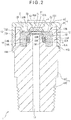
Fig. 2 is a cross section of the physical quantity measuring device according to the exemplary embodiment. -
Fig. 3 is an exploded perspective view showing how a sensor module and a joint are assembled. - Exemplary embodiment(s) of the invention will be described below with reference to the attached drawings.
- An overall structure of a physical quantity measuring device according to the exemplary embodiment is shown in
Figs. 1 to 3 . - As shown in
Figs. 1 to 3 , the physical quantity measuring device includes: ajoint 1; asensor module 2 provided on thejoint 1; anelectronic circuit 3 provided on thesensor module 2; adeformation prevention member 4 covering thesensor module 2; and anelectrical connector 5 connected with theelectronic circuit 3. The physical quantity measuring device of this exemplary embodiment is a pressure detector configured to detect pressure of fluid to be measured. - The
joint 1 is made of a synthetic resin. Thejoint 1 includes ajoint body 11 attached to a target member (not shown) and an elasticallydeformable claw 12 provided to thejoint body 11. - A
pressure inlet 13 for delivering the fluid to be measured to thesensor module 2 is provided inside thejoint body 11 along a central axis thereof. - A
male screw 14 to be meshed with the target member is provided on an outer circumferential portion of a first end of thejoint body 11. Apolygonal portion 15 used for screwing themale screw 14 is provided on an outer circumferential portion of a second end of thejoint body 11. It should be noted that it is not necessary that themale screw 14 is provided on thejoint body 11 but, for instance, thejoint body 11 may have an attachment structure including a flange, which is inserted into a hole in the target portion to serve as an axial seal to keep thejoint body 11 being attached to the target member. - The
joint body 11 includes a projectingportion 16 projecting from anend face 11A on the second end of thejoint body 11. The projectingportion 16 includes: a large-diameter portion 16A formed on theend face 11A; and a small-diameter portion 16B formed on the large-diameter portion 16A. Thepressure inlet 13 opens at the small-diameter portion 16B. - A
step 11B is provided on an outer periphery of theend face 11A of thejoint body 11. - A
flat surface 16C in a plane extending in a radial direction of thejoint body 11 is defined at a border between the large-diameter portion 16A and the small-diameter portion 16B. - The
claw 12 holds an outer periphery of thesensor module 2 and includes twoclaws 12 facing each other across a central axis of thesensor module 2. - Each of the
claws 12 includes arise portion 12A in a form of a rectangular column whose inner face opposes an outer face of thesensor module 2 and ahook 12B defined at an end of therise portion 12A and extended toward the central axis of thesensor module 2. - An angle α defined by the inner face of the
rise portion 12A and a face of thehook 12B facing thesensor module 2 is 90 degrees in the figure. Aslant surface 12C serving as a guide face when thesensor module 2 is attached to thejoint body 11 is formed on a face of thehook 12B opposite the face facing thesensor module 2. It should be noted that the configuration of each of theclaws 12 is not limited to that shown in the drawings as long as each of theclaws 12 is adapted to prohibit thesensor module 2 from being upwardly detached. For instance, the angle α is not necessarily 90 degrees. - The
sensor module 2 includes aceramic module body 20, adetector 23 configured to detect a displacement of thediaphragm 21 and a pad (not shown) electrically connected to thedetector 23. An O ring (not shown) is provided between themodule body 20 and thejoint body 11. - The
module body 20 includes thediaphragm 21 and acylindrical portion 22 integrally provided on a periphery of thediaphragm 21. - The
diaphragm 21 is a thin disc-shaped member configured to be displaced in accordance with the pressure of the fluid to be measured delivered through thejoint body 11. - A
flat surface 21A, on which thedetector 23 is provided, is defined on a first surface of thediaphragm 21 opposite a second surface of thediaphragm 21 with which the fluid to be measured to is in contact. Thedetector 23 includes a strain gauge and an electrically conductive pattern (both not shown). - Locking
grooves 220 for locking each of theclaws 12 is provided on the outer circumferential portion of thecylindrical portion 22 in parallel to the axial direction of thecylindrical portion 22. - Each of the locking
grooves 220 includes a first opposingface 220A facing the inner face of therise portion 12A of each of theclaws 12 and second opposing faces 220B orthogonally provided on both ends of the first opposingface 220A and each facing a lateral face of therise portion 12A, thereby defining a C-shape in a plan view. - A large-
diameter portion 22A in communication with an opening of thecylindrical portion 22 and a small-diameter portion 22B continuous with the large-diameter portion 22A are provided on an inner circumferential portion of thecylindrical portion 22. Aflat surface 22C in a plane extending in a radial direction of thecylindrical portion 22 is defined at a border between the large-diameter portion 22A and the small-diameter portion 22B. - An
O ring 6 is disposed between theflat surface 16C and theflat surface 22C. TheO ring 6 is suitably shaped so that the flow of the fluid to be measured is sealed by the O-ring 6. - The
electronic circuit 3 includes asignal processing circuit 31 and ancircuit parts 32. Thesignal processing circuit 31 includes a plate-shapedcircuit body 31A, andlegs 31B connected to mutually opposite lateral faces of thecircuit body 31A. Thecircuit body 31A is spaced apart from thediaphragm 21 on which thedetector 23 is disposed. Thelegs 31B are connected to a flat surface of thecylindrical portion 22. - The
electrical connector 5 is disposed on thediaphragm 21 of thesensor module 2. Theelectrical connector 5 includes: a terminal 51 electrically connected with thesignal processing circuit 31 and thecircuit parts 32; and aterminal holder 52 that holds the terminal 51. The pad of thesensor module 2, theelectronic circuit 3 and theelectrical connector 5 are connected through an electric circuit, whereby an output signal detected by thedetector 23 is outputted from theelectrical connector 5 to an external device (not shown). - The
terminal holder 52 is a synthetic resin component in a form of a rectangular parallelepiped. Theterminal holder 52 is provided with anotch 52A for upwardly exposing the terminal 51 to allow the terminal 51 to be fitted and connected with a mating connector. - The
deformation prevention member 4 is a cap-shaped component including: acylindrical portion 41 disposed at an outside of each of theclaws 12; and aplate portion 42 whose outer periphery is integrated with thecylindrical portion 41. The material of thedeformation prevention member 4 is not specifically limited but may be made of metal, synthetic resin and the like. - The
cylindrical portion 41 is configured to prevent the deformation of each of theclaws 12 in a direction away from thesensor module 2 and to press therise portion 12A of each of theclaws 12 toward thesensor module 2 by the inner circumferential portion thereof. - The inner circumferential portion of the
cylindrical portion 41 has a circular profile. The outer face of therise portion 12A in the form of rectangular column is in contact with the inner circumferential portion of thecylindrical portion 41. It should be noted that, in order to enlarge the contact area of the inner circumferential portion of thecylindrical portion 41 and the outer face of therise portion 12A, the profile of the outer portion of therise portion 12A may be configured in a form of an arc to conform to the inner circumferential portion of thecylindrical portion 41 in this exemplary embodiment. Further, in this exemplary embodiment, an axially extending groove may be formed on the inner circumferential portion of thecylindrical portion 41 and the outer face of therise portion 12A may be fitted in the groove. - An open end of the
cylindrical portion 41 is provided with astep 41A engaged with thestep 11B on theend face 11A of thejoint body 11. - The
plate portion 42 is a disc-shaped component and is provided at a part thereof with anopening 42A for exposing theelectrical connector 5 to an outside. Theopening 42A is in a form of a rectangle in a plan view to conform to the shape of theelectrical connector 5. - An assembly process of the physical quantity measuring device in this exemplary embodiment will be described below.
- Initially, the
electronic circuit 3 and theelectrical connector 5 are attached to thesensor module 2 in advance, and the O-ring 6 is coaxially attached to the small-diameter portion 16B. Then, thesensor module 2 is attached to the joint body 11 (seeFig. 3 ). - At the time of the attachment, after the position of an end of each of the locking
grooves 220 of thesensor module 2 and the position of each of theclaws 12 of the joint 1 are aligned, thesensor module 2 is pressed toward thejoint body 11 of the joint 1 while keeping the position of the end of each of the lockinggrooves 220 and the position of each of theclaws 12 to be aligned. - At this time, since each of the
claws 12 is provided with theslant surface 12C, each of the lockinggrooves 220 of thesensor module 2 is guided along theslant surface 12C and the end of therise portions 12A is elastically deformed outward. Then, the end of thehook 12B moves while being in contact with each of the lockinggrooves 220 and, when thecylindrical portion 22 of thesensor module 2 is in contact with theend face 11A of thejoint body 11, each of therise portions 12A is brought into contact with each of the lockinggrooves 220 all over the longitudinal length thereof by virtue of the elastic restoration force of therise portions 12A, so that thehooks 12B are positioned on the flat surface of thecylindrical portion 22 of thesensor module 2. Thus, thesensor module 2 is held by theclaws 12. - Subsequently, the
sensor module 2 is covered with thedeformation prevention member 4. At this time, theelectrical connector 5 is inserted into theopening 42A provided on theplate portion 42 of thedeformation prevention member 4. The electronic device (not shown) is connected through a cable to theelectrical connector 5 exposed to an outside through theopening 42A. - The above-described exemplary embodiment provides the following advantages.
- (1) The synthetic resin joint 1 attached with the
sensor module 2 includes thejoint body 11 attached to a target member and the elasticallydeformable claws 12 provided on thejoint body 11 and engaged with thesensor module 2. Since theclaws 12 keep thesensor module 2 to be held by virtue of the elastic force thereof, an additional attachment process (e.g. welding) for attaching thesensor module 2 to the joint 1 is unnecessary. Further, since thejoint body 11 and theclaws 12 are integrally made of a synthetic resin, it is not necessary to separately manufacture thejoint body 11 and theclaws 12. - (2) Since the
deformation prevention member 4 for preventing the deformation of theclaws 12 in a direction away from thesensor module 2 is provided outside theclaws 12, enlargement of the distance between theclaws 12 holding thesensor module 2 and subsequent detachment of thesensor module 2 can be prevented. - (3) The
deformation prevention member 4 includes theplate portion 42 and thecylindrical portion 41 integrated with the outer periphery of theplate portion 42, and presses theclaws 12 with the inner circumferential portion of thecylindrical portion 41. Since thecylindrical portion 41 prevents the deformation of theclaws 12 in the direction away from thesensor module 2, thesensor module 2 can be reliably held by theclaws 12. In addition, since thedeformation prevention member 4 is provided with theplate portion 42 integrated with thecylindrical portion 41, not only the strength of thedeformation prevention member 4 increases, but, since thesensor module 2 is covered with theplate portion 42, dust and the like can be kept from being entered. - (4) Since the
claw 12 includes the twoclaws 12 disposed at mutually opposite positions, thesensor module 2 can be reliably pressed at the two positions. In addition, the production of the joint 1 can be facilitated. For instance, when the joint 1 is manufactured through an injection molding process, though each of theclaws 12 is a component of a complicated shape including thehook 12B, the structure of the injection molding die can be simplified because the joint 1 is axis-symmetrical with respect to a line passing through the twoclaws 12 and the projectingportion 16. - (5) Since each of the
claws 12 includes therise portion 12A provided on thejoint body 11 and thehook 12B provided at an end of therise portion 12A and extended toward the central axis of thesensor module 2, the radial movement as well as the axial movement of thesensor module 2 with respect to thejoint body 11 can be restricted. - (6) Since a part of the
electrical connector 5 disposed on thesensor module 2 is exposed through the opening of thedeformation prevention member 4, theelectrical connector 5 can be easily connected to a control device provided at an outside. - (7) Since the
sensor module 2 is provided with the lockinggrooves 220 with which theclaws 12 are engaged, a circumferential movement of thesensor module 2 is prohibited. - Incidentally, it should be understood that the scope of the present invention is not limited to the above-described exemplary embodiment(s) but includes modifications and improvements as long as the modifications and improvements are compatible with the invention.
- For instance, though the
deformation prevention member 4 in the above-described exemplary embodiment includes thecylindrical portion 41 and theplate portion 42, as long as theclaws 12 can be pressed by the inner circumferential portion of thecylindrical portion 41, the structure of thedeformation prevention member 4 is not specifically limited. For instance, theplate portion 42 may be omitted and thedeformation prevention member 4 may include only thecylindrical portion 41. The shape of the inner circumference of thecylindrical portion 41 may be an ellipse or a rectangle. In the invention, when theclaws 12 have sufficiently large strength, thedeformation prevention member 4 per se is not necessary. - Though each of the
claws 12 includes therise portion 12A provided on thejoint body 11 and thehook 12B integrally formed at an end of therise portion 12A, thehook 12B may be omitted in the invention. Thehook 12B can be omitted by devising a mechanism for increasing a friction resistance between therise portion 12A and the sensor module 2 (e.g. providing a rubber sheet between therise portion 12A and the sensor module 2). When thehook 12B is provided, the shape of thehook 12B is not limited to the shape described in the above exemplary embodiment, For instance, thehook 12B may have an arrowhead end or a spherical end. In the invention, the hook 2B may be formed by: lengthening therise portion 12A; pressing thesensor module 2 against thejoint body 11 of the joint 1 with therise portion 12A being guided along the lockinggroove 220; and bending an end of therise portion 12A toward the center of thesensor module 2. In order to bend the end of therise portion 12A, various methods can be taken. For instance, the end of therise portion 12A may be heated to be deformed, or may be deformed using ultrasonic vibrations. - Though the number of the
claws 12 is two in the above-described exemplary embodiment, the number of theclaws 12 is not limited to two, but only oneclaw 12 or three ormore claws 12 may be provided. When three ormore claws 12 are provided, it is preferable that mutually adjacent ones of the claws are equally spaced. - Though the
sensor module 2 in the above-described embodiment includes thediaphragm 21 and thecylindrical portion 22, the structure of thesensor module 2 in the invention is not limited to that in the above exemplary embodiment, but, for instance, the sensor module may include a board, a diaphragm opposed to a side of the board and a detector provided to the diaphragm and the board to detect the displacement of the diaphragm. In this arrangement, a joint body may be provided without providing the projectingportion 16 to thejoint body 11 and the sensor module may be face-sealed with respect to the joint body using an O-ring. Theelectrical connector 5 is connected to a circuit component necessary for outputting the signal outputted from the detector of the sensor module to an outside. - Even when the diaphragm and the cylindrical portion are provided, it is not necessary that the diaphragm and the cylindrical portion are ceramic components in the invention but the diaphragm and the cylindrical portion may be metal components.
- Further, the physical quantity measuring device of the invention is not limited to be used for pressure measurement as in the exemplary embodiment, but the physical quantity measuring device may be used for measuring differential pressure and the like.
- As described above, the invention encompasses any specific arrangement where a claw component integrated with a joint is configured to hold a sensor module.
Claims (5)
- A physical quantity measuring device comprising:a sensor module (2) comprising a diaphragm (21) provided with a detector (23) configured to detect a pressure of a fluid to be measured; anda joint (1) on which the sensor module (2) is attached, the joint comprising a pressure inlet (13) configured to deliver the fluid to be measured to the sensor module (2),characterized in thatthe joint (1) is made of a synthetic resin and comprises: a joint body (11) attachable to a target member, and an elastically deformable claw (12) provided to the joint body (11) and configured to lock the sensor module (2).
- The physical quantity measuring device according to claim 1, wherein
a deformation prevention member (4) surrounding an outside of the claw (12), the deformation prevention member (4) being configured to prevent a deformation of the claw (12) in a direction away from the sensor module (2). - The physical quantity measuring device according to claim 2, wherein
the claw (12) holds an outer periphery of the sensor module (2), and
the deformation prevention member (4) comprises a plate portion (42) and a cylindrical portion (41) integrally provided on an outer periphery of the plate portion (42), the claw (12) being configured to be pressed by an inner circumferential portion of the cylindrical portion (41). - The physical quantity measuring device according to claim 3, wherein
the sensor module (2) is provided with an electrical connector (5), and
an opening (42A) that is configured to expose the electrical connector (5) to an outside is provided to the deformation prevention member (4). - The physical quantity measuring device according to claim 4, wherein
the sensor module (2) is provided with a locking groove (220) configured to lock the claw (12).
Applications Claiming Priority (1)
| Application Number | Priority Date | Filing Date | Title |
|---|---|---|---|
| JP2015235138A JP6412851B2 (en) | 2015-12-01 | 2015-12-01 | Physical quantity measuring device |
Publications (2)
| Publication Number | Publication Date |
|---|---|
| EP3176559A1 EP3176559A1 (en) | 2017-06-07 |
| EP3176559B1 true EP3176559B1 (en) | 2018-10-03 |
Family
ID=57442583
Family Applications (1)
| Application Number | Title | Priority Date | Filing Date |
|---|---|---|---|
| EP16201487.2A Active EP3176559B1 (en) | 2015-12-01 | 2016-11-30 | Pressure sensor |
Country Status (4)
| Country | Link |
|---|---|
| US (1) | US10145749B2 (en) |
| EP (1) | EP3176559B1 (en) |
| JP (1) | JP6412851B2 (en) |
| CN (1) | CN107014557B (en) |
Families Citing this family (9)
| Publication number | Priority date | Publication date | Assignee | Title |
|---|---|---|---|---|
| JP6235548B2 (en) * | 2015-12-02 | 2017-11-22 | 第一環境株式会社 | Water leakage monitoring device |
| JP6480375B2 (en) * | 2016-04-07 | 2019-03-06 | 長野計器株式会社 | Pressure sensor |
| JP6483050B2 (en) * | 2016-06-02 | 2019-03-13 | 長野計器株式会社 | Physical quantity measuring device |
| JP2018163074A (en) * | 2017-03-27 | 2018-10-18 | 日本電産トーソク株式会社 | Hydraulic sensor mounting structure |
| CN108106756A (en) * | 2017-12-27 | 2018-06-01 | 苏州康姆普机械有限公司 | A kind of detachable pressure sensor |
| CN107907248A (en) * | 2017-12-27 | 2018-04-13 | 苏州康姆普机械有限公司 | A kind of pressure sensor being stably connected with |
| CN108548630B (en) * | 2018-04-05 | 2020-06-26 | 宁波依诺汽车电子有限公司 | Automobile pressure sensor |
| JP6964063B2 (en) * | 2018-11-28 | 2021-11-10 | 長野計器株式会社 | Sensor assembly and physical quantity measuring device |
| JP7005550B2 (en) | 2019-03-29 | 2022-01-21 | 長野計器株式会社 | Manufacturing method of physical quantity measuring device and physical quantity measuring device |
Family Cites Families (15)
| Publication number | Priority date | Publication date | Assignee | Title |
|---|---|---|---|---|
| US5351550A (en) * | 1992-10-16 | 1994-10-04 | Honeywell Inc. | Pressure sensor adapted for use with a component carrier |
| US6584851B2 (en) * | 2000-11-30 | 2003-07-01 | Nagano Keiki Co., Ltd. | Fluid pressure sensor having a pressure port |
| JP4635391B2 (en) * | 2001-08-02 | 2011-02-23 | 株式会社デンソー | Pressure sensor mounting structure |
| US20030056100A1 (en) * | 2001-09-14 | 2003-03-20 | Rodney Beatson | Method and system for authenticating a digitized signature for execution of an electronic document |
| US6604429B1 (en) * | 2002-02-11 | 2003-08-12 | Delphi Technologies, Inc. | Insert-molded pressure sensor with high pressure stainless steel sensing element |
| US6619129B2 (en) * | 2002-02-15 | 2003-09-16 | Delphi Technologies, Inc. | Three-piece pressure sensor with high pressure stainless steel sensing element |
| JP2004325210A (en) | 2003-04-24 | 2004-11-18 | Noritz Corp | Mounting structure of sensor |
| JP2005214843A (en) | 2004-01-30 | 2005-08-11 | Toshiba Corp | Water meter with leaked water detection function |
| JP4963069B2 (en) * | 2007-02-20 | 2012-06-27 | 株式会社鷺宮製作所 | Pressure sensor |
| US8028584B2 (en) | 2007-08-20 | 2011-10-04 | Denso Corporation | Pressure sensor and method for manufacturing the same |
| CN102985801B (en) | 2010-07-13 | 2015-02-25 | 三菱电机株式会社 | Pressure sensor unit and brake device |
| WO2014145674A1 (en) * | 2013-03-15 | 2014-09-18 | Measurement Ltd. | Low profile pressure sensor |
| JP6111766B2 (en) * | 2013-03-19 | 2017-04-12 | 株式会社デンソー | Pressure sensor mounting structure and mounting method |
| JP5852609B2 (en) * | 2013-06-10 | 2016-02-03 | 長野計器株式会社 | Sensor |
| DE102013220091A1 (en) * | 2013-10-02 | 2015-04-02 | Kavlico GmbH | pressure sensor |
-
2015
- 2015-12-01 JP JP2015235138A patent/JP6412851B2/en active Active
-
2016
- 2016-11-29 US US15/363,184 patent/US10145749B2/en active Active
- 2016-11-30 CN CN201611081833.0A patent/CN107014557B/en active Active
- 2016-11-30 EP EP16201487.2A patent/EP3176559B1/en active Active
Non-Patent Citations (1)
| Title |
|---|
| None * |
Also Published As
| Publication number | Publication date |
|---|---|
| JP6412851B2 (en) | 2018-10-24 |
| CN107014557B (en) | 2020-06-19 |
| US10145749B2 (en) | 2018-12-04 |
| EP3176559A1 (en) | 2017-06-07 |
| CN107014557A (en) | 2017-08-04 |
| JP2017102011A (en) | 2017-06-08 |
| US20170153157A1 (en) | 2017-06-01 |
Similar Documents
| Publication | Publication Date | Title |
|---|---|---|
| EP3176559B1 (en) | Pressure sensor | |
| EP2889599B1 (en) | Physical quantity measuring sensor and sensor module | |
| KR102366689B1 (en) | Physical quantity measuring device | |
| US9003899B2 (en) | Force sensor | |
| TWI674398B (en) | Physical quantity measuring device and method of manufacturing the same | |
| EP3023759B1 (en) | Pressure sensor | |
| EP3229004B1 (en) | Pressure sensor | |
| US9816890B2 (en) | Pressure sensor with plastically deformable connection | |
| EP2921839A2 (en) | Pressure sensor | |
| EP3457104B1 (en) | Force sensor | |
| TWI663388B (en) | Physical quantity measuring device | |
| JP6608334B2 (en) | Physical quantity measuring device | |
| KR102678706B1 (en) | Pressure sensor unit | |
| KR102408569B1 (en) | Pressure sensor unit | |
| JP5997686B2 (en) | Physical quantity measurement sensor | |
| JP6030539B2 (en) | Sensor module and physical quantity sensor |
Legal Events
| Date | Code | Title | Description |
|---|---|---|---|
| AK | Designated contracting states |
Kind code of ref document: A1 Designated state(s): AL AT BE BG CH CY CZ DE DK EE ES FI FR GB GR HR HU IE IS IT LI LT LU LV MC MK MT NL NO PL PT RO RS SE SI SK SM TR |
|
| AX | Request for extension of the european patent |
Extension state: BA ME |
|
| PUAI | Public reference made under article 153(3) epc to a published international application that has entered the european phase |
Free format text: ORIGINAL CODE: 0009012 |
|
| STAA | Information on the status of an ep patent application or granted ep patent |
Free format text: STATUS: THE APPLICATION HAS BEEN PUBLISHED |
|
| STAA | Information on the status of an ep patent application or granted ep patent |
Free format text: STATUS: REQUEST FOR EXAMINATION WAS MADE |
|
| 17P | Request for examination filed |
Effective date: 20171026 |
|
| RBV | Designated contracting states (corrected) |
Designated state(s): AL AT BE BG CH CY CZ DE DK EE ES FI FR GB GR HR HU IE IS IT LI LT LU LV MC MK MT NL NO PL PT RO RS SE SI SK SM TR |
|
| GRAP | Despatch of communication of intention to grant a patent |
Free format text: ORIGINAL CODE: EPIDOSNIGR1 |
|
| STAA | Information on the status of an ep patent application or granted ep patent |
Free format text: STATUS: GRANT OF PATENT IS INTENDED |
|
| INTG | Intention to grant announced |
Effective date: 20180425 |
|
| GRAS | Grant fee paid |
Free format text: ORIGINAL CODE: EPIDOSNIGR3 |
|
| GRAA | (expected) grant |
Free format text: ORIGINAL CODE: 0009210 |
|
| STAA | Information on the status of an ep patent application or granted ep patent |
Free format text: STATUS: THE PATENT HAS BEEN GRANTED |
|
| AK | Designated contracting states |
Kind code of ref document: B1 Designated state(s): AL AT BE BG CH CY CZ DE DK EE ES FI FR GB GR HR HU IE IS IT LI LT LU LV MC MK MT NL NO PL PT RO RS SE SI SK SM TR |
|
| REG | Reference to a national code |
Ref country code: GB Ref legal event code: FG4D |
|
| REG | Reference to a national code |
Ref country code: CH Ref legal event code: EP Ref country code: AT Ref legal event code: REF Ref document number: 1049115 Country of ref document: AT Kind code of ref document: T Effective date: 20181015 |
|
| REG | Reference to a national code |
Ref country code: IE Ref legal event code: FG4D Ref country code: DE Ref legal event code: R096 Ref document number: 602016006212 Country of ref document: DE |
|
| REG | Reference to a national code |
Ref country code: NL Ref legal event code: MP Effective date: 20181003 |
|
| REG | Reference to a national code |
Ref country code: LT Ref legal event code: MG4D |
|
| REG | Reference to a national code |
Ref country code: AT Ref legal event code: MK05 Ref document number: 1049115 Country of ref document: AT Kind code of ref document: T Effective date: 20181003 |
|
| PG25 | Lapsed in a contracting state [announced via postgrant information from national office to epo] |
Ref country code: NL Free format text: LAPSE BECAUSE OF FAILURE TO SUBMIT A TRANSLATION OF THE DESCRIPTION OR TO PAY THE FEE WITHIN THE PRESCRIBED TIME-LIMIT Effective date: 20181003 |
|
| PG25 | Lapsed in a contracting state [announced via postgrant information from national office to epo] |
Ref country code: PL Free format text: LAPSE BECAUSE OF FAILURE TO SUBMIT A TRANSLATION OF THE DESCRIPTION OR TO PAY THE FEE WITHIN THE PRESCRIBED TIME-LIMIT Effective date: 20181003 Ref country code: AT Free format text: LAPSE BECAUSE OF FAILURE TO SUBMIT A TRANSLATION OF THE DESCRIPTION OR TO PAY THE FEE WITHIN THE PRESCRIBED TIME-LIMIT Effective date: 20181003 Ref country code: LT Free format text: LAPSE BECAUSE OF FAILURE TO SUBMIT A TRANSLATION OF THE DESCRIPTION OR TO PAY THE FEE WITHIN THE PRESCRIBED TIME-LIMIT Effective date: 20181003 Ref country code: HR Free format text: LAPSE BECAUSE OF FAILURE TO SUBMIT A TRANSLATION OF THE DESCRIPTION OR TO PAY THE FEE WITHIN THE PRESCRIBED TIME-LIMIT Effective date: 20181003 Ref country code: LV Free format text: LAPSE BECAUSE OF FAILURE TO SUBMIT A TRANSLATION OF THE DESCRIPTION OR TO PAY THE FEE WITHIN THE PRESCRIBED TIME-LIMIT Effective date: 20181003 Ref country code: NO Free format text: LAPSE BECAUSE OF FAILURE TO SUBMIT A TRANSLATION OF THE DESCRIPTION OR TO PAY THE FEE WITHIN THE PRESCRIBED TIME-LIMIT Effective date: 20190103 Ref country code: IS Free format text: LAPSE BECAUSE OF FAILURE TO SUBMIT A TRANSLATION OF THE DESCRIPTION OR TO PAY THE FEE WITHIN THE PRESCRIBED TIME-LIMIT Effective date: 20190203 Ref country code: BG Free format text: LAPSE BECAUSE OF FAILURE TO SUBMIT A TRANSLATION OF THE DESCRIPTION OR TO PAY THE FEE WITHIN THE PRESCRIBED TIME-LIMIT Effective date: 20190103 Ref country code: CZ Free format text: LAPSE BECAUSE OF FAILURE TO SUBMIT A TRANSLATION OF THE DESCRIPTION OR TO PAY THE FEE WITHIN THE PRESCRIBED TIME-LIMIT Effective date: 20181003 Ref country code: FI Free format text: LAPSE BECAUSE OF FAILURE TO SUBMIT A TRANSLATION OF THE DESCRIPTION OR TO PAY THE FEE WITHIN THE PRESCRIBED TIME-LIMIT Effective date: 20181003 |
|
| PG25 | Lapsed in a contracting state [announced via postgrant information from national office to epo] |
Ref country code: GR Free format text: LAPSE BECAUSE OF FAILURE TO SUBMIT A TRANSLATION OF THE DESCRIPTION OR TO PAY THE FEE WITHIN THE PRESCRIBED TIME-LIMIT Effective date: 20190104 Ref country code: RS Free format text: LAPSE BECAUSE OF FAILURE TO SUBMIT A TRANSLATION OF THE DESCRIPTION OR TO PAY THE FEE WITHIN THE PRESCRIBED TIME-LIMIT Effective date: 20181003 Ref country code: AL Free format text: LAPSE BECAUSE OF FAILURE TO SUBMIT A TRANSLATION OF THE DESCRIPTION OR TO PAY THE FEE WITHIN THE PRESCRIBED TIME-LIMIT Effective date: 20181003 Ref country code: PT Free format text: LAPSE BECAUSE OF FAILURE TO SUBMIT A TRANSLATION OF THE DESCRIPTION OR TO PAY THE FEE WITHIN THE PRESCRIBED TIME-LIMIT Effective date: 20190203 Ref country code: SE Free format text: LAPSE BECAUSE OF FAILURE TO SUBMIT A TRANSLATION OF THE DESCRIPTION OR TO PAY THE FEE WITHIN THE PRESCRIBED TIME-LIMIT Effective date: 20181003 |
|
| REG | Reference to a national code |
Ref country code: DE Ref legal event code: R097 Ref document number: 602016006212 Country of ref document: DE |
|
| PG25 | Lapsed in a contracting state [announced via postgrant information from national office to epo] |
Ref country code: IT Free format text: LAPSE BECAUSE OF FAILURE TO SUBMIT A TRANSLATION OF THE DESCRIPTION OR TO PAY THE FEE WITHIN THE PRESCRIBED TIME-LIMIT Effective date: 20181003 Ref country code: DK Free format text: LAPSE BECAUSE OF FAILURE TO SUBMIT A TRANSLATION OF THE DESCRIPTION OR TO PAY THE FEE WITHIN THE PRESCRIBED TIME-LIMIT Effective date: 20181003 Ref country code: ES Free format text: LAPSE BECAUSE OF FAILURE TO SUBMIT A TRANSLATION OF THE DESCRIPTION OR TO PAY THE FEE WITHIN THE PRESCRIBED TIME-LIMIT Effective date: 20181003 Ref country code: LU Free format text: LAPSE BECAUSE OF NON-PAYMENT OF DUE FEES Effective date: 20181130 |
|
| PLBE | No opposition filed within time limit |
Free format text: ORIGINAL CODE: 0009261 |
|
| STAA | Information on the status of an ep patent application or granted ep patent |
Free format text: STATUS: NO OPPOSITION FILED WITHIN TIME LIMIT |
|
| REG | Reference to a national code |
Ref country code: BE Ref legal event code: MM Effective date: 20181130 |
|
| REG | Reference to a national code |
Ref country code: IE Ref legal event code: MM4A |
|
| PG25 | Lapsed in a contracting state [announced via postgrant information from national office to epo] |
Ref country code: MC Free format text: LAPSE BECAUSE OF FAILURE TO SUBMIT A TRANSLATION OF THE DESCRIPTION OR TO PAY THE FEE WITHIN THE PRESCRIBED TIME-LIMIT Effective date: 20181003 Ref country code: RO Free format text: LAPSE BECAUSE OF FAILURE TO SUBMIT A TRANSLATION OF THE DESCRIPTION OR TO PAY THE FEE WITHIN THE PRESCRIBED TIME-LIMIT Effective date: 20181003 Ref country code: SK Free format text: LAPSE BECAUSE OF FAILURE TO SUBMIT A TRANSLATION OF THE DESCRIPTION OR TO PAY THE FEE WITHIN THE PRESCRIBED TIME-LIMIT Effective date: 20181003 Ref country code: SM Free format text: LAPSE BECAUSE OF FAILURE TO SUBMIT A TRANSLATION OF THE DESCRIPTION OR TO PAY THE FEE WITHIN THE PRESCRIBED TIME-LIMIT Effective date: 20181003 Ref country code: EE Free format text: LAPSE BECAUSE OF FAILURE TO SUBMIT A TRANSLATION OF THE DESCRIPTION OR TO PAY THE FEE WITHIN THE PRESCRIBED TIME-LIMIT Effective date: 20181003 |
|
| 26N | No opposition filed |
Effective date: 20190704 |
|
| PG25 | Lapsed in a contracting state [announced via postgrant information from national office to epo] |
Ref country code: SI Free format text: LAPSE BECAUSE OF FAILURE TO SUBMIT A TRANSLATION OF THE DESCRIPTION OR TO PAY THE FEE WITHIN THE PRESCRIBED TIME-LIMIT Effective date: 20181003 Ref country code: IE Free format text: LAPSE BECAUSE OF NON-PAYMENT OF DUE FEES Effective date: 20181130 |
|
| PG25 | Lapsed in a contracting state [announced via postgrant information from national office to epo] |
Ref country code: BE Free format text: LAPSE BECAUSE OF NON-PAYMENT OF DUE FEES Effective date: 20181130 |
|
| PG25 | Lapsed in a contracting state [announced via postgrant information from national office to epo] |
Ref country code: MT Free format text: LAPSE BECAUSE OF NON-PAYMENT OF DUE FEES Effective date: 20181130 |
|
| PG25 | Lapsed in a contracting state [announced via postgrant information from national office to epo] |
Ref country code: TR Free format text: LAPSE BECAUSE OF FAILURE TO SUBMIT A TRANSLATION OF THE DESCRIPTION OR TO PAY THE FEE WITHIN THE PRESCRIBED TIME-LIMIT Effective date: 20181003 |
|
| PG25 | Lapsed in a contracting state [announced via postgrant information from national office to epo] |
Ref country code: CY Free format text: LAPSE BECAUSE OF FAILURE TO SUBMIT A TRANSLATION OF THE DESCRIPTION OR TO PAY THE FEE WITHIN THE PRESCRIBED TIME-LIMIT Effective date: 20181003 Ref country code: HU Free format text: LAPSE BECAUSE OF FAILURE TO SUBMIT A TRANSLATION OF THE DESCRIPTION OR TO PAY THE FEE WITHIN THE PRESCRIBED TIME-LIMIT; INVALID AB INITIO Effective date: 20161130 Ref country code: MK Free format text: LAPSE BECAUSE OF NON-PAYMENT OF DUE FEES Effective date: 20181003 |
|
| REG | Reference to a national code |
Ref country code: CH Ref legal event code: PL |
|
| PG25 | Lapsed in a contracting state [announced via postgrant information from national office to epo] |
Ref country code: LI Free format text: LAPSE BECAUSE OF NON-PAYMENT OF DUE FEES Effective date: 20191130 Ref country code: CH Free format text: LAPSE BECAUSE OF NON-PAYMENT OF DUE FEES Effective date: 20191130 |
|
| PGFP | Annual fee paid to national office [announced via postgrant information from national office to epo] |
Ref country code: GB Payment date: 20231003 Year of fee payment: 8 |
|
| PGFP | Annual fee paid to national office [announced via postgrant information from national office to epo] |
Ref country code: FR Payment date: 20231130 Year of fee payment: 8 Ref country code: DE Payment date: 20231016 Year of fee payment: 8 |