EP3514515A1 - Thermocouple and method for manufacturing the thermocouple - Google Patents
Thermocouple and method for manufacturing the thermocouple Download PDFInfo
- Publication number
- EP3514515A1 EP3514515A1 EP18152264.0A EP18152264A EP3514515A1 EP 3514515 A1 EP3514515 A1 EP 3514515A1 EP 18152264 A EP18152264 A EP 18152264A EP 3514515 A1 EP3514515 A1 EP 3514515A1
- Authority
- EP
- European Patent Office
- Prior art keywords
- thermocouple
- wire
- section
- layer
- embedded
- Prior art date
- Legal status (The legal status is an assumption and is not a legal conclusion. Google has not performed a legal analysis and makes no representation as to the accuracy of the status listed.)
- Granted
Links
Images



Classifications
-
- G—PHYSICS
- G01—MEASURING; TESTING
- G01K—MEASURING TEMPERATURE; MEASURING QUANTITY OF HEAT; THERMALLY-SENSITIVE ELEMENTS NOT OTHERWISE PROVIDED FOR
- G01K7/00—Measuring temperature based on the use of electric or magnetic elements directly sensitive to heat ; Power supply therefor, e.g. using thermoelectric elements
- G01K7/02—Measuring temperature based on the use of electric or magnetic elements directly sensitive to heat ; Power supply therefor, e.g. using thermoelectric elements using thermoelectric elements, e.g. thermocouples
-
- G—PHYSICS
- G01—MEASURING; TESTING
- G01K—MEASURING TEMPERATURE; MEASURING QUANTITY OF HEAT; THERMALLY-SENSITIVE ELEMENTS NOT OTHERWISE PROVIDED FOR
- G01K7/00—Measuring temperature based on the use of electric or magnetic elements directly sensitive to heat ; Power supply therefor, e.g. using thermoelectric elements
- G01K7/02—Measuring temperature based on the use of electric or magnetic elements directly sensitive to heat ; Power supply therefor, e.g. using thermoelectric elements using thermoelectric elements, e.g. thermocouples
- G01K7/04—Measuring temperature based on the use of electric or magnetic elements directly sensitive to heat ; Power supply therefor, e.g. using thermoelectric elements using thermoelectric elements, e.g. thermocouples the object to be measured not forming one of the thermoelectric materials
-
- C—CHEMISTRY; METALLURGY
- C23—COATING METALLIC MATERIAL; COATING MATERIAL WITH METALLIC MATERIAL; CHEMICAL SURFACE TREATMENT; DIFFUSION TREATMENT OF METALLIC MATERIAL; COATING BY VACUUM EVAPORATION, BY SPUTTERING, BY ION IMPLANTATION OR BY CHEMICAL VAPOUR DEPOSITION, IN GENERAL; INHIBITING CORROSION OF METALLIC MATERIAL OR INCRUSTATION IN GENERAL
- C23C—COATING METALLIC MATERIAL; COATING MATERIAL WITH METALLIC MATERIAL; SURFACE TREATMENT OF METALLIC MATERIAL BY DIFFUSION INTO THE SURFACE, BY CHEMICAL CONVERSION OR SUBSTITUTION; COATING BY VACUUM EVAPORATION, BY SPUTTERING, BY ION IMPLANTATION OR BY CHEMICAL VAPOUR DEPOSITION, IN GENERAL
- C23C2/00—Hot-dipping or immersion processes for applying the coating material in the molten state without affecting the shape; Apparatus therefor
- C23C2/04—Hot-dipping or immersion processes for applying the coating material in the molten state without affecting the shape; Apparatus therefor characterised by the coating material
-
- G—PHYSICS
- G01—MEASURING; TESTING
- G01K—MEASURING TEMPERATURE; MEASURING QUANTITY OF HEAT; THERMALLY-SENSITIVE ELEMENTS NOT OTHERWISE PROVIDED FOR
- G01K1/00—Details of thermometers not specially adapted for particular types of thermometer
- G01K1/14—Supports; Fastening devices; Arrangements for mounting thermometers in particular locations
- G01K1/143—Supports; Fastening devices; Arrangements for mounting thermometers in particular locations for measuring surface temperatures
-
- H—ELECTRICITY
- H01—ELECTRIC ELEMENTS
- H01M—PROCESSES OR MEANS, e.g. BATTERIES, FOR THE DIRECT CONVERSION OF CHEMICAL ENERGY INTO ELECTRICAL ENERGY
- H01M10/00—Secondary cells; Manufacture thereof
- H01M10/42—Methods or arrangements for servicing or maintenance of secondary cells or secondary half-cells
- H01M10/425—Structural combination with electronic components, e.g. electronic circuits integrated to the outside of the casing
-
- H—ELECTRICITY
- H01—ELECTRIC ELEMENTS
- H01M—PROCESSES OR MEANS, e.g. BATTERIES, FOR THE DIRECT CONVERSION OF CHEMICAL ENERGY INTO ELECTRICAL ENERGY
- H01M10/00—Secondary cells; Manufacture thereof
- H01M10/42—Methods or arrangements for servicing or maintenance of secondary cells or secondary half-cells
- H01M10/48—Accumulators combined with arrangements for measuring, testing or indicating the condition of cells, e.g. the level or density of the electrolyte
- H01M10/482—Accumulators combined with arrangements for measuring, testing or indicating the condition of cells, e.g. the level or density of the electrolyte for several batteries or cells simultaneously or sequentially
-
- H—ELECTRICITY
- H01—ELECTRIC ELEMENTS
- H01M—PROCESSES OR MEANS, e.g. BATTERIES, FOR THE DIRECT CONVERSION OF CHEMICAL ENERGY INTO ELECTRICAL ENERGY
- H01M10/00—Secondary cells; Manufacture thereof
- H01M10/42—Methods or arrangements for servicing or maintenance of secondary cells or secondary half-cells
- H01M10/48—Accumulators combined with arrangements for measuring, testing or indicating the condition of cells, e.g. the level or density of the electrolyte
- H01M10/486—Accumulators combined with arrangements for measuring, testing or indicating the condition of cells, e.g. the level or density of the electrolyte for measuring temperature
-
- H—ELECTRICITY
- H01—ELECTRIC ELEMENTS
- H01M—PROCESSES OR MEANS, e.g. BATTERIES, FOR THE DIRECT CONVERSION OF CHEMICAL ENERGY INTO ELECTRICAL ENERGY
- H01M10/00—Secondary cells; Manufacture thereof
- H01M10/60—Heating or cooling; Temperature control
- H01M10/65—Means for temperature control structurally associated with the cells
- H01M10/657—Means for temperature control structurally associated with the cells by electric or electromagnetic means
- H01M10/6572—Peltier elements or thermoelectric devices
-
- H—ELECTRICITY
- H01—ELECTRIC ELEMENTS
- H01M—PROCESSES OR MEANS, e.g. BATTERIES, FOR THE DIRECT CONVERSION OF CHEMICAL ENERGY INTO ELECTRICAL ENERGY
- H01M50/00—Constructional details or processes of manufacture of the non-active parts of electrochemical cells other than fuel cells, e.g. hybrid cells
- H01M50/50—Current conducting connections for cells or batteries
- H01M50/502—Interconnectors for connecting terminals of adjacent batteries; Interconnectors for connecting cells outside a battery casing
-
- H—ELECTRICITY
- H01—ELECTRIC ELEMENTS
- H01M—PROCESSES OR MEANS, e.g. BATTERIES, FOR THE DIRECT CONVERSION OF CHEMICAL ENERGY INTO ELECTRICAL ENERGY
- H01M50/00—Constructional details or processes of manufacture of the non-active parts of electrochemical cells other than fuel cells, e.g. hybrid cells
- H01M50/50—Current conducting connections for cells or batteries
- H01M50/502—Interconnectors for connecting terminals of adjacent batteries; Interconnectors for connecting cells outside a battery casing
- H01M50/507—Interconnectors for connecting terminals of adjacent batteries; Interconnectors for connecting cells outside a battery casing comprising an arrangement of two or more busbars within a container structure, e.g. busbar modules
-
- H—ELECTRICITY
- H01—ELECTRIC ELEMENTS
- H01M—PROCESSES OR MEANS, e.g. BATTERIES, FOR THE DIRECT CONVERSION OF CHEMICAL ENERGY INTO ELECTRICAL ENERGY
- H01M50/00—Constructional details or processes of manufacture of the non-active parts of electrochemical cells other than fuel cells, e.g. hybrid cells
- H01M50/50—Current conducting connections for cells or batteries
- H01M50/569—Constructional details of current conducting connections for detecting conditions inside cells or batteries, e.g. details of voltage sensing terminals
-
- H—ELECTRICITY
- H10—SEMICONDUCTOR DEVICES; ELECTRIC SOLID-STATE DEVICES NOT OTHERWISE PROVIDED FOR
- H10N—ELECTRIC SOLID-STATE DEVICES NOT OTHERWISE PROVIDED FOR
- H10N10/00—Thermoelectric devices comprising a junction of dissimilar materials, i.e. devices exhibiting Seebeck or Peltier effects
- H10N10/01—Manufacture or treatment
-
- H—ELECTRICITY
- H10—SEMICONDUCTOR DEVICES; ELECTRIC SOLID-STATE DEVICES NOT OTHERWISE PROVIDED FOR
- H10N—ELECTRIC SOLID-STATE DEVICES NOT OTHERWISE PROVIDED FOR
- H10N10/00—Thermoelectric devices comprising a junction of dissimilar materials, i.e. devices exhibiting Seebeck or Peltier effects
- H10N10/10—Thermoelectric devices comprising a junction of dissimilar materials, i.e. devices exhibiting Seebeck or Peltier effects operating with only the Peltier or Seebeck effects
- H10N10/17—Thermoelectric devices comprising a junction of dissimilar materials, i.e. devices exhibiting Seebeck or Peltier effects operating with only the Peltier or Seebeck effects characterised by the structure or configuration of the cell or thermocouple forming the device
-
- H—ELECTRICITY
- H10—SEMICONDUCTOR DEVICES; ELECTRIC SOLID-STATE DEVICES NOT OTHERWISE PROVIDED FOR
- H10N—ELECTRIC SOLID-STATE DEVICES NOT OTHERWISE PROVIDED FOR
- H10N10/00—Thermoelectric devices comprising a junction of dissimilar materials, i.e. devices exhibiting Seebeck or Peltier effects
- H10N10/80—Constructional details
- H10N10/85—Thermoelectric active materials
- H10N10/856—Thermoelectric active materials comprising organic compositions
-
- H—ELECTRICITY
- H01—ELECTRIC ELEMENTS
- H01M—PROCESSES OR MEANS, e.g. BATTERIES, FOR THE DIRECT CONVERSION OF CHEMICAL ENERGY INTO ELECTRICAL ENERGY
- H01M50/00—Constructional details or processes of manufacture of the non-active parts of electrochemical cells other than fuel cells, e.g. hybrid cells
- H01M50/50—Current conducting connections for cells or batteries
- H01M50/502—Interconnectors for connecting terminals of adjacent batteries; Interconnectors for connecting cells outside a battery casing
- H01M50/509—Interconnectors for connecting terminals of adjacent batteries; Interconnectors for connecting cells outside a battery casing characterised by the type of connection, e.g. mixed connections
- H01M50/51—Connection only in series
-
- Y—GENERAL TAGGING OF NEW TECHNOLOGICAL DEVELOPMENTS; GENERAL TAGGING OF CROSS-SECTIONAL TECHNOLOGIES SPANNING OVER SEVERAL SECTIONS OF THE IPC; TECHNICAL SUBJECTS COVERED BY FORMER USPC CROSS-REFERENCE ART COLLECTIONS [XRACs] AND DIGESTS
- Y02—TECHNOLOGIES OR APPLICATIONS FOR MITIGATION OR ADAPTATION AGAINST CLIMATE CHANGE
- Y02E—REDUCTION OF GREENHOUSE GAS [GHG] EMISSIONS, RELATED TO ENERGY GENERATION, TRANSMISSION OR DISTRIBUTION
- Y02E60/00—Enabling technologies; Technologies with a potential or indirect contribution to GHG emissions mitigation
- Y02E60/10—Energy storage using batteries
Definitions
- the present invention relates to a thermocouple, particularly to a modified thermocouple configured for being ball-bonded or wedge-bonded to a target surface by a wire-bonding apparatus.
- the invention further relates to a method for manufacturing such thermocouple and to a method of bonding, particularly ball-bonding or wedge-bonding, such thermocouple to a target surface.
- the invention further relates to the use of a modified bonding tool for bonding the thermocouple of the invention to a target surface as well as to a battery module comprising the thermocouple according to the present invention.
- a rechargeable or secondary battery differs from a primary battery in that it can be repeatedly charged and discharged, while the latter provides only an irreversible conversion of chemical to electrical energy.
- Low-capacity rechargeable batteries are used as power supply for small electronic devices, such as cellular phones, notebook computers and camcorders, while high-capacity rechargeable batteries are used as the power supply for hybrid vehicles and the like.
- rechargeable batteries include an electrode assembly including a positive electrode, a negative electrode, and a separator interposed between the positive and negative electrodes, a case receiving the electrode assembly, and an electrode terminal electrically connected to the electrode assembly.
- An electrolyte solution is injected into the case in order to enable charging and discharging of the battery via an electrochemical reaction of the positive electrode, the negative electrode, and the electrolyte solution.
- the shape of the case e.g. cylindrical or rectangular, depends on the battery's intended purpose.
- Rechargeable batteries may be used as a battery module formed of a plurality of unit battery cells coupled in series and/or in parallel so as to provide a high energy density, e.g. for motor driving of a hybrid vehicle. That is, the battery module is formed by interconnecting the electrode terminals of the plurality of unit battery cells depending on a required amount of power and in order to realize a high-power rechargeable battery, e.g. for an electric vehicle.
- Battery modules can be constructed either in block design or in modular design.
- each battery cell is coupled to a common current collector structure and a common battery management system.
- pluralities of battery cells are connected to form submodules and several submodules are connected to form the battery module.
- Battery management functions may be realized either on module or submodule level and thus interchangeability of the components is improved.
- One or more battery modules are mechanically and electrically integrated, equipped with a thermal management system and set up for communication with electrical consumers in order to form a battery system.
- Battery systems For meeting the dynamic power demands of various electrical consumers connected to the battery system a static control of battery power output and charging is not sufficient. Thus, steady exchange of information between the battery system and the controllers of the electrical consumers is required. This information includes the battery systems actual state of charge (SoC), potential electrical performance, charging ability and internal resistance as well as actual or predicted power demands or surpluses of the consumers. Battery systems usually comprise a battery management system (BMS) for processing this information.
- SoC state of charge
- BMS battery management system
- thermocouple-based temperature sensors One significant parameter related to the state of a battery cell or module is the battery cell (module) temperature. Therefore, temperature sensitive elements (sensors) are provided within the battery module and the signals provided by such sensors are then considered in controlling the battery module and/or in controlling a thermal management system.
- a variety of temperature sensors providing an electronic temperature dependent signal such as e.g. thermistor-based or thermocouple-based temperature sensors, can be used in battery modules.
- Utilized temperature sensors usually comprise a measurement probe that has to be brought into thermal contact with a target surface of a battery cell and/or module. Therefore spring-loaded measurement probes, e.g. for PTC-based sensors, or thermowells, e.g. for thermocouple-based sensors have been used.
- the thermowells-based solutions for thermocouples may lead to slow temperature sensing due to a delayed heat transfer.
- thermocouple The structure of a thermocouple usually depends on the temperature range to be sensed and the environmental conditions the thermocouple is exposed to. In industrial applications often sheathed thermocouple are used, where the wires are embedded in ceramic insulation with a stainless steel or nickel alloy sheath enclosing the ceramic matrix. Sheathed thermocouples can be brought in contact with a target surface by using a thermowells or, if the measuring junction is ungrounded, by welding the sheath material to the target surface. Further, weldable connectors exist for bringing thermocouples in thermal contact with a target surface. Prior art with respect to thermally connecting a thermocouple's measuring junction to a target surface are described in US 4,659,898 , US 3,939,554 , US 5,141,335 , and US 5,141,335 .
- thermocouples usually applied in industrial applications are rather rigid, such that the connections, particularly welding connections, to the target surface are prone to damages and detachment of the target surface. This may have an adverse effect of the thermal measurements obtained by the thermocouple, which are strongly correlated to the quality of the junction's bond to the target.
- a suitable option cold be basic thermocouples as illustrated in Figure 1 that consist mainly of an elastic wire pair with an exposed junction.
- these basic thermocouples had to be soldered by hand to the target surface and their application was thus mainly restricted to science or to prototype construction.
- thermocouple and a bonding method for such improved thermocouple that can be used on an industrial scale and allows for a long-term stable connection to a target surface even under prolonged vibrations and impacts.
- thermocouple for temperature measurements that comprises a first wire of a first metallic material and a second wire of a second metallic material different from the first metallic material.
- the thermocouple comprises a first section and a second section in a lengthwise direction of the thermocouple.
- the first section of the thermocouple is configured to bend elastically, preferably across the whole length of the first section. Further, in the first section, the first and second wire run electrically isolated from each other.
- the first wire and the second wire are connected to each other to form a measuring junction.
- the connection may be a welded connection but other connection types are possible as well, the wires may even be twisted.
- a first layer of a thermally conductive and electrically isolating first material encloses at least a part of the second section.
- the first layer of the first material surrounds (coats) at least the measuring junction, and particularly preferred the first material coats the full second section of the thermocouple.
- a second layer of ultrasonic-weldable second material encloses at least a part of the first layer.
- the second material coats at least the whole embedded measuring junction and is, further preferred, different from the first material.
- thermocouple of the present invention can advantageously be used in a modified wire-bonding apparatus.
- a weld connection between the thermocouple and a target surface can be established via ultrasonic welding the second material to the target surface using the wire-bonding apparatus.
- the first layer of first material electrically isolates the measuring junction from the second material and the target surface.
- standard wire-bonding apparatuses can be used for bonding the thermocouple to the target surface with only minor modifications carried out to a capillary tool of such apparatus and by replacing a wire coil of the apparatus by a magazine for hosting at least one thermocouple.
- thermocouple of the invention in a modified wire-bonding apparatus a well defined thermal contact can be replicable established between the measuring junction and a target surface.
- quality of the thermal contact strongly influences the measurements of the thermocouple, reliable and comparable measurements can be obtained with the thermocouple of the invention that allows for reproducible bonding.
- thermocouple due to the elasticity of the first section, the thermocouple can be loaded into and applied, guided and positioned by the modified wire-bond apparatus without a risk of breaking its wires or damaging a welded connection. Also, after establishing a weld connection via the second material, the free ends of the first end second wire can be welded to respective contact pads via the modified wire-bonding machine as well. Hence, with the thermocouple of the invention a fully automated setup of a thermocouple temperature sensor is achievable.
- a basic elastic thermocouple is provided as the starting point for the thermocouple of the invention.
- the first section comprises an insulated pair of different wires, insulated e.g. with standard plastic cable insulations
- the second section comprises an exposed section of the pair of wires, wherein the wires are connected, e.g. welded, to each other to form a measuring junction.
- Such basic elastic thermocouples are freely available for commercial applications.
- the thermocouple of the present invention is then obtained by coating exclusively the second section of the basic thermocouple with the first material and, subsequently, with the second material.
- the thermocouple of the invention can be manufactured in a cost-effective way, which further benefits the mass production of the thermocouple according to the invention.
- the first and second wire of the thermocouple form one of a nickel-alloy thermocouple (Type E, J, K, M, N, or T), a platinum/rhodium-alloy thermocouple (Type B, R, or S), a tungsten/rhenium-alloy thermocouple (Type C, D, G), a chromel-gold/iron-alloy thermocouple, a noble-metal alloy thermocouple /Type P), a platinum/molybdenum-alloy thermocouple, a iridium/rhodium alloy thermocouples, a pure noble-metal (Au-Pt, Pt-Pd) thermocouple, or a skutterudite thermocouple.
- a suitable thermocouple is preferably chosen in dependence of the temperature range of interest and, with respect to the coating of the first and second material, with respect to material parameters of the first and second material.
- the length of the first section exceeds the length of the second section in a lengthwise direction of the thermocouple.
- the length of the first section is at least 5 times, 10 times, 15 times, 20, or even 25 times the length of the second section.
- a layer thickness of the first layer is between 0,5 mm and 5 mm, preferably between 0.1 mm and 3 mm, and particularly preferred between 0.1 mm and 1 mm. Such preferred layer thickness enables electric insulation of the measuring junction without significantly decreasing thermal conduction between measuring junction and target surface.
- a layer thickness of the second layer is between 50 ⁇ m and 1 mm, preferably between 50 ⁇ m and 500 ⁇ m, and particularly preferred between 100 ⁇ m and 500 ⁇ m.
- Such preferred layer thickness is advantageously sufficient for manufacturing a reliable and replicable weld connection, e.g. a wedge bond or a ball bond, between the measuring junction and the target surface using a modified wire-bonding apparatus.
- the low layer thickness of the second layer further contributes to a cost-effective production process.
- Both of the first wire and the second wire preferably have an overall diameter between 150 ⁇ m and 3.5 mm, preferably between 300 ⁇ m and 2 mm, and particularly preferred between 500 ⁇ m and 1 mm, respectively.
- the thermocouple has an overall diameter between 300 ⁇ m and 14 mm, particularly preferred between 400 ⁇ m and 10 mm, and further preferred between 500 ⁇ m and 3 mm.
- the overall diameter refers to the largest linear extension of cross sections deviating from a circle. Low overall diameters of the wires and of the thermocouple allow for the use of wire-bonding apparatuses that are widely available for commercial applications and with the need for only minimal modifications applied thereto.
- the first material is a plastic material and, particularly preferred, at least one of polyethylene, polyimide, polyamide, polybutylene terephthalate, polypropylene, polyether ether ketone, epoxy resin or polyphenylene sulfide. These materials provide sufficient electric insulation and at the same time satisfactory thermal conductivity. Further, these materials can be provided in a variety of solid states and hence allow for an uncomplicated application process. Polyimide is particularly preferred due to its thermal stability in a wide temperature range and its good thermal conductivity. Further preferred, the first material comprises thermally conductive fillers, such as e.g. graphite, carbon, sapphire, metal, or ceramic particles. According to an alternatively preferred embodiment, the first material is a ceramic compound with a high thermal stability. Particularly preferred the first material is magnesium oxide. The use of a temperature stable ceramic compound as first material allows for applying the second material from a melt.
- the second material comprises an alloy of at least one of gold, copper, and aluminum.
- These materials are standard materials for wire-bonding applications and thus provide high reliability in providing a weld connection by ultrasonic welding using a modified wire-bonding apparatus.
- other materials such as plastic materials, can be principally used, as long as they are ultrasonic weldable and provide sufficient thermal conductivity.
- the second material is adapted, e.g. equal, to the material of a target surface in order to provide an improved substance to substance bond via the weld.
- the first wire and the second wire of the thermocouple have different length.
- the thermocouple has a basic Y-shape with different lengths of the two top legs.
- a measuring junction is provided by connecting a first free end of the first wire and a first free end of the second wire, e.g. via a weld connection.
- thermocouple for temperature measurements, the method comprising at least the steps of:
- the starting point of the method of the invention is providing a basic thermocouple, which can mean either producing such basic thermocouple or obtaining a freely available basic thermocouple that comprises the further features described above.
- the latter is clearly preferred and advantageously allows for an uncomplicated implementation of the method.
- a basic thermocouples comprises or consists of an insulated pair of wires forming a thermocouple, where in a second section of the thermocouple the insulation is removed and the wires are connected to each other and form a measuring junction.
- the basic thermocouple bends elastically at least within the first section, preferably within the whole first section.
- the method of the invention essentially comprises a two-step coating process of the measuring junction with, first, an insulating but thermally conductive material and, second, a ultrasonic weldable material.
- the thermocouple produced in the method of the invention can be advantageously applied using a wire-bonding machine with minor modifications.
- the first material and the second material are applied exclusively to the second section, particularly preferred exclusively to the measuring junction. Hence, material costs and processing time can be reduced.
- the first section at least one of the first wire and the second wire is enclosed by a plastic cable insulation.
- both of the first and second wire are enclosed in a plastic cable insulation and, also preferred, another plastic cable insulation may coat both insulated wires.
- the first material is a plastic material and, particularly preferred, at least one of polyethylene, polyimide, polyamide, polybutylene terephthalate, polypropylene, polyether ether ketone, epoxy resin or polyphenylene sulfide.
- the second section is then preferably embedded in the first layer of the first material by immersing the second section in a melt or solution of the first material.
- the first layer of the first material forms due to evaporating of a solvent or due to solidification of the adhered melt.
- the plastic material is polyimide and also preferred the melt or solution of the first material comprises a thermally conductive filler.
- the thin foil of the second material is preferably provided with a thickness between 50 ⁇ m and 1 mm, particularly preferred between 50 ⁇ m and 500 ⁇ m, and further preferred between 100 ⁇ m and 500 ⁇ m.
- the thin foil is provided with a surface area corresponding at least roughly to the surface area of the second section embedded in the first material.
- the surface area of the thin foil refers to the surface area of a single side of the foil.
- the wrapping of the foil around the embedded second section or measuring junction may be performed by movably holding an edge section of the thin foil and by guiding the tip of the embedded second section or measuring junction towards and into the foil such that the foil lays around the second section. Essentially this might be considered as a microscopic version of a deep drawing process.
- a wrapping tool as utilized in packaging machines of the food industry can be applied to wrap the thin foil around the second section.
- the first material is a ceramic compound with high thermal stability.
- the first material is magnesium oxide.
- the method preferably comprises the steps of inserting a ceramic compound powder, e.g. magnesium oxide powder, and the second section into a mold.
- the ceramic compound powder may have been grounded beforehand to a grain size and grain form that are suitable for allowing to solidify the ceramic compound powder by compactification.
- the ceramic compound powder is compression molded around the second section, preferably by closing the mold and by applying pressure to the ceramic compound powder such that it compacts around the second section of the thermocouple.
- the compacted ceramic compound powder should be form stable at least temporarily after the compression molding in order to allow application of the second layer.
- At least a part of the second section coated by the first layer is then embedded in the second material by immersing at least a part of the coated second section, e.g. the coated embedded measuring junction, in a melt of the second material, preferably in a melt of an alloy of at least one of gold, copper, and aluminum. If the second material solidifies it safely encloses the first material compacted ceramic powder.
- thermocouple to a target surface.
- the target surface is part of at least one battery cell or battery cell casing of a battery module and the bonding method is integrated into a method for manufacturing a battery module.
- the bonding method of the invention comprises the steps of:
- the bonding method of the present invention is advantageously performed with a wire-bonding apparatus at it is commercially available for microelectronic applications, e.g. for providing wire connections between a chip pad and a lead frame.
- a wire-bonding apparatus as utilized in the bonding method of the invention is usually configured for producing a ball-bond and/or a wedge-bond between a wire segment and a target surface.
- the wire-bonding apparatus is configured for producing a ball-bond and/or a wedge bond between a thermocouple of the invention as described above and a target surface.
- the minor modifications refer at least to the replacement of a wire coil with a magazine configured for hosting at least one thermocouple of the invention and the adaption of a capillary tool of the wire-bonding apparatus to the overall diameter of such thermocouple.
- a wire-bonding apparatus is equipped with a thermocouple of the invention as described above by providing a suitable magazine. From such magazine, a single thermocouple is loaded to a capillary tool of the wire-bonding apparatus. The capillary tool is then positioned on a target surface and the thermocouple is guided through the capillary tool such that a tip of the second section, i.e. the embedded measuring junction, is aligned with an opening of the capillary tool. The thermocouple is fixated in the capillary tool and the aligned embedded measuring junction is put on the target surface.
- thermocouple Subsequently downward pressure is exerted onto the fixed thermocouple via the capillary tool and ultrasonic energy is applied to the thermocouple via an ultrasonic transducer.
- the second material coating the second section is ultrasonic welded to the target surface.
- the bonding method of the present invention further comprises the step of at least partially fusing the second material of the aligned embedded second section by applying heat or an electric arc thereto before applying downward pressure and ultrasonic energy to the thermocouple.
- the second material is at least partially melted before putting the embedded measuring junction on the target surface, such that a ball of fused second material forms at the tip of the second section. This ball of fused second material is then put on the target surface to form a ball-bond.
- the capillary tool can be freely moved in any direction after producing the ball-bond and hence alignment of the capillary tool is simplified.
- the second end of the first wire and the second end of the second wire are welded to respective contact pads on a circuit carrier, e.g. on a cell supervision circuit carrier.
- a circuit carrier e.g. on a cell supervision circuit carrier.
- thermocouple with first and second wires of different length as described above is used in this embodiment. Then, if the capillary tool arrives at the position of a first contact pad, preferably the free second end of one of the first and second wire is positioned in the opening of the capillary tool and, if the capillary tool arrives at the position of a second contact pad, the free second end of the other one of the first and second wire is positioned in the opening. Hence, both of the free second ends of the thermocouple wires can be bonded to a respective contact pad via the wire-bonding apparatus with reduced risk of electrically shorting the wires.
- the wire-bonding apparatus is based on a standard wire bonding apparatus that is modified at least in that it comprises a magazine configured for accommodating at least one thermocouple, and a capillary tool configured for loading a thermocouple and for applying downward pressure and ultrasonic energy to the embedded second section of the loaded thermocouple, wherein an inner diameter of the capillary tool is adapted to an outer diameter of the thermocouple.
- thermocouple of the invention As described above by providing a suitable magazine. From there, a single thermocouple can be loaded to a capillary tool of the wire-bonding apparatus.
- the capillary tool comprises a capillary configured for guiding the thermocouple and at least one element configured for fixing the thermocouple in the capillary in order to exert downward pressure onto the thermocouple.
- the wire-bonding apparatus further comprises at least one element configured for guiding a thermocouple from the magazine into and through the capillary, at least one element configured for moving and positioning the capillary tool and at least one ultrasonic transducer.
- the capillary tool further comprises at least one element for exerting heat or an electric arc to the opening region of the capillary tool and a thermocouple positioned therein.
- a battery module comprising a plurality of stacked battery cells that are electrically interconnected in series and/or in parallel between a negative module terminal and a positive module terminal via a plurality of busbars.
- the battery module further comprises a cell supervision circuit, CSC, carrier that is arranged on top of the plurality of stacked battery cells and that comprises at least one first contact pad and at least one second contact pad.
- CSC cell supervision circuit
- the battery module further comprises at least one thermocouple according to the present invention as described above, wherein the second material of the embedded second section of the at least one thermocouple is welded to a top surface of a battery cell, and wherein a free end of the first wire is welded to a first contact pad and a free end of the second wire is welded to a second contact pad.
- the CSC carrier preferably comprises at least one cell supervision circuit that is electrically connected to the first and second contact pads and is configured for receiving and processing signals related to the temperatures detected via the thermocouple and, preferably, voltages of the cells.
- the term “and/or” includes any and all combinations of one or more of the associated listed items. Expressions such as “at least one of,” preceding a list of elements, modify the entire list but not its individual elements. As used herein, the term “substantially,” “about,” and similar terms are used as terms of approximation and not as terms of degree, and are intended to account for the inherent deviations in measured or calculated values that would be recognized by those of ordinary skill in the art. Further, if the term “substantially” is used in combination with a feature that could be expressed using a numeric value, the term “substantially” denotes a range of +/- 5% of the value centered on the value.
- FIG. 1 (A) to (C) shows basic thermocouples 1 according to the prior art that are commercially available particularly for scientific purposes or prototype construction.
- These basic thermocouples comprise a first wire 11 and a second wire 12 that are bead welded to each other to form a measuring junction 13.
- the basic thermocouples 1 are configured to bend elastically, i.e. they are not rigid, preferably across their whole length.
- the basic thermocouples 1 comprise a first section 21, wherein the first 11 and second wire 12 run electrically isolated from each other by being surrounded by at least one plastic cable insulation 14.
- the basic thermocouples 1 further comprise a second section 22, wherein the measuring junction 13 is formed and wherein the wires 11, 12 are exposed, i.e. not insulated.
- Figure 2 (A) to (C) show different stages in a method for producing a thermocouple 10 according to the invention from a basic thermocouple 1.
- Figure 2 (A) shows the basic thermocouple 1 of Figure 1 (B)
- Figure 2 (C) shows a thermocouple 10 of the invention.
- the basic thermocouple 1 of Figure 2 (A) is transformed to a thermocouple of the invention 10 by initially coating the second section 22 of the basic thermocouple 1 with a first layer 31 of a first material 41.
- the first material 41 is thermally conductive and electrically insulating.
- the first layer 31 of first material 41 is partially coated with a second layer 32 of a second material 42 that is ultrasonic weldable to a target surface.
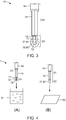
- FIG 3 shows the thermocouple 10 according to the invention of Figure 2 (C) with a cross-sectional cut through the second section 22 of the thermocouple 10.
- the measuring junction 13 is embedded (coated) by a first layer 31 of a first material 41 that is electrically insulating the measuring junction 13 but does not impede heat flux to and from the measuring junction 13.
- the first material 41 might be polyimide and the first layer might have a thickness of 1 mm around the bead-shaped measuring junction 13.
- the first layer 31 is partially embedded (coated) by a second layer 32 of a second material 42. At least the tip, i.e. the embedded measuring junction 13, is coated by the second layer 32 of the second material 42.
- the second material 42 is aluminum and the second layer 32 has a thickness of 100 ⁇ m.
- the thermocouple 10 as illustrated in Figure 3 can be advantageously bonded to a target surface using a wire-bonding apparatus.
- FIG. 4 schematically illustrates a method for producing a thermocouple 10 of the invention.
- a basic thermocouple 1 as described above is provided.
- the second section 22 of the basic thermocouple 1 is immersed in a solution 51 of the first material, particularly in a solution of polyimide in dimethylformamide (DMF), N-methyl pyrrolidon (NMP), or N-ethyl pyrrolidon (NEP) as a solvent.
- a first layer 31 of polyimide as the first material 41 is thus dip coated onto the second section 22 of the basic thermocouple 1. After the solvent has evaporated and the polyimide coating is cured, the method proceeds with a second step (B).
- a thin aluminum foil 52 is provided with a thickness of 100 ⁇ m and a one sided surface area that is essentially equal to 50 % of the surface area of the second section 22 coated in the first material 41.
- the thermocouple 10 is moved such that the second section 22 is driven into the thin foil 52 which thus wraps around the tip of the second section 22 in a manner comparable to deep drawing.
- a thermocouple 10 as illustrated in Figure 3 results from step (B) of Figure 4 .
- heat curing may be applied to intensify the bonding of the second material 42 to the first layer 31 of the first material 41.
- FIG. 5 schematically illustrates another method for producing a thermocouple 10 of the invention.
- a basic thermocouple 1 as described above is provided.
- a grounded magnesium oxide powder 53 is provided into a compression mold 61.
- the magnesium oxide powder 53 is mainly applied to the walls of the mold 61.
- the second section 22 of the basic thermocouple 1 is inserted into the mold 61 such that it is uniformly surrounded by the powder 53 attached to the walls of the mold 61.
- the mold 61 is then closed such that pressure is exerted on the magnesium oxide powder 53.
- the powder 53 is thus compacted and solidified around the second section 22 of the basic thermocouple 1.
- a first layer 31 of magnesium oxide as second material 41 is thus formed around the second section 22.
- thermocouple 10 as illustrated in Figure 3 is produced in the step (B) of Figure 5 .
- FIG. 6 schematically illustrates the bonding of a thermocouple 10 according to an embodiment to a target surface 15 using a modified capillary tool 62.
- a thermocouple 10 of the invention is loaded from a magazine (not shown) of a wire-bonding apparatus (not shown) hosting a plurality of such thermocouples 10 into a capillary tool 62 by at least one element for guiding and transporting the thermocouple 10.
- the capillary tool 62 comprises a capillary wherein the thermocouple is positioned and aligned such that the second section 22 of the thermocouple protrudes from an opening of the capillary tool 62.
- the capillary tool 62 is positioned above a target surface (not shown) at a position predetermined for establishing a weld connection between the thermocouple 10 and the target surface (not shown).
- thermocouple 10 heat is applied to the second section 22 of the thermocouple 10 by applying an electric arc (not shown) to the second section 22.
- This fuses at least parts of the second material 42 of the second layer 32 such that a ball of melted second material 42 forms at the tip of the second section 22.
- thermocouple 10 is fixated in the capillary tool 62 by constricting at least a part of the capillary tool 62.
- the capillary tool 62 with the fixated thermocouple 10 is then lowered onto the target surface 15 as indicated by the downward facing arrows in Figure 6 (C) .
- a downward pressure is exerted onto the second material 42.
- ultrasonic energy is applied to the capillary tool 62 and the thermocouple 10 via an ultrasonic transducer (not shown) as indicated by the arrows facing sideways.
- the at least partially fused second material 42 forms a weld connection with the target surface 15.
- thermocouple 10 of the invention as illustrated in Figure 3 an be produced from a standardized basic thermocouple 1 in a standardized method as schematically illustrated in Figures 4 and 5 and can be bonded to a target surface in a standardized bonding method using a common wire-bonding apparatus as illustrated in Figure 6 .
- the welded mechanical connection between the second material 42 and the target surface 15 is well defined and highly replicable.
- a temperature measurement by the thermocouple 10 can obtain the temperature at the thermal interface of the welding area between the second material 42 and the target surface 15 in a highly reproducible and reliable manner.
- an exemplary embodiment of a battery module 70 includes a plurality of battery cells 71 aligned in one direction.
- Each battery cell 71 is a prismatic (or rectangular) cell, the wide flat surfaces of which are stacked together to form the battery module 70.
- Each battery cell 10 includes a battery case configured for accommodation of an electrode assembly and an electrolyte.
- the battery cells 71 are provided with positive and negative electrode terminals having different polarities.
- the positive and negative electrode terminals of neighboring battery cells 71 are electrically connected through busbars 74 such that a series connection of the battery cells 71 between a negative module terminal 72 and a positive module terminal 73 results.
- module 70 can be used as power source by connecting the plurality of battery cells 71 as one bundle.
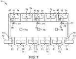
- the battery module 70 and the cell supervision circuit, CSC, carrier 75 arranged on top of the battery cells 71 are illustrated in a top view.
- the CSC carrier 75 is arranged at a distance to the battery cells 71 and the busbars 74 and is positioned apart from the battery cells 71 by spacers (not shown).
- the CSC carrier 75 comprises three cell supervision circuits 78, which are microprocessors or ASICs that are configured to receive and process signals related to the temperature and the voltage of one or more battery cells 71.
- the CSC carrier 75 further comprises three pair of contact pads, each pair comprising a first contact pads 76 and a second contact pad 77 made of electroless nickel immersion gold (ENIG).
- ENIG electroless nickel immersion gold
- the contact pads 76, 77 are connected to a respective one of the CSCs 78. Further, the busbars 74 are connected to the CSCs 78 via respective voltage sensing elements 79 in order to provide signals related to the voltages of the battery cells 71 to the CSCs 78.
- the battery module 70 of Figure 8 further comprises three thermocouples 10 according to an embodiment.
- the second section (not shown) of each thermocouple 10 is welded to a top surface of a battery cell 71 via the second material 42 as described in more detail above.
- first ends of the first and second wire (not shown) of the thermocouples 10 are connected in a measuring junction (not shown) embedded in the second material 42.
- the free second ends of the first and second wires are connected to a first contact pad 76 and a second contact pad 77, respectively.
- the bonds between the respective second ends of the wires and the contact pads 76, 77 have been established by the modified wire-bonding tool.
- the bond between the respective second ends and the contact pads 76, 77 is one of a ball bond or a wedge bond.
- thermocouple 10 is released in the capillary by reversing the constriction of the capillary tool 62. Then, the capillary tool 62 is moved towards the first contact pad 76 while the thermocouple 10 is guided through the capillary. At the position of the first contact pad 76, the free second end of the first wire is positioned in the opening of the capillary tool 62 and a ball- or wedge bond is produced between the second end of the first wire and the first contact pad 76 by fixating the first wire in the capillary tool 62 by constriction and by applying downward pressure and ultrasonic energy to the fixed first wire.
- the constriction of the capillary tool 62 is reversed and the capillary tool is moved to the second contact pad 77, while the second wire of the thermocouple 10 is guided through the capillary.
- the free end of the second wire is positioned in the opening of the capillary tool 62 and a ball- or wedge bond is produced between the second end of the second wire and the second contact pad 77 by fixating the second wire in the capillary tool 62 by constriction and by applying downward pressure and ultrasonic energy to the second wire.
- the second wire of the thermocouple 10 is longer in length than its first wire.
- thermocouples 10 provide a temperate dependent voltage signal to the first and second contact pad 76, 77, respectively. From there, these signals are transmitted to a respective CSC 78 that determines a temperature at the contact area between the second material 42 of the respective thermocouple 10 and the respective battery cell 71 from a current related to a voltage difference between the second ends of the thermocouple's 10 first and second wire.
Landscapes
- Chemical & Material Sciences (AREA)
- Chemical Kinetics & Catalysis (AREA)
- Engineering & Computer Science (AREA)
- Electrochemistry (AREA)
- General Chemical & Material Sciences (AREA)
- Manufacturing & Machinery (AREA)
- Physics & Mathematics (AREA)
- General Physics & Mathematics (AREA)
- Electromagnetism (AREA)
- Materials Engineering (AREA)
- Mechanical Engineering (AREA)
- Metallurgy (AREA)
- Organic Chemistry (AREA)
- Microelectronics & Electronic Packaging (AREA)
- Measuring Temperature Or Quantity Of Heat (AREA)
- Pressure Welding/Diffusion-Bonding (AREA)
Abstract
Description
- The present invention relates to a thermocouple, particularly to a modified thermocouple configured for being ball-bonded or wedge-bonded to a target surface by a wire-bonding apparatus. The invention further relates to a method for manufacturing such thermocouple and to a method of bonding, particularly ball-bonding or wedge-bonding, such thermocouple to a target surface. The invention further relates to the use of a modified bonding tool for bonding the thermocouple of the invention to a target surface as well as to a battery module comprising the thermocouple according to the present invention.
- A rechargeable or secondary battery differs from a primary battery in that it can be repeatedly charged and discharged, while the latter provides only an irreversible conversion of chemical to electrical energy. Low-capacity rechargeable batteries are used as power supply for small electronic devices, such as cellular phones, notebook computers and camcorders, while high-capacity rechargeable batteries are used as the power supply for hybrid vehicles and the like.
- In general, rechargeable batteries include an electrode assembly including a positive electrode, a negative electrode, and a separator interposed between the positive and negative electrodes, a case receiving the electrode assembly, and an electrode terminal electrically connected to the electrode assembly. An electrolyte solution is injected into the case in order to enable charging and discharging of the battery via an electrochemical reaction of the positive electrode, the negative electrode, and the electrolyte solution. The shape of the case, e.g. cylindrical or rectangular, depends on the battery's intended purpose.
- Rechargeable batteries may be used as a battery module formed of a plurality of unit battery cells coupled in series and/or in parallel so as to provide a high energy density, e.g. for motor driving of a hybrid vehicle. That is, the battery module is formed by interconnecting the electrode terminals of the plurality of unit battery cells depending on a required amount of power and in order to realize a high-power rechargeable battery, e.g. for an electric vehicle.
- Battery modules can be constructed either in block design or in modular design. In block design, each battery cell is coupled to a common current collector structure and a common battery management system. In modular designs, pluralities of battery cells are connected to form submodules and several submodules are connected to form the battery module. Battery management functions may be realized either on module or submodule level and thus interchangeability of the components is improved. One or more battery modules are mechanically and electrically integrated, equipped with a thermal management system and set up for communication with electrical consumers in order to form a battery system.
- For meeting the dynamic power demands of various electrical consumers connected to the battery system a static control of battery power output and charging is not sufficient. Thus, steady exchange of information between the battery system and the controllers of the electrical consumers is required. This information includes the battery systems actual state of charge (SoC), potential electrical performance, charging ability and internal resistance as well as actual or predicted power demands or surpluses of the consumers. Battery systems usually comprise a battery management system (BMS) for processing this information.
- One significant parameter related to the state of a battery cell or module is the battery cell (module) temperature. Therefore, temperature sensitive elements (sensors) are provided within the battery module and the signals provided by such sensors are then considered in controlling the battery module and/or in controlling a thermal management system. A variety of temperature sensors providing an electronic temperature dependent signal, such as e.g. thermistor-based or thermocouple-based temperature sensors, can be used in battery modules. Utilized temperature sensors usually comprise a measurement probe that has to be brought into thermal contact with a target surface of a battery cell and/or module. Therefore spring-loaded measurement probes, e.g. for PTC-based sensors, or thermowells, e.g. for thermocouple-based sensors have been used. The thermowells-based solutions for thermocouples may lead to slow temperature sensing due to a delayed heat transfer.
- The structure of a thermocouple usually depends on the temperature range to be sensed and the environmental conditions the thermocouple is exposed to. In industrial applications often sheathed thermocouple are used, where the wires are embedded in ceramic insulation with a stainless steel or nickel alloy sheath enclosing the ceramic matrix. Sheathed thermocouples can be brought in contact with a target surface by using a thermowells or, if the measuring junction is ungrounded, by welding the sheath material to the target surface. Further, weldable connectors exist for bringing thermocouples in thermal contact with a target surface. Prior art with respect to thermally connecting a thermocouple's measuring junction to a target surface are described in
US 4,659,898 ,US 3,939,554 ,US 5,141,335 , andUS 5,141,335 . - However, the sheathed thermocouples usually applied in industrial applications are rather rigid, such that the connections, particularly welding connections, to the target surface are prone to damages and detachment of the target surface. This may have an adverse effect of the thermal measurements obtained by the thermocouple, which are strongly correlated to the quality of the junction's bond to the target. In automotive applications, where strong vibrations and impacts are likely to occur during the operation of the thermocouple, it is thus desired to use more elastic thermocouples. A suitable option cold be basic thermocouples as illustrated in
Figure 1 that consist mainly of an elastic wire pair with an exposed junction. However, so far these basic thermocouples had to be soldered by hand to the target surface and their application was thus mainly restricted to science or to prototype construction. - It is thus an object of the present invention to overcome or reduce at least some of the drawbacks of the prior art and to provide an improved thermocouple and a bonding method for such improved thermocouple that can be used on an industrial scale and allows for a long-term stable connection to a target surface even under prolonged vibrations and impacts.
- One or more of the drawbacks of the prior art could be avoided or at least reduced by means of the present invention. According to a first aspect of the present invention, a thermocouple for temperature measurements is provided that comprises a first wire of a first metallic material and a second wire of a second metallic material different from the first metallic material. The thermocouple comprises a first section and a second section in a lengthwise direction of the thermocouple. The first section of the thermocouple is configured to bend elastically, preferably across the whole length of the first section. Further, in the first section, the first and second wire run electrically isolated from each other. In the second section of the thermocouple the first wire and the second wire are connected to each other to form a measuring junction. The connection may be a welded connection but other connection types are possible as well, the wires may even be twisted.
- A first layer of a thermally conductive and electrically isolating first material encloses at least a part of the second section. Preferably, the first layer of the first material surrounds (coats) at least the measuring junction, and particularly preferred the first material coats the full second section of the thermocouple. Further, a second layer of ultrasonic-weldable second material encloses at least a part of the first layer. Preferably, the second material coats at least the whole embedded measuring junction and is, further preferred, different from the first material.
- The thermocouple of the present invention can advantageously be used in a modified wire-bonding apparatus. Therein, a weld connection between the thermocouple and a target surface can be established via ultrasonic welding the second material to the target surface using the wire-bonding apparatus. In the weld, the first layer of first material electrically isolates the measuring junction from the second material and the target surface. Preferably standard wire-bonding apparatuses can be used for bonding the thermocouple to the target surface with only minor modifications carried out to a capillary tool of such apparatus and by replacing a wire coil of the apparatus by a magazine for hosting at least one thermocouple.
- Hence, by using a standardized thermocouple of the invention in a modified wire-bonding apparatus a well defined thermal contact can be replicable established between the measuring junction and a target surface. As the quality of the thermal contact strongly influences the measurements of the thermocouple, reliable and comparable measurements can be obtained with the thermocouple of the invention that allows for reproducible bonding.
- Further, due to the elasticity of the first section, the thermocouple can be loaded into and applied, guided and positioned by the modified wire-bond apparatus without a risk of breaking its wires or damaging a welded connection. Also, after establishing a weld connection via the second material, the free ends of the first end second wire can be welded to respective contact pads via the modified wire-bonding machine as well. Hence, with the thermocouple of the invention a fully automated setup of a thermocouple temperature sensor is achievable.
- Further preferred, a basic elastic thermocouple is provided as the starting point for the thermocouple of the invention. Therein, the first section comprises an insulated pair of different wires, insulated e.g. with standard plastic cable insulations, and the second section comprises an exposed section of the pair of wires, wherein the wires are connected, e.g. welded, to each other to form a measuring junction. Such basic elastic thermocouples are freely available for commercial applications. The thermocouple of the present invention is then obtained by coating exclusively the second section of the basic thermocouple with the first material and, subsequently, with the second material. As such basic thermocouples are inexpensive; the thermocouple of the invention can be manufactured in a cost-effective way, which further benefits the mass production of the thermocouple according to the invention.
- Preferably, the first and second wire of the thermocouple form one of a nickel-alloy thermocouple (Type E, J, K, M, N, or T), a platinum/rhodium-alloy thermocouple (Type B, R, or S), a tungsten/rhenium-alloy thermocouple (Type C, D, G), a chromel-gold/iron-alloy thermocouple, a noble-metal alloy thermocouple /Type P), a platinum/molybdenum-alloy thermocouple, a iridium/rhodium alloy thermocouples, a pure noble-metal (Au-Pt, Pt-Pd) thermocouple, or a skutterudite thermocouple. A suitable thermocouple is preferably chosen in dependence of the temperature range of interest and, with respect to the coating of the first and second material, with respect to material parameters of the first and second material.
- Preferably, the length of the first section exceeds the length of the second section in a lengthwise direction of the thermocouple. Particularly preferred the length of the first section is at least 5 times, 10 times, 15 times, 20, or even 25 times the length of the second section. Therewith a sufficient elasticity of the overall thermocouple is provided and the applicability of the thermocouple of the invention using a modified wire-bonding apparatus is ensured.
- Further preferred, a layer thickness of the first layer is between 0,5 mm and 5 mm, preferably between 0.1 mm and 3 mm, and particularly preferred between 0.1 mm and 1 mm. Such preferred layer thickness enables electric insulation of the measuring junction without significantly decreasing thermal conduction between measuring junction and target surface.
- Further preferred, a layer thickness of the second layer is between 50 µm and 1 mm, preferably between 50 µm and 500 µm, and particularly preferred between 100 µm and 500 µm. Such preferred layer thickness is advantageously sufficient for manufacturing a reliable and replicable weld connection, e.g. a wedge bond or a ball bond, between the measuring junction and the target surface using a modified wire-bonding apparatus. The low layer thickness of the second layer further contributes to a cost-effective production process.
- Both of the first wire and the second wire preferably have an overall diameter between 150 µm and 3.5 mm, preferably between 300 µm and 2 mm, and particularly preferred between 500 µm and 1 mm, respectively. Further preferred, the thermocouple has an overall diameter between 300 µm and 14 mm, particularly preferred between 400 µm and 10 mm, and further preferred between 500 µm and 3 mm. As the wires and the thermocouple do not necessarily have a circular cross section, the overall diameter refers to the largest linear extension of cross sections deviating from a circle. Low overall diameters of the wires and of the thermocouple allow for the use of wire-bonding apparatuses that are widely available for commercial applications and with the need for only minimal modifications applied thereto.
- According to a particularly preferred embodiment, the first material is a plastic material and, particularly preferred, at least one of polyethylene, polyimide, polyamide, polybutylene terephthalate, polypropylene, polyether ether ketone, epoxy resin or polyphenylene sulfide. These materials provide sufficient electric insulation and at the same time satisfactory thermal conductivity. Further, these materials can be provided in a variety of solid states and hence allow for an uncomplicated application process. Polyimide is particularly preferred due to its thermal stability in a wide temperature range and its good thermal conductivity. Further preferred, the first material comprises thermally conductive fillers, such as e.g. graphite, carbon, sapphire, metal, or ceramic particles. According to an alternatively preferred embodiment, the first material is a ceramic compound with a high thermal stability. Particularly preferred the first material is magnesium oxide. The use of a temperature stable ceramic compound as first material allows for applying the second material from a melt.
- Further preferred, the second material comprises an alloy of at least one of gold, copper, and aluminum. These materials are standard materials for wire-bonding applications and thus provide high reliability in providing a weld connection by ultrasonic welding using a modified wire-bonding apparatus. However, also other materials, such as plastic materials, can be principally used, as long as they are ultrasonic weldable and provide sufficient thermal conductivity. Further preferred, the second material is adapted, e.g. equal, to the material of a target surface in order to provide an improved substance to substance bond via the weld.
- In a further preferred embodiment, the first wire and the second wire of the thermocouple have different length. Hence, the thermocouple has a basic Y-shape with different lengths of the two top legs. A measuring junction is provided by connecting a first free end of the first wire and a first free end of the second wire, e.g. via a weld connection. By providing the first and second wire with different lengths, the remaining second free ends of the first wire and second wire can be separately attached to respective contact pads of a circuit carrier with a modified wire-bonding apparatus in a consecutive manner, e.g. with a ball or wedge bond.
- Another aspect of the present invention relates to a method for manufacturing a thermocouple for temperature measurements, the method comprising at least the steps of:
- providing a basic thermocouple with a first wire of a first metallic material and a second wire of a second metallic material different from the first metallic material, a first section that is configured to bend elastically and wherein the first wire and the second wire run electrically isolated from each other, and a second section wherein the first wire and the second wire are exposed and connected to each other to form a measuring junction;
- embedding the second section in a first layer of a thermally conductive and electrically isolating first material; and
- embedding at least part of the first layer in a second layer of an ultrasonic-weldable second material.
- The starting point of the method of the invention is providing a basic thermocouple, which can mean either producing such basic thermocouple or obtaining a freely available basic thermocouple that comprises the further features described above. The latter is clearly preferred and advantageously allows for an uncomplicated implementation of the method.
- A basic thermocouples comprises or consists of an insulated pair of wires forming a thermocouple, where in a second section of the thermocouple the insulation is removed and the wires are connected to each other and form a measuring junction. The basic thermocouple bends elastically at least within the first section, preferably within the whole first section. The method of the invention essentially comprises a two-step coating process of the measuring junction with, first, an insulating but thermally conductive material and, second, a ultrasonic weldable material. The thermocouple produced in the method of the invention can be advantageously applied using a wire-bonding machine with minor modifications.
- According to a preferred embodiment, the first material and the second material are applied exclusively to the second section, particularly preferred exclusively to the measuring junction. Hence, material costs and processing time can be reduced. Further preferred, in the first section, at least one of the first wire and the second wire is enclosed by a plastic cable insulation. Further preferred, both of the first and second wire are enclosed in a plastic cable insulation and, also preferred, another plastic cable insulation may coat both insulated wires.
- According to a particularly preferred embodiment, the first material is a plastic material and, particularly preferred, at least one of polyethylene, polyimide, polyamide, polybutylene terephthalate, polypropylene, polyether ether ketone, epoxy resin or polyphenylene sulfide. In such preferred embodiment of the method, the second section is then preferably embedded in the first layer of the first material by immersing the second section in a melt or solution of the first material. Particularly preferred, exclusively the second section, or exclusively the measuring junction, of the basic thermocouple is immersed in the melt or the solution of the first material. After pulling the second section or the measuring junction out of the solution or melt, the first layer of the first material forms due to evaporating of a solvent or due to solidification of the adhered melt. Preferably, the plastic material is polyimide and also preferred the melt or solution of the first material comprises a thermally conductive filler.
- Subsequently to forming the first layer of the first material according to such preferred embodiment, at least part of the first layer is embedded in the second material by wrapping a thin foil of the second material around a tip of the second section. Therein, the thin foil of the second material is preferably provided with a thickness between 50 µm and 1 mm, particularly preferred between 50 µm and 500 µm, and further preferred between 100 µm and 500 µm. Further preferred, the thin foil is provided with a surface area corresponding at least roughly to the surface area of the second section embedded in the first material. Therein, the surface area of the thin foil refers to the surface area of a single side of the foil. The wrapping of the foil around the embedded second section or measuring junction may be performed by movably holding an edge section of the thin foil and by guiding the tip of the embedded second section or measuring junction towards and into the foil such that the foil lays around the second section. Essentially this might be considered as a microscopic version of a deep drawing process. Alternatively, a wrapping tool as utilized in packaging machines of the food industry can be applied to wrap the thin foil around the second section.
- According to an alternatively preferred embodiment of the present method, the first material is a ceramic compound with high thermal stability. Particularly preferred the first material is magnesium oxide. Then the method preferably comprises the steps of inserting a ceramic compound powder, e.g. magnesium oxide powder, and the second section into a mold. Therein, the ceramic compound powder may have been grounded beforehand to a grain size and grain form that are suitable for allowing to solidify the ceramic compound powder by compactification. In a further step, the ceramic compound powder is compression molded around the second section, preferably by closing the mold and by applying pressure to the ceramic compound powder such that it compacts around the second section of the thermocouple. The compacted ceramic compound powder should be form stable at least temporarily after the compression molding in order to allow application of the second layer.
- Due to the high temperature stability of ceramic compounds, particularly magnesium oxide, in a preferred embodiment of the method, at least a part of the second section coated by the first layer is then embedded in the second material by immersing at least a part of the coated second section, e.g. the coated embedded measuring junction, in a melt of the second material, preferably in a melt of an alloy of at least one of gold, copper, and aluminum. If the second material solidifies it safely encloses the first material compacted ceramic powder.
- Another aspect of the present invention relates to a method for bonding a thermocouple to a target surface. Particularly preferred, the target surface is part of at least one battery cell or battery cell casing of a battery module and the bonding method is integrated into a method for manufacturing a battery module. The bonding method of the invention comprises the steps of:
- inserting at least one thermocouple according to the invention as described above into a magazine of a wire-bonding apparatus;
- loading one thermocouple from the magazine into a capillary tool of the wire-bonding apparatus;
- applying downward pressure and ultrasonic energy to the embedded second section of the thermocouple via the capillary tool; and
- welding the second material of the embedded second section to the target surface.
- The bonding method of the present invention is advantageously performed with a wire-bonding apparatus at it is commercially available for microelectronic applications, e.g. for providing wire connections between a chip pad and a lead frame. A wire-bonding apparatus as utilized in the bonding method of the invention is usually configured for producing a ball-bond and/or a wedge-bond between a wire segment and a target surface. With minor modifications applied thereto, the wire-bonding apparatus is configured for producing a ball-bond and/or a wedge bond between a thermocouple of the invention as described above and a target surface. The minor modifications refer at least to the replacement of a wire coil with a magazine configured for hosting at least one thermocouple of the invention and the adaption of a capillary tool of the wire-bonding apparatus to the overall diameter of such thermocouple.
- In the bonding method of the invention, a wire-bonding apparatus is equipped with a thermocouple of the invention as described above by providing a suitable magazine. From such magazine, a single thermocouple is loaded to a capillary tool of the wire-bonding apparatus. The capillary tool is then positioned on a target surface and the thermocouple is guided through the capillary tool such that a tip of the second section, i.e. the embedded measuring junction, is aligned with an opening of the capillary tool. The thermocouple is fixated in the capillary tool and the aligned embedded measuring junction is put on the target surface. Subsequently downward pressure is exerted onto the fixed thermocouple via the capillary tool and ultrasonic energy is applied to the thermocouple via an ultrasonic transducer. Thus, the second material coating the second section is ultrasonic welded to the target surface. Hence, a reliable and long term stable mechanical connection having defined thermal properties is produced between the thermocouple and the target surface.
- According to a preferred embodiment the bonding method of the present invention further comprises the step of at least partially fusing the second material of the aligned embedded second section by applying heat or an electric arc thereto before applying downward pressure and ultrasonic energy to the thermocouple. According to this embodiment, the second material is at least partially melted before putting the embedded measuring junction on the target surface, such that a ball of fused second material forms at the tip of the second section. This ball of fused second material is then put on the target surface to form a ball-bond. Advantageously, in this embodiment the capillary tool can be freely moved in any direction after producing the ball-bond and hence alignment of the capillary tool is simplified.
- According to a further preferred embodiment of the present invention, the second end of the first wire and the second end of the second wire are welded to respective contact pads on a circuit carrier, e.g. on a cell supervision circuit carrier. Therein, after producing the bond between the embedded second section, particularly the embedded measuring junction, and the target surface, the fixation of the thermocouple in the capillary tool is released and the capillary tool is moved to the position of the respective contact pad, wherein the thermocouple is guided through the capillary tool. At the position of the contact pad one of the free second ends of the first wire and second wire is positioned in the opening of the capillary tool and can be bonded to the target surface via a wedge-bond. Particularly preferred, a thermocouple with first and second wires of different length as described above is used in this embodiment. Then, if the capillary tool arrives at the position of a first contact pad, preferably the free second end of one of the first and second wire is positioned in the opening of the capillary tool and, if the capillary tool arrives at the position of a second contact pad, the free second end of the other one of the first and second wire is positioned in the opening. Hence, both of the free second ends of the thermocouple wires can be bonded to a respective contact pad via the wire-bonding apparatus with reduced risk of electrically shorting the wires.
- Another aspect of the present invention relates to the use of a modified wire-bonding apparatus for bonding a thermocouple according to the invention as described above to a target surface in a bonding method of the invention as described above. Therein the wire-bonding apparatus is based on a standard wire bonding apparatus that is modified at least in that it comprises a magazine configured for accommodating at least one thermocouple, and a capillary tool configured for loading a thermocouple and for applying downward pressure and ultrasonic energy to the embedded second section of the loaded thermocouple, wherein an inner diameter of the capillary tool is adapted to an outer diameter of the thermocouple.
- Prior art wire-bonding apparatuses and capillary tools (bonding capillaries) are known to the person skilled in the art and, as such, are not subject of the present invention. However, such wire-bonding apparatus can be equipped with a thermocouple of the invention as described above by providing a suitable magazine. From there, a single thermocouple can be loaded to a capillary tool of the wire-bonding apparatus. The capillary tool comprises a capillary configured for guiding the thermocouple and at least one element configured for fixing the thermocouple in the capillary in order to exert downward pressure onto the thermocouple. The wire-bonding apparatus further comprises at least one element configured for guiding a thermocouple from the magazine into and through the capillary, at least one element configured for moving and positioning the capillary tool and at least one ultrasonic transducer. Preferably, the capillary tool further comprises at least one element for exerting heat or an electric arc to the opening region of the capillary tool and a thermocouple positioned therein.
- Another aspect of the present invention relates to a battery module, comprising a plurality of stacked battery cells that are electrically interconnected in series and/or in parallel between a negative module terminal and a positive module terminal via a plurality of busbars. The battery module further comprises a cell supervision circuit, CSC, carrier that is arranged on top of the plurality of stacked battery cells and that comprises at least one first contact pad and at least one second contact pad. The battery module further comprises at least one thermocouple according to the present invention as described above, wherein the second material of the embedded second section of the at least one thermocouple is welded to a top surface of a battery cell, and wherein a free end of the first wire is welded to a first contact pad and a free end of the second wire is welded to a second contact pad. The CSC carrier preferably comprises at least one cell supervision circuit that is electrically connected to the first and second contact pads and is configured for receiving and processing signals related to the temperatures detected via the thermocouple and, preferably, voltages of the cells.
- Further aspects of the present invention could be learned from the dependent claims or the following detailed description of the drawings.
- Features will become apparent to those of ordinary skill in the art by describing in detail exemplary embodiments with reference to the attached drawings in which:
- Fig. 1
- (A) to (C) schematically illustrates basic thermocouples according to the prior art;
- Fig. 2
- (A) to (C) schematically illustrates a modification of a basic thermocouple according to an embodiment;
- Fig. 3
- schematically illustrates a cross section of a second section of a thermocouple according to an embodiment
- Fig. 4
- (A) and (B) schematically illustrates a first embodiment of a method for producing a thermocouple according to an embodiment from a basic thermocouple;
- Fig. 5
- (A) and (B) schematically illustrates a second embodiment of a method for producing a thermocouple according to an embodiment from a basic thermocouple;
- Fig. 6
- (A) to (C) schematically illustrates the bonding a thermocouple according to an embodiment to a target surface using a capillary tool; and
- Fig. 7
- schematically illustrates a battery module according to an embodiment.
- Features of the inventive concept and methods of accomplishing the same may be understood more readily by reference to the following detailed description of embodiments and the accompanying drawings. Hereinafter, example embodiments will be described in more detail with reference to the accompanying drawings, in which like reference numbers refer to like elements throughout. The present invention, however, may be embodied in various different forms, and is not limited to only the illustrated embodiments herein.
- Unless otherwise noted, like reference numerals denote like elements throughout the attached drawings and the written description, and thus, descriptions thereof will not be repeated. In the drawings, the relative sizes of features may be exaggerated for clarity.
- It will be understood that, although the terms "first," "second," "third," etc., may be used herein to describe various elements, these elements should not be limited by these terms. These terms are used to distinguish one element from another element. Thus, a first element could be termed a second element without departing from the scope of the present invention.
- Spatially relative terms, such as "beneath," "below," "lower," "under," "above," "upper," and the like, may be used herein for ease of explanation to describe one element or feature's relationship to another element(s) or feature(s) as illustrated in the figures. It will be understood that the spatially relative terms are intended to encompass different orientations of the device in use or in operation, in addition to the orientation depicted in the figures.
- It will be understood that when an element or layer is referred to as being "on," "connected to," or "coupled to" another element or layer, it can be directly on, connected to, or coupled to the other element or layer, or one or more intervening elements or layers may be present. In addition, it will also be understood that when an element or layer is referred to as being "between" two elements or layers, it can be the only element or layer between the two elements or layers, or one or more intervening elements or layers may also be present.
- As used herein, the term "and/or" includes any and all combinations of one or more of the associated listed items. Expressions such as "at least one of," preceding a list of elements, modify the entire list but not its individual elements. As used herein, the term "substantially," "about," and similar terms are used as terms of approximation and not as terms of degree, and are intended to account for the inherent deviations in measured or calculated values that would be recognized by those of ordinary skill in the art. Further, if the term "substantially" is used in combination with a feature that could be expressed using a numeric value, the term "substantially" denotes a range of +/- 5% of the value centered on the value.
- Unless otherwise defined, all terms (including technical and scientific terms) used herein have the same meaning as commonly understood by one of ordinary skill in the art to which the present invention belongs. It will be further understood that terms should be interpreted as having a meaning that is consistent with their meaning in the context of the relevant art and/or the present specification, and should not be interpreted in an idealized or overly formal sense.
-
Figure 1 (A) to (C) showsbasic thermocouples 1 according to the prior art that are commercially available particularly for scientific purposes or prototype construction. These basic thermocouples comprise afirst wire 11 and asecond wire 12 that are bead welded to each other to form a measuringjunction 13. Thebasic thermocouples 1 are configured to bend elastically, i.e. they are not rigid, preferably across their whole length. Further, thebasic thermocouples 1 comprise afirst section 21, wherein the first 11 andsecond wire 12 run electrically isolated from each other by being surrounded by at least oneplastic cable insulation 14. Thebasic thermocouples 1 further comprise asecond section 22, wherein the measuringjunction 13 is formed and wherein thewires -
Figure 2 (A) to (C) show different stages in a method for producing athermocouple 10 according to the invention from abasic thermocouple 1. Therein,Figure 2 (A) shows thebasic thermocouple 1 ofFigure 1 (B) and Figure 2 (C) shows athermocouple 10 of the invention. Thebasic thermocouple 1 ofFigure 2 (A) is transformed to a thermocouple of theinvention 10 by initially coating thesecond section 22 of thebasic thermocouple 1 with a first layer 31 of a first material 41. Therein the first material 41 is thermally conductive and electrically insulating. Then, the first layer 31 of first material 41 is partially coated with a second layer 32 of asecond material 42 that is ultrasonic weldable to a target surface. -
Figure 3 shows thethermocouple 10 according to the invention ofFigure 2 (C) with a cross-sectional cut through thesecond section 22 of thethermocouple 10. In thesecond section 22, thefirst wire 11 and thesecond wire 12 are connected to each other in the measuringjunction 13. The measuringjunction 13 is embedded (coated) by a first layer 31 of a first material 41 that is electrically insulating the measuringjunction 13 but does not impede heat flux to and from the measuringjunction 13. The first material 41 might be polyimide and the first layer might have a thickness of 1 mm around the bead-shaped measuringjunction 13. The first layer 31 is partially embedded (coated) by a second layer 32 of asecond material 42. At least the tip, i.e. the embedded measuringjunction 13, is coated by the second layer 32 of thesecond material 42. Preferably thesecond material 42 is aluminum and the second layer 32 has a thickness of 100 µm. Thethermocouple 10 as illustrated inFigure 3 can be advantageously bonded to a target surface using a wire-bonding apparatus. -
Figure 4 schematically illustrates a method for producing athermocouple 10 of the invention. Therein, in step (A) abasic thermocouple 1 as described above is provided. In the first step (A) of the illustrated method, thesecond section 22 of thebasic thermocouple 1 is immersed in asolution 51 of the first material, particularly in a solution of polyimide in dimethylformamide (DMF), N-methyl pyrrolidon (NMP), or N-ethyl pyrrolidon (NEP) as a solvent. A first layer 31 of polyimide as the first material 41 is thus dip coated onto thesecond section 22 of thebasic thermocouple 1. After the solvent has evaporated and the polyimide coating is cured, the method proceeds with a second step (B). Therein, athin aluminum foil 52 is provided with a thickness of 100 µm and a one sided surface area that is essentially equal to 50 % of the surface area of thesecond section 22 coated in the first material 41. As indicated by the arrow inFigure 4 (B) thethermocouple 10 is moved such that thesecond section 22 is driven into thethin foil 52 which thus wraps around the tip of thesecond section 22 in a manner comparable to deep drawing. Hence, athermocouple 10 as illustrated inFigure 3 results from step (B) ofFigure 4 . Additionally heat curing may be applied to intensify the bonding of thesecond material 42 to the first layer 31 of the first material 41. -
Figure 5 schematically illustrates another method for producing athermocouple 10 of the invention. Therein, in step (A) abasic thermocouple 1 as described above is provided. In the first step (A) of the illustrated method, a groundedmagnesium oxide powder 53 is provided into acompression mold 61. Preferably, themagnesium oxide powder 53 is mainly applied to the walls of themold 61. As indicated by the single arrow inFigure 5 (A) , thesecond section 22 of thebasic thermocouple 1 is inserted into themold 61 such that it is uniformly surrounded by thepowder 53 attached to the walls of themold 61. As indicated by the pair of arrows inFigure 5 (A) , themold 61 is then closed such that pressure is exerted on themagnesium oxide powder 53. Thepowder 53 is thus compacted and solidified around thesecond section 22 of thebasic thermocouple 1. A first layer 31 of magnesium oxide as second material 41 is thus formed around thesecond section 22. - Subsequently, in the step (B) of the method illustrated in
Figure 5 , the tip of thesecond section 22 coated with the first layer 31 is immersed in analuminum melt 54 for dip coating a second layer 32 of aluminum assecond material 42 on at least a part of the first layer 31. Hence, athermocouple 10 as illustrated inFigure 3 is produced in the step (B) ofFigure 5 . -
Figure 6 schematically illustrates the bonding of athermocouple 10 according to an embodiment to a target surface 15 using a modifiedcapillary tool 62. In a first step A of the illustrated method, athermocouple 10 of the invention is loaded from a magazine (not shown) of a wire-bonding apparatus (not shown) hosting a plurality ofsuch thermocouples 10 into acapillary tool 62 by at least one element for guiding and transporting thethermocouple 10. Thecapillary tool 62 comprises a capillary wherein the thermocouple is positioned and aligned such that thesecond section 22 of the thermocouple protrudes from an opening of thecapillary tool 62. Thecapillary tool 62 is positioned above a target surface (not shown) at a position predetermined for establishing a weld connection between thethermocouple 10 and the target surface (not shown). - In a second step (B) of the method illustrated in
Figure 6 , heat is applied to thesecond section 22 of thethermocouple 10 by applying an electric arc (not shown) to thesecond section 22. This fuses at least parts of thesecond material 42 of the second layer 32 such that a ball of meltedsecond material 42 forms at the tip of thesecond section 22. - In a third step (C) of the method illustrated in
Figure 6 , thethermocouple 10 is fixated in thecapillary tool 62 by constricting at least a part of thecapillary tool 62. Thecapillary tool 62 with thefixated thermocouple 10 is then lowered onto the target surface 15 as indicated by the downward facing arrows inFigure 6 (C) . By further moving thecapillary tool 62 towards the target surface 15 a downward pressure is exerted onto thesecond material 42. Simultaneously, ultrasonic energy is applied to thecapillary tool 62 and thethermocouple 10 via an ultrasonic transducer (not shown) as indicated by the arrows facing sideways. By the combination of downward pressure and ultrasonic energy the at least partially fusedsecond material 42 forms a weld connection with the target surface 15. - A
thermocouple 10 of the invention as illustrated inFigure 3 an be produced from a standardizedbasic thermocouple 1 in a standardized method as schematically illustrated inFigures 4 and5 and can be bonded to a target surface in a standardized bonding method using a common wire-bonding apparatus as illustrated inFigure 6 . Hence, the welded mechanical connection between thesecond material 42 and the target surface 15 is well defined and highly replicable. Thus, a temperature measurement by thethermocouple 10 can obtain the temperature at the thermal interface of the welding area between thesecond material 42 and the target surface 15 in a highly reproducible and reliable manner. - Referring to Figure 8, an exemplary embodiment of a
battery module 70 according to an embodiment includes a plurality ofbattery cells 71 aligned in one direction. Eachbattery cell 71 is a prismatic (or rectangular) cell, the wide flat surfaces of which are stacked together to form thebattery module 70. Eachbattery cell 10 includes a battery case configured for accommodation of an electrode assembly and an electrolyte. Thebattery cells 71 are provided with positive and negative electrode terminals having different polarities. The positive and negative electrode terminals of neighboringbattery cells 71 are electrically connected throughbusbars 74 such that a series connection of thebattery cells 71 between anegative module terminal 72 and apositive module terminal 73 results. Hence,module 70 can be used as power source by connecting the plurality ofbattery cells 71 as one bundle. - In Figure 8, the
battery module 70 and the cell supervision circuit, CSC,carrier 75 arranged on top of thebattery cells 71 are illustrated in a top view. TheCSC carrier 75 is arranged at a distance to thebattery cells 71 and thebusbars 74 and is positioned apart from thebattery cells 71 by spacers (not shown). TheCSC carrier 75 comprises threecell supervision circuits 78, which are microprocessors or ASICs that are configured to receive and process signals related to the temperature and the voltage of one ormore battery cells 71. TheCSC carrier 75 further comprises three pair of contact pads, each pair comprising afirst contact pads 76 and asecond contact pad 77 made of electroless nickel immersion gold (ENIG). Thecontact pads CSCs 78. Further, thebusbars 74 are connected to theCSCs 78 via respectivevoltage sensing elements 79 in order to provide signals related to the voltages of thebattery cells 71 to theCSCs 78. - The
battery module 70 of Figure 8 further comprises threethermocouples 10 according to an embodiment. Therein, the second section (not shown) of eachthermocouple 10 is welded to a top surface of abattery cell 71 via thesecond material 42 as described in more detail above. In this embodiment, first ends of the first and second wire (not shown) of thethermocouples 10 are connected in a measuring junction (not shown) embedded in thesecond material 42. The free second ends of the first and second wires are connected to afirst contact pad 76 and asecond contact pad 77, respectively. Therein, the bonds between the respective second ends of the wires and thecontact pads contact pads - Particularly, after producing the weld as illustrated in
Figure 6 , thethermocouple 10 is released in the capillary by reversing the constriction of thecapillary tool 62. Then, thecapillary tool 62 is moved towards thefirst contact pad 76 while thethermocouple 10 is guided through the capillary. At the position of thefirst contact pad 76, the free second end of the first wire is positioned in the opening of thecapillary tool 62 and a ball- or wedge bond is produced between the second end of the first wire and thefirst contact pad 76 by fixating the first wire in thecapillary tool 62 by constriction and by applying downward pressure and ultrasonic energy to the fixed first wire. After the first bond is produced, the constriction of thecapillary tool 62 is reversed and the capillary tool is moved to thesecond contact pad 77, while the second wire of thethermocouple 10 is guided through the capillary. At the position of thesecond contact pad 77, the free end of the second wire is positioned in the opening of thecapillary tool 62 and a ball- or wedge bond is produced between the second end of the second wire and thesecond contact pad 77 by fixating the second wire in thecapillary tool 62 by constriction and by applying downward pressure and ultrasonic energy to the second wire. Therein, the second wire of the thermocouple 10is longer in length than its first wire. - The
thermocouples 10 provide a temperate dependent voltage signal to the first andsecond contact pad respective CSC 78 that determines a temperature at the contact area between thesecond material 42 of therespective thermocouple 10 and therespective battery cell 71 from a current related to a voltage difference between the second ends of the thermocouple's 10 first and second wire. -
- 1
- basic thermocouple
- 10
- thermocouple
- 11
- first wire
- 12
- second wire
- 13
- measuring junction
- 14
- plastic cable insulation
- 15
- target surface
- 21
- first section (of thermocouple)
- 22
- second section (of thermocouple)
- 23
- tip (of thermocouple)
- 31
- first layer
- 32
- second layer
- 41
- first material
- 42
- second material
- 51
- melt or solution of the first material
- 52
- thin foil of the second material
- 53
- magnesium oxide powder
- 54
- melt of the second material
- 61
- mold
- 62
- capillary tool
- 70
- battery module
- 71
- battery cell
- 72
- negative module terminal
- 73
- positive module terminal
- 74
- busbar
- 75
- cell supervision circuit carrier
- 76
- first contact pad
- 77
- second contact pad
- 78
- cell supervision circuit
- 79
- voltage sensing element
Claims (15)
- Thermocouple (10) for temperature measurements, comprising:a first wire (11) of a first metallic material and a second wire (12) of a second metallic material different from the first metallic material;a first section (21) that is configured to bend elastically and wherein the first wire (11) and the second wire (12) run electrically isolated from each other;a second section (22) wherein the first wire (11) and the second wire (12) are connected to each other to form a measuring junction (13);a first layer (31) of a thermally conductive and electrically isolating first material (41) enclosing the second section (22); anda second layer (32) of an ultrasonic-weldable second material (42) enclosing at least part of the first layer (31).
- Thermocouple (10) of claim 1, wherein the first layer (31) and the second layer (32) are applied exclusively to the second section (22) and/or wherein, in the first section (21), at least one of the first wire (11) and the second wire (12) is enclosed by a plastic cable insulation (14).
- Thermocouple (10) of claim 1, wherein a layer thickness of the first layer (31) is between 500 µm and 5 mm, and wherein a layer thickness of the second layer (32) is between 50 µm and 1 mm.
- Thermocouple (10) of any one of the preceding claims, wherein the first material (41) is at least one of polyethylene, polyimide, polyamide, and magnesium oxide, and wherein the first material (41) preferably comprises a thermally conductive filler.
- Thermocouple (10) of any one of the preceding claims, wherein the second material (42) comprises an alloy of at least one of gold, copper, and aluminum.
- Thermocouple (10) of any one of the preceding claims, wherein the first wire (11) and the second wire (12) have different length.
- Method for manufacturing a thermocouple (10) for temperature measurements, the method comprising at least the steps of:providing a basic thermocouple (1) with a first wire (11) of a first metallic material and a second wire (12) of a second metallic material different from the first metallic material, a first section (21) that is configured to bend elastically and wherein the first wire (11) and the second wire (12) run electrically isolated from each other, and a second section (22) wherein the first wire (11) and the second wire (12) are exposed and connected to each other to form a measuring junction (13);embedding the second section (22) in a first layer (31) of a thermally conductive and electrically isolating first material (41); andembedding at least part of the first layer (31) in a second layer (32) of an ultrasonic-weldable second material (42).
- Method of claim 7, wherein the first material (41) and the second material (42) are applied exclusively to the second section (22), and/or wherein, in the first section (21), at least one of the first wire (11) and the second wire (12) is enclosed by a plastic cable insulation (14).
- Method of claim 7 or 8, wherein the first material (41) is at least one of polyethylene, polyimide, and polyamide, and wherein the method comprises the steps of:embedding the second section (22) in the first layer (31) of the first material (41) by immersing the second section (22) in a melt or solution (51) of the first material (41), andembedding at least part of the first layer (31) in the second material (42) by wrapping a thin foil (52) of the second material (42) around a tip (23) of the second section (22).
- Method of claim 9, wherein the thin foil (52) of the second material (42) is provided with a thickness between 50 µm and 1 mm and/or and with a surface area corresponding to the surface area of the second section (22) embedded in the first material (41).
- Method of claim 7 or 8, wherein the first material (41) is magnesium oxide, and wherein the method comprises the steps of:inserting a magnesium oxide powder (53) and the second section (22) into a mold (61);compression molding the magnesium oxide powder (53) around the second section (22); andembedding at least part of the first layer (31) in the second material (42) by immersing at least part of the second section (22) embedded in the first layer (31) in a melt (54) of an alloy of at least one of gold, copper, and aluminum as the second material (42).
- Method for bonding a thermocouple (10) to a target surface (15), the methods comprising the steps of:inserting at least one thermocouple (10) according to any one of the claims 1 to 6 into a magazine of a wire-bonding apparatus;loading one thermocouple (10) from the magazine into a capillary tool (60) of the wire-bonding apparatus;applying downward pressure and ultrasonic energy to the embedded second section (22) of the thermocouple (10) via the capillary tool (60); andwelding the second material (42) of the embedded second section (22) to the target surface (15).
- Method according to claim 12, further comprising the step of at least partially fusing the second material (42) of the embedded second section (22) by applying heat or an electric arc thereto before applying downward pressure and ultrasonic energy thereto.
- Use of a modified wire-bonding apparatus for bonding a thermocouple (10) according to any one of the claims 1 to 6 to a target surface (15), wherein the modified wire-bonding apparatus comprises a magazine configured for accommodating at least one thermocouple (10), and a capillary tool (60) configured for loading a thermocouple (10) and for applying downward pressure and ultrasonic energy to the embedded second section (22) of the loaded thermocouple (10), wherein an inner diameter of the capillary tool (60) is adapted to an outer diameter of the thermocouple (10).
- Battery module (70), comprising
a plurality of stacked battery cells (71) electrically interconnected in series and/or in parallel between a negative module terminal (72) and a positive module terminal (73) via a plurality of busbars (74),
a cell supervision circuit carrier (75) arranged on top of the plurality of stacked battery cells (71) and comprising at least one first contact pad (76) and at least one second contact pad (77),
at least one thermocouple (10) according to any one of the claims 1 to 6, wherein the second material (42) of the embedded second section (22) of one of the at least one thermocouple (10) is welded to a top surface (15) of a battery cell (71), and wherein a free end of the first wire (11) is welded to the first contact pad (76) and a free end of the second wire (12) is welded to the second contact pad (77).
Priority Applications (5)
| Application Number | Priority Date | Filing Date | Title |
|---|---|---|---|
| EP18152264.0A EP3514515B1 (en) | 2018-01-18 | 2018-01-18 | Thermocouple and method for manufacturing the thermocouple |
| US16/770,210 US11223082B2 (en) | 2018-01-18 | 2019-01-10 | Thermocouple, bonding tool for thermocouple, battery module, method for manufacturing thermocouple, and method for bonding thermocouple |
| KR1020207011724A KR102801614B1 (en) | 2018-01-18 | 2019-01-10 | Thermocouple, thermocouple bonding tool, battery module, method for manufacturing thermocouple, and method for bonding thermocouple |
| CN201980008496.8A CN111602040B (en) | 2018-01-18 | 2019-01-10 | Thermocouple, bonding tool for thermocouple, battery module, method of making thermocouple, and method of bonding thermocouple |
| PCT/KR2019/000415 WO2019143067A1 (en) | 2018-01-18 | 2019-01-10 | Thermocouple, bonding tool for thermocouple, battery module, method for manufacturing thermocouple, and method for bonding thermocouple |
Applications Claiming Priority (1)
| Application Number | Priority Date | Filing Date | Title |
|---|---|---|---|
| EP18152264.0A EP3514515B1 (en) | 2018-01-18 | 2018-01-18 | Thermocouple and method for manufacturing the thermocouple |
Publications (2)
| Publication Number | Publication Date |
|---|---|
| EP3514515A1 true EP3514515A1 (en) | 2019-07-24 |
| EP3514515B1 EP3514515B1 (en) | 2020-03-04 |
Family
ID=61002949
Family Applications (1)
| Application Number | Title | Priority Date | Filing Date |
|---|---|---|---|
| EP18152264.0A Active EP3514515B1 (en) | 2018-01-18 | 2018-01-18 | Thermocouple and method for manufacturing the thermocouple |
Country Status (5)
| Country | Link |
|---|---|
| US (1) | US11223082B2 (en) |
| EP (1) | EP3514515B1 (en) |
| KR (1) | KR102801614B1 (en) |
| CN (1) | CN111602040B (en) |
| WO (1) | WO2019143067A1 (en) |
Families Citing this family (5)
| Publication number | Priority date | Publication date | Assignee | Title |
|---|---|---|---|---|
| US11480473B2 (en) * | 2017-12-06 | 2022-10-25 | Nok Corporation | Temperature measuring device and temperature measuring arrangement |
| CN218973660U (en) * | 2021-07-19 | 2023-05-05 | 中国计量科学研究院 | Noble metal thermocouple of flexible measuring end |
| CN116000437A (en) * | 2022-11-30 | 2023-04-25 | 基本半导体(无锡)有限公司 | Furnace temperature plate and preparation method thereof |
| CN116558658A (en) * | 2023-05-04 | 2023-08-08 | 楚能新能源股份有限公司 | Thermocouple, cell, battery integration box and fire control method |
| DE102024001142A1 (en) * | 2024-04-10 | 2025-10-16 | Mercedes-Benz Group AG | Method for the material-locking attachment of a thermocouple to an electrochemical single cell |
Citations (6)
| Publication number | Priority date | Publication date | Assignee | Title |
|---|---|---|---|---|
| US3939554A (en) | 1974-03-04 | 1976-02-24 | Thermo-Couple Products Company, Inc. | Surface thermocouple |
| US4338479A (en) * | 1980-05-08 | 1982-07-06 | Pneumo Corporation | Surface thermocouple assembly and method of making same |
| GB2128743A (en) * | 1982-10-07 | 1984-05-02 | Bush Beach Engineering Limited | Thermocouple |
| US4659898A (en) | 1985-02-07 | 1987-04-21 | Westinghouse Electric Corp. | Method of attaching a thermocouple to a metal surface |
| US5141335A (en) | 1991-03-15 | 1992-08-25 | Alltemp Sensors Inc. | Thermocouple connector |
| US20100172392A1 (en) * | 2007-06-27 | 2010-07-08 | Steffen Katzenberger | Measurement arrangement for measuring a temperature of a rechargeable power supply device |
Family Cites Families (25)
| Publication number | Priority date | Publication date | Assignee | Title |
|---|---|---|---|---|
| US3713899A (en) * | 1970-11-12 | 1973-01-30 | Ford Motor Co | Thermocouple probe |
| US3816182A (en) * | 1972-08-30 | 1974-06-11 | Leeds & Northrup Co | Tape thermocouple with insulation piercing junction means |
| JPS51117833A (en) * | 1975-04-09 | 1976-10-16 | Hitachi Ltd | Group control system |
| US4243402A (en) * | 1978-09-13 | 1981-01-06 | Ppg Industries, Inc. | Apparatus for measuring temperatures in molten metal |
| US4477687A (en) * | 1983-06-06 | 1984-10-16 | Finney Philip F | Thermocouple and method of making the thermocouple and of mounting the thermocouple on a heat exchanger tube |
| JPH0691133B2 (en) * | 1985-02-14 | 1994-11-14 | 株式会社東芝 | Ultrasonic wire bonding method |
| US4729154A (en) * | 1986-12-02 | 1988-03-08 | The Garrett Corporation | Method of making and operating a very high speed marginally lubricated ball thrust bearing |
| US4818895A (en) | 1987-11-13 | 1989-04-04 | Kaufman Lance R | Direct current sense lead |
| US4934831A (en) * | 1989-03-20 | 1990-06-19 | Claud S. Gordon Company | Temperature sensing device |
| US5161297A (en) * | 1991-03-04 | 1992-11-10 | The United States Of America As Represented By The United States Department Of Energy | Gold ink coating of thermocouple sheaths |
| JPH0691133A (en) | 1992-09-14 | 1994-04-05 | Matsushita Electric Works Ltd | Adsorptive separator |
| JP4662307B2 (en) * | 2005-09-13 | 2011-03-30 | 株式会社岡崎製作所 | Polyimide-coated sheath thermocouple |
| US20070251938A1 (en) | 2006-04-26 | 2007-11-01 | Watlow Electric Manufacturing Company | Ceramic heater and method of securing a thermocouple thereto |
| US20090052498A1 (en) * | 2007-08-24 | 2009-02-26 | Asm America, Inc. | Thermocouple |
| WO2009055944A1 (en) * | 2007-10-29 | 2009-05-07 | Sawi Mess- Und Regeltechnik Ag | Precision jacketed thermocouple |
| JP5045454B2 (en) * | 2008-01-22 | 2012-10-10 | 山里産業株式会社 | Thermocouple mounting structure to tube wall and thermocouple mounting method |
| IT1393070B1 (en) * | 2008-10-24 | 2012-04-11 | Worgas Bruciatori Srl | SPECIAL THERMOCOUPLE FOR BURNERS |
| KR101610827B1 (en) | 2009-12-03 | 2016-04-08 | 삼성전자주식회사 | Method of forming bonding structure |
| KR101133886B1 (en) | 2009-12-08 | 2012-04-09 | 한국쎄미텍 주식회사 | Temperature sensor assembly |
| CN102820236B (en) * | 2011-06-08 | 2015-08-26 | 无锡华润安盛科技有限公司 | A kind of wire bonding method of pre-plastic package lead frame |
| CN103178314A (en) | 2013-02-28 | 2013-06-26 | 广东工业大学 | Battery heat management equipment with efficient balanced radiating function and electric heating function |
| US9064994B2 (en) * | 2013-04-26 | 2015-06-23 | Eastman Chemical Company | Self-corrugating laminates useful in the manufacture of thermoelectric devices and corrugated structures therefrom |
| KR20150075697A (en) * | 2013-12-26 | 2015-07-06 | 포스코에너지 주식회사 | Fuel cell system |
| US9437850B2 (en) * | 2014-04-30 | 2016-09-06 | Johnson Controls Technology Company | Battery construction for integration of battery management system and method |
| US10062931B2 (en) * | 2015-04-22 | 2018-08-28 | Johnson Controls Technology Company | Welding process for battery module components |
-
2018
- 2018-01-18 EP EP18152264.0A patent/EP3514515B1/en active Active
-
2019
- 2019-01-10 US US16/770,210 patent/US11223082B2/en active Active
- 2019-01-10 WO PCT/KR2019/000415 patent/WO2019143067A1/en not_active Ceased
- 2019-01-10 KR KR1020207011724A patent/KR102801614B1/en active Active
- 2019-01-10 CN CN201980008496.8A patent/CN111602040B/en active Active
Patent Citations (6)
| Publication number | Priority date | Publication date | Assignee | Title |
|---|---|---|---|---|
| US3939554A (en) | 1974-03-04 | 1976-02-24 | Thermo-Couple Products Company, Inc. | Surface thermocouple |
| US4338479A (en) * | 1980-05-08 | 1982-07-06 | Pneumo Corporation | Surface thermocouple assembly and method of making same |
| GB2128743A (en) * | 1982-10-07 | 1984-05-02 | Bush Beach Engineering Limited | Thermocouple |
| US4659898A (en) | 1985-02-07 | 1987-04-21 | Westinghouse Electric Corp. | Method of attaching a thermocouple to a metal surface |
| US5141335A (en) | 1991-03-15 | 1992-08-25 | Alltemp Sensors Inc. | Thermocouple connector |
| US20100172392A1 (en) * | 2007-06-27 | 2010-07-08 | Steffen Katzenberger | Measurement arrangement for measuring a temperature of a rechargeable power supply device |
Also Published As
| Publication number | Publication date |
|---|---|
| CN111602040B (en) | 2022-04-29 |
| KR102801614B1 (en) | 2025-04-25 |
| EP3514515B1 (en) | 2020-03-04 |
| CN111602040A (en) | 2020-08-28 |
| US11223082B2 (en) | 2022-01-11 |
| US20200295420A1 (en) | 2020-09-17 |
| WO2019143067A1 (en) | 2019-07-25 |
| KR20200101908A (en) | 2020-08-28 |
Similar Documents
| Publication | Publication Date | Title |
|---|---|---|
| EP3514515B1 (en) | Thermocouple and method for manufacturing the thermocouple | |
| KR100993051B1 (en) | Vehicles with wiring boards, stacked power storage devices, and stacked power storage devices | |
| KR101923091B1 (en) | Battery | |
| TWI393869B (en) | With wire temperature sensor | |
| US20250015443A1 (en) | Battery module with flexible interconnector | |
| JP6227569B2 (en) | Battery system | |
| US10107867B2 (en) | Sensor arrangement, battery cell and energy system | |
| CN114424400A (en) | Bus bar with fire safety | |
| KR101717144B1 (en) | Protection Circuit Module Including Temperature Sensing Member and Battery Pack Comprising the Same | |
| EP2495794B1 (en) | Battery pack | |
| CN102099874B (en) | Ptc device | |
| JP2011524731A (en) | Batteries having unit cells, charge compensation devices, and pole connections welded to each other | |
| CN112858933B (en) | Sensor systems for battery modules | |
| CN113078423A (en) | Voltage-temperature coupling measurement method and device | |
| US12394828B2 (en) | Cable-type battery | |
| US20190326649A1 (en) | Battery module with thermocouple unit | |
| CN114914632B (en) | Battery module, battery pack and electric equipment | |
| KR20180038592A (en) | Battery pack | |
| JP2015108529A (en) | Temperature sensor, and manufacturing method thereof | |
| CN105226227B (en) | Device for measuring voltage and temperature in battery cell | |
| KR102868012B1 (en) | Shunt resistor device | |
| EP4576177A1 (en) | Device packages with integrated batteries | |
| CN121642258A (en) | A lithium-ion battery tab and its preparation method | |
| CN110553751A (en) | Ultrathin temperature sensor and manufacturing method thereof | |
| WO2025098619A1 (en) | Sensing die and method of manufacture thereof |
Legal Events
| Date | Code | Title | Description |
|---|---|---|---|
| PUAI | Public reference made under article 153(3) epc to a published international application that has entered the european phase |
Free format text: ORIGINAL CODE: 0009012 |
|
| STAA | Information on the status of an ep patent application or granted ep patent |
Free format text: STATUS: REQUEST FOR EXAMINATION WAS MADE |
|
| 17P | Request for examination filed |
Effective date: 20190103 |
|
| AK | Designated contracting states |
Kind code of ref document: A1 Designated state(s): AL AT BE BG CH CY CZ DE DK EE ES FI FR GB GR HR HU IE IS IT LI LT LU LV MC MK MT NL NO PL PT RO RS SE SI SK SM TR |
|
| AX | Request for extension of the european patent |
Extension state: BA ME |
|
| GRAP | Despatch of communication of intention to grant a patent |
Free format text: ORIGINAL CODE: EPIDOSNIGR1 |
|
| STAA | Information on the status of an ep patent application or granted ep patent |
Free format text: STATUS: GRANT OF PATENT IS INTENDED |
|
| INTG | Intention to grant announced |
Effective date: 20190927 |
|
| GRAS | Grant fee paid |
Free format text: ORIGINAL CODE: EPIDOSNIGR3 |
|
| GRAA | (expected) grant |
Free format text: ORIGINAL CODE: 0009210 |
|
| STAA | Information on the status of an ep patent application or granted ep patent |
Free format text: STATUS: THE PATENT HAS BEEN GRANTED |
|
| AK | Designated contracting states |
Kind code of ref document: B1 Designated state(s): AL AT BE BG CH CY CZ DE DK EE ES FI FR GB GR HR HU IE IS IT LI LT LU LV MC MK MT NL NO PL PT RO RS SE SI SK SM TR |
|
| REG | Reference to a national code |
Ref country code: GB Ref legal event code: FG4D |
|
| REG | Reference to a national code |
Ref country code: CH Ref legal event code: EP |
|
| REG | Reference to a national code |
Ref country code: AT Ref legal event code: REF Ref document number: 1240938 Country of ref document: AT Kind code of ref document: T Effective date: 20200315 |
|
| REG | Reference to a national code |
Ref country code: DE Ref legal event code: R096 Ref document number: 602018002741 Country of ref document: DE |
|
| REG | Reference to a national code |
Ref country code: IE Ref legal event code: FG4D |
|
| PG25 | Lapsed in a contracting state [announced via postgrant information from national office to epo] |
Ref country code: NO Free format text: LAPSE BECAUSE OF FAILURE TO SUBMIT A TRANSLATION OF THE DESCRIPTION OR TO PAY THE FEE WITHIN THE PRESCRIBED TIME-LIMIT Effective date: 20200604 Ref country code: RS Free format text: LAPSE BECAUSE OF FAILURE TO SUBMIT A TRANSLATION OF THE DESCRIPTION OR TO PAY THE FEE WITHIN THE PRESCRIBED TIME-LIMIT Effective date: 20200304 Ref country code: FI Free format text: LAPSE BECAUSE OF FAILURE TO SUBMIT A TRANSLATION OF THE DESCRIPTION OR TO PAY THE FEE WITHIN THE PRESCRIBED TIME-LIMIT Effective date: 20200304 |
|
| REG | Reference to a national code |
Ref country code: NL Ref legal event code: MP Effective date: 20200304 |
|
| PG25 | Lapsed in a contracting state [announced via postgrant information from national office to epo] |
Ref country code: LV Free format text: LAPSE BECAUSE OF FAILURE TO SUBMIT A TRANSLATION OF THE DESCRIPTION OR TO PAY THE FEE WITHIN THE PRESCRIBED TIME-LIMIT Effective date: 20200304 Ref country code: SE Free format text: LAPSE BECAUSE OF FAILURE TO SUBMIT A TRANSLATION OF THE DESCRIPTION OR TO PAY THE FEE WITHIN THE PRESCRIBED TIME-LIMIT Effective date: 20200304 Ref country code: HR Free format text: LAPSE BECAUSE OF FAILURE TO SUBMIT A TRANSLATION OF THE DESCRIPTION OR TO PAY THE FEE WITHIN THE PRESCRIBED TIME-LIMIT Effective date: 20200304 Ref country code: BG Free format text: LAPSE BECAUSE OF FAILURE TO SUBMIT A TRANSLATION OF THE DESCRIPTION OR TO PAY THE FEE WITHIN THE PRESCRIBED TIME-LIMIT Effective date: 20200604 Ref country code: GR Free format text: LAPSE BECAUSE OF FAILURE TO SUBMIT A TRANSLATION OF THE DESCRIPTION OR TO PAY THE FEE WITHIN THE PRESCRIBED TIME-LIMIT Effective date: 20200605 |
|
| REG | Reference to a national code |
Ref country code: LT Ref legal event code: MG4D |
|
| PG25 | Lapsed in a contracting state [announced via postgrant information from national office to epo] |
Ref country code: NL Free format text: LAPSE BECAUSE OF FAILURE TO SUBMIT A TRANSLATION OF THE DESCRIPTION OR TO PAY THE FEE WITHIN THE PRESCRIBED TIME-LIMIT Effective date: 20200304 |
|
| PG25 | Lapsed in a contracting state [announced via postgrant information from national office to epo] |
Ref country code: LT Free format text: LAPSE BECAUSE OF FAILURE TO SUBMIT A TRANSLATION OF THE DESCRIPTION OR TO PAY THE FEE WITHIN THE PRESCRIBED TIME-LIMIT Effective date: 20200304 Ref country code: CZ Free format text: LAPSE BECAUSE OF FAILURE TO SUBMIT A TRANSLATION OF THE DESCRIPTION OR TO PAY THE FEE WITHIN THE PRESCRIBED TIME-LIMIT Effective date: 20200304 Ref country code: RO Free format text: LAPSE BECAUSE OF FAILURE TO SUBMIT A TRANSLATION OF THE DESCRIPTION OR TO PAY THE FEE WITHIN THE PRESCRIBED TIME-LIMIT Effective date: 20200304 Ref country code: SK Free format text: LAPSE BECAUSE OF FAILURE TO SUBMIT A TRANSLATION OF THE DESCRIPTION OR TO PAY THE FEE WITHIN THE PRESCRIBED TIME-LIMIT Effective date: 20200304 Ref country code: IS Free format text: LAPSE BECAUSE OF FAILURE TO SUBMIT A TRANSLATION OF THE DESCRIPTION OR TO PAY THE FEE WITHIN THE PRESCRIBED TIME-LIMIT Effective date: 20200704 Ref country code: EE Free format text: LAPSE BECAUSE OF FAILURE TO SUBMIT A TRANSLATION OF THE DESCRIPTION OR TO PAY THE FEE WITHIN THE PRESCRIBED TIME-LIMIT Effective date: 20200304 Ref country code: SM Free format text: LAPSE BECAUSE OF FAILURE TO SUBMIT A TRANSLATION OF THE DESCRIPTION OR TO PAY THE FEE WITHIN THE PRESCRIBED TIME-LIMIT Effective date: 20200304 Ref country code: ES Free format text: LAPSE BECAUSE OF FAILURE TO SUBMIT A TRANSLATION OF THE DESCRIPTION OR TO PAY THE FEE WITHIN THE PRESCRIBED TIME-LIMIT Effective date: 20200304 Ref country code: PT Free format text: LAPSE BECAUSE OF FAILURE TO SUBMIT A TRANSLATION OF THE DESCRIPTION OR TO PAY THE FEE WITHIN THE PRESCRIBED TIME-LIMIT Effective date: 20200729 |
|
| REG | Reference to a national code |
Ref country code: DE Ref legal event code: R097 Ref document number: 602018002741 Country of ref document: DE |
|
| PLBE | No opposition filed within time limit |
Free format text: ORIGINAL CODE: 0009261 |
|
| STAA | Information on the status of an ep patent application or granted ep patent |
Free format text: STATUS: NO OPPOSITION FILED WITHIN TIME LIMIT |
|
| PG25 | Lapsed in a contracting state [announced via postgrant information from national office to epo] |
Ref country code: IT Free format text: LAPSE BECAUSE OF FAILURE TO SUBMIT A TRANSLATION OF THE DESCRIPTION OR TO PAY THE FEE WITHIN THE PRESCRIBED TIME-LIMIT Effective date: 20200304 Ref country code: DK Free format text: LAPSE BECAUSE OF FAILURE TO SUBMIT A TRANSLATION OF THE DESCRIPTION OR TO PAY THE FEE WITHIN THE PRESCRIBED TIME-LIMIT Effective date: 20200304 |
|
| 26N | No opposition filed |
Effective date: 20201207 |
|
| PG25 | Lapsed in a contracting state [announced via postgrant information from national office to epo] |
Ref country code: PL Free format text: LAPSE BECAUSE OF FAILURE TO SUBMIT A TRANSLATION OF THE DESCRIPTION OR TO PAY THE FEE WITHIN THE PRESCRIBED TIME-LIMIT Effective date: 20200304 |
|
| PG25 | Lapsed in a contracting state [announced via postgrant information from national office to epo] |
Ref country code: MC Free format text: LAPSE BECAUSE OF FAILURE TO SUBMIT A TRANSLATION OF THE DESCRIPTION OR TO PAY THE FEE WITHIN THE PRESCRIBED TIME-LIMIT Effective date: 20200304 |
|
| REG | Reference to a national code |
Ref country code: CH Ref legal event code: PL |
|
| PG25 | Lapsed in a contracting state [announced via postgrant information from national office to epo] |
Ref country code: LU Free format text: LAPSE BECAUSE OF NON-PAYMENT OF DUE FEES Effective date: 20210118 |
|
| REG | Reference to a national code |
Ref country code: BE Ref legal event code: MM Effective date: 20210131 |
|
| PG25 | Lapsed in a contracting state [announced via postgrant information from national office to epo] |
Ref country code: LI Free format text: LAPSE BECAUSE OF NON-PAYMENT OF DUE FEES Effective date: 20210131 Ref country code: CH Free format text: LAPSE BECAUSE OF NON-PAYMENT OF DUE FEES Effective date: 20210131 |
|
| PG25 | Lapsed in a contracting state [announced via postgrant information from national office to epo] |
Ref country code: IE Free format text: LAPSE BECAUSE OF NON-PAYMENT OF DUE FEES Effective date: 20210118 |
|
| PG25 | Lapsed in a contracting state [announced via postgrant information from national office to epo] |
Ref country code: BE Free format text: LAPSE BECAUSE OF NON-PAYMENT OF DUE FEES Effective date: 20210131 |
|
| REG | Reference to a national code |
Ref country code: AT Ref legal event code: UEP Ref document number: 1240938 Country of ref document: AT Kind code of ref document: T Effective date: 20200304 |
|
| PG25 | Lapsed in a contracting state [announced via postgrant information from national office to epo] |
Ref country code: CY Free format text: LAPSE BECAUSE OF FAILURE TO SUBMIT A TRANSLATION OF THE DESCRIPTION OR TO PAY THE FEE WITHIN THE PRESCRIBED TIME-LIMIT Effective date: 20200304 |
|
| P01 | Opt-out of the competence of the unified patent court (upc) registered |
Effective date: 20230528 |
|
| PG25 | Lapsed in a contracting state [announced via postgrant information from national office to epo] |
Ref country code: HU Free format text: LAPSE BECAUSE OF FAILURE TO SUBMIT A TRANSLATION OF THE DESCRIPTION OR TO PAY THE FEE WITHIN THE PRESCRIBED TIME-LIMIT; INVALID AB INITIO Effective date: 20180118 |
|
| PG25 | Lapsed in a contracting state [announced via postgrant information from national office to epo] |
Ref country code: SI Free format text: LAPSE BECAUSE OF FAILURE TO SUBMIT A TRANSLATION OF THE DESCRIPTION OR TO PAY THE FEE WITHIN THE PRESCRIBED TIME-LIMIT Effective date: 20200304 |
|
| PG25 | Lapsed in a contracting state [announced via postgrant information from national office to epo] |
Ref country code: MK Free format text: LAPSE BECAUSE OF FAILURE TO SUBMIT A TRANSLATION OF THE DESCRIPTION OR TO PAY THE FEE WITHIN THE PRESCRIBED TIME-LIMIT Effective date: 20200304 |
|
| PG25 | Lapsed in a contracting state [announced via postgrant information from national office to epo] |
Ref country code: TR Free format text: LAPSE BECAUSE OF FAILURE TO SUBMIT A TRANSLATION OF THE DESCRIPTION OR TO PAY THE FEE WITHIN THE PRESCRIBED TIME-LIMIT Effective date: 20200304 |
|
| PG25 | Lapsed in a contracting state [announced via postgrant information from national office to epo] |
Ref country code: MT Free format text: LAPSE BECAUSE OF FAILURE TO SUBMIT A TRANSLATION OF THE DESCRIPTION OR TO PAY THE FEE WITHIN THE PRESCRIBED TIME-LIMIT Effective date: 20200304 |
|
| PGFP | Annual fee paid to national office [announced via postgrant information from national office to epo] |
Ref country code: FR Payment date: 20251231 Year of fee payment: 9 |
|
| PGFP | Annual fee paid to national office [announced via postgrant information from national office to epo] |
Ref country code: GB Payment date: 20260106 Year of fee payment: 9 |
|
| PGFP | Annual fee paid to national office [announced via postgrant information from national office to epo] |
Ref country code: DE Payment date: 20251230 Year of fee payment: 9 |
|
| PGFP | Annual fee paid to national office [announced via postgrant information from national office to epo] |
Ref country code: AT Payment date: 20251230 Year of fee payment: 9 |