EP3514498B1 - Physical quantity measurement device - Google Patents
Physical quantity measurement device Download PDFInfo
- Publication number
- EP3514498B1 EP3514498B1 EP17850446.0A EP17850446A EP3514498B1 EP 3514498 B1 EP3514498 B1 EP 3514498B1 EP 17850446 A EP17850446 A EP 17850446A EP 3514498 B1 EP3514498 B1 EP 3514498B1
- Authority
- EP
- European Patent Office
- Prior art keywords
- physical quantity
- sensors
- physical
- output value
- quantity sensors
- Prior art date
- Legal status (The legal status is an assumption and is not a legal conclusion. Google has not performed a legal analysis and makes no representation as to the accuracy of the status listed.)
- Active
Links
Images


Classifications
-
- G—PHYSICS
- G01—MEASURING; TESTING
- G01D—MEASURING NOT SPECIALLY ADAPTED FOR A SPECIFIC VARIABLE; ARRANGEMENTS FOR MEASURING TWO OR MORE VARIABLES NOT COVERED IN A SINGLE OTHER SUBCLASS; TARIFF METERING APPARATUS; MEASURING OR TESTING NOT OTHERWISE PROVIDED FOR
- G01D18/00—Testing or calibrating apparatus or arrangements provided for in groups G01D1/00 - G01D15/00
-
- G—PHYSICS
- G01—MEASURING; TESTING
- G01D—MEASURING NOT SPECIALLY ADAPTED FOR A SPECIFIC VARIABLE; ARRANGEMENTS FOR MEASURING TWO OR MORE VARIABLES NOT COVERED IN A SINGLE OTHER SUBCLASS; TARIFF METERING APPARATUS; MEASURING OR TESTING NOT OTHERWISE PROVIDED FOR
- G01D3/00—Indicating or recording apparatus with provision for the special purposes referred to in the subgroups
- G01D3/028—Indicating or recording apparatus with provision for the special purposes referred to in the subgroups mitigating undesired influences, e.g. temperature, pressure
- G01D3/036—Indicating or recording apparatus with provision for the special purposes referred to in the subgroups mitigating undesired influences, e.g. temperature, pressure on measuring arrangements themselves
-
- G—PHYSICS
- G01—MEASURING; TESTING
- G01D—MEASURING NOT SPECIALLY ADAPTED FOR A SPECIFIC VARIABLE; ARRANGEMENTS FOR MEASURING TWO OR MORE VARIABLES NOT COVERED IN A SINGLE OTHER SUBCLASS; TARIFF METERING APPARATUS; MEASURING OR TESTING NOT OTHERWISE PROVIDED FOR
- G01D3/00—Indicating or recording apparatus with provision for the special purposes referred to in the subgroups
-
- G—PHYSICS
- G01—MEASURING; TESTING
- G01C—MEASURING DISTANCES, LEVELS OR BEARINGS; SURVEYING; NAVIGATION; GYROSCOPIC INSTRUMENTS; PHOTOGRAMMETRY OR VIDEOGRAMMETRY
- G01C19/00—Gyroscopes; Turn-sensitive devices using vibrating masses; Turn-sensitive devices without moving masses; Measuring angular rate using gyroscopic effects
-
- G—PHYSICS
- G01—MEASURING; TESTING
- G01P—MEASURING LINEAR OR ANGULAR SPEED, ACCELERATION, DECELERATION, OR SHOCK; INDICATING PRESENCE, ABSENCE, OR DIRECTION, OF MOVEMENT
- G01P15/00—Measuring acceleration; Measuring deceleration; Measuring shock, i.e. sudden change of acceleration
-
- G—PHYSICS
- G01—MEASURING; TESTING
- G01P—MEASURING LINEAR OR ANGULAR SPEED, ACCELERATION, DECELERATION, OR SHOCK; INDICATING PRESENCE, ABSENCE, OR DIRECTION, OF MOVEMENT
- G01P21/00—Testing or calibrating of apparatus or devices covered by the preceding groups
Definitions
- the present invention relates to a physical quantity measuring apparatus having a plurality of physical quantity sensors of the same type.
- the movement measuring apparatus described in PTL 1 converts angular velocity components detected by angular velocity sensors in triaxial directions to a quaternion, and also converts acceleration components detected by acceleration sensors in triaxial directions to a quaternion.
- the movement measuring apparatus then applies a Kalman filter to correct the quaternion converted from the angular velocity components by using the quaternion converted from the acceleration components as observed values. Due to this, the movement measuring apparatus aims at precisely obtaining the motion angles of the lower limbs and the like during walking through a quick computation.
- US 2012/245895 A1 discloses a scheme of detecting a sensor failure based on a prior received sensor value and a filtered rate of change value that is calculated based on a prior rate of change value.
- the present invention relates to a physical quantity measuring apparatus and a method according to the appended claims.
- an object of the present invention is to provide a physical quantity measuring apparatus that can suppress power consumption, the size of the apparatus, and a load applied to a computing circuit and can perform highly precise physical quantity computations by suppressing noise, without using a special filter such as a Kalman filter.
- a physical quantity measuring apparatus in the present invention is defined in claim 1 and a corresponding method is defined in claim 7.
- the plurality of physical quantity sensors are preferably two physical quantity sensor.
- the need to use a special filter or a complex circuit is eliminated and noise can be reliably and easily suppressed.
- the initial output value of the output value is preferably the average value of physical quantities detected by the plurality of physical quantity sensors at a first time.
- a switching unit is preferably provided that switches the number of physical quantity sensors, included in the plurality of physical quantity sensors, to be operated.
- the deciding unit preferably makes a failure decision about the physical quantity measuring apparatus by comparing physical quantities detected by the plurality of physical quantity sensors.
- a physical quantity measuring apparatus will be described below in detail while the drawings are referenced.
- the physical quantity sensors in the present invention are not limited to acceleration sensors.
- the present invention can also be applied to, for example, angular velocity sensor, atmospheric pressure sensors, optical sensors, temperature sensors, weight sensors, and the like.
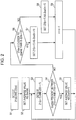
- Fig. 1 is a block diagram indicating the structure of the physical quantity measuring apparatus 10 according to this embodiment.
- the physical quantity measuring apparatus 10 has a first acceleration sensor 11, a second acceleration sensor 12, a control unit 13, a computing unit 14, a deciding unit 15, and a storage unit 16.
- the first acceleration sensor 11 and second acceleration sensor 12 are sensors of the same type. Each of them detects an acceleration as a physical quantity at detection times at intervals of a predetermined time, which is, for example, 10 ms. Detection results are output to the control unit 13.
- the sensors of the same type are sensors of a single type that detect the same physical quantity on the same principle.
- the acceleration sensors 11 and 12 detect a force when a mass moves along the direction of acceleration, and are composed of, for example, a beam that supports the mass and a distortion sensor that detects the distortion of the beam. The amount of distortion detected by the distortion sensor is proportional to the force.
- Three sensor units, each of which is composed of a mass, a beam, and a distortion sensor, are provided. The distortion direction of each beam is oriented to the direction of one of three axes so that accelerations in the triaxial directions of reference coordinate axes, which are mutually orthogonal.
- the control unit 13 controls the operations of the computing unit 14 and deciding unit 15, and outputs detection data by the first acceleration sensor 11 and second acceleration sensor 12 to the computing unit 14 or deciding unit 15 according to the time of detection. Furthermore, the control unit 13 causes the computing unit 14 to calculate a predetermined output value according to a decision result by the deciding unit 15.
- the computing unit 14 calculates an output value according to accelerations detected by the first acceleration sensor 11 and second acceleration sensor 12.
- the calculated output values are stored in the storage unit 16 through the control unit 13 and are also output to the deciding unit 15.
- the deciding unit 15 makes a predetermined decision according to an output value calculated by the computing unit 14 about the immediately preceding detection time and to accelerations detected by the first acceleration sensor 11 and second acceleration sensor 12 at the current detection time. This decision result is output through the control unit 13 to the computing unit 14.
- the computing unit 14 calculates an output value at each detection time according to the decision result by the deciding unit 15.
- an initial output value at the time of the activation of the physical quantity measuring apparatus 10 be the average value of accelerations detected by the first acceleration sensor 11 and second acceleration sensor 12 at their first detection times.
- the computing unit 14 calculates an output value as in (1) or (2).
- the deciding unit 15 decides whether there is a failure of the physical quantity measuring apparatus, which is, for example, a failure of the first acceleration sensor 11 or second acceleration sensor 12. More specifically, if the value of one of two physical quantities is predetermined times, which is for example, three times or more, the value of the other, the deciding unit 15 decides that there is a failure.
- a decision as the failure deciding unit is executed even in a case in which three are three or more acceleration sensors. If, for example, the value of a physical quantity detected by one acceleration sensor is predetermined times, which is for example, three times or more, the average value of the physical quantities detected by the remaining acceleration sensors, it is decided that there is a failure.
- Fig. 2 is a flowchart indicating a flow of processing of output value setting by the physical quantity measuring apparatus 10 in this embodiment.
- Fig. 3 and Fig. 4 are each a drawing indicating detected accelerations and setting examples of output values.
- Z1(n) is an acceleration detected by the first acceleration sensor 11 at detection time n
- Z2(n) is an acceleration detected by the second acceleration sensor 12 at detection time n.
- Detection time n+1 is a next detection time after detection time n.
- Zout(n) is an output value by the computing unit 14 at detection time n.
- first acceleration Z1(n) is detected by the first acceleration sensor 11 and second acceleration Z2(n) is detected by the second acceleration sensor 12 as an initial detection at the time of the activation of the physical quantity measuring apparatus 10 (step S1).
- These acceleration data items are output to the control unit 13.
- the control unit 13 commands the computing unit 14 to calculate an average value from the two detected accelerations.
- the computing unit 14 sets the calculated average value as output value Zout(n) at this time and this output value is stored in the storage unit 16 (step S2).
- output value Zout(n) is represented by equation (1) below.
- Zout n Z 1 n + Z 2 n / 2
- the first acceleration sensor 11 detects first acceleration Z1(n+1) and the second acceleration sensor 12 detects second acceleration Z2(n+1) (step S3).
- These acceleration data items are output to the control unit 13.
- the control unit 13 causes the deciding unit 15 to decide whether initial output value Zout(n) is present between the two accelerations, Z1(n+1) and Z2(n+1) (step S4).
- the time at the second detection is taken as the current detection time, the time at the initial detection becomes the immediately preceding detection time.
- Zout(n+1) Z 1 n + 1 + Z 2 n + 1 / 2
- the deciding unit 15 further decides whether first acceleration Z1(n+1) is closer to initial output value Zout(n) than is second acceleration Z2(n+1) (step S6).
- first acceleration Z1(n+1) is closer to initial output value Zout(n) than is second acceleration Z2(n+1) (YES in step S6), first acceleration Z1(n+1) is set as output value Zout(n+1) at this detection time (step S7).
- second acceleration Z2(n+1) is closer to initial output value Zout(n) than is first acceleration Z1(n+1) or first acceleration Z1(n+1) and second acceleration Z2(n+1) have the same value (NO in step S6), second acceleration Z2(n+1) is set as output value Zout(n+1) at this time (step S8).
- step S3 After steps S5, S7 and S8 above, processing in step S3 and subsequent steps is repeated by using a next detection time as the current detection time (step S9).
- step S6 it has been decided whether first acceleration Z1(n+1) is closer to initial output value Zout(n) than is second acceleration Z2(n+1), it may be decided whether second acceleration Z2(n+1) is closer to initial output value Zout(n) than is first acceleration Z1(n+1). In this case as well, an acceleration closer to initial output value Zout(n) is set as output value Zout(n+1) at this time as in steps S7 and S8 above.
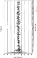
- Figs. 5 to 7 are each a graph indicating changes in outputs with respect to elapsed time when an acceleration sensor or a physical quantity measuring apparatus is placed in a stationary state.
- Fig. 5 indicates detected outputs of one acceleration sensor with broken lines L11.
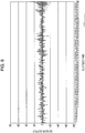
- Fig. 6 indicates average values of detected outputs of two acceleration sensors including the acceleration sensor used in Fig. 5 with dotted lines L12.
- Fig. 7 indicates output values in the physical quantity measuring apparatus, in this embodiment, including the two acceleration sensors used in Fig. 6 with solid lines L13.
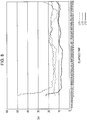
- Fig. 8 is a graph indicating changes in 3 ⁇ calculated from the values indicated in Fig. 5 to Fig. 7 with respect to elapsed time.
- the standard deviation ⁇ is a value calculated for a predetermined number of immediately preceding consecutive data items, which are, for example, consecutive 20 last data items, in data indicated in Fig. 5 to Fig. 7 , at each time.
- Fig. 8 it is found that the detected outputs (broken lines L11) by one acceleration sensor and the average values (dotted lines L12) of the detected outputs by two acceleration sensors have a large 3 ⁇ value and that the width of variations in the detected outputs or average values is large. In contrast to this, it is found that after the initial period has passed and the output values (solid lines L13) by the physical quantity measuring apparatus in this embodiment are stabilized, the output values are always smaller than the broken lines L11 and dotted lines L12 and that the width of variations in the output values is small.
- step S4 it is decided whether output value Zout(n) at the immediately preceding detection time is present between the maximum value and minimum value of the detected outputs by the three acceleration sensors. If output value Zout(n) is present between the maximum value and the minimum value, the average value of the three detected outputs is used as output value Zout(n+1) as in step S5.
- output value Zout(n) is not present between the maximum value and the minimum value
- the value that is included in the detected outputs by the three acceleration sensors and is closest to output value Zout(n) at the immediately preceding detection time is used as output value Zout(n+1) at the current detection time.
- a switchover may be made so that only one acceleration sensor is operated according to the situation.
- Control of a switchover is made by the control unit 13 as a switching unit. Due to this, when low power consumption is prioritized, the number of acceleration sensors to be operated can be reduced to 1 and output values can be calculated according to detection results of this acceleration sensor. When measurement precision is prioritized, two acceleration sensors can be operated and output values can be calculated according to the flow indicated in Fig. 2 . This switching of sensors is also true for three or more sensors. The number of sensors to be operated is switched according to the situation.
- the physical quantity measuring apparatus is advantageous in that power consumption, the size of the apparatus, and a load applied to a computing circuit can be suppressed and noise can also be suppressed.
Description
- The present invention relates to a physical quantity measuring apparatus having a plurality of physical quantity sensors of the same type.
- The movement measuring apparatus described in
PTL 1 converts angular velocity components detected by angular velocity sensors in triaxial directions to a quaternion, and also converts acceleration components detected by acceleration sensors in triaxial directions to a quaternion. The movement measuring apparatus then applies a Kalman filter to correct the quaternion converted from the angular velocity components by using the quaternion converted from the acceleration components as observed values. Due to this, the movement measuring apparatus aims at precisely obtaining the motion angles of the lower limbs and the like during walking through a quick computation. -
US 2012/245895 A1 discloses a scheme of detecting a sensor failure based on a prior received sensor value and a filtered rate of change value that is calculated based on a prior rate of change value. - PTL 1: Japanese Unexamined Patent Application Publication No.
2015-217053 - The present invention relates to a physical quantity measuring apparatus and a method according to the appended claims.
- With the movement measuring apparatus described in
PTL 1, however, angular velocity sensors and acceleration sensors are used and filtering is performed in computations, so there is the problem that power consumption is increased, an area used to install circuits corresponding to a plurality of sensors of different types is enlarged, and a load applied to a computing circuit is also increased. - On the other hand, as a method of calculating a position, there is a method of integrating accelerations detected by an acceleration sensor. However, in a process of integration from an acceleration to a velocity and integration from a velocity to a point, a noise signal included in acceleration data is superimposed, so there is the problem that it is difficult to perform highly precious position calculations.
- Therefore, an object of the present invention is to provide a physical quantity measuring apparatus that can suppress power consumption, the size of the apparatus, and a load applied to a computing circuit and can perform highly precise physical quantity computations by suppressing noise, without using a special filter such as a Kalman filter.
- To address the above problems, a physical quantity measuring apparatus in the present invention is defined in
claim 1 and a corresponding method is defined in claim 7. - Due to this, it becomes possible to suppress power consumption, the size of the apparatus, and a load applied to a computing circuit and to perform highly precise physical quantity computations by suppressing noise, without using a special filter.
- In the physical quantity measuring apparatus in the present invention: the plurality of physical quantity sensors are preferably two physical quantity sensor.
- In the physical quantity measuring apparatus in the present invention, the need to use a special filter or a complex circuit is eliminated and noise can be reliably and easily suppressed.
- In the physical quantity measuring apparatus in the present invetion, the initial output value of the output value is preferably the average value of physical quantities detected by the plurality of physical quantity sensors at a first time.
- Due to this, it is sufficient to calculate an average value, so a load applied to a computing circuit can be reduced and processing by the computing unit and deciding unit can be quickly and accurately performed.
- In the physical quantity measuring apparatus in the present invention, a switching unit is preferably provided that switches the number of physical quantity sensors, included in the plurality of physical quantity sensors, to be operated.
- Due to this, when low power consumption is prioritized, the number of acceleration sensors to be operated can be reduced. Also, by increasing the number of acceleration sensors to be operated, measurement precision can be increased.
- In the physical quantity measuring apparatus in the present invention, the deciding unit preferably makes a failure decision about the physical quantity measuring apparatus by comparing physical quantities detected by the plurality of physical quantity sensors.
- Due to this, it becomes possible to recognize a failure in the physical quantity measuring apparatus, so an action can be quickly taken to, for example, replace a physical quantity sensor or switch the number of physical quantity sensors to be operated and precision in physical quantity measurement can thereby be maintained.
- According to the present invention, it is possible to suppress power consumption, the size of the apparatus, and a load applied to a computing circuit and to perform highly precise physical quantity computations by suppressing noise, without using a special filter such as a Kalman filter. Brief Description of Drawings
- [
Fig. 1] Fig. 1 is a block diagram indicating the structure of a physical quantity measuring apparatus according to an embodiment of the present invention. - [
Fig. 2] Fig. 2 is a flowchart indicating a flow of processing of output value setting by the physical quantity measuring apparatus according to an embodiment of the present invention. - [
Fig. 3] Fig. 3 is a drawing indicating detected accelerations and setting examples of output values. - [
Fig. 4] Fig. 4 is a drawing indicating detected accelerations and setting examples of output values. - [
Fig. 5] Fig. 5 is a graph indicating changes in detected outputs with respect to elapsed time when one acceleration sensor is placed in a stationary state. - [
Fig. 6] Fig. 6 is a graph indicating changes in average values of detected outputs with respect to elapsed time when two acceleration sensors are placed in a stationary state. - [
Fig. 7] Fig. 7 is a graph indicating changes in output values with respect to elapsed time when the physical quantity measuring apparatus is placed in a stationary state. - [
Fig. 8] Fig. 8 is a graph indicating changes in 3σ calculated from values indicated inFig. 5 to Fig. 7 with respect to elapsed time. - A physical quantity measuring apparatus according to an embodiment of the present invention will be described below in detail while the drawings are referenced. Although, in this embodiment, a case in which two acceleration sensors are used as physical quantity sensors will be described, the physical quantity sensors in the present invention are not limited to acceleration sensors. The present invention can also be applied to, for example, angular velocity sensor, atmospheric pressure sensors, optical sensors, temperature sensors, weight sensors, and the like.
-
Fig. 1 is a block diagram indicating the structure of the physicalquantity measuring apparatus 10 according to this embodiment. As indicated inFig. 1 , the physicalquantity measuring apparatus 10 has afirst acceleration sensor 11, asecond acceleration sensor 12, acontrol unit 13, acomputing unit 14, a decidingunit 15, and astorage unit 16. - The
first acceleration sensor 11 andsecond acceleration sensor 12 are sensors of the same type. Each of them detects an acceleration as a physical quantity at detection times at intervals of a predetermined time, which is, for example, 10 ms. Detection results are output to thecontrol unit 13. Here, the sensors of the same type are sensors of a single type that detect the same physical quantity on the same principle. Theacceleration sensors - The
control unit 13 controls the operations of thecomputing unit 14 and decidingunit 15, and outputs detection data by thefirst acceleration sensor 11 andsecond acceleration sensor 12 to thecomputing unit 14 or decidingunit 15 according to the time of detection. Furthermore, thecontrol unit 13 causes thecomputing unit 14 to calculate a predetermined output value according to a decision result by the decidingunit 15. - At detection times at intervals of the above predetermined time, under control of the
control unit 13, thecomputing unit 14 calculates an output value according to accelerations detected by thefirst acceleration sensor 11 andsecond acceleration sensor 12. The calculated output values are stored in thestorage unit 16 through thecontrol unit 13 and are also output to the decidingunit 15. Under control of thecontrol unit 13, the decidingunit 15 makes a predetermined decision according to an output value calculated by thecomputing unit 14 about the immediately preceding detection time and to accelerations detected by thefirst acceleration sensor 11 andsecond acceleration sensor 12 at the current detection time. This decision result is output through thecontrol unit 13 to thecomputing unit 14. Thecomputing unit 14 calculates an output value at each detection time according to the decision result by the decidingunit 15. - Here, it is preferable that an initial output value at the time of the activation of the physical
quantity measuring apparatus 10 be the average value of accelerations detected by thefirst acceleration sensor 11 andsecond acceleration sensor 12 at their first detection times. - As a decision by the deciding
unit 15, there is a decision as to whether an output value calculated by thecomputing unit 14 about the immediately preceding detection time is present between two accelerations detected by thefirst acceleration sensor 11 andsecond acceleration sensor 12 at the current detection time. According to this decision result, thecomputing unit 14 calculates an output value as in (1) or (2). - (1) If the output value calculated about the immediately preceding detection time is present between the accelerations detected by the
first acceleration sensor 11 andsecond acceleration sensor 12 at the current detection time, the average value of the accelerations detected by thefirst acceleration sensor 11 andsecond acceleration sensor 12 at the current detection time is used as the output value about the current detection time. - (2) If the output value calculated about the immediately preceding detection time is not present between the accelerations detected by the
first acceleration sensor 11 andsecond acceleration sensor 12 at the current detection time, of the two accelerations detected about the current detection time, an acceleration close to the output value calculated about the immediately preceding detection time is used as the output value about the current detection time. Here, a decision as to which of the two accelerations detected about the current detection time is close to the output value calculated about the immediately preceding detection time is also made by the decidingunit 15. - Also, by comparing physical quantities detected by the
first acceleration sensor 11 andsecond acceleration sensor 12 as a failure deciding unit, the decidingunit 15 decides whether there is a failure of the physical quantity measuring apparatus, which is, for example, a failure of thefirst acceleration sensor 11 orsecond acceleration sensor 12. More specifically, if the value of one of two physical quantities is predetermined times, which is for example, three times or more, the value of the other, the decidingunit 15 decides that there is a failure. - Here, a decision as the failure deciding unit is executed even in a case in which three are three or more acceleration sensors. If, for example, the value of a physical quantity detected by one acceleration sensor is predetermined times, which is for example, three times or more, the average value of the physical quantities detected by the remaining acceleration sensors, it is decided that there is a failure.
-
Fig. 2 is a flowchart indicating a flow of processing of output value setting by the physicalquantity measuring apparatus 10 in this embodiment.Fig. 3 andFig. 4 are each a drawing indicating detected accelerations and setting examples of output values. InFig. 2 to Fig. 4 , Z1(n) is an acceleration detected by thefirst acceleration sensor 11 at detection time n, and Z2(n) is an acceleration detected by thesecond acceleration sensor 12 at detection time n. Detection time n+1 is a next detection time after detection time n. Zout(n) is an output value by thecomputing unit 14 at detection time n. - First, first acceleration Z1(n) is detected by the
first acceleration sensor 11 and second acceleration Z2(n) is detected by thesecond acceleration sensor 12 as an initial detection at the time of the activation of the physical quantity measuring apparatus 10 (step S1). These acceleration data items are output to thecontrol unit 13. Thecontrol unit 13 commands thecomputing unit 14 to calculate an average value from the two detected accelerations. Thecomputing unit 14 sets the calculated average value as output value Zout(n) at this time and this output value is stored in the storage unit 16 (step S2). Here, output value Zout(n) is represented by equation (1) below.
- In a second detection after a predetermined time has passed from the detection in step S1 above, the
first acceleration sensor 11 detects first acceleration Z1(n+1) and thesecond acceleration sensor 12 detects second acceleration Z2(n+1) (step S3). These acceleration data items are output to thecontrol unit 13. Thecontrol unit 13 causes the decidingunit 15 to decide whether initial output value Zout(n) is present between the two accelerations, Z1(n+1) and Z2(n+1) (step S4). Here, if the time at the second detection is taken as the current detection time, the time at the initial detection becomes the immediately preceding detection time. - As indicated in
Fig. 3 , if initial output value Zout(n) was present between the two accelerations, Z1(n+1) and Z2(n+1) (YES in step S4), thecontrol unit 13 causes thecomputing unit 14 to calculate the average value of the two accelerations, Z1(n+1) and Z2(n+1), thecomputing unit 14 sets the calculated average value as output value Zout(n+1) at this time, and this output value is stored in the storage unit 16 (step S5). Here, Zout(n+1) is represented by equation (2) below. Incidentally, although Zout(n) is deviated from detection time n inFig. 3 and Zout(n+1) is deviated from detection time n+1 inFig. 4 , these deviations are made for convenience of explanation.
- On the other hand, as indicated in
Fig. 4 , if initial output value Zout(n) was not present between the two accelerations, Z1(n+1) and Z2(n+1) (NO in step S4), the decidingunit 15 further decides whether first acceleration Z1(n+1) is closer to initial output value Zout(n) than is second acceleration Z2(n+1) (step S6). - As a result, if first acceleration Z1(n+1) is closer to initial output value Zout(n) than is second acceleration Z2(n+1) (YES in step S6), first acceleration Z1(n+1) is set as output value Zout(n+1) at this detection time (step S7).
- In contrast to this, if second acceleration Z2(n+1) is closer to initial output value Zout(n) than is first acceleration Z1(n+1) or first acceleration Z1(n+1) and second acceleration Z2(n+1) have the same value (NO in step S6), second acceleration Z2(n+1) is set as output value Zout(n+1) at this time (step S8).
- After steps S5, S7 and S8 above, processing in step S3 and subsequent steps is repeated by using a next detection time as the current detection time (step S9).
- Here, although, in step S6 above, it has been decided whether first acceleration Z1(n+1) is closer to initial output value Zout(n) than is second acceleration Z2(n+1), it may be decided whether second acceleration Z2(n+1) is closer to initial output value Zout(n) than is first acceleration Z1(n+1). In this case as well, an acceleration closer to initial output value Zout(n) is set as output value Zout(n+1) at this time as in steps S7 and S8 above.
-
Figs. 5 to 7 are each a graph indicating changes in outputs with respect to elapsed time when an acceleration sensor or a physical quantity measuring apparatus is placed in a stationary state.Fig. 5 indicates detected outputs of one acceleration sensor with broken lines L11.Fig. 6 indicates average values of detected outputs of two acceleration sensors including the acceleration sensor used inFig. 5 with dotted lines L12.Fig. 7 indicates output values in the physical quantity measuring apparatus, in this embodiment, including the two acceleration sensors used inFig. 6 with solid lines L13.Fig. 8 is a graph indicating changes in 3σ calculated from the values indicated inFig. 5 to Fig. 7 with respect to elapsed time. Here, the standard deviation σ is a value calculated for a predetermined number of immediately preceding consecutive data items, which are, for example, consecutive 20 last data items, in data indicated inFig. 5 to Fig. 7 , at each time. - When
Fig. 5 to Fig. 7 are compared, in detected outputs by one acceleration sensor (broken lines L11 inFig. 5 ), variations in the detected outputs are large in spite of the acceleration sensor being stationary, so an influence of noise is seen. In contrast to this, in the average values (dotted lines L12 inFig. 6 ) of the detected outputs by two acceleration sensors, time periods during which variations are excessive are lessened when compared with a case inFig. 5 , but the amount of variations is still large, so an influence of noise is seen. On the other hand, in the output values (solid lines L13 inFig. 7 ) by the physical quantity measuring apparatus in this embodiment, after an initial period during which the apparatus was set has passed, variations are less and stable at values near 0, so it is found that the influence of the noise was able to be suppressed. - In
Fig. 8 , it is found that the detected outputs (broken lines L11) by one acceleration sensor and the average values (dotted lines L12) of the detected outputs by two acceleration sensors have a large 3σ value and that the width of variations in the detected outputs or average values is large. In contrast to this, it is found that after the initial period has passed and the output values (solid lines L13) by the physical quantity measuring apparatus in this embodiment are stabilized, the output values are always smaller than the broken lines L11 and dotted lines L12 and that the width of variations in the output values is small. - Due to the above structure, according to the above embodiment, the following effects are obtained.
- (1) Since a special filter is not used and it is sufficient to use a plurality of physical quantity sensors of the same type, it is possible to suppress power consumption, the size of the apparatus, and a load applied to a computing circuit.
- (2) Since processing is continued in which an output value at the immediately preceding detection time or a detected value close to this output value is selected by using a plurality of physical quantity sensors, stable output values with the influence of noise suppressed can be obtained. In contrast to this, a Kalman filter, for example, is a theory expanded from a moving average and can only average variations in detected outputs of individual sensors, so it is difficult to reliably suppress noise.
- A variation will be described below.
- Although an example in which two acceleration sensors are used has been described in the above embodiment, three or more acceleration sensors can also be used. In this case as well, output values can be set in a flow similar to the flow indicated in
Fig. 2 . More specifically, processing in steps S1 to S3 inFig. 2 is similar in the case of three acceleration sensors as well. In decision processing in next step S4, it is decided whether output value Zout(n) at the immediately preceding detection time is present between the maximum value and minimum value of the detected outputs by the three acceleration sensors. If output value Zout(n) is present between the maximum value and the minimum value, the average value of the three detected outputs is used as output value Zout(n+1) as in step S5. On the other hand, if output value Zout(n) is not present between the maximum value and the minimum value, the value that is included in the detected outputs by the three acceleration sensors and is closest to output value Zout(n) at the immediately preceding detection time is used as output value Zout(n+1) at the current detection time. By using three or more acceleration sensors in this way, noise can be more easily suppressed and highly precise physical quantity computation becomes possible. - Also, although both of the two acceleration sensors have continued to be operated in the above embodiment, a switchover may be made so that only one acceleration sensor is operated according to the situation. Control of a switchover is made by the
control unit 13 as a switching unit. Due to this, when low power consumption is prioritized, the number of acceleration sensors to be operated can be reduced to 1 and output values can be calculated according to detection results of this acceleration sensor. When measurement precision is prioritized, two acceleration sensors can be operated and output values can be calculated according to the flow indicated inFig. 2 . This switching of sensors is also true for three or more sensors. The number of sensors to be operated is switched according to the situation. - The present invention has been described while the above embodiment has been referenced. However, the present invention is not limited to the above embodiment but it is defined by the appended claims.
- As described above, the physical quantity measuring apparatus according to the present invention is advantageous in that power consumption, the size of the apparatus, and a load applied to a computing circuit can be suppressed and noise can also be suppressed.
-
- 10 physical quantity measuring apparatus
- 11 first acceleration sensor
- 12 second acceleration sensor
- 13 control unit
- 14 computing unit
- 15 deciding unit
- L11 detected output by one acceleration sensor
- L12 average value of detected outputs by two acceleration sensors
- L13 output value by physical quantity measuring apparatus
- Zl(n), Z1(n+1) detected output by first acceleration sensor
- Z2(n), Z2(n+1) detected output by second acceleration sensor
- Zout(n) output value
Claims (10)
- A physical quantity measuring apparatus comprising:a plurality of physical quantity sensors (11, 12) of the same type, each of which is configured to detect a physical quantity at detection times at intervals of a predetermined time;a computing unit (14) configured to calculate an output value according to physical quantities detected by the plurality of physical quantity sensors (11, 12) at each detection time; anda deciding unit (15) configured to make a predetermined decision according to an output value calculated about an immediately preceding detection time and to physical quantities detected by the plurality of physical quantity sensors (11, 12) at a current detection time; whereinthe computing unit (14) is configured to calculate an output value at each time according to a decision result by the deciding unit (15),characterised in thatthe computing unit (15) is further configured to calculate an average value of the physical quantities detected by the plurality of physical quantity sensors (11, 12) at the immediately preceding detection time,the deciding unit (15) is further configured to determine whether the average value is present between a maximum value and a minimum value of the physical quantities detected by the plurality of physical quantity sensors (11, 12) at the current detection time, andthe computing unit (15) is further configured to set the average value of the physical quantities detected by two physical quantity sensors at the current detection time as the output value when the determination result is positive, and to set one of the physical quantitie detected at the current detection time, which is closest to the average value, as the output value when the determination result is negative.
- The physical quantity measuring apparatus according to Claim 1, wherein the plurality of physical quantity sensors are two physical quantity sensors.
- The physical quantity measuring apparatus according to Claim 1, wherein an initial output value of the output value is an average value of physical quantities detected by the plurality of physical quantity sensors (11, 12) at a first time.
- The physical quantity measuring apparatus according to any one of Claim 1 to Claim 3, wherein a switching unit is provided that switches the number of physical quantity sensors, included in the plurality of physical quantity sensors, to be operated.
- The physical quantity measuring apparatus according to any one of Claim 1 to Claim 4, wherein the deciding unit (15) is further configured to make a failure decision about the physical quantity measuring apparatus by comparing physical quantities detected by the plurality of physical quantity sensors (11, 12).
- The physical quantity measuring apparatus according to any one of Claim 1 to Claim 5, wherein the type of physical quantity sensors is any of an acceleration sensor, an angular velocity sensor, an atmospheric pressure sensor, an optical sensor or a weight sensor.
- A method of measuring a physical quantity using a plurality of physical quantity sensors (11, 12) of the same type, the method comprising:detecting a physical quantity by each of the plurality of physical quantity sensors (11, 12) at detection times at intervals of a predetermined time;calculating an average value of the physical quantities detected by the plurality of physical quantity sensors (11, 12) at an immediately preceding detection time;determining whether the average value is present between a maximum value and a minimum value of the physical quantities detected by the plurality of physical quantity sensors (11, 12) at a current detection time;setting the average value of the physical quantities detected by two physical quantity sensors at the current detection time as an output value when the determination result is positive; andsetting one of the physical quantities detected at the current detection time, which is closest to the average value, as the output value when the determination result is negative.
- The method of claim 7, wherein the number of the plurality of physical quantity sensors (11, 12) is two.
- The method of claim 7 or 8, wherein an initial output value of the output value is an average value of physical quantities detected by the plurality of physical quantity sensors (11, 12) at a first time.
- The method of any of claims 7-9, wherein the type of physical quantity sensors is any of an acceleration sensor, an angular velocity sensor, an atmospheric pressure sensor, an optical sensor or a weight sensor.
Applications Claiming Priority (2)
| Application Number | Priority Date | Filing Date | Title |
|---|---|---|---|
| JP2016180805 | 2016-09-15 | ||
| PCT/JP2017/008460 WO2018051538A1 (en) | 2016-09-15 | 2017-03-03 | Physical quantity measurement device |
Publications (3)
| Publication Number | Publication Date |
|---|---|
| EP3514498A1 EP3514498A1 (en) | 2019-07-24 |
| EP3514498A4 EP3514498A4 (en) | 2020-05-06 |
| EP3514498B1 true EP3514498B1 (en) | 2021-05-05 |
Family
ID=61618893
Family Applications (1)
| Application Number | Title | Priority Date | Filing Date |
|---|---|---|---|
| EP17850446.0A Active EP3514498B1 (en) | 2016-09-15 | 2017-03-03 | Physical quantity measurement device |
Country Status (5)
| Country | Link |
|---|---|
| US (1) | US11085801B2 (en) |
| EP (1) | EP3514498B1 (en) |
| JP (1) | JP6757798B2 (en) |
| CN (1) | CN109716070B (en) |
| WO (1) | WO2018051538A1 (en) |
Families Citing this family (2)
| Publication number | Priority date | Publication date | Assignee | Title |
|---|---|---|---|---|
| US20220252399A1 (en) * | 2019-01-28 | 2022-08-11 | Panasonic Intellectual Property Management Co., Ltd. | Composite sensor and angular velocity correction method |
| JP2023042084A (en) * | 2021-09-14 | 2023-03-27 | セイコーエプソン株式会社 | inertial sensor module |
Family Cites Families (18)
| Publication number | Priority date | Publication date | Assignee | Title |
|---|---|---|---|---|
| DE1495137A1 (en) | 1963-09-04 | 1968-12-12 | Basf Ag | Process for the production of modified polyolefin waxes |
| US3530381A (en) * | 1968-01-15 | 1970-09-22 | Coulter Electronics | Voting circuit control apparatus for multiple aperture particle analyzing device |
| JPS625402A (en) * | 1985-07-01 | 1987-01-12 | Hitachi Ltd | Plant controller |
| JP3127350B2 (en) * | 1995-07-20 | 2001-01-22 | 本田技研工業株式会社 | Control device for lock-up clutch |
| US6430295B1 (en) | 1997-07-11 | 2002-08-06 | Telefonaktiebolaget Lm Ericsson (Publ) | Methods and apparatus for measuring signal level and delay at multiple sensors |
| DE10145485B4 (en) * | 2001-09-14 | 2007-12-27 | Siemens Ag | Method and device for diagnosing a sensor |
| EP2060875B1 (en) | 2006-09-12 | 2019-11-06 | Asahi Kasei Microdevices Corporation | Physical quantity measuring instrument and signal processing method thereof |
| US9501803B2 (en) * | 2007-04-12 | 2016-11-22 | Siemens Industry, Inc. | Devices, systems, and methods for monitoring energy systems |
| US9404775B2 (en) * | 2008-04-30 | 2016-08-02 | Honeywell International Inc. | Systems and methods for identifying faulty sensors |
| WO2012050475A1 (en) * | 2010-10-11 | 2012-04-19 | General Electric Company | Systems, methods, and apparatus for signal processing- based fault detection, isolation and remediation |
| US9207670B2 (en) * | 2011-03-21 | 2015-12-08 | Rosemount Inc. | Degrading sensor detection implemented within a transmitter |
| JP6215527B2 (en) | 2012-02-02 | 2017-10-18 | 旭化成エレクトロニクス株式会社 | Physical quantity measuring apparatus and physical quantity measuring method |
| EP2818836B1 (en) * | 2012-02-24 | 2016-04-27 | Asahi Kasei Microdevices Corporation | Sensor device with sampling function, and sensor data processing system using same |
| JP6210187B2 (en) * | 2012-10-23 | 2017-10-11 | セイコーエプソン株式会社 | Integrated circuit device, physical quantity measuring device, electronic device, and moving object |
| US9702349B2 (en) * | 2013-03-15 | 2017-07-11 | ClearMotion, Inc. | Active vehicle suspension system |
| JP2015072188A (en) * | 2013-10-03 | 2015-04-16 | セイコーエプソン株式会社 | Physical quantity detection element, physical quantity detection device, electronic apparatus and moving body |
| JP2015217053A (en) | 2014-05-15 | 2015-12-07 | 国立大学法人東北大学 | Movement measuring apparatus and movement measuring method |
| US10203804B2 (en) | 2014-11-26 | 2019-02-12 | Alps Electric Co., Ltd. | Input device, and control method and program therefor |
-
2017
- 2017-03-03 EP EP17850446.0A patent/EP3514498B1/en active Active
- 2017-03-03 JP JP2018539500A patent/JP6757798B2/en active Active
- 2017-03-03 CN CN201780056633.6A patent/CN109716070B/en active Active
- 2017-03-03 WO PCT/JP2017/008460 patent/WO2018051538A1/en unknown
-
2019
- 2019-03-14 US US16/353,190 patent/US11085801B2/en active Active
Also Published As
| Publication number | Publication date |
|---|---|
| EP3514498A1 (en) | 2019-07-24 |
| CN109716070A (en) | 2019-05-03 |
| EP3514498A4 (en) | 2020-05-06 |
| US11085801B2 (en) | 2021-08-10 |
| CN109716070B (en) | 2021-07-23 |
| JPWO2018051538A1 (en) | 2019-07-04 |
| US20190204125A1 (en) | 2019-07-04 |
| JP6757798B2 (en) | 2020-09-23 |
| WO2018051538A1 (en) | 2018-03-22 |
Similar Documents
| Publication | Publication Date | Title |
|---|---|---|
| EP1760431B1 (en) | Inertial navigation system with a plurality of Kalman filters and vehicle equipped with such a system | |
| US8589113B2 (en) | Movement detection device, electronic device, movement detection method and storage medium stored with a program | |
| CN107796387B (en) | Positioning method, positioning device and electronic equipment | |
| EP3006913A1 (en) | Physical quantity sensor adjustment method, and physical quantity sensor | |
| CN109425753B (en) | Hybrid altimeter for measuring vertical velocity | |
| CN111811521A (en) | Positioning method and device, electronic equipment, vehicle-end equipment and automatic driving vehicle | |
| EP2910954B1 (en) | Method for counting steps and electronic apparatus using the same | |
| EP3514498B1 (en) | Physical quantity measurement device | |
| CN105698788B (en) | System and method for generating two independent and distinct attitude solutions, inertial solutions, or both | |
| CN105547291B (en) | The adaptive static detection method of indoor occupant freedom positioning system | |
| EP3239796A1 (en) | Failure diagnostic method and failure diagnostic system | |
| US20140100816A1 (en) | Filter activation and deactivation based on comparative rates | |
| WO2017141469A1 (en) | Position estimation device | |
| JP5338705B2 (en) | Exercise state detection method and exercise state detection device | |
| KR102006029B1 (en) | Method and Apparatus for calculation azimuth | |
| JP2013181900A (en) | Orientation calculation method, position calculation method, and orientation calculation device | |
| US10345329B2 (en) | Inertial force sensor | |
| EP2894534B1 (en) | Slew rate detection circuit | |
| KR101214733B1 (en) | Device for detecting double motion and method for detecting double motion | |
| EP3893004A1 (en) | Electronic device, correction method, and program | |
| Božek et al. | Reverse validation of a programmed robot trajectory based on INS | |
| EP3250888B1 (en) | Multiple sensor integration | |
| US20160179282A1 (en) | Background signal processing system and background signal processing method | |
| KR20170085744A (en) | Adaptive Attitude Reference System Using Sequential Measurement Norm Covariance | |
| US9569033B2 (en) | Background signal processing system and background signal processing method |
Legal Events
| Date | Code | Title | Description |
|---|---|---|---|
| STAA | Information on the status of an ep patent application or granted ep patent |
Free format text: STATUS: THE INTERNATIONAL PUBLICATION HAS BEEN MADE |
|
| PUAI | Public reference made under article 153(3) epc to a published international application that has entered the european phase |
Free format text: ORIGINAL CODE: 0009012 |
|
| STAA | Information on the status of an ep patent application or granted ep patent |
Free format text: STATUS: REQUEST FOR EXAMINATION WAS MADE |
|
| 17P | Request for examination filed |
Effective date: 20190314 |
|
| AK | Designated contracting states |
Kind code of ref document: A1 Designated state(s): AL AT BE BG CH CY CZ DE DK EE ES FI FR GB GR HR HU IE IS IT LI LT LU LV MC MK MT NL NO PL PT RO RS SE SI SK SM TR |
|
| AX | Request for extension of the european patent |
Extension state: BA ME |
|
| DAV | Request for validation of the european patent (deleted) | ||
| DAX | Request for extension of the european patent (deleted) | ||
| A4 | Supplementary search report drawn up and despatched |
Effective date: 20200403 |
|
| RIC1 | Information provided on ipc code assigned before grant |
Ipc: G01C 19/00 20130101ALI20200330BHEP Ipc: G01P 15/00 20060101ALI20200330BHEP Ipc: G01D 3/00 20060101AFI20200330BHEP |
|
| GRAP | Despatch of communication of intention to grant a patent |
Free format text: ORIGINAL CODE: EPIDOSNIGR1 |
|
| STAA | Information on the status of an ep patent application or granted ep patent |
Free format text: STATUS: GRANT OF PATENT IS INTENDED |
|
| INTG | Intention to grant announced |
Effective date: 20201201 |
|
| GRAS | Grant fee paid |
Free format text: ORIGINAL CODE: EPIDOSNIGR3 |
|
| GRAA | (expected) grant |
Free format text: ORIGINAL CODE: 0009210 |
|
| STAA | Information on the status of an ep patent application or granted ep patent |
Free format text: STATUS: THE PATENT HAS BEEN GRANTED |
|
| AK | Designated contracting states |
Kind code of ref document: B1 Designated state(s): AL AT BE BG CH CY CZ DE DK EE ES FI FR GB GR HR HU IE IS IT LI LT LU LV MC MK MT NL NO PL PT RO RS SE SI SK SM TR |
|
| REG | Reference to a national code |
Ref country code: GB Ref legal event code: FG4D |
|
| REG | Reference to a national code |
Ref country code: CH Ref legal event code: EP |
|
| REG | Reference to a national code |
Ref country code: AT Ref legal event code: REF Ref document number: 1390358 Country of ref document: AT Kind code of ref document: T Effective date: 20210515 |
|
| REG | Reference to a national code |
Ref country code: IE Ref legal event code: FG4D |
|
| REG | Reference to a national code |
Ref country code: DE Ref legal event code: R096 Ref document number: 602017038336 Country of ref document: DE |
|
| REG | Reference to a national code |
Ref country code: LT Ref legal event code: MG9D |
|
| REG | Reference to a national code |
Ref country code: AT Ref legal event code: MK05 Ref document number: 1390358 Country of ref document: AT Kind code of ref document: T Effective date: 20210505 |
|
| PG25 | Lapsed in a contracting state [announced via postgrant information from national office to epo] |
Ref country code: BG Free format text: LAPSE BECAUSE OF FAILURE TO SUBMIT A TRANSLATION OF THE DESCRIPTION OR TO PAY THE FEE WITHIN THE PRESCRIBED TIME-LIMIT Effective date: 20210805 Ref country code: AT Free format text: LAPSE BECAUSE OF FAILURE TO SUBMIT A TRANSLATION OF THE DESCRIPTION OR TO PAY THE FEE WITHIN THE PRESCRIBED TIME-LIMIT Effective date: 20210505 Ref country code: HR Free format text: LAPSE BECAUSE OF FAILURE TO SUBMIT A TRANSLATION OF THE DESCRIPTION OR TO PAY THE FEE WITHIN THE PRESCRIBED TIME-LIMIT Effective date: 20210505 Ref country code: FI Free format text: LAPSE BECAUSE OF FAILURE TO SUBMIT A TRANSLATION OF THE DESCRIPTION OR TO PAY THE FEE WITHIN THE PRESCRIBED TIME-LIMIT Effective date: 20210505 Ref country code: LT Free format text: LAPSE BECAUSE OF FAILURE TO SUBMIT A TRANSLATION OF THE DESCRIPTION OR TO PAY THE FEE WITHIN THE PRESCRIBED TIME-LIMIT Effective date: 20210505 |
|
| PG25 | Lapsed in a contracting state [announced via postgrant information from national office to epo] |
Ref country code: IS Free format text: LAPSE BECAUSE OF FAILURE TO SUBMIT A TRANSLATION OF THE DESCRIPTION OR TO PAY THE FEE WITHIN THE PRESCRIBED TIME-LIMIT Effective date: 20210905 Ref country code: GR Free format text: LAPSE BECAUSE OF FAILURE TO SUBMIT A TRANSLATION OF THE DESCRIPTION OR TO PAY THE FEE WITHIN THE PRESCRIBED TIME-LIMIT Effective date: 20210806 Ref country code: RS Free format text: LAPSE BECAUSE OF FAILURE TO SUBMIT A TRANSLATION OF THE DESCRIPTION OR TO PAY THE FEE WITHIN THE PRESCRIBED TIME-LIMIT Effective date: 20210505 Ref country code: SE Free format text: LAPSE BECAUSE OF FAILURE TO SUBMIT A TRANSLATION OF THE DESCRIPTION OR TO PAY THE FEE WITHIN THE PRESCRIBED TIME-LIMIT Effective date: 20210505 Ref country code: PL Free format text: LAPSE BECAUSE OF FAILURE TO SUBMIT A TRANSLATION OF THE DESCRIPTION OR TO PAY THE FEE WITHIN THE PRESCRIBED TIME-LIMIT Effective date: 20210505 Ref country code: PT Free format text: LAPSE BECAUSE OF FAILURE TO SUBMIT A TRANSLATION OF THE DESCRIPTION OR TO PAY THE FEE WITHIN THE PRESCRIBED TIME-LIMIT Effective date: 20210906 Ref country code: LV Free format text: LAPSE BECAUSE OF FAILURE TO SUBMIT A TRANSLATION OF THE DESCRIPTION OR TO PAY THE FEE WITHIN THE PRESCRIBED TIME-LIMIT Effective date: 20210505 Ref country code: NO Free format text: LAPSE BECAUSE OF FAILURE TO SUBMIT A TRANSLATION OF THE DESCRIPTION OR TO PAY THE FEE WITHIN THE PRESCRIBED TIME-LIMIT Effective date: 20210805 |
|
| REG | Reference to a national code |
Ref country code: NL Ref legal event code: MP Effective date: 20210505 |
|
| PG25 | Lapsed in a contracting state [announced via postgrant information from national office to epo] |
Ref country code: NL Free format text: LAPSE BECAUSE OF FAILURE TO SUBMIT A TRANSLATION OF THE DESCRIPTION OR TO PAY THE FEE WITHIN THE PRESCRIBED TIME-LIMIT Effective date: 20210505 |
|
| PG25 | Lapsed in a contracting state [announced via postgrant information from national office to epo] |
Ref country code: ES Free format text: LAPSE BECAUSE OF FAILURE TO SUBMIT A TRANSLATION OF THE DESCRIPTION OR TO PAY THE FEE WITHIN THE PRESCRIBED TIME-LIMIT Effective date: 20210505 Ref country code: EE Free format text: LAPSE BECAUSE OF FAILURE TO SUBMIT A TRANSLATION OF THE DESCRIPTION OR TO PAY THE FEE WITHIN THE PRESCRIBED TIME-LIMIT Effective date: 20210505 Ref country code: SM Free format text: LAPSE BECAUSE OF FAILURE TO SUBMIT A TRANSLATION OF THE DESCRIPTION OR TO PAY THE FEE WITHIN THE PRESCRIBED TIME-LIMIT Effective date: 20210505 Ref country code: SK Free format text: LAPSE BECAUSE OF FAILURE TO SUBMIT A TRANSLATION OF THE DESCRIPTION OR TO PAY THE FEE WITHIN THE PRESCRIBED TIME-LIMIT Effective date: 20210505 Ref country code: DK Free format text: LAPSE BECAUSE OF FAILURE TO SUBMIT A TRANSLATION OF THE DESCRIPTION OR TO PAY THE FEE WITHIN THE PRESCRIBED TIME-LIMIT Effective date: 20210505 Ref country code: CZ Free format text: LAPSE BECAUSE OF FAILURE TO SUBMIT A TRANSLATION OF THE DESCRIPTION OR TO PAY THE FEE WITHIN THE PRESCRIBED TIME-LIMIT Effective date: 20210505 Ref country code: RO Free format text: LAPSE BECAUSE OF FAILURE TO SUBMIT A TRANSLATION OF THE DESCRIPTION OR TO PAY THE FEE WITHIN THE PRESCRIBED TIME-LIMIT Effective date: 20210505 |
|
| REG | Reference to a national code |
Ref country code: DE Ref legal event code: R097 Ref document number: 602017038336 Country of ref document: DE |
|
| PLBE | No opposition filed within time limit |
Free format text: ORIGINAL CODE: 0009261 |
|
| STAA | Information on the status of an ep patent application or granted ep patent |
Free format text: STATUS: NO OPPOSITION FILED WITHIN TIME LIMIT |
|
| 26N | No opposition filed |
Effective date: 20220208 |
|
| PG25 | Lapsed in a contracting state [announced via postgrant information from national office to epo] |
Ref country code: IS Free format text: LAPSE BECAUSE OF FAILURE TO SUBMIT A TRANSLATION OF THE DESCRIPTION OR TO PAY THE FEE WITHIN THE PRESCRIBED TIME-LIMIT Effective date: 20210905 Ref country code: AL Free format text: LAPSE BECAUSE OF FAILURE TO SUBMIT A TRANSLATION OF THE DESCRIPTION OR TO PAY THE FEE WITHIN THE PRESCRIBED TIME-LIMIT Effective date: 20210505 |
|
| PG25 | Lapsed in a contracting state [announced via postgrant information from national office to epo] |
Ref country code: IT Free format text: LAPSE BECAUSE OF FAILURE TO SUBMIT A TRANSLATION OF THE DESCRIPTION OR TO PAY THE FEE WITHIN THE PRESCRIBED TIME-LIMIT Effective date: 20210505 |
|
| PG25 | Lapsed in a contracting state [announced via postgrant information from national office to epo] |
Ref country code: MC Free format text: LAPSE BECAUSE OF FAILURE TO SUBMIT A TRANSLATION OF THE DESCRIPTION OR TO PAY THE FEE WITHIN THE PRESCRIBED TIME-LIMIT Effective date: 20210505 |
|
| REG | Reference to a national code |
Ref country code: CH Ref legal event code: PL |
|
| GBPC | Gb: european patent ceased through non-payment of renewal fee |
Effective date: 20220303 |
|
| REG | Reference to a national code |
Ref country code: BE Ref legal event code: MM Effective date: 20220331 |
|
| PG25 | Lapsed in a contracting state [announced via postgrant information from national office to epo] |
Ref country code: LU Free format text: LAPSE BECAUSE OF NON-PAYMENT OF DUE FEES Effective date: 20220303 Ref country code: LI Free format text: LAPSE BECAUSE OF NON-PAYMENT OF DUE FEES Effective date: 20220331 Ref country code: IE Free format text: LAPSE BECAUSE OF NON-PAYMENT OF DUE FEES Effective date: 20220303 Ref country code: GB Free format text: LAPSE BECAUSE OF NON-PAYMENT OF DUE FEES Effective date: 20220303 Ref country code: FR Free format text: LAPSE BECAUSE OF NON-PAYMENT OF DUE FEES Effective date: 20220331 Ref country code: CH Free format text: LAPSE BECAUSE OF NON-PAYMENT OF DUE FEES Effective date: 20220331 |
|
| PG25 | Lapsed in a contracting state [announced via postgrant information from national office to epo] |
Ref country code: BE Free format text: LAPSE BECAUSE OF NON-PAYMENT OF DUE FEES Effective date: 20220331 |
|
| PGFP | Annual fee paid to national office [announced via postgrant information from national office to epo] |
Ref country code: DE Payment date: 20220620 Year of fee payment: 7 |