EP3514470A1 - Heat exchanger with moving ice filter - Google Patents
Heat exchanger with moving ice filter Download PDFInfo
- Publication number
- EP3514470A1 EP3514470A1 EP19152638.3A EP19152638A EP3514470A1 EP 3514470 A1 EP3514470 A1 EP 3514470A1 EP 19152638 A EP19152638 A EP 19152638A EP 3514470 A1 EP3514470 A1 EP 3514470A1
- Authority
- EP
- European Patent Office
- Prior art keywords
- core
- screen
- heat exchanger
- rollers
- outlet
- Prior art date
- Legal status (The legal status is an assumption and is not a legal conclusion. Google has not performed a legal analysis and makes no representation as to the accuracy of the status listed.)
- Granted
Links
Images



Classifications
-
- F—MECHANICAL ENGINEERING; LIGHTING; HEATING; WEAPONS; BLASTING
- F28—HEAT EXCHANGE IN GENERAL
- F28F—DETAILS OF HEAT-EXCHANGE AND HEAT-TRANSFER APPARATUS, OF GENERAL APPLICATION
- F28F19/00—Preventing the formation of deposits or corrosion, e.g. by using filters or scrapers
- F28F19/006—Preventing deposits of ice
-
- B—PERFORMING OPERATIONS; TRANSPORTING
- B64—AIRCRAFT; AVIATION; COSMONAUTICS
- B64D—EQUIPMENT FOR FITTING IN OR TO AIRCRAFT; FLIGHT SUITS; PARACHUTES; ARRANGEMENT OR MOUNTING OF POWER PLANTS OR PROPULSION TRANSMISSIONS IN AIRCRAFT
- B64D13/00—Arrangements or adaptations of air-treatment apparatus for aircraft crew or passengers, or freight space
-
- B—PERFORMING OPERATIONS; TRANSPORTING
- B64—AIRCRAFT; AVIATION; COSMONAUTICS
- B64D—EQUIPMENT FOR FITTING IN OR TO AIRCRAFT; FLIGHT SUITS; PARACHUTES; ARRANGEMENT OR MOUNTING OF POWER PLANTS OR PROPULSION TRANSMISSIONS IN AIRCRAFT
- B64D33/00—Arrangement in aircraft of power plant parts or auxiliaries not otherwise provided for
- B64D33/08—Arrangement in aircraft of power plant parts or auxiliaries not otherwise provided for of power plant cooling systems
- B64D33/10—Radiator arrangement
-
- F—MECHANICAL ENGINEERING; LIGHTING; HEATING; WEAPONS; BLASTING
- F02—COMBUSTION ENGINES; HOT-GAS OR COMBUSTION-PRODUCT ENGINE PLANTS
- F02C—GAS-TURBINE PLANTS; AIR INTAKES FOR JET-PROPULSION PLANTS; CONTROLLING FUEL SUPPLY IN AIR-BREATHING JET-PROPULSION PLANTS
- F02C7/00—Features, components parts, details or accessories, not provided for in, or of interest apart form groups F02C1/00 - F02C6/00; Air intakes for jet-propulsion plants
- F02C7/04—Air intakes for gas-turbine plants or jet-propulsion plants
- F02C7/057—Control or regulation
-
- F—MECHANICAL ENGINEERING; LIGHTING; HEATING; WEAPONS; BLASTING
- F02—COMBUSTION ENGINES; HOT-GAS OR COMBUSTION-PRODUCT ENGINE PLANTS
- F02C—GAS-TURBINE PLANTS; AIR INTAKES FOR JET-PROPULSION PLANTS; CONTROLLING FUEL SUPPLY IN AIR-BREATHING JET-PROPULSION PLANTS
- F02C7/00—Features, components parts, details or accessories, not provided for in, or of interest apart form groups F02C1/00 - F02C6/00; Air intakes for jet-propulsion plants
- F02C7/12—Cooling of plants
- F02C7/14—Cooling of plants of fluids in the plant, e.g. lubricant or fuel
- F02C7/141—Cooling of plants of fluids in the plant, e.g. lubricant or fuel of working fluid
- F02C7/143—Cooling of plants of fluids in the plant, e.g. lubricant or fuel of working fluid before or between the compressor stages
-
- F—MECHANICAL ENGINEERING; LIGHTING; HEATING; WEAPONS; BLASTING
- F28—HEAT EXCHANGE IN GENERAL
- F28D—HEAT-EXCHANGE APPARATUS, NOT PROVIDED FOR IN ANOTHER SUBCLASS, IN WHICH THE HEAT-EXCHANGE MEDIA DO NOT COME INTO DIRECT CONTACT
- F28D9/00—Heat-exchange apparatus having stationary plate-like or laminated conduit assemblies for both heat-exchange media, the media being in contact with different sides of a conduit wall
- F28D9/0062—Heat-exchange apparatus having stationary plate-like or laminated conduit assemblies for both heat-exchange media, the media being in contact with different sides of a conduit wall the conduits for one heat-exchange medium being formed by spaced plates with inserted elements
-
- F—MECHANICAL ENGINEERING; LIGHTING; HEATING; WEAPONS; BLASTING
- F28—HEAT EXCHANGE IN GENERAL
- F28F—DETAILS OF HEAT-EXCHANGE AND HEAT-TRANSFER APPARATUS, OF GENERAL APPLICATION
- F28F19/00—Preventing the formation of deposits or corrosion, e.g. by using filters or scrapers
- F28F19/01—Preventing the formation of deposits or corrosion, e.g. by using filters or scrapers by using means for separating solid materials from heat-exchange fluids, e.g. filters
-
- B—PERFORMING OPERATIONS; TRANSPORTING
- B01—PHYSICAL OR CHEMICAL PROCESSES OR APPARATUS IN GENERAL
- B01D—SEPARATION
- B01D46/00—Filters or filtering processes specially modified for separating dispersed particles from gases or vapours
- B01D46/18—Particle separators, e.g. dust precipitators, using filtering belts
-
- F—MECHANICAL ENGINEERING; LIGHTING; HEATING; WEAPONS; BLASTING
- F28—HEAT EXCHANGE IN GENERAL
- F28D—HEAT-EXCHANGE APPARATUS, NOT PROVIDED FOR IN ANOTHER SUBCLASS, IN WHICH THE HEAT-EXCHANGE MEDIA DO NOT COME INTO DIRECT CONTACT
- F28D11/00—Heat-exchange apparatus employing moving conduits
- F28D11/02—Heat-exchange apparatus employing moving conduits the movement being rotary, e.g. performed by a drum or roller
-
- F—MECHANICAL ENGINEERING; LIGHTING; HEATING; WEAPONS; BLASTING
- F28—HEAT EXCHANGE IN GENERAL
- F28D—HEAT-EXCHANGE APPARATUS, NOT PROVIDED FOR IN ANOTHER SUBCLASS, IN WHICH THE HEAT-EXCHANGE MEDIA DO NOT COME INTO DIRECT CONTACT
- F28D21/00—Heat-exchange apparatus not covered by any of the groups F28D1/00 - F28D20/00
- F28D2021/0019—Other heat exchangers for particular applications; Heat exchange systems not otherwise provided for
- F28D2021/0021—Other heat exchangers for particular applications; Heat exchange systems not otherwise provided for for aircrafts or cosmonautics
-
- F—MECHANICAL ENGINEERING; LIGHTING; HEATING; WEAPONS; BLASTING
- F28—HEAT EXCHANGE IN GENERAL
- F28F—DETAILS OF HEAT-EXCHANGE AND HEAT-TRANSFER APPARATUS, OF GENERAL APPLICATION
- F28F2250/00—Arrangements for modifying the flow of the heat exchange media, e.g. flow guiding means; Particular flow patterns
- F28F2250/10—Particular pattern of flow of the heat exchange media
- F28F2250/106—Particular pattern of flow of the heat exchange media with cross flow
Definitions
- Exemplary embodiments pertain to a heat exchanger of a gas turbine engine and more particularly, to a heat exchanger with a moveable screen.
- Compact plate-fin heat exchangers may be used in aircraft systems to reject waste heat to a cold airstream.
- the cold airstream may originate from ambient air and may contain humidity which may cause icing in components, such as heat exchangers, when air is cooled below the freezing point.
- Implements for dealing with icing of heat exchangers may include keeping an airstream above freezing, which may result in a performance detriment. Implements may include oversizing the heat exchanger to manage wall temperatures, minimize ice accumulation and melt accreting ice, which may result in a weight and volume detriment. Implementing bypasses and defrost cycles to periodically melt ice may result in a performance detriment. As such, an alternative implement is desired.
- a heat exchanger for a thermal management system of an aircraft assembly, the heat exchanger comprising: a core including a first side with a first core inlet, a second side that opposes the first side and includes a first core outlet, wherein the first core inlet is in fluid communication with the first core outlet, a third side having a second core inlet and a fourth side that opposes the third side and includes a second core outlet, wherein the second core inlet is in fluid communication with the second core outlet, and a screen wrapped around the core, the screen covering the first core inlet and the first core outlet, and a plurality of rollers disposed between the core and the screen for movably securing the screen to the core, the plurality of rollers engaging the screen and wherein movement of at least one of the plurality of rollers causes the screen to move about the core.
- the heat exchanger includes a motor that drives the at least one roller of the plurality of rollers.
- the heat exchanger is a cross-flow plate-fin heat exchanger
- the heat exchanger core comprises a fifth side and an opposing sixth side, wherein the fifth side comprises a first cap sheet and the sixth side comprises a second cap sheet.
- the screen covers the first side of the core, the second side of the core, the fifth side of the core and the sixth side of the core, and wherein the set of rollers includes a first set of rollers disposed between the fifth side of the core and the screen and a second set of rollers disposed between the sixth side of the core and the screen.
- the screen covers the first side of the core, the second side of the core, the third side of the core and the fourth side of the core.
- the set of rollers includes a first set of rollers disposed between the third side of the core and the screen and a second set of rollers disposed between the fourth side of the core and the screen.
- the set of rollers includes a first set of rollers disposed between the first side of the core and the screen and a second set of rollers disposed between the second side of the core and the screen.
- electrical connectors are connected to the screen for transferring electric current to the screen.
- an enclosure encloses the screen and the core, and the enclosure fluidly connects a cavity defined between the enclosure and the core to the first core outlet.
- an aircraft comprising: a gas turbine engine operatively coupled to the aircraft, the gas turbine engine comprising a fan, a compressor, a combustor and a turbine; and a thermal management system operatively coupled to the gas turbine engine, the thermal management system including a heat exchanger with one or more of the above disclosed features.
- a method of moving an ice screen about a core of a heat exchanger comprising: movably securing the ice screen about the core of the heat exchanger, wherein the ice screen covers an inlet and an outlet of the heat exchanger, and moving the ice screen about the core by rotating at least one of a plurality of rollers located between the core and the ice screen.
- the step of moving the ice screen about the core alternatively positions a first portion of the ice screen over a first core inlet disposed at a first side of the core and a first core outlet disposed at a second side of the core, wherein the core is box shaped and the first side of the core opposes the second side of the core.
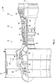
- FIG. 1 illustrates an aircraft assembly 10 having an aircraft fuselage 12 and a gas turbine engine 20, and FIG. 2 schematically illustrates the gas turbine engine 20.
- the gas turbine engine 20 is disclosed herein as a two-spool turbofan that generally incorporates a fan section 22, a compressor section 24, a combustor section 26 and a turbine section 28.
- Alternative engines might include an augmentor section (not shown) among other systems or features.
- the fan section 22 drives air along a bypass flow path B in a bypass duct, while the compressor section 24 drives air along a core flow path C for compression and communication into the combustor section 26 then expansion through the turbine section 28.
- the exemplary engine 20 generally includes a low speed spool 30 and a high speed spool 32 mounted for rotation about an engine central longitudinal axis A relative to an engine static structure 36 via several bearing systems 38. It should be understood that various bearing systems 38 at various locations may alternatively or additionally be provided, and the location of bearing systems 38 may be varied as appropriate to the application.
- the low speed spool 30 generally includes an inner shaft 40 that interconnects a fan 42, a low pressure compressor 44 and a low pressure turbine 46.
- the inner shaft 40 is connected to the fan 42 through a speed change mechanism, which in exemplary gas turbine engine 20 is illustrated as a geared architecture 48 to drive the fan 42 at a lower speed than the low speed spool 30.
- the high speed spool 32 includes an outer shaft 50 that interconnects a high pressure compressor 52 and high pressure turbine 54.
- a combustor 56 is arranged in exemplary gas turbine 20 between the high pressure compressor 52 and the high pressure turbine 54.
- An engine static structure 36 is arranged generally between the high pressure turbine 54 and the low pressure turbine 46.
- the engine static structure 36 further supports bearing systems 38 in the turbine section 28.
- the inner shaft 40 and the outer shaft 50 are concentric and rotate via bearing systems 38 about the engine central longitudinal axis A which is collinear with their longitudinal axes.
- each of the positions of the fan section 22, compressor section 24, combustor section 26, turbine section 28, and fan drive gear system 48 may be varied.
- gear system 48 may be located aft of combustor section 26 or even aft of turbine section 28, and fan section 22 may be positioned forward or aft of the location of gear system 48.
- the engine 20 in one example is a high-bypass geared aircraft engine.
- the engine 20 bypass ratio is greater than about six (6), with an example embodiment being greater than about ten (10)
- the geared architecture 48 is an epicyclical gear train, such as a planetary gear system or other gear system, with a gear reduction ratio of greater than about 2.3
- the low pressure turbine 46 has a pressure ratio that is greater than about five.
- the engine 20 bypass ratio is greater than about ten (10:1)
- the fan diameter is significantly larger than that of the low pressure compressor 44
- the low pressure turbine 46 has a pressure ratio that is greater than about five 5:1.
- Low pressure turbine 46 pressure ratio is pressure measured prior to inlet of low pressure turbine 46 as related to the pressure at the outlet of the low pressure turbine 46 prior to an exhaust nozzle.
- the geared architecture 48 may be an epicycle gear train, such as a planetary gear system or other gear system, with a gear reduction ratio of greater than about 2.3:1. It should be understood, however, that the above parameters are only exemplary of one embodiment of a geared architecture engine and that the present disclosure is applicable to other gas turbine engines including direct drive turbofans.
- the fan section 22 of the engine 20 is designed for a particular flight condition--typically cruise at about 0.8Mach and about 35,000 feet (10,688 meters).
- 'TSFC' Thrust Specific Fuel Consumption
- Low fan pressure ratio is the pressure ratio across the fan blade alone, without a Fan Exit Guide Vane (“FEGV”) system.
- the low fan pressure ratio as disclosed herein according to one non-limiting embodiment is less than about 1.45.
- Low corrected fan tip speed is the actual fan tip speed in ft/sec divided by an industry standard temperature correction of [(Tram °R)/(518.7 °R)] 0.5 .
- the "Low corrected fan tip speed” as disclosed herein according to one non-limiting embodiment is less than about 1150 ft/second (350.5 m/sec).
- the aircraft assembly 10 may include a thermal management system 50 used to control atmospheric conditions for various aircraft systems from the cockpit 52 to avionics 54. These systems may be connected to the thermal management system by typical aircraft mechanicals 56 including tubing, piping 56 and the like.
- the thermal management system 50 may include a heat exchanger 102 illustrated in detail in FIGS. 3-7 and discussed in greater detail below.
- the heat exchanger 102 may utilize a first stream 112 of cold air to cool a second stream 114 of warm air so the warm air may be further utilized in the thermal management system 50.
- the first stream 112 may be obtained from an aircraft bleed 103 off of a compressor 44 in the engine.
- the first stream 112 may be further cooled prior to reaching the heat exchanger 102 via one or more additional heat exchangers in the engine (not shown).
- the first stream 112, containing a certain amount of moisture may develop particles of ice upon reaching the heat exchanger 102, and the ice particles may clog the heat exchanger 102.
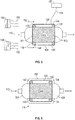
- FIGS. 3-4 illustrate additional details regarding the heat exchanger 102.
- the heat exchanger 102 may be a cross-flow plate-fin heat exchanger and may include a plurality of headers through which relatively warm or hot and cool or cold streams enter and leave the heat exchanger.
- the headers include a first inlet header 104, a second inlet header 106, a first outlet header 108 fluidly connected to the first inlet header, and a second outlet header 110 fluidly connected to the second inlet header.
- the plurality of headers may together direct flow from the first stream 112 and the second stream 114 into and out of a core 116 of the heat exchanger 102.
- the core 116 may include six sides 118-128 and may be shaped like a box. Of course, other configurations are considered to be within the scope of the present disclosure.
- the first inlet header 104 and the first outlet header 108 may respectively cover a first side 118 of the core 116 and an opposing second side 120 of the core 116.
- the second inlet header 106 and second outlet header 110 may respectively cover a third side 122 of the core 116 and an opposing fourth side 124 of the core 116.
- a first cap sheet 130 may cover a fifth side 126 of the core 116 and a second cap sheet 132 may cover an opposing sixth side 128 of the core 116.
- a screen 134 is wrapped around four of the side surfaces of the core 116.
- the screen 134 may cover the first side 118 of the core along with the first core inlet, the second side 120 of the core along with the first core outlet, the fifth side 126 of the core along with the first cap sheet and the sixth side 128 of the core along with the second cap sheet.
- the adjacent sides which are exposed to hot flow for example, the third side 122 of the core along with the second core inlet and the fourth side 124 of the core along with the second core outlet, may not be covered by the screen 134.
- the screen 134 may be continuous and may be a fiber filter or a wire screen.
- the screen 134 may be spaced from the core surface by a plurality of rollers 136-142 distributed about the core.
- the rollers 136-142 may each have a long axis defined by the rotational axis of the respective rollers.
- the rollers may be oriented such that the long axis of each roller extends between the third side 122 of the core and the fourth side 124 of the core.
- the first roller 136 and the fourth roller 142 are disposed between the screen 134 and the fifth side 126 of the core for frictional engagement therebetween.
- the second roller 138 and the third roller 140 are disposed between the screen 134 and the sixth side 128 of the core for frictional engagement therebetween.
- the rollers may frictionally engage the screen so that the screen may move about the core.
- the screen may mate with the rollers in a sprocket and chain type of arrangement rather than in a frictional arrangement.
- the four rollers 136-142 may be respectively positioned proximate one of four corners 144-150 of the core or at intersections between adjacent sides of the core. That is, a first roller 136 may be proximate a first corner 144 of the core, at an intersection of the second side 120 of the core and the fifth side 126 of the core. A second roller 138 may be proximate a second corner 146 of the core, at an intersection of the second side 120 of the core and the sixth side 128 of the core. A third roller 140 may be proximate a third corner 148 of the core, at an intersection of the first side 118 of the core and the sixth side 128 of the core. A fourth roller 142 may be proximate a fourth corner 150 of the core, at an intersection of the first side 118 of the core and the fifth side 126 of the core.
- a motor 129 drives at least one of the rollers. This action moves the screen due to, for example, the frictional engagement between the screen and the at least one of the rollers.
- the motor driven roller would drive the screen due to mechanical interaction therebetween.
- the motor 129 may drive the screen continuously, at a periodic rate that is sufficient to prevent an accumulation of ice on the screen, upon sensing a predetermined amount of ice accumulation, or upon sending various atmospheric conditions indicative of potential ice buildup, such as ambient air temperature, pressure and/or humidity. With this configuration the screen 134, wrapped around the core 116, moves around the core under action of the motor.
- the ice accumulates on a first portion 151 of the screen 134 disposed at the first inlet header 104. As more ice accumulates on the screen 134, the screen may begin to clog.
- the movement of the screen 134 about the heat exchanger 102 may remove or melt the ice before the ice could clog the screen. That is, the screen 134 moves about the core 116, on the rollers, which moves the first portion 151 of the screen 134 away from the first inlet header 104. At the same time, moving the screen 134 brings a second portion 153 of the screen to the first inlet header. From this movement, the first portion 151 of the screen 134, which may be ice clogged, is moved to the first outlet header 108. The first stream 112, warmed by flowing through the core 116, may clear the iced portion 151 of the screen 134 at the first outlet header 108.
- the first stream 112 at the cold outlet 108 may not be sufficient to clear ice from the screen 134.
- the screen may need to be heated using an additional implement. As illustrated in FIG. 5 , additional heating of the screen 134 may be accomplished by passing a second warm flow 152 of air, from a second source 155 of warm air, over the moving screen 134.
- the screen 134 may also or alternatively be heated directly by electrical connectors 154 connected to a source of electric current 157 and connected to the screen 134.
- an enclosure 158 may be provided.
- the enclosure 158 may enclose the screen 134 and core 116 to define a cavity 160 therein. Flow leaking around the screen 134 at the cold inlet 104 may be contained within the cavity 160 and directed to the cold outlet 108.
- This configuration may be applicable to fluids other than air, for example, filtering ice out of cold fuel.
- the screen 134 may cover the first side 118 of the core along with the first core inlet, the second side 120 of the core along with the first core outlet, the third side 122 of the core along with the second core inlet and the fourth side 124 of the core along with the second core outlet.
- the screen 134 does covers neither the fifth side 126 of the core, which has the first cap sheet, nor the sixth side 128 of the core, which has the second cap sheet.
- This configuration may be suitable where the hot stream 114 may be air, and mixing of the hot stream 114 and cold stream 112 may be acceptable.
- the hot stream 114 passes through the screen 134 at the second core inlet, by which the screen is provided with additional heat as the screen moves about the core. This configuration may further melt ice and may prevent ice from forming on the screen.
- rollers 136-142 in the configuration of FIG. 7 may be disposed between the third side 122 of the core and the screen 134, as well as between the fourth side 124 of the core and the screen.
- rollers 136-142 in this configuration may be disposed between the first side 118 of the core and the screen 134, and between the second side 120 of the core and the screen.
- the above disclosure may prevent icing of heat exchangers by filtering ice out of the airstream before ice enters the heat exchanger core.
- the configuration may eliminate or reduce the need for other implements for mitigating heat exchanger icing. This configuration may have minimal impact on the overall performance, weight, and volume of the heat exchanger.
- the above disclosure is directed to a heat exchanger having a moveable screen wrapped around a core, the disclosure may be applicable to any apparatus having a moving a screen around a core.
Landscapes
- Engineering & Computer Science (AREA)
- Mechanical Engineering (AREA)
- Chemical & Material Sciences (AREA)
- Combustion & Propulsion (AREA)
- General Engineering & Computer Science (AREA)
- Physics & Mathematics (AREA)
- Thermal Sciences (AREA)
- Aviation & Aerospace Engineering (AREA)
- Health & Medical Sciences (AREA)
- General Health & Medical Sciences (AREA)
- Pulmonology (AREA)
- Heat-Exchange Devices With Radiators And Conduit Assemblies (AREA)
Abstract
Description
- Exemplary embodiments pertain to a heat exchanger of a gas turbine engine and more particularly, to a heat exchanger with a moveable screen.
- Compact plate-fin heat exchangers may be used in aircraft systems to reject waste heat to a cold airstream. The cold airstream may originate from ambient air and may contain humidity which may cause icing in components, such as heat exchangers, when air is cooled below the freezing point.
- Implements for dealing with icing of heat exchangers may include keeping an airstream above freezing, which may result in a performance detriment. Implements may include oversizing the heat exchanger to manage wall temperatures, minimize ice accumulation and melt accreting ice, which may result in a weight and volume detriment. Implementing bypasses and defrost cycles to periodically melt ice may result in a performance detriment. As such, an alternative implement is desired.
- Disclosed is a heat exchanger for a thermal management system of an aircraft assembly, the heat exchanger comprising: a core including a first side with a first core inlet, a second side that opposes the first side and includes a first core outlet, wherein the first core inlet is in fluid communication with the first core outlet, a third side having a second core inlet and a fourth side that opposes the third side and includes a second core outlet, wherein the second core inlet is in fluid communication with the second core outlet, and a screen wrapped around the core, the screen covering the first core inlet and the first core outlet, and a plurality of rollers disposed between the core and the screen for movably securing the screen to the core, the plurality of rollers engaging the screen and wherein movement of at least one of the plurality of rollers causes the screen to move about the core.
- In addition to the above features, or as an alternative, the heat exchanger includes a motor that drives the at least one roller of the plurality of rollers.
- In addition to the above features, or as an alternative, the heat exchanger is a cross-flow plate-fin heat exchanger, the heat exchanger core comprises a fifth side and an opposing sixth side, wherein the fifth side comprises a first cap sheet and the sixth side comprises a second cap sheet.
- In addition to the above features, or as an alternative, the screen covers the first side of the core, the second side of the core, the fifth side of the core and the sixth side of the core, and wherein the set of rollers includes a first set of rollers disposed between the fifth side of the core and the screen and a second set of rollers disposed between the sixth side of the core and the screen.
- In addition to the above features, or as an alternative, the screen covers the first side of the core, the second side of the core, the third side of the core and the fourth side of the core.
- In addition to the above features, or as an alternative, the set of rollers includes a first set of rollers disposed between the third side of the core and the screen and a second set of rollers disposed between the fourth side of the core and the screen.
- In addition to the above features, or as an alternative, the set of rollers includes a first set of rollers disposed between the first side of the core and the screen and a second set of rollers disposed between the second side of the core and the screen.
- In addition to the above features, or as an alternative, electrical connectors are connected to the screen for transferring electric current to the screen.
- In addition to the above features, or as an alternative, an enclosure encloses the screen and the core, and the enclosure fluidly connects a cavity defined between the enclosure and the core to the first core outlet.
- Further disclosed is an aircraft, comprising: a gas turbine engine operatively coupled to the aircraft, the gas turbine engine comprising a fan, a compressor, a combustor and a turbine; and a thermal management system operatively coupled to the gas turbine engine, the thermal management system including a heat exchanger with one or more of the above disclosed features.
- Further disclosed is a method of moving an ice screen about a core of a heat exchanger, the heat exchanger being operatively coupled to a gas turbine engine, the method comprising: movably securing the ice screen about the core of the heat exchanger, wherein the ice screen covers an inlet and an outlet of the heat exchanger, and moving the ice screen about the core by rotating at least one of a plurality of rollers located between the core and the ice screen.
- In addition to the above features, or as an alternative, the step of moving the ice screen about the core alternatively positions a first portion of the ice screen over a first core inlet disposed at a first side of the core and a first core outlet disposed at a second side of the core, wherein the core is box shaped and the first side of the core opposes the second side of the core.
- The following descriptions should not be considered limiting in any way. With reference to the accompanying drawings, like elements are numbered alike:
-
FIG. 1 is a perspective view of an aircraft; -
FIG. 2 is a partial cross sectional view of a gas turbine engine; -
FIG. 3 is a perspective view of a cross-flow plate-fin heat exchanger; -
FIG. 4 is a perspective view of a cross-flow plate-fin heat exchanger according to an embodiment; -
FIG. 5 is a view of a cross-flow plate-fin heat exchanger according to an embodiment; -
FIG. 6 is a view of a cross-flow plate-fin heat exchanger according to an embodiment; and -
FIG. 7 is a view of a cross-flow plate-fin heat exchanger according to an embodiment. - A detailed description of one or more embodiments of the disclosed apparatus and method are presented herein by way of exemplification and not limitation with reference to the Figures.
-
FIG. 1 illustrates anaircraft assembly 10 having anaircraft fuselage 12 and agas turbine engine 20, andFIG. 2 schematically illustrates thegas turbine engine 20. Thegas turbine engine 20 is disclosed herein as a two-spool turbofan that generally incorporates afan section 22, acompressor section 24, acombustor section 26 and aturbine section 28. Alternative engines might include an augmentor section (not shown) among other systems or features. Thefan section 22 drives air along a bypass flow path B in a bypass duct, while thecompressor section 24 drives air along a core flow path C for compression and communication into thecombustor section 26 then expansion through theturbine section 28. Although depicted as a two-spool turbofan gas turbine engine in the disclosed non-limiting embodiment, it should be understood that the concepts described herein are not limited to use with two-spool turbofans as the teachings may be applied to other types of turbine engines including three-spool architectures. - The
exemplary engine 20 generally includes alow speed spool 30 and ahigh speed spool 32 mounted for rotation about an engine central longitudinal axis A relative to an enginestatic structure 36 viaseveral bearing systems 38. It should be understood thatvarious bearing systems 38 at various locations may alternatively or additionally be provided, and the location ofbearing systems 38 may be varied as appropriate to the application. - The
low speed spool 30 generally includes aninner shaft 40 that interconnects afan 42, alow pressure compressor 44 and alow pressure turbine 46. Theinner shaft 40 is connected to thefan 42 through a speed change mechanism, which in exemplarygas turbine engine 20 is illustrated as a gearedarchitecture 48 to drive thefan 42 at a lower speed than thelow speed spool 30. Thehigh speed spool 32 includes anouter shaft 50 that interconnects ahigh pressure compressor 52 andhigh pressure turbine 54. Acombustor 56 is arranged inexemplary gas turbine 20 between thehigh pressure compressor 52 and thehigh pressure turbine 54. An enginestatic structure 36 is arranged generally between thehigh pressure turbine 54 and thelow pressure turbine 46. The enginestatic structure 36 further supports bearingsystems 38 in theturbine section 28. Theinner shaft 40 and theouter shaft 50 are concentric and rotate viabearing systems 38 about the engine central longitudinal axis A which is collinear with their longitudinal axes. - The core airflow is compressed by the
low pressure compressor 44 then thehigh pressure compressor 52, mixed and burned with fuel in thecombustor 56, then expanded over thehigh pressure turbine 54 andlow pressure turbine 46. Theturbines low speed spool 30 andhigh speed spool 32 in response to the expansion. It will be appreciated that each of the positions of thefan section 22,compressor section 24,combustor section 26,turbine section 28, and fandrive gear system 48 may be varied. For example,gear system 48 may be located aft ofcombustor section 26 or even aft ofturbine section 28, andfan section 22 may be positioned forward or aft of the location ofgear system 48. - The
engine 20 in one example is a high-bypass geared aircraft engine. In a further example, theengine 20 bypass ratio is greater than about six (6), with an example embodiment being greater than about ten (10), the gearedarchitecture 48 is an epicyclical gear train, such as a planetary gear system or other gear system, with a gear reduction ratio of greater than about 2.3 and thelow pressure turbine 46 has a pressure ratio that is greater than about five. In one disclosed embodiment, theengine 20 bypass ratio is greater than about ten (10:1), the fan diameter is significantly larger than that of thelow pressure compressor 44, and thelow pressure turbine 46 has a pressure ratio that is greater than about five 5:1.Low pressure turbine 46 pressure ratio is pressure measured prior to inlet oflow pressure turbine 46 as related to the pressure at the outlet of thelow pressure turbine 46 prior to an exhaust nozzle. The gearedarchitecture 48 may be an epicycle gear train, such as a planetary gear system or other gear system, with a gear reduction ratio of greater than about 2.3:1. It should be understood, however, that the above parameters are only exemplary of one embodiment of a geared architecture engine and that the present disclosure is applicable to other gas turbine engines including direct drive turbofans. - A significant amount of thrust is provided by the bypass flow B due to the high bypass ratio. The
fan section 22 of theengine 20 is designed for a particular flight condition--typically cruise at about 0.8Mach and about 35,000 feet (10,688 meters). The flight condition of 0.8 Mach and 35,000 ft (10,688 meters), with the engine at its best fuel consumption--also known as "bucket cruise Thrust Specific Fuel Consumption ('TSFC')"--is the industry standard parameter of lbm of fuel being burned divided by lbf of thrust the engine produces at that minimum point. "Low fan pressure ratio" is the pressure ratio across the fan blade alone, without a Fan Exit Guide Vane ("FEGV") system. The low fan pressure ratio as disclosed herein according to one non-limiting embodiment is less than about 1.45. "Low corrected fan tip speed" is the actual fan tip speed in ft/sec divided by an industry standard temperature correction of [(Tram °R)/(518.7 °R)]0.5. The "Low corrected fan tip speed" as disclosed herein according to one non-limiting embodiment is less than about 1150 ft/second (350.5 m/sec). - The
aircraft assembly 10 may include athermal management system 50 used to control atmospheric conditions for various aircraft systems from thecockpit 52 toavionics 54. These systems may be connected to the thermal management system bytypical aircraft mechanicals 56 including tubing, piping 56 and the like. Thethermal management system 50 may include aheat exchanger 102 illustrated in detail inFIGS. 3-7 and discussed in greater detail below. Theheat exchanger 102 may utilize afirst stream 112 of cold air to cool asecond stream 114 of warm air so the warm air may be further utilized in thethermal management system 50. Thefirst stream 112 may be obtained from anaircraft bleed 103 off of acompressor 44 in the engine. Thefirst stream 112 may be further cooled prior to reaching theheat exchanger 102 via one or more additional heat exchangers in the engine (not shown). Thefirst stream 112, containing a certain amount of moisture, may develop particles of ice upon reaching theheat exchanger 102, and the ice particles may clog theheat exchanger 102. -
FIGS. 3-4 illustrate additional details regarding theheat exchanger 102. Theheat exchanger 102 may be a cross-flow plate-fin heat exchanger and may include a plurality of headers through which relatively warm or hot and cool or cold streams enter and leave the heat exchanger. The headers include afirst inlet header 104, asecond inlet header 106, afirst outlet header 108 fluidly connected to the first inlet header, and asecond outlet header 110 fluidly connected to the second inlet header. The plurality of headers may together direct flow from thefirst stream 112 and thesecond stream 114 into and out of acore 116 of theheat exchanger 102. - The
core 116 may include six sides 118-128 and may be shaped like a box. Of course, other configurations are considered to be within the scope of the present disclosure. Thefirst inlet header 104 and thefirst outlet header 108 may respectively cover afirst side 118 of thecore 116 and an opposingsecond side 120 of thecore 116. Thesecond inlet header 106 andsecond outlet header 110 may respectively cover athird side 122 of thecore 116 and an opposingfourth side 124 of thecore 116. Afirst cap sheet 130 may cover afifth side 126 of thecore 116 and asecond cap sheet 132 may cover an opposingsixth side 128 of thecore 116. - In one embodiment, a
screen 134 is wrapped around four of the side surfaces of thecore 116. For example, thescreen 134 may cover thefirst side 118 of the core along with the first core inlet, thesecond side 120 of the core along with the first core outlet, thefifth side 126 of the core along with the first cap sheet and thesixth side 128 of the core along with the second cap sheet. The adjacent sides which are exposed to hot flow, for example, thethird side 122 of the core along with the second core inlet and thefourth side 124 of the core along with the second core outlet, may not be covered by thescreen 134. Thescreen 134 may be continuous and may be a fiber filter or a wire screen. - As shown in
Figs. 4-6 , thescreen 134 may be spaced from the core surface by a plurality of rollers 136-142 distributed about the core. The rollers 136-142 may each have a long axis defined by the rotational axis of the respective rollers. The rollers may be oriented such that the long axis of each roller extends between thethird side 122 of the core and thefourth side 124 of the core. Thefirst roller 136 and thefourth roller 142 are disposed between thescreen 134 and thefifth side 126 of the core for frictional engagement therebetween. Thesecond roller 138 and thethird roller 140 are disposed between thescreen 134 and thesixth side 128 of the core for frictional engagement therebetween. With this configuration, the rollers may frictionally engage the screen so that the screen may move about the core. Alternatively, the screen may mate with the rollers in a sprocket and chain type of arrangement rather than in a frictional arrangement. - The four rollers 136-142 may be respectively positioned proximate one of four corners 144-150 of the core or at intersections between adjacent sides of the core. That is, a
first roller 136 may be proximate afirst corner 144 of the core, at an intersection of thesecond side 120 of the core and thefifth side 126 of the core. Asecond roller 138 may be proximate asecond corner 146 of the core, at an intersection of thesecond side 120 of the core and thesixth side 128 of the core. Athird roller 140 may be proximate athird corner 148 of the core, at an intersection of thefirst side 118 of the core and thesixth side 128 of the core. Afourth roller 142 may be proximate afourth corner 150 of the core, at an intersection of thefirst side 118 of the core and thefifth side 126 of the core. - A motor 129 (illustrated schematically) drives at least one of the rollers. This action moves the screen due to, for example, the frictional engagement between the screen and the at least one of the rollers. In an alternative embodiment that includes the sprocket and chain arrangement between the roller and screen, the motor driven roller would drive the screen due to mechanical interaction therebetween. The
motor 129 may drive the screen continuously, at a periodic rate that is sufficient to prevent an accumulation of ice on the screen, upon sensing a predetermined amount of ice accumulation, or upon sending various atmospheric conditions indicative of potential ice buildup, such as ambient air temperature, pressure and/or humidity. With this configuration thescreen 134, wrapped around thecore 116, moves around the core under action of the motor. - The ice accumulates on a
first portion 151 of thescreen 134 disposed at thefirst inlet header 104. As more ice accumulates on thescreen 134, the screen may begin to clog. The movement of thescreen 134 about theheat exchanger 102 may remove or melt the ice before the ice could clog the screen. That is, thescreen 134 moves about thecore 116, on the rollers, which moves thefirst portion 151 of thescreen 134 away from thefirst inlet header 104. At the same time, moving thescreen 134 brings asecond portion 153 of the screen to the first inlet header. From this movement, thefirst portion 151 of thescreen 134, which may be ice clogged, is moved to thefirst outlet header 108. Thefirst stream 112, warmed by flowing through thecore 116, may clear theiced portion 151 of thescreen 134 at thefirst outlet header 108. - Under certain conditions, the
first stream 112 at thecold outlet 108 may not be sufficient to clear ice from thescreen 134. Thus, the screen may need to be heated using an additional implement. As illustrated inFIG. 5 , additional heating of thescreen 134 may be accomplished by passing a secondwarm flow 152 of air, from asecond source 155 of warm air, over the movingscreen 134. Thescreen 134 may also or alternatively be heated directly byelectrical connectors 154 connected to a source of electric current 157 and connected to thescreen 134. - Turning to
FIG. 6 , to minimize leakage of the cold air around thescreen 134 and rollers 136-142, anenclosure 158 may be provided. Theenclosure 158 may enclose thescreen 134 andcore 116 to define acavity 160 therein. Flow leaking around thescreen 134 at thecold inlet 104 may be contained within thecavity 160 and directed to thecold outlet 108. This configuration may be applicable to fluids other than air, for example, filtering ice out of cold fuel. - Turning to
FIG. 7 , thescreen 134 may cover thefirst side 118 of the core along with the first core inlet, thesecond side 120 of the core along with the first core outlet, thethird side 122 of the core along with the second core inlet and thefourth side 124 of the core along with the second core outlet. In this configuration thescreen 134 does covers neither thefifth side 126 of the core, which has the first cap sheet, nor thesixth side 128 of the core, which has the second cap sheet. This configuration may be suitable where thehot stream 114 may be air, and mixing of thehot stream 114 andcold stream 112 may be acceptable. In this configuration thehot stream 114 passes through thescreen 134 at the second core inlet, by which the screen is provided with additional heat as the screen moves about the core. This configuration may further melt ice and may prevent ice from forming on the screen. - The rollers 136-142 in the configuration of
FIG. 7 may be disposed between thethird side 122 of the core and thescreen 134, as well as between thefourth side 124 of the core and the screen. Alternatively the rollers 136-142 in this configuration may be disposed between thefirst side 118 of the core and thescreen 134, and between thesecond side 120 of the core and the screen. - The above disclosure may prevent icing of heat exchangers by filtering ice out of the airstream before ice enters the heat exchanger core. The configuration may eliminate or reduce the need for other implements for mitigating heat exchanger icing. This configuration may have minimal impact on the overall performance, weight, and volume of the heat exchanger. Though the above disclosure is directed to a heat exchanger having a moveable screen wrapped around a core, the disclosure may be applicable to any apparatus having a moving a screen around a core.
- The term "about" is intended to include the degree of error associated with measurement of the particular quantity based upon the equipment available at the time of filing the application.
- The terminology used herein is for the purpose of describing particular embodiments only and is not intended to be limiting of the present disclosure. As used herein, the singular forms "a", "an" and "the" are intended to include the plural forms as well, unless the context clearly indicates otherwise. It will be further understood that the terms "comprises" and/or "comprising," when used in this specification, specify the presence of stated features, integers, steps, operations, elements, and/or components, but do not preclude the presence or addition of one or more other features, integers, steps, operations, element components, and/or groups thereof.
- While the present disclosure has been described with reference to an exemplary embodiment or embodiments, it will be understood by those skilled in the art that various changes may be made and equivalents may be substituted for elements thereof without departing from the scope of the present disclosure. In addition, many modifications may be made to adapt a particular situation or material to the teachings of the present disclosure without departing from the essential scope thereof. Therefore, it is intended that the present disclosure not be limited to the particular embodiment disclosed as the best mode contemplated for carrying out this present disclosure, but that the present disclosure will include all embodiments falling within the scope of the claims.
Claims (12)
- A heat exchanger (102) for a thermal management system (50) of an aircraft assembly, the heat exchanger (102) comprising:a core (116) including a first side (118) with a first core inlet (104), a second side (120) that opposes the first side (118) and includes a first core outlet (108), wherein the first core inlet (104) is in fluid communication with the first core outlet (108), a third side (122) having a second core inlet (106) and a fourth side (124) that opposes the third side (122) and includes a second core outlet (110), wherein the second core inlet (106) is in fluid communication with the second core outlet (110), anda screen (134) wrapped around the core (116), the screen (134) covering the first core inlet (104) and the first core outlet (108), and a plurality of rollers (136, 138, 140, 142) disposed between the core (116) and the screen (134) for movably securing the screen (134) to the core (116), the plurality of rollers (136, 138, 140, 142) engaging the screen (134) and wherein movement of at least one of the plurality of rollers (136, 138, 140, 142) causes the screen (134) to move about the core (116).
- The heat exchanger (102) of claim 1, further comprising a motor (129) that drives the at least one roller (136, 138, 140, 142) of the plurality of rollers.
- The heat exchanger (102) of claim 1 or 2, wherein the heat exchanger (102) is a cross-flow plate-fin heat exchanger, the heat exchanger core (116) comprises a fifth side (126) and an opposing sixth side (128), wherein the fifth side (126) comprises a first cap sheet (130) and the sixth side (128) comprises a second cap sheet (132).
- The heat exchanger (102) of claim 3, wherein the screen (134) covers the first side (118) of the core (116), the second side (120) of the core, the fifth side (126) of the core and the sixth side (128) of the core, and wherein the set of rollers (136, 138, 140, 142) includes a first set of rollers (136, 142) disposed between the fifth side (126) of the core and the screen (134) and a second set of rollers (138, 140) disposed between the sixth side (128) of the core and the screen (134).
- The heat exchanger (102) of claim 3, wherein the screen (134) covers the first side (118) of the core (116), the second side (120) of the core, the third side (122) of the core and the fourth side (124) of the core.
- The heat exchanger (102) of claim 5, wherein the set of rollers (136, 138, 140, 142) includes a first set of rollers (138, 140) disposed between the third side (122) of the core (116) and the screen (134) and a second set of rollers (136, 142) disposed between the fourth side (124) of the core and the screen (134).
- The heat exchanger (102) of claim 5, wherein the set of rollers (136, 138, 140, 142) includes a first set of rollers (140, 142) disposed between the first side (118) of the core (116) and the screen (134) and a second set of rollers (136, 138) disposed between the second side (120) of the core and the screen (134).
- The heat exchanger (102) of any preceding claim, wherein electrical connectors (154) are connected to the screen (134) for transferring electric current to the screen (134).
- The heat exchanger (102) of any preceding claim, wherein an enclosure (158) encloses the screen (134) and the core (116), and the enclosure (158) fluidly connects a cavity (160) defined between the enclosure (158) and the core (116) to the first core outlet (108).
- An aircraft (10), comprising:a gas turbine engine (20) operatively coupled to the aircraft (10), the gas turbine engine (20) comprising a fan (42), a compressor (44, 52), a combustor (56) and a turbine (46, 54); anda thermal management system (50) operatively coupled to the gas turbine engine (20), the thermal management system (50) including a heat exchanger (102) as claimed in any of claims 1 to 9.
- A method of moving an ice screen (134) about a core (116) of a heat exchanger (102), the heat exchanger (102) being operatively coupled to a gas turbine engine (20), the method comprising:movably securing the ice screen (134) about the core (116) of the heat exchanger (102), wherein the ice screen (134) covers an inlet (104) and an outlet (108) of the heat exchanger (102), andmoving the ice screen (134) about the core (116) by rotating at least one of a plurality of rollers (136, 138, 140, 142) located between the core (116) and the ice screen (134).
- The method of claim 11, wherein moving the ice screen (134) about the core (116) alternatively positions a first portion (151) of the ice screen (134) over a first core inlet (104) disposed at a first side (118) of the core (116) and a first core outlet (108) disposed at a second side (120) of the core (116), wherein the core (116) is box shaped and the first side (118) of the core (116) opposes the second side (120) of the core (116).
Applications Claiming Priority (1)
| Application Number | Priority Date | Filing Date | Title |
|---|---|---|---|
| US15/874,274 US11161621B2 (en) | 2018-01-18 | 2018-01-18 | Heat exchanger with moving ice filter |
Publications (2)
| Publication Number | Publication Date |
|---|---|
| EP3514470A1 true EP3514470A1 (en) | 2019-07-24 |
| EP3514470B1 EP3514470B1 (en) | 2021-05-19 |
Family
ID=65138824
Family Applications (1)
| Application Number | Title | Priority Date | Filing Date |
|---|---|---|---|
| EP19152638.3A Active EP3514470B1 (en) | 2018-01-18 | 2019-01-18 | Heat exchanger with moving ice filter |
Country Status (2)
| Country | Link |
|---|---|
| US (1) | US11161621B2 (en) |
| EP (1) | EP3514470B1 (en) |
Families Citing this family (2)
| Publication number | Priority date | Publication date | Assignee | Title |
|---|---|---|---|---|
| FR3126444B1 (en) | 2021-08-26 | 2024-11-29 | Safran Nacelles | Aircraft refrigerant cooling system comprising a safety heating device and method of using such a system |
| US12434845B2 (en) * | 2023-02-16 | 2025-10-07 | The Boeing Company | Modular heat exchanger systems |
Citations (4)
| Publication number | Priority date | Publication date | Assignee | Title |
|---|---|---|---|---|
| US5529593A (en) * | 1994-10-07 | 1996-06-25 | Air Solution Company | Filter screen assembly for use with an air intake unit |
| US5915469A (en) * | 1995-07-16 | 1999-06-29 | Tat Aero Equipment Industries Ltd. | Condenser heat exchanger |
| WO2008010418A1 (en) * | 2006-07-18 | 2008-01-24 | Daikin Industries, Ltd. | Dust collector and air conditioner |
| GB2491123A (en) * | 2011-05-23 | 2012-11-28 | Agco As | Air filtration system |
Family Cites Families (29)
| Publication number | Priority date | Publication date | Assignee | Title |
|---|---|---|---|---|
| US3233391A (en) * | 1962-12-10 | 1966-02-08 | Honeywell Inc | Gas cleaning apparatus |
| US3208234A (en) | 1963-03-01 | 1965-09-28 | Lockheed Aircraft Corp | Air cycle refrigeration system and method |
| US3487620A (en) * | 1968-02-16 | 1970-01-06 | Nicholas Klein | Smoke cleaning apparatus |
| US3675393A (en) * | 1970-02-20 | 1972-07-11 | Pillsbury Co | Dust collecting process |
| US3717978A (en) * | 1971-07-09 | 1973-02-27 | E Osborne | Air filter system |
| US4057105A (en) * | 1976-06-30 | 1977-11-08 | Caterpillar Tractor Co. | Self-cleaning screen assembly for radiators and method |
| DE4140612C1 (en) * | 1991-12-10 | 1993-06-17 | Fa. Carl Freudenberg, 6940 Weinheim, De | |
| JP3268229B2 (en) * | 1996-06-01 | 2002-03-25 | 株式会社トーテクジャパン | Exhaust gas purification device |
| US6152998A (en) * | 1999-03-09 | 2000-11-28 | Federal Air Conditioning Technologies, Inc. | Automatic filter cartridge |
| US20050178734A1 (en) * | 2004-02-12 | 2005-08-18 | Kilmer Michael C. | Filter for use in closed vessels allowing the use of filter media which can be renewed without opening the vessel, and method of using same |
| US7073573B2 (en) * | 2004-06-09 | 2006-07-11 | Honeywell International, Inc. | Decreased hot side fin density heat exchanger |
| CN101583904B (en) * | 2007-01-26 | 2010-09-22 | 松下电器产业株式会社 | Dust capture device and projected image display device |
| US20090113860A1 (en) * | 2007-11-07 | 2009-05-07 | Sithes Edwin F | Low maintenance air cleaning system for welding chambers |
| US8292981B2 (en) * | 2007-11-07 | 2012-10-23 | Oskar Air Products, Inc. | Low maintenance air cleaning system for welding chambers |
| EP2304326B1 (en) * | 2008-01-14 | 2018-09-19 | Core Energy Recovery Solutions Inc. | Cross-pleated membrane cartridges, and method for making cross-pleated membrane cartridges |
| US20110030323A1 (en) * | 2008-05-07 | 2011-02-10 | Vinson Wade D | Discharging air filter |
| US20110067388A1 (en) * | 2009-09-24 | 2011-03-24 | Xiaogang Zhang | Diesel particulate filtration (dpf) system |
| DE102010053923A1 (en) * | 2010-12-09 | 2012-06-14 | Hydac Ag | Fluid Cooler |
| US9151539B2 (en) * | 2011-04-07 | 2015-10-06 | Hamilton Sundstrand Corporation | Heat exchanger having a core angled between two headers |
| US20130193127A1 (en) * | 2012-01-26 | 2013-08-01 | General Electric Company | Combustion turbine inlet anti-icing resistive heating system |
| US9897003B2 (en) | 2012-10-01 | 2018-02-20 | General Electric Company | Apparatus and method of operating a turbine assembly |
| WO2016051608A1 (en) * | 2014-10-01 | 2016-04-07 | Mitsubishi Heavy Industries Compressor Corporation | Plate laminated type heat exchanger |
| WO2016181509A1 (en) * | 2015-05-12 | 2016-11-17 | 三菱電機株式会社 | Corrugated fin-type heat exchanger, refrigeration cycle device, device for producing corrugated fins, and method for producing corrugated fin-type heat exchanger |
| JP2017125633A (en) * | 2016-01-12 | 2017-07-20 | 住友精密工業株式会社 | Heat exchanger |
| US10589208B2 (en) * | 2016-10-05 | 2020-03-17 | Johnson Controls Technology Company | Heat exchanger filter assembly |
| US10487742B2 (en) * | 2016-11-30 | 2019-11-26 | Hamilton Sundstrand Corporation | Method for reducing thermally induced stresses in a heat exchanger |
| US10247494B2 (en) * | 2017-02-10 | 2019-04-02 | Sustainable Energy Solutions, Llc | Method for negating deposits using turbulence |
| US10473226B2 (en) * | 2017-06-12 | 2019-11-12 | Hamilton Sundstrand Corporation | Heat exchanger valves |
| JP2019073055A (en) * | 2017-10-12 | 2019-05-16 | 株式会社デンソー | Filter device |
-
2018
- 2018-01-18 US US15/874,274 patent/US11161621B2/en active Active
-
2019
- 2019-01-18 EP EP19152638.3A patent/EP3514470B1/en active Active
Patent Citations (4)
| Publication number | Priority date | Publication date | Assignee | Title |
|---|---|---|---|---|
| US5529593A (en) * | 1994-10-07 | 1996-06-25 | Air Solution Company | Filter screen assembly for use with an air intake unit |
| US5915469A (en) * | 1995-07-16 | 1999-06-29 | Tat Aero Equipment Industries Ltd. | Condenser heat exchanger |
| WO2008010418A1 (en) * | 2006-07-18 | 2008-01-24 | Daikin Industries, Ltd. | Dust collector and air conditioner |
| GB2491123A (en) * | 2011-05-23 | 2012-11-28 | Agco As | Air filtration system |
Also Published As
| Publication number | Publication date |
|---|---|
| EP3514470B1 (en) | 2021-05-19 |
| US20190217965A1 (en) | 2019-07-18 |
| US11161621B2 (en) | 2021-11-02 |
Similar Documents
| Publication | Publication Date | Title |
|---|---|---|
| EP3406883B1 (en) | Actively-driven bleed source switching | |
| US10626879B2 (en) | Gas turbine engine with mid-compressor bleed | |
| EP3060760B1 (en) | Airfoil with skin core cooling | |
| EP3406882B1 (en) | Active bleed flow modulation | |
| EP3514470B1 (en) | Heat exchanger with moving ice filter | |
| EP4224002B1 (en) | Power takeoff transmission | |
| EP3330515B1 (en) | Gas turbine engine | |
| EP2964927B1 (en) | Gas turbine engine lubrication system | |
| EP3683419B1 (en) | Integrated cooling air boost compressor and fuel pump | |
| EP3502442B1 (en) | Concentric power takeoff transmission | |
| EP3450723B1 (en) | Passively-driven bleed source switching | |
| EP3557029B1 (en) | Intercooled cooling air fleet management system | |
| EP2959149B1 (en) | Gas turbine engine core utilized in both commercial and military engines | |
| EP3656983A1 (en) | Thermal gradient reducing device for gas turbine engine component | |
| EP3754169B1 (en) | High pressure clearance control system for gas turbine engine | |
| EP4332353A1 (en) | Thermal conditioning of flange with secondary flow | |
| EP3825521B1 (en) | System and method for transporting lubricant through a vane | |
| EP3919721B1 (en) | Cooling system for a gas turbine engine | |
| EP3581762B1 (en) | Platform cooling arrangement for a gas turbine engine | |
| EP3348812B1 (en) | Cooled gas turbine engine cooling air with cold air dump | |
| EP3470651A1 (en) | Cooled combustor configuration | |
| EP3650675A1 (en) | Internal heat exchanger system to cool gas turbine engine components |
Legal Events
| Date | Code | Title | Description |
|---|---|---|---|
| PUAI | Public reference made under article 153(3) epc to a published international application that has entered the european phase |
Free format text: ORIGINAL CODE: 0009012 |
|
| STAA | Information on the status of an ep patent application or granted ep patent |
Free format text: STATUS: THE APPLICATION HAS BEEN PUBLISHED |
|
| AK | Designated contracting states |
Kind code of ref document: A1 Designated state(s): AL AT BE BG CH CY CZ DE DK EE ES FI FR GB GR HR HU IE IS IT LI LT LU LV MC MK MT NL NO PL PT RO RS SE SI SK SM TR |
|
| AX | Request for extension of the european patent |
Extension state: BA ME |
|
| STAA | Information on the status of an ep patent application or granted ep patent |
Free format text: STATUS: REQUEST FOR EXAMINATION WAS MADE |
|
| 17P | Request for examination filed |
Effective date: 20200124 |
|
| RBV | Designated contracting states (corrected) |
Designated state(s): AL AT BE BG CH CY CZ DE DK EE ES FI FR GB GR HR HU IE IS IT LI LT LU LV MC MK MT NL NO PL PT RO RS SE SI SK SM TR |
|
| RIC1 | Information provided on ipc code assigned before grant |
Ipc: B01D 46/18 20060101ALI20201012BHEP Ipc: B64D 13/00 20060101ALI20201012BHEP Ipc: F28F 19/00 20060101AFI20201012BHEP Ipc: F28F 19/01 20060101ALI20201012BHEP Ipc: F28D 21/00 20060101ALN20201012BHEP Ipc: F28D 9/00 20060101ALI20201012BHEP |
|
| GRAP | Despatch of communication of intention to grant a patent |
Free format text: ORIGINAL CODE: EPIDOSNIGR1 |
|
| STAA | Information on the status of an ep patent application or granted ep patent |
Free format text: STATUS: GRANT OF PATENT IS INTENDED |
|
| INTG | Intention to grant announced |
Effective date: 20201127 |
|
| RAP1 | Party data changed (applicant data changed or rights of an application transferred) |
Owner name: RAYTHEON TECHNOLOGIES CORPORATION |
|
| GRAS | Grant fee paid |
Free format text: ORIGINAL CODE: EPIDOSNIGR3 |
|
| GRAA | (expected) grant |
Free format text: ORIGINAL CODE: 0009210 |
|
| STAA | Information on the status of an ep patent application or granted ep patent |
Free format text: STATUS: THE PATENT HAS BEEN GRANTED |
|
| AK | Designated contracting states |
Kind code of ref document: B1 Designated state(s): AL AT BE BG CH CY CZ DE DK EE ES FI FR GB GR HR HU IE IS IT LI LT LU LV MC MK MT NL NO PL PT RO RS SE SI SK SM TR |
|
| REG | Reference to a national code |
Ref country code: GB Ref legal event code: FG4D |
|
| REG | Reference to a national code |
Ref country code: CH Ref legal event code: EP |
|
| REG | Reference to a national code |
Ref country code: DE Ref legal event code: R096 Ref document number: 602019004610 Country of ref document: DE |
|
| REG | Reference to a national code |
Ref country code: AT Ref legal event code: REF Ref document number: 1394394 Country of ref document: AT Kind code of ref document: T Effective date: 20210615 |
|
| REG | Reference to a national code |
Ref country code: IE Ref legal event code: FG4D |
|
| REG | Reference to a national code |
Ref country code: LT Ref legal event code: MG9D |
|
| REG | Reference to a national code |
Ref country code: AT Ref legal event code: MK05 Ref document number: 1394394 Country of ref document: AT Kind code of ref document: T Effective date: 20210519 |
|
| REG | Reference to a national code |
Ref country code: NL Ref legal event code: MP Effective date: 20210519 |
|
| PG25 | Lapsed in a contracting state [announced via postgrant information from national office to epo] |
Ref country code: BG Free format text: LAPSE BECAUSE OF FAILURE TO SUBMIT A TRANSLATION OF THE DESCRIPTION OR TO PAY THE FEE WITHIN THE PRESCRIBED TIME-LIMIT Effective date: 20210819 Ref country code: AT Free format text: LAPSE BECAUSE OF FAILURE TO SUBMIT A TRANSLATION OF THE DESCRIPTION OR TO PAY THE FEE WITHIN THE PRESCRIBED TIME-LIMIT Effective date: 20210519 Ref country code: FI Free format text: LAPSE BECAUSE OF FAILURE TO SUBMIT A TRANSLATION OF THE DESCRIPTION OR TO PAY THE FEE WITHIN THE PRESCRIBED TIME-LIMIT Effective date: 20210519 Ref country code: LT Free format text: LAPSE BECAUSE OF FAILURE TO SUBMIT A TRANSLATION OF THE DESCRIPTION OR TO PAY THE FEE WITHIN THE PRESCRIBED TIME-LIMIT Effective date: 20210519 Ref country code: HR Free format text: LAPSE BECAUSE OF FAILURE TO SUBMIT A TRANSLATION OF THE DESCRIPTION OR TO PAY THE FEE WITHIN THE PRESCRIBED TIME-LIMIT Effective date: 20210519 |
|
| PG25 | Lapsed in a contracting state [announced via postgrant information from national office to epo] |
Ref country code: IS Free format text: LAPSE BECAUSE OF FAILURE TO SUBMIT A TRANSLATION OF THE DESCRIPTION OR TO PAY THE FEE WITHIN THE PRESCRIBED TIME-LIMIT Effective date: 20210919 Ref country code: GR Free format text: LAPSE BECAUSE OF FAILURE TO SUBMIT A TRANSLATION OF THE DESCRIPTION OR TO PAY THE FEE WITHIN THE PRESCRIBED TIME-LIMIT Effective date: 20210820 Ref country code: PL Free format text: LAPSE BECAUSE OF FAILURE TO SUBMIT A TRANSLATION OF THE DESCRIPTION OR TO PAY THE FEE WITHIN THE PRESCRIBED TIME-LIMIT Effective date: 20210519 Ref country code: NO Free format text: LAPSE BECAUSE OF FAILURE TO SUBMIT A TRANSLATION OF THE DESCRIPTION OR TO PAY THE FEE WITHIN THE PRESCRIBED TIME-LIMIT Effective date: 20210819 Ref country code: LV Free format text: LAPSE BECAUSE OF FAILURE TO SUBMIT A TRANSLATION OF THE DESCRIPTION OR TO PAY THE FEE WITHIN THE PRESCRIBED TIME-LIMIT Effective date: 20210519 Ref country code: RS Free format text: LAPSE BECAUSE OF FAILURE TO SUBMIT A TRANSLATION OF THE DESCRIPTION OR TO PAY THE FEE WITHIN THE PRESCRIBED TIME-LIMIT Effective date: 20210519 Ref country code: SE Free format text: LAPSE BECAUSE OF FAILURE TO SUBMIT A TRANSLATION OF THE DESCRIPTION OR TO PAY THE FEE WITHIN THE PRESCRIBED TIME-LIMIT Effective date: 20210519 Ref country code: PT Free format text: LAPSE BECAUSE OF FAILURE TO SUBMIT A TRANSLATION OF THE DESCRIPTION OR TO PAY THE FEE WITHIN THE PRESCRIBED TIME-LIMIT Effective date: 20210920 |
|
| PG25 | Lapsed in a contracting state [announced via postgrant information from national office to epo] |
Ref country code: NL Free format text: LAPSE BECAUSE OF FAILURE TO SUBMIT A TRANSLATION OF THE DESCRIPTION OR TO PAY THE FEE WITHIN THE PRESCRIBED TIME-LIMIT Effective date: 20210519 |
|
| PG25 | Lapsed in a contracting state [announced via postgrant information from national office to epo] |
Ref country code: SK Free format text: LAPSE BECAUSE OF FAILURE TO SUBMIT A TRANSLATION OF THE DESCRIPTION OR TO PAY THE FEE WITHIN THE PRESCRIBED TIME-LIMIT Effective date: 20210519 Ref country code: EE Free format text: LAPSE BECAUSE OF FAILURE TO SUBMIT A TRANSLATION OF THE DESCRIPTION OR TO PAY THE FEE WITHIN THE PRESCRIBED TIME-LIMIT Effective date: 20210519 Ref country code: ES Free format text: LAPSE BECAUSE OF FAILURE TO SUBMIT A TRANSLATION OF THE DESCRIPTION OR TO PAY THE FEE WITHIN THE PRESCRIBED TIME-LIMIT Effective date: 20210519 Ref country code: RO Free format text: LAPSE BECAUSE OF FAILURE TO SUBMIT A TRANSLATION OF THE DESCRIPTION OR TO PAY THE FEE WITHIN THE PRESCRIBED TIME-LIMIT Effective date: 20210519 Ref country code: SM Free format text: LAPSE BECAUSE OF FAILURE TO SUBMIT A TRANSLATION OF THE DESCRIPTION OR TO PAY THE FEE WITHIN THE PRESCRIBED TIME-LIMIT Effective date: 20210519 Ref country code: DK Free format text: LAPSE BECAUSE OF FAILURE TO SUBMIT A TRANSLATION OF THE DESCRIPTION OR TO PAY THE FEE WITHIN THE PRESCRIBED TIME-LIMIT Effective date: 20210519 Ref country code: CZ Free format text: LAPSE BECAUSE OF FAILURE TO SUBMIT A TRANSLATION OF THE DESCRIPTION OR TO PAY THE FEE WITHIN THE PRESCRIBED TIME-LIMIT Effective date: 20210519 |
|
| REG | Reference to a national code |
Ref country code: DE Ref legal event code: R097 Ref document number: 602019004610 Country of ref document: DE |
|
| PLBE | No opposition filed within time limit |
Free format text: ORIGINAL CODE: 0009261 |
|
| STAA | Information on the status of an ep patent application or granted ep patent |
Free format text: STATUS: NO OPPOSITION FILED WITHIN TIME LIMIT |
|
| 26N | No opposition filed |
Effective date: 20220222 |
|
| PG25 | Lapsed in a contracting state [announced via postgrant information from national office to epo] |
Ref country code: IS Free format text: LAPSE BECAUSE OF FAILURE TO SUBMIT A TRANSLATION OF THE DESCRIPTION OR TO PAY THE FEE WITHIN THE PRESCRIBED TIME-LIMIT Effective date: 20210919 Ref country code: AL Free format text: LAPSE BECAUSE OF FAILURE TO SUBMIT A TRANSLATION OF THE DESCRIPTION OR TO PAY THE FEE WITHIN THE PRESCRIBED TIME-LIMIT Effective date: 20210519 |
|
| PG25 | Lapsed in a contracting state [announced via postgrant information from national office to epo] |
Ref country code: IT Free format text: LAPSE BECAUSE OF FAILURE TO SUBMIT A TRANSLATION OF THE DESCRIPTION OR TO PAY THE FEE WITHIN THE PRESCRIBED TIME-LIMIT Effective date: 20210519 |
|
| PG25 | Lapsed in a contracting state [announced via postgrant information from national office to epo] |
Ref country code: MC Free format text: LAPSE BECAUSE OF FAILURE TO SUBMIT A TRANSLATION OF THE DESCRIPTION OR TO PAY THE FEE WITHIN THE PRESCRIBED TIME-LIMIT Effective date: 20210519 |
|
| REG | Reference to a national code |
Ref country code: CH Ref legal event code: PL |
|
| REG | Reference to a national code |
Ref country code: BE Ref legal event code: MM Effective date: 20220131 |
|
| PG25 | Lapsed in a contracting state [announced via postgrant information from national office to epo] |
Ref country code: LU Free format text: LAPSE BECAUSE OF NON-PAYMENT OF DUE FEES Effective date: 20220118 |
|
| PG25 | Lapsed in a contracting state [announced via postgrant information from national office to epo] |
Ref country code: BE Free format text: LAPSE BECAUSE OF NON-PAYMENT OF DUE FEES Effective date: 20220131 |
|
| PG25 | Lapsed in a contracting state [announced via postgrant information from national office to epo] |
Ref country code: LI Free format text: LAPSE BECAUSE OF NON-PAYMENT OF DUE FEES Effective date: 20220131 Ref country code: CH Free format text: LAPSE BECAUSE OF NON-PAYMENT OF DUE FEES Effective date: 20220131 |
|
| PG25 | Lapsed in a contracting state [announced via postgrant information from national office to epo] |
Ref country code: IE Free format text: LAPSE BECAUSE OF NON-PAYMENT OF DUE FEES Effective date: 20220118 |
|
| P01 | Opt-out of the competence of the unified patent court (upc) registered |
Effective date: 20230521 |
|
| PG25 | Lapsed in a contracting state [announced via postgrant information from national office to epo] |
Ref country code: MK Free format text: LAPSE BECAUSE OF FAILURE TO SUBMIT A TRANSLATION OF THE DESCRIPTION OR TO PAY THE FEE WITHIN THE PRESCRIBED TIME-LIMIT Effective date: 20210519 Ref country code: CY Free format text: LAPSE BECAUSE OF FAILURE TO SUBMIT A TRANSLATION OF THE DESCRIPTION OR TO PAY THE FEE WITHIN THE PRESCRIBED TIME-LIMIT Effective date: 20210519 |
|
| PG25 | Lapsed in a contracting state [announced via postgrant information from national office to epo] |
Ref country code: HU Free format text: LAPSE BECAUSE OF FAILURE TO SUBMIT A TRANSLATION OF THE DESCRIPTION OR TO PAY THE FEE WITHIN THE PRESCRIBED TIME-LIMIT; INVALID AB INITIO Effective date: 20190118 |
|
| PG25 | Lapsed in a contracting state [announced via postgrant information from national office to epo] |
Ref country code: MT Free format text: LAPSE BECAUSE OF FAILURE TO SUBMIT A TRANSLATION OF THE DESCRIPTION OR TO PAY THE FEE WITHIN THE PRESCRIBED TIME-LIMIT Effective date: 20210519 |
|
| REG | Reference to a national code |
Ref country code: DE Ref legal event code: R081 Ref document number: 602019004610 Country of ref document: DE Owner name: RTX CORPORATION (N.D.GES.D. STAATES DELAWARE),, US Free format text: FORMER OWNER: RAYTHEON TECHNOLOGIES CORPORATION, FARMINGTON, CT, US |
|
| PG25 | Lapsed in a contracting state [announced via postgrant information from national office to epo] |
Ref country code: TR Free format text: LAPSE BECAUSE OF FAILURE TO SUBMIT A TRANSLATION OF THE DESCRIPTION OR TO PAY THE FEE WITHIN THE PRESCRIBED TIME-LIMIT Effective date: 20210519 |
|
| PGFP | Annual fee paid to national office [announced via postgrant information from national office to epo] |
Ref country code: GB Payment date: 20251219 Year of fee payment: 8 |
|
| PGFP | Annual fee paid to national office [announced via postgrant information from national office to epo] |
Ref country code: FR Payment date: 20251217 Year of fee payment: 8 |
|
| PGFP | Annual fee paid to national office [announced via postgrant information from national office to epo] |
Ref country code: DE Payment date: 20251217 Year of fee payment: 8 |