EP3514458A1 - Air conditioner and motor control device - Google Patents
Air conditioner and motor control device Download PDFInfo
- Publication number
- EP3514458A1 EP3514458A1 EP17901346.1A EP17901346A EP3514458A1 EP 3514458 A1 EP3514458 A1 EP 3514458A1 EP 17901346 A EP17901346 A EP 17901346A EP 3514458 A1 EP3514458 A1 EP 3514458A1
- Authority
- EP
- European Patent Office
- Prior art keywords
- motor
- air conditioner
- drive mode
- rotation speed
- speed
- Prior art date
- Legal status (The legal status is an assumption and is not a legal conclusion. Google has not performed a legal analysis and makes no representation as to the accuracy of the status listed.)
- Withdrawn
Links
- 239000003507 refrigerant Substances 0.000 claims abstract description 24
- 230000006835 compression Effects 0.000 claims abstract description 22
- 238000007906 compression Methods 0.000 claims abstract description 22
- 230000007246 mechanism Effects 0.000 claims abstract description 22
- 230000001133 acceleration Effects 0.000 claims description 8
- 230000003247 decreasing effect Effects 0.000 description 9
- 238000001514 detection method Methods 0.000 description 9
- 230000007423 decrease Effects 0.000 description 5
- 230000008859 change Effects 0.000 description 3
- 238000004891 communication Methods 0.000 description 3
- 238000000034 method Methods 0.000 description 3
- 238000012986 modification Methods 0.000 description 3
- 230000004048 modification Effects 0.000 description 3
- 230000008569 process Effects 0.000 description 3
- 230000009467 reduction Effects 0.000 description 3
- 238000005057 refrigeration Methods 0.000 description 3
- 238000004904 shortening Methods 0.000 description 3
- 230000001360 synchronised effect Effects 0.000 description 3
- 239000003990 capacitor Substances 0.000 description 2
- 238000001816 cooling Methods 0.000 description 2
- 238000010586 diagram Methods 0.000 description 2
- 230000000694 effects Effects 0.000 description 2
- 230000006870 function Effects 0.000 description 2
- 238000009499 grossing Methods 0.000 description 2
- 238000010438 heat treatment Methods 0.000 description 2
- 230000007704 transition Effects 0.000 description 2
- 238000004378 air conditioning Methods 0.000 description 1
- 230000005540 biological transmission Effects 0.000 description 1
- 230000005611 electricity Effects 0.000 description 1
- 230000005669 field effect Effects 0.000 description 1
- 230000010349 pulsation Effects 0.000 description 1
- 239000004065 semiconductor Substances 0.000 description 1
Images



Classifications
-
- F—MECHANICAL ENGINEERING; LIGHTING; HEATING; WEAPONS; BLASTING
- F25—REFRIGERATION OR COOLING; COMBINED HEATING AND REFRIGERATION SYSTEMS; HEAT PUMP SYSTEMS; MANUFACTURE OR STORAGE OF ICE; LIQUEFACTION SOLIDIFICATION OF GASES
- F25B—REFRIGERATION MACHINES, PLANTS OR SYSTEMS; COMBINED HEATING AND REFRIGERATION SYSTEMS; HEAT PUMP SYSTEMS
- F25B49/00—Arrangement or mounting of control or safety devices
- F25B49/02—Arrangement or mounting of control or safety devices for compression type machines, plants or systems
- F25B49/025—Motor control arrangements
-
- F—MECHANICAL ENGINEERING; LIGHTING; HEATING; WEAPONS; BLASTING
- F25—REFRIGERATION OR COOLING; COMBINED HEATING AND REFRIGERATION SYSTEMS; HEAT PUMP SYSTEMS; MANUFACTURE OR STORAGE OF ICE; LIQUEFACTION SOLIDIFICATION OF GASES
- F25B—REFRIGERATION MACHINES, PLANTS OR SYSTEMS; COMBINED HEATING AND REFRIGERATION SYSTEMS; HEAT PUMP SYSTEMS
- F25B49/00—Arrangement or mounting of control or safety devices
- F25B49/02—Arrangement or mounting of control or safety devices for compression type machines, plants or systems
- F25B49/022—Compressor control arrangements
-
- F—MECHANICAL ENGINEERING; LIGHTING; HEATING; WEAPONS; BLASTING
- F24—HEATING; RANGES; VENTILATING
- F24F—AIR-CONDITIONING; AIR-HUMIDIFICATION; VENTILATION; USE OF AIR CURRENTS FOR SCREENING
- F24F11/00—Control or safety arrangements
- F24F11/30—Control or safety arrangements for purposes related to the operation of the system, e.g. for safety or monitoring
-
- F—MECHANICAL ENGINEERING; LIGHTING; HEATING; WEAPONS; BLASTING
- F24—HEATING; RANGES; VENTILATING
- F24F—AIR-CONDITIONING; AIR-HUMIDIFICATION; VENTILATION; USE OF AIR CURRENTS FOR SCREENING
- F24F11/00—Control or safety arrangements
- F24F11/70—Control systems characterised by their outputs; Constructional details thereof
- F24F11/80—Control systems characterised by their outputs; Constructional details thereof for controlling the temperature of the supplied air
- F24F11/86—Control systems characterised by their outputs; Constructional details thereof for controlling the temperature of the supplied air by controlling compressors within refrigeration or heat pump circuits
-
- F—MECHANICAL ENGINEERING; LIGHTING; HEATING; WEAPONS; BLASTING
- F25—REFRIGERATION OR COOLING; COMBINED HEATING AND REFRIGERATION SYSTEMS; HEAT PUMP SYSTEMS; MANUFACTURE OR STORAGE OF ICE; LIQUEFACTION SOLIDIFICATION OF GASES
- F25B—REFRIGERATION MACHINES, PLANTS OR SYSTEMS; COMBINED HEATING AND REFRIGERATION SYSTEMS; HEAT PUMP SYSTEMS
- F25B31/00—Compressor arrangements
- F25B31/02—Compressor arrangements of motor-compressor units
- F25B31/026—Compressor arrangements of motor-compressor units with compressor of rotary type
-
- F—MECHANICAL ENGINEERING; LIGHTING; HEATING; WEAPONS; BLASTING
- F25—REFRIGERATION OR COOLING; COMBINED HEATING AND REFRIGERATION SYSTEMS; HEAT PUMP SYSTEMS; MANUFACTURE OR STORAGE OF ICE; LIQUEFACTION SOLIDIFICATION OF GASES
- F25B—REFRIGERATION MACHINES, PLANTS OR SYSTEMS; COMBINED HEATING AND REFRIGERATION SYSTEMS; HEAT PUMP SYSTEMS
- F25B13/00—Compression machines, plants or systems, with reversible cycle
-
- F—MECHANICAL ENGINEERING; LIGHTING; HEATING; WEAPONS; BLASTING
- F25—REFRIGERATION OR COOLING; COMBINED HEATING AND REFRIGERATION SYSTEMS; HEAT PUMP SYSTEMS; MANUFACTURE OR STORAGE OF ICE; LIQUEFACTION SOLIDIFICATION OF GASES
- F25B—REFRIGERATION MACHINES, PLANTS OR SYSTEMS; COMBINED HEATING AND REFRIGERATION SYSTEMS; HEAT PUMP SYSTEMS
- F25B2500/00—Problems to be solved
- F25B2500/12—Sound
-
- F—MECHANICAL ENGINEERING; LIGHTING; HEATING; WEAPONS; BLASTING
- F25—REFRIGERATION OR COOLING; COMBINED HEATING AND REFRIGERATION SYSTEMS; HEAT PUMP SYSTEMS; MANUFACTURE OR STORAGE OF ICE; LIQUEFACTION SOLIDIFICATION OF GASES
- F25B—REFRIGERATION MACHINES, PLANTS OR SYSTEMS; COMBINED HEATING AND REFRIGERATION SYSTEMS; HEAT PUMP SYSTEMS
- F25B2500/00—Problems to be solved
- F25B2500/13—Vibrations
-
- F—MECHANICAL ENGINEERING; LIGHTING; HEATING; WEAPONS; BLASTING
- F25—REFRIGERATION OR COOLING; COMBINED HEATING AND REFRIGERATION SYSTEMS; HEAT PUMP SYSTEMS; MANUFACTURE OR STORAGE OF ICE; LIQUEFACTION SOLIDIFICATION OF GASES
- F25B—REFRIGERATION MACHINES, PLANTS OR SYSTEMS; COMBINED HEATING AND REFRIGERATION SYSTEMS; HEAT PUMP SYSTEMS
- F25B2500/00—Problems to be solved
- F25B2500/27—Problems to be solved characterised by the stop of the refrigeration cycle
-
- F—MECHANICAL ENGINEERING; LIGHTING; HEATING; WEAPONS; BLASTING
- F25—REFRIGERATION OR COOLING; COMBINED HEATING AND REFRIGERATION SYSTEMS; HEAT PUMP SYSTEMS; MANUFACTURE OR STORAGE OF ICE; LIQUEFACTION SOLIDIFICATION OF GASES
- F25B—REFRIGERATION MACHINES, PLANTS OR SYSTEMS; COMBINED HEATING AND REFRIGERATION SYSTEMS; HEAT PUMP SYSTEMS
- F25B2600/00—Control issues
- F25B2600/02—Compressor control
- F25B2600/021—Inverters therefor
-
- F—MECHANICAL ENGINEERING; LIGHTING; HEATING; WEAPONS; BLASTING
- F25—REFRIGERATION OR COOLING; COMBINED HEATING AND REFRIGERATION SYSTEMS; HEAT PUMP SYSTEMS; MANUFACTURE OR STORAGE OF ICE; LIQUEFACTION SOLIDIFICATION OF GASES
- F25B—REFRIGERATION MACHINES, PLANTS OR SYSTEMS; COMBINED HEATING AND REFRIGERATION SYSTEMS; HEAT PUMP SYSTEMS
- F25B2600/00—Control issues
- F25B2600/02—Compressor control
- F25B2600/025—Compressor control by controlling speed
- F25B2600/0253—Compressor control by controlling speed with variable speed
-
- F—MECHANICAL ENGINEERING; LIGHTING; HEATING; WEAPONS; BLASTING
- F25—REFRIGERATION OR COOLING; COMBINED HEATING AND REFRIGERATION SYSTEMS; HEAT PUMP SYSTEMS; MANUFACTURE OR STORAGE OF ICE; LIQUEFACTION SOLIDIFICATION OF GASES
- F25B—REFRIGERATION MACHINES, PLANTS OR SYSTEMS; COMBINED HEATING AND REFRIGERATION SYSTEMS; HEAT PUMP SYSTEMS
- F25B2600/00—Control issues
- F25B2600/15—Control issues during shut down
-
- F—MECHANICAL ENGINEERING; LIGHTING; HEATING; WEAPONS; BLASTING
- F25—REFRIGERATION OR COOLING; COMBINED HEATING AND REFRIGERATION SYSTEMS; HEAT PUMP SYSTEMS; MANUFACTURE OR STORAGE OF ICE; LIQUEFACTION SOLIDIFICATION OF GASES
- F25B—REFRIGERATION MACHINES, PLANTS OR SYSTEMS; COMBINED HEATING AND REFRIGERATION SYSTEMS; HEAT PUMP SYSTEMS
- F25B2700/00—Sensing or detecting of parameters; Sensors therefor
- F25B2700/17—Speeds
- F25B2700/171—Speeds of the compressor
-
- Y—GENERAL TAGGING OF NEW TECHNOLOGICAL DEVELOPMENTS; GENERAL TAGGING OF CROSS-SECTIONAL TECHNOLOGIES SPANNING OVER SEVERAL SECTIONS OF THE IPC; TECHNICAL SUBJECTS COVERED BY FORMER USPC CROSS-REFERENCE ART COLLECTIONS [XRACs] AND DIGESTS
- Y02—TECHNOLOGIES OR APPLICATIONS FOR MITIGATION OR ADAPTATION AGAINST CLIMATE CHANGE
- Y02B—CLIMATE CHANGE MITIGATION TECHNOLOGIES RELATED TO BUILDINGS, e.g. HOUSING, HOUSE APPLIANCES OR RELATED END-USER APPLICATIONS
- Y02B30/00—Energy efficient heating, ventilation or air conditioning [HVAC]
- Y02B30/70—Efficient control or regulation technologies, e.g. for control of refrigerant flow, motor or heating
Definitions
- the present invention relates to an air conditioner and a motor controller.
- Patent Document 1 as listed below describes in Claim 1, as a technique of controlling a motor of a compressor such as in an air conditioner, "the control unit, upon receiving a stop instruction, detects the rotation speed of the motor in operation by the speed detector and decelerates the motor, by the speed changing ratio changer, to a stopping speed at which an amount of torque control by an inverter is equal to or larger than a predetermined value, and then stops the motor at a rotor position specified by the stop position determiner.”
- Patent Document 1 Japanese Patent No. 4265601
- Patent Document 1 fails to particularly describe the relationship between the resonance frequency of the piping connected to the compressor of the air conditioner and the stopping speed.
- vibrations and noises generated by the compressor, piping and the like are increased, depending on the relationship between the resonance frequency and the stopping speed, to cause a problem that the user feels discomfort.
- the present invention has been made in view of the above-identified problems, and is intended to provide an air conditioner and a motor controller that reduce user discomfort due to vibrations and noises at a compressor, piping and the like.
- an air conditioner of the present invention includes: a compressor that has a motor and a compression mechanism driven by the motor; a speed detector that detects a rotation speed of the motor; a drive mode controller that controls a drive mode of the motor; and refrigerant piping that is connected to the compression mechanism and allows a refrigerant to flow therethrough, wherein the drive mode controller, for stopping the motor, decelerates the motor to a rotation speed equal to or lower than a resonance frequency between the compression mechanism and the refrigerant piping.
- the present invention reduces user discomfort due to vibrations and noises at a compressor, piping, and the like.
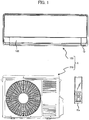
- FIG. 1 is a front view of the air conditioner A.
- the air conditioner A includes an indoor unit 100, an outdoor unit 200, and a remote controller Re.
- the indoor unit 100 is connected with the outdoor unit 200 via refrigerant piping (not shown), to air condition the room in which the indoor unit 100 is installed, by a refrigeration cycle to be described later.
- the indoor unit 100 and the outdoor unit 200 are configured to transmit and receive information to/from each other via a communication cable (not shown).
- the remote controller Re is operated by a user to transmit an infrared signal to a remote control transceiver Q of the indoor unit 100.
- the signal includes a command such as a start request, a change in preset temperature, a timer, a change in operation mode, a stop request, and the like.
- the air conditioner A executes air conditioning operation such as in a cooling mode, in a heating mode, and in a dehumidifying mode.
- the indoor unit 100 transmits data such as room temperature information, humidity information, and electricity charge information from the remote control transceiver Q to the remote controller Re.
- the indoor unit 100 has a vertical louver 102 provided at a front lower end thereof for controlling a vertical air flow direction. The vertical louver 102 is closed when the operation of the air conditioner A is stopped.
- FIG. 2 shows a refrigeration cycle system of the air conditioner A according to the present embodiment.
- the air conditioner A of the present embodiment includes: an indoor heat exchanger 62 that is arranged in the indoor unit 100 (see FIG. 1 ); an outdoor heat exchanger 66 that is arranged in the outdoor unit 200; an expansion valve 64 that is provided in the indoor unit 100 or the outdoor unit 200; a compressor 10 as described above, and refrigerant piping 68 that connects these elements 10, 62, 64, and 66.
- an arrowed line H indicates a flow of the refrigerant during the heating operation
- an arrowed line C indicates a flow of the refrigerant during the cooling operation.
- An indoor-unit fan 61 blows air to the indoor heat exchanger 62, while an outdoor-unit fan 65 blows air to the outdoor heat exchanger 66. Note that a four-way valve for switching a flow of refrigerant, and the like are not shown.
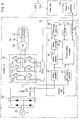
- FIG. 3 is a block diagram of major parts of the air conditioner A.
- the outdoor unit 200 includes the compressor 10, an inverter 20, a driver 21, a rectification circuit 26, a smoothing capacitor 28, and an outdoor unit controller 40.
- the indoor unit 100 includes an indoor unit controller 140.
- the compressor 10 in the outdoor unit 200 includes a motor 12, a compression mechanism 14 that is connected to the motor 12, and a sealed container 16 that houses these in an airtight state.
- the compression mechanism 14 is a one-cylinder rotary compression mechanism.
- the motor 12 is a permanent-magnet three-phase synchronous electric motor.
- the rectifier circuit 26 rectifies the AC voltage supplied from a commercial power supply 30, and the smoothing capacitor 28 smoothes an output voltage of the rectifier circuit 26 to output a DC voltage Edc.
- the DC voltage Edc is inputted to the inverter 20.
- a shunt resistor 24 is inserted between the inverter 20 and the rectifier circuit 26.
- the inverter 20 has switching elements 22a to 22f and freewheeling diodes (having no reference numeral) connected back-to-back. Note that the switching elements 22a to 22f are collectively referred to as a "switching element 22" in some cases.
- an IGBT Insulated Gate Bipolar Transistor
- two switching elements 22 are connected in series to configure upper and lower arms for each phase.
- the switching elements 22a and 22b configure upper and lower arms for a U phase
- the switching elements 22c and 22d configure those for a V phase
- the switching elements 22e and 22f configure those for a W phase.
- the connection point between the upper and lower arms for each phase is connected to the motor 12 of the compressor 10.
- a drive signal supplied via the driver 21 from the outdoor unit controller 40 provides on/off control of the switching element 22. This causes the inverter 20 to modulate the DC voltage Edc with PWM (Pulse Width Modulation), based on the drive signal.
- PWM Pulse Width Modulation
- the outdoor unit controller 40 and the indoor unit controller 140 each include hardware as a general computer such as a CPU (Central Processing Unit), a RAM (Random Access Memory), and a ROM (Read Only Memory), wherein the ROM stores a control program to be executed by the CPU, various data, and the like.
- a CPU Central Processing Unit
- RAM Random Access Memory
- ROM Read Only Memory
- FIG. 3 functions implemented such as by control programs are shown as blocks.
- the outdoor unit controller 40 includes a current calculator 41, a DC voltage detector 42, a speed detector 43, a speed controller 44, a PWM signal generator 46, a drive mode controller 48, a storage unit 51, and a communication unit 52.
- the DC voltage detector 42 detects the DC voltage Edc as described above.
- the current calculator 41 calculates a current value flowing through the inverter 20, based on a voltage drop in the shunt resistor 24.
- the speed detector 43 detects a speed detection value ⁇ 1 of the motor 12 without using any sensor, based on the detection result of the current calculator 41.
- the drive mode controller 48 integrates the speed detection value ⁇ 1 to calculate an electrical angle of the motor 12, multiplies the electrical angle by the number of pole pairs of the motor 12 to calculate a mechanical angle of the motor 12, and outputs a torque command value according to the mechanical angle.
- a load torque generated by the compressor 10 pulsates so as to have a peak at a certain rotation angle. Then, the drive mode controller 48 outputs the torque command value (motor torque command value) that pulsates according to pulsation of the load torque, to reduce vibrations of the compressor 10.
- the speed controller 44 outputs a voltage command value V* that achieves the motor torque according to the torque command value, based on the torque command value outputted from the drive mode controller 48 and the speed detection value ⁇ 1.
- the PWM signal generator 46 outputs a PWM signal according to the voltage command value V*. This PWM signal is buffered by the driver 21 and supplied to each switching element 22.
- the communication unit 52 transmits and receives various commands and information to/from the indoor unit controller 140.
- the storage unit 51 stores various parameters to be used by the drive mode controller 48.
- the storage unit 51 stores one or more resonance frequencies ⁇ p.
- the resonance frequency ⁇ p is a resonance frequency of vibration generated between the compressor 10 in FIG. 2 and the refrigerant piping 68 around the compressor 10.
- the resonance frequency is often a frequency of 20 Hz or less (in other words, a rotation speed of 20 RPS or less).
- the one or more resonance frequencies ⁇ p stored in the storage unit 51 are preferably frequencies of 20 Hz or less.
- FIG. 4 is a flowchart of a stop routine executed in the indoor unit controller 140 of the indoor unit 100 (see FIG. 3 ).
- This routine is activated, for example, when the user initiates stop operation of the air conditioner A using the remote controller Re (see FIG. 1 ).
- the vertical louver 102 of the indoor unit 100 is open and the indoor unit fan 61 is driven for rotation.
- step S102 in FIG. 4 the indoor unit controller 140 transmits a stop command to the outdoor unit controller 40 of the outdoor unit 200. Upon receiving this stop command, the outdoor unit controller 40 executes operation of stopping the motor 12 of the compressor 10. Note that details thereof will be described later.
- step S104 the indoor unit controller 140 closes the vertical louver 102 of the indoor unit 100 (see FIG. 1 ).
- step S106 the indoor unit controller 140 determines whether or not an end notification has been received from the outdoor unit controller 40.
- the "end notification” is a notification that the outdoor unit controller 40 has finished controlling the motor 12 of the compressor 10.
- the processing is on a wait until the result is determined to be "Yes.”
- the indoor unit controller 140 receives the end notification, it proceeds to step S108.
- the indoor unit controller 140 stops the indoor unit fan 61, and ends the processing of this routine.
- the vertical louver 102 is closed in step S104 before the indoor unit fan 61 is stopped in step S108, and the reason for doing this is as follows.
- the compressor 10 is gradually decelerated after the user has initiated stop operation of the air conditioner A using the remote controller Re (see FIG. 1 ), and accordingly it takes some time until the compressor 10 is completely stopped. If the indoor unit fan 61 (see FIG. 2 ) is stopped before the compressor 10 stops, the indoor heat exchanger 62 may have a risk of being overheated or overcooled. Then, the indoor unit fan 61 preferably keeps operating until the compressor 10 is completely stopped.
- step S104 is executed at an early stage so as to close the vertical louver 102. This is because closing the vertical louver 102 allows the user to recognize that the air conditioner A is stopping, even if the indoor unit fan 61 is still in operation.
- FIG. 5 is a flowchart of a timer interruption routine executed in the outdoor unit controller 40 of the outdoor unit 200 (see FIG. 3 ). Upon receiving the above-mentioned stop command from the indoor unit controller 140 (see step S102 in FIG. 4 ), the outdoor unit controller 40 thereafter executes the timer interruption routine at predetermined time intervals.
- step S2 in FIG. 5 the outdoor unit controller 40 determines whether " ⁇ * ⁇ ⁇ p + ⁇ k1" holds true.
- ⁇ k1 is a speed deviation to be described as follows.
- the speed command value ⁇ * is gradually decreased every time a timer interruption occurs.
- the change rate (absolute value of the acceleration) of the speed command value ⁇ * is decreased to increase tracking capability of the torque control by the drive mode controller 48 (see FIG. 3 ) for reducing vibrations and noises.
- the "around the resonance frequency ⁇ p" is more particularly in a range between " ⁇ p + ⁇ k1" and " ⁇ p - ⁇ k2," where ⁇ k1 and ⁇ k2 are the upper and lower speed deviations, respectively.
- the speed deviations ⁇ k1 and ⁇ k2 in the present embodiment are constants to define the range where the speed command value ⁇ * has its decreasing rate (absolute value of acceleration) reduced.
- a speed e.g., speed command value ⁇ *
- the unit of frequency is Hz (Hertz) and the unit of speed is RPS (revolutions per second).
- step S4 the outdoor unit controller 40 opens the expansion valve 64 (see FIG. 2 ). This is for reducing a pressure difference between the suction side and the discharge side of the compressor 10 to reduce vibrations and noises.
- step S6 the outdoor unit controller 40 determines whether " ⁇ * ⁇ ⁇ p - ⁇ k2" holds true.
- step S8 the processing proceeds to step S8, to set a speed command value reduction amount ⁇ to a predetermined value ⁇ 2.
- step S6 the processing proceeds to step S10, to set the speed command value reduction amount ⁇ to a predetermined value ⁇ 1. Note that this step S10 is also executed when the determination result is "No” in step S2 as described above.
- step S12 the outdoor unit controller 40 reduces the speed command value ⁇ * by the speed command value reduction amount ⁇ .
- the predetermined values ⁇ 1 and ⁇ 2 have a relationship of " ⁇ 1 > ⁇ 2.”
- step S14 the outdoor unit controller 40 determines whether or not the speed command value ⁇ * is equal to or less than a predetermined control end speed ⁇ d.
- the control end speed ⁇ d is a speed at which the outdoor unit controller 40 ends controlling the motor 12, and can be "0.” If the control end speed ⁇ d is "0,” the outdoor unit controller 40 executes the torque control by the drive mode controller 48 until the motor 12 stops. Alternatively, the control end speed ⁇ d may be a value exceeding "0.” However, in order to reduce vibrations and noises of the compressor 10, the control end speed ⁇ d preferably satisfies a relationship of " ⁇ d ⁇ ⁇ p - ⁇ k2" for all the resonance frequencies ⁇ p.
- step S14 If the determination result is "No" in step S14, the routine ends. Therefore, as long as the speed command value ⁇ * exceeds the control end speed ⁇ d, the speed command value ⁇ * decreases by the predetermined value ⁇ 1 or ⁇ 2 every time a timer interruption occurs. When the speed command value ⁇ * becomes equal to or less than the control end speed ⁇ d, the determination result is now "Yes” in step S14, and the processing proceeds to step S16.
- step S16 the outdoor unit controller 40 transmits the above-mentioned end notification to the indoor unit controller 140.
- the indoor unit fan 61 is stopped in the indoor unit 100, as described above (in step S108 in FIG. 4 ).
- step S18 any further timer interruption is prohibited. This also prohibits the timer interruption routine from being activated.
- the control end speed ⁇ d having a value exceeding "0”
- the motor 12 is still slightly rotating at this point.
- the rotation speed has a sufficiently small value and therefore the motor 12 stops before long without causing many vibrations and noises.
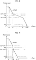
- FIG. 6 is a chart showing an example of transition of the speed detection value ⁇ 1 and the speed command value ⁇ * in the present embodiment.
- the motor 12 is a permanent-magnet three-phase synchronous electric motor, and then the speed detection value ⁇ 1 and the speed command value ⁇ * are substantially equal to each other, as indicated in the drawing.
- the speed command value ⁇ * was constant before time t0 in FIG. 6 , and the outdoor unit controller 40 has received a stop command from the indoor unit controller 140 at time t0.
- the timer interruption routine (see FIG. 5 ) is called after time t0 at predetermined time intervals.
- the speed command value ⁇ * exceeds " ⁇ p + ⁇ k1," and then the speed command value ⁇ * decreases with a slope in proportion to the predetermined value ⁇ 1.
- the speed command value ⁇ * decreases thereafter with a slope in proportion to the predetermined value ⁇ 2.
- the predetermined values ⁇ 1, ⁇ 2 have a relationship of " ⁇ 1 > ⁇ 2" in the present embodiment, and accordingly the speed command value ⁇ * has a smaller decreasing rate (absolute value of acceleration) after time t1 than that before time t1.
- the speed command value ⁇ * decreases at the decreasing rate in proportion to the predetermined value ⁇ 2, the speed command value ⁇ * eventually becomes equal to or less than " ⁇ p - ⁇ k2.” It is assumed that this timing is time t2. As a result, the speed command value ⁇ * has its decreasing rate in proportion to the predetermined value ⁇ 1 again after time t2.
- the outdoor unit controller 40 stops controlling the motor 12, and the motor 12 is decelerated naturally thereafter and stops before long. It is assumed that the motor 12 stops at time t4.
- the drive mode controller 48 in the air conditioner A of the present embodiment decelerates the motor 12 to a rotation speed equal to or lower than the resonance frequency ⁇ p between the compression mechanism 14 and the refrigerant piping 68.
- vibrations and noises of the motor 12 are reduced, and accordingly user discomfort due to vibrations and noises is also reduced.
- the drive mode controller 48 controls the motor 12 so that the absolute value of the acceleration of the motor 12 is smaller than that when the rotation speed falls otherwise. This allows control by the drive mode controller 48 to further reduce vibrations and noises of the motor 12 around the resonance frequency ⁇ p.
- the drive mode controller 48 for stopping the motor 12, decelerates the motor 12 to a rotation speed equal to or lower than the resonance frequency ⁇ p between the compression mechanism 14 and the refrigerant piping 68, while controlling a torque of the motor 12.
- This torque control further reduces vibrations and noises of the motor 12.
- vibrations and noises are further reduced until the motor 12 stops.
- FIG. 7 is a chart showing an example of transition of the speed detection value ⁇ 1 and the speed command value ⁇ * in the present embodiment. It is also assumed in FIG. 7 that the speed command value ⁇ * was constant before time t0, and the outdoor unit controller 40 has received a stop command from the indoor unit controller 140 at time t0. The speed detection value ⁇ 1 and the speed command value ⁇ * before time t1 in FIG. 7 are the same as those in FIG. 6 . Then, once " ⁇ * ⁇ ⁇ p + ⁇ k1" holds true at time t1, the speed command value ⁇ * decreases thereafter with a slope in proportion to the predetermined value ⁇ 2. As ⁇ 2 is larger than ⁇ 1 in the present embodiment, the speed command value ⁇ * has a greater decreasing rate (absolute value of acceleration) after time t1 than that before time t 1.
- the decreasing rate of the speed command value ⁇ * is larger, during the period from time t1 to time t5, than that during the period from time t1 to time t2 in the first embodiment (see FIG. 6 ), likely to have larger vibrations and noises.
- the duration time of vibrations (from time t1 to time t5) is shorter than that in the first embodiment (from time t1 to time t2). This allows for reducing user discomfort, also in the present embodiment, by the same degree as with the first embodiment, or more.
- the drive mode controller 48 in the present embodiment controls the motor 12 so that the absolute value of the acceleration of the motor 12 is larger than that when the rotation speed falls otherwise. This allows for shortening the time during which the motor 12 generates vibrations and noises, to reduce user discomfort.
- the present invention is not limited to the embodiments as described above, and various modifications are possible.
- the embodiments as described above are shown for the purpose of illustrating the present invention, and are not necessarily limited to those having all the components as described.
- some component of an embodiment can be replaced with a component of another embodiment, and some component of an embodiment can be added with a component of another embodiment.
- some component of each embodiment can be deleted, or added/replaced with another component.
- the control lines and information lines shown in the drawings indicate what are considered to be necessary for the description, and do not necessarily show all the necessary control lines and information lines on the product. In practice, it is safe to say that almost all the components are mutually connected. Possible modifications to the above embodiments are as follows, to name but a few.
Landscapes
- Engineering & Computer Science (AREA)
- Mechanical Engineering (AREA)
- General Engineering & Computer Science (AREA)
- Physics & Mathematics (AREA)
- Thermal Sciences (AREA)
- Chemical & Material Sciences (AREA)
- Combustion & Propulsion (AREA)
- Air Conditioning Control Device (AREA)
- Control Of Ac Motors In General (AREA)
Abstract
Description
- The present invention relates to an air conditioner and a motor controller.
-
Patent Document 1 as listed below describes inClaim 1, as a technique of controlling a motor of a compressor such as in an air conditioner, "the control unit, upon receiving a stop instruction, detects the rotation speed of the motor in operation by the speed detector and decelerates the motor, by the speed changing ratio changer, to a stopping speed at which an amount of torque control by an inverter is equal to or larger than a predetermined value, and then stops the motor at a rotor position specified by the stop position determiner." - Patent Document 1: Japanese Patent No.
4265601 - Incidentally,
Patent Document 1 fails to particularly describe the relationship between the resonance frequency of the piping connected to the compressor of the air conditioner and the stopping speed. However, vibrations and noises generated by the compressor, piping and the like are increased, depending on the relationship between the resonance frequency and the stopping speed, to cause a problem that the user feels discomfort. The present invention has been made in view of the above-identified problems, and is intended to provide an air conditioner and a motor controller that reduce user discomfort due to vibrations and noises at a compressor, piping and the like. - In order to solve the above problems, an air conditioner of the present invention includes: a compressor that has a motor and a compression mechanism driven by the motor; a speed detector that detects a rotation speed of the motor; a drive mode controller that controls a drive mode of the motor; and refrigerant piping that is connected to the compression mechanism and allows a refrigerant to flow therethrough, wherein the drive mode controller, for stopping the motor, decelerates the motor to a rotation speed equal to or lower than a resonance frequency between the compression mechanism and the refrigerant piping.
- The present invention reduces user discomfort due to vibrations and noises at a compressor, piping, and the like.
-
-
FIG. 1 shows a schematic configuration of an air conditioner according to a first embodiment of the present invention; -
FIG. 2 illustrates a refrigeration cycle system of the air conditioner; -
FIG. 3 is a block diagram of major parts of the air conditioner; -
FIG. 4 is a flowchart of a stop routine executed in an indoor unit; -
FIG. 5 is a flowchart of a timer interruption routine executed in an outdoor unit; -
FIG. 6 is an operation chart of the first embodiment; and -
FIG. 7 is an operation chart of a second embodiment. - Hereinbelow, a description will be given of a configuration of an air conditioner A according to a first embodiment of the present invention, with reference to
FIG. 1 . Note thatFIG. 1 is a front view of the air conditioner A. As shown inFIG. 1 , the air conditioner A includes anindoor unit 100, anoutdoor unit 200, and a remote controller Re. Theindoor unit 100 is connected with theoutdoor unit 200 via refrigerant piping (not shown), to air condition the room in which theindoor unit 100 is installed, by a refrigeration cycle to be described later. In addition, theindoor unit 100 and theoutdoor unit 200 are configured to transmit and receive information to/from each other via a communication cable (not shown). - The remote controller Re is operated by a user to transmit an infrared signal to a remote control transceiver Q of the
indoor unit 100. The signal includes a command such as a start request, a change in preset temperature, a timer, a change in operation mode, a stop request, and the like. Based on these signals, the air conditioner A executes air conditioning operation such as in a cooling mode, in a heating mode, and in a dehumidifying mode. In addition, theindoor unit 100 transmits data such as room temperature information, humidity information, and electricity charge information from the remote control transceiver Q to the remote controller Re. Theindoor unit 100 has avertical louver 102 provided at a front lower end thereof for controlling a vertical air flow direction. Thevertical louver 102 is closed when the operation of the air conditioner A is stopped. -
FIG. 2 shows a refrigeration cycle system of the air conditioner A according to the present embodiment. As shown inFIG. 2 , the air conditioner A of the present embodiment includes: anindoor heat exchanger 62 that is arranged in the indoor unit 100 (seeFIG. 1 ); anoutdoor heat exchanger 66 that is arranged in theoutdoor unit 200; anexpansion valve 64 that is provided in theindoor unit 100 or theoutdoor unit 200; acompressor 10 as described above, andrefrigerant piping 68 that connects theseelements FIG. 2 , an arrowed line H indicates a flow of the refrigerant during the heating operation, while an arrowed line C indicates a flow of the refrigerant during the cooling operation. An indoor-unit fan 61 blows air to theindoor heat exchanger 62, while an outdoor-unit fan 65 blows air to theoutdoor heat exchanger 66. Note that a four-way valve for switching a flow of refrigerant, and the like are not shown. -
FIG. 3 is a block diagram of major parts of the air conditioner A. InFIG. 3 , theoutdoor unit 200 includes thecompressor 10, aninverter 20, adriver 21, arectification circuit 26, asmoothing capacitor 28, and anoutdoor unit controller 40. In addition, theindoor unit 100 includes anindoor unit controller 140. Further, thecompressor 10 in theoutdoor unit 200 includes amotor 12, acompression mechanism 14 that is connected to themotor 12, and a sealedcontainer 16 that houses these in an airtight state. Note that in the present embodiment, thecompression mechanism 14 is a one-cylinder rotary compression mechanism. Themotor 12 is a permanent-magnet three-phase synchronous electric motor. - In the
outdoor unit 200, therectifier circuit 26 rectifies the AC voltage supplied from acommercial power supply 30, and thesmoothing capacitor 28 smoothes an output voltage of therectifier circuit 26 to output a DC voltage Edc. The DC voltage Edc is inputted to theinverter 20. In addition, ashunt resistor 24 is inserted between theinverter 20 and therectifier circuit 26. Theinverter 20 has switchingelements 22a to 22f and freewheeling diodes (having no reference numeral) connected back-to-back. Note that theswitching elements 22a to 22f are collectively referred to as a "switching element 22" in some cases. In the present embodiment, an IGBT (Insulated Gate Bipolar Transistor) is used for each of these switching elements. - In the
inverter 20, two switching elements 22 are connected in series to configure upper and lower arms for each phase. In the example inFIG. 3 , theswitching elements switching elements switching elements motor 12 of thecompressor 10. A drive signal supplied via thedriver 21 from theoutdoor unit controller 40 provides on/off control of the switching element 22. This causes theinverter 20 to modulate the DC voltage Edc with PWM (Pulse Width Modulation), based on the drive signal. - The
outdoor unit controller 40 and theindoor unit controller 140 each include hardware as a general computer such as a CPU (Central Processing Unit), a RAM (Random Access Memory), and a ROM (Read Only Memory), wherein the ROM stores a control program to be executed by the CPU, various data, and the like. Within theoutdoor unit controller 40 inFIG. 3 , functions implemented such as by control programs are shown as blocks. - That is, the
outdoor unit controller 40 includes acurrent calculator 41, aDC voltage detector 42, aspeed detector 43, aspeed controller 44, aPWM signal generator 46, adrive mode controller 48, astorage unit 51, and acommunication unit 52. TheDC voltage detector 42 detects the DC voltage Edc as described above. Thecurrent calculator 41 calculates a current value flowing through theinverter 20, based on a voltage drop in theshunt resistor 24. - The
speed detector 43 detects a speed detection value ω1 of themotor 12 without using any sensor, based on the detection result of thecurrent calculator 41. Thedrive mode controller 48 integrates the speed detection value ω1 to calculate an electrical angle of themotor 12, multiplies the electrical angle by the number of pole pairs of themotor 12 to calculate a mechanical angle of themotor 12, and outputs a torque command value according to the mechanical angle. A load torque generated by thecompressor 10 pulsates so as to have a peak at a certain rotation angle. Then, thedrive mode controller 48 outputs the torque command value (motor torque command value) that pulsates according to pulsation of the load torque, to reduce vibrations of thecompressor 10. - The
speed controller 44 outputs a voltage command value V* that achieves the motor torque according to the torque command value, based on the torque command value outputted from thedrive mode controller 48 and the speed detection value ω1. ThePWM signal generator 46 outputs a PWM signal according to the voltage command value V*. This PWM signal is buffered by thedriver 21 and supplied to each switching element 22. - The
communication unit 52 transmits and receives various commands and information to/from theindoor unit controller 140. Thestorage unit 51 stores various parameters to be used by thedrive mode controller 48. In particular, thestorage unit 51 stores one or more resonance frequencies ωp. Here, the resonance frequency ωp is a resonance frequency of vibration generated between thecompressor 10 inFIG. 2 and therefrigerant piping 68 around thecompressor 10. When the rotation speed of thecompressor 10 comes around the resonance frequency ωp, vibrations and noises generated by thecompressor 10 and therefrigerant piping 68 tend to be large. Note that in the one-cylinder rotary compressor 10, the resonance frequency is often a frequency of 20 Hz or less (in other words, a rotation speed of 20 RPS or less). Then, the one or more resonance frequencies ωp stored in thestorage unit 51 are preferably frequencies of 20 Hz or less. -
FIG. 4 is a flowchart of a stop routine executed in theindoor unit controller 140 of the indoor unit 100 (seeFIG. 3 ). This routine is activated, for example, when the user initiates stop operation of the air conditioner A using the remote controller Re (seeFIG. 1 ). At the time of the stop operation being initiated, thevertical louver 102 of the indoor unit 100 (seeFIG. 1 ) is open and theindoor unit fan 61 is driven for rotation. - In step S102 in
FIG. 4 , theindoor unit controller 140 transmits a stop command to theoutdoor unit controller 40 of theoutdoor unit 200. Upon receiving this stop command, theoutdoor unit controller 40 executes operation of stopping themotor 12 of thecompressor 10. Note that details thereof will be described later. - Next, in step S104, the
indoor unit controller 140 closes thevertical louver 102 of the indoor unit 100 (seeFIG. 1 ). Next, in step S106, theindoor unit controller 140 determines whether or not an end notification has been received from theoutdoor unit controller 40. Here, the "end notification" is a notification that theoutdoor unit controller 40 has finished controlling themotor 12 of thecompressor 10. As will be described in detail later, when theoutdoor unit controller 40 outputs an end notification, themotor 12 is stopped or in a state of immediately being stopped. In step S106, the processing is on a wait until the result is determined to be "Yes." Once theindoor unit controller 140 receives the end notification, it proceeds to step S108. Here, theindoor unit controller 140 stops theindoor unit fan 61, and ends the processing of this routine. - In the stop routine, the
vertical louver 102 is closed in step S104 before theindoor unit fan 61 is stopped in step S108, and the reason for doing this is as follows. In the present embodiment, thecompressor 10 is gradually decelerated after the user has initiated stop operation of the air conditioner A using the remote controller Re (seeFIG. 1 ), and accordingly it takes some time until thecompressor 10 is completely stopped. If the indoor unit fan 61 (seeFIG. 2 ) is stopped before thecompressor 10 stops, theindoor heat exchanger 62 may have a risk of being overheated or overcooled. Then, theindoor unit fan 61 preferably keeps operating until thecompressor 10 is completely stopped. - However, if the operation of the
indoor unit fan 61 is simply continued, the user may have a doubt. The reason is that if theindoor unit fan 61 continues operation even though the user has initiated stop operation on the remote controller Re, the stop operation seems to be ignored. Then, in the present embodiment, once the stop routine (seeFIG. 4 ) is activated, step S104 is executed at an early stage so as to close thevertical louver 102. This is because closing thevertical louver 102 allows the user to recognize that the air conditioner A is stopping, even if theindoor unit fan 61 is still in operation. -
FIG. 5 is a flowchart of a timer interruption routine executed in theoutdoor unit controller 40 of the outdoor unit 200 (seeFIG. 3 ). Upon receiving the above-mentioned stop command from the indoor unit controller 140 (see step S102 inFIG. 4 ), theoutdoor unit controller 40 thereafter executes the timer interruption routine at predetermined time intervals. - In step S2 in
FIG. 5 , theoutdoor unit controller 40 determines whether "ω* ≤ ωp + ωk1" holds true. Here, ωk1 is a speed deviation to be described as follows. In the present embodiment, the speed command value ω* is gradually decreased every time a timer interruption occurs. However, when the speed command value ω* comes around the resonance frequency ωp, the change rate (absolute value of the acceleration) of the speed command value ω* is decreased to increase tracking capability of the torque control by the drive mode controller 48 (seeFIG. 3 ) for reducing vibrations and noises. - Here, the "around the resonance frequency ωp" is more particularly in a range between "ωp + ωk1" and "ωp - ωk2," where ωk1 and ωk2 are the upper and lower speed deviations, respectively. In this manner, the speed deviations ωk1 and ωk2 in the present embodiment are constants to define the range where the speed command value ω* has its decreasing rate (absolute value of acceleration) reduced. Note that when a speed (e.g., speed command value ω*) is added to, subtracted from, or compared with a frequency (e.g., resonance frequency wp), the unit of frequency is Hz (Hertz) and the unit of speed is RPS (revolutions per second).
- If the determination result is "Yes" in step S2 in
FIG. 5 , the processing proceeds to step S4. Here, theoutdoor unit controller 40 opens the expansion valve 64 (seeFIG. 2 ). This is for reducing a pressure difference between the suction side and the discharge side of thecompressor 10 to reduce vibrations and noises. Next, in step S6, theoutdoor unit controller 40 determines whether "ω* ≥ ωp - ωk2" holds true. Here, if the determination result is "Yes," the processing proceeds to step S8, to set a speed command value reduction amount Δω to a predetermined value Δω2. - In contrast, if the determination result is "No" in step S6, the processing proceeds to step S10, to set the speed command value reduction amount Δω to a predetermined value Δω1. Note that this step S10 is also executed when the determination result is "No" in step S2 as described above. Next, in step S12, the
outdoor unit controller 40 reduces the speed command value ω* by the speed command value reduction amount Δω. Here, in the present embodiment, the predetermined values Δω1 and Δω2 have a relationship of "Δω1 > Δω2." - Next, in step S14, the
outdoor unit controller 40 determines whether or not the speed command value ω* is equal to or less than a predetermined control end speed ωd. Here, the control end speed ωd is a speed at which theoutdoor unit controller 40 ends controlling themotor 12, and can be "0." If the control end speed ωd is "0," theoutdoor unit controller 40 executes the torque control by thedrive mode controller 48 until themotor 12 stops. Alternatively, the control end speed ωd may be a value exceeding "0." However, in order to reduce vibrations and noises of thecompressor 10, the control end speed ωd preferably satisfies a relationship of "ωd ≤ ωp - ωk2" for all the resonance frequencies ωp. - If the determination result is "No" in step S14, the routine ends. Therefore, as long as the speed command value ω* exceeds the control end speed ωd, the speed command value ω* decreases by the predetermined value Δω1 or Δω2 every time a timer interruption occurs. When the speed command value ω* becomes equal to or less than the control end speed ωd, the determination result is now "Yes" in step S14, and the processing proceeds to step S16.
- In step S16, the
outdoor unit controller 40 transmits the above-mentioned end notification to theindoor unit controller 140. As a result, theindoor unit fan 61 is stopped in theindoor unit 100, as described above (in step S108 inFIG. 4 ). Next, in step S18, any further timer interruption is prohibited. This also prohibits the timer interruption routine from being activated. In the case of the control end speed ωd having a value exceeding "0," themotor 12 is still slightly rotating at this point. However, the rotation speed has a sufficiently small value and therefore themotor 12 stops before long without causing many vibrations and noises. -
FIG. 6 is a chart showing an example of transition of the speed detection value ω1 and the speed command value ω* in the present embodiment. Note that themotor 12 is a permanent-magnet three-phase synchronous electric motor, and then the speed detection value ω1 and the speed command value ω* are substantially equal to each other, as indicated in the drawing. It is assumed that the speed command value ω* was constant before time t0 inFIG. 6 , and theoutdoor unit controller 40 has received a stop command from theindoor unit controller 140 at time t0. As a result, the timer interruption routine (seeFIG. 5 ) is called after time t0 at predetermined time intervals. - At time t0, the speed command value ω* exceeds "ωp + ωk1," and then the speed command value ω* decreases with a slope in proportion to the predetermined value Δω1. Once "ω* ≤ ωp + wk1" holds true at time t1, the speed command value ω* decreases thereafter with a slope in proportion to the predetermined value Δω2. As described above, the predetermined values Δω1, Δω2 have a relationship of "Δω1 > Δω2" in the present embodiment, and accordingly the speed command value ω* has a smaller decreasing rate (absolute value of acceleration) after time t1 than that before time t1.
- As described above, when the speed command value ω* decreases at the decreasing rate in proportion to the predetermined value Δω2, the speed command value ω* eventually becomes equal to or less than "ωp - ωk2." It is assumed that this timing is time t2. As a result, the speed command value ω* has its decreasing rate in proportion to the predetermined value Δω1 again after time t2. When the speed command value ω* reaches the control end speed ωd at time t3, the
outdoor unit controller 40 stops controlling themotor 12, and themotor 12 is decelerated naturally thereafter and stops before long. It is assumed that themotor 12 stops at time t4. - As described above, when stopping the
motor 12, thedrive mode controller 48 in the air conditioner A of the present embodiment decelerates themotor 12 to a rotation speed equal to or lower than the resonance frequency ωp between thecompression mechanism 14 and therefrigerant piping 68. As a result, vibrations and noises of themotor 12 are reduced, and accordingly user discomfort due to vibrations and noises is also reduced. - In addition, when the rotation speed of the
motor 12 falls within a predetermined range between "ωp + ωk1" and "ωp - ωk2" centered around the resonance frequency ωp, thedrive mode controller 48 controls themotor 12 so that the absolute value of the acceleration of themotor 12 is smaller than that when the rotation speed falls otherwise. This allows control by thedrive mode controller 48 to further reduce vibrations and noises of themotor 12 around the resonance frequency ωp. - Further, the
drive mode controller 48, for stopping themotor 12, decelerates themotor 12 to a rotation speed equal to or lower than the resonance frequency ωp between thecompression mechanism 14 and therefrigerant piping 68, while controlling a torque of themotor 12. This torque control further reduces vibrations and noises of themotor 12. Additionally, with the configuration in which themotor 12 is decelerated to a rotation speed of zero, while the torque of themotor 12 is controlled, vibrations and noises are further reduced until themotor 12 stops. - Next, a description will be given of an air conditioner according to a second embodiment of the present invention. The hardware configuration and program contents of the air conditioner according to the second embodiment are the same as those of the first embodiment (
FIGS. 1 to 5 ). However, in the present embodiment, predetermined values Δω1, Δω2 (seeFIG. 5 ) have a relationship of "Δω2 > Δω1." That is, the magnitude relation is opposite to that in the first embodiment. -
FIG. 7 is a chart showing an example of transition of the speed detection value ω1 and the speed command value ω* in the present embodiment. It is also assumed inFIG. 7 that the speed command value ω* was constant before time t0, and theoutdoor unit controller 40 has received a stop command from theindoor unit controller 140 at time t0. The speed detection value ω1 and the speed command value ω* before time t1 inFIG. 7 are the same as those inFIG. 6 . Then, once "ω* ≤ ωp + ωk1" holds true at time t1, the speed command value ω* decreases thereafter with a slope in proportion to the predetermined value Δω2. As Δω2 is larger than Δω1 in the present embodiment, the speed command value ω* has a greater decreasing rate (absolute value of acceleration) after time t1 than that beforetime t 1. - Once "ωd ≤ ωp - ωk2" holds true at time t5, the speed command value ω* has its decreasing rate in proportion to the predetermined value Δω1 again. Then, when the speed command value ω* reaches the control end speed ωd at time t6, the
outdoor unit controller 40 stops controlling themotor 12, and themotor 12 is decelerated naturally thereafter and stops before long. It is assumed that themotor 12 stops at time t7. - When vibrations and noises are generated by the
compressor 10 and therefrigerant piping 68, the user feels discomfort at a level expressed roughly as a function of "(the magnitude of vibrations and noises) × (duration time)." Then, there can be two ways to reduce discomfort: "reducing the magnitude of vibrations and noises" and "shortening the duration time." The first embodiment as described above is intended to reduce discomfort by "reducing the magnitude of vibrations and noises." In contrast, the present embodiment is intended to reduce discomfort by "shortening the duration time." - In the present embodiment, the decreasing rate of the speed command value ω* is larger, during the period from time t1 to time t5, than that during the period from time t1 to time t2 in the first embodiment (see
FIG. 6 ), likely to have larger vibrations and noises. However, in the present embodiment, the duration time of vibrations (from time t1 to time t5) is shorter than that in the first embodiment (from time t1 to time t2). This allows for reducing user discomfort, also in the present embodiment, by the same degree as with the first embodiment, or more. - As described above, when the rotation speed of the
motor 12 falls within the predetermined range between "ωp + ωk1" and "ωp - ωk2" centered around the resonance frequency ωp, thedrive mode controller 48 in the present embodiment controls themotor 12 so that the absolute value of the acceleration of themotor 12 is larger than that when the rotation speed falls otherwise. This allows for shortening the time during which themotor 12 generates vibrations and noises, to reduce user discomfort. - The present invention is not limited to the embodiments as described above, and various modifications are possible. The embodiments as described above are shown for the purpose of illustrating the present invention, and are not necessarily limited to those having all the components as described. In addition, some component of an embodiment can be replaced with a component of another embodiment, and some component of an embodiment can be added with a component of another embodiment. Further, some component of each embodiment can be deleted, or added/replaced with another component. Furthermore, the control lines and information lines shown in the drawings indicate what are considered to be necessary for the description, and do not necessarily show all the necessary control lines and information lines on the product. In practice, it is safe to say that almost all the components are mutually connected. Possible modifications to the above embodiments are as follows, to name but a few.
- (1) In steps S2, S6, and S14 in the above embodiments, the speed detection value ω1 may be applied instead of the speed command value ω*. That is, it may respectively be determined in steps S2, S6, and S14 whether or not "ω1 ≤ ωp + ωk1," "ω1 ≥ ωp - ωk2," and "ω1 ≤ ωd" hold true.
- (2) In the above embodiments, the "one-cylinder rotary compression mechanism" is applied as the
compression mechanism 14, but the type of thecompression mechanism 14, the number of cylinders, and the like may be appropriately changed. In the above embodiments, the "permanent-magnet three-phase synchronous electric motor" is applied as themotor 12, but the type of themotor 12 may also be changed as appropriate. In the above embodiments, examples are shown to have the IGBT applied as the switching element 22, but a MOSFET (Metal-Oxide-Semiconductor Field-Effect Transistor) or the like may be applied as the switching element 22. - (3) The hardware of the
outdoor unit controller 40 and the indoor unit controller 140 (seeFIG. 3 ) in the above embodiments are implemented with general computers, and accordingly the programs and the like inFIGS. 4 and5 may be stored in a storage medium, or distributed via a transmission path. - (4) The processes shown in
FIGS. 4 and5 have been described as software processes using programs in the above embodiments, but a part or all of them may be replaced with hardware processes using an ASIC (Application Specific Integrated Circuit), an FPGA (Field-Programmable Gate Array), or the like. -
- 10
- Compressor
- 12
- Motor
- 14
- Compression mechanism
- 43
- Speed detector
- 44
- Speed controller
- 48
- Drive mode controller
- 68
- Refrigerant piping
- Ωp
- Resonance frequency
- A
- Air conditioner
Claims (6)
- An air conditioner comprising:a compressor that has a motor and a compression mechanism driven by the motor;a speed detector that detects a rotation speed of the motor;a drive mode controller that controls a drive mode of the motor; andrefrigerant piping that is connected to the compression mechanism and allows a refrigerant to flow therethrough,wherein the drive mode controller, for stopping the motor, decelerates the motor to a rotation speed equal to or lower than a resonance frequency between the compression mechanism and the refrigerant piping.
- The air conditioner according to claim 1, wherein
when the rotation speed of the motor falls within a predetermined range centered around the resonance frequency, the drive mode controller controls the motor so that the absolute value of the acceleration of the motor is smaller than that when the rotation speed falls otherwise. - The air conditioner according to claim 1, wherein
when the rotation speed of the motor falls within a predetermined range centered around the resonance frequency, the drive mode controller controls the motor so that the absolute value of the acceleration of the motor is larger than that when the rotation speed falls otherwise. - The air conditioner according to any one of claims 1 to 3, wherein
the drive mode controller, for stopping the motor, decelerates the motor to a rotation speed equal to or lower than the resonance frequency between the compression mechanism and the refrigerant piping, while controlling a torque of the motor. - The air conditioner according to claim 4, wherein
the drive mode controller, for stopping the motor, decelerates the motor to a rotation speed of zero, while controlling a torque of the motor. - A motor controller comprising:a speed detector that detects a rotation speed of the motor; anda drive mode controller that controls a drive mode of the motor,wherein the motor drives a compression mechanism in a compressor of an air conditioner, wherein the compression mechanism is connected to refrigerant piping that allows a refrigerant to flow therethrough, and
the drive mode controller, for stopping the motor, decelerates the motor to a rotation speed equal to or lower than a resonance frequency between the compression mechanism and the refrigerant piping.
Applications Claiming Priority (1)
| Application Number | Priority Date | Filing Date | Title |
|---|---|---|---|
| PCT/JP2017/042374 WO2019102611A1 (en) | 2017-11-27 | 2017-11-27 | Air conditioner and motor control device |
Publications (2)
| Publication Number | Publication Date |
|---|---|
| EP3514458A1 true EP3514458A1 (en) | 2019-07-24 |
| EP3514458A4 EP3514458A4 (en) | 2020-01-01 |
Family
ID=64480612
Family Applications (1)
| Application Number | Title | Priority Date | Filing Date |
|---|---|---|---|
| EP17901346.1A Withdrawn EP3514458A4 (en) | 2017-11-27 | 2017-11-27 | Air conditioner and motor control device |
Country Status (7)
| Country | Link |
|---|---|
| US (1) | US10571178B2 (en) |
| EP (1) | EP3514458A4 (en) |
| JP (1) | JP6431648B1 (en) |
| KR (1) | KR102107136B1 (en) |
| CN (1) | CN110100136A (en) |
| TW (1) | TWI663333B (en) |
| WO (1) | WO2019102611A1 (en) |
Families Citing this family (9)
| Publication number | Priority date | Publication date | Assignee | Title |
|---|---|---|---|---|
| KR102067447B1 (en) * | 2018-01-25 | 2020-01-20 | 삼성전자주식회사 | Air conditioner and control method thereof |
| CN108418214A (en) * | 2018-03-28 | 2018-08-17 | 国网江苏省电力有限公司南京供电分公司 | A kind of power grid adjusting method based on convertible frequency air-conditioner load |
| CN110617562A (en) * | 2019-09-12 | 2019-12-27 | 成都仙德科技有限公司 | Vibration suppression method for portable acoustic energy air conditioner |
| CN111678240B (en) * | 2020-06-18 | 2021-11-30 | 重庆美的通用制冷设备有限公司 | Operation control method of air conditioner, air conditioner and readable storage medium |
| JP2022040447A (en) * | 2020-08-31 | 2022-03-11 | パナソニックIpマネジメント株式会社 | Blower and range hood having blower |
| CN112413689A (en) * | 2020-12-08 | 2021-02-26 | 珠海格力电器股份有限公司 | Control method and device of refrigeration integrated cooker, processor and refrigeration integrated cooker system |
| CN112648765B (en) * | 2020-12-15 | 2022-04-12 | 美的威灵电机技术(上海)有限公司 | Refrigeration device |
| US20230019279A1 (en) * | 2021-07-16 | 2023-01-19 | Haier Us Appliance Solutions, Inc. | System and method for operating a variable speed compressor of an air conditioner unit |
| US20230025205A1 (en) * | 2021-07-20 | 2023-01-26 | Haier Us Appliance Solutions, Inc. | System and method for operating a variable speed compressor of an air conditioner unit |
Family Cites Families (13)
| Publication number | Priority date | Publication date | Assignee | Title |
|---|---|---|---|---|
| KR100301500B1 (en) * | 1998-11-28 | 2001-09-22 | 구자홍 | Resonance frequency control apparatus and method for inverter refrigerator |
| CN100412464C (en) * | 2003-03-17 | 2008-08-20 | 松下电器产业株式会社 | air conditioner |
| JP4027273B2 (en) * | 2003-06-19 | 2007-12-26 | 松下電器産業株式会社 | Air conditioner |
| EP1501186B1 (en) * | 2003-07-18 | 2018-08-22 | III Holdings 10, LLC | Motor driving apparatus |
| US20060198744A1 (en) | 2005-03-03 | 2006-09-07 | Carrier Corporation | Skipping frequencies for variable speed controls |
| JP2012110070A (en) * | 2010-11-15 | 2012-06-07 | Panasonic Corp | Air conditioner |
| JP2012110077A (en) | 2010-11-15 | 2012-06-07 | Toyota Motor Corp | Stator and stator structure |
| CN202126056U (en) * | 2011-07-14 | 2012-01-25 | Tcl空调器(中山)有限公司 | Inverter air conditioner |
| JP6000801B2 (en) * | 2012-10-24 | 2016-10-05 | ジョンソンコントロールズ ヒタチ エア コンディショニング テクノロジー(ホンコン)リミテッド | Motor control device and air conditioner using the same |
| DE102014217005A1 (en) * | 2014-08-26 | 2016-03-03 | BSH Hausgeräte GmbH | Method for braking a compressor and compressors of a refrigerating appliance, air conditioner or a heat pump and refrigeration device, air conditioner or heat pump with it |
| JP6456650B2 (en) * | 2014-10-14 | 2019-01-23 | 日立アプライアンス株式会社 | Motor control device, compressor, air conditioner and program |
| KR101669490B1 (en) | 2015-02-09 | 2016-10-26 | 엘지전자 주식회사 | Compressor driving device and refrigerator including the same |
| CN105698453A (en) | 2016-03-09 | 2016-06-22 | 广东美的制冷设备有限公司 | Frequency conversion air conditioner and stop control method and stop control device for compressor of frequency conversion air conditioner |
-
2017
- 2017-11-27 CN CN201780021825.3A patent/CN110100136A/en active Pending
- 2017-11-27 US US16/088,922 patent/US10571178B2/en active Active
- 2017-11-27 EP EP17901346.1A patent/EP3514458A4/en not_active Withdrawn
- 2017-11-27 JP JP2018535194A patent/JP6431648B1/en active Active
- 2017-11-27 WO PCT/JP2017/042374 patent/WO2019102611A1/en not_active Ceased
- 2017-11-27 KR KR1020187027837A patent/KR102107136B1/en active Active
-
2018
- 2018-01-30 TW TW107103175A patent/TWI663333B/en active
Also Published As
| Publication number | Publication date |
|---|---|
| KR20190068491A (en) | 2019-06-18 |
| JPWO2019102611A1 (en) | 2019-12-12 |
| JP6431648B1 (en) | 2018-11-28 |
| TW201925626A (en) | 2019-07-01 |
| US10571178B2 (en) | 2020-02-25 |
| CN110100136A (en) | 2019-08-06 |
| KR102107136B1 (en) | 2020-05-06 |
| US20190368797A1 (en) | 2019-12-05 |
| TWI663333B (en) | 2019-06-21 |
| EP3514458A4 (en) | 2020-01-01 |
| WO2019102611A1 (en) | 2019-05-31 |
Similar Documents
| Publication | Publication Date | Title |
|---|---|---|
| US10571178B2 (en) | Air conditioner and motor controller | |
| JP5711683B2 (en) | Motor driving device, air conditioner equipped with the same, and motor driving method | |
| EP3093584B1 (en) | Outdoor fan motor driving device and air conditioner including the same | |
| JP6401658B2 (en) | Air conditioner | |
| EP3136006B1 (en) | Air conditioner | |
| EP3136591B1 (en) | Motor driving apparatus and home appliance including the same | |
| US10458420B2 (en) | Method for controlling motor-driven compressor configured to be installed in vehicle | |
| US20170191475A1 (en) | System and method for controlling a system that includes fixed speed and variable speed compressors | |
| EP1990584A2 (en) | Airflow control for variable speed blowers | |
| KR101550751B1 (en) | Motor control device, motor drive device using the same, compressor, refrigeration device, air conditioner, and motor control method | |
| US20160197566A1 (en) | Method and apparatus to control a single-phase induction motor | |
| US9935576B1 (en) | Methods and controllers for operation of electric motors | |
| JP2000337685A (en) | Heating overload control method for air conditioner | |
| US12378969B2 (en) | Controller and drive circuit for electric motors | |
| JP2924445B2 (en) | Drive unit of compressor for air conditioner | |
| KR101979453B1 (en) | Air conditioner and controlling method for the same | |
| CN112313873B (en) | Variable frequency drive thermal management | |
| EP4123237B1 (en) | A heating, ventilation, and air conditioning system and control method therefor | |
| CN106817065B (en) | Two-phase induction motor, air conditioner equipped with two-phase induction motor | |
| KR102773911B1 (en) | Apparatus and mothod for motor control and conditioner using the same | |
| KR100225639B1 (en) | Compressor Controller of Air Conditioner | |
| JPS61221589A (en) | Controlling method for air conditioner | |
| JPH06241542A (en) | Air conditioner control device |
Legal Events
| Date | Code | Title | Description |
|---|---|---|---|
| STAA | Information on the status of an ep patent application or granted ep patent |
Free format text: STATUS: UNKNOWN |
|
| STAA | Information on the status of an ep patent application or granted ep patent |
Free format text: STATUS: THE INTERNATIONAL PUBLICATION HAS BEEN MADE |
|
| PUAI | Public reference made under article 153(3) epc to a published international application that has entered the european phase |
Free format text: ORIGINAL CODE: 0009012 |
|
| STAA | Information on the status of an ep patent application or granted ep patent |
Free format text: STATUS: THE APPLICATION HAS BEEN PUBLISHED |
|
| AK | Designated contracting states |
Kind code of ref document: A1 Designated state(s): AL AT BE BG CH CY CZ DE DK EE ES FI FR GB GR HR HU IE IS IT LI LT LU LV MC MK MT NL NO PL PT RO RS SE SI SK SM TR |
|
| AX | Request for extension of the european patent |
Extension state: BA ME |
|
| STAA | Information on the status of an ep patent application or granted ep patent |
Free format text: STATUS: REQUEST FOR EXAMINATION WAS MADE |
|
| 17P | Request for examination filed |
Effective date: 20191018 |
|
| RBV | Designated contracting states (corrected) |
Designated state(s): AL AT BE BG CH CY CZ DE DK EE ES FI FR GB GR HR HU IE IS IT LI LT LU LV MC MK MT NL NO PL PT RO RS SE SI SK SM TR |
|
| A4 | Supplementary search report drawn up and despatched |
Effective date: 20191204 |
|
| RIC1 | Information provided on ipc code assigned before grant |
Ipc: F24F 11/86 20180101AFI20191128BHEP Ipc: F25B 49/02 20060101ALI20191128BHEP Ipc: F25B 13/00 20060101ALN20191128BHEP |
|
| GRAP | Despatch of communication of intention to grant a patent |
Free format text: ORIGINAL CODE: EPIDOSNIGR1 |
|
| STAA | Information on the status of an ep patent application or granted ep patent |
Free format text: STATUS: GRANT OF PATENT IS INTENDED |
|
| RIC1 | Information provided on ipc code assigned before grant |
Ipc: F24F 11/86 20180101AFI20200914BHEP Ipc: F25B 13/00 20060101ALN20200914BHEP Ipc: F25B 49/02 20060101ALI20200914BHEP |
|
| DAV | Request for validation of the european patent (deleted) | ||
| DAX | Request for extension of the european patent (deleted) | ||
| INTG | Intention to grant announced |
Effective date: 20201013 |
|
| STAA | Information on the status of an ep patent application or granted ep patent |
Free format text: STATUS: THE APPLICATION IS DEEMED TO BE WITHDRAWN |
|
| 18D | Application deemed to be withdrawn |
Effective date: 20210224 |