EP3514403A1 - Anti-vibration device - Google Patents
Anti-vibration device Download PDFInfo
- Publication number
- EP3514403A1 EP3514403A1 EP17850533.5A EP17850533A EP3514403A1 EP 3514403 A1 EP3514403 A1 EP 3514403A1 EP 17850533 A EP17850533 A EP 17850533A EP 3514403 A1 EP3514403 A1 EP 3514403A1
- Authority
- EP
- European Patent Office
- Prior art keywords
- liquid chamber
- orifice
- chamber
- vibration device
- partition
- Prior art date
- Legal status (The legal status is an assumption and is not a legal conclusion. Google has not performed a legal analysis and makes no representation as to the accuracy of the status listed.)
- Granted
Links
Images
Classifications
-
- F—MECHANICAL ENGINEERING; LIGHTING; HEATING; WEAPONS; BLASTING
- F16—ENGINEERING ELEMENTS AND UNITS; GENERAL MEASURES FOR PRODUCING AND MAINTAINING EFFECTIVE FUNCTIONING OF MACHINES OR INSTALLATIONS; THERMAL INSULATION IN GENERAL
- F16F—SPRINGS; SHOCK-ABSORBERS; MEANS FOR DAMPING VIBRATION
- F16F13/00—Units comprising springs of the non-fluid type as well as vibration-dampers, shock-absorbers, or fluid springs
- F16F13/04—Units comprising springs of the non-fluid type as well as vibration-dampers, shock-absorbers, or fluid springs comprising both a plastics spring and a damper, e.g. a friction damper
- F16F13/06—Units comprising springs of the non-fluid type as well as vibration-dampers, shock-absorbers, or fluid springs comprising both a plastics spring and a damper, e.g. a friction damper the damper being a fluid damper, e.g. the plastics spring not forming a part of the wall of the fluid chamber of the damper
- F16F13/08—Units comprising springs of the non-fluid type as well as vibration-dampers, shock-absorbers, or fluid springs comprising both a plastics spring and a damper, e.g. a friction damper the damper being a fluid damper, e.g. the plastics spring not forming a part of the wall of the fluid chamber of the damper the plastics spring forming at least a part of the wall of the fluid chamber of the damper
- F16F13/10—Units comprising springs of the non-fluid type as well as vibration-dampers, shock-absorbers, or fluid springs comprising both a plastics spring and a damper, e.g. a friction damper the damper being a fluid damper, e.g. the plastics spring not forming a part of the wall of the fluid chamber of the damper the plastics spring forming at least a part of the wall of the fluid chamber of the damper the wall being at least in part formed by a flexible membrane or the like
- F16F13/105—Units comprising springs of the non-fluid type as well as vibration-dampers, shock-absorbers, or fluid springs comprising both a plastics spring and a damper, e.g. a friction damper the damper being a fluid damper, e.g. the plastics spring not forming a part of the wall of the fluid chamber of the damper the plastics spring forming at least a part of the wall of the fluid chamber of the damper the wall being at least in part formed by a flexible membrane or the like characterised by features of partitions between two working chambers
- F16F13/107—Passage design between working chambers
-
- F—MECHANICAL ENGINEERING; LIGHTING; HEATING; WEAPONS; BLASTING
- F16—ENGINEERING ELEMENTS AND UNITS; GENERAL MEASURES FOR PRODUCING AND MAINTAINING EFFECTIVE FUNCTIONING OF MACHINES OR INSTALLATIONS; THERMAL INSULATION IN GENERAL
- F16F—SPRINGS; SHOCK-ABSORBERS; MEANS FOR DAMPING VIBRATION
- F16F13/00—Units comprising springs of the non-fluid type as well as vibration-dampers, shock-absorbers, or fluid springs
- F16F13/04—Units comprising springs of the non-fluid type as well as vibration-dampers, shock-absorbers, or fluid springs comprising both a plastics spring and a damper, e.g. a friction damper
- F16F13/06—Units comprising springs of the non-fluid type as well as vibration-dampers, shock-absorbers, or fluid springs comprising both a plastics spring and a damper, e.g. a friction damper the damper being a fluid damper, e.g. the plastics spring not forming a part of the wall of the fluid chamber of the damper
- F16F13/08—Units comprising springs of the non-fluid type as well as vibration-dampers, shock-absorbers, or fluid springs comprising both a plastics spring and a damper, e.g. a friction damper the damper being a fluid damper, e.g. the plastics spring not forming a part of the wall of the fluid chamber of the damper the plastics spring forming at least a part of the wall of the fluid chamber of the damper
- F16F13/10—Units comprising springs of the non-fluid type as well as vibration-dampers, shock-absorbers, or fluid springs comprising both a plastics spring and a damper, e.g. a friction damper the damper being a fluid damper, e.g. the plastics spring not forming a part of the wall of the fluid chamber of the damper the plastics spring forming at least a part of the wall of the fluid chamber of the damper the wall being at least in part formed by a flexible membrane or the like
-
- F—MECHANICAL ENGINEERING; LIGHTING; HEATING; WEAPONS; BLASTING
- F16—ENGINEERING ELEMENTS AND UNITS; GENERAL MEASURES FOR PRODUCING AND MAINTAINING EFFECTIVE FUNCTIONING OF MACHINES OR INSTALLATIONS; THERMAL INSULATION IN GENERAL
- F16F—SPRINGS; SHOCK-ABSORBERS; MEANS FOR DAMPING VIBRATION
- F16F13/00—Units comprising springs of the non-fluid type as well as vibration-dampers, shock-absorbers, or fluid springs
- F16F13/04—Units comprising springs of the non-fluid type as well as vibration-dampers, shock-absorbers, or fluid springs comprising both a plastics spring and a damper, e.g. a friction damper
- F16F13/06—Units comprising springs of the non-fluid type as well as vibration-dampers, shock-absorbers, or fluid springs comprising both a plastics spring and a damper, e.g. a friction damper the damper being a fluid damper, e.g. the plastics spring not forming a part of the wall of the fluid chamber of the damper
- F16F13/08—Units comprising springs of the non-fluid type as well as vibration-dampers, shock-absorbers, or fluid springs comprising both a plastics spring and a damper, e.g. a friction damper the damper being a fluid damper, e.g. the plastics spring not forming a part of the wall of the fluid chamber of the damper the plastics spring forming at least a part of the wall of the fluid chamber of the damper
- F16F13/10—Units comprising springs of the non-fluid type as well as vibration-dampers, shock-absorbers, or fluid springs comprising both a plastics spring and a damper, e.g. a friction damper the damper being a fluid damper, e.g. the plastics spring not forming a part of the wall of the fluid chamber of the damper the plastics spring forming at least a part of the wall of the fluid chamber of the damper the wall being at least in part formed by a flexible membrane or the like
- F16F13/105—Units comprising springs of the non-fluid type as well as vibration-dampers, shock-absorbers, or fluid springs comprising both a plastics spring and a damper, e.g. a friction damper the damper being a fluid damper, e.g. the plastics spring not forming a part of the wall of the fluid chamber of the damper the plastics spring forming at least a part of the wall of the fluid chamber of the damper the wall being at least in part formed by a flexible membrane or the like characterised by features of partitions between two working chambers
- F16F13/106—Design of constituent elastomeric parts, e.g. decoupling valve elements, or of immediate abutments therefor, e.g. cages
-
- F—MECHANICAL ENGINEERING; LIGHTING; HEATING; WEAPONS; BLASTING
- F16—ENGINEERING ELEMENTS AND UNITS; GENERAL MEASURES FOR PRODUCING AND MAINTAINING EFFECTIVE FUNCTIONING OF MACHINES OR INSTALLATIONS; THERMAL INSULATION IN GENERAL
- F16F—SPRINGS; SHOCK-ABSORBERS; MEANS FOR DAMPING VIBRATION
- F16F2224/00—Materials; Material properties
- F16F2224/02—Materials; Material properties solids
- F16F2224/025—Elastomers
-
- F—MECHANICAL ENGINEERING; LIGHTING; HEATING; WEAPONS; BLASTING
- F16—ENGINEERING ELEMENTS AND UNITS; GENERAL MEASURES FOR PRODUCING AND MAINTAINING EFFECTIVE FUNCTIONING OF MACHINES OR INSTALLATIONS; THERMAL INSULATION IN GENERAL
- F16F—SPRINGS; SHOCK-ABSORBERS; MEANS FOR DAMPING VIBRATION
- F16F2224/00—Materials; Material properties
- F16F2224/04—Fluids
-
- F—MECHANICAL ENGINEERING; LIGHTING; HEATING; WEAPONS; BLASTING
- F16—ENGINEERING ELEMENTS AND UNITS; GENERAL MEASURES FOR PRODUCING AND MAINTAINING EFFECTIVE FUNCTIONING OF MACHINES OR INSTALLATIONS; THERMAL INSULATION IN GENERAL
- F16F—SPRINGS; SHOCK-ABSORBERS; MEANS FOR DAMPING VIBRATION
- F16F2232/00—Nature of movement
- F16F2232/08—Linear
-
- F—MECHANICAL ENGINEERING; LIGHTING; HEATING; WEAPONS; BLASTING
- F16—ENGINEERING ELEMENTS AND UNITS; GENERAL MEASURES FOR PRODUCING AND MAINTAINING EFFECTIVE FUNCTIONING OF MACHINES OR INSTALLATIONS; THERMAL INSULATION IN GENERAL
- F16F—SPRINGS; SHOCK-ABSORBERS; MEANS FOR DAMPING VIBRATION
- F16F2238/00—Type of springs or dampers
- F16F2238/04—Damper
Definitions
- the present invention relates to an anti-vibration device.
- the anti-vibration device includes a cylindrical first attaching member connected to one of a vibration generation unit and a vibration reception unit, a second attaching member connected to the other thereof, an elastic body that connects the first attaching member and the second attaching member, and a partition member that partitions a liquid chamber in the first attaching member into a main liquid chamber having the elastic body as a part of a partition wall and an auxiliary liquid chamber.
- the partition member is provided with a membrane which forms a part of the partition wall of the main liquid chamber, and an intermediate chamber located on a side opposite to the main liquid chamber with the membrane sandwiched therebetween and having the membrane as a part of the partition wall. Further, in the partition member, a first orifice through which the main liquid chamber and the auxiliary liquid chamber communicate with each other, and a second orifice through which the intermediate chamber and the auxiliary liquid chamber communicate with each other are formed.
- the two attaching members are displaced relative to each other, while elastically deforming the elastic body, and the liquid pressure in the main liquid chamber varies which causes the liquid to flow through the first orifice and the second orifice, thereby absorbing and damping the vibration.
- Patent Document 1 Japanese Unexamined Patent Application, First Publication No. Hei 8-4823
- the present invention has been made in view of the above circumstances, and an object thereof is to curtail occurrence of cavitation in an anti-vibration device having two orifices.
- An anti-vibration device of the present invention includes a cylindrical first attaching member connected to one of a vibration generation unit and a vibration reception unit, and a second attaching member connected to the other thereof; an elastic body which connects the first attaching member and the second attaching member; and a partition member which is configured to partition a liquid chamber in the first attaching member into a main liquid chamber having the elastic body as a part of a partition wall of the main liquid chamber and an auxiliary liquid chamber.
- the partition member includes a membrane which forms a part of the partition wall of the main liquid chamber, and an intermediate chamber which is located on a side opposite to the main liquid chamber with the membrane interposed therebetween, and has the membrane as a part of the partition wall of the main liquid chamber.
- a first orifice through which the main liquid chamber and the auxiliary liquid chamber communicate with each other, a second orifice through which the intermediate chamber and the auxiliary liquid chamber communicate with each other, and a common opening which forms an opening on the auxiliary liquid chamber side of each of the first orifice and the second orifice are formed.
- an anti-vibration device 1 includes a cylindrical first attaching member 11 connected to one of a vibration generation unit and a vibration reception unit, a second attaching member 12 attached to the other thereof, an elastic body 13 which connects the first attaching member 11 and the second attaching member 12, and a partition member 17 which is configured to partition a liquid chamber 14 in the first attaching member 11 having liquid sealed therein into a main liquid chamber 15 having the elastic body 13 as a part of a partition wall, and an auxiliary liquid chamber 16 in an axial direction along a central axis O of the first attaching member 11.
- the first attaching member 11 is connected to a vehicle body as a vibration reception unit, and the second attaching member 12 is connected to an engine as a vibration generation unit. As a result, transmission of vibration of the engine to the vehicle body is prevented.
- the main liquid chamber 15 side in the axial direction with respect to the partition member 17 is referred to as an upper side
- the auxiliary liquid chamber 16 side is referred to as a lower side.
- a direction orthogonal to the central axis O is referred to as a radial direction
- a direction of revolution around the central axis O is referred to as a circumferential direction.
- the first attaching member 11 includes an upper cylinder portion 11a located on the upper side, a lower cylinder portion 11b having an inner diameter and an outer diameter smaller than the upper cylinder portion 11a and located on the lower side, and a throttle portion 11c which connects the upper cylinder portion 11a and the lower cylinder portion 11b and continuously extends over the entire circumference.
- An inner circumferential surface of the lower cylinder portion 11b is covered with coating rubber.
- the coating rubber is integrally formed with the elastic body 13.
- the second attaching member 12 is formed in a rod shape and is disposed coaxially with the central axis O.
- the second attaching member 12 is disposed on the side inward from the first attaching member 11 in the radial direction.
- a flange portion 12a protruding outward in the radial direction is formed in an axial center portion of the second attaching member 12.
- a female screw portion 12b extending downward in the axial direction is formed on an upper end surface of the second attaching member 12.
- a tapered portion 12c which gradually decreases in diameter toward the lower side is formed.
- the flange portion 12a is located above the first attaching member 11.
- the lower end portion of the second attaching member 12 is located below an upper end opening edge of the first attaching member 11.
- the elastic body 13 connects the upper cylinder portion 11a of the first attaching member 11 and the tapered portion 12c of the second attaching member 12.
- the outer circumferential side of the elastic body 13 is integrally bonded by vulcanization to the respective inner circumferential surfaces of the upper cylinder portion 11a and the throttle portion 11c of the first attaching member 11.
- the inner circumferential side of the elastic body 13 is bonded by vulcanization to the outer circumferential surface of the tapered portion 12c of the second attaching member 12.
- the elastic body 13 gradually extends upward from the outer side in the radial direction to the inner side.
- An upper end opening portion of the first attaching member 11 is hermetically sealed by the elastic body 13.
- the elastic body 13 is integrally formed with a stopper rubber 32 which integrally covers the upper surface, the lower surface, and the outer circumferential surface of the flange portion 12a of the second attaching member 12.
- a cylindrical diaphragm ring 18 is liquid-tightly fitted into the lower end portion of the first attaching member 11 via the coating rubber.
- An outer circumferential portion of a diaphragm 19 formed to be elastically deformable using a rubber material or the like is bonded by vulcanization to the inner circumferential surface of the diaphragm ring 18.
- the diaphragm ring 18 is fixed to the first attaching member 11 by crimping the lower end portion of the first attaching member 11 inward in the radial direction.
- the diaphragm 19 seals the lower end opening portion of the first attaching member 11.
- a liquid chamber 14 in which the liquid is sealed is defined in the first attaching member 11 by the diaphragm 19 and the elastic body 13.
- the liquid sealed in the liquid chamber 14 for example, water, ethylene glycol, or the like can be used.
- the partition member 17 is formed in a flat disc shape.
- the partition member 17 is fitted into the first attaching member 11 and is sandwiched between the throttle portion 11e of the first attaching member 11 and the diaphragm ring 18 in the axial direction.
- the liquid chamber 14 in the first attaching member 11 is partitioned into the main liquid chamber 15 defined by the elastic body 13 and the partition member 17, and the auxiliary liquid chamber 16 defined by the diaphragm 19 and the partition member 17.
- the diaphragm 19 is deformed to expand and contract with inflow and outflow of the liquid into and out of the auxiliary liquid chamber 16.
- the partition member 17 includes a membrane 31 forming a part of the partition wall of the main liquid chamber 15, an upper member 34 surrounding the membrane 31, a lower member 33 fitted in the upper member 34, an annular fixing member 38 which fixes the membrane 31 to the upper member 34, and an intermediate chamber 35 having the membrane 31 as a part of the partition wall.
- the membrane 31 is formed in a disc shape by an elastic member such as rubber.
- the intermediate chamber 35 is located on the side opposite to the main liquid chamber 15 across the membrane 31. No penetrating hole is formed in the membrane 31 of the present embodiment.
- the upper member 34 has a fixed cylinder portion 34a surrounding the membrane 31, an annular fixing flange 34b protruding inward in the radial direction from the lower end opening edge of the fixed cylinder portion 34a, an annular upper flange 34c protruding outward in the radial direction from the lower end opening edge of the fixed cylinder portion 34a, an outer cylinder portion 34d extending downward from the fixed cylinder portion 34a, and a lower flange 34e protruding outward in the radial direction from the lower end opening edge of the outer cylinder portion 34d.
- the upper flange 34c and the lower flange 34e are fitted in the lower cylinder portion 11b via coating rubber.
- the fixing member 38 is placed on the upper surface of the fixed cylinder portion 34a of the upper member 34, and is fixed to the upper member 34 by a bolt (not shown) or the like.
- the outer circumferential edge portion of the membrane 31 is fixed by being interposed in the axial direction between the fixing member 38 and the upper member 34. Therefore, with the inflow and outflow of the liquid into the main liquid chamber 15, the membrane 31 can elastically deform with the outer circumferential edge portion as the fixed end.
- the lower member 33 is fitted into the outer cylinder portion 34d of the upper member 34.
- the lower member 33 includes an annular bottom plate portion 33a, an inner cylinder portion 33b extending upward from the inner circumferential edge of the bottom plate portion 33a, a first blocking portion 33c for closing the lower end portion of the inner cylinder portion 33b, and an upper plate portion 33d extending outward in the radial direction from the upper end opening edge of the inner cylinder portion 33b.
- the outer circumferential edge of the bottom plate portion 33a is fitted in the lower cylinder portion 11b via the coating rubber.
- the bottom plate portion 33a is in contact with or in proximity to the lower flange 34e of the upper member 34.
- the inner cylinder portion 33b is disposed on the inner side of the outer cylinder portion 34d in the radial direction.
- the first blocking portion 33c is located above the bottom plate portion 33a.
- the partition member 17 of the present embodiment is provided with a first orifice 21 through which the main liquid chamber 15 and the auxiliary liquid chamber 16 communicate with each other, a second orifice 22 through which the intermediate chamber 35 and the auxiliary liquid chamber 16 communicate with each other, and a common opening 16a which forms an opening of each of the first orifice 21 and the second orifice 22 on the auxiliary liquid chamber 16 side.
- the flow resistances of the first orifice 21 and the second orifice 22 are different from each other.
- the second orifice 22 has a shorter flow path length and a greater cross-sectional area of the flow path than the first orifice 21, and has a smaller flow resistance than that of the first orifice 21.
- the flow path length and the flow path cross-sectional area of the first orifice 21 and the second orifice 22 are tuned so that the resonance frequency of each orifice becomes a predetermined frequency.
- the resonance frequencies of the first orifice 21 and the second orifice 22 may be equal to each other.
- the first orifice 21 is defined by the upper flange 34c, the outer cylinder portion 34d and the lower flange 34e of the upper member 34, and the coating rubber on the inner circumferential surface of the lower cylinder portion 11b. As shown in Fig. 2 , the first orifice 21 and the second orifice 22 each extend in the circumferential direction. One end portion of the first orifice 21 communicates with the common opening 16a through a first opening 21a formed in the outer cylinder portion 34d. The other end portion of the first orifice 21 communicates with the main liquid chamber 15 through an opening (not shown) on the main liquid chamber side formed in the upper flange 34c.
- the first orifice 21 is formed in a C-shape in a cross-sectional view orthogonal to the axial direction, and a part thereof in the circumferential direction is blocked by an outer partition wall 34f protruding outward in the radial direction from the outer cylinder portion 34d.
- the second orifice 22 is disposed on the side inward from the first orifice 21 in the radial direction. As shown in Fig. 1 , the second orifice 22 is defined by a bottom plate portion 33a, an inner cylinder portion 33b and an upper plate portion 33d of the lower member 33, and an outer cylinder portion 34d of the upper member 34. As shown in Fig. 2 , one end portion of the second orifice 22 communicates with the intermediate chamber 35 through a second opening 35a formed in the inner cylinder portion 33b. The other end portion of the second orifice 22 communicates with the auxiliary liquid chamber 16 through the common opening 16a.
- the second orifice 22 is formed in a C-shape in the cross-sectional view, and a part thereof in the circumferential direction is blocked by the inner partition wall 33f protruding outward in the radial direction from the inner cylinder portion 33b.
- the inner partition wall 33f and the outer partition wall 34f are formed at the same position in the circumferential direction.
- the radially outer end surface of the inner partition wall 33f and the radially inner end surface of the outer partition wall 34f are in contact with or in proximity to each other in the radial direction.
- the intermediate chamber 35 is defined by the inner cylinder portion 33b and the first blocking portion 33c of the lower member 33, and the membrane 31.
- the common opening 16a is formed on the wall surface of the bottom plate portion 33a that defines the inner surface of the second orifice 22, in the partition member 17. As shown in Fig. 2 , the common opening 16a is disposed at a position adjacent to the inner partition wall 33f and the first opening 21a.
- the anti-vibration device 1 of the present embodiment as compared with a case in which the first orifice 21 and the second orifice 22 communicate with the auxiliary liquid chamber 16 through different openings, the flow velocity and the flow rate of the liquid flowing into the main liquid chamber 15 through the first orifice 21 are suppressed, and occurrence of cavitation can be suppressed.
- the common opening 16a is formed on the wall surface of the second orifice 22 disposed on the inner side than the first orifice 21 in the radial direction, the flow of the liquid flowing from the auxiliary liquid chamber 16 into the partition member 17 through the common opening 16a can be made to more reliably diverge into the flow F1 flowing in the first orifice 21 and the flow F2 flowing in the second orifice 22. Therefore, it is possible to more reliably reduce the flow velocity and the flow rate of the liquid flowing into the main liquid chamber 15, and to suppress the occurrence of cavitation.
- the anti-vibration device 10 of the present embodiment differs from the anti-vibration device 10 of the first embodiment in that a movable member 36 is accommodated in an accommodating chamber 37 provided in the partition member 17 to be deformable or displaceable in the axial direction.
- a second blocking portion 33e which blocks the axial center portion of the inner cylinder portion 33b is formed on the side above the first blocking portion 33c at an interval therefrom.
- the aforementioned accommodating chamber 37 is defined by the first blocking portion 33c, the second blocking portion 33e, and the inner cylinder portion 33b.
- the intermediate chamber 35 of the present embodiment is defined by the second blocking portion 33e, the inner cylinder portion 33b, and the membrane 31.
- the accommodating chamber 37 is disposed below the intermediate chamber 35 with the second blocking portion 33e interposed therebetween.
- the fixed cylinder portion 34a extends toward the side outward from the outer cylinder portion 34d in the radial direction, and the portion in the lower surface of the fixed cylinder portion 34a on the outer side than the outer cylinder portion 34d in the radial direction defines the first orifice 21.
- the fixing member 38 and the lower member 33 are fixed to the upper member 34 with a bolt.
- a plurality of first communication holes 37b penetrating the first blocking portion 33c in the axial direction are formed at intervals in the radial direction and the circumferential direction.
- the plurality of first communication holes 37b allow the accommodating chamber 37 and the auxiliary liquid chamber 16 to communicate with each other.
- a plurality of second communication holes 37a penetrating the second blocking portion 33e in the axial direction are formed at intervals in the radial direction and the circumferential direction.
- the plurality of second communication holes 37a allow the accommodating chamber 37 and the intermediate chamber 35 to communicate with each other.
- the plurality of first communication holes 37b and the plurality of second communication holes 37a are formed on the wall surface defining the accommodating chamber 37.
- the plurality of second communication holes 37a and the plurality of first communication holes 37b are formed at equivalent positions in the radial direction and the circumferential direction.
- the flow resistance of each of the plurality of second communication holes 37a and the plurality of first communication holes 37b is smaller than the flow resistance of the first orifice 21 and the second orifice 22.
- the movable member 36 is formed in a disc shape of an elastic member such as rubber.
- the outer diameter of the movable member 36 is smaller than the inner diameter of the inner cylinder portion 33b, and the thickness of the movable member 36 is smaller than an axial distance between the first blocking portion 33c and the second blocking portion 33e. Therefore, a gap in the radial direction and the axial direction is formed between the movable member 36 and the inner surface of the accommodating chamber 37.
- the anti-vibration device 10 of the present embodiment since the first communication hole 37b and the second communication hole 37a are formed on the wall surface of the accommodating chamber 37, when vibration is input to the anti-vibration device 10, the fluid flows into and out of the accommodating chamber 37 through the communication holes 37a and 37b.
- the movable member 36 deformable or displaceable in the axial direction is accommodated in the accommodating chamber 37, in the case in which the amplitude of vibration is relatively large and the frequency is relatively small, because a momentum of the flow of the liquid flowing into the accommodating chamber 37 is strong, the movable member 36 is strongly pressed against the wall surface of the accommodating chamber 37.
- the first communication hole 37b or the second communication hole 37a is blocked, it is possible to restrict flow of the liquid between the intermediate chamber 35 and the auxiliary liquid chamber 16 through the accommodating chamber 37 and to increase the dynamic spring constant of the entire anti-vibration device 10. Therefore, it is possible to effectively attenuate vibrations of large amplitude.
- the anti-vibration device 10 of the present embodiment it is possible to effectively attenuate both vibration having large amplitude and vibration having small amplitude.
- fine holes which penetrate the first blocking portion 33c shown in Fig. 1 in the axial direction and allow the intermediate chamber 35 and the auxiliary liquid chamber 16 to communicate with each other may be formed.
- the amplitude of the vibration which is input to the anti-vibration device 1 is relatively large and the frequency is relatively small, since it is made difficult for the liquid to flow through the fine holes, it is possible to suppress flow of the liquid between the intermediate chamber 35 and the auxiliary liquid chamber 16 and to increase the dynamic spring constant of the entire anti-vibration device 1.
- the outer circumferential edge of the movable member 36 in the second embodiment may be fixed to the accommodating chamber 37.
- the movable member 36 since the movable member 36 is deformed in the axial direction with the outer circumferential edge as the fixed end, it is possible to stabilize the state of deformation of the movable member 36 due to the vibration which is input to the anti-vibration device 10.
- the movable member 36 may be have a penetration hole penetrating the movable member 36 in the axial direction formed therein.
- the common opening 16a may be formed on a wall surface which defines the inner surface of the first orifice 21.
- the partition member 17 is formed with two orifices 21 and 22, but the present invention is not limited thereto, and a partition member 17 having three or more orifices formed thereon may be formed.
- the partition member 17 may have a common opening 16a on the side of the auxiliary liquid chamber 16 of two orifices among three or more orifices, or may have a common opening 16a on the side of the auxiliary liquid chamber 16 of three or more orifices.
- each of the first orifice and the second orifice communicates with the auxiliary liquid chamber through the common opening
- the flow of the liquid in the auxiliary liquid chamber having passed through the common opening diverges into the first orifice and the second orifice.
- the intermediate chamber communicating with the auxiliary liquid chamber via the second orifice is separated from the main liquid chamber by the membrane.
- each of the first orifice and the second orifice extends in the circumferential direction
- the second orifice is disposed on the inner side than the first orifice in the radial direction
- the common opening may be formed on a wall surface that defines an inner surface of the second orifice, in the partition member.
- the common opening is formed on the wall surface of the second orifice disposed on the inner side than the first orifice in the radial direction, the flow of the liquid flowing out from the auxiliary liquid chamber through the common opening can be made to more reliably diverge into a flow flowing in the first orifice and a flow flowing in the second orifice. Therefore, the flow velocity and the flow rate of the liquid flowing into the main liquid chamber can be more reliably reduced, and the occurrence of cavitation can be suppressed.
- the partition member is provided with an accommodating chamber that accommodates a movable member that is accommodated to be deformable or displaceable in the axial direction of the first attaching member, and on a wall surface that defines the accommodating chamber, a first communication hole through which the accommodating chamber and the auxiliary liquid chamber communicate with each other, and a second communication hole through which the accommodating chamber and the intermediate chamber communicate with each other may be formed.
- the first communication hole through which the accommodating chamber and the auxiliary liquid chamber communicate with each other, and the second communication hole through which the accommodating chamber and the intermediate chamber communicate with each other are formed on the wall surface of the accommodating chamber provided in the partition member, when vibration is input to the anti-vibration device, liquid flows into and out of the accommodating chamber through each communication hole.
- the movable member that is deformable or displaceable in the axial direction is accommodated in the accommodating chamber, when the amplitude of the vibration which is input to the anti-vibration device is relatively large and the frequency is relatively small, because the momentum of the flow of the liquid flowing into the accommodating chamber is strong, the movable member is strongly pressed against the wall surface of the accommodating chamber, and because the first communication hole or the second communication hole is blocked, it is possible to restrict the flowing of the liquid between the intermediate chamber and the auxiliary liquid chamber through the accommodating chamber to increase the dynamic spring constant of the entire anti-vibration device. This makes it possible to effectively attenuate vibrations with large amplitude.
- fine holes for allowing the intermediate chamber and the auxiliary liquid chamber to communicate with each other may be formed.
- the anti-vibration device of the present invention it is possible to effectively attenuate both vibration with large amplitude and vibration with small amplitude with a simple configuration.
- occurrence of cavitation can be suppressed in an anti-vibration device having two orifices.
Landscapes
- Engineering & Computer Science (AREA)
- General Engineering & Computer Science (AREA)
- Mechanical Engineering (AREA)
- Combined Devices Of Dampers And Springs (AREA)
Abstract
Description
- The present invention relates to an anti-vibration device.
- Priority is claimed on Japanese Patent Application No.
2016-181613, filed September 16, 2016 - An anti-vibration device, as disclosed in the following
Patent Document 1, is known from the related art. The anti-vibration device includes a cylindrical first attaching member connected to one of a vibration generation unit and a vibration reception unit, a second attaching member connected to the other thereof, an elastic body that connects the first attaching member and the second attaching member, and a partition member that partitions a liquid chamber in the first attaching member into a main liquid chamber having the elastic body as a part of a partition wall and an auxiliary liquid chamber. The partition member is provided with a membrane which forms a part of the partition wall of the main liquid chamber, and an intermediate chamber located on a side opposite to the main liquid chamber with the membrane sandwiched therebetween and having the membrane as a part of the partition wall. Further, in the partition member, a first orifice through which the main liquid chamber and the auxiliary liquid chamber communicate with each other, and a second orifice through which the intermediate chamber and the auxiliary liquid chamber communicate with each other are formed. - In the anti-vibration device, at the time of vibration input, the two attaching members are displaced relative to each other, while elastically deforming the elastic body, and the liquid pressure in the main liquid chamber varies which causes the liquid to flow through the first orifice and the second orifice, thereby absorbing and damping the vibration.
- [Patent Document 1] Japanese Unexamined Patent Application, First Publication No.
Hei 8-4823 - Meanwhile, in the anti-vibration device configured as described above, there is a likelihood that cavitation will occur due to an increase in a flow velocity or a flow rate of liquid flowing from the auxiliary liquid chamber to the main liquid chamber through the first orifice.
- The present invention has been made in view of the above circumstances, and an object thereof is to curtail occurrence of cavitation in an anti-vibration device having two orifices.
- An anti-vibration device of the present invention includes a cylindrical first attaching member connected to one of a vibration generation unit and a vibration reception unit, and a second attaching member connected to the other thereof; an elastic body which connects the first attaching member and the second attaching member; and a partition member which is configured to partition a liquid chamber in the first attaching member into a main liquid chamber having the elastic body as a part of a partition wall of the main liquid chamber and an auxiliary liquid chamber. The partition member includes a membrane which forms a part of the partition wall of the main liquid chamber, and an intermediate chamber which is located on a side opposite to the main liquid chamber with the membrane interposed therebetween, and has the membrane as a part of the partition wall of the main liquid chamber. In the partition member, a first orifice through which the main liquid chamber and the auxiliary liquid chamber communicate with each other, a second orifice through which the intermediate chamber and the auxiliary liquid chamber communicate with each other, and a common opening which forms an opening on the auxiliary liquid chamber side of each of the first orifice and the second orifice are formed.
- According to the present invention, it is possible to suppress occurrence of cavitation in the anti-vibration device having two orifices.
-
-
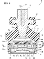
Fig. 1 is a vertical sectional view of an anti-vibration device according to a first embodiment. -
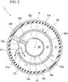
Fig. 2 is a cross-sectional view taken along line A-A of the anti-vibration device ofFig. 1 . -
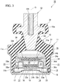
Fig. 3 is a vertical cross-sectional view of an anti-vibration device according to a second embodiment. - Hereinafter, a configuration of an anti-vibration device according to the first embodiment will be described with reference to
Figs. 1 to 3 . - As shown in
Fig. 1 , ananti-vibration device 1 includes a cylindrical first attachingmember 11 connected to one of a vibration generation unit and a vibration reception unit, a second attachingmember 12 attached to the other thereof, anelastic body 13 which connects the first attachingmember 11 and the second attachingmember 12, and apartition member 17 which is configured to partition aliquid chamber 14 in the first attachingmember 11 having liquid sealed therein into amain liquid chamber 15 having theelastic body 13 as a part of a partition wall, and an auxiliaryliquid chamber 16 in an axial direction along a central axis O of the first attachingmember 11. - In a case in which the
anti-vibration device 1 is used for, for example, an engine mounting for an automobile, the first attachingmember 11 is connected to a vehicle body as a vibration reception unit, and the second attachingmember 12 is connected to an engine as a vibration generation unit. As a result, transmission of vibration of the engine to the vehicle body is prevented. - Here, in this embodiment, the
main liquid chamber 15 side in the axial direction with respect to thepartition member 17 is referred to as an upper side, and theauxiliary liquid chamber 16 side is referred to as a lower side. Also, in a plan view of theanti-vibration device 1 as viewed from the axial direction, a direction orthogonal to the central axis O is referred to as a radial direction, and a direction of revolution around the central axis O is referred to as a circumferential direction. - The first attaching
member 11 includes anupper cylinder portion 11a located on the upper side, alower cylinder portion 11b having an inner diameter and an outer diameter smaller than theupper cylinder portion 11a and located on the lower side, and athrottle portion 11c which connects theupper cylinder portion 11a and thelower cylinder portion 11b and continuously extends over the entire circumference. An inner circumferential surface of thelower cylinder portion 11b is covered with coating rubber. The coating rubber is integrally formed with theelastic body 13. - The second attaching
member 12 is formed in a rod shape and is disposed coaxially with the central axis O. The second attachingmember 12 is disposed on the side inward from the first attachingmember 11 in the radial direction. Aflange portion 12a protruding outward in the radial direction is formed in an axial center portion of the second attachingmember 12. Afemale screw portion 12b extending downward in the axial direction is formed on an upper end surface of the second attachingmember 12. In a portion of the second attachingmember 12 located below theflange portion 12a, a taperedportion 12c which gradually decreases in diameter toward the lower side is formed. Theflange portion 12a is located above the first attachingmember 11. The lower end portion of the second attachingmember 12 is located below an upper end opening edge of the first attachingmember 11. - The
elastic body 13 connects theupper cylinder portion 11a of the first attachingmember 11 and the taperedportion 12c of the second attachingmember 12. The outer circumferential side of theelastic body 13 is integrally bonded by vulcanization to the respective inner circumferential surfaces of theupper cylinder portion 11a and thethrottle portion 11c of the first attachingmember 11. The inner circumferential side of theelastic body 13 is bonded by vulcanization to the outer circumferential surface of the taperedportion 12c of the second attachingmember 12. Theelastic body 13 gradually extends upward from the outer side in the radial direction to the inner side. An upper end opening portion of the first attachingmember 11 is hermetically sealed by theelastic body 13. - The
elastic body 13 is integrally formed with astopper rubber 32 which integrally covers the upper surface, the lower surface, and the outer circumferential surface of theflange portion 12a of the second attachingmember 12. - A
cylindrical diaphragm ring 18 is liquid-tightly fitted into the lower end portion of the first attachingmember 11 via the coating rubber. An outer circumferential portion of adiaphragm 19 formed to be elastically deformable using a rubber material or the like is bonded by vulcanization to the inner circumferential surface of thediaphragm ring 18. Thediaphragm ring 18 is fixed to the first attachingmember 11 by crimping the lower end portion of the first attachingmember 11 inward in the radial direction. Thediaphragm 19 seals the lower end opening portion of the first attachingmember 11. - A
liquid chamber 14 in which the liquid is sealed is defined in the first attachingmember 11 by thediaphragm 19 and theelastic body 13. As the liquid sealed in theliquid chamber 14, for example, water, ethylene glycol, or the like can be used. - The
partition member 17 is formed in a flat disc shape. Thepartition member 17 is fitted into the first attachingmember 11 and is sandwiched between the throttle portion 11e of the first attachingmember 11 and thediaphragm ring 18 in the axial direction. As a result, theliquid chamber 14 in the first attachingmember 11 is partitioned into the mainliquid chamber 15 defined by theelastic body 13 and thepartition member 17, and the auxiliaryliquid chamber 16 defined by thediaphragm 19 and thepartition member 17. Thediaphragm 19 is deformed to expand and contract with inflow and outflow of the liquid into and out of the auxiliaryliquid chamber 16. - The
partition member 17 includes amembrane 31 forming a part of the partition wall of the mainliquid chamber 15, anupper member 34 surrounding themembrane 31, alower member 33 fitted in theupper member 34, anannular fixing member 38 which fixes themembrane 31 to theupper member 34, and anintermediate chamber 35 having themembrane 31 as a part of the partition wall. - The
membrane 31 is formed in a disc shape by an elastic member such as rubber. Theintermediate chamber 35 is located on the side opposite to the mainliquid chamber 15 across themembrane 31. No penetrating hole is formed in themembrane 31 of the present embodiment. - The
upper member 34 has a fixedcylinder portion 34a surrounding themembrane 31, anannular fixing flange 34b protruding inward in the radial direction from the lower end opening edge of the fixedcylinder portion 34a, an annularupper flange 34c protruding outward in the radial direction from the lower end opening edge of the fixedcylinder portion 34a, anouter cylinder portion 34d extending downward from thefixed cylinder portion 34a, and alower flange 34e protruding outward in the radial direction from the lower end opening edge of theouter cylinder portion 34d. - The
upper flange 34c and thelower flange 34e are fitted in thelower cylinder portion 11b via coating rubber. - The
fixing member 38 is placed on the upper surface of the fixedcylinder portion 34a of theupper member 34, and is fixed to theupper member 34 by a bolt (not shown) or the like. As a result, the outer circumferential edge portion of themembrane 31 is fixed by being interposed in the axial direction between the fixingmember 38 and theupper member 34. Therefore, with the inflow and outflow of the liquid into the mainliquid chamber 15, themembrane 31 can elastically deform with the outer circumferential edge portion as the fixed end. - The
lower member 33 is fitted into theouter cylinder portion 34d of theupper member 34. Thelower member 33 includes an annularbottom plate portion 33a, aninner cylinder portion 33b extending upward from the inner circumferential edge of thebottom plate portion 33a, afirst blocking portion 33c for closing the lower end portion of theinner cylinder portion 33b, and anupper plate portion 33d extending outward in the radial direction from the upper end opening edge of theinner cylinder portion 33b. - The outer circumferential edge of the
bottom plate portion 33a is fitted in thelower cylinder portion 11b via the coating rubber. Thebottom plate portion 33a is in contact with or in proximity to thelower flange 34e of theupper member 34. Theinner cylinder portion 33b is disposed on the inner side of theouter cylinder portion 34d in the radial direction. Thefirst blocking portion 33c is located above thebottom plate portion 33a. - Here, the
partition member 17 of the present embodiment is provided with afirst orifice 21 through which the mainliquid chamber 15 and the auxiliaryliquid chamber 16 communicate with each other, asecond orifice 22 through which theintermediate chamber 35 and the auxiliaryliquid chamber 16 communicate with each other, and acommon opening 16a which forms an opening of each of thefirst orifice 21 and thesecond orifice 22 on the auxiliaryliquid chamber 16 side. - The flow resistances of the
first orifice 21 and thesecond orifice 22 are different from each other. Thesecond orifice 22 has a shorter flow path length and a greater cross-sectional area of the flow path than thefirst orifice 21, and has a smaller flow resistance than that of thefirst orifice 21. The flow path length and the flow path cross-sectional area of thefirst orifice 21 and thesecond orifice 22 are tuned so that the resonance frequency of each orifice becomes a predetermined frequency. - The resonance frequencies of the
first orifice 21 and thesecond orifice 22 may be equal to each other. - The
first orifice 21 is defined by theupper flange 34c, theouter cylinder portion 34d and thelower flange 34e of theupper member 34, and the coating rubber on the inner circumferential surface of thelower cylinder portion 11b. As shown inFig. 2 , thefirst orifice 21 and thesecond orifice 22 each extend in the circumferential direction. One end portion of thefirst orifice 21 communicates with thecommon opening 16a through afirst opening 21a formed in theouter cylinder portion 34d. The other end portion of thefirst orifice 21 communicates with the mainliquid chamber 15 through an opening (not shown) on the main liquid chamber side formed in theupper flange 34c. - The
first orifice 21 is formed in a C-shape in a cross-sectional view orthogonal to the axial direction, and a part thereof in the circumferential direction is blocked by anouter partition wall 34f protruding outward in the radial direction from theouter cylinder portion 34d. - The
second orifice 22 is disposed on the side inward from thefirst orifice 21 in the radial direction. As shown inFig. 1 , thesecond orifice 22 is defined by abottom plate portion 33a, aninner cylinder portion 33b and anupper plate portion 33d of thelower member 33, and anouter cylinder portion 34d of theupper member 34. As shown inFig. 2 , one end portion of thesecond orifice 22 communicates with theintermediate chamber 35 through asecond opening 35a formed in theinner cylinder portion 33b. The other end portion of thesecond orifice 22 communicates with the auxiliaryliquid chamber 16 through thecommon opening 16a. - The
second orifice 22 is formed in a C-shape in the cross-sectional view, and a part thereof in the circumferential direction is blocked by theinner partition wall 33f protruding outward in the radial direction from theinner cylinder portion 33b. Theinner partition wall 33f and theouter partition wall 34f are formed at the same position in the circumferential direction. The radially outer end surface of theinner partition wall 33f and the radially inner end surface of theouter partition wall 34f are in contact with or in proximity to each other in the radial direction. - As shown in
Fig. 1 , theintermediate chamber 35 is defined by theinner cylinder portion 33b and thefirst blocking portion 33c of thelower member 33, and themembrane 31. With the inflow and outflow of the liquid through thesecond orifice 22 and thesecond opening 35a with respect to theintermediate chamber 35, themembrane 31 deforms in the axial direction with the outer circumferential edge as the fixed end. - The
common opening 16a is formed on the wall surface of thebottom plate portion 33a that defines the inner surface of thesecond orifice 22, in thepartition member 17. As shown inFig. 2 , thecommon opening 16a is disposed at a position adjacent to theinner partition wall 33f and thefirst opening 21a. - Next, the operation of the
anti-vibration device 1 configured as described above will be described. - When vibration in the axial direction is input to the
anti-vibration device 1 and the first attachingmember 11 and the second attachingmember 12 are relatively displaced in the axial direction, theelastic body 13 which connects the first attachingmember 11 and the second attachingmember 12 to each other is elastically deformed. Next, the internal volume of the mainliquid chamber 15 changes, liquid flows back and forth through thefirst orifice 21 and thesecond orifice 22, liquid column resonance occurs in each orifice, and the vibration is attenuated and absorbed. - For example, when idle vibration having a relatively small amplitude in the axial direction and a relatively high frequency is input to the
anti-vibration device 1, themembrane 31 elastically deforms, and the liquid flows back and forth between the auxiliaryliquid chamber 16 and theintermediate chamber 35 through thesecond orifice 22. At this time, liquid column resonance occurs in thesecond orifice 22, and the vibration is attenuated and absorbed. Further, when shear vibration having a relatively large amplitude in the axial direction and a relatively small frequency is input to theanti-vibration device 1, theelastic body 13 is elastically deformed, and the liquid flows back and forth between the mainliquid chamber 15 and the auxiliaryliquid chamber 16 through thefirst orifice 21. At this time, liquid column resonance occurs in thefirst orifice 21, and the vibration is attenuated and absorbed. - Here, when vibration having an amplitude larger than shake vibration is input to the
anti-vibration device 1, after the first attachingmember 11 is greatly displaced downward with respect to the second attachingmember 12, when the restoring displacement is made to the upper side due to elasticity or the like of theelastic body 13, a large negative pressure is generated in the mainliquid chamber 15. Due to the negative pressure, the liquid in the auxiliaryliquid chamber 16 flows rapidly into thepartition member 17 from thecommon opening 16a. At this time, as shown inFig. 2 , the flow of the liquid having passed through thecommon opening 16a diverges into a flow F1 flowing in thefirst orifice 21 through thefirst opening 21a, and a flow F2 flowing in thesecond orifice 22. Further, theintermediate chamber 35 communicating with the auxiliaryliquid chamber 16 via thesecond orifice 22 is separated from the mainliquid chamber 15 by themembrane 31. - Thus, according to the
anti-vibration device 1 of the present embodiment, as compared with a case in which thefirst orifice 21 and thesecond orifice 22 communicate with the auxiliaryliquid chamber 16 through different openings, the flow velocity and the flow rate of the liquid flowing into the mainliquid chamber 15 through thefirst orifice 21 are suppressed, and occurrence of cavitation can be suppressed. - Furthermore, since the
common opening 16a is formed on the wall surface of thesecond orifice 22 disposed on the inner side than thefirst orifice 21 in the radial direction, the flow of the liquid flowing from the auxiliaryliquid chamber 16 into thepartition member 17 through thecommon opening 16a can be made to more reliably diverge into the flow F1 flowing in thefirst orifice 21 and the flow F2 flowing in thesecond orifice 22. Therefore, it is possible to more reliably reduce the flow velocity and the flow rate of the liquid flowing into the mainliquid chamber 15, and to suppress the occurrence of cavitation. - Next, a second embodiment of the present invention will be described with reference to
Fig. 3 , but the basic configuration is the same as that of the first embodiment. For this reason, components which are the same are denoted by the same reference numerals, the explanation thereof will be omitted, and only differences will be described. - The
anti-vibration device 10 of the present embodiment differs from theanti-vibration device 10 of the first embodiment in that amovable member 36 is accommodated in anaccommodating chamber 37 provided in thepartition member 17 to be deformable or displaceable in the axial direction. - As shown in
Fig. 3 , in thelower member 33 of thepartition member 17 of the present embodiment, asecond blocking portion 33e which blocks the axial center portion of theinner cylinder portion 33b is formed on the side above thefirst blocking portion 33c at an interval therefrom. The aforementionedaccommodating chamber 37 is defined by thefirst blocking portion 33c, thesecond blocking portion 33e, and theinner cylinder portion 33b. Further, theintermediate chamber 35 of the present embodiment is defined by thesecond blocking portion 33e, theinner cylinder portion 33b, and themembrane 31. Theaccommodating chamber 37 is disposed below theintermediate chamber 35 with thesecond blocking portion 33e interposed therebetween. - Further, in the
upper member 34 of the present embodiment, the fixedcylinder portion 34a extends toward the side outward from theouter cylinder portion 34d in the radial direction, and the portion in the lower surface of the fixedcylinder portion 34a on the outer side than theouter cylinder portion 34d in the radial direction defines thefirst orifice 21. - The fixing
member 38 and thelower member 33 are fixed to theupper member 34 with a bolt. - Further, in the
first blocking portion 33c of this embodiment, a plurality offirst communication holes 37b penetrating thefirst blocking portion 33c in the axial direction are formed at intervals in the radial direction and the circumferential direction. The plurality of first communication holes 37b allow theaccommodating chamber 37 and the auxiliaryliquid chamber 16 to communicate with each other. In thesecond blocking portion 33e, a plurality ofsecond communication holes 37a penetrating thesecond blocking portion 33e in the axial direction are formed at intervals in the radial direction and the circumferential direction. The plurality ofsecond communication holes 37a allow theaccommodating chamber 37 and theintermediate chamber 35 to communicate with each other. The plurality of first communication holes 37b and the plurality ofsecond communication holes 37a are formed on the wall surface defining theaccommodating chamber 37. - The plurality of
second communication holes 37a and the plurality offirst communication holes 37b are formed at equivalent positions in the radial direction and the circumferential direction. The flow resistance of each of the plurality ofsecond communication holes 37a and the plurality offirst communication holes 37b is smaller than the flow resistance of thefirst orifice 21 and thesecond orifice 22. - The
movable member 36 is formed in a disc shape of an elastic member such as rubber. The outer diameter of themovable member 36 is smaller than the inner diameter of theinner cylinder portion 33b, and the thickness of themovable member 36 is smaller than an axial distance between thefirst blocking portion 33c and thesecond blocking portion 33e. Therefore, a gap in the radial direction and the axial direction is formed between themovable member 36 and the inner surface of theaccommodating chamber 37. - According to the
anti-vibration device 10 of the present embodiment, since thefirst communication hole 37b and thesecond communication hole 37a are formed on the wall surface of theaccommodating chamber 37, when vibration is input to theanti-vibration device 10, the fluid flows into and out of theaccommodating chamber 37 through thecommunication holes - Here, since the
movable member 36 deformable or displaceable in the axial direction is accommodated in theaccommodating chamber 37, in the case in which the amplitude of vibration is relatively large and the frequency is relatively small, because a momentum of the flow of the liquid flowing into theaccommodating chamber 37 is strong, themovable member 36 is strongly pressed against the wall surface of theaccommodating chamber 37. As a result, since thefirst communication hole 37b or thesecond communication hole 37a is blocked, it is possible to restrict flow of the liquid between theintermediate chamber 35 and the auxiliaryliquid chamber 16 through theaccommodating chamber 37 and to increase the dynamic spring constant of the entireanti-vibration device 10. Therefore, it is possible to effectively attenuate vibrations of large amplitude. - On the other hand, when an idle vibration or the like having a relatively small vibration amplitude and a relatively large frequency is input to the
anti-vibration device 10, because the momentum of the flow of the liquid flowing into and out of theaccommodating chamber 37 is relatively weak, thefirst communication hole 37b and thesecond communication hole 37a are not blocked by themovable member 36 and are released. Thus, it is possible to allow the liquid to flow between theintermediate chamber 35 and the auxiliaryliquid chamber 16 through theaccommodating chamber 37 and to reduce the dynamic spring constant of the entireanti-vibration device 10 such that it becomes small. This makes it possible to effectively attenuate vibration of a small amplitude. - As described above, according to the
anti-vibration device 10 of the present embodiment, it is possible to effectively attenuate both vibration having large amplitude and vibration having small amplitude. - It should be noted that the technical scope of the present invention is not limited to the above-described embodiments, and various modifications can be made without departing from the spirit of the present invention.
- For example, in the
partition member 17 in the first embodiment, fine holes which penetrate thefirst blocking portion 33c shown inFig. 1 in the axial direction and allow theintermediate chamber 35 and the auxiliaryliquid chamber 16 to communicate with each other may be formed. In this case, when the amplitude of the vibration which is input to theanti-vibration device 1 is relatively large and the frequency is relatively small, since it is made difficult for the liquid to flow through the fine holes, it is possible to suppress flow of the liquid between theintermediate chamber 35 and the auxiliaryliquid chamber 16 and to increase the dynamic spring constant of the entireanti-vibration device 1. On the other hand, when the amplitude of the vibration which is input to theanti-vibration device 1 is relatively small and the frequency is relatively large, the liquid relatively easily flows through the fine holes, flowing of the liquid between theintermediate chamber 35 and the auxiliaryliquid chamber 16 is not suppressed, and the dynamic spring constant of the entireanti-vibration device 1 can be suppressed to be small. Thus, with a simple configuration, as in theanti-vibration device 10 of the second embodiment, it is possible to effectively attenuate both vibration with large amplitude and vibration with small amplitude. - In addition, the outer circumferential edge of the
movable member 36 in the second embodiment may be fixed to theaccommodating chamber 37. In this case, since themovable member 36 is deformed in the axial direction with the outer circumferential edge as the fixed end, it is possible to stabilize the state of deformation of themovable member 36 due to the vibration which is input to theanti-vibration device 10. Further, themovable member 36 may be have a penetration hole penetrating themovable member 36 in the axial direction formed therein. - Further, in the first embodiment and the second embodiment, the
common opening 16a may be formed on a wall surface which defines the inner surface of thefirst orifice 21. - In addition, in the first embodiment and the second embodiment, the
partition member 17 is formed with twoorifices partition member 17 having three or more orifices formed thereon may be formed. In this case, thepartition member 17 may have acommon opening 16a on the side of the auxiliaryliquid chamber 16 of two orifices among three or more orifices, or may have acommon opening 16a on the side of the auxiliaryliquid chamber 16 of three or more orifices. - According to the anti-vibration device of the present invention, since each of the first orifice and the second orifice communicates with the auxiliary liquid chamber through the common opening, when vibration having a relatively large amplitude and a relatively small frequency is input to the anti-vibration device and the main liquid chamber reaches a negative pressure, the flow of the liquid in the auxiliary liquid chamber having passed through the common opening diverges into the first orifice and the second orifice. Further, the intermediate chamber communicating with the auxiliary liquid chamber via the second orifice is separated from the main liquid chamber by the membrane.
- As a result, for example, since the flow velocity and the flow rate of the liquid flowing into the main liquid chamber through the first orifice are suppressed as compared with the case in which the first orifice and the second orifice communicate with the auxiliary liquid chamber through openings different from each other, occurrence of cavitation can be suppressed.
- Here, each of the first orifice and the second orifice extends in the circumferential direction, the second orifice is disposed on the inner side than the first orifice in the radial direction, and the common opening may be formed on a wall surface that defines an inner surface of the second orifice, in the partition member.
- In this case, since the common opening is formed on the wall surface of the second orifice disposed on the inner side than the first orifice in the radial direction, the flow of the liquid flowing out from the auxiliary liquid chamber through the common opening can be made to more reliably diverge into a flow flowing in the first orifice and a flow flowing in the second orifice. Therefore, the flow velocity and the flow rate of the liquid flowing into the main liquid chamber can be more reliably reduced, and the occurrence of cavitation can be suppressed.
- Further, the partition member is provided with an accommodating chamber that accommodates a movable member that is accommodated to be deformable or displaceable in the axial direction of the first attaching member, and on a wall surface that defines the accommodating chamber, a first communication hole through which the accommodating chamber and the auxiliary liquid chamber communicate with each other, and a second communication hole through which the accommodating chamber and the intermediate chamber communicate with each other may be formed.
- In this case, since the first communication hole through which the accommodating chamber and the auxiliary liquid chamber communicate with each other, and the second communication hole through which the accommodating chamber and the intermediate chamber communicate with each other are formed on the wall surface of the accommodating chamber provided in the partition member, when vibration is input to the anti-vibration device, liquid flows into and out of the accommodating chamber through each communication hole.
- Here, since the movable member that is deformable or displaceable in the axial direction is accommodated in the accommodating chamber, when the amplitude of the vibration which is input to the anti-vibration device is relatively large and the frequency is relatively small, because the momentum of the flow of the liquid flowing into the accommodating chamber is strong, the movable member is strongly pressed against the wall surface of the accommodating chamber, and because the first communication hole or the second communication hole is blocked, it is possible to restrict the flowing of the liquid between the intermediate chamber and the auxiliary liquid chamber through the accommodating chamber to increase the dynamic spring constant of the entire anti-vibration device. This makes it possible to effectively attenuate vibrations with large amplitude.
- On the other hand, when the amplitude of the vibration which is input to the anti-vibration device is relatively small and the frequency is relatively large, since the momentum of the flow of the liquid flowing in and out of the accommodating chamber becomes relatively weak, the first communication hole and the second communication hole are not blocked by the movable member, and the liquid flows to allow the liquid to flow between the intermediate chamber and the auxiliary liquid chamber through the accommodating chamber, thereby suppressing the dynamic spring constant of the entire ant-vibration device to be small. This makes it possible to effectively attenuate vibrations with small amplitude.
- As described above, according to the anti-vibration device having such a configuration, it is possible to effectively attenuate both vibration having large amplitude and vibration having small amplitude.
- Further, in the partition member, fine holes for allowing the intermediate chamber and the auxiliary liquid chamber to communicate with each other may be formed.
- In this case, when the amplitude of the vibration which is input to the anti-vibration device is relatively large and the frequency is relatively small, because the liquid is hard to flow through the fine holes formed in the partition member, it is possible to suppress flow of the liquid between the intermediate chamber and the auxiliary liquid chamber to increase the dynamic spring constant of the entire anti-vibration device.
- On the other hand, when the amplitude of the vibration which is input to the anti-vibration device is relatively small and the frequency is relatively large, because the liquid flows relatively easily through the fine holes, flow of the liquid between the intermediate chamber and the auxiliary liquid chamber is not suppressed, and it is possible to suppress the dynamic spring constant of the entire anti-vibration device to be small.
- As described above, according to the anti-vibration device of the present invention, it is possible to effectively attenuate both vibration with large amplitude and vibration with small amplitude with a simple configuration.
- Furthermore, it is possible to appropriately replace the constituent elements in the above-described embodiment with well-known constituent elements within the scope that does not depart from the gist of the present invention, and the above-described embodiment and modifications may be appropriately combined.
- According to the present invention, occurrence of cavitation can be suppressed in an anti-vibration device having two orifices.
-
- 1, 10 Anti-vibration device
- 11 First attaching member
- 12 Second attaching member
- 13 Elastic body
- 14 Liquid chamber
- 15 Main liquid chamber
- 16 Auxiliary liquid chamber
- 16a Common opening
- 17 Partition member
- 19 Diaphragm
- 21 First orifice
- 22 Second orifice
- 31 Membrane
- 35 Intermediate chamber
- 36 Movable member
- 37 Accommodating chamber
- 37a Second communication hole
- 37b First communication hole
Claims (6)
- An anti-vibration device comprising:a cylindrical first attaching member connected to one of a vibration generation unit and a vibration reception unit, and a second attaching member connected to the other thereof;an elastic body which connects the first attaching member and the second attaching member; anda partition member which is configured to partition a liquid chamber in the first attaching member into a main liquid chamber having the elastic body as a part of a partition wall of the main liquid chamber and an auxiliary liquid chamber,wherein the partition member includesa membrane which forms a part of the partition wall of the main liquid chamber, andan intermediate chamber which is located on a side opposite to the main liquid chamber with the membrane interposed therebetween, and has the membrane as a part of the partition wall of the main liquid chamber, andin the partition member,a first orifice through which the main liquid chamber and the auxiliary liquid chamber communicate with each other,a second orifice through which the intermediate chamber and the auxiliary liquid chamber communicate with each other, anda common opening which forms an opening on the auxiliary liquid chamber side of each of the first orifice and the second orifice are formed.
- The anti-vibration device according to claim 1, wherein each of the first orifice and the second orifice extends in a circumferential direction, and the second orifice is disposed on an inner side than the first orifice in a radial direction, and
the common opening is formed on a wall surface defining an inner surface of the second orifice in the partition member. - The anti-vibration device according to claim 1, wherein the partition member is provided with an accommodating chamber which accommodates a movable member accommodated to be deformable or displaceable in an axial direction of the first attaching member, and
a first communication hole through which the accommodating chamber and the auxiliary liquid chamber communicate with each other, and a second communication hole through which the accommodating chamber and the intermediate chamber communicate with each other are formed on the wall surface defining the accommodating chamber. - The anti-vibration device according to claim 2, wherein the partition member is provided with an accommodating chamber which accommodates a movable member accommodated to be deformable or displaceable in the axial direction of the first attaching member, and
a first communication hole through which the accommodating chamber and the auxiliary liquid chamber communicate with each other, and a second communication hole through which the accommodating chamber and the intermediate chamber communicate with each other are formed on the wall surface defining the accommodating chamber. - The anti-vibration device according to claim 1, wherein fine holes through which the intermediate chamber and the auxiliary liquid chamber communicate with each other are formed in the partition member.
- The anti-vibration device according to claim 2, wherein a fine hole through which the intermediate chamber and the auxiliary liquid chamber communicate with each other is formed in the partition member.
Applications Claiming Priority (2)
| Application Number | Priority Date | Filing Date | Title |
|---|---|---|---|
| JP2016181613A JP6817004B2 (en) | 2016-09-16 | 2016-09-16 | Anti-vibration device |
| PCT/JP2017/025566 WO2018051627A1 (en) | 2016-09-16 | 2017-07-13 | Anti-vibration device |
Publications (3)
| Publication Number | Publication Date |
|---|---|
| EP3514403A1 true EP3514403A1 (en) | 2019-07-24 |
| EP3514403A4 EP3514403A4 (en) | 2019-08-28 |
| EP3514403B1 EP3514403B1 (en) | 2025-03-19 |
Family
ID=61620000
Family Applications (1)
| Application Number | Title | Priority Date | Filing Date |
|---|---|---|---|
| EP17850533.5A Active EP3514403B1 (en) | 2016-09-16 | 2017-07-13 | Anti-vibration device |
Country Status (5)
| Country | Link |
|---|---|
| US (1) | US10989269B2 (en) |
| EP (1) | EP3514403B1 (en) |
| JP (1) | JP6817004B2 (en) |
| CN (1) | CN109690127A (en) |
| WO (1) | WO2018051627A1 (en) |
Families Citing this family (10)
| Publication number | Priority date | Publication date | Assignee | Title |
|---|---|---|---|---|
| CN113727874B (en) * | 2019-04-17 | 2024-08-02 | 株式会社普洛斯派 | Vibration isolation device |
| FR3096427B1 (en) * | 2019-05-24 | 2021-09-17 | Hutchinson | Hydraulic anti-vibration support |
| JP7346189B2 (en) | 2019-09-17 | 2023-09-19 | 株式会社プロスパイラ | Vibration isolator |
| JP7350629B2 (en) | 2019-11-07 | 2023-09-26 | 株式会社プロスパイラ | Vibration isolator |
| CN114728573B (en) | 2019-11-07 | 2025-11-04 | 株式会社普洛斯派 | Vibration isolation device |
| JP7290549B2 (en) * | 2019-11-07 | 2023-06-13 | 株式会社プロスパイラ | Anti-vibration device |
| CN114630975B (en) | 2019-11-07 | 2024-12-20 | 株式会社普洛斯派 | Vibration isolation device |
| WO2021090886A1 (en) | 2019-11-07 | 2021-05-14 | 株式会社ブリヂストン | Vibration-damping device |
| JP7399587B2 (en) | 2020-10-08 | 2023-12-18 | 株式会社プロスパイラ | Vibration isolator |
| JP2023134024A (en) * | 2022-03-14 | 2023-09-27 | 株式会社Subaru | Liquid filled mounting device |
Family Cites Families (18)
| Publication number | Priority date | Publication date | Assignee | Title |
|---|---|---|---|---|
| FR2592114B1 (en) * | 1985-12-24 | 1989-12-29 | Hutchinson Sa | IMPROVEMENTS ON HYDRAULIC ANTIVIBRATORY SUPPORTS |
| JP3198603B2 (en) * | 1992-03-23 | 2001-08-13 | 東海ゴム工業株式会社 | Fluid-filled mounting device |
| JP2827841B2 (en) * | 1993-10-15 | 1998-11-25 | 東海ゴム工業株式会社 | Fluid-filled anti-vibration assembly |
| JP3461913B2 (en) | 1994-06-20 | 2003-10-27 | 株式会社ブリヂストン | Anti-vibration device |
| JP3539067B2 (en) * | 1996-05-23 | 2004-06-14 | 東海ゴム工業株式会社 | Fluid-filled mounting device |
| JPH10132017A (en) * | 1996-10-28 | 1998-05-22 | Bridgestone Corp | Anti-vibration device |
| US6257562B1 (en) | 1998-12-11 | 2001-07-10 | Toyo Tire & Rubber Co., Ltd. | Liquid filled vibration isolating device |
| JP2006071109A (en) * | 1998-12-11 | 2006-03-16 | Toyo Tire & Rubber Co Ltd | Liquid-filled vibration isolator |
| JP4138165B2 (en) * | 1999-07-09 | 2008-08-20 | 東洋ゴム工業株式会社 | Liquid-filled vibration isolator |
| JP4688067B2 (en) * | 2005-07-14 | 2011-05-25 | 東海ゴム工業株式会社 | Fluid filled engine mount |
| JP4181162B2 (en) * | 2005-10-27 | 2008-11-12 | 東洋ゴム工業株式会社 | Liquid-filled vibration isolator |
| EP1995491A3 (en) * | 2007-05-22 | 2014-02-19 | Kurashiki Kako Co., Ltd. | Liquid-filled anti-vibration mounting device |
| CN101883932B (en) * | 2007-12-03 | 2013-09-11 | 株式会社普利司通 | Vibration damping device |
| JP5061132B2 (en) * | 2009-01-30 | 2012-10-31 | 東海ゴム工業株式会社 | Fluid filled vibration isolator |
| CN101813154B (en) * | 2009-02-24 | 2013-02-13 | 仓敷化工株式会社 | Liquid-filled vibration isolator |
| JP5094767B2 (en) * | 2009-02-27 | 2012-12-12 | 倉敷化工株式会社 | Liquid filled vibration isolator |
| JP5909077B2 (en) | 2011-11-08 | 2016-04-26 | 東洋ゴム工業株式会社 | Anti-vibration unit |
| CN102588502B (en) | 2011-12-30 | 2013-12-04 | 宁波泛亚汽车部件有限公司 | Hydraulic suspension of engine |
-
2016
- 2016-09-16 JP JP2016181613A patent/JP6817004B2/en active Active
-
2017
- 2017-07-13 WO PCT/JP2017/025566 patent/WO2018051627A1/en not_active Ceased
- 2017-07-13 CN CN201780055475.2A patent/CN109690127A/en active Pending
- 2017-07-13 EP EP17850533.5A patent/EP3514403B1/en active Active
- 2017-07-13 US US16/332,057 patent/US10989269B2/en active Active
Also Published As
| Publication number | Publication date |
|---|---|
| JP2018044650A (en) | 2018-03-22 |
| WO2018051627A1 (en) | 2018-03-22 |
| EP3514403A4 (en) | 2019-08-28 |
| CN109690127A (en) | 2019-04-26 |
| US20190226549A1 (en) | 2019-07-25 |
| EP3514403B1 (en) | 2025-03-19 |
| US10989269B2 (en) | 2021-04-27 |
| JP6817004B2 (en) | 2021-01-20 |
Similar Documents
| Publication | Publication Date | Title |
|---|---|---|
| EP3514403B1 (en) | Anti-vibration device | |
| US20200049224A1 (en) | Vibration-damping device | |
| US9400030B2 (en) | Vibration-damping device | |
| US20190168594A1 (en) | Hydraulic mount with negative-pressure valve | |
| US11441634B2 (en) | Anti-vibration device | |
| CN112074672B (en) | Vibration isolation device | |
| CN114630974A (en) | Vibration isolation device | |
| US11448284B2 (en) | Vibration isolation device | |
| EP4227552A1 (en) | Vibration isolation device | |
| US12203522B2 (en) | Vibration-damping device | |
| US11231083B2 (en) | Anti-vibration device | |
| JPWO2018198442A1 (en) | Anti-vibration device | |
| CN110506168B (en) | Vibration isolation device | |
| JP2015059580A (en) | Liquid-sealed type vibration control device | |
| JP5893482B2 (en) | Liquid-filled vibration isolator | |
| JP6654792B2 (en) | Anti-vibration device | |
| KR101823900B1 (en) | Structure of engine mount | |
| JP2016114146A (en) | Vibration control device | |
| JP2016114143A (en) | Vibration control device | |
| JP2012189192A (en) | Liquid sealing type vibration control device | |
| JP2016169786A (en) | Liquid sealed type vibration-proof device |
Legal Events
| Date | Code | Title | Description |
|---|---|---|---|
| STAA | Information on the status of an ep patent application or granted ep patent |
Free format text: STATUS: THE INTERNATIONAL PUBLICATION HAS BEEN MADE |
|
| PUAI | Public reference made under article 153(3) epc to a published international application that has entered the european phase |
Free format text: ORIGINAL CODE: 0009012 |
|
| STAA | Information on the status of an ep patent application or granted ep patent |
Free format text: STATUS: REQUEST FOR EXAMINATION WAS MADE |
|
| 17P | Request for examination filed |
Effective date: 20190308 |
|
| AK | Designated contracting states |
Kind code of ref document: A1 Designated state(s): AL AT BE BG CH CY CZ DE DK EE ES FI FR GB GR HR HU IE IS IT LI LT LU LV MC MK MT NL NO PL PT RO RS SE SI SK SM TR |
|
| AX | Request for extension of the european patent |
Extension state: BA ME |
|
| A4 | Supplementary search report drawn up and despatched |
Effective date: 20190730 |
|
| RIC1 | Information provided on ipc code assigned before grant |
Ipc: F16F 13/10 20060101AFI20190724BHEP |
|
| DAV | Request for validation of the european patent (deleted) | ||
| DAX | Request for extension of the european patent (deleted) | ||
| STAA | Information on the status of an ep patent application or granted ep patent |
Free format text: STATUS: EXAMINATION IS IN PROGRESS |
|
| 17Q | First examination report despatched |
Effective date: 20201207 |
|
| RAP1 | Party data changed (applicant data changed or rights of an application transferred) |
Owner name: PROSPIRA CORPORATION |
|
| GRAP | Despatch of communication of intention to grant a patent |
Free format text: ORIGINAL CODE: EPIDOSNIGR1 |
|
| STAA | Information on the status of an ep patent application or granted ep patent |
Free format text: STATUS: GRANT OF PATENT IS INTENDED |
|
| INTG | Intention to grant announced |
Effective date: 20241010 |
|
| P01 | Opt-out of the competence of the unified patent court (upc) registered |
Free format text: CASE NUMBER: APP_57716/2024 Effective date: 20241022 |
|
| GRAS | Grant fee paid |
Free format text: ORIGINAL CODE: EPIDOSNIGR3 |
|
| GRAA | (expected) grant |
Free format text: ORIGINAL CODE: 0009210 |
|
| STAA | Information on the status of an ep patent application or granted ep patent |
Free format text: STATUS: THE PATENT HAS BEEN GRANTED |
|
| AK | Designated contracting states |
Kind code of ref document: B1 Designated state(s): AL AT BE BG CH CY CZ DE DK EE ES FI FR GB GR HR HU IE IS IT LI LT LU LV MC MK MT NL NO PL PT RO RS SE SI SK SM TR |
|
| REG | Reference to a national code |
Ref country code: GB Ref legal event code: FG4D |
|
| REG | Reference to a national code |
Ref country code: CH Ref legal event code: EP |
|
| REG | Reference to a national code |
Ref country code: DE Ref legal event code: R096 Ref document number: 602017088445 Country of ref document: DE |
|
| REG | Reference to a national code |
Ref country code: IE Ref legal event code: FG4D |
|
| PG25 | Lapsed in a contracting state [announced via postgrant information from national office to epo] |
Ref country code: RS Free format text: LAPSE BECAUSE OF FAILURE TO SUBMIT A TRANSLATION OF THE DESCRIPTION OR TO PAY THE FEE WITHIN THE PRESCRIBED TIME-LIMIT Effective date: 20250619 |
|
| PG25 | Lapsed in a contracting state [announced via postgrant information from national office to epo] |
Ref country code: FI Free format text: LAPSE BECAUSE OF FAILURE TO SUBMIT A TRANSLATION OF THE DESCRIPTION OR TO PAY THE FEE WITHIN THE PRESCRIBED TIME-LIMIT Effective date: 20250319 |
|
| REG | Reference to a national code |
Ref country code: LT Ref legal event code: MG9D |
|
| PG25 | Lapsed in a contracting state [announced via postgrant information from national office to epo] |
Ref country code: NO Free format text: LAPSE BECAUSE OF FAILURE TO SUBMIT A TRANSLATION OF THE DESCRIPTION OR TO PAY THE FEE WITHIN THE PRESCRIBED TIME-LIMIT Effective date: 20250619 |
|
| PG25 | Lapsed in a contracting state [announced via postgrant information from national office to epo] |
Ref country code: HR Free format text: LAPSE BECAUSE OF FAILURE TO SUBMIT A TRANSLATION OF THE DESCRIPTION OR TO PAY THE FEE WITHIN THE PRESCRIBED TIME-LIMIT Effective date: 20250319 |
|
| PG25 | Lapsed in a contracting state [announced via postgrant information from national office to epo] |
Ref country code: LV Free format text: LAPSE BECAUSE OF FAILURE TO SUBMIT A TRANSLATION OF THE DESCRIPTION OR TO PAY THE FEE WITHIN THE PRESCRIBED TIME-LIMIT Effective date: 20250319 |
|
| PG25 | Lapsed in a contracting state [announced via postgrant information from national office to epo] |
Ref country code: GR Free format text: LAPSE BECAUSE OF FAILURE TO SUBMIT A TRANSLATION OF THE DESCRIPTION OR TO PAY THE FEE WITHIN THE PRESCRIBED TIME-LIMIT Effective date: 20250620 Ref country code: BG Free format text: LAPSE BECAUSE OF FAILURE TO SUBMIT A TRANSLATION OF THE DESCRIPTION OR TO PAY THE FEE WITHIN THE PRESCRIBED TIME-LIMIT Effective date: 20250319 |
|
| REG | Reference to a national code |
Ref country code: NL Ref legal event code: MP Effective date: 20250319 |
|
| REG | Reference to a national code |
Ref country code: AT Ref legal event code: MK05 Ref document number: 1777177 Country of ref document: AT Kind code of ref document: T Effective date: 20250319 |
|
| PG25 | Lapsed in a contracting state [announced via postgrant information from national office to epo] |
Ref country code: NL Free format text: LAPSE BECAUSE OF FAILURE TO SUBMIT A TRANSLATION OF THE DESCRIPTION OR TO PAY THE FEE WITHIN THE PRESCRIBED TIME-LIMIT Effective date: 20250319 |
|
| PG25 | Lapsed in a contracting state [announced via postgrant information from national office to epo] |
Ref country code: SE Free format text: LAPSE BECAUSE OF FAILURE TO SUBMIT A TRANSLATION OF THE DESCRIPTION OR TO PAY THE FEE WITHIN THE PRESCRIBED TIME-LIMIT Effective date: 20250319 |
|
| PG25 | Lapsed in a contracting state [announced via postgrant information from national office to epo] |
Ref country code: SM Free format text: LAPSE BECAUSE OF FAILURE TO SUBMIT A TRANSLATION OF THE DESCRIPTION OR TO PAY THE FEE WITHIN THE PRESCRIBED TIME-LIMIT Effective date: 20250319 |
|
| PG25 | Lapsed in a contracting state [announced via postgrant information from national office to epo] |
Ref country code: PT Free format text: LAPSE BECAUSE OF FAILURE TO SUBMIT A TRANSLATION OF THE DESCRIPTION OR TO PAY THE FEE WITHIN THE PRESCRIBED TIME-LIMIT Effective date: 20250721 Ref country code: ES Free format text: LAPSE BECAUSE OF FAILURE TO SUBMIT A TRANSLATION OF THE DESCRIPTION OR TO PAY THE FEE WITHIN THE PRESCRIBED TIME-LIMIT Effective date: 20250319 |
|
| PGFP | Annual fee paid to national office [announced via postgrant information from national office to epo] |
Ref country code: DE Payment date: 20250722 Year of fee payment: 9 |
|
| PG25 | Lapsed in a contracting state [announced via postgrant information from national office to epo] |
Ref country code: IT Free format text: LAPSE BECAUSE OF FAILURE TO SUBMIT A TRANSLATION OF THE DESCRIPTION OR TO PAY THE FEE WITHIN THE PRESCRIBED TIME-LIMIT Effective date: 20250319 Ref country code: PL Free format text: LAPSE BECAUSE OF FAILURE TO SUBMIT A TRANSLATION OF THE DESCRIPTION OR TO PAY THE FEE WITHIN THE PRESCRIBED TIME-LIMIT Effective date: 20250319 |
|
| PG25 | Lapsed in a contracting state [announced via postgrant information from national office to epo] |
Ref country code: AT Free format text: LAPSE BECAUSE OF FAILURE TO SUBMIT A TRANSLATION OF THE DESCRIPTION OR TO PAY THE FEE WITHIN THE PRESCRIBED TIME-LIMIT Effective date: 20250319 |
|
| PGFP | Annual fee paid to national office [announced via postgrant information from national office to epo] |
Ref country code: FR Payment date: 20250725 Year of fee payment: 9 |
|
| PG25 | Lapsed in a contracting state [announced via postgrant information from national office to epo] |
Ref country code: EE Free format text: LAPSE BECAUSE OF FAILURE TO SUBMIT A TRANSLATION OF THE DESCRIPTION OR TO PAY THE FEE WITHIN THE PRESCRIBED TIME-LIMIT Effective date: 20250319 Ref country code: CZ Free format text: LAPSE BECAUSE OF FAILURE TO SUBMIT A TRANSLATION OF THE DESCRIPTION OR TO PAY THE FEE WITHIN THE PRESCRIBED TIME-LIMIT Effective date: 20250319 |
|
| PG25 | Lapsed in a contracting state [announced via postgrant information from national office to epo] |
Ref country code: RO Free format text: LAPSE BECAUSE OF FAILURE TO SUBMIT A TRANSLATION OF THE DESCRIPTION OR TO PAY THE FEE WITHIN THE PRESCRIBED TIME-LIMIT Effective date: 20250319 |
|
| PG25 | Lapsed in a contracting state [announced via postgrant information from national office to epo] |
Ref country code: SK Free format text: LAPSE BECAUSE OF FAILURE TO SUBMIT A TRANSLATION OF THE DESCRIPTION OR TO PAY THE FEE WITHIN THE PRESCRIBED TIME-LIMIT Effective date: 20250319 |
|
| PG25 | Lapsed in a contracting state [announced via postgrant information from national office to epo] |
Ref country code: IS Free format text: LAPSE BECAUSE OF FAILURE TO SUBMIT A TRANSLATION OF THE DESCRIPTION OR TO PAY THE FEE WITHIN THE PRESCRIBED TIME-LIMIT Effective date: 20250719 |
|
| REG | Reference to a national code |
Ref country code: DE Ref legal event code: R097 Ref document number: 602017088445 Country of ref document: DE |
|
| PG25 | Lapsed in a contracting state [announced via postgrant information from national office to epo] |
Ref country code: DK Free format text: LAPSE BECAUSE OF FAILURE TO SUBMIT A TRANSLATION OF THE DESCRIPTION OR TO PAY THE FEE WITHIN THE PRESCRIBED TIME-LIMIT Effective date: 20250319 |
|
| PLBE | No opposition filed within time limit |
Free format text: ORIGINAL CODE: 0009261 |
|
| STAA | Information on the status of an ep patent application or granted ep patent |
Free format text: STATUS: NO OPPOSITION FILED WITHIN TIME LIMIT |
|
| REG | Reference to a national code |
Ref country code: CH Ref legal event code: L10 Free format text: ST27 STATUS EVENT CODE: U-0-0-L10-L00 (AS PROVIDED BY THE NATIONAL OFFICE) Effective date: 20260128 |
|
| REG | Reference to a national code |
Ref country code: CH Ref legal event code: H13 Free format text: ST27 STATUS EVENT CODE: U-0-0-H10-H13 (AS PROVIDED BY THE NATIONAL OFFICE) Effective date: 20260224 |
|
| 26N | No opposition filed |
Effective date: 20251222 |
|
| PG25 | Lapsed in a contracting state [announced via postgrant information from national office to epo] |
Ref country code: LU Free format text: LAPSE BECAUSE OF NON-PAYMENT OF DUE FEES Effective date: 20250713 |
|
| GBPC | Gb: european patent ceased through non-payment of renewal fee |
Effective date: 20250713 |
|
| REG | Reference to a national code |
Ref country code: BE Ref legal event code: MM Effective date: 20250731 |
|
| PG25 | Lapsed in a contracting state [announced via postgrant information from national office to epo] |
Ref country code: GB Free format text: LAPSE BECAUSE OF NON-PAYMENT OF DUE FEES Effective date: 20250713 |
|
| PG25 | Lapsed in a contracting state [announced via postgrant information from national office to epo] |
Ref country code: BE Free format text: LAPSE BECAUSE OF NON-PAYMENT OF DUE FEES Effective date: 20250731 |
|
| PG25 | Lapsed in a contracting state [announced via postgrant information from national office to epo] |
Ref country code: CH Free format text: LAPSE BECAUSE OF NON-PAYMENT OF DUE FEES Effective date: 20250731 |
|
| PG25 | Lapsed in a contracting state [announced via postgrant information from national office to epo] |
Ref country code: LT Free format text: LAPSE BECAUSE OF FAILURE TO SUBMIT A TRANSLATION OF THE DESCRIPTION OR TO PAY THE FEE WITHIN THE PRESCRIBED TIME-LIMIT Effective date: 20250319 |
|
| PG25 | Lapsed in a contracting state [announced via postgrant information from national office to epo] |
Ref country code: IE Free format text: LAPSE BECAUSE OF NON-PAYMENT OF DUE FEES Effective date: 20250713 |
|
| PG25 | Lapsed in a contracting state [announced via postgrant information from national office to epo] |
Ref country code: MC Free format text: LAPSE BECAUSE OF FAILURE TO SUBMIT A TRANSLATION OF THE DESCRIPTION OR TO PAY THE FEE WITHIN THE PRESCRIBED TIME-LIMIT Effective date: 20250319 |
|
| PG25 | Lapsed in a contracting state [announced via postgrant information from national office to epo] |
Ref country code: CY Free format text: LAPSE BECAUSE OF FAILURE TO SUBMIT A TRANSLATION OF THE DESCRIPTION OR TO PAY THE FEE WITHIN THE PRESCRIBED TIME-LIMIT Effective date: 20250319 |