EP3514366A1 - Intake device for multi-cylinder engine - Google Patents
Intake device for multi-cylinder engine Download PDFInfo
- Publication number
- EP3514366A1 EP3514366A1 EP17868341.3A EP17868341A EP3514366A1 EP 3514366 A1 EP3514366 A1 EP 3514366A1 EP 17868341 A EP17868341 A EP 17868341A EP 3514366 A1 EP3514366 A1 EP 3514366A1
- Authority
- EP
- European Patent Office
- Prior art keywords
- intake air
- intake
- intercooler
- cylinder engine
- cylindrical body
- Prior art date
- Legal status (The legal status is an assumption and is not a legal conclusion. Google has not performed a legal analysis and makes no representation as to the accuracy of the status listed.)
- Withdrawn
Links
Images


Classifications
-
- F—MECHANICAL ENGINEERING; LIGHTING; HEATING; WEAPONS; BLASTING
- F02—COMBUSTION ENGINES; HOT-GAS OR COMBUSTION-PRODUCT ENGINE PLANTS
- F02B—INTERNAL-COMBUSTION PISTON ENGINES; COMBUSTION ENGINES IN GENERAL
- F02B29/00—Engines characterised by provision for charging or scavenging not provided for in groups F02B25/00, F02B27/00 or F02B33/00 - F02B39/00; Details thereof
- F02B29/04—Cooling of air intake supply
- F02B29/045—Constructional details of the heat exchangers, e.g. pipes, plates, ribs, insulation, materials, or manufacturing and assembly
-
- F—MECHANICAL ENGINEERING; LIGHTING; HEATING; WEAPONS; BLASTING
- F02—COMBUSTION ENGINES; HOT-GAS OR COMBUSTION-PRODUCT ENGINE PLANTS
- F02B—INTERNAL-COMBUSTION PISTON ENGINES; COMBUSTION ENGINES IN GENERAL
- F02B29/00—Engines characterised by provision for charging or scavenging not provided for in groups F02B25/00, F02B27/00 or F02B33/00 - F02B39/00; Details thereof
- F02B29/04—Cooling of air intake supply
-
- F—MECHANICAL ENGINEERING; LIGHTING; HEATING; WEAPONS; BLASTING
- F02—COMBUSTION ENGINES; HOT-GAS OR COMBUSTION-PRODUCT ENGINE PLANTS
- F02M—SUPPLYING COMBUSTION ENGINES IN GENERAL WITH COMBUSTIBLE MIXTURES OR CONSTITUENTS THEREOF
- F02M26/00—Engine-pertinent apparatus for adding exhaust gases to combustion-air, main fuel or fuel-air mixture, e.g. by exhaust gas recirculation [EGR] systems
- F02M26/13—Arrangement or layout of EGR passages, e.g. in relation to specific engine parts or for incorporation of accessories
- F02M26/17—Arrangement or layout of EGR passages, e.g. in relation to specific engine parts or for incorporation of accessories in relation to the intake system
- F02M26/18—Thermal insulation or heat protection
-
- F—MECHANICAL ENGINEERING; LIGHTING; HEATING; WEAPONS; BLASTING
- F02—COMBUSTION ENGINES; HOT-GAS OR COMBUSTION-PRODUCT ENGINE PLANTS
- F02M—SUPPLYING COMBUSTION ENGINES IN GENERAL WITH COMBUSTIBLE MIXTURES OR CONSTITUENTS THEREOF
- F02M26/00—Engine-pertinent apparatus for adding exhaust gases to combustion-air, main fuel or fuel-air mixture, e.g. by exhaust gas recirculation [EGR] systems
- F02M26/13—Arrangement or layout of EGR passages, e.g. in relation to specific engine parts or for incorporation of accessories
- F02M26/17—Arrangement or layout of EGR passages, e.g. in relation to specific engine parts or for incorporation of accessories in relation to the intake system
- F02M26/19—Means for improving the mixing of air and recirculated exhaust gases, e.g. venturis or multiple openings to the intake system
-
- F—MECHANICAL ENGINEERING; LIGHTING; HEATING; WEAPONS; BLASTING
- F02—COMBUSTION ENGINES; HOT-GAS OR COMBUSTION-PRODUCT ENGINE PLANTS
- F02M—SUPPLYING COMBUSTION ENGINES IN GENERAL WITH COMBUSTIBLE MIXTURES OR CONSTITUENTS THEREOF
- F02M35/00—Combustion-air cleaners, air intakes, intake silencers, or induction systems specially adapted for, or arranged on, internal-combustion engines
- F02M35/10—Air intakes; Induction systems
- F02M35/10006—Air intakes; Induction systems characterised by the position of elements of the air intake system in direction of the air intake flow, i.e. between ambient air inlet and supply to the combustion chamber
- F02M35/10078—Connections of intake systems to the engine
- F02M35/10085—Connections of intake systems to the engine having a connecting piece, e.g. a flange, between the engine and the air intake being foreseen with a throttle valve, fuel injector, mixture ducts or the like
-
- F—MECHANICAL ENGINEERING; LIGHTING; HEATING; WEAPONS; BLASTING
- F02—COMBUSTION ENGINES; HOT-GAS OR COMBUSTION-PRODUCT ENGINE PLANTS
- F02M—SUPPLYING COMBUSTION ENGINES IN GENERAL WITH COMBUSTIBLE MIXTURES OR CONSTITUENTS THEREOF
- F02M35/00—Combustion-air cleaners, air intakes, intake silencers, or induction systems specially adapted for, or arranged on, internal-combustion engines
- F02M35/10—Air intakes; Induction systems
- F02M35/10242—Devices or means connected to or integrated into air intakes; Air intakes combined with other engine or vehicle parts
- F02M35/10268—Heating, cooling or thermal insulating means
-
- F—MECHANICAL ENGINEERING; LIGHTING; HEATING; WEAPONS; BLASTING
- F02—COMBUSTION ENGINES; HOT-GAS OR COMBUSTION-PRODUCT ENGINE PLANTS
- F02D—CONTROLLING COMBUSTION ENGINES
- F02D41/00—Electrical control of supply of combustible mixture or its constituents
- F02D41/0002—Controlling intake air
-
- F—MECHANICAL ENGINEERING; LIGHTING; HEATING; WEAPONS; BLASTING
- F02—COMBUSTION ENGINES; HOT-GAS OR COMBUSTION-PRODUCT ENGINE PLANTS
- F02M—SUPPLYING COMBUSTION ENGINES IN GENERAL WITH COMBUSTIBLE MIXTURES OR CONSTITUENTS THEREOF
- F02M35/00—Combustion-air cleaners, air intakes, intake silencers, or induction systems specially adapted for, or arranged on, internal-combustion engines
- F02M35/10—Air intakes; Induction systems
- F02M35/10091—Air intakes; Induction systems characterised by details of intake ducts: shapes; connections; arrangements
- F02M35/10144—Connections of intake ducts to each other or to another device
-
- F—MECHANICAL ENGINEERING; LIGHTING; HEATING; WEAPONS; BLASTING
- F02—COMBUSTION ENGINES; HOT-GAS OR COMBUSTION-PRODUCT ENGINE PLANTS
- F02M—SUPPLYING COMBUSTION ENGINES IN GENERAL WITH COMBUSTIBLE MIXTURES OR CONSTITUENTS THEREOF
- F02M35/00—Combustion-air cleaners, air intakes, intake silencers, or induction systems specially adapted for, or arranged on, internal-combustion engines
- F02M35/10—Air intakes; Induction systems
- F02M35/10209—Fluid connections to the air intake system; their arrangement of pipes, valves or the like
- F02M35/10222—Exhaust gas recirculation [EGR]; Positive crankcase ventilation [PCV]; Additional air admission, lubricant or fuel vapour admission
-
- F—MECHANICAL ENGINEERING; LIGHTING; HEATING; WEAPONS; BLASTING
- F02—COMBUSTION ENGINES; HOT-GAS OR COMBUSTION-PRODUCT ENGINE PLANTS
- F02M—SUPPLYING COMBUSTION ENGINES IN GENERAL WITH COMBUSTIBLE MIXTURES OR CONSTITUENTS THEREOF
- F02M35/00—Combustion-air cleaners, air intakes, intake silencers, or induction systems specially adapted for, or arranged on, internal-combustion engines
- F02M35/10—Air intakes; Induction systems
- F02M35/10314—Materials for intake systems
- F02M35/10321—Plastics; Composites; Rubbers
-
- F—MECHANICAL ENGINEERING; LIGHTING; HEATING; WEAPONS; BLASTING
- F02—COMBUSTION ENGINES; HOT-GAS OR COMBUSTION-PRODUCT ENGINE PLANTS
- F02M—SUPPLYING COMBUSTION ENGINES IN GENERAL WITH COMBUSTIBLE MIXTURES OR CONSTITUENTS THEREOF
- F02M35/00—Combustion-air cleaners, air intakes, intake silencers, or induction systems specially adapted for, or arranged on, internal-combustion engines
- F02M35/10—Air intakes; Induction systems
- F02M35/104—Intake manifolds
-
- Y—GENERAL TAGGING OF NEW TECHNOLOGICAL DEVELOPMENTS; GENERAL TAGGING OF CROSS-SECTIONAL TECHNOLOGIES SPANNING OVER SEVERAL SECTIONS OF THE IPC; TECHNICAL SUBJECTS COVERED BY FORMER USPC CROSS-REFERENCE ART COLLECTIONS [XRACs] AND DIGESTS
- Y02—TECHNOLOGIES OR APPLICATIONS FOR MITIGATION OR ADAPTATION AGAINST CLIMATE CHANGE
- Y02T—CLIMATE CHANGE MITIGATION TECHNOLOGIES RELATED TO TRANSPORTATION
- Y02T10/00—Road transport of goods or passengers
- Y02T10/10—Internal combustion engine [ICE] based vehicles
- Y02T10/12—Improving ICE efficiencies
Definitions
- the present disclosure relates to an intake device for a multi-cylinder engine.
- An intake manifold disclosed in Patent Literature 1 includes a main body, an upper cover, a lower cover, and a shell.
- the main body, the upper cover, and the lower cover are formed from resin materials.
- the shell is formed of a metal material.
- Patent Literature 1 discloses that the shell is joined to a bottom surface of the lower cover to serve as a reinforcing material which prevents deterioration of strength of the resin material under a high temperature.
- Patent Literature 1 Japanese Unexamined Patent Publication No. 2016-125369
- parts of the intake manifold excluding the shell are formed from resin materials to raise a concern that an attachment part to a cylinder head of an engine may lack in supporting rigidity.
- a branch part as the attachment part to the cylinder head of the engine is formed by welding the main body formed from a resin material and the upper cover similarly formed from a resin material, and the intercooler accommodated in the main body is a heavy load to be supported by the branch part formed from a resin material.
- Patent Literature 1 has a concern that the attachment part to the cylinder head of the engine lacks in supporting rigidity.
- An object of the present disclosure which intends to solve such a problem as described above, is to provide an intake device for a multi-cylinder engine which suppresses a weight increase while accommodating an intercooler, and which ensures high supporting rigidity of an attachment part to a cylinder head of the multi-cylinder engine.
- An intake device for a multi-cylinder engine includes: an intake manifold attached to a cylinder head of the multi-cylinder engine; an intercooler accommodated in the intake manifold to cool an intake air; and a heat insulation member interposed between the intake manifold and the cylinder head in the multi-cylinder engine.
- the intake manifold includes an intercooler housing that is a cylindrical body formed from a resin material and internally accommodates the intercooler, and an intake air distributor that is a cylindrical body formed of a metal material and has one opening connected to one opening of the intercooler housing, the intake air distributor distributing the intake air.
- the heat insulation member is interposed between another opening of the intake air distributor and the cylinder head in the multi-cylinder engine.
- the multi-cylinder engine 1 has a cylinder head 1a arranged on the upper side in a Z direction, and a cylinder block 1b attached under the cylinder head 1a.
- a plurality of cylinders are arranged in a direction vertical to the plane of the sheet of FIG. 1 .
- the direction vertical to the plane of the sheet of FIG. 1 is a direction of a cylinder row of the multi-cylinder engine 1.
- the intake device 2 is attached to the cylinder head 1a.
- the intake device 2 is equipped with an intake manifold 3, an intercooler 4, and a heat insulation member 5.
- the intake manifold 3 has a metal cylindrical body 31 that is a cylindrically-shaped body formed of a metal material, a resin cylindrical body 32 that is a cylindrically-shaped body formed from a resin material, and a back cover 33 attached on the right side of the resin cylindrical body 32 in an X direction.
- the metal cylindrical body 31 is provided as an intake air distributor which distributes an intake air to each intake air port 1c of the multi-cylinder engine 1.
- the intercooler 4 is accommodated in the resin cylindrical body 32 of the intake manifold 3. Specifically, the resin cylindrical body 32 is provided as an intercooler accommodating body.
- the intercooler 4 although detailed illustration thereof is omitted, has a plurality of cooling fins along a direction of a flow of an intake air.
- the heat insulation member 5 is interposed between the cylinder head 1a and the metal cylindrical body 31 of the intake manifold 3 in order to suppress heat transmission from the cylinder head 1a to the intake manifold 3. This makes an intake air path 3a in the intake manifold 3 and each intake air port 1c of the multi-cylinder engine 1 communicate with each other through an opening of the heat insulation member 5.
- the heat insulation member 5 is configured to have a thermal conductivity lower than that of at least the metal cylindrical body 31.
- a bottom surface of the metal cylindrical body 31 gradually inclines downward in a vertical direction (the Z direction) from a part of the resin cylindrical body 32 where the intercooler 4 is accommodated toward an end of the metal cylindrical body 31 on the cylinder head 1b side.
- FIG. 2 is a schematic plan view of the intake device 2 viewed from the upper side in the Z direction
- FIG. 3 is a schematic developed view showing developed components of the intake device 2.
- a throttle valve 6 is attached to a part of the resin cylindrical body 32 on a side opposite to a side of the connection with the metal cylindrical body 31.
- the throttle valve 6 is a valve for controlling a flow rate of an intake air to the intake manifold 3.
- the metal cylindrical body 31 of the intake manifold 3 is provided with an EGR (Exhaust Gas Recirculation) pipe 14. This causes a part of an exhaust gas to pass through the metal cylindrical body 31 of the intake manifold 3 to flow back to the multi-cylinder engine 1.
- EGR exhaust Gas Recirculation
- the metal cylindrical body 31 is integrally provided with an EGR distribution pipe 31a extending from a part of connection with the EGR pipe 14 toward both sides in an Y direction, and a plurality of EGR branch pipes 31b, 31c, 31d, 31e, 31f, and 31g branching from the EGR distribution pipe 31a to extend to the heat insulation member 5 side in the X direction.
- the EGR distribution pipe 31a is provided as an EGR distribution path.
- the EGR branch pipes 31b, 31c, 31d, 31e, 31f, and 31g enable the returned exhaust gas to be supplied to the metal cylindrical body 31 downstream of the resin cylindrical body 32 in the flow of the intake air, the resin cylindrical body 32 accommodating the intercooler 4.
- the metal cylindrical body 31 of the intake manifold 3 and the heat insulation member 5 are jointly fastened to the cylinder head 1a of the multi-cylinder engine 1 (see FIG. 1 ) by seven bolts 7 to 13 as first fastening members.
- the bolts 7 to 13 are inserted through the heat insulation member 5 in a thickness direction as indicated by arrows A 1 to A 7 and screw-fastened around the intake air ports 1c of the cylinder head 1a.
- the metal cylindrical body 31 and the resin cylindrical body 32 are fixed to each other by eight bolts 34 to 41 as second fastening members (in FIG. 2 and FIG. 3 , only the four bolts 34 to 37 are shown for the convenience of illustration).
- the resin cylindrical body 32 is provided with three openings 32a, 32b, and 32e in a frontward end in the Y direction. Of these openings, the throttle valve 6 is attached to a part in which the openings 32a and 32b are provided.
- the intercooler 4 is inserted from the opening 32e opened to be rectangular when viewed from the side in the Y direction.
- the intercooler 4 has a columnar external shape extending in the Y direction (a direction of the cylinder row). Then, the resin cylindrical body 32 and the intercooler 4 are fixed to each other by the bolts 51 to 54 as a result of contacting of the flange 4a of the intercooler 4 with side walls on the periphery of the opening 32e in the resin cylindrical body 32.
- the heat insulation member 5 is provided with a plurality of openings 5a to 51 arranged in the Y direction.
- a six-cylinder diesel engine is adopted as one example of a multi-cylinder engine 1.
- two each of opening 5a and 5b, 5c and 5d, 5e and 5f, 5g and 5h, 5i and 5j, and 5k and 51 are provided for the respective cylinders in the multi-cylinder engine 1.
- the openings 5a and 5b, 5c and 5d, 5e and 5f, 5g and 5h, 5i and 5j, and 5k and 51 function as connection paths which connect the metal cylinder 31 and the intake air ports 1c of the cylinder head 1a.
- the metal cylindrical body 31 has a width in the Y direction larger than a width in the Y direction of the resin cylindrical body 32 as shown in FIG. 2 and FIG. 3 .
- FIG. 4 is a schematic sectional view showing an air flow in the intake device 2.
- air introduced into the resin cylindrical body 32 from the openings 32a and 32b through the throttle valve 6 is divided into two of the intake air path 32d and the intake air path 32f divided by the dividing wall 32c.
- the air flowing through the intake air path 32d and the intake air path 32f passes through the intercooler 4 to be cooled.
- the intercooler 4 has the plurality of fins arranged along the X direction, although not illustrated, and the air passes between the plurality of fins. Then, at this time, heat is absorbed through the fins.
- the air having passed through the intercooler 4 flows from the intake air path 32g in the resin cylindrical body 32 into the metal cylindrical body 31.
- the metal cylindrical body 31 is provided therein with five partition walls 31h to 311 which extend in the X direction and are arranged to be spaced apart from each other.
- the metal cylindrical body 31 is internally zoned into the six intake air paths 31m to 31r.
- the six intake air paths 31m to 31r are not completely sectioned from each other but have some parts communicating with each other.
- the six intake air paths 31m to 31r correspond to the respective cylinders of the multi-cylinder engine 1 and also correspond to the paired openings 5a and 5b, 5c and 5d, 5e and 5f, 5g and 5h, 5i and 5j, and 5k and 51 in the heat insulation member 5.
- air having passed through the intake air paths 31m to 31r passes the openings 5a and 5b, 5c and 5d, 5e and 5f, 5g and 5h, 5i and 5j, and 5k and 51 as the connection paths to be supplied to the intake air port 1c of each cylinder in the multi-cylinder engine 1.
- FIG. 5 is a schematic front view of the metal cylindrical body 31 viewed from the side of a joint with the resin cylindrical body 32.
- the EGR branch pipes 31b to 31g are opened to be spaced apart from each other in the metal cylindrical body 31.
- the openings of the respective EGR branch pipes 31b to 31g are arranged at generally center parts of the intake air paths 31m to 31r in the Y direction, respectively.
- the openings of the respective EGR branch pipes 31b to 31g are arranged on the heat insulation member 5 side in a cylinder shaft direction (the direction vertical to the plane of the sheet) in the metal cylindrical body 31.
- FIG. 6 shows a section taken along VI-VI in FIG. 2
- FIG. 7 shows a section taken along VII-VII in FIG. 2
- FIG. 8 shows a section taken along VIII-VIII in FIG. 2
- FIG. 9 shows a section taken along IX-IX in FIG. 2 .
- the metal cylindrical body 31 has a height in the Z direction of an inner space thereof decreasing from the right side of the intake air path 31o in the X direction toward the left side.
- the inner space of the metal cylindrical body 31 has an opening cross section area gradually decreasing from a connection part with the resin cylindrical body 32 on the right side in the X direction toward a connection part with the heat insulation member 5 on the left side in the X direction.
- the EGR distribution pipe 31a is adjacent to the intake air path 31o with a thick part of the metal cylindrical body 31 provided therebetween. Since the part between the EGR distribution pipe 31a and the intake air path 31o is also formed of a metal material, heat of an exhaust gas flowing in the EGR distribution pipe 31a is cooled also by air flowing in the intake air path 31o.
- the configuration shown in FIG. 6 is the same as those of the intake air paths 31m, 31n, 31p, 31q, and 31r.
- the metal cylindrical body 31 and the resin cylindrical body 32 are fixed by fastening the bolts 35 and 39 at upper and lower sides in the Z direction.
- a length of the bolt 35 used for fastening the upper side in the Z direction is smaller than a height of the bolt 39 used for fastening the lower side.
- the height of the bolt 35 used for fastening the upper side can be set to be the same as that of the bolt 39 used for fastening the lower side.
- the resin cylindrical body 32 is set to have a larger insertion length than that of the metal cylindrical body 31. This is for suppressing stress on the bolts 35 and 39 to be small in the resin cylindrical body 32 where the intercooler 4 as a heavy load is accommodated.
- the EGR branch pipe 31c branching from the EGR distribution pipe 31a is formed not to extend along the Z direction but to extend obliquely in the Z direction so as to be angled toward the left side in the X direction. This enables the opening of the EGR branch pipe 31c to be located away from the intercooler 4. This makes it difficult to transmit heat of an exhaust gas to the intercooler 4 and to air passing through the intercooler 4.
- the expanded part is included in the opening of the metal cylindrical body 31 on the side of joint with the heat insulation member 5.
- a blade of a drill is allowed to enter through the opening on the left side of the metal cylindrical body 31 in the X direction. Accordingly, the configuration of the metal cylindrical body 31 according to the present embodiment facilitates manufacture to have an advantage in reducing manufacturing costs.
- the bolts 9 and 10 for attaching the intake manifold 3 to the cylinder head 1a of the multi-cylinder engine 1 are arranged on the inner space side of the metal cylindrical body 31.
- the bolts 9 and 10 are inserted through the metal cylindrical body 31 and the heat insulation member 5 to be screw-fastened around each intake air port 1c of the cylinder head 1a.
- the partition wall 31j provided in the metal cylindrical body 31 has a part of a lower part in the Z direction protruding to the right side in the X direction (a lower projection 31s).
- the lower projection 31s of the partition wall 31j in the metal cylinder 31 has a front end entering the resin cylindrical body 32. Then, the front end of the lower projection 31s is adjacent to a left end of the intercooler 4 in the X direction.
- the resin cylindrical body 32 is used as a part of the components forming the intake manifold 3, weight and manufacturing costs can be reduced more than in a case where the entire intake manifold is formed of a metal material.
- the metal cylindrical body 31 is used as a part of the components forming the intake manifold 3, and the metal cylindrical body 31 is disposed on the side of the attachment to the cylinder head 1a of the multi-cylinder engine 1. Therefore, even when a weight is increased due to accommodation of the intercooler 4, high supporting rigidity can be ensured for the cylinder head 1a.
- the heat insulation member 5 is interposed between the cylinder head 1a of the multi-cylinder engine 1 and the metal cylindrical body 31 of the intake manifold 3, it is possible to suppress transmission of heat from the cylinder head 1a to the intake manifold 3, thereby suppressing a temperature increase of an intake air.
- the intake device 2 enables a weight increase to be suppressed while accommodating the intercooler 4 in the intake manifold 3, and also enables high supporting rigidity to be ensured at the attachment part to the cylinder head 1a of the multi-cylinder engine 1.
- the intercooler 4 is configured to have a columnar external shape extending in the direction of the cylinder row (the Y direction) of the multi-cylinder engine 1, the intercooler 4 as a heavy load can be arranged at a part near the cylinder head 1a as a supporter, thereby suppressing a stress on the cylinder head 1a to be small.
- the present embodiment adopts such an arrangement mode of the intercooler 4 as described above, a large contact area in the connection part between the resin cylindrical body (intercooler housing) 32 and the metal cylindrical body (intake air distributor) 31 can be ensured to suppress local heat input.
- the metal cylindrical body 31 and the heat insulation member 5 are jointly fastened to the cylinder head 1a by the bolts 7 to 13 that are the first fastening members, high supporting rigidity with respect to the cylinder head 1a can be realized while reducing the number of the bolts 7 to 13.
- the metal cylindrical body 31 of the intake manifold 3 is provided with the EGR paths (the EGR distribution pipe 31a and the EGR branch pipes 31b to 31g) for returning the exhaust gas into the inner space of the metal cylindrical body 31, suppressing an excess increase of a combustion gas temperature enables generation of a nitrogen oxide (NOx) to be suppressed, as well as reducing a pumping loss during air intake.
- the EGR paths the EGR distribution pipe 31a and the EGR branch pipes 31b to 31g
- the resin cylindrical body 32 accommodating the intercooler 4, it is possible to prevent solid matters (soot etc.) contained in the exhaust gas from clogging the intercooler 4.
- the EGR distribution pipe 31a and the EGR branch pipes 31b to 31g are provided in the metal cylindrical body 31, the number of parts can be reduced and a layout of the intake device 2 and around the same can be simplified.
- forming the tube walls of the EGR distribution pipe 31a and the EGR branch pipes 31b to 31g with metal materials can accelerate reduction in an exhaust gas temperature. Accordingly, a volume of an exhaust gas can be reduced to suppress reduction in air filling efficiency and a loss of a NOx reduction effect caused by EGR.
- the resin cylindrical body 32 is provided with the dividing wall 32c to space the intake air path 32d and the intake air path 32f from each other, intake air distribution performance can be more excellent. Further, disposition of the dividing wall 32c in the resin cylindrical body 32 enables rigidity of the resin cylindrical body 32 to be improved.
- the back cover 33 is attached to the back side of the resin cylindrical body 32 (on the right side in the X direction in FIG. 3 ), rigidity of the resin cylindrical body 32 can be further increased. Further, attaching the back cover 33 as a separate body to the resin cylindrical body 32 enables the structure of the resin cylindrical body 32 to be simplified and enables reduction in manufacturing costs.
- the inner space of the metal cylindrical body 31 has the opening cross section area gradually decreasing from the upstream side of an air flow toward the downstream side (from the right side in the X direction toward the left side in FIG. 6 ), a flow speed of an intake air flowing into the intake air port 1c can be increased. It is accordingly possible to increase combustion efficiency.
- the metal cylindrical body 31 is configured to have a width larger than that of the resin cylindrical body 32, a further higher supporting rigidity can be ensured at the time of attachment to the cylinder head 1a.
- a length of insertion of each of the bolts 34 to 41 (the second fastening members) into the resin cylindrical body 32 at the time of attaching the metal cylindrical body 31 and the resin cylindrical body 32 is set to be larger than a length of insertion (a length of screwing) of the bolts 34 to 41 into the metal cylindrical body 31, even when the resin cylindrical body 32 has lower rigidity than that of the metal cylindrical body 31, high rigidity associated with attachment between the metal cylindrical body 31 and the resin cylindrical body 32 can be maintained.
- the cylinder bottom surface gradually inclines downward in the vertical direction (the Z direction) from the part of the resin cylindrical body 32 where the intercooler 4 is accommodated toward the end of the metal cylindrical body 31 on the cylinder head 1a side, even when drive of the multi-cylinder engine 1 is stopped and condensed water is generated in the intercooler 4, it is possible to suppress condensed water (water generated due to dew condensation) from remaining in the intake manifold 3.
- a six-cylinder diesel engine is adopted as one example of a multi-cylinder engine
- the present disclosure is not limited thereto.
- the number of cylinders only needs to be two or more and as a kind of engine, a gasoline engine can be adopted.
- the metal cylindrical body 31 and the resin cylindrical body 32 in the intake manifold 3 are both configured to have a cylindrical shape with a generally rectangular transverse section
- the present disclosure is not limited thereto.
- a metal cylindrical body or a resin cylindrical body having an oval transverse section as a whole can be adopted.
- the metal cylindrical body 31 can be configured, for example, to have the intake air paths 31m to 31r completed sectioned therebetween.
- the present disclosure is not limited thereto.
- it can be configured such that at least a part of a bottom plate of the metal cylindrical body overlaps a part of a bottom plate of the resin cylindrical body. This enables a fixing strength between the metal cylindrical body and the resin cylindrical body to be increased.
- the present disclosure is not limited thereto. For example, seven or less bolts may be used for fixing or nine or more bolts may be used for fixing.
- a rivet can be used other than a bolt.
- the metal cylindrical body and the resin cylindrical body can be integrated by insert-molding.
- the present disclosure is not limited thereto.
- six or less bolts may be used for the attachment or eight or more bolts may be used for the attachment.
- resin materials forming the resin cylindrical body 32 and the back cover 33 can include a nylon-based resin material with glass fiber mixed.
- An example of a metal material forming the metal cylindrical body 31 can include an aluminum alloy.
- the EGR paths are formed integrally with the metal cylindrical body 31, the present disclosure is not limited thereto. At least either one of the EGR distribution pipe 31a and the EGR branch pipes 31b to 31g can be a body separate from the metal cylindrical body.
- the dividing wall 32c is provided at the back side of the resin cylindrical body 32 to space the intake air path 32d and the intake air path 32f from each other, the present disclosure is not limited thereto.
- An intake device for a multi-cylinder engine includes: an intake manifold attached to a cylinder head of the multi-cylinder engine; an intercooler accommodated in the intake manifold to cool an intake air; and a heat insulation member interposed between the intake manifold and the cylinder head in the multi-cylinder engine.
- the intake manifold includes: an intercooler housing that is a cylindrical body formed from a resin material and internally accommodates the intercooler; and an intake air distributor that is a cylindrical body formed of a metal material and has one opening connected to one opening of the intercooler housing, the intake air distributor distributing the intake air.
- the heat insulation member is interposed between another opening of the intake air distributor and the cylinder head in the multi-cylinder engine.
- the intercooler housing of the intake manifold internally accommodates the intercooler, intake air can be cooled while reducing a size of the engine system and simplifying an intake system layout.
- the intercooler housing formed from a resin material is used as a part of the components forming the intake manifold, weight and manufacturing costs can be reduced.
- the intake air distributor formed of a metal material is used as a part of the components forming the intake manifold, and the metal cylindrical body is disposed on the side of the attachment to the cylinder head of the multi-cylinder engine. Therefore, even when a weight is increased due to accommodation of the intercooler in the intercooler housing, high supporting rigidity can be ensured for the cylinder head.
- the heat insulation member is interposed between the cylinder head of the multi-cylinder engine and the intake air distributor of the intake manifold, it is possible to suppress transmission of heat from the cylinder head to the intake manifold, thereby suppressing a temperature increase of an intake air.
- the intake device for a multi-cylinder engine enables a weight increase to be suppressed while accommodating the intercooler, and also enables high supporting rigidity to be ensured at the attachment part to the cylinder head of the multi-cylinder engine.
- An intake device for a multi-cylinder engine includes an intake manifold attached to a cylinder head of the multi-cylinder engine; an intercooler accommodated in the intake manifold to cool an intake air; and a heat insulation member interposed between the intake manifold and the cylinder head in the multi-cylinder engine.
- the intercooler is configured to have a columnar external shape extending in a direction of a cylinder row of the multi-cylinder engine.
- the intake manifold includes: an intercooler housing that is a cylindrical body formed from a resin material and internally accommodates the intercooler; and an intake air distributor that is a cylindrical body formed of a metal material and has one opening connected to one opening of the intercooler housing, the intake air distributor distributing the intake air.
- the heat insulation member is interposed between another opening of the intake air distributor and the cylinder head in the multi-cylinder engine, has a connection path which connects the intake air distributor and an intake air port of the cylinder head, and has a thermal conductivity lower than a thermal conductivity of the intake air distributor.
- the intercooler housing formed from a resin material is used as a part of the components forming the intake manifold, weight and manufacturing costs can be reduced.
- the intake air distributor formed of a metal material is used as a part of the components forming the intake manifold, and the metal cylindrical body is disposed on the side of the attachment to the cylinder head of the multi-cylinder engine. Therefore, even when a weight is increased due to accommodation of the intercooler in the intercooler housing, high supporting rigidity can be ensured for the cylinder head.
- the heat insulation member is interposed between the cylinder head of the multi-cylinder engine and the intake air distributor of the intake manifold, it is possible to suppress transmission of heat from the cylinder head to the intake manifold, thereby suppressing a temperature increase of an intake air.
- the intercooler since the intercooler is adopted which has a columnar external shape extending in the direction of the cylinder row of the multi-cylinder engine, the intercooler as a heavy load can be arranged at a part near the cylinder head as a supporter, thereby suppressing a stress on the cylinder head to be small. Additionally, according to the above aspect, since the present aspect enables a large contact area to be ensured in the connection part between the intercooler housing and the intake air distributor, local heat input can be suppressed.
- the intake air distributor and the heat insulation member are jointly fastened to the cylinder head of the multi-cylinder engine by first fastening members.
- the intake air distributor and the heat insulation member are jointly fastened to the cylinder head, high supporting rigidity with respect to the cylinder head can be realized while reducing the number of the first fastening members.
- the intake air distributor is provided with an EGR path for returning an exhaust gas into an inner space of the intake air distributor.
- the intake air distributor of the intake manifold is provided with the EGR (Exhaust Gas Recirculation) path, suppressing an excess increase of a combustion gas temperature enables generation of a nitrogen oxide (NOx) to be suppressed, as well as reducing a pumping loss during air intake.
- EGR exhaust Gas Recirculation
- the EGR path is provided in the intake air distributor downstream of the resin cylindrical body in the flow of the intake air, the resin cylindrical body accommodating the intercooler, it is possible to prevent solid matters (soot etc.) contained in the exhaust gas from the EGR path from clogging the intercooler.
- the EGR path in the intake air distributor includes an EGR distribution path which distributes the exhaust gas to a plurality of parts in a direction of a cylinder row of the multi-cylinder engine.
- the EGR path includes the EGR distribution path, the number of parts can be reduced and a layout of the intake device and around the same can be simplified.
- forming the EGR distribution path with a metal material can accelerate reduction in an exhaust gas temperature. Accordingly, a volume of an exhaust gas can be reduced to suppress reduction in air filling efficiency and a loss of a NOx reduction effect caused by EGR.
- the intercooler housing is provided with a plurality of intake air paths, and dividing walls for spacing the plurality of intake air paths are formed.
- the intercooler housing is provided with the dividing walls to space the plurality of intake air paths from each other, intake air distribution performance can be more excellent.
- disposition of the dividing wall in the intercooler housing enables rigidity of the intercooler housing to be improved.
- the intake manifold further has a back cover attached to the side of the other opening in the intercooler housing so as to cover a part of the other opening in the intercooler housing.
- attaching the back cover as a separate body to the intercooler housing enables the structure of the intercooler housing to be simplified and enables reduction in manufacturing costs.
- the inner space of the intake air distributor has an opening cross section area, in a vertical cross section, gradually decreasing from the one opening toward the other opening.
- the inner space since in the intake air distributor, the inner space has the opening cross section area gradually decreasing from the one opening toward the other opening, a flow speed of an intake air flowing into the intake air port can be increased. It is accordingly possible to increase combustion efficiency.
- a width of the intake air distributor is larger than a width of the intercooler housing.
- the intake air distributor is configured to have a width larger than that of the intercooler housing, a further higher supporting rigidity can be ensured at the time of attachment to the cylinder head.
- the intercooler housing and the intake air distributor are fastened by second fastening members having a shaft respectively, and in a longitudinal direction of the shaft of the second fastening member, a length of insertion of the shaft of the second fastening member into the intercooler housing is larger than a length of insertion of the shaft of the second fastening member into the intake air distributor.
- a length of insertion of the second fastening member into the intercooler housing is set to be larger than a length of insertion of the fastening member into the intake air distributor, even when the intercooler housing has lower rigidity than that of the intake air distributor, high rigidity associated with attachment between the intake air distributor and the intercooler housing can be maintained.
- a cylinder bottom surface gradually inclines downward in a vertical direction from a part of the intercooler housing where the intercooler is accommodated toward an end of the intake air distributor on a cylinder head side.
- the cylinder bottom surface gradually inclines downward in the vertical direction from the part of the resin cylindrical body where the intercooler is accommodated toward the end of the intake air distributor on the cylinder head side, even when drive of the multi-cylinder engine is stopped and condensed water is generated in the intercooler, it is possible to suppress condensed water (water generated due to dew condensation) from remaining in the intake manifold.
- the intake device for a multi-cylinder engine enables a weight increase to be suppressed while accommodating the intercooler, and also enables high supporting rigidity to be ensured at the attachment part to the cylinder head of the multi-cylinder engine.
Abstract
Description
- The present disclosure relates to an intake device for a multi-cylinder engine.
- Intake devices have been studied and developed in which an intercooler is accommodated in an intake manifold in order to reduce a size of an engine system and simplify an intake system layout (Patent Literature 1).
- An intake manifold disclosed in
Patent Literature 1 includes a main body, an upper cover, a lower cover, and a shell. In a configuration of the intake manifold, the main body, the upper cover, and the lower cover are formed from resin materials. The shell is formed of a metal material. - In the intake manifold disclosed in
Patent Literature 1, an intercooler is accommodated in the main body.Patent Literature 1 discloses that the shell is joined to a bottom surface of the lower cover to serve as a reinforcing material which prevents deterioration of strength of the resin material under a high temperature. - Patent Literature 1: Japanese Unexamined Patent Publication No.
2016-125369 - However, with the above technique disclosed in
Patent Literature 1, parts of the intake manifold excluding the shell are formed from resin materials to raise a concern that an attachment part to a cylinder head of an engine may lack in supporting rigidity. - Specifically, in the intake manifold disclosed in
Patent Literature 1, a branch part as the attachment part to the cylinder head of the engine is formed by welding the main body formed from a resin material and the upper cover similarly formed from a resin material, and the intercooler accommodated in the main body is a heavy load to be supported by the branch part formed from a resin material. - Thus, the intake manifold disclosed in
Patent Literature 1 has a concern that the attachment part to the cylinder head of the engine lacks in supporting rigidity. - An object of the present disclosure, which intends to solve such a problem as described above, is to provide an intake device for a multi-cylinder engine which suppresses a weight increase while accommodating an intercooler, and which ensures high supporting rigidity of an attachment part to a cylinder head of the multi-cylinder engine.
- An intake device for a multi-cylinder engine according to one aspect of the present disclosure includes: an intake manifold attached to a cylinder head of the multi-cylinder engine; an intercooler accommodated in the intake manifold to cool an intake air; and a heat insulation member interposed between the intake manifold and the cylinder head in the multi-cylinder engine.
- The intake manifold includes an intercooler housing that is a cylindrical body formed from a resin material and internally accommodates the intercooler, and an intake air distributor that is a cylindrical body formed of a metal material and has one opening connected to one opening of the intercooler housing, the intake air distributor distributing the intake air.
- The heat insulation member is interposed between another opening of the intake air distributor and the cylinder head in the multi-cylinder engine.
-
-
FIG. 1 is a schematic side view showing a multi-cylinder engine and an intake device according to an embodiment. -
FIG. 2 is a schematic plan view showing a configuration of the intake device. -
FIG. 3 is a schematic developed view showing the configuration of the intake device. -
FIG. 4 is a schematic sectional view showing an air flow in the intake device. -
FIG. 5 is a schematic front view showing a configuration of a metal cylindrical body in an intake manifold. -
FIG. 6 is a schematic sectional view, in a section taken along VI-VI inFIG. 2 , showing an internal configuration of the intake manifold. -
FIG. 7 is a schematic sectional view, in a section taken along VII-VII inFIG. 2 , showing the internal configuration of the intake manifold. -
FIG. 8 is a schematic sectional view, in a section taken along VIII-VIII inFIG. 2 , showing the internal configuration of the intake manifold. -
FIG. 9 is a schematic sectional view, in a section taken along IX-IX- inFIG. 2 , showing the internal configuration of the intake manifold. - In the following, an embodiment will be described with reference to the drawings. The embodiment to be described below is one aspect of the present disclosure, and the present disclosure is not limited to the embodiment set forth below except for a substantial configuration thereof.
- Schematic configurations and arrangement modes of a
multi-cylinder engine 1 and anintake device 2 according to the present embodiment will be described with reference toFIG. 1 . - As shown in
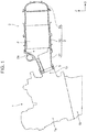
FIG. 1 , themulti-cylinder engine 1 has acylinder head 1a arranged on the upper side in a Z direction, and acylinder block 1b attached under thecylinder head 1a. In themulti-cylinder engine 1, a plurality of cylinders are arranged in a direction vertical to the plane of the sheet ofFIG. 1 . In other words, the direction vertical to the plane of the sheet ofFIG. 1 is a direction of a cylinder row of themulti-cylinder engine 1. - The
intake device 2 is attached to thecylinder head 1a. Theintake device 2 is equipped with anintake manifold 3, anintercooler 4, and aheat insulation member 5. - The
intake manifold 3 has a metalcylindrical body 31 that is a cylindrically-shaped body formed of a metal material, a resincylindrical body 32 that is a cylindrically-shaped body formed from a resin material, and aback cover 33 attached on the right side of the resincylindrical body 32 in an X direction. The metalcylindrical body 31 is provided as an intake air distributor which distributes an intake air to eachintake air port 1c of themulti-cylinder engine 1. - The
intercooler 4 is accommodated in the resincylindrical body 32 of theintake manifold 3. Specifically, the resincylindrical body 32 is provided as an intercooler accommodating body. Theintercooler 4, although detailed illustration thereof is omitted, has a plurality of cooling fins along a direction of a flow of an intake air. - The
heat insulation member 5 is interposed between thecylinder head 1a and the metalcylindrical body 31 of theintake manifold 3 in order to suppress heat transmission from thecylinder head 1a to theintake manifold 3. This makes anintake air path 3a in theintake manifold 3 and eachintake air port 1c of themulti-cylinder engine 1 communicate with each other through an opening of theheat insulation member 5. - The
heat insulation member 5 is configured to have a thermal conductivity lower than that of at least the metalcylindrical body 31. - While the
intake manifold 3 is attached to thecylinder head 1a of themulti-cylinder engine 1, a bottom surface of the metalcylindrical body 31 gradually inclines downward in a vertical direction (the Z direction) from a part of the resincylindrical body 32 where theintercooler 4 is accommodated toward an end of the metalcylindrical body 31 on thecylinder head 1b side. This, when themulti-cylinder engine 1 stops, causes condensed water (water generated due to dew condensation) generated on a top surface of theintercooler 4 not to remain in theintake manifold 3 but to be discharged to eachintake air port 1c of themulti-cylinder engine 1. - Detailed configuration of the
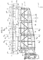
intake device 2 will be described with reference toFIG. 2 andFIG. 3 .FIG. 2 is a schematic plan view of theintake device 2 viewed from the upper side in the Z direction, andFIG. 3 is a schematic developed view showing developed components of theintake device 2. - As shown in
FIG. 2 andFIG. 3 , athrottle valve 6 is attached to a part of the resincylindrical body 32 on a side opposite to a side of the connection with the metalcylindrical body 31. Thethrottle valve 6 is a valve for controlling a flow rate of an intake air to theintake manifold 3. - Also as shown in
FIG. 2 , the metalcylindrical body 31 of theintake manifold 3 is provided with an EGR (Exhaust Gas Recirculation)pipe 14. This causes a part of an exhaust gas to pass through the metalcylindrical body 31 of theintake manifold 3 to flow back to themulti-cylinder engine 1. - The metal
cylindrical body 31 is integrally provided with anEGR distribution pipe 31a extending from a part of connection with theEGR pipe 14 toward both sides in an Y direction, and a plurality ofEGR branch pipes EGR distribution pipe 31a to extend to theheat insulation member 5 side in the X direction. In the metalcylindrical body 31 according to the present embodiment, theEGR distribution pipe 31a is provided as an EGR distribution path. - Here, the EGR
branch pipes cylindrical body 31 downstream of the resincylindrical body 32 in the flow of the intake air, the resincylindrical body 32 accommodating theintercooler 4. - The metal
cylindrical body 31 of theintake manifold 3 and theheat insulation member 5 are jointly fastened to thecylinder head 1a of the multi-cylinder engine 1 (seeFIG. 1 ) by sevenbolts 7 to 13 as first fastening members. Thebolts 7 to 13 are inserted through theheat insulation member 5 in a thickness direction as indicated by arrows A1 to A7 and screw-fastened around theintake air ports 1c of thecylinder head 1a. - In the
intake manifold 3, the metalcylindrical body 31 and the resincylindrical body 32 are fixed to each other by eightbolts 34 to 41 as second fastening members (inFIG. 2 andFIG. 3 , only the fourbolts 34 to 37 are shown for the convenience of illustration). - As shown in
FIG. 3 , in a right side end of the resincylindrical body 32 in the X direction, generally a half the length in the Y direction, is covered with a dividingwall 32c and generally a remaining half the length is opened as anintake air path 32d. Then, theback cover 33 is joined to the resincylindrical body 32 so as to cover the dividingwall 32c and theintake air path 32d of the resin cylindrical body from the right side in the X direction. - The resin
cylindrical body 32 is provided with threeopenings throttle valve 6 is attached to a part in which theopenings - On the other hand, from the
opening 32e opened to be rectangular when viewed from the side in the Y direction, theintercooler 4 is inserted. Theintercooler 4 has a columnar external shape extending in the Y direction (a direction of the cylinder row). Then, the resincylindrical body 32 and theintercooler 4 are fixed to each other by thebolts 51 to 54 as a result of contacting of theflange 4a of theintercooler 4 with side walls on the periphery of theopening 32e in the resincylindrical body 32. - As shown in
FIG. 3 , theheat insulation member 5 is provided with a plurality ofopenings 5a to 51 arranged in the Y direction. In the present embodiment, a six-cylinder diesel engine is adopted as one example of amulti-cylinder engine 1. Then, in theheat insulation member 5, two each ofopening multi-cylinder engine 1. - The
openings metal cylinder 31 and theintake air ports 1c of thecylinder head 1a. - Here, in the
intake manifold 3, the metalcylindrical body 31 has a width in the Y direction larger than a width in the Y direction of the resincylindrical body 32 as shown inFIG. 2 andFIG. 3 . - An air flow in the
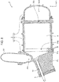
intake device 2 will be described with reference toFIG. 4. FIG. 4 is a schematic sectional view showing an air flow in theintake device 2. - As shown in
FIG. 4 , air introduced into the resincylindrical body 32 from theopenings throttle valve 6 is divided into two of theintake air path 32d and theintake air path 32f divided by the dividingwall 32c. - The air flowing through the
intake air path 32d and theintake air path 32f passes through theintercooler 4 to be cooled. Theintercooler 4 has the plurality of fins arranged along the X direction, although not illustrated, and the air passes between the plurality of fins. Then, at this time, heat is absorbed through the fins. - The air having passed through the
intercooler 4 flows from theintake air path 32g in the resincylindrical body 32 into the metalcylindrical body 31. - Here, the metal
cylindrical body 31 is provided therein with fivepartition walls 31h to 311 which extend in the X direction and are arranged to be spaced apart from each other. By the disposition of thepartition walls 31h to 311, the metalcylindrical body 31 is internally zoned into the sixintake air paths 31m to 31r. The sixintake air paths 31m to 31r, however, are not completely sectioned from each other but have some parts communicating with each other. - Additionally, the six
intake air paths 31m to 31r correspond to the respective cylinders of themulti-cylinder engine 1 and also correspond to the pairedopenings heat insulation member 5. - Accordingly, air having passed through the
intake air paths 31m to 31r passes theopenings intake air port 1c of each cylinder in themulti-cylinder engine 1. - Description will be made of openings of the
EGR branch pipes 31b to 31g formed in the metalcylindrical body 31 with reference toFIG. 5. FIG. 5 is a schematic front view of the metalcylindrical body 31 viewed from the side of a joint with the resincylindrical body 32. - As shown in
FIG. 5 , theEGR branch pipes 31b to 31g are opened to be spaced apart from each other in the metalcylindrical body 31. The openings of the respectiveEGR branch pipes 31b to 31g are arranged at generally center parts of theintake air paths 31m to 31r in the Y direction, respectively. - The openings of the respective
EGR branch pipes 31b to 31g are arranged on theheat insulation member 5 side in a cylinder shaft direction (the direction vertical to the plane of the sheet) in the metalcylindrical body 31. - An internal configuration of the
intake manifold 3 will be described with reference toFIG. 6 to FIG. 9 .FIG. 6 shows a section taken along VI-VI inFIG. 2 ,FIG. 7 shows a section taken along VII-VII inFIG. 2 ,FIG. 8 shows a section taken along VIII-VIII inFIG. 2 , andFIG. 9 shows a section taken along IX-IX inFIG. 2 . - First, as shown in
FIG. 6 , the metalcylindrical body 31 has a height in the Z direction of an inner space thereof decreasing from the right side of the intake air path 31o in the X direction toward the left side. In other words, the inner space of the metalcylindrical body 31 has an opening cross section area gradually decreasing from a connection part with the resincylindrical body 32 on the right side in the X direction toward a connection part with theheat insulation member 5 on the left side in the X direction. - Also as shown in
FIG. 6 , in the metalcylindrical body 31, theEGR distribution pipe 31a is adjacent to the intake air path 31o with a thick part of the metalcylindrical body 31 provided therebetween. Since the part between theEGR distribution pipe 31a and the intake air path 31o is also formed of a metal material, heat of an exhaust gas flowing in theEGR distribution pipe 31a is cooled also by air flowing in the intake air path 31o. - The configuration shown in
FIG. 6 is the same as those of theintake air paths - Additionally, as shown in
FIG. 6 , the metalcylindrical body 31 and the resincylindrical body 32 are fixed by fastening thebolts bolt 35 used for fastening the upper side in the Z direction is smaller than a height of thebolt 39 used for fastening the lower side. The height of thebolt 35 used for fastening the upper side can be set to be the same as that of thebolt 39 used for fastening the lower side. - As to a length of insertion of each of the
bolts cylindrical body 32 is set to have a larger insertion length than that of the metalcylindrical body 31. This is for suppressing stress on thebolts cylindrical body 32 where theintercooler 4 as a heavy load is accommodated. - This is also the case with insertion positions of
other bolts cylindrical body 31 and the resincylindrical body 32. - Next, as shown in
FIG. 7 , theEGR branch pipe 31c branching from theEGR distribution pipe 31a is formed not to extend along the Z direction but to extend obliquely in the Z direction so as to be angled toward the left side in the X direction. This enables the opening of theEGR branch pipe 31c to be located away from theintercooler 4. This makes it difficult to transmit heat of an exhaust gas to theintercooler 4 and to air passing through theintercooler 4. - Additionally, as shown in
FIG. 7 , obliquely extending theEGR branch pipe 31c to merge with theintake air path 31n makes it difficult to generate irregular air and exhaust gas flows (turbulence). - Also, as shown in
FIG. 7 , in a case where an extension direction of theEGR branch pipe 31c is expanded, the expanded part is included in the opening of the metalcylindrical body 31 on the side of joint with theheat insulation member 5. Specifically, at the time of processing theEGR branch pipe 31c, a blade of a drill is allowed to enter through the opening on the left side of the metalcylindrical body 31 in the X direction. Accordingly, the configuration of the metalcylindrical body 31 according to the present embodiment facilitates manufacture to have an advantage in reducing manufacturing costs. - The foregoing is also the case with other
EGR branch pipes cylindrical body 31. - Next, as shown in
FIG. 8 andFIG. 9 , thebolts intake manifold 3 to thecylinder head 1a of themulti-cylinder engine 1 are arranged on the inner space side of the metalcylindrical body 31. Thebolts cylindrical body 31 and theheat insulation member 5 to be screw-fastened around eachintake air port 1c of thecylinder head 1a. - This is also the case with
other bolts intake manifold 3 to thecylinder head 1a. - Next, like a part indicated by an arrow B in
FIG. 8 , thepartition wall 31j provided in the metalcylindrical body 31 has a part of a lower part in the Z direction protruding to the right side in the X direction (alower projection 31s). Thelower projection 31s of thepartition wall 31j in themetal cylinder 31 has a front end entering the resincylindrical body 32. Then, the front end of thelower projection 31s is adjacent to a left end of theintercooler 4 in the X direction. - This is also the case with the
partition walls cylindrical body 31. - In the present embodiment, since the
intercooler 4 is accommodated in the cylinder of the resincylindrical body 32 in theintake manifold 3, intake air can be cooled while reducing a size of the engine system and simplifying an intake system layout. - Additionally, in the present embodiment, since the resin
cylindrical body 32 is used as a part of the components forming theintake manifold 3, weight and manufacturing costs can be reduced more than in a case where the entire intake manifold is formed of a metal material. - Also in the present embodiment, the metal
cylindrical body 31 is used as a part of the components forming theintake manifold 3, and the metalcylindrical body 31 is disposed on the side of the attachment to thecylinder head 1a of themulti-cylinder engine 1. Therefore, even when a weight is increased due to accommodation of theintercooler 4, high supporting rigidity can be ensured for thecylinder head 1a. - Also in the present embodiment, the
heat insulation member 5 is interposed between thecylinder head 1a of themulti-cylinder engine 1 and the metalcylindrical body 31 of theintake manifold 3, it is possible to suppress transmission of heat from thecylinder head 1a to theintake manifold 3, thereby suppressing a temperature increase of an intake air. - Accordingly, the
intake device 2 according to the present embodiment enables a weight increase to be suppressed while accommodating theintercooler 4 in theintake manifold 3, and also enables high supporting rigidity to be ensured at the attachment part to thecylinder head 1a of themulti-cylinder engine 1. - Also in the present embodiment, since the
intercooler 4 is configured to have a columnar external shape extending in the direction of the cylinder row (the Y direction) of themulti-cylinder engine 1, theintercooler 4 as a heavy load can be arranged at a part near thecylinder head 1a as a supporter, thereby suppressing a stress on thecylinder head 1a to be small. - Additionally, since the present embodiment adopts such an arrangement mode of the
intercooler 4 as described above, a large contact area in the connection part between the resin cylindrical body (intercooler housing) 32 and the metal cylindrical body (intake air distributor) 31 can be ensured to suppress local heat input. - Also in the present embodiment, since the metal
cylindrical body 31 and theheat insulation member 5 are jointly fastened to thecylinder head 1a by thebolts 7 to 13 that are the first fastening members, high supporting rigidity with respect to thecylinder head 1a can be realized while reducing the number of thebolts 7 to 13. - Additionally, in the present embodiment, since the metal
cylindrical body 31 of theintake manifold 3 is provided with the EGR paths (theEGR distribution pipe 31a and theEGR branch pipes 31b to 31g) for returning the exhaust gas into the inner space of the metalcylindrical body 31, suppressing an excess increase of a combustion gas temperature enables generation of a nitrogen oxide (NOx) to be suppressed, as well as reducing a pumping loss during air intake. - Also in the present embodiment, since the openings of the
EGR branch pipes 31b to 31g are provided in the metalcylindrical body 31 downstream of the resincylindrical body 32 in the flow of air, the resincylindrical body 32 accommodating theintercooler 4, it is possible to prevent solid matters (soot etc.) contained in the exhaust gas from clogging theintercooler 4. - Also in the present embodiment, since the
EGR distribution pipe 31a and theEGR branch pipes 31b to 31g are provided in the metalcylindrical body 31, the number of parts can be reduced and a layout of theintake device 2 and around the same can be simplified. - Additionally, in the present embodiment, forming the tube walls of the
EGR distribution pipe 31a and theEGR branch pipes 31b to 31g with metal materials can accelerate reduction in an exhaust gas temperature. Accordingly, a volume of an exhaust gas can be reduced to suppress reduction in air filling efficiency and a loss of a NOx reduction effect caused by EGR. - Also, in the present embodiment, since the resin
cylindrical body 32 is provided with the dividingwall 32c to space theintake air path 32d and theintake air path 32f from each other, intake air distribution performance can be more excellent. Further, disposition of the dividingwall 32c in the resincylindrical body 32 enables rigidity of the resincylindrical body 32 to be improved. - Additionally, in the present embodiment, since the
back cover 33 is attached to the back side of the resin cylindrical body 32 (on the right side in the X direction inFIG. 3 ), rigidity of the resincylindrical body 32 can be further increased. Further, attaching theback cover 33 as a separate body to the resincylindrical body 32 enables the structure of the resincylindrical body 32 to be simplified and enables reduction in manufacturing costs. - Also, in the present embodiment, since in the metal
cylindrical body 31 of theintake manifold 3, the inner space of the metalcylindrical body 31 has the opening cross section area gradually decreasing from the upstream side of an air flow toward the downstream side (from the right side in the X direction toward the left side inFIG. 6 ), a flow speed of an intake air flowing into theintake air port 1c can be increased. It is accordingly possible to increase combustion efficiency. - Additionally, in the present embodiment, since the metal
cylindrical body 31 is configured to have a width larger than that of the resincylindrical body 32, a further higher supporting rigidity can be ensured at the time of attachment to thecylinder head 1a. - Also, in the present embodiment, since a length of insertion of each of the
bolts 34 to 41 (the second fastening members) into the resincylindrical body 32 at the time of attaching the metalcylindrical body 31 and the resincylindrical body 32 is set to be larger than a length of insertion (a length of screwing) of thebolts 34 to 41 into the metalcylindrical body 31, even when the resincylindrical body 32 has lower rigidity than that of the metalcylindrical body 31, high rigidity associated with attachment between the metalcylindrical body 31 and the resincylindrical body 32 can be maintained. - Additionally, in the present embodiment, since the cylinder bottom surface gradually inclines downward in the vertical direction (the Z direction) from the part of the resin
cylindrical body 32 where theintercooler 4 is accommodated toward the end of the metalcylindrical body 31 on thecylinder head 1a side, even when drive of themulti-cylinder engine 1 is stopped and condensed water is generated in theintercooler 4, it is possible to suppress condensed water (water generated due to dew condensation) from remaining in theintake manifold 3. - While in the above embodiment, a six-cylinder diesel engine is adopted as one example of a multi-cylinder engine, the present disclosure is not limited thereto. The number of cylinders only needs to be two or more and as a kind of engine, a gasoline engine can be adopted.
- While in the above embodiment, the metal
cylindrical body 31 and the resincylindrical body 32 in theintake manifold 3 are both configured to have a cylindrical shape with a generally rectangular transverse section, the present disclosure is not limited thereto. For example, a metal cylindrical body or a resin cylindrical body having an oval transverse section as a whole can be adopted. - While in the above embodiment, parts of the
intake air paths 31m to 31r are connected to each other in the metalcylindrical body 31, the present disclosure is not limited thereto. The metalcylindrical body 31 can be configured, for example, to have theintake air paths 31m to 31r completed sectioned therebetween. - Additionally, while the above embodiment adopts the configuration where the metal
cylindrical body 31 and the resincylindrical body 32 are fixed by the fastening members with the opening edges thereof abutted to each other, the present disclosure is not limited thereto. For example, it can be configured such that at least a part of a bottom plate of the metal cylindrical body overlaps a part of a bottom plate of the resin cylindrical body. This enables a fixing strength between the metal cylindrical body and the resin cylindrical body to be increased. - Also, while the above embodiment uses eight
bolts 34 to 41 as the second fastening members for fixing the metalcylindrical body 31 and the resincylindrical body 32, the present disclosure is not limited thereto. For example, seven or less bolts may be used for fixing or nine or more bolts may be used for fixing. - Additionally, as the second fastening member for use in joining the metal
cylindrical body 31 and the resincylindrical body 32, a rivet can be used other than a bolt. For joining the metalcylindrical body 31 and the resincylindrical body 32, the metal cylindrical body and the resin cylindrical body can be integrated by insert-molding. - Also, while the above embodiment uses seven
bolts 7 to 13 as the first fastening members for attaching the metalcylindrical body 31 to the cylinder head la, the present disclosure is not limited thereto. For example, six or less bolts may be used for the attachment or eight or more bolts may be used for the attachment. - Additionally, although the above embodiment does not in particular refer to a metal material forming the metal
cylindrical body 31 and resin materials forming the resincylindrical body 32 and theback cover 33, various materials can be used. An example of resin materials forming the resincylindrical body 32 and theback cover 33 can include a nylon-based resin material with glass fiber mixed. An example of a metal material forming the metalcylindrical body 31 can include an aluminum alloy. - Also, while in the above embodiment, the EGR paths (the
EGR distribution pipe 31a and theEGR branch pipes 31b to 31g) are formed integrally with the metalcylindrical body 31, the present disclosure is not limited thereto. At least either one of theEGR distribution pipe 31a and theEGR branch pipes 31b to 31g can be a body separate from the metal cylindrical body. - Also, while in the above embodiment, the dividing
wall 32c is provided at the back side of the resincylindrical body 32 to space theintake air path 32d and theintake air path 32f from each other, the present disclosure is not limited thereto. For example, it is possible to have no dividing wall or it is conversely possible to provide two or more dividing walls to space three or more intake air paths. - An intake device for a multi-cylinder engine according to one aspect of the present disclosure includes: an intake manifold attached to a cylinder head of the multi-cylinder engine; an intercooler accommodated in the intake manifold to cool an intake air; and a heat insulation member interposed between the intake manifold and the cylinder head in the multi-cylinder engine.
- The intake manifold includes: an intercooler housing that is a cylindrical body formed from a resin material and internally accommodates the intercooler; and an intake air distributor that is a cylindrical body formed of a metal material and has one opening connected to one opening of the intercooler housing, the intake air distributor distributing the intake air.
- The heat insulation member is interposed between another opening of the intake air distributor and the cylinder head in the multi-cylinder engine.
- According to the above aspect, since the intercooler housing of the intake manifold internally accommodates the intercooler, intake air can be cooled while reducing a size of the engine system and simplifying an intake system layout.
- Further, according to the above aspect, since the intercooler housing formed from a resin material is used as a part of the components forming the intake manifold, weight and manufacturing costs can be reduced.
- Furthermore, according to the above aspect, the intake air distributor formed of a metal material is used as a part of the components forming the intake manifold, and the metal cylindrical body is disposed on the side of the attachment to the cylinder head of the multi-cylinder engine. Therefore, even when a weight is increased due to accommodation of the intercooler in the intercooler housing, high supporting rigidity can be ensured for the cylinder head.
- Furthermore, according to the above aspect, since the heat insulation member is interposed between the cylinder head of the multi-cylinder engine and the intake air distributor of the intake manifold, it is possible to suppress transmission of heat from the cylinder head to the intake manifold, thereby suppressing a temperature increase of an intake air.
- Accordingly, the intake device for a multi-cylinder engine according to the above aspect enables a weight increase to be suppressed while accommodating the intercooler, and also enables high supporting rigidity to be ensured at the attachment part to the cylinder head of the multi-cylinder engine.
- An intake device for a multi-cylinder engine according to one aspect of the present disclosure includes an intake manifold attached to a cylinder head of the multi-cylinder engine; an intercooler accommodated in the intake manifold to cool an intake air; and a heat insulation member interposed between the intake manifold and the cylinder head in the multi-cylinder engine.
- The intercooler is configured to have a columnar external shape extending in a direction of a cylinder row of the multi-cylinder engine.
- The intake manifold includes: an intercooler housing that is a cylindrical body formed from a resin material and internally accommodates the intercooler; and an intake air distributor that is a cylindrical body formed of a metal material and has one opening connected to one opening of the intercooler housing, the intake air distributor distributing the intake air.
- The heat insulation member is interposed between another opening of the intake air distributor and the cylinder head in the multi-cylinder engine, has a connection path which connects the intake air distributor and an intake air port of the cylinder head, and has a thermal conductivity lower than a thermal conductivity of the intake air distributor.
- Also in the above aspect, since the intercooler is accommodated in the intercooler housing of the intake manifold, intake air can be cooled while reducing a size of the engine system and simplifying the intake system layout.
- Also in the above aspect, since the intercooler housing formed from a resin material is used as a part of the components forming the intake manifold, weight and manufacturing costs can be reduced.
- Also in the above aspect, the intake air distributor formed of a metal material is used as a part of the components forming the intake manifold, and the metal cylindrical body is disposed on the side of the attachment to the cylinder head of the multi-cylinder engine. Therefore, even when a weight is increased due to accommodation of the intercooler in the intercooler housing, high supporting rigidity can be ensured for the cylinder head.
- Also in the above aspect, since the heat insulation member is interposed between the cylinder head of the multi-cylinder engine and the intake air distributor of the intake manifold, it is possible to suppress transmission of heat from the cylinder head to the intake manifold, thereby suppressing a temperature increase of an intake air.
- Further, according to the above aspect, since the intercooler is adopted which has a columnar external shape extending in the direction of the cylinder row of the multi-cylinder engine, the intercooler as a heavy load can be arranged at a part near the cylinder head as a supporter, thereby suppressing a stress on the cylinder head to be small. Additionally, according to the above aspect, since the present aspect enables a large contact area to be ensured in the connection part between the intercooler housing and the intake air distributor, local heat input can be suppressed.
- In the intake device for a multi-cylinder engine according to another aspect of the present disclosure, in the above configuration, the intake air distributor and the heat insulation member are jointly fastened to the cylinder head of the multi-cylinder engine by first fastening members.
- According to the above aspect, since the intake air distributor and the heat insulation member are jointly fastened to the cylinder head, high supporting rigidity with respect to the cylinder head can be realized while reducing the number of the first fastening members.
- In the intake device for a multi-cylinder engine according to still another aspect of the present disclosure, in the above configuration, the intake air distributor is provided with an EGR path for returning an exhaust gas into an inner space of the intake air distributor.
- According to the above aspect, since the intake air distributor of the intake manifold is provided with the EGR (Exhaust Gas Recirculation) path, suppressing an excess increase of a combustion gas temperature enables generation of a nitrogen oxide (NOx) to be suppressed, as well as reducing a pumping loss during air intake.
- Also according to the above aspect, since the EGR path is provided in the intake air distributor downstream of the resin cylindrical body in the flow of the intake air, the resin cylindrical body accommodating the intercooler, it is possible to prevent solid matters (soot etc.) contained in the exhaust gas from the EGR path from clogging the intercooler.
- In the intake device for a multi-cylinder engine according to yet another aspect of the present disclosure, the EGR path in the intake air distributor includes an EGR distribution path which distributes the exhaust gas to a plurality of parts in a direction of a cylinder row of the multi-cylinder engine.
- According to the above aspect, since the EGR path includes the EGR distribution path, the number of parts can be reduced and a layout of the intake device and around the same can be simplified.
- Also according to the above aspect, forming the EGR distribution path with a metal material can accelerate reduction in an exhaust gas temperature. Accordingly, a volume of an exhaust gas can be reduced to suppress reduction in air filling efficiency and a loss of a NOx reduction effect caused by EGR.
- In the intake device for a multi-cylinder engine according to yet another aspect of the present disclosure, in the above configuration, the intercooler housing is provided with a plurality of intake air paths, and dividing walls for spacing the plurality of intake air paths are formed.
- According to the above aspect, since the intercooler housing is provided with the dividing walls to space the plurality of intake air paths from each other, intake air distribution performance can be more excellent.
- Further, according to the above aspect, disposition of the dividing wall in the intercooler housing enables rigidity of the intercooler housing to be improved.
- In the intake device for a multi-cylinder engine according to yet another aspect of the present disclosure, in the above configuration, the intake manifold further has a back cover attached to the side of the other opening in the intercooler housing so as to cover a part of the other opening in the intercooler housing.
- According to the above aspect, since the back cover is attached to the other opening side in the intercooler housing, rigidity of the intercooler housing can be further improved.
- Further, according to the above aspect, attaching the back cover as a separate body to the intercooler housing enables the structure of the intercooler housing to be simplified and enables reduction in manufacturing costs.
- In the intake device for a multi-cylinder engine according to yet another aspect of the present disclosure, in the above configuration, the inner space of the intake air distributor has an opening cross section area, in a vertical cross section, gradually decreasing from the one opening toward the other opening.
- According to the above aspect, since in the intake air distributor, the inner space has the opening cross section area gradually decreasing from the one opening toward the other opening, a flow speed of an intake air flowing into the intake air port can be increased. It is accordingly possible to increase combustion efficiency.
- In the intake device for a multi-cylinder engine according to yet another aspect of the present disclosure, when viewed from the direction of the cylinder row of the multi-cylinder engine, a width of the intake air distributor is larger than a width of the intercooler housing.
- According to the above aspect, since the intake air distributor is configured to have a width larger than that of the intercooler housing, a further higher supporting rigidity can be ensured at the time of attachment to the cylinder head.
- In the intake device for a multi-cylinder engine according to yet another aspect of the present disclosure, in the above configuration, the intercooler housing and the intake air distributor are fastened by second fastening members having a shaft respectively, and in a longitudinal direction of the shaft of the second fastening member, a length of insertion of the shaft of the second fastening member into the intercooler housing is larger than a length of insertion of the shaft of the second fastening member into the intake air distributor.
- According to the above aspect, since a length of insertion of the second fastening member into the intercooler housing is set to be larger than a length of insertion of the fastening member into the intake air distributor, even when the intercooler housing has lower rigidity than that of the intake air distributor, high rigidity associated with attachment between the intake air distributor and the intercooler housing can be maintained.
- In the intake device for a multi-cylinder engine according to yet another aspect of the present disclosure, in the above configuration, in the intake manifold, a cylinder bottom surface gradually inclines downward in a vertical direction from a part of the intercooler housing where the intercooler is accommodated toward an end of the intake air distributor on a cylinder head side.
- According to the above aspect, since the cylinder bottom surface gradually inclines downward in the vertical direction from the part of the resin cylindrical body where the intercooler is accommodated toward the end of the intake air distributor on the cylinder head side, even when drive of the multi-cylinder engine is stopped and condensed water is generated in the intercooler, it is possible to suppress condensed water (water generated due to dew condensation) from remaining in the intake manifold.
- As described in the foregoing, the intake device for a multi-cylinder engine according to each of the above aspects enables a weight increase to be suppressed while accommodating the intercooler, and also enables high supporting rigidity to be ensured at the attachment part to the cylinder head of the multi-cylinder engine.
Claims (11)
- An intake device for a multi-cylinder engine, the intake device comprising:an intake manifold attached to a cylinder head of the multi-cylinder engine;an intercooler accommodated in the intake manifold to cool an intake air; anda heat insulation member interposed between the intake manifold and the cylinder head in the multi-cylinder engine, whereinthe intake manifold includes:an intercooler housing that is a cylindrical body formed from a resin material and internally accommodates the intercooler; andan intake air distributor that is a cylindrical body formed of a metal material and has one opening connected to one opening of the intercooler housing, the intake air distributor distributing the intake air, andthe heat insulation member is interposed between another opening of the intake air distributor and the cylinder head in the multi-cylinder engine.
- An intake device for a multi-cylinder engine, the intake device comprising:an intake manifold attached to a cylinder head of the multi-cylinder engine;an intercooler accommodated in the intake manifold to cool an intake air; anda heat insulation member interposed between the intake manifold and the cylinder head in the multi-cylinder engine, whereinthe intercooler is configured to have a columnar external shape extending in a direction of a cylinder row of the multi-cylinder engine,the intake manifold has:an intercooler housing that is a cylindrical body formed from a resin material and internally accommodates the intercooler; andan intake air distributor that is a cylindrical body formed of a metal material and has one opening connected to one opening of the intercooler housing, the intake air distributor distributing the intake air, andthe heat insulation member is interposed between another opening of the intake air distributor and the cylinder head in the multi-cylinder engine, has a connection path which connects the intake air distributor and an intake air port of the cylinder head, and has a thermal conductivity lower than a thermal conductivity of the intake air distributor.
- The intake device for a multi-cylinder engine according to claim 1 or 2, wherein
the intake air distributor and the heat insulation member are jointly fastened to the cylinder head of the multi-cylinder engine by first fastening members. - The intake device for a multi-cylinder engine according to any one of claims 1 to 3, wherein
the intake air distributor is provided with an EGR path for returning an exhaust gas into an inner space of the intake air distributor. - The intake device for a multi-cylinder engine according to claim 4, wherein
the EGR path in the intake air distributor includes an EGR distribution path which distributes the exhaust gas to a plurality of parts in a direction of a cylinder row of the multi-cylinder engine. - The intake device for a multi-cylinder engine according to any one of claims 1 to 5, wherein the intercooler housing is provided with a plurality of intake air paths, and dividing walls for spacing the plurality of intake air paths are formed.
- The intake device for a multi-cylinder engine according to claim 6, wherein,
the intake manifold further has a back cover attached to the side of the other opening in the intercooler housing so as to cover a part of the other opening in the intercooler housing. - The intake device for a multi-cylinder engine according to any one of claims 1 to 7, wherein
the inner space of the intake air distributor has an opening cross section area, in a vertical cross section, gradually decreasing from the one opening toward the other opening. - The intake device for a multi-cylinder engine according to any one of claims 1 to 8, wherein
in the direction of the cylinder row of the multi-cylinder engine, a width of the intake air distributor is larger than a width of the intercooler housing. - The intake device for a multi-cylinder engine according to any one of claims 1 to 9, wherein
the intercooler housing and the intake air distributor are fastened by second fastening members having a shaft respectively, and
in a longitudinal direction of the shaft of the second fastening member, a length of insertion of the shaft of the second fastening member into the intercooler housing is larger than a length of insertion of the shaft of the second fastening member into the intake air distributor. - The intake device for a multi-cylinder engine according to any one of claims 1 to 10, wherein
in the intake manifold, a cylinder bottom surface gradually inclines downward in a vertical direction from a part of the intercooler housing where the intercooler is accommodated toward an end of the intake air distributor on a cylinder head side.
Applications Claiming Priority (2)
| Application Number | Priority Date | Filing Date | Title |
|---|---|---|---|
| JP2016216317A JP6394680B2 (en) | 2016-11-04 | 2016-11-04 | Intake device for multi-cylinder engine with intercooler |
| PCT/JP2017/038464 WO2018084042A1 (en) | 2016-11-04 | 2017-10-25 | Intake device for multi-cylinder engine |
Publications (2)
| Publication Number | Publication Date |
|---|---|
| EP3514366A1 true EP3514366A1 (en) | 2019-07-24 |
| EP3514366A4 EP3514366A4 (en) | 2019-11-13 |
Family
ID=62076982
Family Applications (1)
| Application Number | Title | Priority Date | Filing Date |
|---|---|---|---|
| EP17868341.3A Withdrawn EP3514366A4 (en) | 2016-11-04 | 2017-10-25 | Intake device for multi-cylinder engine |
Country Status (5)
| Country | Link |
|---|---|
| US (1) | US20200063641A1 (en) |
| EP (1) | EP3514366A4 (en) |
| JP (1) | JP6394680B2 (en) |
| CN (1) | CN109844297A (en) |
| WO (1) | WO2018084042A1 (en) |
Families Citing this family (1)
| Publication number | Priority date | Publication date | Assignee | Title |
|---|---|---|---|---|
| FR3082241B1 (en) * | 2018-06-08 | 2020-11-20 | Renault Sas | INTAKE DISTRIBUTOR FOR IC ENGINE WITH RECIRCULATED GAS MIXING DEVICE |
Family Cites Families (30)
| Publication number | Priority date | Publication date | Assignee | Title |
|---|---|---|---|---|
| US4269158A (en) * | 1978-07-06 | 1981-05-26 | Allis-Chalmers Corporation | Intercooler for internal combustion engine |
| JPS5620058U (en) * | 1979-07-21 | 1981-02-21 | ||
| US4565177A (en) * | 1983-09-09 | 1986-01-21 | Cummins Engine Company, Inc. | Unitized cross tie aftercooler assembly |
| JPS63140154U (en) * | 1987-03-06 | 1988-09-14 | ||
| JPH024958U (en) * | 1988-06-24 | 1990-01-12 | ||
| US5704326A (en) * | 1992-12-10 | 1998-01-06 | Hitachi, Ltd. | Air induction system for internal-combustion engine |
| US6032634A (en) * | 1994-11-02 | 2000-03-07 | Hitachi, Ltd. | Air induction system for internal-combustion engine |
| JP2001115901A (en) * | 1999-10-19 | 2001-04-27 | Aisan Ind Co Ltd | Intake device for internal combustion engine |
| US6311676B1 (en) * | 1999-10-28 | 2001-11-06 | Daimlerchrysler Corporation | Intercooler arrangement for a motor vehicle engine |
| SE522700C2 (en) * | 2000-07-07 | 2004-03-02 | Volvo Car Corp | Internal combustion engine |
| JP4015528B2 (en) * | 2002-10-21 | 2007-11-28 | 愛三工業株式会社 | Exhaust gas recirculation device for internal combustion engine |
| US7077113B2 (en) * | 2002-12-13 | 2006-07-18 | Brp-Rotax Gmbh & Co. Kg | Combined intercooler and flame arrester |
| FR2923859B1 (en) * | 2007-11-15 | 2009-12-18 | Valeo Systemes Thermiques Branche Thermique Habitacle | HEAT EXCHANGER FOR AN AIR SUPPLY CIRCUIT FOR A MOTOR VEHICLE ENGINE |
| WO2015179048A2 (en) * | 2014-04-17 | 2015-11-26 | Callaway Cars, Inc. | Induction assembly and system for a supercharged internal combustion engine, and method for assembly of the same |
| EP2138702A1 (en) * | 2008-06-25 | 2009-12-30 | Magneti Marelli Powertrain S.p.A. | Intake system for internal combustion engines |
| JP5325068B2 (en) * | 2009-10-08 | 2013-10-23 | 三菱重工業株式会社 | Engine intake system |
| DE102009050258B3 (en) * | 2009-10-21 | 2010-11-18 | Mann + Hummel Gmbh | Intake manifold for internal combustion engine, particularly for motor vehicle, has coolant intercooler arranged at opposite end of cooling fluid boxes |
| JP2011094515A (en) * | 2009-10-28 | 2011-05-12 | Toyoda Gosei Co Ltd | Cylinder head block |
| EP2599989B1 (en) * | 2010-07-30 | 2015-01-07 | Honda Motor Co., Ltd. | Air-intake device |
| FR2967215B1 (en) * | 2010-11-08 | 2016-01-01 | Valeo Systemes Thermiques | GAS DISTRIBUTION COLLECTOR AND CORRESPONDING GAS ADMISSION MODULE |
| JP5877699B2 (en) * | 2011-12-01 | 2016-03-08 | 有限会社マイカープラザ | Attachment for fuel supply device, fuel supply device using the same, and automobile |
| JP5948883B2 (en) * | 2012-01-17 | 2016-07-06 | マツダ株式会社 | Engine intake system |
| DE102012000875B4 (en) * | 2012-01-19 | 2015-10-08 | Mann + Hummel Gmbh | Intake manifold of an internal combustion engine with a cooling fluid charge air cooler |
| US9038610B2 (en) * | 2013-02-18 | 2015-05-26 | Modine Manufacturing Company | Charge air cooler, and intake manifold including the same |
| DE102013006956B4 (en) * | 2013-04-23 | 2020-06-04 | Mann+Hummel Gmbh | Air-conducting component with an intercooler |
| US20160215735A1 (en) * | 2013-09-11 | 2016-07-28 | International Engine Intellectual Property Company, Llc | Thermal screen for an egr cooler |
| JP2016079896A (en) * | 2014-10-17 | 2016-05-16 | アイシン精機株式会社 | Air-intake apparatus |
| JP6408377B2 (en) * | 2014-12-26 | 2018-10-17 | 株式会社マーレ フィルターシステムズ | Intake manifold with built-in intercooler for turbocharged engines |
| JP6194921B2 (en) * | 2015-05-08 | 2017-09-13 | マツダ株式会社 | Engine intake cooling system |
| JP6489213B2 (en) * | 2015-06-02 | 2019-03-27 | 日産自動車株式会社 | Multi-cylinder internal combustion engine |
-
2016
- 2016-11-04 JP JP2016216317A patent/JP6394680B2/en not_active Expired - Fee Related
-
2017
- 2017-10-25 EP EP17868341.3A patent/EP3514366A4/en not_active Withdrawn
- 2017-10-25 CN CN201780063603.8A patent/CN109844297A/en active Pending
- 2017-10-25 WO PCT/JP2017/038464 patent/WO2018084042A1/en unknown
- 2017-10-25 US US16/344,103 patent/US20200063641A1/en not_active Abandoned
Also Published As
| Publication number | Publication date |
|---|---|
| EP3514366A4 (en) | 2019-11-13 |
| JP2018071523A (en) | 2018-05-10 |
| CN109844297A (en) | 2019-06-04 |
| JP6394680B2 (en) | 2018-09-26 |
| US20200063641A1 (en) | 2020-02-27 |
| WO2018084042A1 (en) | 2018-05-11 |
Similar Documents
| Publication | Publication Date | Title |
|---|---|---|
| US8671919B2 (en) | Intake device of engine | |
| US8596339B2 (en) | U-flow stacked plate heat exchanger | |
| US10605545B2 (en) | Heat exchanger and core for a heat exchanger | |
| US9441578B2 (en) | Gas distribution manifold and corresponding gas intake module | |
| US9732708B2 (en) | Internal combustion engine | |
| US7198040B2 (en) | Intake device of internal combustion engine | |
| US7328692B2 (en) | Intake device for internal combustion engine | |
| US20190383245A1 (en) | Engine device | |
| KR20130042968A (en) | Intercooler for vehicle | |
| EP3514366A1 (en) | Intake device for multi-cylinder engine | |
| JP6361719B2 (en) | Engine intake system with EGR device | |
| JP2014043772A (en) | Cylinder head | |
| JP2017190730A (en) | Cylinder head for engine | |
| JP6350636B2 (en) | Intake device for multi-cylinder engine with intercooler | |
| US7290391B2 (en) | Charge air cooler designed for tier 2 locomotive diesel engine | |
| US20130340980A1 (en) | Improvements in or relating to gas coolers for internal combustion engines | |
| US20160326948A1 (en) | Intake air cooling device of internal combustion engine | |
| JPS6132491B2 (en) | ||
| JP6399074B2 (en) | Engine intake system with intercooler | |
| CN217002037U (en) | Engine cooling system and vehicle with same | |
| JP2018080658A (en) | Intake system for multi-cylinder engine with egr device and method for manufacturing the same | |
| JPS6172832A (en) | Cooling device of charging in internal-combustion engine | |
| EP3112657B1 (en) | Intake air supply construction for engine | |
| JP6413706B2 (en) | Engine intake air supply structure | |
| JPH0619806Y2 (en) | Liquid-cooled air supply cooler |
Legal Events
| Date | Code | Title | Description |
|---|---|---|---|
| PUAI | Public reference made under article 153(3) epc to a published international application that has entered the european phase |
Free format text: ORIGINAL CODE: 0009012 |
|
| 17P | Request for examination filed |
Effective date: 20190418 |
|
| AK | Designated contracting states |
Kind code of ref document: A1 Designated state(s): AL AT BE BG CH CY CZ DE DK EE ES FI FR GB GR HR HU IE IS IT LI LT LU LV MC MK MT NL NO PL PT RO RS SE SI SK SM TR |
|
| AX | Request for extension of the european patent |
Extension state: BA ME |
|
| A4 | Supplementary search report drawn up and despatched |
Effective date: 20191015 |
|
| RIC1 | Information provided on ipc code assigned before grant |
Ipc: F02M 26/18 20160101ALI20191009BHEP Ipc: F02M 35/10 20060101AFI20191009BHEP Ipc: F02M 35/104 20060101ALI20191009BHEP Ipc: F02B 29/04 20060101ALI20191009BHEP Ipc: F02M 26/19 20160101ALI20191009BHEP |
|
| DAV | Request for validation of the european patent (deleted) | ||
| DAX | Request for extension of the european patent (deleted) | ||
| STAA | Information on the status of an ep patent application or granted ep patent |
Free format text: STATUS: THE APPLICATION HAS BEEN WITHDRAWN |
|
| 18W | Application withdrawn |
Effective date: 20200430 |