EP3514353A1 - Control method and control device for engine - Google Patents
Control method and control device for engine Download PDFInfo
- Publication number
- EP3514353A1 EP3514353A1 EP16916293.0A EP16916293A EP3514353A1 EP 3514353 A1 EP3514353 A1 EP 3514353A1 EP 16916293 A EP16916293 A EP 16916293A EP 3514353 A1 EP3514353 A1 EP 3514353A1
- Authority
- EP
- European Patent Office
- Prior art keywords
- engine
- fuel supply
- predetermined number
- stop
- cylinders
- Prior art date
- Legal status (The legal status is an assumption and is not a legal conclusion. Google has not performed a legal analysis and makes no representation as to the accuracy of the status listed.)
- Granted
Links
Images






Classifications
-
- B—PERFORMING OPERATIONS; TRANSPORTING
- B60—VEHICLES IN GENERAL
- B60W—CONJOINT CONTROL OF VEHICLE SUB-UNITS OF DIFFERENT TYPE OR DIFFERENT FUNCTION; CONTROL SYSTEMS SPECIALLY ADAPTED FOR HYBRID VEHICLES; ROAD VEHICLE DRIVE CONTROL SYSTEMS FOR PURPOSES NOT RELATED TO THE CONTROL OF A PARTICULAR SUB-UNIT
- B60W30/00—Purposes of road vehicle drive control systems not related to the control of a particular sub-unit, e.g. of systems using conjoint control of vehicle sub-units
- B60W30/18—Propelling the vehicle
- B60W30/20—Reducing vibrations in the driveline
-
- B—PERFORMING OPERATIONS; TRANSPORTING
- B60—VEHICLES IN GENERAL
- B60W—CONJOINT CONTROL OF VEHICLE SUB-UNITS OF DIFFERENT TYPE OR DIFFERENT FUNCTION; CONTROL SYSTEMS SPECIALLY ADAPTED FOR HYBRID VEHICLES; ROAD VEHICLE DRIVE CONTROL SYSTEMS FOR PURPOSES NOT RELATED TO THE CONTROL OF A PARTICULAR SUB-UNIT
- B60W30/00—Purposes of road vehicle drive control systems not related to the control of a particular sub-unit, e.g. of systems using conjoint control of vehicle sub-units
- B60W30/02—Control of vehicle driving stability
-
- F—MECHANICAL ENGINEERING; LIGHTING; HEATING; WEAPONS; BLASTING
- F02—COMBUSTION ENGINES; HOT-GAS OR COMBUSTION-PRODUCT ENGINE PLANTS
- F02D—CONTROLLING COMBUSTION ENGINES
- F02D17/00—Controlling engines by cutting out individual cylinders; Rendering engines inoperative or idling
- F02D17/02—Cutting-out
-
- F—MECHANICAL ENGINEERING; LIGHTING; HEATING; WEAPONS; BLASTING
- F02—COMBUSTION ENGINES; HOT-GAS OR COMBUSTION-PRODUCT ENGINE PLANTS
- F02D—CONTROLLING COMBUSTION ENGINES
- F02D37/00—Non-electrical conjoint control of two or more functions of engines, not otherwise provided for
- F02D37/02—Non-electrical conjoint control of two or more functions of engines, not otherwise provided for one of the functions being ignition
-
- F—MECHANICAL ENGINEERING; LIGHTING; HEATING; WEAPONS; BLASTING
- F02—COMBUSTION ENGINES; HOT-GAS OR COMBUSTION-PRODUCT ENGINE PLANTS
- F02D—CONTROLLING COMBUSTION ENGINES
- F02D41/00—Electrical control of supply of combustible mixture or its constituents
- F02D41/02—Circuit arrangements for generating control signals
- F02D41/021—Introducing corrections for particular conditions exterior to the engine
- F02D41/0215—Introducing corrections for particular conditions exterior to the engine in relation with elements of the transmission
- F02D41/0225—Introducing corrections for particular conditions exterior to the engine in relation with elements of the transmission in relation with the gear ratio or shift lever position
-
- F—MECHANICAL ENGINEERING; LIGHTING; HEATING; WEAPONS; BLASTING
- F02—COMBUSTION ENGINES; HOT-GAS OR COMBUSTION-PRODUCT ENGINE PLANTS
- F02D—CONTROLLING COMBUSTION ENGINES
- F02D41/00—Electrical control of supply of combustible mixture or its constituents
- F02D41/02—Circuit arrangements for generating control signals
- F02D41/04—Introducing corrections for particular operating conditions
- F02D41/12—Introducing corrections for particular operating conditions for deceleration
- F02D41/123—Introducing corrections for particular operating conditions for deceleration the fuel injection being cut-off
-
- F—MECHANICAL ENGINEERING; LIGHTING; HEATING; WEAPONS; BLASTING
- F02—COMBUSTION ENGINES; HOT-GAS OR COMBUSTION-PRODUCT ENGINE PLANTS
- F02D—CONTROLLING COMBUSTION ENGINES
- F02D41/00—Electrical control of supply of combustible mixture or its constituents
- F02D41/30—Controlling fuel injection
-
- B—PERFORMING OPERATIONS; TRANSPORTING
- B60—VEHICLES IN GENERAL
- B60W—CONJOINT CONTROL OF VEHICLE SUB-UNITS OF DIFFERENT TYPE OR DIFFERENT FUNCTION; CONTROL SYSTEMS SPECIALLY ADAPTED FOR HYBRID VEHICLES; ROAD VEHICLE DRIVE CONTROL SYSTEMS FOR PURPOSES NOT RELATED TO THE CONTROL OF A PARTICULAR SUB-UNIT
- B60W2540/00—Input parameters relating to occupants
- B60W2540/10—Accelerator pedal position
-
- B—PERFORMING OPERATIONS; TRANSPORTING
- B60—VEHICLES IN GENERAL
- B60W—CONJOINT CONTROL OF VEHICLE SUB-UNITS OF DIFFERENT TYPE OR DIFFERENT FUNCTION; CONTROL SYSTEMS SPECIALLY ADAPTED FOR HYBRID VEHICLES; ROAD VEHICLE DRIVE CONTROL SYSTEMS FOR PURPOSES NOT RELATED TO THE CONTROL OF A PARTICULAR SUB-UNIT
- B60W2710/00—Output or target parameters relating to a particular sub-units
- B60W2710/06—Combustion engines, Gas turbines
- B60W2710/0644—Engine speed
-
- F—MECHANICAL ENGINEERING; LIGHTING; HEATING; WEAPONS; BLASTING
- F02—COMBUSTION ENGINES; HOT-GAS OR COMBUSTION-PRODUCT ENGINE PLANTS
- F02D—CONTROLLING COMBUSTION ENGINES
- F02D2200/00—Input parameters for engine control
- F02D2200/02—Input parameters for engine control the parameters being related to the engine
- F02D2200/10—Parameters related to the engine output, e.g. engine torque or engine speed
- F02D2200/101—Engine speed
-
- F—MECHANICAL ENGINEERING; LIGHTING; HEATING; WEAPONS; BLASTING
- F02—COMBUSTION ENGINES; HOT-GAS OR COMBUSTION-PRODUCT ENGINE PLANTS
- F02D—CONTROLLING COMBUSTION ENGINES
- F02D2250/00—Engine control related to specific problems or objectives
- F02D2250/18—Control of the engine output torque
- F02D2250/21—Control of the engine output torque during a transition between engine operation modes or states
-
- F—MECHANICAL ENGINEERING; LIGHTING; HEATING; WEAPONS; BLASTING
- F02—COMBUSTION ENGINES; HOT-GAS OR COMBUSTION-PRODUCT ENGINE PLANTS
- F02D—CONTROLLING COMBUSTION ENGINES
- F02D2700/00—Mechanical control of speed or power of a single cylinder piston engine
- F02D2700/02—Controlling by changing the air or fuel supply
-
- F—MECHANICAL ENGINEERING; LIGHTING; HEATING; WEAPONS; BLASTING
- F02—COMBUSTION ENGINES; HOT-GAS OR COMBUSTION-PRODUCT ENGINE PLANTS
- F02D—CONTROLLING COMBUSTION ENGINES
- F02D2700/00—Mechanical control of speed or power of a single cylinder piston engine
- F02D2700/05—Controlling by preventing combustion in one or more cylinders
- F02D2700/052—Methods therefor
- F02D2700/056—Methods therefor by interrupting the medium supply
-
- F—MECHANICAL ENGINEERING; LIGHTING; HEATING; WEAPONS; BLASTING
- F02—COMBUSTION ENGINES; HOT-GAS OR COMBUSTION-PRODUCT ENGINE PLANTS
- F02D—CONTROLLING COMBUSTION ENGINES
- F02D41/00—Electrical control of supply of combustible mixture or its constituents
- F02D41/02—Circuit arrangements for generating control signals
- F02D41/04—Introducing corrections for particular operating conditions
- F02D41/12—Introducing corrections for particular operating conditions for deceleration
- F02D41/123—Introducing corrections for particular operating conditions for deceleration the fuel injection being cut-off
- F02D41/126—Introducing corrections for particular operating conditions for deceleration the fuel injection being cut-off transitional corrections at the end of the cut-off period
Definitions
- the engine 1 has a crankshaft 15 connected to an input shaft (hereinafter, referred to as "transmission input shaft”) 31 of the transmission 3 via a clutch 2.
- the transmission 3 includes, as shift control elements, an input side pulley, an output side pulley, and a metal belt suspended between the pulleys. A ratio between the metal belt winding diameter on the input side pulley and that on the output side pulley can be changed so as to change the reduction ratio.
- the clutch 2 is a torque converter lock-up clutch.
- the transmission 3 has an output shaft (hereinafter, referred to as "transmission output shaft”) 32 connected to the drive shafts 6a, 6b via the final gear 4 and the differential gear 5.
- the output torque (engine torque) of the engine 1 transmitted via the transmission 3 and the final gear 4 to the drive shafts 6a, 6b causes the drive wheels 7a, 7b to rotate, to let the vehicle move forward.
- the engine controller 101 constitutes the "engine controlling unit” according to the present embodiment, and various sensors 111 to 116 including the accelerator sensor 111 and the revolution speed sensor 112 constitute the "engine operating state sensor".
- the transmission controller 301 inputs a signal from a revolution speed sensor 311 which detects a revolution speed of the transmission input shaft 31, as well as a signal from an inhibitor switch (not shown) and a signal from a fluid temperature sensor which detects a temperature of transmission hydraulic fluid, and further inputs the accelerator operation amount APO and the vehicle speed VSP via the engine controller 101.
- the transmission controller 301 performs computation regarding shift control and the like, and controls the operations of the transmission 3 and the lock-up clutch 2.
- control routine shown in FIG. 4 is carried out at certain time intervals after start of the engine 1. In the following description, it is assumed, in performing the deceleration fuel cut, that the vehicle running condition falls within the lock-up range shown in FIG. 3 and that the lock-up clutch 2 is in the engaged state.
- the injection stop cylinder number NcyO is 3 and the injection execute cylinder number Ncy1 is 2.
- Three consecutive cylinders in order of ignition (third cylinder #3, fourth cylinder #4, and second cylinder #2), led by the third cylinder #3 that is to undergo a combustion stroke next after the time tc1 when the fuel cut condition is fulfilled, are set to be the targets in which driving of the fuel injection valve 13 is inhibited. Further, the targets in which driving of the fuel injection valve 13 is permitted are set to be two consecutive cylinders in order of ignition (first cylinder #1 and third cylinder #3) following the last target cylinder (second cylinder #2) in which driving of the valve was inhibited.
- the restart time shock reducing injection pattern is set over times tr1 to tr3 during which a predetermined number of cylinders undergo a combustion stroke after the time tr1 when the fuel cut recovery condition is fulfilled. Driving of the fuel injection valves 13 is permitted (fuel injection ON) or inhibited (fuel injection OFF) in accordance with this pattern.
- the stop time shock reducing injection pattern the engine revolution speed NE and the reduction ratio RT at time tr1 are detected, and the injection execute cylinder number Ncy1 and the injection stop cylinder number NcyO are set on the basis of these engine operating states.
Landscapes
- Engineering & Computer Science (AREA)
- Mechanical Engineering (AREA)
- Chemical & Material Sciences (AREA)
- Combustion & Propulsion (AREA)
- General Engineering & Computer Science (AREA)
- Automation & Control Theory (AREA)
- Transportation (AREA)
- Output Control And Ontrol Of Special Type Engine (AREA)
- Control Of Vehicle Engines Or Engines For Specific Uses (AREA)
- Electrical Control Of Air Or Fuel Supplied To Internal-Combustion Engine (AREA)
- Combined Controls Of Internal Combustion Engines (AREA)
Abstract
Description
- The present invention relates to a control device and a control method for an engine which suppress vibration occurring in a vehicle at a time of stopping, and at a time of subsequently restarting, fuel supply to the engine.
- It is known, at a time of stopping fuel supply to an engine, to use an engine torque to cancel the vibration occurring in the vehicle due to the stop of the fuel supply, to suppress the torque shock.
-
JP08-177566A - However, according to the control that invariably applies a preset fuel injection pattern, it would be difficult to reliably suppress the torque shock when the engine revolution speed or the transmission reduction ratio is different from the reference setting. This is because while the time resolution with which the engine torque can be controlled is determined by the combustion interval, the combustion interval (time) varies depending on the engine revolution speed, and on the other hand, torsional vibration occurring in the drive train in conjunction with the engine torque fluctuation varies depending on the transmission reduction ratio.
- Further, the torque shock problem occurs, not only when stopping fuel supply, but also when, following the stop of fuel supply to the engine, restarting the fuel supply in response to accelerator pedal depression or the like.
JP08-177566A - In view of the foregoing, an object of the present invention is to more reliably suppress a torque shock at a time of stopping, and at a time of subsequently restarting, fuel supply to the engine.
- In an embodiment, the present invention provides a control method for an engine.
- In the embodiment of the present invention, it is determined whether a predetermined fuel supply stop condition has been fulfilled; stop time vibration suppression control of, after stop of fuel supply in response to fulfillment of the predetermined fuel supply stop condition, temporarily performing fuel supply to the engine to suppress vehicle vibration is executed; and fuel supply to all cylinders is stopped after the execution of the stop time vibration suppression control. Here, in the stop time vibration suppression control, it is determined whether a first predetermined number of cylinders have undergone a combustion stroke after the stop of the fuel supply, the first predetermined number being according to an engine revolution speed or a reduction ratio from the engine to drive wheels, and in a case where the first predetermined number of cylinders have undergone the combustion stroke, fuel supply to a second predetermined number of cylinders is performed. The first predetermined number is increased as the engine revolution speed is higher, and increased as the reduction ratio from the engine to the drive wheels is higher.
-
-
FIG. 1 is a schematic overall configuration diagram of a vehicle drive system including an engine according to an embodiment of the present invention; -
FIG. 2 illustrates a trend of a reduction ratio setting map for a transmission included in the vehicle drive system; -
FIG. 3 illustrates a trend of a lock-up range of a torque converter included in the vehicle drive system; -
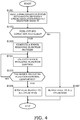
FIG. 4 is a flowchart illustrating a flow of fuel cut control according to an embodiment of the present invention; -
FIG. 5A illustrates a trend of an injection stop cylinder number setting map in the fuel cut control; -
FIG. 5B illustrates a trend of an injection execute cylinder number setting map in the fuel cut control; -
FIG. 6 illustrates a summary of shock reducing injection control in the fuel cut control; -
FIG. 7 illustrates an operation of an engine controller concerning the shock reducing injection control under reference conditions; -
FIG. 8 illustrates an operation of the engine controller concerning the shock reducing injection control when the engine revolution speed is higher than in the reference conditions; -
FIG. 9 illustrates an operation of the engine controller concerning the shock reducing injection control when the reduction ratio is lower than in the reference conditions; -
FIG. 10 is a flowchart illustrating a flow of fuel cut recovery control according to another embodiment of the present invention; -
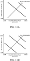
FIG. 11A illustrates a trend of an injection stop cylinder number setting map in the fuel cut recovery control; -
FIG. 11B illustrates a trend of an injection execute cylinder number setting map in the fuel cut recovery control; -
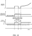
FIG. 12 illustrates a summary of shock reducing injection control in the fuel cut recovery control; -
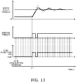
FIG. 13 illustrates an operation of the engine controller concerning the shock reducing injection control under reference conditions; -
FIG. 14 illustrates an operation of the engine controller concerning the shock reducing injection control when the engine revolution speed is higher than in the reference conditions; and -
FIG. 15 illustrates an operation of the engine controller concerning the shock reducing injection control when the reduction ratio is lower than in the reference conditions. - Embodiments of the present invention will be described below with reference to the drawings.
-
FIG. 1 shows an overall configuration of a vehicle drive system that includes an internal combustion engine (hereinafter, referred to as "engine") 1 according to a first embodiment of the present invention. - In the present embodiment, the
engine 1 constitutes a vehicle drive source. A torque generated by theengine 1 is transmitted via a transmission 3 (described later), afinal gear 4, and a differential gear 5, to driveshafts drive wheels transmission 3 in the present embodiment, not limited thereto, a stepped transmission may be adopted as well. - The
engine 1 includes anintake passage 11 and anexhaust passage 12. The air is sucked into the cylinders via theintake passage 11, and the exhaust gas generated by combustion within the cylinders is discharged to the outside via theexhaust passage 12. In the present embodiment, theengine 1 includesfuel injection valves 13 at a port of theintake passage 11, and air-fuel mixture of the air and the fuel injected by thefuel injection valves 13 is sucked into the cylinders. Thefuel injection valves 13 are not limited to those which inject fuel to the port of theintake passage 11; they may be ones that inject fuel directly into the cylinders. A spark plug (not shown) is provided for each cylinder, at a cylinder head of theengine 1, and the air-fuel mixture sucked in the cylinder is ignited by this spark plug. - The
engine 1 has acrankshaft 15 connected to an input shaft (hereinafter, referred to as "transmission input shaft") 31 of thetransmission 3 via aclutch 2. Thetransmission 3 includes, as shift control elements, an input side pulley, an output side pulley, and a metal belt suspended between the pulleys. A ratio between the metal belt winding diameter on the input side pulley and that on the output side pulley can be changed so as to change the reduction ratio. Theclutch 2 is a torque converter lock-up clutch. Thetransmission 3 has an output shaft (hereinafter, referred to as "transmission output shaft") 32 connected to thedrive shafts final gear 4 and the differential gear 5. The output torque (engine torque) of theengine 1 transmitted via thetransmission 3 and thefinal gear 4 to thedrive shafts drive wheels - The operation of the
engine 1 is controlled by anengine controller 101. - The
engine controller 101 is constituted as an electronic control unit, which includes a central processing unit (CPU), storage devices such as ROM and RAM, and an input/output interface. - The
engine controller 101 inputs, as the operating states of theengine 1, detection signals of anaccelerator sensor 111, arevolution speed sensor 112, and acoolant temperature sensor 113, and also inputs detection signals of anair flow meter 114, avehicle speed sensor 115, and an air-fuel ratio sensor 116. - The
accelerator sensor 111 detects a driver's accelerator pedal depression amount (hereinafter, referred to as "accelerator operation amount") APO. Therevolution speed sensor 112 detects a revolution speed NE of theengine 1. As therevolution speed sensor 112, a crank angle sensor may be adopted. A signal output from the crank angle sensor for each unit crank angle or each reference crank angle is converted to the number of revolutions per unit time (hereinafter, referred to as "engine revolution speed"), to detect the revolution speed NE of theengine 1. Thecoolant temperature sensor 113 detects a temperature TW of engine coolant. Instead of the temperature of the engine coolant, a temperature of engine lubricant oil may be adopted. Theair flow meter 114 detects a flow rate of the air sucked into a cylinder, as an intake air quantity Qa. Thevehicle speed sensor 115 detects a running speed VSP of the vehicle. The air-fuel ratio sensor 116 detects an air-fuel ratio AF of the exhaust gas. Theengine controller 101 sets a fuel injection quantity, an ignition timing, and the like on the basis of the detection signals of thesensors 111 to 116, and outputs a drive signal according to the fuel injection quantity to thefuel injection valves 13, for example, to control the operation of theengine 1. - In the present embodiment, in addition to the above, for performing deceleration fuel cut during traveling, an
idle switch 117 is provided which outputs an ON signal when the accelerator is fully closed. Theidle switch 117 outputs an ON signal in the state where the accelerator pedal is fully released. The signal from theidle switch 117 is input to theengine controller 101 similarly as the signals from the other sensors. In normal times, theengine controller 101 outputs a drive signal according to the operating states of theengine 1 to thefuel injection valves 13, as explained above. On the other hand, in a case where a predetermined fuel cut condition, including that the engine revolution speed NE is not lower than a predetermined value NEfc, is fulfilled at a time when the accelerator is fully closed, the injection operation of thefuel injection valves 13 is stopped, to stop fuel supply to theengine 1. The deceleration fuel cut is cancelled, following the execution thereof, when the driver depresses the accelerator pedal and the output from theidle switch 117 changes to an OFF signal, or when the engine revolution speed NE decreases to or below a predetermined value NErc with the accelerator pedal remained in the fully released state. After the cancellation of the deceleration fuel cut, the injection operation of thefuel injection valves 13 is restarted, whereby the fuel supply to theengine 1 is restarted. - The
engine controller 101 constitutes the "engine controlling unit" according to the present embodiment, andvarious sensors 111 to 116 including theaccelerator sensor 111 and therevolution speed sensor 112 constitute the "engine operating state sensor". - The operation of the
transmission 3 is controlled by atransmission controller 301 which is constituted as an electronic control unit similarly as theengine controller 101. - The
transmission controller 301 inputs a signal from arevolution speed sensor 311 which detects a revolution speed of thetransmission input shaft 31, as well as a signal from an inhibitor switch (not shown) and a signal from a fluid temperature sensor which detects a temperature of transmission hydraulic fluid, and further inputs the accelerator operation amount APO and the vehicle speed VSP via theengine controller 101. On the basis of the detection signals of the sensors, thetransmission controller 301 performs computation regarding shift control and the like, and controls the operations of thetransmission 3 and the lock-upclutch 2. - Specifically, the
transmission controller 301 refers to the trend map data shown inFIG. 2 , on the basis of the accelerator operation amount APO and the vehicle speed VSP, to calculate a target input shaft revolution speed Ni_t of thetransmission 3. The target input shaft revolution speed Ni_t is a target value for the revolution speed (hereinafter, referred to as "input shaft revolution speed ") Ni of thetransmission input shaft 31, which is set in accordance with the vehicle speed VSP for every accelerator operation amount APO, such that it is increased in response to the increase of the vehicle speed VSP and, with a constant vehicle speed VSP, it is set to a greater value with greater accelerator operation amount APO. Thetransmission controller 301 controls the reduction ratio of thetransmission 3 to cause the input shaft revolution speed Ni detected by therevolution speed sensor 311 to approach the target input shaft revolution speed Ni_t. Further, thetransmission controller 301 refers to the trend map data shown inFIG. 3 and, in a case where the vehicle running condition determined by the accelerator operation amount APO and the vehicle speed VSP falls within a lock-up range in the figure, causes the lock-upclutch 2 to be engaged, whereas in a case where it falls within another range, causes the lock-upclutch 2 to be disengaged. In the state where the lock-upclutch 2 is engaged, thecrankshaft 15 of theengine 1 and theinput shaft 31 of thetransmission 3 are mechanically coupled directly to each other. - Fuel cut control for performing deceleration fuel cut will be described with reference to the flowchart shown in
FIG. 4 . - In the present embodiment, the control routine shown in
FIG. 4 is carried out at certain time intervals after start of theengine 1. In the following description, it is assumed, in performing the deceleration fuel cut, that the vehicle running condition falls within the lock-up range shown inFIG. 3 and that the lock-upclutch 2 is in the engaged state. - In S101, as the operating states of the
engine 1, an engine revolution speed NE and a reduction ratio RT are read, and a signal from theidle switch 117 is also read. Here, the reduction ratio RT refers to a reduction ratio over the entire power transmission path from theengine 1 to thedrive wheels crankshaft 15 of theengine 1 to thedrive shafts transmission 3 and a final reduction ratio R2 at thefinal gear 4. Although the reduction ratio R1 at thetransmission 3 may be set to a target reduction ratio of thetransmission 3 and the reduction ratio RT may be obtained as a product of this target reduction ratio and the final reduction ratio R2, in the present embodiment, a value obtained by dividing the revolution speed Ni of thetransmission input shaft 31 by a revolution speed No of thedrive shafts drive shafts - In S102, it is determined whether a predetermined fuel cut condition has been fulfilled. Specifically, it is determined whether the signal from the
idle switch 117 is an ON signal and the engine revolution speed NE is not lower than a predetermined value NEfc. If the fuel cut condition is fulfilled, the process proceeds to S103; otherwise, the process proceeds to S107. The fuel cut condition corresponds to the "predetermined fuel supply stop condition". In the present embodiment, the state where the accelerator pedal is fully released is determined by the signal from theidle switch 117. Alternatively, theaccelerator sensor 111 may be adopted to detect the state where the accelerator pedal is fully released, with the accelerator operation amount APO being zero or substantially zero. - In S103 to 105, shock reducing injection control at a time of stopping fuel supply (hereinafter, referred to as "stop time shock reducing injection control") is carried out. The stop time shock reducing injection control corresponds to the "stop time vibration suppression control", in which after the stop of fuel supply in response to fulfillment of the fuel cut condition, fuel supply to some of the cylinders is performed to reduce the torque shock due to the torsional vibration in the drive train.
-
FIG. 6 shows a specific example of a stop time shock reducing injection pattern. - In the present embodiment, the stop time shock reducing injection pattern is set over times tc1 to tc3 where a predetermined number of cylinders undergo a combustion stroke following the time tc1 when the fuel cut condition is fulfilled. According to this pattern, driving of the
fuel injection valve 13 is permitted (fuel injection ON) or inhibited (fuel injection OFF). The engine revolution speed NE and the reduction ratio RT at time tc1 are detected, and on the basis of these engine operating states, the number (hereinafter, referred to as "injection stop cylinder number") NcyO of cylinders in which driving of thefuel injection valve 13 is inhibited and the number (hereinafter, referred to as "injection execute cylinder number") Ncy1 of cylinders in which driving of thefuel injection valve 13 is permitted are set. - In the example shown in
FIG. 6 , the injection stop cylinder number NcyO is 3 and the injection execute cylinder number Ncy1 is 2. Three consecutive cylinders in order of ignition (third cylinder # 3,fourth cylinder # 4, and second cylinder #2), led by thethird cylinder # 3 that is to undergo a combustion stroke next after the time tc1 when the fuel cut condition is fulfilled, are set to be the targets in which driving of thefuel injection valve 13 is inhibited. Further, the targets in which driving of thefuel injection valve 13 is permitted are set to be two consecutive cylinders in order of ignition (first cylinder # 1 and third cylinder #3) following the last target cylinder (second cylinder #2) in which driving of the valve was inhibited. - In this manner, after the stop of fuel supply in response to fulfillment of the fuel cut condition (time tc1), driving of the
fuel injection valve 13 is permitted in some of the cylinders (first andthird cylinders # 1 and #3), so that an engine torque is generated temporarily (times tc2 to tc3). - Returning to
FIG. 4 , in S103, a stop time shock reducing injection pattern for reducing the torque shock at a time of stopping fuel supply is computed. Specifically, the injection stop cylinder number NcyO and the injection execute cylinder number Ncy1 are computed. Computation of the injection stop cylinder number NcyO is performed, on the basis of the engine revolution speed NE and the reduction ratio RT, by referring to the trend map data shown inFIG. 5A . With this computation, the injection stop cylinder number NcyO is calculated to be a greater value as the engine revolution speed NE is higher and the reduction ratio RT is higher (in other words, as the gear stage is in a lower speed side). Computation of the injection execute cylinder number Ncy1 is similarly performed, on the basis of the engine revolution speed NE and the reduction ratio RT, by referring to the map data shown inFIG. 5B . The injection execute cylinder number Ncy1 is calculated to be a greater value as the engine revolution speed NE is higher and the reduction ratio RT is higher. - In S104, the
fuel injection valves 13 are driven in accordance with the stop time shock reducing injection pattern. In the example shown inFIG. 6 , fuel supply to theengine 1 is stopped in response to fulfillment of the fuel cut condition (time tc1), and it is determined whether thecylinders # 3, #4, and #2 corresponding to the injection stop cylinder number NcyO (=3) arranged in order of ignition, led by the cylinder (third cylinder #3) that undergoes a combustion stroke next after the fulfillment of the fuel cut condition, have undergone a combustion stroke. When these cylinders have undergone the combustion stroke, driving of thefuel injection valve 13 is permitted in the cylinders (#1 and #3) corresponding to the injection execute cylinder number Ncy1 (=2) arranged in order of ignition following thesecond cylinder # 2, to temporarily perform fuel supply to theengine 1. - In S105, it is determined whether the stop time shock reducing injection control has been completed. Specifically, it is determined whether a number of (in the example shown in
FIG. 6 , five) cylinders, the number being obtained as a sum (=Ncy0+Ncy1) of the injection stop cylinder number NcyO and the injection execute cylinder number Ncy1, have undergone a combustion stroke. When the stop time shock reducing injection control is completed, the process proceeds to S106; otherwise, the process returns to S104, and the processing in S104 and 105 described above is repeated. - In S106, driving of the
fuel injection valves 13 included in all the cylinders is inhibited, whereby fuel supply to theengine 1 is fully stopped, to complete the fuel cut control. - In S107, normal fuel injection control is executed, in which fuel of the quantity corresponding to the engine operating states is supplied to the
engine 1 by thefuel injection valves 13. - In the present embodiment, the processing in S103 to 105 shown in the flowchart in
FIG. 4 corresponds to the "stop time vibration suppression control", and the injection stop cylinder number NcyO and the injection execute cylinder number Ncy1 correspond respectively to the "first predetermined number" and the "second predetermined number". Further, the processing in S102 shown in the flowchart inFIG. 4 implements the function as the "stop condition determining unit", the processing in S103 to 105 implements the function as the "stop time vibration suppression controlling unit", and the processing in S106 implements the function as the "fuel supply stopping unit". - The above is the content of the fuel cut control. Effects obtained by the present embodiment will be summarized below.
- In the present embodiment, in performing the deceleration fuel cut, the stop time shock reducing injection control is carried out before stopping fuel supply to all the cylinders, to thereby suppress torsional vibration in the drive train due to the fluctuation of the engine torque, and reduce the torque shock.
-
FIG. 7 shows effects according to the present embodiment under reference conditions (engine revolution speed: NEb1, reduction ratio: RTb1). InFIG. 7 , the two-dot-dashed line indicates a drive shaft torque in a case where fuel supply to all the cylinders is stopped immediately after fulfillment of the fuel cut condition (time tc1), without executing the stop time shock reducing injection control, and the solid line indicates the one in a case where the stop time shock reducing injection control is executed. - When fuel supply to the
engine 1 is temporarily performed after the stop of fuel supply, by the stop time shock reducing injection control, to generate an engine torque in agreement with the negative peak of the fluctuation occurring in the drive shaft torque, the fluctuation of the drive shaft torque can be suppressed, and the torque shock can be reduced. In the example shown inFIG. 7 , for convenience of illustration, the injection stop cylinder number NcyO is set to 2 and the injection execute cylinder number Ncy1 is set to 1. - In the present embodiment, it has been configured such that the injection stop cylinder number NcyO and the injection execute cylinder number Ncy1 can both be set variably in accordance with the engine revolution speed NE and the reduction ratio RT. Specifically, on the basis of the engine revolution speed NE and the reduction ratio RT at the time of fulfillment of the fuel cut condition, the injection stop cylinder number NcyO is set to a greater value as the engine revolution speed NE is higher and the reduction ratio RT is higher, and the injection execute cylinder number Ncy1 is also set to a greater value as the engine revolution speed NE is higher and the reduction ratio RT is higher.
-
FIG. 8 illustrates a stop time shock reducing injection pattern which is set when the fuel cut condition is fulfilled in a state where the engine revolution speed NE is higher (NE=2×NEb1) than in the reference conditions. Of the two solid lines, the narrow solid line A indicates a change in a case where the injection stop cylinder number NcyO and the injection execute cylinder number Ncy1 are set to 2 and 1, respectively, as in the settings in the reference conditions, and the bold solid line B indicates the one in a case where the injection stop cylinder number NcyO and the injection execute cylinder number Ncy1 are set in accordance with the engine revolution speed NE. In the example shown inFIG. 8 , the injection stop cylinder number NcyO and the injection execute cylinder number Ncy1 are both increased (Ncy0=4, Ncy1=2) in response to the increase in the engine revolution speed NE. - The time resolution with which the engine torque can be controlled is determined by the combustion intervals between the cylinders that are consecutive in order of ignition. The combustion interval (time) becomes shorter with increasing engine revolution speed NE. Thus, if the injection stop cylinder number NcyO and the injection execute cylinder number Ncy1 are kept at the settings in the reference conditions despite the higher engine revolution speed NE, the engine torque will be generated at a timing earlier than the negative peak in the fluctuation occurring in the drive shaft torque, and further, the engine torque will be generated only during a short period of time as compared to the period in which negative components are formed in the fluctuation of the drive shaft torque.
- In contrast, when the injection stop cylinder number NcyO and the injection execute cylinder number Ncy1 are increased in response to the increase of the engine revolution speed NE, an engine torque can be generated at an appropriate timing that agrees with the negative peak in the fluctuation occurring in the drive shaft torque, and the engine torque can also be generated over an appropriate period of time with respect to the period in which negative components are formed in the fluctuation of the drive shaft torque. It is therefore possible to more appropriately suppress the fluctuation of the drive shaft torque, and reduce the torque shock.
-
FIG. 9 illustrates a stop time shock reducing injection pattern which is set when the fuel cut condition is fulfilled in a state where the reduction ratio RT is lower (RT=RTb1/3) than in the reference conditions. Similarly as inFIG. 8 , of the two solid lines, the narrow solid line A indicates a change in a case where the settings in the reference conditions are kept unchanged (Ncy0=2, Ncy1=1), and the bold solid line B indicates the one in a case where the injection stop cylinder number NcyO and the injection execute cylinder number Ncy1 are set in accordance with the reduction ratio RT. In the example shown inFIG. 9 , while the injection execute cylinder number Ncy1 is kept at the setting in the reference conditions, the injection stop cylinder number NcyO is decreased in response to the decrease of the reduction ratio RT (Ncy0=1, Ncy1=1). - The torsional vibration occurring in the drive train due to the engine torque fluctuation varies depending on the reduction ratio RT. With a constant engine revolution speed NE, the cycle of fluctuation of the drive shaft torque becomes shorter as the reduction ratio RT decreases (in other words, as the gear stage is in a higher speed side). Therefore, if the injection stop cylinder number NcyO is kept at the setting in the reference conditions despite the lower reduction ratio RT, the engine torque will be generated behind the negative peak in the fluctuation occurring in the drive shaft torque.
- In contrast, when the injection stop cylinder number NcyO is decreased in response to the decrease of the reduction ratio RT to cause the engine torque to be generated at an earlier timing after the stop of the fuel supply, the engine torque can be generated at an appropriate timing in agreement with the negative peek in the fluctuation occurring in the drive shaft torque.
- Further, while the amplitude of the drive shaft torque decreases with decreasing reduction ratio RT, if the injection execute cylinder number Ncy1 is kept at the setting in the reference conditions despite the decreased reduction ratio RT, an excessively large engine torque will be generated, which may rather increase the fluctuation of the drive shaft torque.
- In contrast, when the injection execute cylinder number is decreased in response to the decrease of the reduction ratio RT, an engine torque of an appropriate magnitude can be superposed on the drive shaft torque. It is therefore possible to more appropriately suppress the fluctuation of the drive shaft torque, and reduce the torque shock.
- A second embodiment of the present invention will now be described.
- In the present embodiment, fuel cut recovery control of restarting fuel supply to the
engine 1 following the execution of the deceleration fuel cut is carried out. -
FIG. 10 is a flowchart illustrating a flow of the fuel cut recovery control. - In S201, as the operating states of the
engine 1, an engine revolution speed NE and a reduction ratio RT are read, and a signal from theidle switch 117 is also read. - In S202, it is determined whether a predetermined fuel cut recovery condition has been fulfilled. Specifically, it is determined whether the signal from the
idle switch 117 has been changed from an ON signal to an OFF signal, or the engine revolution speed NE has decreased to or below a predetermined value NErc with the signal from theidle switch 117 still being an ON signal. If the fuel cut recovery condition is fulfilled, the process proceeds to S203; otherwise, the process proceeds to S207. The fuel cut recovery condition corresponds to the "predetermined fuel supply restart condition". - In S203 to 205, shock reducing injection control at a time of restarting fuel supply (hereinafter, referred to as "restart time shock reducing injection control") is carried out. The restart time shock reducing injection control is for reducing the torque shock due to the torsional vibration in the drive train by stopping fuel supply to some of the cylinders following the restart of fuel supply in response to fulfillment of the fuel cut recovery condition.
-
FIG. 12 illustrates a specific example of a restart time shock reducing injection pattern. - In the present embodiment, the restart time shock reducing injection pattern is set over times tr1 to tr3 during which a predetermined number of cylinders undergo a combustion stroke after the time tr1 when the fuel cut recovery condition is fulfilled. Driving of the
fuel injection valves 13 is permitted (fuel injection ON) or inhibited (fuel injection OFF) in accordance with this pattern. As in the case of setting the stop time shock reducing injection pattern, the engine revolution speed NE and the reduction ratio RT at time tr1 are detected, and the injection execute cylinder number Ncy1 and the injection stop cylinder number NcyO are set on the basis of these engine operating states. - In the example shown in
FIG. 12 , the injection execute cylinder number Ncy1 is 3, and the injection stop cylinder number NcyO is 2. Three consecutive cylinders in order of ignition (second cylinder # 2,first cylinder # 1, and third cylinder #3), led by thesecond cylinder # 2 that is to undergo a combustion stroke next after the time tr1 when the fuel cut recovery condition is fulfilled, are set to be the targets in which driving of thefuel injection valve 13 is permitted. Further, the targets in which driving of thefuel injection valve 13 is inhibited are set to be two consecutive cylinders in order of ignition (fourth cylinder # 4 and second cylinder #2) following the last target cylinder (third cylinder #3) in which driving of the valve was permitted. - In this manner, after the restart of fuel supply in response to fulfillment of the fuel cut recovery condition (time tr1), driving of the
fuel injection valve 13 is inhibited in some cylinders (fourth andsecond cylinders # 4, #2), so that the engine torque is reduced temporarily (times tr2 to tr3). - Returning to
FIG. 10 , in S203, a restart time shock reducing injection pattern for reducing the torque shock at the time of restarting fuel supply is computed. Specifically, the injection execute cylinder number and the injection stop cylinder number NcyO are computed. Computation of the injection stop cylinder number NcyO is carried out by referring to the trend map data shown inFIG. 11A in accordance with the engine revolution speed NE and the reduction ratio RT. With this computation, the injection stop cylinder number NcyO is calculated to be a larger value as the engine revolution speed NE is higher and the reduction ratio RT is higher (in other words, as the gear stage is in a lower speed side). Computation of the injection execute cylinder number Ncy1 is similarly carried out by referring to the map data shown inFIG. 11B , in accordance with the engine revolution speed NE and the reduction ratio RT. The injection execute cylinder number Ncy1 is calculated to be a larger value as the engine revolution speed NE is higher and the reduction ratio RT is higher. - In S204, the
fuel injection valves 13 are driven in accordance with the restart time shock reducing injection pattern. In the example shown inFIG. 12 , fuel supply to theengine 1 is restarted in response to fulfillment of the fuel cut recovery condition (time tr1), and it is determined whether thecylinders # 2, #1, and #3 corresponding to the injection execute cylinder number Ncy1 (=3) arranged in order of ignition, led by the cylinder (second cylinder #2) that undergoes a combustion stroke next after the fulfillment of the fuel cut recovery condition, have undergone a combustion stroke, or stated differently, it is determined whether fuel supply to the cylinders corresponding to the injection execute cylinder number Ncy1 has finished. When the fuel supply to these cylinders has finished, driving of thefuel injection valve 13 is inhibited in the cylinders (#4 and #2) corresponding to the injection stop cylinder number NcyO (=2) arranged in order of ignition following thethird cylinder # 3, to temporarily stop fuel supply to theengine 1. - In step S205, it is determined whether the restart time shock reducing injection control has been completed. Specifically, it is determined whether a number of (in the example shown in
FIG. 12 , five) cylinders, the number being obtained as a sum (=Ncy1+Ncy0) of the injection execute cylinder number Ncy1 and the injection stop cylinder number NcyO, have undergone a combustion stroke. When the restart time shock reducing injection control is completed, the process proceeds to S206; otherwise, the process returns to S204, and the processing in S204 and 205 explained above is repeated. - In S206, driving of the
fuel injection valves 13 included in all the cylinders is permitted, to resume the fuel supply to theengine 1. The fuel cut recovery control is thus completed. - In S207, the deceleration fuel cut is continued, with the fuel supply to the
engine 1 being stopped. - In the present embodiment, the injection execute cylinder number Ncy1 and the injection stop cylinder number NcyO correspond to the "third predetermined number" and the "fourth predetermined number", respectively. Further, the processing in S202 shown in the flowchart in
FIG. 10 implements the function as the "restart condition determining unit", and the processing in S203 to 205 implements the function as the "restart time vibration suppression controlling unit". - The above is the content of the fuel cut recovery control. Effects obtained by the present embodiment will be summarized below.
- In the present embodiment, in restarting fuel supply by the fuel cut recovery control, the restart time shock reducing injection control is carried out after the restart of fuel supply, to temporarily stop the fuel supply to the
engine 1, to thereby suppress the torsional vibration in the drive train due to the fluctuation of the engine torque, and reduce the torque shock. -
FIG. 13 shows effects according to the present embodiment under reference conditions (engine revolution speed: NEb2, reduction ratio: RTb2). InFIG. 13 , the two-dot-dashed line indicates a drive shaft torque in a case where, after the restart of fuel supply (time tr1), fuel supply is continued without a temporary stop, without executing the restart time shock reducing injection control, and the solid line indicates the one in a case where the restart time shock reducing injection control is executed. - When fuel supply to the
engine 1 is temporarily stopped, following the restart of fuel supply, by the restart time shock reducing injection control to decrease the engine torque in agreement with the positive peak in the fluctuation occurring in the drive shaft torque, an excessive increase of the drive shaft torque can be suppressed, and the torque shock can be reduced. - In the present embodiment, it has been configured such that the injection execute cylinder number Ncy1 and the injection stop cylinder number NcyO can both be set variably in accordance with the engine revolution speed NE and the reduction ratio RT.
-
FIG. 14 illustrates a restart time shock reducing injection pattern which is set when the fuel cut recovery condition is fulfilled in a state where the engine revolution speed NE is higher (NE=2×NEb2) than in the reference conditions. Similarly as inFIG. 13 , the two-dot-dashed line indicates a drive shaft torque in a case where no restart time shock reducing injection control is executed, and the solid line indicates the one in a case where the restart time shock reducing injection control is executed. - In the example shown in
FIG. 14 , with the increase of the engine revolution speed NE, the injection execute cylinder number Ncy1 and the injection stop cylinder number NcyO are increased (Ncy1=4, Ncy0=2) from the settings in the reference conditions. If the injection execute cylinder number Ncy1 and the injection stop cylinder number NcyO are kept at the settings in the reference conditions (Ncy1=2, Ncy0=1) despite the higher engine revolution speed NE, with the combustion interval (time) shortened, the engine torque will decease at a timing earlier than the positive peak in the fluctuation occurring in the drive shaft torque, and the engine torque will decrease only during a short period of time as compared to the period in which positive components are formed in the fluctuation of the drive shaft torque. - In contrast, when the injection execute cylinder number Ncy1 and the injection stop cylinder number NcyO are increased in response to the increase of the engine revolution speed NE, the engine torque can be decreased at an appropriate timing in agreement with the positive peak in the fluctuation occurring in the drive shaft torque, and the engine torque can be decreased over an appropriate period of time with respect to the period in which positive components are formed in the fluctuation of the drive shaft torque. It is therefore possible to more appropriately suppress the fluctuation of the drive shaft torque and reduce the torque shock.
-
FIG. 15 illustrates a restart time shock reducing injection pattern which is set when the fuel cut recovery condition is fulfilled in a state where the reduction ratio RT is lower (RT=RTb2/3) than in the reference conditions. - In the example shown in
FIG. 15 , while the injection stop cylinder number NcyO is kept at the setting (Ncy0=1) in the reference conditions, the injection execute cylinder number is decreased (Ncy1=1) in response to the decrease of the reduction ratio RT. If the injection execute cylinder number Ncy1 is kept at the setting (Ncy1=2) in the reference conditions despite the lower reduction ratio RT, with the shortened cycle of fluctuation of the drive shaft torque, the engine torque will decrease behind the positive peak in the fluctuation occurring in the drive shaft torque. - In contrast, when the injection execute cylinder number is decreased with the decrease of the reduction ratio RT to make the engine torque decreased at an earlier timing after the restart of the fuel supply, it is possible to reduce the engine torque at an appropriate timing in agreement with the positive peak in the fluctuation occurring in the drive shaft torque.
- Further, while the amplitude of the drive shaft torque decreases with decreasing reduction ratio RT, if the injection stop cylinder number NcyO is kept at the setting in the reference conditions despite the decrease of the reduction ratio RT, the engine torque may decrease excessively, possibly causing unnecessary drop of the drive shaft torque.
- In contrast, when the injection stop cylinder number NcyO is decreased in response to the decrease of the reduction ratio RT, the fluctuation of the drive shaft torque can be suppressed appropriately, and it is therefore possible to reduce the torque shock while securing a large enough drive shaft torque.
- Although a description has been given above of the embodiments of the present invention, the embodiments show only some application examples of the present invention, and are not intended to limit the technical scope of the present invention to the specific configurations in the embodiments.
Claims (10)
- A control method for an engine, comprising:determining whether a predetermined fuel supply stop condition has been fulfilled;executing stop time vibration suppression control of, after stop of fuel supply in response to fulfillment of the predetermined fuel supply stop condition, temporarily performing fuel supply to the engine to suppress vehicle vibration; andstopping fuel supply to all cylinders after the execution of the stop time vibration suppression control; whereinthe stop time vibration suppression control includesdetermining whether a first predetermined number of cylinders have undergone a combustion stroke after the stop of the fuel supply, the first predetermined number being according to an engine revolution speed or a reduction ratio from the engine to drive wheels, andin a case where the first predetermined number of cylinders have undergone the combustion stroke, performing fuel supply to a second predetermined number of cylinders, andthe first predetermined number isincreased as the engine revolution speed is higher, andincreased as the reduction ratio from the engine to the drive wheels is higher.
- The engine control method according to claim 1, wherein
the second predetermined number is
increased as the engine revolution speed is higher, and
increased as the reduction ratio from the engine to the drive wheels is higher. - A control method for an engine, comprising:determining whether a predetermined fuel supply stop condition has been fulfilled;executing stop time vibration suppression control of, after stop of fuel supply in response to fulfillment of the predetermined fuel supply stop condition, temporarily performing fuel supply to the engine to suppress vehicle vibration; andstopping fuel supply to all cylinders after the execution of the stop time vibration suppression control; whereinthe stop time vibration suppression control includesdetermining whether a first predetermined number of cylinders have undergone a combustion stroke after the stop of the fuel supply, andin a case where the first predetermined number of cylinders have undergone the combustion stroke, performing fuel supply to a second predetermined number of cylinders, the second predetermined number being according to an engine revolution speed or a reduction ratio from the engine to drive wheels, andthe second predetermined number isincreased as the engine revolution speed is higher, andincreased as the reduction ratio from the engine to the drive wheels is higher.
- The engine control method according to any one of claims 1 to 3, comprising:after the stop of the fuel supply, determining whether a predetermined fuel supply restart condition has been fulfilled;restarting fuel supply to the engine after fulfillment of the predetermined fuel supply restart condition;determining whether a third predetermined number of cylinders have undergone a combustion stroke after the restart of the fuel supply, the third predetermined number being according to the engine revolution speed or the reduction ratio from the engine to the drive wheels; andin a case where the third predetermined number of cylinders have undergone the combustion stroke, stopping fuel supply to a fourth predetermined number of cylinders; whereinthe third predetermined number isincreased as the engine revolution speed is higher, andincreased as the reduction ratio from the engine to the drive wheels is higher.
- The engine control method according to claim 4, wherein
the fourth predetermined number is
increased as the engine revolution speed is higher, and
increased as the reduction ratio from the engine to the drive wheels is higher. - The engine control method according to any one of claims 1 to 3, comprising:after the stop of the fuel supply, determining whether a predetermined fuel supply restart condition has been fulfilled;restarting fuel supply to the engine after fulfillment of the predetermined fuel supply restart condition;determining whether a third predetermined number of cylinders have undergone a combustion stroke after the restart of the fuel supply; andin a case where the third predetermined number of cylinders have undergone the combustion stroke, stopping fuel supply to a fourth predetermined number of cylinders, the fourth predetermined number being according to the engine revolution speed or the reduction ratio from the engine to the drive wheels; whereinthe fourth predetermined number isincreased as the engine revolution speed is higher, andincreased as the reduction ratio from the engine to the drive wheels is higher.
- A control device for an engine, comprising:a fuel injection valve configured to supply fuel to the engine;an engine operating state sensor configured to detect an operating state of the engine; andan engine controlling unit configured to control an engine torque on the basis of the operating state of the engine,the engine controlling unit havinga stop condition determining unit configured to determine whether a predetermined fuel supply stop condition has been fulfilled,a stop time vibration suppression controlling unit configured to, after stop of fuel supply in response to fulfillment of the predetermined fuel supply stop condition, temporarily perform fuel supply to the engine to suppress vehicle vibration, anda fuel supply stopping unit configured to stop fuel supply to every cylinder by the fuel injection valve after the performance of the temporary fuel supply, whereinthe stop time vibration suppression controlling unit is configured todetermine whether a first predetermined number of cylinders have undergone a combustion stroke after the stop of the fuel supply, the first predetermined number being according to an engine revolution speed or a reduction ratio from the engine to drive wheels, andin a case where the first predetermined number of cylinders have undergone the combustion stroke, perform fuel supply to a second predetermined number of cylinders, andthe first predetermined number isincreased as the engine revolution speed is higher andincreased as the reduction ratio from the engine to the drive wheels is higher.
- A control device for an engine, comprising:a fuel injection valve configured to supply fuel to the engine;an engine operating state sensor configured to detect an operating state of the engine; andan engine controlling unit configured to control an engine torque on the basis of the operating state of the engine,the engine controlling unit havinga stop condition determining unit configured to determine whether a predetermined fuel supply stop condition has been fulfilled,a stop time vibration suppression controlling unit configured to, after stop of fuel supply in response to fulfillment of the predetermined fuel supply stop condition, temporarily perform fuel supply to the engine to suppress vehicle vibration, anda fuel supply stopping unit configured to stop fuel supply to every cylinder by the fuel injection valve after the performance of the temporary fuel supply, whereinthe stop time vibration suppression controlling unit is configured todetermine whether a first predetermined number of cylinders have undergone a combustion stroke after the stop of the fuel supply, andin a case where the first predetermined number of cylinders have undergone the combustion stroke, perform fuel supply to a second predetermined number of cylinders, the second predetermined number being according to an engine revolution speed or a reduction ratio from the engine to drive wheels, andthe second predetermined number isincreased as the engine revolution speed is higher andincreased as the reduction ratio from the engine to the drive wheels is higher.
- The engine control device according to claim 7 or 8, wherein
the engine controlling unit has
a restart condition determining unit configured to determine whether a predetermined fuel supply restart condition has been fulfilled after the stop of the fuel supply, and
a restart time vibration suppression controlling unit configured to, after restart of the fuel supply in response to fulfillment of the predetermined fuel supply restart condition, temporarily stop fuel supply to the engine to suppress vehicle vibration,
the restart time vibration suppression controlling unit is configured to
determine whether a third predetermined number of cylinders have undergone a combustion stroke after the restart of the fuel supply, the third predetermined number being according to the engine revolution speed or the reduction ratio from the engine to the drive wheels, and
in a case where the third predetermined number of cylinders have undergone the combustion stroke, stop fuel supply to a fourth predetermined number of cylinders, and
the third predetermined number is
increased as the engine revolution speed is higher and
increased as the reduction ratio from the engine to the drive wheels is higher. - The engine control device according to claim 7 or 8, wherein
the engine controlling unit has
a restart condition determining unit configured to determine whether a predetermined fuel supply restart condition has been fulfilled after the stop of the fuel supply, and
a restart time vibration suppression controlling unit configured to, after restart of the fuel supply in response to fulfillment of the predetermined fuel supply restart condition, temporarily stop fuel supply to the engine to suppress vehicle vibration,
the restart time vibration suppression controlling unit is configured to
determine whether a third predetermined number of cylinders have undergone a combustion stroke after the restart of the fuel supply, and
in a case where the third predetermined number of cylinders have undergone the combustion stroke, stop fuel supply to a fourth predetermined number of cylinders, the fourth predetermined number being according to the engine revolution speed or the reduction ratio from the engine to the drive wheels, and
the fourth predetermined number is
increased as the engine revolution speed is higher and
increased as the reduction ratio from the engine to the drive wheels is higher.
Applications Claiming Priority (1)
| Application Number | Priority Date | Filing Date | Title |
|---|---|---|---|
| PCT/JP2016/077569 WO2018051513A1 (en) | 2016-09-16 | 2016-09-16 | Control method and control device for engine |
Publications (3)
| Publication Number | Publication Date |
|---|---|
| EP3514353A1 true EP3514353A1 (en) | 2019-07-24 |
| EP3514353A4 EP3514353A4 (en) | 2019-09-25 |
| EP3514353B1 EP3514353B1 (en) | 2021-03-03 |
Family
ID=61618734
Family Applications (1)
| Application Number | Title | Priority Date | Filing Date |
|---|---|---|---|
| EP16916293.0A Active EP3514353B1 (en) | 2016-09-16 | 2016-09-16 | Control method and control device for engine |
Country Status (8)
| Country | Link |
|---|---|
| US (1) | US10597038B2 (en) |
| EP (1) | EP3514353B1 (en) |
| JP (1) | JP6673488B2 (en) |
| CN (1) | CN109790786B (en) |
| BR (1) | BR112019005119B1 (en) |
| MX (1) | MX376403B (en) |
| RU (1) | RU2702831C1 (en) |
| WO (1) | WO2018051513A1 (en) |
Cited By (1)
| Publication number | Priority date | Publication date | Assignee | Title |
|---|---|---|---|---|
| EP4134535A4 (en) * | 2020-04-08 | 2023-05-31 | NISSAN MOTOR Co., Ltd. | Control method and control device for internal combustion engine |
Families Citing this family (1)
| Publication number | Priority date | Publication date | Assignee | Title |
|---|---|---|---|---|
| JP7020337B2 (en) * | 2018-08-07 | 2022-02-16 | トヨタ自動車株式会社 | Internal combustion engine control device |
Family Cites Families (26)
| Publication number | Priority date | Publication date | Assignee | Title |
|---|---|---|---|---|
| SU1312212A2 (en) * | 1985-12-06 | 1987-05-23 | Киевский Автомобильно-Дорожный Институт Им.60-Летия Великой Октябрьской Социалистической Революции | Fuel supply system for multicylinder internal combustion engine |
| RU2029124C1 (en) * | 1989-07-05 | 1995-02-20 | Научно-исследовательский автомобильный и автомоторный институт | Method and device for control of fuel supply into internal combustion engine |
| JPH07293649A (en) * | 1994-04-19 | 1995-11-07 | Nissan Motor Co Ltd | Gear ratio control device for continuously variable transmission |
| US5597371A (en) | 1994-07-22 | 1997-01-28 | Nissan Motor Co., Ltd. | Engine torque controller |
| JP3206344B2 (en) * | 1994-12-20 | 2001-09-10 | 日産自動車株式会社 | Engine torque control device |
| JPH08177566A (en) * | 1994-12-20 | 1996-07-09 | Nissan Motor Co Ltd | Engine torque controller |
| JP3449018B2 (en) * | 1995-03-16 | 2003-09-22 | 日産自動車株式会社 | Engine fuel supply control device |
| JPH0949447A (en) * | 1995-08-08 | 1997-02-18 | Nissan Motor Co Ltd | Engine controller |
| JPH09144577A (en) * | 1995-11-21 | 1997-06-03 | Nissan Motor Co Ltd | Engine fuel injection control device |
| JPH09144579A (en) * | 1995-11-24 | 1997-06-03 | Nissan Motor Co Ltd | Engine fuel injection control device |
| US6085717A (en) * | 1996-08-28 | 2000-07-11 | Mitsubishi Jidosha Kogyo Kabushiki Kaisha | Fuel control device for cylinder injection type internal combustion engine |
| JP4082801B2 (en) * | 1998-10-08 | 2008-04-30 | 株式会社日立製作所 | Fuel injection control system for direct injection gasoline engine |
| DE10055192C2 (en) * | 2000-11-07 | 2002-11-21 | Mtu Friedrichshafen Gmbh | Concentricity control for diesel engines |
| JP2002364406A (en) * | 2001-06-08 | 2002-12-18 | Denso Corp | Automatic stop device for internal combustion engine |
| JP2007120404A (en) * | 2005-10-28 | 2007-05-17 | Mazda Motor Corp | Multi-cylinder engine controller |
| JP2007126073A (en) * | 2005-11-07 | 2007-05-24 | Nissan Motor Co Ltd | Engine vibration suppression device |
| JP4464932B2 (en) * | 2006-04-27 | 2010-05-19 | 日立オートモティブシステムズ株式会社 | Engine control device |
| US7438042B1 (en) * | 2007-05-17 | 2008-10-21 | Mazda Motor Corporation | Method of stopping internal combustion engine |
| JP2011202533A (en) * | 2010-03-24 | 2011-10-13 | Toyota Motor Corp | Device for control of on-board internal combustion engine |
| US8600648B2 (en) * | 2011-05-02 | 2013-12-03 | Ford Global Technologies, Llc | Method and system for engine speed control |
| US9726139B2 (en) * | 2012-09-10 | 2017-08-08 | GM Global Technology Operations LLC | System and method for controlling a firing sequence of an engine to reduce vibration when cylinders of the engine are deactivated |
| US9239024B2 (en) * | 2012-09-10 | 2016-01-19 | GM Global Technology Operations LLC | Recursive firing pattern algorithm for variable cylinder deactivation in transient operation |
| US9267484B2 (en) * | 2013-03-14 | 2016-02-23 | Ford Global Technologies, Llc | Method and system for pre-ignition control |
| US9200575B2 (en) * | 2013-03-15 | 2015-12-01 | Tula Technology, Inc. | Managing engine firing patterns and pattern transitions during skip fire engine operation |
| JP2015077867A (en) * | 2013-10-16 | 2015-04-23 | トヨタ自動車株式会社 | Hybrid vehicle |
| US9587572B2 (en) * | 2014-03-05 | 2017-03-07 | Cummins Inc. | Systems and methods to reduce torsional conditions in an internal combustion engine |
-
2016
- 2016-09-16 EP EP16916293.0A patent/EP3514353B1/en active Active
- 2016-09-16 BR BR112019005119-8A patent/BR112019005119B1/en active IP Right Grant
- 2016-09-16 RU RU2019107783A patent/RU2702831C1/en active
- 2016-09-16 CN CN201680088925.3A patent/CN109790786B/en active Active
- 2016-09-16 JP JP2018539488A patent/JP6673488B2/en active Active
- 2016-09-16 MX MX2019002596A patent/MX376403B/en active IP Right Grant
- 2016-09-16 US US16/333,854 patent/US10597038B2/en active Active
- 2016-09-16 WO PCT/JP2016/077569 patent/WO2018051513A1/en not_active Ceased
Cited By (1)
| Publication number | Priority date | Publication date | Assignee | Title |
|---|---|---|---|---|
| EP4134535A4 (en) * | 2020-04-08 | 2023-05-31 | NISSAN MOTOR Co., Ltd. | Control method and control device for internal combustion engine |
Also Published As
| Publication number | Publication date |
|---|---|
| CN109790786B (en) | 2020-04-14 |
| BR112019005119A2 (en) | 2019-06-04 |
| CN109790786A (en) | 2019-05-21 |
| MX2019002596A (en) | 2019-07-04 |
| JP6673488B2 (en) | 2020-03-25 |
| EP3514353A4 (en) | 2019-09-25 |
| WO2018051513A1 (en) | 2018-03-22 |
| US20190256100A1 (en) | 2019-08-22 |
| JPWO2018051513A1 (en) | 2019-06-27 |
| BR112019005119B1 (en) | 2022-09-27 |
| MX376403B (en) | 2025-03-07 |
| EP3514353B1 (en) | 2021-03-03 |
| RU2702831C1 (en) | 2019-10-11 |
| US10597038B2 (en) | 2020-03-24 |
Similar Documents
| Publication | Publication Date | Title |
|---|---|---|
| US7472014B1 (en) | Fast active fuel management reactivation | |
| US10029692B2 (en) | Vehicle drive system | |
| US8868318B2 (en) | Method for operating an internal combustion engine using externally supplied ignition | |
| EP3514353B1 (en) | Control method and control device for engine | |
| JP5305043B2 (en) | Engine combustion state detection device | |
| JP2013060856A (en) | Vehicle control device | |
| JP5071349B2 (en) | Control device for vehicle with clutch mechanism | |
| US20180266547A1 (en) | Automatic transmission controller | |
| JP4577423B2 (en) | Misfire detection device for internal combustion engine | |
| JP2017007457A (en) | Hybrid vehicle | |
| JP5263209B2 (en) | Vehicle control device | |
| JP2018168791A (en) | Vehicle control device | |
| JP3167352B2 (en) | Engine misfire detection device | |
| JP2017115783A (en) | Controller of transmission | |
| JP2018189023A (en) | Vehicle control device | |
| US10337429B1 (en) | Control apparatus and method for internal combustion engine cylinder balance | |
| JP4949491B2 (en) | Misfire detection device for internal combustion engine | |
| JP4738473B2 (en) | Torque control device for internal combustion engine | |
| JP4548098B2 (en) | Automatic adapting device | |
| JP5901139B2 (en) | Control method for internal combustion engine | |
| CN117460882A (en) | Vehicle control method and vehicle control device | |
| JP4572962B2 (en) | Misfire detection device for internal combustion engine | |
| JP5803787B2 (en) | Control device for internal combustion engine | |
| GB2526510A (en) | Engine control method and engine controller | |
| JP2014163247A (en) | Control device |
Legal Events
| Date | Code | Title | Description |
|---|---|---|---|
| STAA | Information on the status of an ep patent application or granted ep patent |
Free format text: STATUS: THE INTERNATIONAL PUBLICATION HAS BEEN MADE |
|
| PUAI | Public reference made under article 153(3) epc to a published international application that has entered the european phase |
Free format text: ORIGINAL CODE: 0009012 |
|
| STAA | Information on the status of an ep patent application or granted ep patent |
Free format text: STATUS: REQUEST FOR EXAMINATION WAS MADE |
|
| 17P | Request for examination filed |
Effective date: 20190416 |
|
| AK | Designated contracting states |
Kind code of ref document: A1 Designated state(s): AL AT BE BG CH CY CZ DE DK EE ES FI FR GB GR HR HU IE IS IT LI LT LU LV MC MK MT NL NO PL PT RO RS SE SI SK SM TR |
|
| AX | Request for extension of the european patent |
Extension state: BA ME |
|
| A4 | Supplementary search report drawn up and despatched |
Effective date: 20190826 |
|
| RIC1 | Information provided on ipc code assigned before grant |
Ipc: F02D 45/00 20060101ALI20190820BHEP Ipc: F02D 17/00 20060101ALI20190820BHEP Ipc: F02D 41/02 20060101ALI20190820BHEP Ipc: F02D 29/02 20060101AFI20190820BHEP Ipc: F02D 17/02 20060101ALI20190820BHEP Ipc: F02D 41/12 20060101ALI20190820BHEP Ipc: F02D 41/00 20060101ALI20190820BHEP |
|
| DAV | Request for validation of the european patent (deleted) | ||
| DAX | Request for extension of the european patent (deleted) | ||
| STAA | Information on the status of an ep patent application or granted ep patent |
Free format text: STATUS: EXAMINATION IS IN PROGRESS |
|
| 17Q | First examination report despatched |
Effective date: 20200228 |
|
| GRAP | Despatch of communication of intention to grant a patent |
Free format text: ORIGINAL CODE: EPIDOSNIGR1 |
|
| STAA | Information on the status of an ep patent application or granted ep patent |
Free format text: STATUS: GRANT OF PATENT IS INTENDED |
|
| GRAS | Grant fee paid |
Free format text: ORIGINAL CODE: EPIDOSNIGR3 |
|
| INTG | Intention to grant announced |
Effective date: 20200904 |
|
| RIN1 | Information on inventor provided before grant (corrected) |
Inventor name: TSUBAKI, KENICHI Inventor name: OKISHIMA, MASAFUMI Inventor name: YAMANAKA, SHINGO Inventor name: OKAMURA, MANABU Inventor name: WATANABE, RYUJI |
|
| GRAA | (expected) grant |
Free format text: ORIGINAL CODE: 0009210 |
|
| STAA | Information on the status of an ep patent application or granted ep patent |
Free format text: STATUS: THE PATENT HAS BEEN GRANTED |
|
| AK | Designated contracting states |
Kind code of ref document: B1 Designated state(s): AL AT BE BG CH CY CZ DE DK EE ES FI FR GB GR HR HU IE IS IT LI LT LU LV MC MK MT NL NO PL PT RO RS SE SI SK SM TR |
|
| REG | Reference to a national code |
Ref country code: GB Ref legal event code: FG4D |
|
| REG | Reference to a national code |
Ref country code: AT Ref legal event code: REF Ref document number: 1367458 Country of ref document: AT Kind code of ref document: T Effective date: 20210315 Ref country code: CH Ref legal event code: EP |
|
| REG | Reference to a national code |
Ref country code: DE Ref legal event code: R096 Ref document number: 602016053849 Country of ref document: DE |
|
| REG | Reference to a national code |
Ref country code: IE Ref legal event code: FG4D |
|
| REG | Reference to a national code |
Ref country code: LT Ref legal event code: MG9D |
|
| PG25 | Lapsed in a contracting state [announced via postgrant information from national office to epo] |
Ref country code: LT Free format text: LAPSE BECAUSE OF FAILURE TO SUBMIT A TRANSLATION OF THE DESCRIPTION OR TO PAY THE FEE WITHIN THE PRESCRIBED TIME-LIMIT Effective date: 20210303 Ref country code: BG Free format text: LAPSE BECAUSE OF FAILURE TO SUBMIT A TRANSLATION OF THE DESCRIPTION OR TO PAY THE FEE WITHIN THE PRESCRIBED TIME-LIMIT Effective date: 20210603 Ref country code: FI Free format text: LAPSE BECAUSE OF FAILURE TO SUBMIT A TRANSLATION OF THE DESCRIPTION OR TO PAY THE FEE WITHIN THE PRESCRIBED TIME-LIMIT Effective date: 20210303 Ref country code: HR Free format text: LAPSE BECAUSE OF FAILURE TO SUBMIT A TRANSLATION OF THE DESCRIPTION OR TO PAY THE FEE WITHIN THE PRESCRIBED TIME-LIMIT Effective date: 20210303 Ref country code: GR Free format text: LAPSE BECAUSE OF FAILURE TO SUBMIT A TRANSLATION OF THE DESCRIPTION OR TO PAY THE FEE WITHIN THE PRESCRIBED TIME-LIMIT Effective date: 20210604 Ref country code: NO Free format text: LAPSE BECAUSE OF FAILURE TO SUBMIT A TRANSLATION OF THE DESCRIPTION OR TO PAY THE FEE WITHIN THE PRESCRIBED TIME-LIMIT Effective date: 20210603 |
|
| REG | Reference to a national code |
Ref country code: NL Ref legal event code: MP Effective date: 20210303 |
|
| REG | Reference to a national code |
Ref country code: AT Ref legal event code: MK05 Ref document number: 1367458 Country of ref document: AT Kind code of ref document: T Effective date: 20210303 |
|
| PG25 | Lapsed in a contracting state [announced via postgrant information from national office to epo] |
Ref country code: SE Free format text: LAPSE BECAUSE OF FAILURE TO SUBMIT A TRANSLATION OF THE DESCRIPTION OR TO PAY THE FEE WITHIN THE PRESCRIBED TIME-LIMIT Effective date: 20210303 Ref country code: RS Free format text: LAPSE BECAUSE OF FAILURE TO SUBMIT A TRANSLATION OF THE DESCRIPTION OR TO PAY THE FEE WITHIN THE PRESCRIBED TIME-LIMIT Effective date: 20210303 Ref country code: PL Free format text: LAPSE BECAUSE OF FAILURE TO SUBMIT A TRANSLATION OF THE DESCRIPTION OR TO PAY THE FEE WITHIN THE PRESCRIBED TIME-LIMIT Effective date: 20210303 Ref country code: LV Free format text: LAPSE BECAUSE OF FAILURE TO SUBMIT A TRANSLATION OF THE DESCRIPTION OR TO PAY THE FEE WITHIN THE PRESCRIBED TIME-LIMIT Effective date: 20210303 |
|
| PG25 | Lapsed in a contracting state [announced via postgrant information from national office to epo] |
Ref country code: NL Free format text: LAPSE BECAUSE OF FAILURE TO SUBMIT A TRANSLATION OF THE DESCRIPTION OR TO PAY THE FEE WITHIN THE PRESCRIBED TIME-LIMIT Effective date: 20210303 |
|
| PG25 | Lapsed in a contracting state [announced via postgrant information from national office to epo] |
Ref country code: SM Free format text: LAPSE BECAUSE OF FAILURE TO SUBMIT A TRANSLATION OF THE DESCRIPTION OR TO PAY THE FEE WITHIN THE PRESCRIBED TIME-LIMIT Effective date: 20210303 Ref country code: AT Free format text: LAPSE BECAUSE OF FAILURE TO SUBMIT A TRANSLATION OF THE DESCRIPTION OR TO PAY THE FEE WITHIN THE PRESCRIBED TIME-LIMIT Effective date: 20210303 Ref country code: EE Free format text: LAPSE BECAUSE OF FAILURE TO SUBMIT A TRANSLATION OF THE DESCRIPTION OR TO PAY THE FEE WITHIN THE PRESCRIBED TIME-LIMIT Effective date: 20210303 Ref country code: CZ Free format text: LAPSE BECAUSE OF FAILURE TO SUBMIT A TRANSLATION OF THE DESCRIPTION OR TO PAY THE FEE WITHIN THE PRESCRIBED TIME-LIMIT Effective date: 20210303 |
|
| PG25 | Lapsed in a contracting state [announced via postgrant information from national office to epo] |
Ref country code: SK Free format text: LAPSE BECAUSE OF FAILURE TO SUBMIT A TRANSLATION OF THE DESCRIPTION OR TO PAY THE FEE WITHIN THE PRESCRIBED TIME-LIMIT Effective date: 20210303 Ref country code: RO Free format text: LAPSE BECAUSE OF FAILURE TO SUBMIT A TRANSLATION OF THE DESCRIPTION OR TO PAY THE FEE WITHIN THE PRESCRIBED TIME-LIMIT Effective date: 20210303 Ref country code: PT Free format text: LAPSE BECAUSE OF FAILURE TO SUBMIT A TRANSLATION OF THE DESCRIPTION OR TO PAY THE FEE WITHIN THE PRESCRIBED TIME-LIMIT Effective date: 20210705 Ref country code: IS Free format text: LAPSE BECAUSE OF FAILURE TO SUBMIT A TRANSLATION OF THE DESCRIPTION OR TO PAY THE FEE WITHIN THE PRESCRIBED TIME-LIMIT Effective date: 20210703 |
|
| REG | Reference to a national code |
Ref country code: DE Ref legal event code: R097 Ref document number: 602016053849 Country of ref document: DE |
|
| PLBE | No opposition filed within time limit |
Free format text: ORIGINAL CODE: 0009261 |
|
| STAA | Information on the status of an ep patent application or granted ep patent |
Free format text: STATUS: NO OPPOSITION FILED WITHIN TIME LIMIT |
|
| PG25 | Lapsed in a contracting state [announced via postgrant information from national office to epo] |
Ref country code: ES Free format text: LAPSE BECAUSE OF FAILURE TO SUBMIT A TRANSLATION OF THE DESCRIPTION OR TO PAY THE FEE WITHIN THE PRESCRIBED TIME-LIMIT Effective date: 20210303 Ref country code: DK Free format text: LAPSE BECAUSE OF FAILURE TO SUBMIT A TRANSLATION OF THE DESCRIPTION OR TO PAY THE FEE WITHIN THE PRESCRIBED TIME-LIMIT Effective date: 20210303 Ref country code: AL Free format text: LAPSE BECAUSE OF FAILURE TO SUBMIT A TRANSLATION OF THE DESCRIPTION OR TO PAY THE FEE WITHIN THE PRESCRIBED TIME-LIMIT Effective date: 20210303 |
|
| 26N | No opposition filed |
Effective date: 20211206 |
|
| PG25 | Lapsed in a contracting state [announced via postgrant information from national office to epo] |
Ref country code: SI Free format text: LAPSE BECAUSE OF FAILURE TO SUBMIT A TRANSLATION OF THE DESCRIPTION OR TO PAY THE FEE WITHIN THE PRESCRIBED TIME-LIMIT Effective date: 20210303 |
|
| PG25 | Lapsed in a contracting state [announced via postgrant information from national office to epo] |
Ref country code: IT Free format text: LAPSE BECAUSE OF FAILURE TO SUBMIT A TRANSLATION OF THE DESCRIPTION OR TO PAY THE FEE WITHIN THE PRESCRIBED TIME-LIMIT Effective date: 20210303 |
|
| REG | Reference to a national code |
Ref country code: CH Ref legal event code: PL |
|
| REG | Reference to a national code |
Ref country code: BE Ref legal event code: MM Effective date: 20210930 |
|
| PG25 | Lapsed in a contracting state [announced via postgrant information from national office to epo] |
Ref country code: IS Free format text: LAPSE BECAUSE OF FAILURE TO SUBMIT A TRANSLATION OF THE DESCRIPTION OR TO PAY THE FEE WITHIN THE PRESCRIBED TIME-LIMIT Effective date: 20210703 Ref country code: MC Free format text: LAPSE BECAUSE OF FAILURE TO SUBMIT A TRANSLATION OF THE DESCRIPTION OR TO PAY THE FEE WITHIN THE PRESCRIBED TIME-LIMIT Effective date: 20210303 |
|
| PG25 | Lapsed in a contracting state [announced via postgrant information from national office to epo] |
Ref country code: LU Free format text: LAPSE BECAUSE OF NON-PAYMENT OF DUE FEES Effective date: 20210916 Ref country code: IE Free format text: LAPSE BECAUSE OF NON-PAYMENT OF DUE FEES Effective date: 20210916 Ref country code: BE Free format text: LAPSE BECAUSE OF NON-PAYMENT OF DUE FEES Effective date: 20210930 |
|
| PG25 | Lapsed in a contracting state [announced via postgrant information from national office to epo] |
Ref country code: LI Free format text: LAPSE BECAUSE OF NON-PAYMENT OF DUE FEES Effective date: 20210930 Ref country code: CH Free format text: LAPSE BECAUSE OF NON-PAYMENT OF DUE FEES Effective date: 20210930 |
|
| PG25 | Lapsed in a contracting state [announced via postgrant information from national office to epo] |
Ref country code: CY Free format text: LAPSE BECAUSE OF FAILURE TO SUBMIT A TRANSLATION OF THE DESCRIPTION OR TO PAY THE FEE WITHIN THE PRESCRIBED TIME-LIMIT Effective date: 20210303 |
|
| PG25 | Lapsed in a contracting state [announced via postgrant information from national office to epo] |
Ref country code: HU Free format text: LAPSE BECAUSE OF FAILURE TO SUBMIT A TRANSLATION OF THE DESCRIPTION OR TO PAY THE FEE WITHIN THE PRESCRIBED TIME-LIMIT; INVALID AB INITIO Effective date: 20160916 |
|
| PG25 | Lapsed in a contracting state [announced via postgrant information from national office to epo] |
Ref country code: MK Free format text: LAPSE BECAUSE OF FAILURE TO SUBMIT A TRANSLATION OF THE DESCRIPTION OR TO PAY THE FEE WITHIN THE PRESCRIBED TIME-LIMIT Effective date: 20210303 |
|
| PG25 | Lapsed in a contracting state [announced via postgrant information from national office to epo] |
Ref country code: MT Free format text: LAPSE BECAUSE OF FAILURE TO SUBMIT A TRANSLATION OF THE DESCRIPTION OR TO PAY THE FEE WITHIN THE PRESCRIBED TIME-LIMIT Effective date: 20210303 |
|
| PGFP | Annual fee paid to national office [announced via postgrant information from national office to epo] |
Ref country code: DE Payment date: 20250820 Year of fee payment: 10 |
|
| PGFP | Annual fee paid to national office [announced via postgrant information from national office to epo] |
Ref country code: GB Payment date: 20250820 Year of fee payment: 10 |
|
| PGFP | Annual fee paid to national office [announced via postgrant information from national office to epo] |
Ref country code: FR Payment date: 20250820 Year of fee payment: 10 |
|
| PG25 | Lapsed in a contracting state [announced via postgrant information from national office to epo] |
Ref country code: TR Free format text: LAPSE BECAUSE OF FAILURE TO SUBMIT A TRANSLATION OF THE DESCRIPTION OR TO PAY THE FEE WITHIN THE PRESCRIBED TIME-LIMIT Effective date: 20210303 |