EP3514338A1 - Mount with cooling conduit for a gas turbine engine unit - Google Patents
Mount with cooling conduit for a gas turbine engine unit Download PDFInfo
- Publication number
- EP3514338A1 EP3514338A1 EP18213288.6A EP18213288A EP3514338A1 EP 3514338 A1 EP3514338 A1 EP 3514338A1 EP 18213288 A EP18213288 A EP 18213288A EP 3514338 A1 EP3514338 A1 EP 3514338A1
- Authority
- EP
- European Patent Office
- Prior art keywords
- unit
- mount
- gas turbine
- turbine engine
- interface
- Prior art date
- Legal status (The legal status is an assumption and is not a legal conclusion. Google has not performed a legal analysis and makes no representation as to the accuracy of the status listed.)
- Withdrawn
Links
Images


Classifications
-
- F—MECHANICAL ENGINEERING; LIGHTING; HEATING; WEAPONS; BLASTING
- F01—MACHINES OR ENGINES IN GENERAL; ENGINE PLANTS IN GENERAL; STEAM ENGINES
- F01D—NON-POSITIVE DISPLACEMENT MACHINES OR ENGINES, e.g. STEAM TURBINES
- F01D25/00—Component parts, details, or accessories, not provided for in, or of interest apart from, other groups
- F01D25/28—Supporting or mounting arrangements, e.g. for turbine casing
-
- F—MECHANICAL ENGINEERING; LIGHTING; HEATING; WEAPONS; BLASTING
- F01—MACHINES OR ENGINES IN GENERAL; ENGINE PLANTS IN GENERAL; STEAM ENGINES
- F01D—NON-POSITIVE DISPLACEMENT MACHINES OR ENGINES, e.g. STEAM TURBINES
- F01D25/00—Component parts, details, or accessories, not provided for in, or of interest apart from, other groups
- F01D25/08—Cooling; Heating; Heat-insulation
- F01D25/12—Cooling
-
- F—MECHANICAL ENGINEERING; LIGHTING; HEATING; WEAPONS; BLASTING
- F02—COMBUSTION ENGINES; HOT-GAS OR COMBUSTION-PRODUCT ENGINE PLANTS
- F02C—GAS-TURBINE PLANTS; AIR INTAKES FOR JET-PROPULSION PLANTS; CONTROLLING FUEL SUPPLY IN AIR-BREATHING JET-PROPULSION PLANTS
- F02C7/00—Features, components parts, details or accessories, not provided for in, or of interest apart form groups F02C1/00 - F02C6/00; Air intakes for jet-propulsion plants
- F02C7/32—Arrangement, mounting, or driving, of auxiliaries
-
- F—MECHANICAL ENGINEERING; LIGHTING; HEATING; WEAPONS; BLASTING
- F05—INDEXING SCHEMES RELATING TO ENGINES OR PUMPS IN VARIOUS SUBCLASSES OF CLASSES F01-F04
- F05D—INDEXING SCHEME FOR ASPECTS RELATING TO NON-POSITIVE-DISPLACEMENT MACHINES OR ENGINES, GAS-TURBINES OR JET-PROPULSION PLANTS
- F05D2260/00—Function
- F05D2260/20—Heat transfer, e.g. cooling
- F05D2260/201—Heat transfer, e.g. cooling by impingement of a fluid
Definitions
- the present disclosure concerns a mount for a gas turbine engine unit.
- units for various purposes must be attached to the engine and, in particular, to the engine casing.
- units can be attached to the engine casing using a mount.
- the unit is attached to the mount, and the mount is attached to the engine casing.
- a mount for a gas turbine engine unit comprising: a unit interface for securing a unit to the mount, the unit interface comprising an internal cavity in communication with a cooling aperture to be overlaid by a unit secured to the unit interface; and a structural framework for securing the mount to a gas turbine engine, the structural framework comprising an internal cooling conduit for delivering cooling airflow from an air source to the internal cavity of the unit interface.
- the mount may be for securing a unit to the gas turbine engine, in particular, to an engine casing of a gas turbine engine.
- the mount may elevate the unit away from the engine casing with the structural framework.
- the unit interface may be a substantially box-like structure having the structural framework extending therefrom, or integrally formed therewith.
- the unit interface and the structural framework may be formed separately and fixed together with a further manufacturing step, such as welding.
- the unit interface may comprise fixing elements, such as threaded holes or similar for securing a unit to the unit interface.
- the internal cavity of the unit interface may comprise a substantially open volume within the unit interface, or may comprise one or more conduits extending through the unit interface.
- the structural framework may comprise a plurality of legs. Each of the plurality of legs may have a first end attached to the unit interface and a second end for securing to a gas turbine engine.
- the legs may be substantially straight, curved, or otherwise.
- the legs may be interconnected with one or more structural cross-bracing members.
- the cooling conduit may extend through one or more of the plurality of legs.
- the cooling conduit may extend through all of the plurality of legs. If any structural cross-bracing members are present, the cooling conduit may also extend though the cross bracing members.
- a first internal cooling conduit may extend through a first number of the plurality of legs, and a second internal cooling conduit may extend through a second number of the plurality of legs.
- a cooling inlet may be provided in the structural framework for receiving cooling air from the air source. The cooling inlet may be provided in a casing interface of one or more of the plurality of legs.
- At least one of the plurality of legs may comprise an internal passageway having an inlet and an outlet.
- both the inlet and outlet may be located at the same end of the leg.
- the inlet and outlet may be located at opposing ends of the leg, or at other positions on the leg, or elsewhere on the mount.
- the cooling conduit may extend from the air source to the internal cavity via the internal passageway of the leg.
- the cooling conduit may comprise other internal passageways within the legs and other parts of the structural framework arranged in series or in parallel to transport cooling air from the air source to the internal cavity.
- the internal passageways of the leg or legs may comprise a single inlet and single outlet.
- both of the inlet and outlet may be located at the same end of the leg and, in particular, at the first end of the leg proximate the unit interface.
- the internal passageway may extend from the inlet to the outlet along a path which extends along substantially an entire length of the leg.
- the internal passageway may be substantially U-shaped having its inlet and outlet at the first end of the leg.
- the internal passageway may comprise a first passage for directing cooling air in a first direction along the leg and a second passage connected in series with the first passage for directing cooling air in a second direction along the leg.
- the first and second passages of the internal passageway may be substantially linear passages which extend in an axial direction along the leg.
- One of the first and second passages may be a helical passage and the other of the first and second passages may be an axial passage which extends in an axial direction along the leg.
- the axial passage may extend within a helix of the helical passage.
- the axial passage may be circumscribed by the helical passage.
- the mount may further comprise one or more bosses for spacing a unit apart from the cooling aperture.
- the unit interface may comprise an interface surface to be overlaid by a unit.
- the interface surface may comprise an array of cooling apertures arranged to deliver cooling air from the internal cavity onto a unit secured to the unit interface.
- the interface surface may be configured to receive a unit directly against or in contact with the interface surface.
- the unit is one or more of an electronic unit, an engine control unit, an engine system control unit, or any other device associated with the control and monitoring of a gas turbine engine.
- a unit mount apparatus comprising: a mount according to the first aspect; and a unit secured to the unit interface of the mount.
- a gas turbine engine comprising a mount according to the first aspect or a unit mount apparatus according to the second aspect.
- the mount or unit mount apparatus may be attached to an engine casing of the gas turbine engine.
- the gas turbine engine may be configured to deliver cooling air to an inlet of the internal cooling conduit.
- a method of manufacturing a mount for a gas turbine engine unit comprising: producing a unit interface of a mount for securing a unit to the mount, the unit interface being configured to deliver cooling air from an internal cavity onto a unit secured to the unit interface; and producing, using additive layer manufacturing, a structural framework of a mount for securing the mount to a gas turbine engine, the structural framework comprising an internal cooling conduit for delivering cooling airflow from an air source to the internal cavity of the unit interface .
- the unit interface, or any other part of the mount may also be manufactured using additive layer manufacture.
- a gas turbine engine is generally indicated at 10, having a principal and rotational axis 11.
- the engine 10 comprises, in axial flow series, an air intake 12, a propulsive fan 13, an intermediate pressure compressor 14, a high-pressure compressor 15, combustion equipment 16, a high-pressure turbine 17, an intermediate pressure turbine 18, a low-pressure turbine 19 and an exhaust nozzle 20.
- a nacelle 21 generally surrounds the engine 10 and defines both the intake 12 and the exhaust nozzle 20.
- the gas turbine engine 10 works in the conventional manner so that air entering the intake 12 is accelerated by the fan 13 to produce two air flows: a first air flow into the intermediate pressure compressor 14 and a second air flow which passes through a bypass duct 22 to provide propulsive thrust.
- the intermediate pressure compressor 14 compresses the airflow directed into it before delivering that air to the high pressure compressor 15 where further compression takes place.
- the compressed air exhausted from the high-pressure compressor 15 is directed into the combustion equipment 16 where it is mixed with fuel and the mixture combusted.
- the resultant hot combustion products then expand through, and thereby drive the high, intermediate and low-pressure turbines 17, 18, 19 before being exhausted through the nozzle 20 to provide additional propulsive thrust.
- the high 17, intermediate 18 and low 19 pressure turbines drive respectively the high pressure compressor 15, intermediate pressure compressor 14 and fan 13, each by suitable interconnecting shaft.
- the engine 10 comprises an inner annular casing 23 which houses the shaft, compressors, and turbines.
- An outer annular casing 24 is concentrically arranged about the inner casing 23 and houses the fan 13.
- the inner and outer casings 23, 24 provide a structural support within which the engine components are arranged and upon which components can be located.
- gas turbine engines to which the present disclosure may be applied may have alternative configurations.
- such engines may have an alternative number of interconnecting shafts (e.g. two) and/or an alternative number of compressors and/or turbines.
- the engine may comprise a gearbox provided in the drive train from a turbine to a compressor and/or fan.
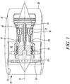
- FIG 2 illustrates a unit mount apparatus 100.
- the unit mount apparatus 100 comprises a unit 102 and a mount 104 for mounting the unit 102 on a gas turbine engine casing, such as inner or outer casing 23, 24 as described in relation to Figure 1 above.
- the unit 102 is a unit for performing some function relating to the operation of a gas turbine engine which must be located on the engine casing. Unit 102 will not be described further, but it should be understood that many types of gas engine units are available and that the unit mount 104 may be bespoke for the particular unit 102 and its eventual location within the engine.
- the mount 104 comprises a unit interface 106 and a structural framework 108.
- the unit interface 106 provides an interface for attachment to the unit 102 and is supported upon the structural framework 108, which can be attached to the gas turbine engine casing.
- the unit interface 106 comprises a box-like structure 110 which defines an internal cavity 112.
- the box-like structure comprises a lower wall 114 (to which the structural framework 108 is attached), side walls 116, and an upper wall 118. These walls 114, 116, 118 define a volume which is the internal cavity 112.
- the upper surface of the upper wall 118 defines an interface surface 120.
- the interface surface 120 is a surface of the mount 104 which is overlaid by the unit 102 when attached to the mount 104.
- the unit 102 can be releasably attached to the mount 104, for example using releasable fixings such as bolts, or permanently attached to the mount 104, for example by welding.
- the fixings are not shown in Figure 2 , but is should be understood that the unit 102 can be fixed to the mount 104 with a variety of different methods.
- a plurality of bosses 122 are provided at the periphery of the interface surface 120 in order to space the unit 102 apart from the interface surface 120.
- the bosses may be omitted and the unit 102 may directly contact the interface surface 120 and, in yet other examples, the upper wall 118 may be omitted entirely, and the unit 102 placed to cover an upper aperture of the unit interface 106.
- the upper wall 118 of the unit interface 106 also comprises a plurality of cooling apertures 124 which provide communication between the internal cavity 112 and the exterior space above the upper wall 118.
- the function of these cooling apertures 124 will be described more fully below.
- the framework comprises a first leg 126 and a second leg 128.
- the legs 126, 128 are connected directly at their upper ends to the unit interface 106 and extend generally downwardly and away from the unit 102.
- the legs 126,128 serve to elevate the unit interface 106, and thus the unit 102, from the casing to which the mount 104 is attached. In some examples, many more legs will be provided, but for ease of understanding, only two legs 126, 128 are illustrated here.
- the mount 104 may have a number of pairs of legs like legs 126, 128. In other examples, the mount 104 may have one leg of the form of leg 126 and a plurality of legs of the form of leg 128.
- Each of the legs 126,128 have at their lower end, an interface flange 129 which permits the lower ends of the legs to be fixed to an engine casing, for example with a bolted connection (not shown).
- FIG. 3A shows a cross section through the first leg 126 along the line A-A, it can be seen that the first leg comprises an annular wall 130 which defines an internal passageway 132 along the length of the leg 126.
- the leg 126 is open at its bottom end, which will be fixed to the engine casing, such that an inlet 134 into the internal passageway 132 is provided.
- the internal passageway 132 of the first leg 126 provides a flow path by which cooling air can travel up the leg 126 from the inlet 134 to the upper end of the leg 126.
- the structural framework 108 further comprises a lateral passageway 136 which extends between the upper ends of the first and second legs 126,128.
- the internal passageway 132 of the first leg 126 is connected in series with the lateral passageway 126 such that cooling air can flow from the first leg 126 to the upper end of the second leg 128.
- the lateral passageway 136 is connected to an internal passageway 138 of the second leg 128.
- FIG. 3B a cross section of the second leg 128 is shown.
- the second leg 128 comprises an annular wall 140. However, unlike the first leg 126, the second leg 128 also comprises a central dividing wall 142. The dividing wall 142 divides the second leg 128 along substantially its entire length into a first passage 138a and a second passage 138b. The first and second passages 138a, b together form the internal passageway 138 of the second leg 128.
- the dividing wall 142 separates the first and second passages 138a, b from the upper end of the leg 128 but does not extend entirely to the lower end of the leg 128. Accordingly, the first and second passages 138a, b are in communication at the lower end of the second leg 128, but are separated along the rest of the length of the leg 128.
- the lateral passageway 136 is connected to the upper end of the first passage 138a. Accordingly, cooling air can flow from the lateral passageway 136 into the upper end of the second leg 128 and then down to the lower end of the second leg 128 in the first passage 138a. As the second passage 138b is connected to the first passage 138a at the lower ends thereof, the cooling airflow can then pass back up the second leg 128 in the second passage 138b.
- the upper end of the second passage 138a is connected to the interior cavity 112 of the unit interface 106 such that cooling air flows from the second passage 138b into the interior cavity 112.
- the first or second passage is a helical passage which extends along of the second leg and the other of the first and second passage is a linear passage which extend back along the leg through the centre of the helical passage (i.e. encircled by the helix).
- Such an arrangement could serve to introduce swirl into the fluid flow at the outlet into interior cavity 112 and so improve diffusion and distribution of cooling air at the unit interface surface 120
- the upper wall 118 of the unit interface 106 comprises a plurality of cooling apertures 124 in the form of an array.
- the cooling air which enters the internal cavity 112 from the second leg 128 may circulate within the internal cavity 112 and is then forced out of the cooling apertures 124 by displacement due to more cooling air entering the internal cavity 112.
- the passageways 132, 136 and 138 of the structural framework 108 together form a cooling conduit for delivering cooling air from an air source to the internal cavity 112 of the unit interface 106 for cooling the unit 102 and the unit interface 106.
- the direction of cooling airflow throughout the mount 104 is generally shown with arrows in Figure 2 .
- the cooling conduit extends in series through both legs 126,128 of the structural framework 108 and can therefore provide a cooling effect to the entire structural framework 108 itself.
- further cooling apertures may be provided either in the structural framework 108, or in the unit interface 106 to direct cooling airflow to other parts of the unit 102 or mount 104.
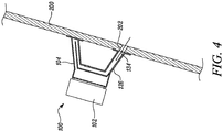
- Figure 4 shows a schematic sectional view of the unit mount apparatus 100 of Figure 1 located on an engine housing 200. Only a small portion of the housing 200 is shown, but it should be understood that the housing 200 could be an inner or outer housing 23, 24 discussed in relation to Figure 1 .
- the interface flanges 129 are located against the surface of the housing 200 and secured in place, for example using bolts or similar.
- the inlet 134 of the first leg 126 is aligned with a port 202 in the housing 200.
- the port 202 provides a source of cooling air into the inlet 134 and therefore to the internal cooling conduit of the mount as discussed above.
- the port 202 may, for example, be a compressor bleed port which provides a flow of relatively cool air from one of the compressors 14, 15 shown in Figure 1 .
- the inlet 134 and the air source may be arranged differently.
- the inlet 134 could instead be provided in the wall 130 of the first leg 126 and the air could be provided by external piping.
- the configuration shown in Figure 4 advantageously provides that the securing of the mount 104 and the connection of the air source to the mount can be conveniently achieved in a single step.
- the cooling enabled by the mount 104 provides temperature control to both the unit 102 and the mount 104 itself. Accordingly, the unit mount assembly 100 described herein may be particularly suitable for use in hotter parts of the gas turbine engine than would be possible with conventional mounts. Accordingly, the mount 104 may enable the unit 102 to be located optimally with less concern for temperature issues and thereby reduce the amount of complex control and other cabling.
- the cooling of the mount 104 may enable lower cost materials to be used in any given situation. In extreme high temperatures, even high-temperature resistant alloys may be unsuitable and a mount 104 may reduce the working temperature within the safe operating range of an existing material. Alternatively, the mount 104 may enable expensive high-temperature resistant alloys to be replaced with cheaper or lighter materials.
- Mounts 104 may also be retro-fitted to existing engines any units to replace conventional mounts. For example, if an engine's performance is increased or altered, then this may increase temperature in the engine, which may necessitate additional cooling. In such a case, a new mount 104 of the same structural shape could be formed, but having an internal cooling conduit to thereby bring the temperature for a unit back into a safe operating range.
- the cooling conduit can be extended through the further legs by providing further lateral passageways and further legs having the same internal construction as the second leg 128.
- a single cooling conduit can extend through every single leg of the structural framework to the unit interface.
- multiple cooling conduits can be formed by various combinations of legs having constructions according to first or second legs 126,128.
- the mount 104 may be constructed as a single contiguous component.
- Additive layer manufacture may be particularly suitable for forming the complex geometries within the structural framework 108, for example.
- a method of manufacturing the mount 104 may comprise producing the unit interface 106, preferably by additive layer manufacture, and producing the structural framework 108 by additive layer manufacture.
- the unit interface 106 and the structural framework 108 may be manufactured separately and subsequently connected, or they may be manufactured together in the same process.
- Additive layer manufacturing may enable the internal cooling conduit and the passageways forming the conduit to be optimised to reduce pressure losses by forming organic or smooth geometries, which may not be possible with conventional manufacturing techniques.
Abstract
Description
- The present disclosure concerns a mount for a gas turbine engine unit.
- In gas turbine engines, many units for various purposes must be attached to the engine and, in particular, to the engine casing. In some cases, units can be attached to the engine casing using a mount. Generally, the unit is attached to the mount, and the mount is attached to the engine casing.
- In some cases, it may not be possible to locate a unit in its optimum position on the casing because the ambient temperature at that would be too great for the unit's safe operation or for the structural integrity of a mount. In such cases, or high-cost, temperature resistant materials may be used, or else the unit must be located elsewhere and an extended network of cabling or control lines must be provided to connect the unit to the necessary components of the engine. These solutions have drawbacks, as they may increase cost, weight, and complexity, and can add further potential failure points into the system.
- Accordingly, it will be understood that improvements are desirable for mounting units to gas turbine engines.
- According to a first aspect there is provided a mount for a gas turbine engine unit comprising: a unit interface for securing a unit to the mount, the unit interface comprising an internal cavity in communication with a cooling aperture to be overlaid by a unit secured to the unit interface; and a structural framework for securing the mount to a gas turbine engine, the structural framework comprising an internal cooling conduit for delivering cooling airflow from an air source to the internal cavity of the unit interface.
- The mount may be for securing a unit to the gas turbine engine, in particular, to an engine casing of a gas turbine engine. The mount may elevate the unit away from the engine casing with the structural framework.
- The unit interface may be a substantially box-like structure having the structural framework extending therefrom, or integrally formed therewith. In other examples, the unit interface and the structural framework may be formed separately and fixed together with a further manufacturing step, such as welding. The unit interface may comprise fixing elements, such as threaded holes or similar for securing a unit to the unit interface. The internal cavity of the unit interface may comprise a substantially open volume within the unit interface, or may comprise one or more conduits extending through the unit interface.
- The structural framework may comprise a plurality of legs. Each of the plurality of legs may have a first end attached to the unit interface and a second end for securing to a gas turbine engine. The legs may be substantially straight, curved, or otherwise. The legs may be interconnected with one or more structural cross-bracing members.
- The cooling conduit may extend through one or more of the plurality of legs. The cooling conduit may extend through all of the plurality of legs. If any structural cross-bracing members are present, the cooling conduit may also extend though the cross bracing members.
- There may be more than one cooling conduit extending through the structural framework. A first internal cooling conduit may extend through a first number of the plurality of legs, and a second internal cooling conduit may extend through a second number of the plurality of legs. A cooling inlet may be provided in the structural framework for receiving cooling air from the air source. The cooling inlet may be provided in a casing interface of one or more of the plurality of legs.
- At least one of the plurality of legs may comprise an internal passageway having an inlet and an outlet. In some examples, both the inlet and outlet may be located at the same end of the leg. In other examples, the inlet and outlet may be located at opposing ends of the leg, or at other positions on the leg, or elsewhere on the mount. The cooling conduit may extend from the air source to the internal cavity via the internal passageway of the leg. For the avoidance of doubt, the cooling conduit may comprise other internal passageways within the legs and other parts of the structural framework arranged in series or in parallel to transport cooling air from the air source to the internal cavity.
- The internal passageways of the leg or legs may comprise a single inlet and single outlet. In some examples, both of the inlet and outlet may be located at the same end of the leg and, in particular, at the first end of the leg proximate the unit interface.
- The internal passageway may extend from the inlet to the outlet along a path which extends along substantially an entire length of the leg. In some examples the internal passageway may be substantially U-shaped having its inlet and outlet at the first end of the leg.
- The internal passageway may comprise a first passage for directing cooling air in a first direction along the leg and a second passage connected in series with the first passage for directing cooling air in a second direction along the leg.
- The first and second passages of the internal passageway may be substantially linear passages which extend in an axial direction along the leg.
- One of the first and second passages may be a helical passage and the other of the first and second passages may be an axial passage which extends in an axial direction along the leg. In some examples, the axial passage may extend within a helix of the helical passage. The axial passage may be circumscribed by the helical passage.
- The mount may further comprise one or more bosses for spacing a unit apart from the cooling aperture.
- The unit interface may comprise an interface surface to be overlaid by a unit. The interface surface may comprise an array of cooling apertures arranged to deliver cooling air from the internal cavity onto a unit secured to the unit interface. The interface surface may be configured to receive a unit directly against or in contact with the interface surface.
- The unit is one or more of an electronic unit, an engine control unit, an engine system control unit, or any other device associated with the control and monitoring of a gas turbine engine.
- In a second aspect, there is provided a unit mount apparatus comprising: a mount according to the first aspect; and a unit secured to the unit interface of the mount.
- In a third aspect, there is provided a gas turbine engine comprising a mount according to the first aspect or a unit mount apparatus according to the second aspect.
- The mount or unit mount apparatus may be attached to an engine casing of the gas turbine engine. The gas turbine engine may be configured to deliver cooling air to an inlet of the internal cooling conduit.
- In a fourth aspect, there is provided a method of manufacturing a mount for a gas turbine engine unit comprising: producing a unit interface of a mount for securing a unit to the mount, the unit interface being configured to deliver cooling air from an internal cavity onto a unit secured to the unit interface; and producing, using additive layer manufacturing, a structural framework of a mount for securing the mount to a gas turbine engine, the structural framework comprising an internal cooling conduit for delivering cooling airflow from an air source to the internal cavity of the unit interface .
- In some examples, the unit interface, or any other part of the mount may also be manufactured using additive layer manufacture.
- The skilled person will appreciate that, except where mutually exclusive, a feature described in relation to any one of the above aspects may be applied mutatis mutandis to any other aspect. Furthermore, except where mutually exclusive, any feature described herein may be applied to any aspect and/or combined with any other feature described herein.
- Embodiments will now be described by way of example only, with reference to the Figures, in which:
-
Figure 1 is a sectional side view of a gas turbine engine; -
Figure 2 is a schematic sectional view of a mount for a gas turbine engine unit; -
Figure 3A is a schematic sectional view of a first leg of the mount along the line A-A inFigure 2 ; -
Figure 3B is a schematic sectional view of a second leg of the mount along the line B-B inFigure 2 ; and -
Figure 4 is a schematic sectional view of the mount ofFigure 2 attached to a gas turbine engine. - With reference to
Figure 1 , a gas turbine engine is generally indicated at 10, having a principal androtational axis 11. Theengine 10 comprises, in axial flow series, anair intake 12, apropulsive fan 13, anintermediate pressure compressor 14, a high-pressure compressor 15,combustion equipment 16, a high-pressure turbine 17, anintermediate pressure turbine 18, a low-pressure turbine 19 and anexhaust nozzle 20. Anacelle 21 generally surrounds theengine 10 and defines both theintake 12 and theexhaust nozzle 20. - The
gas turbine engine 10 works in the conventional manner so that air entering theintake 12 is accelerated by thefan 13 to produce two air flows: a first air flow into theintermediate pressure compressor 14 and a second air flow which passes through abypass duct 22 to provide propulsive thrust. Theintermediate pressure compressor 14 compresses the airflow directed into it before delivering that air to thehigh pressure compressor 15 where further compression takes place. - The compressed air exhausted from the high-
pressure compressor 15 is directed into thecombustion equipment 16 where it is mixed with fuel and the mixture combusted. The resultant hot combustion products then expand through, and thereby drive the high, intermediate and low-pressure turbines nozzle 20 to provide additional propulsive thrust. The high 17, intermediate 18 and low 19 pressure turbines drive respectively thehigh pressure compressor 15,intermediate pressure compressor 14 andfan 13, each by suitable interconnecting shaft. - The
engine 10 comprises an innerannular casing 23 which houses the shaft, compressors, and turbines. An outerannular casing 24 is concentrically arranged about theinner casing 23 and houses thefan 13. The inner andouter casings - Other gas turbine engines to which the present disclosure may be applied may have alternative configurations. By way of example such engines may have an alternative number of interconnecting shafts (e.g. two) and/or an alternative number of compressors and/or turbines. Further the engine may comprise a gearbox provided in the drive train from a turbine to a compressor and/or fan.
-
Figure 2 illustrates aunit mount apparatus 100. Theunit mount apparatus 100 comprises aunit 102 and amount 104 for mounting theunit 102 on a gas turbine engine casing, such as inner orouter casing Figure 1 above. - The
unit 102 is a unit for performing some function relating to the operation of a gas turbine engine which must be located on the engine casing.Unit 102 will not be described further, but it should be understood that many types of gas engine units are available and that theunit mount 104 may be bespoke for theparticular unit 102 and its eventual location within the engine. - The
mount 104 comprises aunit interface 106 and astructural framework 108. Theunit interface 106 provides an interface for attachment to theunit 102 and is supported upon thestructural framework 108, which can be attached to the gas turbine engine casing. - The
unit interface 106 comprises a box-like structure 110 which defines aninternal cavity 112. The box-like structure comprises a lower wall 114 (to which thestructural framework 108 is attached),side walls 116, and anupper wall 118. Thesewalls internal cavity 112. - The upper surface of the
upper wall 118 defines aninterface surface 120. Theinterface surface 120 is a surface of themount 104 which is overlaid by theunit 102 when attached to themount 104. Theunit 102 can be releasably attached to themount 104, for example using releasable fixings such as bolts, or permanently attached to themount 104, for example by welding. The fixings are not shown inFigure 2 , but is should be understood that theunit 102 can be fixed to themount 104 with a variety of different methods. - In this example, a plurality of
bosses 122 are provided at the periphery of theinterface surface 120 in order to space theunit 102 apart from theinterface surface 120. In other examples, the bosses may be omitted and theunit 102 may directly contact theinterface surface 120 and, in yet other examples, theupper wall 118 may be omitted entirely, and theunit 102 placed to cover an upper aperture of theunit interface 106. - The
upper wall 118 of theunit interface 106 also comprises a plurality of coolingapertures 124 which provide communication between theinternal cavity 112 and the exterior space above theupper wall 118. The function of these coolingapertures 124 will be described more fully below. - Turning now to the
structural framework 108, it will be seen that the framework comprises afirst leg 126 and asecond leg 128. Thelegs unit interface 106 and extend generally downwardly and away from theunit 102. The legs 126,128 serve to elevate theunit interface 106, and thus theunit 102, from the casing to which themount 104 is attached. In some examples, many more legs will be provided, but for ease of understanding, only twolegs mount 104 may have a number of pairs of legs likelegs mount 104 may have one leg of the form ofleg 126 and a plurality of legs of the form ofleg 128. - Each of the legs 126,128 have at their lower end, an
interface flange 129 which permits the lower ends of the legs to be fixed to an engine casing, for example with a bolted connection (not shown). - Now referring also to
Figure 3A , which shows a cross section through thefirst leg 126 along the line A-A, it can be seen that the first leg comprises anannular wall 130 which defines aninternal passageway 132 along the length of theleg 126. Theleg 126 is open at its bottom end, which will be fixed to the engine casing, such that aninlet 134 into theinternal passageway 132 is provided. - The
internal passageway 132 of thefirst leg 126 provides a flow path by which cooling air can travel up theleg 126 from theinlet 134 to the upper end of theleg 126. - A shown in
Figure 2 , thestructural framework 108 further comprises alateral passageway 136 which extends between the upper ends of the first and second legs 126,128. Theinternal passageway 132 of thefirst leg 126 is connected in series with thelateral passageway 126 such that cooling air can flow from thefirst leg 126 to the upper end of thesecond leg 128. - At the upper end of the
second leg 128, thelateral passageway 136 is connected to an internal passageway 138 of thesecond leg 128. Referring also toFigure 3B , a cross section of thesecond leg 128 is shown. - The
second leg 128 comprises anannular wall 140. However, unlike thefirst leg 126, thesecond leg 128 also comprises acentral dividing wall 142. The dividingwall 142 divides thesecond leg 128 along substantially its entire length into afirst passage 138a and a second passage 138b. The first andsecond passages 138a, b together form the internal passageway 138 of thesecond leg 128. - As can be seen in
Figure 1 , the dividingwall 142 separates the first andsecond passages 138a, b from the upper end of theleg 128 but does not extend entirely to the lower end of theleg 128. Accordingly, the first andsecond passages 138a, b are in communication at the lower end of thesecond leg 128, but are separated along the rest of the length of theleg 128. - The
lateral passageway 136 is connected to the upper end of thefirst passage 138a. Accordingly, cooling air can flow from thelateral passageway 136 into the upper end of thesecond leg 128 and then down to the lower end of thesecond leg 128 in thefirst passage 138a. As the second passage 138b is connected to thefirst passage 138a at the lower ends thereof, the cooling airflow can then pass back up thesecond leg 128 in the second passage 138b. The upper end of thesecond passage 138a is connected to theinterior cavity 112 of theunit interface 106 such that cooling air flows from the second passage 138b into theinterior cavity 112. - In an alternative configuration, the first or second passage is a helical passage which extends along of the second leg and the other of the first and second passage is a linear passage which extend back along the leg through the centre of the helical passage (i.e. encircled by the helix). Such an arrangement could serve to introduce swirl into the fluid flow at the outlet into
interior cavity 112 and so improve diffusion and distribution of cooling air at theunit interface surface 120 - As discussed above, the
upper wall 118 of theunit interface 106 comprises a plurality of coolingapertures 124 in the form of an array. The cooling air which enters theinternal cavity 112 from thesecond leg 128 may circulate within theinternal cavity 112 and is then forced out of the coolingapertures 124 by displacement due to more cooling air entering theinternal cavity 112. - Thus, the
passageways structural framework 108 together form a cooling conduit for delivering cooling air from an air source to theinternal cavity 112 of theunit interface 106 for cooling theunit 102 and theunit interface 106. The direction of cooling airflow throughout themount 104 is generally shown with arrows inFigure 2 . Furthermore, as the cooling conduit extends in series through both legs 126,128 of thestructural framework 108 and can therefore provide a cooling effect to the entirestructural framework 108 itself. In some examples, further cooling apertures may be provided either in thestructural framework 108, or in theunit interface 106 to direct cooling airflow to other parts of theunit 102 ormount 104. -
Figure 4 shows a schematic sectional view of theunit mount apparatus 100 ofFigure 1 located on anengine housing 200. Only a small portion of thehousing 200 is shown, but it should be understood that thehousing 200 could be an inner orouter housing Figure 1 . - The
interface flanges 129 are located against the surface of thehousing 200 and secured in place, for example using bolts or similar. - When correctly located, the
inlet 134 of thefirst leg 126 is aligned with aport 202 in thehousing 200. Theport 202 provides a source of cooling air into theinlet 134 and therefore to the internal cooling conduit of the mount as discussed above. Theport 202 may, for example, be a compressor bleed port which provides a flow of relatively cool air from one of thecompressors Figure 1 . In other examples, theinlet 134 and the air source may be arranged differently. For example, theinlet 134 could instead be provided in thewall 130 of thefirst leg 126 and the air could be provided by external piping. However, the configuration shown inFigure 4 advantageously provides that the securing of themount 104 and the connection of the air source to the mount can be conveniently achieved in a single step. - The cooling enabled by the
mount 104 provides temperature control to both theunit 102 and themount 104 itself. Accordingly, theunit mount assembly 100 described herein may be particularly suitable for use in hotter parts of the gas turbine engine than would be possible with conventional mounts. Accordingly, themount 104 may enable theunit 102 to be located optimally with less concern for temperature issues and thereby reduce the amount of complex control and other cabling. - Furthermore, the cooling of the
mount 104 may enable lower cost materials to be used in any given situation. In extreme high temperatures, even high-temperature resistant alloys may be unsuitable and amount 104 may reduce the working temperature within the safe operating range of an existing material. Alternatively, themount 104 may enable expensive high-temperature resistant alloys to be replaced with cheaper or lighter materials. -
Mounts 104 may also be retro-fitted to existing engines any units to replace conventional mounts. For example, if an engine's performance is increased or altered, then this may increase temperature in the engine, which may necessitate additional cooling. In such a case, anew mount 104 of the same structural shape could be formed, but having an internal cooling conduit to thereby bring the temperature for a unit back into a safe operating range. - It will be understood that if it is necessary for the
structural framework 108 to have more than two legs, then the cooling conduit can be extended through the further legs by providing further lateral passageways and further legs having the same internal construction as thesecond leg 128. Thus, a single cooling conduit can extend through every single leg of the structural framework to the unit interface. Alternatively, multiple cooling conduits can be formed by various combinations of legs having constructions according to first or second legs 126,128. - In some examples, the
mount 104, or various parts thereof, may be constructed as a single contiguous component. Additive layer manufacture may be particularly suitable for forming the complex geometries within thestructural framework 108, for example. - Accordingly, a method of manufacturing the
mount 104 may comprise producing theunit interface 106, preferably by additive layer manufacture, and producing thestructural framework 108 by additive layer manufacture. Theunit interface 106 and thestructural framework 108 may be manufactured separately and subsequently connected, or they may be manufactured together in the same process. - Additive layer manufacturing may enable the internal cooling conduit and the passageways forming the conduit to be optimised to reduce pressure losses by forming organic or smooth geometries, which may not be possible with conventional manufacturing techniques.
- It will be understood that the invention is not limited to the embodiments above-described and various modifications and improvements can be made without departing from the concepts described herein. Except where mutually exclusive, any of the features may be employed separately or in combination with any other features and the disclosure extends to and includes all combinations and subcombinations of one or more features described herein.
Claims (15)
- A mount (104) for a gas turbine engine unit (102) comprising:a unit interface (106) for securing a unit to the mount (104), the unit interface (106) comprising an internal cavity (112) in communication with a cooling aperture (124) to be overlaid by a unit secured to the unit interface (106); anda structural framework (108) for securing the mount (104) to a gas turbine engine (10), the structural framework comprising an internal cooling conduit (132, 136, 138) for delivering cooling airflow from an air source to the internal cavity (112) of the unit interface (106).
- A mount (104) for a gas turbine engine unit (102) as claimed in claim 1, wherein the structural framework (108) comprises a plurality of legs (126,128), each of the plurality of legs having a first end attached to the unit interface and a second end for securing to a gas turbine engine (10), optionally wherein the cooling conduit (132, 136, 138) extends through one or more of the plurality of legs (126,128),
- A mount (104) for a gas turbine engine unit (102) as claimed in claim 2, wherein:at least one of the plurality of legs (128) comprises an internal passageway (138) having an inlet and an outlet, both the inlet and outlet being located at the same end of the leg (128); andthe cooling conduit extends from the air source to the internal cavity via the internal passageway (138) of the second leg, optionally wherein the internal passageway (138) comprises a single inlet and single outlet both being located at the same end of the leg (128).
- A mount (104) for a gas turbine engine unit (102) as claimed in claim 3, wherein the internal passageway (138) extends from the inlet to the outlet along a path which extends along substantially an entire length of the leg (128).
- A mount (104) for a gas turbine engine unit (102) as claimed in claim 3 or 4, wherein the internal passageway (138) comprises a first passage (138a) for directing cooling air in a first direction along the leg and a second passage (138b) connected in series with the first passage (138a) for directing cooling air in a second direction along the leg (128), optionally wherein the first and second passages (138a,138b) are substantially linear passages which extend in an axial direction along the leg (128), or optionally wherein one of the first and second passages (138a,138b) is a helical passage and the other of the first and second passages is an axial passage which extends in an axial direction along the leg (128), and optionally wherein the axial passage extends within a helix of the helical passage.
- A mount (104) for a gas turbine engine unit (102) as claimed in any preceding claim, wherein the mount (104) further comprises one or more bosses (122) for spacing a unit apart from an interface surface (120) of the unit interface (106).
- A mount (104) for a gas turbine engine unit (102) as claimed in any preceding claim, wherein the unit interface (106) comprises an interface surface (120) to be overlaid by a unit, the interface surface (120) comprising an array of cooling apertures (124) arranged to deliver cooling air from the internal cavity (112) onto a unit secured to the unit interface (106).
- A mount (104) for a gas turbine engine unit (102) as claimed in any preceding claim wherein the unit is one or more of an electronic unit, an engine control unit, or an engine system control unit.
- A unit mount apparatus (100) comprising:a mount (104) according to any of preceding claims; anda unit (102) secured to the unit interface (106) of the mount (104).
- A gas turbine engine (10) comprising a mount (104) according to any one of claims 1-8 or a unit mount apparatus (100) according to claim 9.
- A gas turbine engine (10) as claimed in claim 10, wherein the mount (104) or unit mount apparatus (100) is attached to an engine casing of the gas turbine engine (10).
- A gas turbine engine (10) as claimed in claim 10 or 11, wherein the gas turbine engine (10) is configured to deliver cooling air to an inlet (134) of the internal cooling conduit (132, 136, 138).
- A method of manufacturing a mount (104) for a gas turbine engine unit (102) comprising:producing a unit interface (106) for securing a unit to the mount (104), the unit interface (106) being configured to deliver cooling air from an internal cavity (112) onto a unit secured to the unit interface (106); andproducing, using additive layer manufacturing, a structural framework (108) for securing the mount (104) to a gas turbine engine (10), the structural framework (108) comprising an internal cooling conduit (132, 136, 138) for delivering cooling airflow from an air source to the internal cavity (112) of the unit interface (106).
- A method of manufacturing a mount (104) for a gas turbine engine unit (102) according to claim 13, wherein the step of producing the unit interface comprises the use of additive layer manufacturing.
- A method of manufacturing a mount (104) for a gas turbine engine unit (102) according to claim 14, wherein the unit interface and the structural framework are produced using the same additive layer manufacturing process.
Applications Claiming Priority (1)
| Application Number | Priority Date | Filing Date | Title |
|---|---|---|---|
| GBGB1800778.1A GB201800778D0 (en) | 2018-01-18 | 2018-01-18 | Mount for a gas turbine engine unit |
Publications (1)
| Publication Number | Publication Date |
|---|---|
| EP3514338A1 true EP3514338A1 (en) | 2019-07-24 |
Family
ID=61283739
Family Applications (1)
| Application Number | Title | Priority Date | Filing Date |
|---|---|---|---|
| EP18213288.6A Withdrawn EP3514338A1 (en) | 2018-01-18 | 2018-12-18 | Mount with cooling conduit for a gas turbine engine unit |
Country Status (3)
| Country | Link |
|---|---|
| US (1) | US20190218939A1 (en) |
| EP (1) | EP3514338A1 (en) |
| GB (1) | GB201800778D0 (en) |
Families Citing this family (1)
| Publication number | Priority date | Publication date | Assignee | Title |
|---|---|---|---|---|
| US20200094471A1 (en) * | 2018-09-24 | 2020-03-26 | The Boeing Company | Additively-manufactured component having at least one stiffening member and method of forming the same |
Citations (9)
| Publication number | Priority date | Publication date | Assignee | Title |
|---|---|---|---|---|
| US3864056A (en) * | 1973-07-27 | 1975-02-04 | Westinghouse Electric Corp | Cooled turbine blade ring assembly |
| US4076452A (en) * | 1974-04-09 | 1978-02-28 | Brown, Boveri-Sulzer Turbomaschinen Ag | Gas turbine plant |
| JPH0622529U (en) * | 1992-08-24 | 1994-03-25 | カルソニック株式会社 | Engine oil cooling system |
| JPH11314257A (en) * | 1998-05-01 | 1999-11-16 | Nissei Plastics Ind Co | Hydraulic pressure generation device for injection molding machine |
| US20120195750A1 (en) * | 2011-01-31 | 2012-08-02 | General Electric Company | Turbomachine supports having thermal control system |
| FR2995497A1 (en) * | 2012-09-10 | 2014-03-14 | Airbus Operations Sas | System for cooling e.g. electronic control unit of turbojet of transport aircraft, has heat pipe whose end is connected to heat exchanger elements that are arranged in wall subjected to cooled flow so as to allow heat pipe to restore heat |
| US20170107851A1 (en) * | 2015-07-24 | 2017-04-20 | Pratt & Whitney Canada Corp. | Mid-turbine frame spoke cooling system and method |
| US20170204736A1 (en) * | 2016-01-19 | 2017-07-20 | Rolls-Royce Corporation | Gas turbine engine with health monitoring system |
| EP3266993A1 (en) * | 2016-07-07 | 2018-01-10 | Rolls-Royce plc | A mounting bracket |
-
2018
- 2018-01-18 GB GBGB1800778.1A patent/GB201800778D0/en not_active Ceased
- 2018-12-18 EP EP18213288.6A patent/EP3514338A1/en not_active Withdrawn
- 2018-12-27 US US16/233,683 patent/US20190218939A1/en not_active Abandoned
Patent Citations (9)
| Publication number | Priority date | Publication date | Assignee | Title |
|---|---|---|---|---|
| US3864056A (en) * | 1973-07-27 | 1975-02-04 | Westinghouse Electric Corp | Cooled turbine blade ring assembly |
| US4076452A (en) * | 1974-04-09 | 1978-02-28 | Brown, Boveri-Sulzer Turbomaschinen Ag | Gas turbine plant |
| JPH0622529U (en) * | 1992-08-24 | 1994-03-25 | カルソニック株式会社 | Engine oil cooling system |
| JPH11314257A (en) * | 1998-05-01 | 1999-11-16 | Nissei Plastics Ind Co | Hydraulic pressure generation device for injection molding machine |
| US20120195750A1 (en) * | 2011-01-31 | 2012-08-02 | General Electric Company | Turbomachine supports having thermal control system |
| FR2995497A1 (en) * | 2012-09-10 | 2014-03-14 | Airbus Operations Sas | System for cooling e.g. electronic control unit of turbojet of transport aircraft, has heat pipe whose end is connected to heat exchanger elements that are arranged in wall subjected to cooled flow so as to allow heat pipe to restore heat |
| US20170107851A1 (en) * | 2015-07-24 | 2017-04-20 | Pratt & Whitney Canada Corp. | Mid-turbine frame spoke cooling system and method |
| US20170204736A1 (en) * | 2016-01-19 | 2017-07-20 | Rolls-Royce Corporation | Gas turbine engine with health monitoring system |
| EP3266993A1 (en) * | 2016-07-07 | 2018-01-10 | Rolls-Royce plc | A mounting bracket |
Also Published As
| Publication number | Publication date |
|---|---|
| GB201800778D0 (en) | 2018-03-07 |
| US20190218939A1 (en) | 2019-07-18 |
Similar Documents
| Publication | Publication Date | Title |
|---|---|---|
| CN107013335B (en) | Gas turbine engine and cooling circuit therefor | |
| US7665310B2 (en) | Gas turbine engine having a cooling-air nacelle-cowl duct integral with a nacelle cowl | |
| US8328504B2 (en) | Aeroengine drain assembly | |
| EP2519726B1 (en) | Gas turbine engine and frame | |
| CN109196203B (en) | Fuel delivery system for a gas turbine engine | |
| EP3075964A1 (en) | System for cooling a turbine engine | |
| EP3121418A1 (en) | Cooling system for a turbine engine | |
| JP6283398B2 (en) | Integrated oil tank heat exchanger | |
| US10024193B2 (en) | Pin supported CMC shroud | |
| US10760589B2 (en) | Turbofan engine assembly and methods of assembling the same | |
| US10221773B2 (en) | Bleed valve assembly for a gas turbine engine | |
| US10233845B2 (en) | Bleed valve assembly for a gas turbine engine | |
| US10221712B2 (en) | Seal for hardware segments | |
| US9328629B2 (en) | Outer case with gusseted boss | |
| US11377957B2 (en) | Gas turbine engine with a diffuser cavity cooled compressor | |
| EP3196422B1 (en) | Exhaust frame | |
| EP3514338A1 (en) | Mount with cooling conduit for a gas turbine engine unit | |
| US20200182471A1 (en) | Turbine scroll assembly for gas turbine engine | |
| EP3333375A1 (en) | Sync ring assembly and associated clevis including a rib | |
| US11788469B2 (en) | Thermal management system for a gas turbine engine | |
| US20240084733A1 (en) | Closed-loop cooling system for a gas turbine engine | |
| US10968833B2 (en) | Accessory gearbox for a gas turbine engine | |
| US10202856B2 (en) | Decoupled gas turbine engine |
Legal Events
| Date | Code | Title | Description |
|---|---|---|---|
| PUAI | Public reference made under article 153(3) epc to a published international application that has entered the european phase |
Free format text: ORIGINAL CODE: 0009012 |
|
| AK | Designated contracting states |
Kind code of ref document: A1 Designated state(s): AL AT BE BG CH CY CZ DE DK EE ES FI FR GB GR HR HU IE IS IT LI LT LU LV MC MK MT NL NO PL PT RO RS SE SI SK SM TR |
|
| AX | Request for extension of the european patent |
Extension state: BA ME |
|
| 17P | Request for examination filed |
Effective date: 20190912 |
|
| RBV | Designated contracting states (corrected) |
Designated state(s): AL AT BE BG CH CY CZ DE DK EE ES FI FR GB GR HR HU IE IS IT LI LT LU LV MC MK MT NL NO PL PT RO RS SE SI SK SM TR |
|
| RAP1 | Party data changed (applicant data changed or rights of an application transferred) |
Owner name: ROLLS-ROYCE PLC |
|
| STAA | Information on the status of an ep patent application or granted ep patent |
Free format text: STATUS: THE APPLICATION HAS BEEN WITHDRAWN |
|
| 18W | Application withdrawn |
Effective date: 20200603 |