EP3514099A1 - Vorrichtung zur befestigung eines kran- oder führungsseils an einem rotorblatt einer windenergieanlage - Google Patents
Vorrichtung zur befestigung eines kran- oder führungsseils an einem rotorblatt einer windenergieanlage Download PDFInfo
- Publication number
- EP3514099A1 EP3514099A1 EP19152263.0A EP19152263A EP3514099A1 EP 3514099 A1 EP3514099 A1 EP 3514099A1 EP 19152263 A EP19152263 A EP 19152263A EP 3514099 A1 EP3514099 A1 EP 3514099A1
- Authority
- EP
- European Patent Office
- Prior art keywords
- inlay
- rotor blade
- rotor
- crane
- sheathing element
- Prior art date
- Legal status (The legal status is an assumption and is not a legal conclusion. Google has not performed a legal analysis and makes no representation as to the accuracy of the status listed.)
- Granted
Links
Images

Classifications
-
- F—MECHANICAL ENGINEERING; LIGHTING; HEATING; WEAPONS; BLASTING
- F03—MACHINES OR ENGINES FOR LIQUIDS; WIND, SPRING, OR WEIGHT MOTORS; PRODUCING MECHANICAL POWER OR A REACTIVE PROPULSIVE THRUST, NOT OTHERWISE PROVIDED FOR
- F03D—WIND MOTORS
- F03D13/00—Assembly, mounting or commissioning of wind motors; Arrangements specially adapted for transporting wind motor components
- F03D13/10—Assembly of wind motors; Arrangements for erecting wind motors
-
- B—PERFORMING OPERATIONS; TRANSPORTING
- B66—HOISTING; LIFTING; HAULING
- B66C—CRANES; LOAD-ENGAGING ELEMENTS OR DEVICES FOR CRANES, CAPSTANS, WINCHES, OR TACKLES
- B66C1/00—Load-engaging elements or devices attached to lifting or lowering gear of cranes or adapted for connection therewith for transmitting lifting forces to articles or groups of articles
- B66C1/10—Load-engaging elements or devices attached to lifting or lowering gear of cranes or adapted for connection therewith for transmitting lifting forces to articles or groups of articles by mechanical means
- B66C1/108—Load-engaging elements or devices attached to lifting or lowering gear of cranes or adapted for connection therewith for transmitting lifting forces to articles or groups of articles by mechanical means for lifting parts of wind turbines
-
- F—MECHANICAL ENGINEERING; LIGHTING; HEATING; WEAPONS; BLASTING
- F03—MACHINES OR ENGINES FOR LIQUIDS; WIND, SPRING, OR WEIGHT MOTORS; PRODUCING MECHANICAL POWER OR A REACTIVE PROPULSIVE THRUST, NOT OTHERWISE PROVIDED FOR
- F03D—WIND MOTORS
- F03D1/00—Wind motors with rotation axis substantially parallel to the air flow entering the rotor
- F03D1/06—Rotors
- F03D1/065—Rotors characterised by their construction elements
- F03D1/0658—Arrangements for fixing wind-engaging parts to a hub
-
- F—MECHANICAL ENGINEERING; LIGHTING; HEATING; WEAPONS; BLASTING
- F05—INDEXING SCHEMES RELATING TO ENGINES OR PUMPS IN VARIOUS SUBCLASSES OF CLASSES F01-F04
- F05B—INDEXING SCHEME RELATING TO WIND, SPRING, WEIGHT, INERTIA OR LIKE MOTORS, TO MACHINES OR ENGINES FOR LIQUIDS COVERED BY SUBCLASSES F03B, F03D AND F03G
- F05B2230/00—Manufacture
- F05B2230/60—Assembly methods
- F05B2230/61—Assembly methods using auxiliary equipment for lifting or holding
-
- Y—GENERAL TAGGING OF NEW TECHNOLOGICAL DEVELOPMENTS; GENERAL TAGGING OF CROSS-SECTIONAL TECHNOLOGIES SPANNING OVER SEVERAL SECTIONS OF THE IPC; TECHNICAL SUBJECTS COVERED BY FORMER USPC CROSS-REFERENCE ART COLLECTIONS [XRACs] AND DIGESTS
- Y02—TECHNOLOGIES OR APPLICATIONS FOR MITIGATION OR ADAPTATION AGAINST CLIMATE CHANGE
- Y02E—REDUCTION OF GREENHOUSE GAS [GHG] EMISSIONS, RELATED TO ENERGY GENERATION, TRANSMISSION OR DISTRIBUTION
- Y02E10/00—Energy generation through renewable energy sources
- Y02E10/70—Wind energy
- Y02E10/72—Wind turbines with rotation axis in wind direction
-
- Y—GENERAL TAGGING OF NEW TECHNOLOGICAL DEVELOPMENTS; GENERAL TAGGING OF CROSS-SECTIONAL TECHNOLOGIES SPANNING OVER SEVERAL SECTIONS OF THE IPC; TECHNICAL SUBJECTS COVERED BY FORMER USPC CROSS-REFERENCE ART COLLECTIONS [XRACs] AND DIGESTS
- Y02—TECHNOLOGIES OR APPLICATIONS FOR MITIGATION OR ADAPTATION AGAINST CLIMATE CHANGE
- Y02P—CLIMATE CHANGE MITIGATION TECHNOLOGIES IN THE PRODUCTION OR PROCESSING OF GOODS
- Y02P70/00—Climate change mitigation technologies in the production process for final industrial or consumer products
- Y02P70/50—Manufacturing or production processes characterised by the final manufactured product
Definitions
- the invention relates to a device for fastening a guide cable to a rotor blade, for example during lifting of a rotor of a wind turbine rotor, and to a method for its use.
- Wind turbines are known from the prior art. They usually include a rotor which is rotatably mounted on a nacelle, wherein the nacelle is in turn rotatably mounted on a tower. If necessary, the rotor drives a generator via a rotor shaft and a gear. A wind-induced rotational movement of the rotor can thus be converted into electrical energy, which can then be fed via converters and / or transformers - depending on the type of generator also at least partially directly - in an electrical network.
- the rotor comprises a plurality (usually three), substantially radially extending from the rotor axis rotor blades which are rotatably mounted relative to a rotor hub to adjust the angle of attack of the rotor blades.
- the rotor In the construction of wind turbines - depending on the concept - the rotor is first preassembled on the ground, the rotor blades are connected to the rotor hub to form a rotor before the rotor star lifted as such by means of a crane to the already located on the tower nacelle and there the rotor shaft is connected. Alternatively, it is known to lift the rotor blades individually with a crane to the nacelle and fasten it to an already mounted rotor hub.
- guide ropes preferably attached to the upward-pointing rotor blade tips of the rotor star.
- sheet pockets can be used. These are slipped over the tips of the upward-pointing rotor blades.
- the leaf pockets have a stop element for the guide ropes on.
- a disadvantage of this prior art is that aerodynamic attachments are regularly damaged on the rotor blade when inflating the cushion elements.
- Object of the present invention is to provide an apparatus for securing a crane or guide cable to a rotor blade of a wind turbine, the proper use aerodynamic attachments are not damaged on the rotor blade.
- the invention relates to a device for attaching a crane or guide cable to a rotor blade of a wind turbine comprising an unyielding shroud element for completely enclosing a rotor blade in the profile direction with at least one, inflatable inner inlay for selectively establishing a frictional connection between the shroud element and an enclosed by this A rotor blade, wherein the at least one inlay extends in the circumferential direction of the shroud element, wherein the at least one inlay is finite such that the ends of each inlay are respectively disposed adjacent to the shroud element at a distance adjacent to each other so that they can be used with proper use of the device Arranged sides of an aerodynamic attachment to the rotor blade and so shaped in that, in the inflated state of the inlay, the sheathing element is spaced from the aerodynamic attachment.
- circumferential direction of the sheathing element denotes that direction which, in the state of use of the device, runs perpendicular to the rotor blade axis. In other words, the circumferential direction indicates the direction in which the sheathing element lies around the rotor blade.
- the invention has recognized that damage to aerodynamic add-on parts of a rotor blade can be effectively avoided in cuffs or sheet pockets with inflatable inlays, if the corresponding inlay does not extend beyond the aerodynamic attachment, but rather, as provided according to the invention, the inlay has two ends, which come to rest in use on both sides of the aerodynamic attachment. It has been shown that perpendicular to the rotor blade surface acting on the aerodynamic attachment forces are the main cause of damage to aerodynamic add-on parts, which can be significantly reduced by the said measure or even completely avoided.
- the invention has proven to be particularly advantageous for protecting trailing edge serrations on rotor blades.
- a comb-like structure is provided along the trailing edge, are reduced by the noise emissions of the wind turbine during operation.
- These trailing edge combs are aerodynamic attachments whose teeth can be easily damaged by acting as kink load forces.
- the device according to the invention when used properly, reduces or even completely eliminates those forces that could cause the teeth to crease, the risk of damaging the trailing edge of a rotor blade when using a device is also reduced. This is especially true when the two ends of the inlay rest on one side of the trailing edge comb.
- At least one inlay is finite in each case and the ends of each inlay are respectively arranged adjacent to one another on the covering element such that they are properly used on both sides of the trailing edge of the rotor blade - and thus on both sides there provided Schukantenkamms - are arranged.
- the at least one inlay may be formed by a continuous tube or by a plurality of tube pieces and / or pockets arranged in series. If an inlay is formed by a plurality of hose pieces and / or pockets arranged in series, in addition to the two described ends of an inlay, further interruptions in the installation of the inflated inlay on the rotor blade can be created, in which, for example, further aerodynamic attachments can be arranged. If the inlay is not designed as a continuous tube, it is preferred if the individual pieces of tubing and / or pockets of an inlay are fluid-connected to one another such that they can be inflated together.
- the at least one inlay has a remote-controlled or cable-controlled ventilation valve, via which air can be discharged from an inflated inlay.
- the device can be solved by removing the frictional connection with the rotor blade of this.
- the sheath element may be a sheet pocket or a leaf collar.
- a leaf cuff is an open-sided element which surrounds a rotor blade in the circumferential direction, while a leaf pocket is only open on one side and can be slipped over the tip of a rotor blade. Even if the sheathing element is unyielding, it is preferably at the same time sufficiently flexible to allow it to lay around a rotor blade.
- the sheathing element can be opened optionally transversely to the circumferential direction.
- a simple application of the sheath element to a rotor blade is possible.
- the at least one inlay can then be inflated.
- the opening may preferably extend between the two ends of the at least one inlay and be closed, for example, with a rod, for example a carbon rod, which is guided by eyelets on the covering element to both sides of the opening. By pulling out the rod, the device can be opened.
- a crane or guide rope is wound around the device mounted on a rotor blade.
- a stop element for fastening a crane or guide cable is provided on the sheathing element of the device.
- the stop element may, for example, be designed as an eyelet.
- the device according to the invention is first pulled over the rotor blade for its use, before the at least one inlay is subsequently inflated, until a frictional connection between the rotor blade and the device according to the invention results.
- the device when mounting the device over the rotor blade, the device is positioned and aligned such that the ends of the at least one inlay are already arranged prior to inflation on both sides of the aerodynamic attachment to be protected, so that the aerodynamic attachment by inflating the at least one inlay not is damaged.
- the device according to the invention is particularly suitable for fastening a guide cable to the rotor blades of a rotor star for the purpose of holding during the lifting and mounting of a rotor star on a wind energy plant.
- the use according to the invention therefore preferably comprises the attachment of a corresponding guide cable or tether thereto, for example on a stop element of the device.
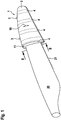
- FIG. 1 schematically a device 1 for attaching a crane or guide rope to a rotor blade 20 of a wind turbine is shown, wherein the device 1 is shown attached for use on a rotor blade 20 with trailing edge comb as an aerodynamic attachment 21.
- the device 1 is designed as a sheet pocket for pushing onto the blade tip of the rotor blade and comprises a substantially unyielding flexible sheathing element 2, for example.
- Truck tarpaulin which is formed as a sheet pocket and on its outside eyelets as stop elements 3 for attachment of crane or Guide cables (not shown).
- On the inside of the sheath element 2 are - as in FIG. 1 indicated by the dashed lines - four inflatable inlays 4 are provided, which extend in the circumferential direction 90 of the sheathing element 2.
- the inlays 4 are all configured comparably, which is why the inlays 4 are shown below by way of example on the in FIG. 2 visible inlay are explained.
- Each of the inlays 4 comprises a finite tube 5 extending in the circumferential direction 90 of the sheath element 2, the two ends 6, 7 of the inlay 4 being arranged at the sheathing element 2 at a distance such that they are in contact with the device 1 as used in US Pat FIGS. 1 and 2 is shown - come to rest on both sides of the aerodynamic attachment 21 on the rotor blade 20. How out FIG. 2 directly visible, the tube 5 is then located on both sides of the trailing edge of the rotor blade 20 and thus also the aerodynamic attachment 21, but without extending over it.
- the tips of the aerodynamic attachment 21 - ie the tips of the teeth of the trailing edge comb - are so free both of the inlay 4 and of the sheathing element 2, that no direct buckling load on the aerodynamic attachment 21 can act. Even if a force is introduced into the device 1 via the eyelet 3, the aerodynamic attachment 21 therefore remains free of damage.
- FIG. 3 is an alternative embodiment of an inlay 4 to that of FIG. 2 shown.
- the inlay 4 continues to extend in the circumferential direction 90 of the sheathing element 2, it is no longer as a continuous tube 5 (see. FIG. 2 But rather as a juxtaposition of a plurality of tube segments 5 'is formed, which are fluidly interconnected by corresponding compounds 8 in the region of the sheath element 2.
- the respective tube segments 5 ' are shaped such that they span the aerodynamic attachment 21 like a bridge, without, however, coming into contact with the tip of the aerodynamic attachment 21.
- the sheath element 2 is in the in FIG. 3 illustrated embodiment openable.
- an opening extending transversely to the circumferential direction 90 is provided between the respective two ends of the inlays 4, to the two sides of which eyelets 9 are alternately arranged.
- a rod 10 is threaded into the eyelets 9; to reopen this rod 10 can be easily pulled out again.
- a vent valve 11 is provided, on which a pull cable for selectively opening the vent valve 11 can be attached.
- a device 1 For the use of a device 1, as in FIGS. 1 to 3 , this is first mounted on non-inflated inlays 4 on the rotor blade 20. Care is taken to ensure that the ends 6, 7 of the inlays 4 already come to rest on both sides of the trailing edge of the rotor blade 20 or of the aerodynamic attachment 21 provided there. Subsequently, the inlays 4 are inflated until a frictional connection between the device 1 and rotor blade 20 results (this state is in FIGS. 1 to 3 shown). After fastening, for example, a guide cable to the eyelets 3, the device can be 1 for example, serve to guide and hold a rotor during lifting and mounting on a wind turbine.
- the air is discharged from the inlays 4 via a cable attached to the vent valve 11, whereby the adhesion to the rotor blade 20 is canceled.
- the device 1 can then be easily removed from the rotor blade 20.
- a possibly provided opening of the sheathing element 2 can additionally be opened.
Landscapes
- Engineering & Computer Science (AREA)
- Mechanical Engineering (AREA)
- Life Sciences & Earth Sciences (AREA)
- Sustainable Development (AREA)
- Sustainable Energy (AREA)
- Chemical & Material Sciences (AREA)
- Combustion & Propulsion (AREA)
- General Engineering & Computer Science (AREA)
- Wind Motors (AREA)
Abstract
Description
- Die Erfindung betrifft eine Vorrichtung zum Befestigen eines Führungsseils an einem Rotorblatt, bspw. während des Anhebens eines Rotorsterns einer Windenergieanlage, sowie ein Verfahren zu deren Verwendung.
- Windenergieanlagen sind aus dem Stand der Technik bekannt. Sie umfassen in der Regel einen Rotor, der drehbar an einer Gondel angeordnet ist, wobei die Gondel wiederum drehbar auf einem Turm angeordnet ist. Der Rotor treibt ggf. über eine Rotorwelle und ein Getriebe einen Generator an. Eine durch Wind induzierte Rotationsbewegung des Rotors kann so in elektrische Energie gewandelt werden, die dann über Umrichter und/oder Transformatoren - je nach Bauart des Generators auch wenigstens teilweise direkt - in ein elektrisches Netz eingespeist werden kann. Der Rotor umfasst mehrere (in der Regel drei), sich im Wesentlichen radial von der Rotorachse erstreckende Rotorblätter, die gegenüber einer Rotornabe drehbar befestigt sind, um den Anstellwinkel der Rotorblätter einzustellen.
- Bei der Errichtung von Windenergieanlagen wird - je nach Konzept - der Rotor zunächst am Boden vormontiert, wobei die Rotorblätter mit der Rotornabe zur Bildung eines Rotorsterns verbunden werden, bevor der Rotorstern als solches mithilfe eines Krans zur bereits auf dem Turm befindlichen Gondel gehoben und dort an die Rotorwelle angebunden wird. Alternativ ist es bekannt, die Rotorblätter einzeln mit einem Kran zur Gondel zu heben und dort an einer bereits montierten Rotornabe zu befestigen.
- Beim Anheben eines vormontierten Rotorsterns zur Gondel über einen Hauptkran ist es erforderlich, das bei der letztendlichen Montage des Rotorsterns an der Gondel nach unten weisende Rotorblatt während des Anhebens aus der horizontalen Lage mit einem Hilfskran mit anzuheben und zu halten, damit dieses Rotorblatt beim Kippen des Rotorstern aus der Horizontalen in eine Vertikale nicht durch Bodenkontakt beschädigt wird. Die Verwendung eines Hilfskrans beim Anheben eines Rotorsterns ist bspw. in
Figur 3 des DokumentesUS 8,595,931 B illustriert. - Außerdem werden, um den Rotorstern während des Anhebens in die gewünschte Montageposition drehen zu können, zusätzlich Führungsseile, bevorzugt an den nach oben zeigenden Rotorblattspitzen des Rotorsterns, befestigt. Zur Befestigung entsprechender Führungsseile am Rotorstern können sogenannte Blatttaschen verwendet werden. Diese werden über die Spitzen der nach oben zeigenden Rotorblätter gestülpt. Die Blatttaschen weisen ein Anschlagelement für die Führungsseile auf. Eine mögliche Ausführung einer solchen Blatttasche ist in
EP 2 562 418 A1 gezeigt. - Beim Anheben eines einzelnen Rotorblatts muss regelmäßig ein Kran- und/oder Führungsseilseil abseits der Blattwurzel am Rotorblatt selbst angreifen.
- Unabhängig von dem letztendlichen Montagekonzept ist es demnach erforderlich, Kran- und/oder Führungsseile an verschiedenen Positionen entlang eines Rotorblatts befestigen zu können. Für eine entsprechende Befestigung sind im Stand der Technik verschiedene Vorrichtungen bekannt. So ist bspw. in Dokument
WO 2013/091655 A1 eine Vorrichtung zur Befestigung eines Kranseils an einem Rotorblatt gezeigt, die wie eine Manschette vollständig um ein Rotorblatt geschlungen wird. Auf der Innenseite der Manschette sind aufblasbare Polsterelemente vorgesehen, mit denen sich wahlweise eine kraftschlüssige Verbindung zwischen Manschette und Rotorblatt herstellen lässt. - Nachteilig an diesem Stand der Technik ist, dass aerodynamische Anbauteile am Rotorblatt beim Aufblasen der Polsterelemente regelmäßig beschädigt werden.
- Aufgabe der vorliegenden Erfindung ist es, eine Vorrichtung zum Befestigen eines Kran- oder Führungsseils an einem Rotorblatt einer Windenergieanlage zu schaffen, bei deren ordnungsgemäßer Verwendung aerodynamische Anbauteile am Rotorblatt nicht beschädigt werden.
- Gelöst wird diese Aufgabe durch die Vorrichtung gemäß dem Hauptanspruch sowie deren Verwendung gemäß dem Anspruch 8. Vorteilhafte Weiterbildungen sind Gegenstand der abhängigen Ansprüche.
- Demnach betrifft die Erfindung eine Vorrichtung zum Befestigen eines Kran- oder Führungsseils an einem Rotorblatt einer Windenergieanlage umfassend ein unnachgiebiges Ummantelungselement zum vollständigen Umschließen eines Rotorblatts in Profilrichtung mit wenigstens einem, innen liegenden aufblasbaren Inlay zum wahlweisen Herstellen einer kraftschlüssigen Verbindung zwischen Ummantelungselement und einem von diesem umschlossenen Rotorblatt, wobei sich das wenigstens eine Inlay in Umfangsrichtung des Ummantelungselementes erstreckt, wobei das wenigstens eine Inlay derart endlich ist, dass die Enden jedes Inlays jeweils so an dem Ummantelungselement mit einem Abstand benachbart zueinander angeordnet sind, dass sie bei ordnungsgemäßer Verwendung der Vorrichtung zu beiden Seiten eines aerodynamischen Anbauteils am Rotorblatt angeordnet und so ausgeformt sind, dass im aufgeblasenen Zustand des Inlays das Ummantelungselement vom aerodynamischen Anbauteil beabstandet ist.
- Weiterhin betrifft die Erfindung eine Verwendung der erfindungsgemäßen Vorrichtung mit den Schritten:
- Aufziehen der Vorrichtung auf ein Rotorblatt, sodass die beiden Enden des wenigstens einen Inlays zu beiden Seiten eines aerodynamischen Anbauteils am Rotorblatt angeordnet sind; und
- Aufblasen des wenigstens einen Inlays zur Herstellung einer kraftschlüssigen Verbindung zwischen Ummantelungselement und Rotorblatt.
- Mit "Umfangsrichtung des Ummantelungselementes" ist in Zusammenhang mit der vorliegenden Erfindung diejenige Richtung bezeichnet, die im Verwendungszustand der Vorrichtung senkrecht zur Rotorblattachse verläuft. In anderen Worten bezeichnet die Umfangsrichtung die Richtung, in der sich das Ummantelungselement um das Rotorblatt legt.
- Die Erfindung hat erkannt, dass Beschädigungen an aerodynamischen Anbauteilen eines Rotorblatts bei Manschetten oder Blatttaschen mit aufblasbaren Inlays wirksam vermieden werden kann, wenn sich das entsprechende Inlay nicht über das aerodynamische Anbauteil hinweg erstreckt, sondern vielmehr, wie erfindungsgemäß vorgesehen, das Inlay zwei Enden aufweist, die bei der Verwendung jeweils zu beiden Seiten des aerodynamischen Anbauteils zu liegen kommen. Es hat sich nämlich gezeigt, dass senkrecht zur Rotorblattoberfläche auf das aerodynamische Anbauteil einwirkende Kräfte die Hauptursache für Beschädigungen an aerodynamischen Anbauteilen sind, die sich durch die genannte Maßnahme deutlich reduzieren oder sogar vollständig vermeiden lassen. Wenn die fraglichen Enden des Inlays mit dem aerodynamischen Anbauteil in Berührung kommen bzw. an diesem Anliegen, werden durch die Trennung des Inlays über das aerodynamische Anbauteil zumindest senkrecht zur Rotorblattoberfläche auf das aerodynamische Anbauteil einwirkende Kräfte deutlich reduziert; wenn die genannten Enden entfernt von dem aerodynamischen Anbauteil angeordnet sind, können diese sogar vollständig vermieden werden.
- Selbstverständlich ist es in beiden Fällen erforderlich, dass das Ummantelungselement selbst ebenfalls nicht mit dem aerodynamischen Anbauteil in Berührung kommt. Das lässt sich aber durch geeignete Ausgestaltung der Enden des Inlays sicherstellen, bspw. indem die Enden das aerodynamische Anbauteil ausreichend weit überragen oder dieses brückenförmig überspannen.
- Die Erfindung hat sich als besonders vorteilhaft zum Schutz von Hinterkantenkämmen ("trailing edge serrations") an Rotorblättern erwiesen. Bei entsprechend ausgestatteten Rotorblättern ist entlang der Hinterkante eine kammartige Struktur vorgesehen, durch die Schallemissionen der Windenergieanlage im Betrieb reduziert werden. Bei diesen Hinterkantenkämmen handelt es sich um aerodynamische Anbauteile, deren Zähne durch darauf als Knicklast einwirkende Kräfte leicht beschädigt werden können. Indem durch die erfindungsgemäße Vorrichtung bei ordnungsgemäßer Verwendung diejenigen Kräfte, die ein Abknicken der Zähne verursachen könnten, reduziert oder gar vollständig vermieden werden, ist auch das Risiko der Beschädigung des Hinterkantenkamms eines Rotorblatts bei der Verwendung einer Vorrichtung reduziert. Dies gilt insbesondere auch dann, wenn die beiden Enden des Inlays an jeweils einer Seite des Hinterkantenkamms anliegen. Für diesen Anwendungsfall ist daher bevorzugt, wenn wenigstens ein Inlay jeweils endlich ist und die Enden jedes Inlays jeweils so an dem Ummantelungselement benachbart zueinander angeordnet sind, dass sie bei ordnungsgemäßer Verwendung der Vorrichtung zu beiden Seiten der Hinterkante des Rotorblatts - und somit zu beiden Seiten eines dort vorgesehenen Hinterkantenkamms - angeordnet sind.
- Das wenigstens eine Inlay kann durch einen durchgehenden Schlauch oder durch mehrere in Reihe angeordnete Schlauchstücke und/oder Taschen gebildet sein. Ist ein Inlay durch mehrere in Reihe angeordnete Schlauchstücke und/oder Taschen gebildet, können neben den beiden beschriebenen Enden eines Inlays noch weitere Unterbrechungen in der Anlage des aufgeblasenen Inlays am Rotorblatt geschaffen werden, in denen bspw. weitere aerodynamische Anbauteile angeordnet sein können. Ist das Inlay nicht als durchgehender Schlauch ausgestaltet, ist es bevorzugt, wenn die einzelnen Schlauchstücke und/oder Taschen eines Inlays untereinander derart fluidverbunden sind, dass sie sich gemeinsam aufblasen lassen.
- Es ist weiter bevorzugt, wenn das wenigstens eine Inlay ein fern- oder seilzuggesteuertes Entlüftungsventil aufweist, über welches Luft aus einem aufgeblasenen Inlay abgelassen werden kann. Dadurch lässt sich die Vorrichtung durch Aufheben der kraftschlüssigen Verbindung mit dem Rotorblatt von diesem lösen. Insbesondere ist es so möglich, eine erfindungsgemäße Vorrichtung nach erfolgter Montage des Rotorblatts bzw. eines Rotorsterns einfach zu lösen.
- Bei dem Ummantelungselement kann es sich um eine Blatttasche oder um eine Blattmanschette handeln. Bei einer Blattmanschette handelt es sich um ein beidseitig offenes, ein Rotorblatt in Umfangsrichtung umschlingendes Element, während eine Blatttasche nur einseitig offen ist und über die Spitze eines Rotorblatts gestülpt werden kann. Auch wenn das Ummantelungselement unnachgiebig ist, ist es vorzugsweise gleichzeitig ausreichend flexibel, um sich um ein Rotorblatt legen zu lassen.
- Es ist bevorzugt, wenn das Ummantelungselement quer zur Umfangsrichtung wahlweise öffenbar ist. Durch eine entsprechende Öffnungsmöglichkeit ist ein einfaches Anlegen des Ummantelungselements um ein Rotorblatt möglich. Nach dem Schließen des Ummantelungselements kann dann das wenigstens eine Inlay aufgeblasen werden. Die Öffnung kann vorzugsweise zwischen den beiden Enden des wenigstens einen Inlays verlaufen und bspw. mit einem Stab, bspw. einem Carbonstab, der durch Ösen an dem Ummantelungselement zu beiden Seiten der Öffnung geführt ist, geschlossen sein. Durch Herausziehen des Stabs kann die Vorrichtung geöffnet werden.
- Grundsätzlich ist es möglich, dass ein Kran- oder Führungsseil um die an einem Rotorblatt montierte Vorrichtung geschlungen wird. Es ist aber bevorzugt, wenn an dem Ummantelungselement der Vorrichtung ein Anschlagelement zur Befestigung eines Kran- oder Führungsseils vorgesehen ist. Das Anschlagelement kann bspw. als Öse ausgestaltet sein.
- Zur Erläuterung des erfindungsgemäßen Verfahrens wird grundsätzlich auf die vorstehenden Ausführungen verwiesen. Die erfindungsgemäße Vorrichtung wird zu ihrer Verwendung zunächst über das Rotorblatt gezogen, bevor anschließend das wenigstens eine Inlay aufgeblasen wird, bis sich eine kraftschlüssige Verbindung zwischen Rotorblatt und erfindungsgemäßer Vorrichtung ergibt. Dabei wird beim Aufziehen der Vorrichtung über das Rotorblatt die Vorrichtung so positioniert und ausgerichtet, dass die Enden des wenigstens einen Inlays bereits vor dem Aufblasen zu beiden Seiten des zu schützenden aerodynamischen Anbauteils angeordnet sind, sodass das aerodynamische Anbauteil durch das Aufblasen des wenigstens einen Inlays nicht beschädigt wird.
- Die erfindungsgemäße Vorrichtung eignet sich insbesondere zur Befestigung eines Führungsseils an den Rotorblättern eines Rotorsterns zum Beihalten während des Anhebens und der Montage eines Rotorsterns an einer Windenergieanlage. Die erfindungsgemäße Verwendung umfasst daher vorzugsweise die Befestigung eines entsprechenden Führungsseils oder Halteseils daran, bspw. an einem Anschlagelement der Vorrichtung.
- Die Erfindung wird nun anhand einer vorteilhaften Ausführungsform unter Bezugnahme auf die beigefügten Zeichnungen beispielhaft beschrieben. Es zeigen:
-
Figur 1 : eine schematische Darstellung eines ersten Ausführungsbeispiels einer erfindungsgemäßen Vorrichtung im Verwendungszustand; -
Figur 2 : eine Schnittansicht durch die Vorrichtung gemäßFigur 1 entlang der Schnittlinie II-II; und -
Figur 3 : eine Schnittansicht durch eine Ausführungsvariante zurFigur 2 . - In
Figur 1 ist schematisch eine Vorrichtung 1 zum Befestigen eines Kran- oder Führungsseils an einem Rotorblatt 20 einer Windenergieanlage dargestellt, wobei die Vorrichtung 1 zur Verwendung an einem Rotorblatt 20 mit Hinterkantenkamm als aerodynamischem Anbauteil 21 angebracht dargestellt ist. - Die Vorrichtung 1 ist als Blatttasche zum Aufschieben auf die Blattspitze des Rotorblatts ausgebildet und umfasst ein im Wesentlichen unnachgiebiges flexibles Ummantelungselement 2, bspw. aus LKW-Plane, welches als Blatttasche ausgeformt ist und an seiner Außenseite Ösen als Anschlagelemente 3 zur Befestigung von Kran- oder Führungsseilen (nicht dargestellt) aufweist. Auf der Innenseite des Ummantelungselementes 2 sind - wie in
Figur 1 durch die gestrichelten Linien angedeutet - vier aufblasbare Inlays 4 vorgesehen, die sich in Umfangsrichtung 90 des Ummantelungselementes 2 erstrecken. - Die Inlays 4 sind alle vergleichbar ausgestaltet, weshalb die Inlays 4 nachfolgend exemplarisch an dem in
Figur 2 sichtbaren Inlay erläutert werden. - Jedes der Inlays 4 umfasst einen endlichen, in Umfangsrichtung 90 des Ummantelungselementes 2 verlaufenden Schlauch 5, wobei die beiden Enden 6, 7 des Inlays 4 so beabstandet an dem Ummantelungselement 2 angeordnet sind, dass diese bei der Verwendung der Vorrichtung 1 - wie sie in
Figuren 1 und2 dargestellt ist - zu beiden Seiten des aerodynamischen Anbauteils 21 am Rotorblatt 20 zu liegen kommen. Wie ausFigur 2 unmittelbar ersichtlich, liegt der Schlauch 5 dann zu beiden Seiten der Hinterkante des Rotorblatts 20 und somit auch des aerodynamischen Anbauteil 21, ohne sich jedoch darüber hinweg zu erstrecken. Dabei liegt der Schlauch zwar seitlich unmittelbar an dem aerodynamischen Anbauteil 21 an, die Spitzen des aerodynamischen Anbauteils 21 - also die Spitzen der Zähne des Hinterkantenkamms - sind hingegen derart frei sowohl von dem Inlay 4 als auch von dem Ummantelungselement 2, dass keine unmittelbare Knickbelastung auf das aerodynamische Anbauteil 21 einwirken kann. Selbst wenn über die Öse 3 eine Kraft in die Vorrichtung 1 eingebracht wird, bleibt das aerodynamische Anbauteil 21 daher beschädigungsfrei. - In
Figur 3 ist eine alternative Ausführungsvariante eines Inlays 4 zu derjenigen ausFigur 2 gezeigt. - Auch wenn sich bei der Ausführungsvariante gemäß
Figur 3 das Inlay 4 weiterhin in Umfangsrichtung 90 des Ummantelungselementes 2 erstreckt, ist es nicht mehr als durchgehender Schlauch 5 (vgl.Figur 2 ) sondern vielmehr als eine Aneinanderreihung von mehreren Schlauchsegmenten 5' ausgebildet, die durch entsprechende Verbindungen 8 im Bereich des Ummantelungselementes 2 untereinander fluidverbunden sind. - Im Bereich der Enden 6, 7 des Inlays 4 sind die jeweiligen Schlauchsegmente 5' derart ausgeformt, dass sie das aerodynamische Anbauteil 21 brückenartig überspannen, ohne dabei jedoch mit der Spitze des aerodynamischen Anbauteils 21 in Verbindung zu kommen. Indem die beiden Enden 6, 7 im dargestellten aufgeblasenen Zustand aneinanderstoßen, kann weiterhin wirksam vermieden werden, dass das Ummantelungselement 2 mit dem aerodynamischen Anbauteil 21 in Kontakt kommt.
- Das Ummantelungselement 2 ist in der in
Figur 3 dargestellten Ausführungsvariante öffenbar. Dazu ist zwischen den jeweils beiden Enden der Inlays 4 eine sich quer zu Umfangrichtung 90 erstreckende Öffnung vorgesehen, zu deren beiden Seiten abwechselnd Ösen 9 angeordnet sind. Zum Verschließen der Öffnung wird ein Stab 10 in die Ösen 9 eingefädelt; zum erneuten Öffnen kann dieser Stab 10 einfach wieder herausgezogen werden. - In sämtlichen hier vorgestellten Ausführungsvarianten ist ein Entlüftungsventil 11 vorgesehen, an dem ein Zugseil zum wahlweisen Öffnen des Entlüftungsventils 11 angebracht werden kann.
- Für die Verwendung einer Vorrichtung 1, wie sie in
Figuren 1 bis 3 , dargestellt ist, wird diese zunächst bei nicht aufgeblasenen Inlays 4 auf das Rotorblatt 20 aufgezogen. Dabei wird darauf geachtet, dass die Enden 6, 7 der Inlays 4 bereits zu beiden Seiten der Hinterkante des Rotorblatts 20 bzw. des dort vorgesehenen aerodynamischen Anbauteils 21 zu liegen kommen. Anschließend werden die Inlays 4 aufgeblasen, bis sich eine kraftschlüssige Verbindung zwischen Vorrichtung 1 und Rotorblatt 20 ergibt (dieser Zustand ist inFiguren 1 bis 3 gezeigt). Nach Befestigung bspw. eines Führungsseils an den Ösen 3 kann die Vorrichtung 1 bspw. dem Führen und Beihalten eines Rotorsterns während des Anhebens und der Montage an einer Windenergieanlage dienen. Nach erfolgter Montage des Rotorsterns, zu dem das Rotorblatt 20 gehört, wird über einen am Entlüftungsventil 11 angebrachten Seilzug die Luft aus den Inlays 4 abgelassen, womit auch der Kraftschluss mit dem Rotorblatt 20 aufgehoben wird. Die Vorrichtung 1 kann dann einfach von dem Rotorblatt 20 abgezogen werden. Dabei kann bei entsprechender Ausgestaltung der Vorrichtung 1 zusätzlich auch eine evtl. vorgesehene Öffnung des Ummantelungselementes 2 geöffnet werden.
Claims (9)
- Vorrichtung (1) zum Befestigen eines Kran- oder Führungsseils an einem Rotorblatt (20) einer Windenergieanlage umfassend ein unnachgiebiges Ummantelungselement (2) zum vollständigen Umschließen eines Rotorblatts (20) in Profilrichtung mit wenigstens einem, innen liegenden aufblasbaren Inlay (4) zum wahlweisen Herstellen einer kraftschlüssigen Verbindung zwischen Ummantelungselement (2) und einem von diesem umschlossenen Rotorblatt (20), wobei sich das wenigstens eine Inlay (4) in Umfangsrichtung (90) des Ummantelungselementes (2) erstreckt,
dadurch gekennzeichnet, dass
das wenigstens eine Inlay (4) derart endlich ist, dass die Enden (5, 6) jedes Inlays (4) jeweils so an dem Ummantelungselement (2) mit einem Abstand benachbart zueinander angeordnet sind, dass sie bei ordnungsgemäßer Verwendung der Vorrichtung (1) zu beiden Seiten eines aerodynamischen Anbauteils (21) am Rotorblatt (20) angeordnet und so ausgeformt sind, dass im aufgeblasenen Zustand des Inlays (4) das Ummantelungselement (2) vom aerodynamischen Anbauteil (21) beabstandet ist. - Vorrichtung nach Anspruch 1,
dadurch gekennzeichnet, dass
die Enden (5, 6) jedes Inlays (4) jeweils so an dem Ummantelungselement (2) benachbart zueinander angeordnet sind, dass sie bei ordnungsgemäßer Verwendung der Vorrichtung (1) zu beiden Seiten der Hinterkante des Rotorblatts (20) angeordnet sind. - Vorrichtung nach einem der vorhergehenden Ansprüche,
dadurch gekennzeichnet, dass
das wenigstens eine Inlay durch einen durchgehenden Schlauch (5) oder durch mehrere in Reihe angeordnete Schlauchstücke (5') und/oder Taschen gebildet ist, wobei die Schlauchstücke (5') und/oder Taschen eines Inlays (4) vorzugsweise untereinander fluidverbunden sind. - Vorrichtung nach einem der vorhergehenden Ansprüche,
dadurch gekennzeichnet, dass
das wenigstens eine Inlay (4) ein fern- oder seilzuggesteuertes Entlüftungsventil (11) aufweist. - Vorrichtung nach einem der vorhergehenden Ansprüche,
dadurch gekennzeichnet, dass
das Ummantelungselement (2) eine Blatttasche oder eine Blattmanschette ist. - Vorrichtung nach einem der vorhergehenden Ansprüche,
dadurch gekennzeichnet, dass
das Ummantelungselement (2) quer zur Umfangsrichtung (90) wahlweise öffenbar ist. - Vorrichtung nach einem der vorhergehenden Ansprüche,
dadurch gekennzeichnet, dass
ein Anschlagelement (3) zur Befestigung eines Kran- oder Führungsseils an dem Ummantelungselement (2) vorgesehen ist. - Verwendung einer Vorrichtung (1) gemäß einem der vorhergehenden Ansprüche, mit den Schritten:- Aufziehen der Vorrichtung (1) auf ein Rotorblatt (20), sodass die beiden Enden (6, 8) des wenigstens einen Inlays (4) zu beiden Seiten eines aerodynamischen Anbauteils (21) am Rotorblatt (20) angeordnet sind; und- Aufblasen des wenigstens einen Inlays (4) zur Herstellung einer kraftschlüssigen Verbindung zwischen Ummantelungselement (2) und Rotorblatt (20).
- Verwendung nach Anspruchs 8,
dadurch gekennzeichnet, dass
nach erfolgter Montage der Vorrichtung (1) am Rotorblatt (20) ein Führungsseil zum Beihalten während des Anhebens und der Montage eines Rotorsterns an einer Windenergieanlage an der Vorrichtung (1) befestigt wird.
Applications Claiming Priority (1)
| Application Number | Priority Date | Filing Date | Title |
|---|---|---|---|
| DE102018000372.9A DE102018000372A1 (de) | 2018-01-18 | 2018-01-18 | Vorrichtung zur Befestigung eines Kran- oder Führungsseils an einem Rotorblatt einerWindenergieanlage |
Publications (2)
| Publication Number | Publication Date |
|---|---|
| EP3514099A1 true EP3514099A1 (de) | 2019-07-24 |
| EP3514099B1 EP3514099B1 (de) | 2022-07-20 |
Family
ID=65036654
Family Applications (1)
| Application Number | Title | Priority Date | Filing Date |
|---|---|---|---|
| EP19152263.0A Active EP3514099B1 (de) | 2018-01-18 | 2019-01-17 | Vorrichtung zur befestigung eines kran- oder führungsseils an einem rotorblatt einer windenergieanlage |
Country Status (2)
| Country | Link |
|---|---|
| EP (1) | EP3514099B1 (de) |
| DE (1) | DE102018000372A1 (de) |
Cited By (3)
| Publication number | Priority date | Publication date | Assignee | Title |
|---|---|---|---|---|
| EP4027011A1 (de) * | 2021-01-10 | 2022-07-13 | General Electric Renovables España S.L. | Verminderung von schwingungen in windturbinen |
| CN116085203A (zh) * | 2023-01-06 | 2023-05-09 | 西北水利水电工程有限责任公司 | 一种风电场风机拆除用风叶限位装置及其限位方法 |
| US20240263610A1 (en) * | 2021-07-23 | 2024-08-08 | Lm Wind Power A/S | Devices and methods for mitigating vibrations in wind turbine blades |
Families Citing this family (1)
| Publication number | Priority date | Publication date | Assignee | Title |
|---|---|---|---|---|
| EP4227525A1 (de) * | 2022-02-15 | 2023-08-16 | Nordex Energy SE & Co. KG | System zum heben einer rotorschaufel einer windturbine |
Citations (4)
| Publication number | Priority date | Publication date | Assignee | Title |
|---|---|---|---|---|
| DE29819391U1 (de) * | 1998-09-22 | 1999-02-11 | Robl, Klaus A., 59505 Bad Sassendorf | Vorrichtung zur Durchführung von Reparatur- und Serviceleistungen insbesondere an Rotorblättern von Windkraftanlagen |
| US20100126897A1 (en) * | 2002-06-06 | 2010-05-27 | Aloys Wobben | Apparatus and methods for handling rotor blades |
| US20120112481A1 (en) * | 2011-12-20 | 2012-05-10 | Ten Thoren Rolf Reinfried | Handling assembly for a wind turbine blade |
| EP3312417A1 (de) * | 2016-10-24 | 2018-04-25 | Gamesa Innovation & Technology, S.L. | Windturbinenschaufelhubvorrichtung und zugehöriges verfahren |
Family Cites Families (7)
| Publication number | Priority date | Publication date | Assignee | Title |
|---|---|---|---|---|
| KR101285921B1 (ko) | 2010-05-31 | 2013-07-12 | 미츠비시 쥬고교 가부시키가이샤 | 풍차의 날개 선단부 보호 백 및 로터의 조립 방법 |
| US8595931B2 (en) | 2011-08-22 | 2013-12-03 | General Electric Company | Lift system and method for constructing a wind turbine |
| WO2013091655A1 (en) | 2011-12-21 | 2013-06-27 | Vestas Wind Systems A/S | Blade lifting sling and method of use thereof |
| CN103174601B (zh) | 2011-12-22 | 2015-05-27 | 华锐风电科技(集团)股份有限公司 | 风机叶片保护套 |
| EP2669238B1 (de) | 2012-06-01 | 2016-12-14 | Siemens Aktiengesellschaft | Erleichterte Handhabung von Windturbinenschaufeln |
| US9638163B2 (en) | 2014-02-20 | 2017-05-02 | General Electric Company | Methods and systems for removing and/or installing wind turbine rotor blades |
| DK3240952T3 (da) | 2014-12-29 | 2020-05-18 | Vestas Wind Sys As | Anti-svingningsbeskyttelsesindretning og teknik til sikring af vindmøllevinger mod svingninger |
-
2018
- 2018-01-18 DE DE102018000372.9A patent/DE102018000372A1/de not_active Withdrawn
-
2019
- 2019-01-17 EP EP19152263.0A patent/EP3514099B1/de active Active
Patent Citations (4)
| Publication number | Priority date | Publication date | Assignee | Title |
|---|---|---|---|---|
| DE29819391U1 (de) * | 1998-09-22 | 1999-02-11 | Robl, Klaus A., 59505 Bad Sassendorf | Vorrichtung zur Durchführung von Reparatur- und Serviceleistungen insbesondere an Rotorblättern von Windkraftanlagen |
| US20100126897A1 (en) * | 2002-06-06 | 2010-05-27 | Aloys Wobben | Apparatus and methods for handling rotor blades |
| US20120112481A1 (en) * | 2011-12-20 | 2012-05-10 | Ten Thoren Rolf Reinfried | Handling assembly for a wind turbine blade |
| EP3312417A1 (de) * | 2016-10-24 | 2018-04-25 | Gamesa Innovation & Technology, S.L. | Windturbinenschaufelhubvorrichtung und zugehöriges verfahren |
Cited By (6)
| Publication number | Priority date | Publication date | Assignee | Title |
|---|---|---|---|---|
| EP4027011A1 (de) * | 2021-01-10 | 2022-07-13 | General Electric Renovables España S.L. | Verminderung von schwingungen in windturbinen |
| WO2022148852A1 (en) * | 2021-01-10 | 2022-07-14 | General Electric Renovables España S.L. | Mitigating vibrations in wind turbines |
| US20240263610A1 (en) * | 2021-07-23 | 2024-08-08 | Lm Wind Power A/S | Devices and methods for mitigating vibrations in wind turbine blades |
| EP4123160B1 (de) * | 2021-07-23 | 2024-12-25 | LM Wind Power A/S | Vorrichtungen und verfahren zur abschwächung von schwingungen in rotorblätter von windkraftanlagen |
| US12435695B2 (en) * | 2021-07-23 | 2025-10-07 | Lm Wind Power A/S | Devices and methods for mitigating vibrations in wind turbine blades |
| CN116085203A (zh) * | 2023-01-06 | 2023-05-09 | 西北水利水电工程有限责任公司 | 一种风电场风机拆除用风叶限位装置及其限位方法 |
Also Published As
| Publication number | Publication date |
|---|---|
| DE102018000372A1 (de) | 2019-07-18 |
| EP3514099B1 (de) | 2022-07-20 |
Similar Documents
| Publication | Publication Date | Title |
|---|---|---|
| EP3514099B1 (de) | Vorrichtung zur befestigung eines kran- oder führungsseils an einem rotorblatt einer windenergieanlage | |
| DE10303555B4 (de) | Verfahren zur kranlosen Montage eines Rotorblattes einer Windenergieanlage | |
| DE102011111967B3 (de) | Gurtsystem zur Einzelblattmontage eines Rotorblattes oder zur Sternmontage eines Rotors an einer Windenergieanlage sowie Verfahren hierzu | |
| DE102011055012B4 (de) | Lärmverminderer für ein Rotorblatt in Windturbinen | |
| EP1516119B1 (de) | Verfahren zur montage/demontage von komponenten einer windenergieanlage | |
| EP3377758B1 (de) | Windenergieanlagen-rotorblatt und windenergieanlage | |
| EP3011169B1 (de) | Verfahren zum montieren eines windenergieanlagen-rotorblattes sowie windenergieanlagen-rotorblatt | |
| EP3137763B1 (de) | Vorrichtung zur steuerung und lenkung von zugdrachen oder rotierenden flügelrädern zur stromerzeugung | |
| EP2031245A2 (de) | Rotorblatt sowie Windenergieanlage | |
| DE102009028885B4 (de) | Geführter Winddrachen zur Erhöhung der Leistungsabgabe von Windenergieanlagen | |
| EP1815136A2 (de) | Vorrichtung und verfahren zur montage und/oder demontage eines bauteils einer windkraftanlage | |
| DE102012107417A1 (de) | Rotorflügelanordnung und Verfahren zur Einstellung der Lasttragfähigkeit des Rotorflügels | |
| EP2452034B1 (de) | Wickelvorrichtung zum bedecken von wandöffnungen oder fenstern | |
| DE102013208760A1 (de) | Windenergieanlage und Windenergieanlagen-Turm | |
| DE102008047341A1 (de) | Verfahren zum Hochheben von Komponenten von Windenergieanlagen | |
| DE102015119481A1 (de) | Leitungseinrichtung für ein Blitzschutzkabel eines Rotorblatts einer Windkraftanlage | |
| EP2780586A2 (de) | Windenergieanlagen-rotorblatt und verfahren zum enteisen eines windenergieanlagen-rotorblattes | |
| DE102017004056A1 (de) | Blattadapter für Windenergieanlagen | |
| DE102004045415C5 (de) | Vorrichtung zur Kennzeichnung einer Windenergieanlage | |
| EP3047083A1 (de) | Variables schutzdach | |
| EP3351790B1 (de) | Zugmanschette für rotorblätter von windenergieanlagen | |
| EP3781808B1 (de) | Windenergieanlagen-rotorblatt und windenergieanlage | |
| WO2017207491A1 (de) | Windenergieanlage und pitchantrieb für eine windenergieanlage | |
| DE102006008428B4 (de) | Montage/Demontage eines Rotorblattes | |
| EP3870835B1 (de) | Verfahren zur montage eines windenergieanlagen-rotorblattes |
Legal Events
| Date | Code | Title | Description |
|---|---|---|---|
| PUAI | Public reference made under article 153(3) epc to a published international application that has entered the european phase |
Free format text: ORIGINAL CODE: 0009012 |
|
| STAA | Information on the status of an ep patent application or granted ep patent |
Free format text: STATUS: THE APPLICATION HAS BEEN PUBLISHED |
|
| AK | Designated contracting states |
Kind code of ref document: A1 Designated state(s): AL AT BE BG CH CY CZ DE DK EE ES FI FR GB GR HR HU IE IS IT LI LT LU LV MC MK MT NL NO PL PT RO RS SE SI SK SM TR |
|
| AX | Request for extension of the european patent |
Extension state: BA ME |
|
| STAA | Information on the status of an ep patent application or granted ep patent |
Free format text: STATUS: REQUEST FOR EXAMINATION WAS MADE |
|
| 17P | Request for examination filed |
Effective date: 20200123 |
|
| RBV | Designated contracting states (corrected) |
Designated state(s): AL AT BE BG CH CY CZ DE DK EE ES FI FR GB GR HR HU IE IS IT LI LT LU LV MC MK MT NL NO PL PT RO RS SE SI SK SM TR |
|
| STAA | Information on the status of an ep patent application or granted ep patent |
Free format text: STATUS: EXAMINATION IS IN PROGRESS |
|
| 17Q | First examination report despatched |
Effective date: 20200422 |
|
| RAP1 | Party data changed (applicant data changed or rights of an application transferred) |
Owner name: SIEMENS GAMESA RENEWABLE ENERGY SERVICE GMBH |
|
| RIC1 | Information provided on ipc code assigned before grant |
Ipc: F03D 1/06 20060101ALN20220111BHEP Ipc: F03D 13/10 20160101ALI20220111BHEP Ipc: B66C 1/10 20060101AFI20220111BHEP |
|
| GRAP | Despatch of communication of intention to grant a patent |
Free format text: ORIGINAL CODE: EPIDOSNIGR1 |
|
| STAA | Information on the status of an ep patent application or granted ep patent |
Free format text: STATUS: GRANT OF PATENT IS INTENDED |
|
| INTG | Intention to grant announced |
Effective date: 20220309 |
|
| GRAS | Grant fee paid |
Free format text: ORIGINAL CODE: EPIDOSNIGR3 |
|
| GRAA | (expected) grant |
Free format text: ORIGINAL CODE: 0009210 |
|
| STAA | Information on the status of an ep patent application or granted ep patent |
Free format text: STATUS: THE PATENT HAS BEEN GRANTED |
|
| AK | Designated contracting states |
Kind code of ref document: B1 Designated state(s): AL AT BE BG CH CY CZ DE DK EE ES FI FR GB GR HR HU IE IS IT LI LT LU LV MC MK MT NL NO PL PT RO RS SE SI SK SM TR |
|
| REG | Reference to a national code |
Ref country code: CH Ref legal event code: EP |
|
| REG | Reference to a national code |
Ref country code: DE Ref legal event code: R096 Ref document number: 502019004978 Country of ref document: DE |
|
| REG | Reference to a national code |
Ref country code: AT Ref legal event code: REF Ref document number: 1505441 Country of ref document: AT Kind code of ref document: T Effective date: 20220815 |
|
| REG | Reference to a national code |
Ref country code: IE Ref legal event code: FG4D Free format text: LANGUAGE OF EP DOCUMENT: GERMAN |
|
| REG | Reference to a national code |
Ref country code: LT Ref legal event code: MG9D |
|
| REG | Reference to a national code |
Ref country code: NL Ref legal event code: MP Effective date: 20220720 |
|
| PG25 | Lapsed in a contracting state [announced via postgrant information from national office to epo] |
Ref country code: SE Free format text: LAPSE BECAUSE OF FAILURE TO SUBMIT A TRANSLATION OF THE DESCRIPTION OR TO PAY THE FEE WITHIN THE PRESCRIBED TIME-LIMIT Effective date: 20220720 Ref country code: RS Free format text: LAPSE BECAUSE OF FAILURE TO SUBMIT A TRANSLATION OF THE DESCRIPTION OR TO PAY THE FEE WITHIN THE PRESCRIBED TIME-LIMIT Effective date: 20220720 Ref country code: PT Free format text: LAPSE BECAUSE OF FAILURE TO SUBMIT A TRANSLATION OF THE DESCRIPTION OR TO PAY THE FEE WITHIN THE PRESCRIBED TIME-LIMIT Effective date: 20221121 Ref country code: NO Free format text: LAPSE BECAUSE OF FAILURE TO SUBMIT A TRANSLATION OF THE DESCRIPTION OR TO PAY THE FEE WITHIN THE PRESCRIBED TIME-LIMIT Effective date: 20221020 Ref country code: NL Free format text: LAPSE BECAUSE OF FAILURE TO SUBMIT A TRANSLATION OF THE DESCRIPTION OR TO PAY THE FEE WITHIN THE PRESCRIBED TIME-LIMIT Effective date: 20220720 Ref country code: LV Free format text: LAPSE BECAUSE OF FAILURE TO SUBMIT A TRANSLATION OF THE DESCRIPTION OR TO PAY THE FEE WITHIN THE PRESCRIBED TIME-LIMIT Effective date: 20220720 Ref country code: LT Free format text: LAPSE BECAUSE OF FAILURE TO SUBMIT A TRANSLATION OF THE DESCRIPTION OR TO PAY THE FEE WITHIN THE PRESCRIBED TIME-LIMIT Effective date: 20220720 Ref country code: FI Free format text: LAPSE BECAUSE OF FAILURE TO SUBMIT A TRANSLATION OF THE DESCRIPTION OR TO PAY THE FEE WITHIN THE PRESCRIBED TIME-LIMIT Effective date: 20220720 Ref country code: ES Free format text: LAPSE BECAUSE OF FAILURE TO SUBMIT A TRANSLATION OF THE DESCRIPTION OR TO PAY THE FEE WITHIN THE PRESCRIBED TIME-LIMIT Effective date: 20220720 |
|
| PG25 | Lapsed in a contracting state [announced via postgrant information from national office to epo] |
Ref country code: PL Free format text: LAPSE BECAUSE OF FAILURE TO SUBMIT A TRANSLATION OF THE DESCRIPTION OR TO PAY THE FEE WITHIN THE PRESCRIBED TIME-LIMIT Effective date: 20220720 Ref country code: IS Free format text: LAPSE BECAUSE OF FAILURE TO SUBMIT A TRANSLATION OF THE DESCRIPTION OR TO PAY THE FEE WITHIN THE PRESCRIBED TIME-LIMIT Effective date: 20221120 Ref country code: HR Free format text: LAPSE BECAUSE OF FAILURE TO SUBMIT A TRANSLATION OF THE DESCRIPTION OR TO PAY THE FEE WITHIN THE PRESCRIBED TIME-LIMIT Effective date: 20220720 Ref country code: GR Free format text: LAPSE BECAUSE OF FAILURE TO SUBMIT A TRANSLATION OF THE DESCRIPTION OR TO PAY THE FEE WITHIN THE PRESCRIBED TIME-LIMIT Effective date: 20221021 |
|
| REG | Reference to a national code |
Ref country code: DE Ref legal event code: R026 Ref document number: 502019004978 Country of ref document: DE |
|
| PLBI | Opposition filed |
Free format text: ORIGINAL CODE: 0009260 |
|
| PG25 | Lapsed in a contracting state [announced via postgrant information from national office to epo] |
Ref country code: SM Free format text: LAPSE BECAUSE OF FAILURE TO SUBMIT A TRANSLATION OF THE DESCRIPTION OR TO PAY THE FEE WITHIN THE PRESCRIBED TIME-LIMIT Effective date: 20220720 Ref country code: RO Free format text: LAPSE BECAUSE OF FAILURE TO SUBMIT A TRANSLATION OF THE DESCRIPTION OR TO PAY THE FEE WITHIN THE PRESCRIBED TIME-LIMIT Effective date: 20220720 Ref country code: DK Free format text: LAPSE BECAUSE OF FAILURE TO SUBMIT A TRANSLATION OF THE DESCRIPTION OR TO PAY THE FEE WITHIN THE PRESCRIBED TIME-LIMIT Effective date: 20220720 Ref country code: CZ Free format text: LAPSE BECAUSE OF FAILURE TO SUBMIT A TRANSLATION OF THE DESCRIPTION OR TO PAY THE FEE WITHIN THE PRESCRIBED TIME-LIMIT Effective date: 20220720 |
|
| PLAX | Notice of opposition and request to file observation + time limit sent |
Free format text: ORIGINAL CODE: EPIDOSNOBS2 |
|
| 26 | Opposition filed |
Opponent name: LM WIND POWER A/S Effective date: 20230414 |
|
| PG25 | Lapsed in a contracting state [announced via postgrant information from national office to epo] |
Ref country code: SK Free format text: LAPSE BECAUSE OF FAILURE TO SUBMIT A TRANSLATION OF THE DESCRIPTION OR TO PAY THE FEE WITHIN THE PRESCRIBED TIME-LIMIT Effective date: 20220720 Ref country code: EE Free format text: LAPSE BECAUSE OF FAILURE TO SUBMIT A TRANSLATION OF THE DESCRIPTION OR TO PAY THE FEE WITHIN THE PRESCRIBED TIME-LIMIT Effective date: 20220720 |
|
| PG25 | Lapsed in a contracting state [announced via postgrant information from national office to epo] |
Ref country code: AL Free format text: LAPSE BECAUSE OF FAILURE TO SUBMIT A TRANSLATION OF THE DESCRIPTION OR TO PAY THE FEE WITHIN THE PRESCRIBED TIME-LIMIT Effective date: 20220720 |
|
| P01 | Opt-out of the competence of the unified patent court (upc) registered |
Effective date: 20230530 |
|
| PG25 | Lapsed in a contracting state [announced via postgrant information from national office to epo] |
Ref country code: SI Free format text: LAPSE BECAUSE OF FAILURE TO SUBMIT A TRANSLATION OF THE DESCRIPTION OR TO PAY THE FEE WITHIN THE PRESCRIBED TIME-LIMIT Effective date: 20220720 |
|
| REG | Reference to a national code |
Ref country code: CH Ref legal event code: PL |
|
| PLBB | Reply of patent proprietor to notice(s) of opposition received |
Free format text: ORIGINAL CODE: EPIDOSNOBS3 |
|
| PG25 | Lapsed in a contracting state [announced via postgrant information from national office to epo] |
Ref country code: LU Free format text: LAPSE BECAUSE OF NON-PAYMENT OF DUE FEES Effective date: 20230117 |
|
| REG | Reference to a national code |
Ref country code: BE Ref legal event code: MM Effective date: 20230131 |
|
| PG25 | Lapsed in a contracting state [announced via postgrant information from national office to epo] |
Ref country code: LI Free format text: LAPSE BECAUSE OF NON-PAYMENT OF DUE FEES Effective date: 20230131 Ref country code: CH Free format text: LAPSE BECAUSE OF NON-PAYMENT OF DUE FEES Effective date: 20230131 |
|
| PG25 | Lapsed in a contracting state [announced via postgrant information from national office to epo] |
Ref country code: BE Free format text: LAPSE BECAUSE OF NON-PAYMENT OF DUE FEES Effective date: 20230131 |
|
| PG25 | Lapsed in a contracting state [announced via postgrant information from national office to epo] |
Ref country code: IE Free format text: LAPSE BECAUSE OF NON-PAYMENT OF DUE FEES Effective date: 20230117 |
|
| PG25 | Lapsed in a contracting state [announced via postgrant information from national office to epo] |
Ref country code: IT Free format text: LAPSE BECAUSE OF FAILURE TO SUBMIT A TRANSLATION OF THE DESCRIPTION OR TO PAY THE FEE WITHIN THE PRESCRIBED TIME-LIMIT Effective date: 20220720 |
|
| PG25 | Lapsed in a contracting state [announced via postgrant information from national office to epo] |
Ref country code: MC Free format text: LAPSE BECAUSE OF FAILURE TO SUBMIT A TRANSLATION OF THE DESCRIPTION OR TO PAY THE FEE WITHIN THE PRESCRIBED TIME-LIMIT Effective date: 20220720 |
|
| PG25 | Lapsed in a contracting state [announced via postgrant information from national office to epo] |
Ref country code: MC Free format text: LAPSE BECAUSE OF FAILURE TO SUBMIT A TRANSLATION OF THE DESCRIPTION OR TO PAY THE FEE WITHIN THE PRESCRIBED TIME-LIMIT Effective date: 20220720 |
|
| PG25 | Lapsed in a contracting state [announced via postgrant information from national office to epo] |
Ref country code: BG Free format text: LAPSE BECAUSE OF FAILURE TO SUBMIT A TRANSLATION OF THE DESCRIPTION OR TO PAY THE FEE WITHIN THE PRESCRIBED TIME-LIMIT Effective date: 20220720 |
|
| PG25 | Lapsed in a contracting state [announced via postgrant information from national office to epo] |
Ref country code: BG Free format text: LAPSE BECAUSE OF FAILURE TO SUBMIT A TRANSLATION OF THE DESCRIPTION OR TO PAY THE FEE WITHIN THE PRESCRIBED TIME-LIMIT Effective date: 20220720 |
|
| REG | Reference to a national code |
Ref country code: AT Ref legal event code: MM01 Ref document number: 1505441 Country of ref document: AT Kind code of ref document: T Effective date: 20240117 |
|
| PG25 | Lapsed in a contracting state [announced via postgrant information from national office to epo] |
Ref country code: AT Free format text: LAPSE BECAUSE OF NON-PAYMENT OF DUE FEES Effective date: 20240117 |
|
| APBP | Date of receipt of notice of appeal recorded |
Free format text: ORIGINAL CODE: EPIDOSNNOA2O |
|
| PLCK | Communication despatched that opposition was rejected |
Free format text: ORIGINAL CODE: EPIDOSNREJ1 |
|
| APAH | Appeal reference modified |
Free format text: ORIGINAL CODE: EPIDOSCREFNO |
|
| APAW | Appeal reference deleted |
Free format text: ORIGINAL CODE: EPIDOSDREFNO |
|
| PG25 | Lapsed in a contracting state [announced via postgrant information from national office to epo] |
Ref country code: CY Free format text: LAPSE BECAUSE OF FAILURE TO SUBMIT A TRANSLATION OF THE DESCRIPTION OR TO PAY THE FEE WITHIN THE PRESCRIBED TIME-LIMIT; INVALID AB INITIO Effective date: 20190117 |
|
| APBQ | Date of receipt of statement of grounds of appeal recorded |
Free format text: ORIGINAL CODE: EPIDOSNNOA3O |
|
| PG25 | Lapsed in a contracting state [announced via postgrant information from national office to epo] |
Ref country code: HU Free format text: LAPSE BECAUSE OF FAILURE TO SUBMIT A TRANSLATION OF THE DESCRIPTION OR TO PAY THE FEE WITHIN THE PRESCRIBED TIME-LIMIT; INVALID AB INITIO Effective date: 20190117 |
|
| PG25 | Lapsed in a contracting state [announced via postgrant information from national office to epo] |
Ref country code: TR Free format text: LAPSE BECAUSE OF FAILURE TO SUBMIT A TRANSLATION OF THE DESCRIPTION OR TO PAY THE FEE WITHIN THE PRESCRIBED TIME-LIMIT Effective date: 20220720 |
|
| PGFP | Annual fee paid to national office [announced via postgrant information from national office to epo] |
Ref country code: GB Payment date: 20260126 Year of fee payment: 8 |
|
| PGFP | Annual fee paid to national office [announced via postgrant information from national office to epo] |
Ref country code: DE Payment date: 20250731 Year of fee payment: 8 |
|
| PGFP | Annual fee paid to national office [announced via postgrant information from national office to epo] |
Ref country code: AT Payment date: 20260410 Year of fee payment: 5 |
|
| PGFP | Annual fee paid to national office [announced via postgrant information from national office to epo] |
Ref country code: FR Payment date: 20260126 Year of fee payment: 8 |