EP3514068A1 - Aircraft speed information providing system, speed information providing method, and program - Google Patents
Aircraft speed information providing system, speed information providing method, and program Download PDFInfo
- Publication number
- EP3514068A1 EP3514068A1 EP17850479.1A EP17850479A EP3514068A1 EP 3514068 A1 EP3514068 A1 EP 3514068A1 EP 17850479 A EP17850479 A EP 17850479A EP 3514068 A1 EP3514068 A1 EP 3514068A1
- Authority
- EP
- European Patent Office
- Prior art keywords
- airspeed
- aircraft
- turbulence
- remote
- predicted
- Prior art date
- Legal status (The legal status is an assumption and is not a legal conclusion. Google has not performed a legal analysis and makes no representation as to the accuracy of the status listed.)
- Granted
Links
Images





Classifications
-
- B—PERFORMING OPERATIONS; TRANSPORTING
- B64—AIRCRAFT; AVIATION; COSMONAUTICS
- B64D—EQUIPMENT FOR FITTING IN OR TO AIRCRAFT; FLIGHT SUITS; PARACHUTES; ARRANGEMENT OR MOUNTING OF POWER PLANTS OR PROPULSION TRANSMISSIONS IN AIRCRAFT
- B64D43/00—Arrangements or adaptations of instruments
- B64D43/02—Arrangements or adaptations of instruments for indicating aircraft speed or stalling conditions
-
- G—PHYSICS
- G01—MEASURING; TESTING
- G01P—MEASURING LINEAR OR ANGULAR SPEED, ACCELERATION, DECELERATION, OR SHOCK; INDICATING PRESENCE, ABSENCE, OR DIRECTION, OF MOVEMENT
- G01P21/00—Testing or calibrating of apparatus or devices covered by the preceding groups
- G01P21/02—Testing or calibrating of apparatus or devices covered by the preceding groups of speedometers
- G01P21/025—Testing or calibrating of apparatus or devices covered by the preceding groups of speedometers for measuring speed of fluids; for measuring speed of bodies relative to fluids
-
- G—PHYSICS
- G01—MEASURING; TESTING
- G01P—MEASURING LINEAR OR ANGULAR SPEED, ACCELERATION, DECELERATION, OR SHOCK; INDICATING PRESENCE, ABSENCE, OR DIRECTION, OF MOVEMENT
- G01P5/00—Measuring speed of fluids, e.g. of air stream; Measuring speed of bodies relative to fluids, e.g. of ship, of aircraft
-
- G—PHYSICS
- G01—MEASURING; TESTING
- G01P—MEASURING LINEAR OR ANGULAR SPEED, ACCELERATION, DECELERATION, OR SHOCK; INDICATING PRESENCE, ABSENCE, OR DIRECTION, OF MOVEMENT
- G01P5/00—Measuring speed of fluids, e.g. of air stream; Measuring speed of bodies relative to fluids, e.g. of ship, of aircraft
- G01P5/26—Measuring speed of fluids, e.g. of air stream; Measuring speed of bodies relative to fluids, e.g. of ship, of aircraft by measuring the direct influence of the streaming fluid on the properties of a detecting optical wave
-
- G—PHYSICS
- G01—MEASURING; TESTING
- G01S—RADIO DIRECTION-FINDING; RADIO NAVIGATION; DETERMINING DISTANCE OR VELOCITY BY USE OF RADIO WAVES; LOCATING OR PRESENCE-DETECTING BY USE OF THE REFLECTION OR RERADIATION OF RADIO WAVES; ANALOGOUS ARRANGEMENTS USING OTHER WAVES
- G01S17/00—Systems using the reflection or reradiation of electromagnetic waves other than radio waves, e.g. lidar systems
- G01S17/88—Lidar systems specially adapted for specific applications
- G01S17/95—Lidar systems specially adapted for specific applications for meteorological use
Definitions
- the present invention relates to an aircraft speed information providing system, a speed information providing method, and a program for providing speed information on an predicted airspeed, a target airspeed, and the like considering influence of remote turbulence in front of an aircraft.
- An aircraft speed indication generally includes a target airspeed indication called “selected speed” or “speed bug”, a predicted airspeed indication called “speed trend vector”, and the like.
- the target airspeed is speed information provided complying with aircraft performance limits, objectives, instructions from the control, regulations of airline companies, and regulations during flight.
- the predicted airspeed is information on a predicted speed to be given several seconds later (e.g., ten seconds later), which is calculated on the basis of information on increase/decrease in aircraft speed (see Non-Patent Literature 1).
- a pilot conducts a thrust operation for reducing the speed if the predicted airspeed tends to increase ten seconds later or for increasing the speed if the predicted airspeed tends to decrease ten seconds later.
- the pilot conducts a manual thrust operation such that the aircraft has a target airspeed.
- an automatic thrust control device e.g., auto throttle or the like
- influence of turbulence in front of an aircraft is not considered in calculating a predicted airspeed and a target airspeed given to the aircraft, and thus the predicted airspeed and the target airspeed given to the aircraft have errors at least corresponding thereto.
- the pilot may have to conduct a go-around. More specifically, there is a case where the headwind changes into the tailwind while losing the altitude and the airspeed is lowered to approach the stall speed. In such a case, a go-around is conducted.
- a remote turbulence measurement device such as a Doppler lidar and a Doppler radar is known as means for measuring turbulence.
- a method of measuring turbulence by the Doppler lidar in order to provide the pilot with an alarm indication regarding a situation where wind suddenly changes like severe wind shear see Patent Literature 1.
- Patent Literature 1 a method of measuring turbulence by the Doppler lidar in order to provide the pilot with an alarm indication regarding a situation where wind suddenly changes like severe wind shear.
- Patent Literature 2 a technology of notifying an aircraft of remote turbulence information via a data link from a sensor (e.g., Doppler radar for airport weather, Doppler lidar for airport weather, etc.) that is placed on the ground and measures remote turbulence.
- a sensor e.g., Doppler radar for airport weather, Doppler lidar for airport weather, etc.
- Patent Literature 3 a technology of notifying an aircraft of remote turbulence information via a data link from a sensor (e.g., Doppler radar for airport weather, Doppler lidar for airport weather, etc.) that is placed on the ground and measures remote turbulence.
- an aircraft speed information providing system includes: an airspeed measurement device that measures a present airspeed of an aircraft; an acceleration measurement device that measures present acceleration of the aircraft; a remote turbulence measurement device that is installed in the aircraft and measures remote turbulence in front of the aircraft; and a computation processing device that calculates a predicted airspeed of the aircraft on the basis of the measured present airspeed and present acceleration and the remote turbulence measured by the remote turbulence measurement device.
- the predicted airspeed considering the remote turbulence in front of the aircraft can be calculated.
- the pilot can select a manual throttle operation for optimal thrust control for maintaining a target speed while considering the predicted airspeed considering the remote turbulence in front of the aircraft.
- the computation processing device may be configured to further calculate a variation amount of the predicted airspeed.
- the pilot can select a manual throttle operation for more optimal thrust control for maintaining a target speed while considering the predicted airspeed including the variation amount.
- the computation processing device may be configured to calculate the predicted airspeed and the variation amount at each of a plurality of times.
- the pilot can select a manual throttle operation for more optimal thrust control for maintaining a target reference speed while considering a change in predicted airspeed and the variation amount between the plurality of times.
- the computation processing device may be configured to cause a cockpit instrument to display the calculated predicted airspeed and variation amount.
- the computation processing device may be configured to generate a warning notification when the predicted airspeed considering the calculated variation amount is within a warning region.
- the speed management burden on the pilot can be lightened and the safety can be enhanced.
- the computation processing device may be configured to calculate a target airspeed on the basis of a difference between the calculated predicted airspeed and present airspeed, the calculated variation amount, and a reference speed such as a reference speed by pilot setting.
- the pilot can select a more optimal manual throttle operation for maintaining the reference speed by the pilot setting while considering the target airspeed considering the remote turbulence.
- the computation processing device may be configured to calculate the target airspeed while considering a configuration of the aircraft.
- the computation processing device may be configured to cause the cockpit instrument to display the calculated target airspeed.
- the computation processing device may be configured to calculate control data for automatic thrust control on the basis of the calculated target airspeed.
- An aircraft speed information providing method includes: by a computation processing device installed in an aircraft, inputting data on remote turbulence in front of an aircraft measured by a remote turbulence measurement device installed in the aircraft; and calculating a predicted airspeed of the aircraft on the basis of the data on the remote turbulence and respective data on a present airspeed and acceleration of the aircraft.
- a program causes a computer to operate as a computation processing device that inputs data on remote turbulence in front of an aircraft measured by a remote turbulence measurement device installed in the aircraft, and calculates a predicted airspeed of the aircraft on the basis of the data on the remote turbulence and respective data on a present airspeed and acceleration of the aircraft.
- An aircraft speed information providing system of this embodiment is a system capable of providing the pilot and the automatic thrust control device with speed information on a predicted airspeed to be given several seconds to several tens of seconds later, a target airspeed, and the like, for example, considering remote turbulence in front of an aircraft.
- Fig. 11 is a block diagram showing a typical method of generating the speed information on the predicted airspeed given several seconds to several tens of seconds later and the like.
- a calculation result includes an error at least corresponding to influence of the remote turbulence in front of the aircraft, which is not considered.
- the aircraft speed information providing system of this embodiment can at least overcome such an error, which is one of effects.
- Fig. 1 is a block diagram showing an entire configuration of the aircraft speed information providing system 1 of this embodiment.
- this aircraft speed information providing system 1 includes a remote turbulence measurement device 2, a flight state parameter providing unit 3, and a computation processing device 4.
- the remote turbulence measurement device 2 is a device that measures a wind speed and a direction of a direction component along the aircraft axis in the remote turbulence in front of the aircraft. More specifically, the remote turbulence measurement device 2 is a Doppler lidar or the like.
- the Doppler lidar is capable of emitting (transmitting) laser light as a transmission signal into the atmosphere, receiving scattered laser light of the laser light due to aerosol in the atmosphere as a reception signal, and measuring turbulence in a remote region at approximately several km to several tens of km in front, for example, on the basis of a Doppler shift amount between the transmission signal and the reception signal.
- the remote turbulence measurement device 2 is not limited to the Doppler lidar and may be another type of turbulence sensor. Further, it is not limited to the type installed in the aircraft and may acquire turbulence data through a data link from a turbulence sensor placed on the ground or a turbulence sensor installed in another aircraft.
- the remote turbulence measurement device 2 outputs it to the computation processing device 4 in real time.
- the distance of 6 km is divided into a range of a distance (l i ) of 0 to 2 km, a range of a distance (l 2 ) of 2 km to 4 km, and a range of a distance (l 3 ) of 4 km to 6 km.
- each distance range does not necessarily need to be the same.
- the flight state parameter providing unit 3 includes various measurement devices, calculation devices, and the like that measure various parameters (flight state parameters) indicating a state of the aircraft during flight and output them to the computation processing device 4.
- the flight state parameter providing unit 3 includes an airspeed measurement unit 31, an accelerometer 32, a wind speed calculation unit 33, a ground speed calculation unit 34, a configuration providing unit 35, and the like.
- the airspeed measurement unit 31 is a device that measures a present airspeed V a of the aircraft.
- the accelerometer 32 is a device that measures present acceleration dV g /d t of the aircraft.
- the wind speed calculation unit 33 is a device that measures a present wind speed W h (l 0 ) in the aircraft axis direction, which is experienced by the aircraft.
- the ground speed calculation unit 34 is a device that calculates a present ground speed V g of the aircraft by using global positioning system (GPS) information and the like, for example.
- the configuration providing unit 35 is a device that provides information on a configuration such as present gear state, flap state, weight, and the like of the aircraft.
- the computation processing device 4 includes a control unit, a storage unit, an input unit, an output unit, a transmission and reception unit, and the like.
- the control unit includes a central processing unit (CPU) and the like. By operating in accordance with software developed in the storage unit, the control unit executes various types of computation processing such as processing of calculating a predicted airspeed and processing of calculating a target airspeed.
- the storage unit includes a read only memory (ROM) and a random access memory (RAM).
- the transmission and reception unit transmits and receives data to/from the respective devices 31 to 35 inside the remote turbulence measurement device 2 and the flight state parameter providing unit 3.
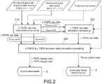
- Fig. 2 is a diagram showing a flow of entire computation processing by the computation processing device 4.
- Main computation processing performed in the computation processing device 4 includes L-PSPD raw data calculation processing (S10), L-TSPD raw data calculation processing (S20), and L-PSPD & L-TSPD provision data calculation processing (S30).
- L-PSPD raw data information on the calculated predicted airspeed and variation amount thereof is called "L-PSPD raw data".
- the L-PSPD is an abbreviation of a
- the computation processing device 4 calculates a target airspeed on the basis of the L-PSPD raw data calculated in the above-mentioned L-PSPD raw data calculation processing (S10) and the flight state parameters provided by the flight state parameter providing unit 3.
- the calculated target airspeed is called "L-TSPD raw data”.
- the L-TSPD is an abbreviation of a lidar-target speed.
- the computation processing device 4 performs processing of displaying, on a cockpit instrument 5, the L-PSPD raw data calculated in the above-mentioned L-PSPD raw data calculation processing (S10) and the L-TSPD raw data calculated in the above-mentioned L-TSPD raw data calculation processing (S20), processing of notifying a pilot of a warning via the cockpit instrument 5 when the L-PSPD raw data is within the warning region, processing of calculating thrust control data to be output to an automatic thrust control device 6 by using the L-TSPD raw data, and the like.
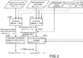
- Fig. 3 is a diagram showing a flow of the L-PSPD raw data calculation processing (S10).
- Fig. 4 is a diagram for describing a calculation method for a predicted airspeed in the L-PSPD raw data calculation processing (S10).
- Fig. 5 is a diagram for describing a calculation method for a variation amount of a predicted airspeed in the L-PSPD raw data calculation processing (S10).
- a wind speed change from a present time (t 0 ) to the time (t 1 ) is ⁇ W h (t 1 )
- a wind speed change from the time (t 1 ) to the time (t 2 ) is ⁇ W h (t 2 )
- a wind speed change from the time (t 2 ) to the time (t 3 ) is ⁇ W h (t 3 ) .
- the computation processing device 4 calculates a predicted airspeed V apredict (t 1 ) at the time (t 1 ) (S103 in Fig. 3 ).
- the wind speed change ⁇ W h (t 1 ) between the present time (t 0 ) to the time (t 1 ) is an "increase by 3 kt in the tailwind direction".
- a result of addition or subtraction of the wind speed change ⁇ W h (t 1 ) to/from the predicted airspeed at the time (t 1 ), which is calculated on the basis of the present airspeed V a , the present acceleration dV g/ d t , and the like without considering the remote turbulence may be the predicted airspeed V apredict (t 1 ) at the time (t 1 ).
- the computation processing device 4 uses a result of addition or subtraction of the wind speed change ⁇ W h (t 2 ) to/from the predicted airspeed at the time (t 2 ), which is calculated on the basis of the present airspeed V a , the present acceleration dV g/ d t , and the like without considering the remote turbulence, as a predicted airspeed V apredict (t 2 ) at the time (t 2 ).
- the predicted airspeed V apredict (t i ) (i 1, ..., n) at each time, which considers influence of the remote turbulence, is calculated.
- the computation processing device 4 sets wind speed variation amount data ⁇ W h (t 1 ) of the remote turbulence of the time (t 0 ) to the time (t 1 ) as predicted airspeed variation amount data ⁇ V apredict (t 1 ) at the time (t 1 ), sets wind speed variation amount data ⁇ W h (t 2 ) of the remote turbulence from the time (t 1 ) to the time (t 2 ) as predicted airspeed variation amount data ⁇ V apredict (t 2 ) at the time (t 2 ), and sets wind speed variation amount data ⁇ W h (t 3 ) of the remote turbulence from the time (t 2 ) to the time (t 3 ) as predicted airspeed variation amount data ⁇ V apredict (t 3 ) at the time (t 3 ) .
- Fig. 6 is a diagram showing a flow of the L-TSPD raw data calculation processing (S20) of Fig. 3 .
- the computation processing device 4 subjects the determined additional speed V add to limiter processing with upper and lower limit values determined in accordance with a present configuration of the aircraft (e.g., gear, flap, aircraft weight, etc.) (not shown).
- a present configuration of the aircraft e.g., gear, flap, aircraft weight, etc.
- the computation processing device 4 adds the additional speed V add subjected to the limiter processing to a reference speed V ref according to pilot setting and the like of a present target airspeed, for example (S203 in Fig. 6 ).
- the computation processing device 4 subjects the above-mentioned result of addition to the limiter processing with the upper and lower limit values determined in accordance with the present configuration of the aircraft (e.g., gear, flap, aircraft weight, etc.) and sets the result thereof as the target airspeed (L-TSPD raw data).
- the aircraft e.g., gear, flap, aircraft weight, etc.
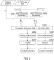
- Fig. 7 is a diagram showing a flow of processing regarding display and warning of the L-PSPD raw data.
- the computation processing device 4 converts the extracted data into data in a format that can be handled by the cockpit instrument 5 (S303 in Fig. 7 ).
- the computation processing device 4 determines whether a predetermined condition for the converted data to be displayed by the cockpit instrument 5 is satisfied (S304 in Fig. 7 ).
- the computation processing device 4 causes a primary flight display which is a main device of the cockpit instrument 5 to display the L-PSPD information if that displaying condition (S305 in Fig. 7 ).
- warning processing of the predicted airspeed if the computation processing device 4 determines that the predicted airspeed V apredict (t i ) considering the variation amount ⁇ V apredict (t i ), for example, either one of a minimum predicted airspeed V apredict (t i ) or a maximum predicted airspeed V apredict (t i ) considering the variation amount ⁇ V apredict (t i ) is within the warning region (S306 in Fig. 7 ), control is performed to perform a warning notification to the pilot via the cockpit instrument 5 (S307 in Fig. 7 ).
- the warning notification may be visually performed via a display of the cockpit instrument 5 and may also be performed with sounds.
- the computation processing device 4 performs control to perform the warning notification if the minimum predicted airspeed V apredict (t i ) considering the variation amount ⁇ V apredict (t i ) is lowered and enters the warning region determined in accordance with the configuration of the aircraft (gear, flap, weight, etc.)
- Fig. 8 is a diagram showing a flow of display processing and warning processing of the L-TSPD information, which are based on the L-TSPD raw data.
- round is conversion processing into an integer value by rounding off.
- ⁇ TSPD is a resolution for discretization.
- the computation processing device 4 determines whether the predetermined condition for the discretized L-TSPD to be displayed by the cockpit instrument 5 is satisfied (S309). This determination is performed on the basis of whether Condition 1 below or two conditions of Conditions 1 and 2 are satisfied, for example.
- Condition 1 the fact that an absolute value of a difference between the L-TSPD and a target speed of the pilot setting is equal to or larger than a threshold.
- Condition 2 the fact that regarding the predicted airspeed V apredict (t i ) and variation amount ⁇ V apredict (t i ) used for calculation of the additional speed V add , either one of the predicted airspeed V apredict (t i ) + 2 * the variation amount ⁇ V apredict (t i ) or the predicted airspeed V apredict (t i ) - 2 * the variation amount ⁇ V apredict (t i ) is larger than the set upper limit value or is lower than the set lower limit value.
- the computation processing device 4 causes the primary flight display which is the main device of the cockpit instrument 5 to display the L-TSPD information (S310).
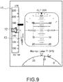
- Fig. 9 is a diagram showing an example of the primary flight display including the display symbol of the L-PSPD information and the L-TSPD information.
- An indicator 12 of the present airspeed V a is arranged at a middle height position of the airspeed indicator 11.
- the present airspeed V a is between 157 kt to 158 kt.
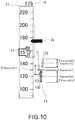
- Fig. 10 is an enlarged diagram of the airspeed indicator 11 and the predicted speed symbol group 13 in the primary flight display.
- a length in a speed axis direction of the airspeed indicator 11 of the respective predicted speed symbols 131, 132, and 133 indicates the variation amount ⁇ V apredict (t i ) and the position on the speed axis of the airspeed indicator 11 at a middle height of the predicted speed symbols 131, 132, and 133 indicates the predicted airspeed V apredict (t i ).
- the predicted speed symbols 131, 132, and 133 has a shape easy to check the middle height at a glance, for example, a vertically-long elliptical shape or the like.
- the horizontal positions of those three predicted speed symbols 131, 132, and 133 correspond to the times. A horizontal position closer to the airspeed indicator 11 indicates that it is closer to the present time.
- the respective predicted speed symbols 131, 132, and 133 may be displayed with a display format, for example, line color, line type, thickness, texture, and the like changed.
- a display format for example, line color, line type, thickness, texture, and the like changed.
- predetermined color, line type, thickness, and texture may be assigned for each of the predicted speed symbols in an order from the predicted speed symbol at the time closer to the present time.
- the speed may be displayed with the color changed for warning or attracting attention.
- a target speed symbol 15 indicating the target airspeed and a speed value 16 thereof are displayed on the airspeed indicator 11.
- the example of the figure indicates that the target airspeed is 175 kt.
- the computation processing device 4 calculates thrust control data on the basis of the target airspeed (L-TSPD raw data) on an automatic operation mode and provides it to the automatic thrust control device 6 (S311). With this, automatic thrust control considering the remote turbulence is realized.
- the remote turbulence in front of the aircraft information measured by the remote turbulence measurement device 2 mounted on the aircraft is given to the computation processing device 4 in real time.
- the computation processing device 4 calculates the predicted airspeed to be given several seconds to several tens of seconds later and the target airspeed by using the remote turbulence information thereof and provides it to the pilot via the cockpit instrument 5. While considering the predicted airspeed to be given several seconds to several tens of seconds later and the target airspeed, the pilot can select a manual throttle operation of optimal thrust control for maintaining a target speed.
- the pilot can know that there is a possibility that the airspeed of the aircraft may be lowered due to a sudden change of the turbulence, in particular, a change from the headwind to the tailwind during landing approach, several seconds to several tens of seconds before it happens. Therefore, it becomes possible to reduce the number of times a go-around should be performed, for example.
- the pilot by causing the primary flight display which is the main instrument of the cockpit instrument 5 to display the information on the predicted airspeed and the target airspeed and causing it to display the predicted speed symbol group 13 indicating the predicted airspeed and the target speed symbol 15 indicating the target airspeed while adjusting them to the speed axis of the airspeed indicator 11, the pilot can instantly know a high/low relationship between the present airspeed and the predicted airspeed to be given several seconds to several tens of seconds later and the target airspeed and can quickly select an optimal manual throttle operation.
- the information on the predicted airspeed including the variation amount is displayed as the predicted speed symbols 131, 132, and 133. Therefore, the pilot can select a manual throttle operation for optimal thrust control while considering the variation amount of the predicted airspeed.
- the information on the predicted airspeeds including the variation amounts at the plurality of times is displayed as the predicted speed symbol group 13 at the same time. Therefore, the manual throttle operation for optimal thrust control can be selected while considering changes in predicted airspeeds including the variation amounts at the plurality of times.
- the pilot can be given with a visual or audio warning when the predicted airspeed considering the variation amount enters the warning region. Therefore, the speed management burden on the pilot can be lightened and the safety can be improved.
- stable automatic thrust control considering the remote turbulence is realized by calculating the thrust control data on the basis of the target airspeed on an automatic operation mode and providing it to the automatic thrust control device 6.
Landscapes
- Engineering & Computer Science (AREA)
- Aviation & Aerospace Engineering (AREA)
- Physics & Mathematics (AREA)
- General Physics & Mathematics (AREA)
- Multimedia (AREA)
- Traffic Control Systems (AREA)
Abstract
Description
- The present invention relates to an aircraft speed information providing system, a speed information providing method, and a program for providing speed information on an predicted airspeed, a target airspeed, and the like considering influence of remote turbulence in front of an aircraft.
- An aircraft speed indication generally includes a target airspeed indication called "selected speed" or "speed bug", a predicted airspeed indication called "speed trend vector", and the like. In general, the target airspeed is speed information provided complying with aircraft performance limits, objectives, instructions from the control, regulations of airline companies, and regulations during flight.
- Further, the predicted airspeed is information on a predicted speed to be given several seconds later (e.g., ten seconds later), which is calculated on the basis of information on increase/decrease in aircraft speed (see Non-Patent Literature 1). For maintaining a constant speed, a pilot conducts a thrust operation for reducing the speed if the predicted airspeed tends to increase ten seconds later or for increasing the speed if the predicted airspeed tends to decrease ten seconds later. Further, the pilot conducts a manual thrust operation such that the aircraft has a target airspeed. Alternatively, not relying on pilot's manual operations, an automatic thrust control device (e.g., auto throttle or the like) can also automatically control thrust so as to obtain a target airspeed.
-
- Patent Literature 1: Japanese Patent Application Laid-open No.
2010-217077 - Patent Literature 2: Japanese Patent Application Laid-open No.
2015-056055 -
- Non-Patent Literature 1: Instrument Flying Handbook (FAA-H-8083-15A, 6-26)
- Non-Patent Literature 2: "Operational Evaluation of Low Level Turbulence Advisory System" (51st Aircraft Symposium, JSASS-2013-5174, November 2013, Kagawa) by Tomoko Iijima, Naoki Matayoshi, and Eiichi Yoshikawa
- Non-Patent Literature 3: "Development and Evaluation of Airport Low level Wind Information" (53rd Aircraft Symposium, 2G03, November 2015, Matsuyama) by Tomoko Iijima, Naoki Matayoshi, Eiji Fujita, and Kentaro Yamamoto
- However, in general, influence of turbulence (remote turbulence) in front of an aircraft is not considered in calculating a predicted airspeed and a target airspeed given to the aircraft, and thus the predicted airspeed and the target airspeed given to the aircraft have errors at least corresponding thereto. For that reason, if the airspeed of the aircraft suddenly changes due to the influence of the turbulence when the pilot tries to enter a runway at a target airspeed determined by the pilot for landing, for example, the pilot may have to conduct a go-around. More specifically, there is a case where the headwind changes into the tailwind while losing the altitude and the airspeed is lowered to approach the stall speed. In such a case, a go-around is conducted.
- Also in thrust control based on the target airspeed by the automatic thrust control device, there is a possibility that an error corresponding to influence due to a turbulence change may be included.
- A remote turbulence measurement device such as a Doppler lidar and a Doppler radar is known as means for measuring turbulence. For example, there is known a method of measuring turbulence by the Doppler lidar in order to provide the pilot with an alarm indication regarding a situation where wind suddenly changes like severe wind shear (see Patent Literature 1). However, in a manner that depends on a situation where turbulence fluctuates, there are not a few cases where it becomes difficult to control the airspeed of the aircraft so as to correspond to the turbulence fluctuation even without alarm and a go-around is conducted.
- Further, there is known a technology of notifying an aircraft of remote turbulence information via a data link from a sensor (e.g., Doppler radar for airport weather, Doppler lidar for airport weather, etc.) that is placed on the ground and measures remote turbulence (e.g., Patent Literature 2). However, regarding that system, it has been reported that there is a delay of about ten minutes from turbulence measurement to information provision (Non-Patent Literature 2) and it has also been reported that an actual turbulence state is different from information (Non-Patent Literature 3).
- In view of the above-mentioned circumstances, it is an object of the present invention to provide an aircraft speed information providing system, a speed information providing method, and a program, by which stable airspeed control considering remote turbulence can be realized.
- In order to solve the above-mentioned problem, an aircraft speed information providing system according to an embodiment of the present invention includes: an airspeed measurement device that measures a present airspeed of an aircraft; an acceleration measurement device that measures present acceleration of the aircraft; a remote turbulence measurement device that is installed in the aircraft and measures remote turbulence in front of the aircraft; and a computation processing device that calculates a predicted airspeed of the aircraft on the basis of the measured present airspeed and present acceleration and the remote turbulence measured by the remote turbulence measurement device.
- In the present invention, the predicted airspeed considering the remote turbulence in front of the aircraft can be calculated. By providing the pilot with this predicted airspeed, the pilot can select a manual throttle operation for optimal thrust control for maintaining a target speed while considering the predicted airspeed considering the remote turbulence in front of the aircraft.
- The computation processing device may be configured to further calculate a variation amount of the predicted airspeed.
- By providing the pilot with the information on the predicted airspeed including the variation amount, the pilot can select a manual throttle operation for more optimal thrust control for maintaining a target speed while considering the predicted airspeed including the variation amount.
- The computation processing device may be configured to calculate the predicted airspeed and the variation amount at each of a plurality of times.
- By providing the pilot with information on the predicted airspeed and the variation amount at each of the plurality of times, the pilot can select a manual throttle operation for more optimal thrust control for maintaining a target reference speed while considering a change in predicted airspeed and the variation amount between the plurality of times.
- Further, the computation processing device may be configured to cause a cockpit instrument to display the calculated predicted airspeed and variation amount.
- The computation processing device may be configured to generate a warning notification when the predicted airspeed considering the calculated variation amount is within a warning region.
- The speed management burden on the pilot can be lightened and the safety can be enhanced.
- The computation processing device may be configured to calculate a target airspeed on the basis of a difference between the calculated predicted airspeed and present airspeed, the calculated variation amount, and a reference speed such as a reference speed by pilot setting.
- By providing the pilot with the target airspeed, for example, the pilot can select a more optimal manual throttle operation for maintaining the reference speed by the pilot setting while considering the target airspeed considering the remote turbulence.
- The computation processing device may be configured to calculate the target airspeed while considering a configuration of the aircraft.
- In addition, the computation processing device may be configured to cause the cockpit instrument to display the calculated target airspeed.
- Further, the computation processing device may be configured to calculate control data for automatic thrust control on the basis of the calculated target airspeed.
- By outputting this control data to the automatic thrust control device, more stable automatic thrust control considering the remote turbulence in front of the aircraft is realized.
- An aircraft speed information providing method according to another embodiment of the present invention includes: by a computation processing device installed in an aircraft, inputting data on remote turbulence in front of an aircraft measured by a remote turbulence measurement device installed in the aircraft; and calculating a predicted airspeed of the aircraft on the basis of the data on the remote turbulence and respective data on a present airspeed and acceleration of the aircraft.
- A program according to another embodiment of the present invention causes a computer to operate as a computation processing device that inputs data on remote turbulence in front of an aircraft measured by a remote turbulence measurement device installed in the aircraft, and calculates a predicted airspeed of the aircraft on the basis of the data on the remote turbulence and respective data on a present airspeed and acceleration of the aircraft.
- As described above, in accordance with the present invention, it is possible to provide an aircraft speed information providing system, a speed information providing method, and a program, by which stable airspeed control considering remote turbulence can be realized.
-
- [
Fig. 1 ] A block diagram showing an entire configuration of an aircraft speedinformation providing system 1 according to an embodiment of the present invention. - [
Fig. 2 ] A diagram showing a flow of entire computation processing by acomputation processing device 4 in the speedinformation providing system 1 ofFig. 1 . - [
Fig. 3 ] A diagram showing a flow of L-PSPD raw data calculation processing (S10) ofFig. 2 . - [
Fig. 4 ] A diagram for describing a calculation method for a predicted airspeed in the L-PSPD raw data calculation processing (S10) ofFig. 2 . - [
Fig. 5 ] A diagram for describing a calculation method for a variation amount of a predicted airspeed in the L-PSPD raw data calculation processing (S10) ofFig. 2 . - [
Fig. 6 ] A diagram showing a flow of L-TSPD raw data calculation processing (S20) ofFig. 2 . - [
Fig. 7 ] A diagram showing a flow of processing regarding display and warning from the L-PSPD raw data in L-PSPD & L-TSPD provision data calculation processing inFig. 2 . - [
Fig. 8 ] A diagram showing a flow of display processing and warning processing for L-TSPD information based on L-TSPD raw data in the L-PSPD & L-TSPD provision data calculation processing ofFig. 2 . - [
Fig. 9 ] A diagram showing an example of primary flight display including a display symbol of L-PSPD information and L-TSPD information. - [
Fig. 10 ] An enlarged diagram of a predictedairspeed indicator 11 and a predictedspeed symbol group 13 in the primary flight display ofFig. 9 . - [
Fig. 11 ] A block diagram showing an entire configuration of a typical aircraft predicted airspeed information providing system (e.g., speed trend vector). - Hereinafter, an embodiment of the present invention will be described.
- An aircraft speed information providing system of this embodiment is a system capable of providing the pilot and the automatic thrust control device with speed information on a predicted airspeed to be given several seconds to several tens of seconds later, a target airspeed, and the like, for example, considering remote turbulence in front of an aircraft.
-
Fig. 11 is a block diagram showing a typical method of generating the speed information on the predicted airspeed given several seconds to several tens of seconds later and the like. In this typical method, on the basis of a present airspeed Va and present dVg/dt, the computation processing device calculates, for example, a predicted airspeed Vapredict (ti) (i = 1) at a time (t1) determined in a range of several seconds to several tens of seconds. In accordance with this method, a calculation result includes an error at least corresponding to influence of the remote turbulence in front of the aircraft, which is not considered. The aircraft speed information providing system of this embodiment can at least overcome such an error, which is one of effects. -
Fig. 1 is a block diagram showing an entire configuration of the aircraft speedinformation providing system 1 of this embodiment. - As shown in the figure, this aircraft speed
information providing system 1 includes a remoteturbulence measurement device 2, a flight state parameter providing unit 3, and acomputation processing device 4. - The remote
turbulence measurement device 2 is a device that measures a wind speed and a direction of a direction component along the aircraft axis in the remote turbulence in front of the aircraft. More specifically, the remoteturbulence measurement device 2 is a Doppler lidar or the like. The Doppler lidar is capable of emitting (transmitting) laser light as a transmission signal into the atmosphere, receiving scattered laser light of the laser light due to aerosol in the atmosphere as a reception signal, and measuring turbulence in a remote region at approximately several km to several tens of km in front, for example, on the basis of a Doppler shift amount between the transmission signal and the reception signal. - It should be noted that in the present invention, the remote
turbulence measurement device 2 is not limited to the Doppler lidar and may be another type of turbulence sensor. Further, it is not limited to the type installed in the aircraft and may acquire turbulence data through a data link from a turbulence sensor placed on the ground or a turbulence sensor installed in another aircraft. - The remote
turbulence measurement device 2 generates data on a wind speed mean value in an aircraft axis direction and the like for each different distance (li) (i = 1, ..., n) as wind speed data Wh (li) (i = 1, ..., n) of the remote turbulence at each distance on the basis of the measured turbulence data. The remoteturbulence measurement device 2 outputs it to thecomputation processing device 4 in real time. For example, provided that an entire measurement distance is 6 km, the distance of 6 km is divided into a range of a distance (li) of 0 to 2 km, a range of a distance (l2) of 2 km to 4 km, and a range of a distance (l3) of 4 km to 6 km. A wind speed mean value and the like, for example, in each distance range are generated as wind speed data Wh (li) (i = 1, 2, 3) of the remote turbulence at each distance (li) (i = 1, 2, 3). Those are output to thecomputation processing device 4 in real time. Here, each distance range does not necessarily need to be the same. - Further, the remote
turbulence measurement device 2 generates wind speed variation amount data δWh (li) (i = 1, ..., n) of the remote turbulence at each distance (li) (i = 1, ..., n) and outputs it to thecomputation processing device 4 in real time. The wind speed variation amount data δWh (li) (i = 1, ..., n) indicates, for example, a standard deviation of a variation amount of the wind speed of the remote turbulence in the aircraft axis direction, which is measured within a target distance range. - The flight state parameter providing unit 3 includes various measurement devices, calculation devices, and the like that measure various parameters (flight state parameters) indicating a state of the aircraft during flight and output them to the
computation processing device 4. The flight state parameter providing unit 3 includes anairspeed measurement unit 31, anaccelerometer 32, a windspeed calculation unit 33, a groundspeed calculation unit 34, aconfiguration providing unit 35, and the like. Theairspeed measurement unit 31 is a device that measures a present airspeed Va of the aircraft. Theaccelerometer 32 is a device that measures present acceleration dVg/dt of the aircraft. The windspeed calculation unit 33 is a device that measures a present wind speed Wh (l0) in the aircraft axis direction, which is experienced by the aircraft. The groundspeed calculation unit 34 is a device that calculates a present ground speed Vg of the aircraft by using global positioning system (GPS) information and the like, for example. Theconfiguration providing unit 35 is a device that provides information on a configuration such as present gear state, flap state, weight, and the like of the aircraft. - The
computation processing device 4 includes a control unit, a storage unit, an input unit, an output unit, a transmission and reception unit, and the like. The control unit includes a central processing unit (CPU) and the like. By operating in accordance with software developed in the storage unit, the control unit executes various types of computation processing such as processing of calculating a predicted airspeed and processing of calculating a target airspeed. The storage unit includes a read only memory (ROM) and a random access memory (RAM). The transmission and reception unit transmits and receives data to/from therespective devices 31 to 35 inside the remoteturbulence measurement device 2 and the flight state parameter providing unit 3. - The
computation processing device 4 is configured to perform computation processing as follows on the basis of the wind speed data Wh (li) (i = 1, ..., n) of the remote turbulence at each distance and the wind speed variation amount data δWh (li) (i = 1, ..., n) at each distance, which are input by the remoteturbulence measurement device 2, and the flight state parameters provided by therespective devices 31 to 35 inside the flight state parameter providing unit 3. -
Fig. 2 is a diagram showing a flow of entire computation processing by thecomputation processing device 4. - Main computation processing performed in the
computation processing device 4 includes L-PSPD raw data calculation processing (S10), L-TSPD raw data calculation processing (S20), and L-PSPD & L-TSPD provision data calculation processing (S30). - L-PSPD Raw Data Calculation Processing (S10) On the basis of the wind speed data Wh (li) (i = 1, ..., n) of the remote turbulence at each distance and the wind speed variation amount data δWh (li) (i = 1, ..., n) at each distance, which are input by the remote
turbulence measurement device 2, and the flight state parameters provided by the flight state parameter providing unit 3, thecomputation processing device 4 calculates a predicted airspeed Vapredict (ti) (i = 1, ..., n) at each time (ti) (i = 1, ..., n) corresponding to each distance (li) (i = 1, ..., n) and a variation amount thereof δVapredict (ti) (i = 1, ..., n). Here, information on the calculated predicted airspeed and variation amount thereof is called "L-PSPD raw data". The L-PSPD is an abbreviation of a lidar-predictive speed. - The
computation processing device 4 calculates a target airspeed on the basis of the L-PSPD raw data calculated in the above-mentioned L-PSPD raw data calculation processing (S10) and the flight state parameters provided by the flight state parameter providing unit 3. Here, the calculated target airspeed is called "L-TSPD raw data". The L-TSPD is an abbreviation of a lidar-target speed. - The
computation processing device 4 performs processing of displaying, on acockpit instrument 5, the L-PSPD raw data calculated in the above-mentioned L-PSPD raw data calculation processing (S10) and the L-TSPD raw data calculated in the above-mentioned L-TSPD raw data calculation processing (S20), processing of notifying a pilot of a warning via thecockpit instrument 5 when the L-PSPD raw data is within the warning region, processing of calculating thrust control data to be output to an automaticthrust control device 6 by using the L-TSPD raw data, and the like. - Next, each type of the above-mentioned processing (S10), (S20), and (S30) will be described in detail.
-
Fig. 3 is a diagram showing a flow of the L-PSPD raw data calculation processing (S10). -
Fig. 4 is a diagram for describing a calculation method for a predicted airspeed in the L-PSPD raw data calculation processing (S10). -
Fig. 5 is a diagram for describing a calculation method for a variation amount of a predicted airspeed in the L-PSPD raw data calculation processing (S10). - As shown in
Fig. 3 , thecomputation processing device 4 inputs the wind speed data Wh (li) (i = 1, ..., n) of the remote turbulence in each distance range from the remoteturbulence measurement device 2. Next, thecomputation processing device 4 converts the input wind speed data Wh (li) (i = 1, ..., n) of the remote turbulence in each distance range into wind speed data Wh (ti) (i = 1, ..., n) at each time (S101 inFig. 3 ). In order to perform this distance-to-time conversion, thecomputation processing device 4 inputs present ground speed data Vg and present acceleration data dVg/dt through the flight state parameter providing unit 3 and calculates a time (ti) (i = 1, ..., n) when the aircraft reaches a point at each distance (li) (i = 1, ..., n) described above on the basis of that data. - As shown in
Fig. 4 , a case of calculating a predicted airspeed Vapredict (ti) (i = 1, 2, 3) at each of three times will be considered. - On the basis of the converted wind speed data Wh (ti) (i = 1, 2, 3) at each time and present wind speed data Wh (t0) input from the flight state parameter providing unit 3, the
computation processing device 4 determines a wind speed change ΔWh (ti) (i = 1, 2, 3) between the times (S102 inFig. 3 ). Here, it is assumed that a wind speed change from a present time (t0) to the time (t1) is ΔWh (t1), a wind speed change from the time (t1) to the time (t2) is ΔWh (t2), and a wind speed change from the time (t2) to the time (t3) is ΔWh (t3) . - Next, on the basis of present airspeed data Va input by the flight state parameter providing unit 3 and the present acceleration data dVg/dt and a wind speed change ΔWh (t1), the
computation processing device 4 calculates a predicted airspeed Vapredict (t1) at the time (t1) (S103 inFig. 3 ). For example, in a case where the present wind speed data Wh (t0) is 5 kt in a tailwind direction and a wind speed data Wh (t1) of the remote turbulence at the time (t1) is 8 kt in the tailwind direction, the wind speed change ΔWh (t1) between the present time (t0) to the time (t1) is an "increase by 3 kt in the tailwind direction". In this case, for example, a result of addition or subtraction of the wind speed change ΔWh (t1) to/from the predicted airspeed at the time (t1), which is calculated on the basis of the present airspeed Va, the present acceleration dVg/dt, and the like without considering the remote turbulence may be the predicted airspeed Vapredict (t1) at the time (t1). - Also regarding the time (t2), the
computation processing device 4 uses a result of addition or subtraction of the wind speed change ΔWh (t2) to/from the predicted airspeed at the time (t2), which is calculated on the basis of the present airspeed Va, the present acceleration dVg/dt, and the like without considering the remote turbulence, as a predicted airspeed Vapredict (t2) at the time (t2). In this manner, the predicted airspeed Vapredict (ti) (i = 1, ..., n) at each time, which considers influence of the remote turbulence, is calculated. - The
computation processing device 4 inputs the wind speed variation amount data δWh (li) (i = 1, ..., n) of the remote turbulence at each distance through the remoteturbulence measurement device 2. Thecomputation processing device 4 converts data on the input wind speed variation amount δWh (li) (i = 1, ..., n) of the remote turbulence at each distance into data on wind speed variation amount data δWh (ti) (i = 1, ..., n) at each time (ti) (i = 1, ..., n) (Step S104 ofFig. 3 ). In order to perform this distance-to-time conversion, thecomputation processing device 4 inputs the present ground speed data Vg of the aircraft and the present acceleration data dVg/dt of the aircraft through the flight state parameter providing unit 3 and calculates a time (ti) (i = 1, ..., n) when the aircraft reaches a point at each distance (li) (i = 1, ..., n) described above on the basis of that data. - The
computation processing device 4 obtains the converted wind speed variation amount data δWh (ti) (i = 1, ..., n) of the remote turbulence at each time as predicted airspeed variation amount data δVapredict (ti) (i = 1, ..., n) at each time (Step S105 ofFig. 3 ). For example, as shown inFig. 5 , for calculating the predicted airspeed Vapredict (ti) (i = 1, 2, 3) at each of three times, thecomputation processing device 4 sets wind speed variation amount data δWh (t1) of the remote turbulence of the time (t0) to the time (t1) as predicted airspeed variation amount data δVapredict (t1) at the time (t1), sets wind speed variation amount data δWh (t2) of the remote turbulence from the time (t1) to the time (t2) as predicted airspeed variation amount data δVapredict (t2) at the time (t2), and sets wind speed variation amount data δWh (t3) of the remote turbulence from the time (t2) to the time (t3) as predicted airspeed variation amount data δVapredict (t3) at the time (t3) . -
Fig. 6 is a diagram showing a flow of the L-TSPD raw data calculation processing (S20) ofFig. 3 . - The
computation processing device 4 compares the predicted airspeed Vapredict (ti) (i = 1, ..., n) at each time in the L-PSPD raw data calculated in the L-PSPD raw data calculation processing (S10) with the present airspeed Va provided from the flight state parameter providing unit 3 (S201 inFig. 6 ). Next, thecomputation processing device 4 calculates necessary additional speed Vadd on the basis of the respective comparison results and the variation amount of the predicted airspeed δVapredict (ti) (i = 1, ..., n) at the corresponding time calculated in the L-PSPD raw data calculation processing (S10) (S202 inFig. 6 ). More specifically, if the predicted airspeed Vapredict (ti) (i = 1, ..., n) is lower than the present airspeed Va, a value obtained by adding the variation amount of the predicted airspeed δVapredict (ti) (i = 1, ..., n) to a speed difference between the present airspeed Va and the predicted airspeed Vapredict (ti) (i = 1, ..., n) is set as the necessary additional speed Vadd which is positive. - It should be noted that information to be used for calculation of the additional speed Vadd may be the predicted airspeeds Vapredict (ti) (i = 1, ..., n) and the amounts of fluctuation δVapredict (ti) (i = 1, ..., n) at all the times or may be the predicted airspeed Vapredict (ti) and the variation amount δVapredict (ti) at any one or more times.
- Next, the
computation processing device 4 subjects the determined additional speed Vadd to limiter processing with upper and lower limit values determined in accordance with a present configuration of the aircraft (e.g., gear, flap, aircraft weight, etc.) (not shown). - Next, the
computation processing device 4 adds the additional speed Vadd subjected to the limiter processing to a reference speed Vref according to pilot setting and the like of a present target airspeed, for example (S203 inFig. 6 ). - The
computation processing device 4 subjects the above-mentioned result of addition to the limiter processing with the upper and lower limit values determined in accordance with the present configuration of the aircraft (e.g., gear, flap, aircraft weight, etc.) and sets the result thereof as the target airspeed (L-TSPD raw data). - Next, the L-PSPD & L-TSPD provision data calculation processing of calculating data available by the
cockpit instrument 5 and the automaticthrust control device 6 on the basis of the L-PSPD raw data and L-TSPD raw data calculated in the above-mentioned manner will be described in detail. -
Fig. 7 is a diagram showing a flow of processing regarding display and warning of the L-PSPD raw data. - The
computation processing device 4 extracts each piece of data at a common time on the basis of the predicted airspeed Vapredict (ti) and the variation amount δVapredict (ti) at each time (ti) (i = 1, ..., n), which are the L-PSPD raw data (S301 and S302 inFig. 7 ). Thecomputation processing device 4 converts the extracted data into data in a format that can be handled by the cockpit instrument 5 (S303 inFig. 7 ). - Next, the
computation processing device 4 determines whether a predetermined condition for the converted data to be displayed by thecockpit instrument 5 is satisfied (S304 inFig. 7 ). Thecomputation processing device 4 causes a primary flight display which is a main device of thecockpit instrument 5 to display the L-PSPD information if that displaying condition (S305 inFig. 7 ). - It should be noted that the fact that a mean value of a difference between the predicted airspeed Vapredict (ti) (i = 1, ..., n) at each time and the present airspeed Va is equal to or higher than a threshold or the like can be exemplified as the condition for displaying the L-PSPD information, though the L-PSPD information may be constantly displayed with no conditions without setting the threshold.
- Further, regarding warning processing of the predicted airspeed, if the
computation processing device 4 determines that the predicted airspeed Vapredict (ti) considering the variation amount δVapredict (ti), for example, either one of a minimum predicted airspeed Vapredict (ti) or a maximum predicted airspeed Vapredict (ti) considering the variation amount δVapredict (ti) is within the warning region (S306 inFig. 7 ), control is performed to perform a warning notification to the pilot via the cockpit instrument 5 (S307 inFig. 7 ). The warning notification may be visually performed via a display of thecockpit instrument 5 and may also be performed with sounds. For example, thecomputation processing device 4 performs control to perform the warning notification if the minimum predicted airspeed Vapredict (ti) considering the variation amount δVapredict (ti) is lowered and enters the warning region determined in accordance with the configuration of the aircraft (gear, flap, weight, etc.) -
Fig. 8 is a diagram showing a flow of display processing and warning processing of the L-TSPD information, which are based on the L-TSPD raw data. - First of all, the
computation processing device 4 performs discretization processing on the L-TSPD raw data (S308). This processing is performed as follows, for example.
- ΔTSPD is a resolution for discretization.
- Next, the
computation processing device 4 determines whether the predetermined condition for the discretized L-TSPD to be displayed by thecockpit instrument 5 is satisfied (S309). This determination is performed on the basis of whetherCondition 1 below or two conditions ofConditions - Condition 1: the fact that an absolute value of a difference between the L-TSPD and a target speed of the pilot setting is equal to or larger than a threshold.
- Condition 2: the fact that regarding the predicted airspeed Vapredict (ti) and variation amount δVapredict (ti) used for calculation of the additional speed Vadd, either one of the predicted airspeed Vapredict (ti) + 2 * the variation amount δVapredict (ti) or the predicted airspeed Vapredict (ti) - 2 * the variation amount δVapredict (ti) is larger than the set upper limit value or is lower than the set lower limit value.
- If determining that the above-mentioned two conditions are satisfied, the
computation processing device 4 causes the primary flight display which is the main device of thecockpit instrument 5 to display the L-TSPD information (S310). -
Fig. 9 is a diagram showing an example of the primary flight display including the display symbol of the L-PSPD information and the L-TSPD information. - An
airspeed indicator 11, in which higher speeds are assigned to upper height positions and which is also called speed tape, is arranged in the primary flight display. Anindicator 12 of the present airspeed Va is arranged at a middle height position of theairspeed indicator 11. In the example shown in the figure, the present airspeed Va is between 157 kt to 158 kt. The predictedspeed symbol group 13 indicating the predicted airspeed (ti) (i = 1, ..., n) and the variation amount thereof δVapredict (ti) (i = 1, ..., n) at each time is arranged near theairspeed indicator 11. -
Fig. 10 is an enlarged diagram of theairspeed indicator 11 and the predictedspeed symbol group 13 in the primary flight display. - Here, the predicted
speed symbol group 13 includes predictedspeed symbols speed symbol 131 indicates the predicted airspeed Vapredict (ti) and the variation amount δVapredict (ti) at the time (t1), the predictedspeed symbol 132 indicates the predicted airspeed Vapredict (t2) and the variation amount δVapredict (t2) at the time (t2), and the predictedspeed symbol 133 indicates the predicted airspeed Vapredict (t3) and the variation amount δVapredict (t3) at the time (t3) . - A length in a speed axis direction of the
airspeed indicator 11 of the respective predictedspeed symbols airspeed indicator 11 at a middle height of the predictedspeed symbols speed symbols speed symbols airspeed indicator 11 indicates that it is closer to the present time. - The respective predicted
speed symbols - Further, if the speed enters a region corresponding to a stall speed, a never-exceed speed, or the like, it may be displayed with the color changed for warning or attracting attention.
- Further, a
target speed symbol 15 indicating the target airspeed and aspeed value 16 thereof are displayed on theairspeed indicator 11. The example of the figure indicates that the target airspeed is 175 kt. - In addition, as shown in
Fig. 8 , thecomputation processing device 4 calculates thrust control data on the basis of the target airspeed (L-TSPD raw data) on an automatic operation mode and provides it to the automatic thrust control device 6 (S311). With this, automatic thrust control considering the remote turbulence is realized. - As described above, in the speed
information providing system 1 of this embodiment, the remote turbulence in front of the aircraft information measured by the remoteturbulence measurement device 2 mounted on the aircraft is given to thecomputation processing device 4 in real time. Thecomputation processing device 4 calculates the predicted airspeed to be given several seconds to several tens of seconds later and the target airspeed by using the remote turbulence information thereof and provides it to the pilot via thecockpit instrument 5. While considering the predicted airspeed to be given several seconds to several tens of seconds later and the target airspeed, the pilot can select a manual throttle operation of optimal thrust control for maintaining a target speed. For example, the pilot can know that there is a possibility that the airspeed of the aircraft may be lowered due to a sudden change of the turbulence, in particular, a change from the headwind to the tailwind during landing approach, several seconds to several tens of seconds before it happens. Therefore, it becomes possible to reduce the number of times a go-around should be performed, for example. - Further, in the speed
information providing system 1 of this embodiment, by causing the primary flight display which is the main instrument of thecockpit instrument 5 to display the information on the predicted airspeed and the target airspeed and causing it to display the predictedspeed symbol group 13 indicating the predicted airspeed and thetarget speed symbol 15 indicating the target airspeed while adjusting them to the speed axis of theairspeed indicator 11, the pilot can instantly know a high/low relationship between the present airspeed and the predicted airspeed to be given several seconds to several tens of seconds later and the target airspeed and can quickly select an optimal manual throttle operation. - Further, in the speed
information providing system 1 of this embodiment, the information on the predicted airspeed including the variation amount is displayed as the predictedspeed symbols - In addition, in the speed
information providing system 1 of this embodiment, the information on the predicted airspeeds including the variation amounts at the plurality of times is displayed as the predictedspeed symbol group 13 at the same time. Therefore, the manual throttle operation for optimal thrust control can be selected while considering changes in predicted airspeeds including the variation amounts at the plurality of times. - In addition, in the speed
information providing system 1 of this embodiment, the pilot can be given with a visual or audio warning when the predicted airspeed considering the variation amount enters the warning region. Therefore, the speed management burden on the pilot can be lightened and the safety can be improved. - In addition, in the speed
information providing system 1 of this embodiment, stable automatic thrust control considering the remote turbulence is realized by calculating the thrust control data on the basis of the target airspeed on an automatic operation mode and providing it to the automaticthrust control device 6. - In addition, the present technology is not limited only to the above-mentioned embodiment and various modifications can be made without departing from the gist of the present invention as a matter of course.
-
- 1
- speed information providing system
- 2
- remote turbulence measurement device
- 3
- flight state parameter providing unit
- 4
- computation processing device
- 5
- cockpit instrument
- 6
- automatic thrust control device
- 11
- airspeed indicator
- 13
- predicted speed symbol group
- 15
- target speed symbol
- 31
- airspeed measurement unit
- 32
- accelerometer
- 33
- wind speed calculation unit
- 33
- ground speed calculation unit
- 33
- wind speed measurement unit
- 34
- ground speed calculation unit
- 35
- configuration providing unit
- 131, 132, 133
- predicted speed symbol
Claims (11)
- An aircraft speed information providing system, comprising:an airspeed measurement device that measures a present airspeed of an aircraft;an acceleration measurement device that measures present acceleration of the aircraft;a remote turbulence measurement device that is installed in the aircraft and measures remote turbulence in front of the aircraft; anda computation processing device that calculates a predicted airspeed of the aircraft on a basis of the measured present airspeed and present acceleration and the remote turbulence measured by the remote turbulence measurement device.
- The aircraft speed information providing system according to claim 1, wherein
the computation processing device is configured to further calculate a variation amount of the predicted airspeed. - The aircraft speed information providing system according to claim 2, wherein
the computation processing device is configured to calculate the predicted airspeed and the variation amount at each of a plurality of times. - The aircraft speed information providing system according to claim 2 or 3, wherein
the computation processing device is configured to cause a cockpit instrument to display the calculated predicted airspeed and variation amount. - The aircraft speed information providing system according to any one of claims 2 to 4, wherein
the computation processing device is configured to generate a warning notification when the predicted airspeed considering the calculated variation amount is within a warning region. - The aircraft speed information providing system according to any one of claims 2 to 5, wherein
the computation processing device is configured to calculate a target airspeed on a basis of a difference between the calculated predicted airspeed and present airspeed, the calculated variation amount, and a reference speed. - The aircraft speed information providing system according to claim 6, wherein
the computation processing device is configured to calculate the target airspeed while considering a configuration of the aircraft. - The aircraft speed information providing system according to claim 6 or 7, wherein
the computation processing device is configured to cause the cockpit instrument to display the calculated target airspeed. - The aircraft speed information providing system according to any one of claims 6 to 8, wherein
the computation processing device is configured to calculate control data for automatic thrust control on a basis of the calculated target airspeed. - An aircraft speed information providing method, comprising:by a computation processing device installed in an aircraft,inputting data on remote turbulence in front of an aircraft measured by a remote turbulence measurement device installed in the aircraft; andcalculating a predicted airspeed of the aircraft on a basis of the data on the remote turbulence and respective data on a present airspeed and acceleration of the aircraft.
- A program that causes a computer to operate as a computation processing device thatinputs data on remote turbulence in front of an aircraft measured by a remote turbulence measurement device installed in the aircraft, andcalculates a predicted airspeed of the aircraft on a basis of the data on the remote turbulence and respective data on a present airspeed and acceleration of the aircraft.
Applications Claiming Priority (2)
| Application Number | Priority Date | Filing Date | Title |
|---|---|---|---|
| JP2016179268 | 2016-09-14 | ||
| PCT/JP2017/016992 WO2018051572A1 (en) | 2016-09-14 | 2017-04-28 | Aircraft speed information providing system, speed information providing method, and program |
Publications (3)
| Publication Number | Publication Date |
|---|---|
| EP3514068A1 true EP3514068A1 (en) | 2019-07-24 |
| EP3514068A4 EP3514068A4 (en) | 2020-05-13 |
| EP3514068B1 EP3514068B1 (en) | 2021-03-24 |
Family
ID=61619074
Family Applications (1)
| Application Number | Title | Priority Date | Filing Date |
|---|---|---|---|
| EP17850479.1A Active EP3514068B1 (en) | 2016-09-14 | 2017-04-28 | Aircraft speed information providing system, speed information providing method, and program |
Country Status (4)
| Country | Link |
|---|---|
| US (1) | US20190367178A1 (en) |
| EP (1) | EP3514068B1 (en) |
| JP (1) | JP6731679B2 (en) |
| WO (1) | WO2018051572A1 (en) |
Families Citing this family (4)
| Publication number | Priority date | Publication date | Assignee | Title |
|---|---|---|---|---|
| US11136040B2 (en) * | 2018-05-21 | 2021-10-05 | Deere & Company | IMU based traction control for wheeled or tracked machine |
| US10899460B2 (en) * | 2018-07-02 | 2021-01-26 | The Boeing Company | System and method for improved pilot situational awareness |
| US11060870B2 (en) * | 2019-08-25 | 2021-07-13 | The Boeing Company | Process and machine to predict and preempt an aerodynamic disturbance |
| WO2021049156A1 (en) * | 2019-09-13 | 2021-03-18 | 本田技研工業株式会社 | Airspace information provision system, airspace information provision method, and airspace information provision program |
Family Cites Families (6)
| Publication number | Priority date | Publication date | Assignee | Title |
|---|---|---|---|---|
| US5070458A (en) * | 1989-03-31 | 1991-12-03 | Honeywell Inc. | Method of analyzing and predicting both airplane and engine performance characteristics |
| JP5618313B2 (en) * | 2009-03-18 | 2014-11-05 | 独立行政法人宇宙航空研究開発機構 | Alarm display method and system for remote airflow |
| JP5376459B2 (en) * | 2010-03-09 | 2013-12-25 | 独立行政法人 宇宙航空研究開発機構 | Optical air data sensor |
| JP5717174B2 (en) * | 2010-11-08 | 2015-05-13 | 独立行政法人 宇宙航空研究開発機構 | Remote turbulence detection method and apparatus for implementing the same |
| US20130311013A1 (en) * | 2012-05-16 | 2013-11-21 | Optical Air Data Systems, Llc | Measurement Assisted Aerodynamic State Estimator |
| US9646505B2 (en) * | 2014-12-23 | 2017-05-09 | Ge Aviation Systems Llc | Method of automatically controlling the descent phase of an aircraft using aircraft avionics executing a descent algorithm |
-
2017
- 2017-04-28 WO PCT/JP2017/016992 patent/WO2018051572A1/en not_active Ceased
- 2017-04-28 JP JP2018539514A patent/JP6731679B2/en active Active
- 2017-04-28 EP EP17850479.1A patent/EP3514068B1/en active Active
- 2017-04-28 US US16/332,157 patent/US20190367178A1/en not_active Abandoned
Also Published As
| Publication number | Publication date |
|---|---|
| EP3514068B1 (en) | 2021-03-24 |
| JP6731679B2 (en) | 2020-07-29 |
| WO2018051572A1 (en) | 2018-03-22 |
| JPWO2018051572A1 (en) | 2019-06-27 |
| US20190367178A1 (en) | 2019-12-05 |
| EP3514068A4 (en) | 2020-05-13 |
Similar Documents
| Publication | Publication Date | Title |
|---|---|---|
| US8014912B2 (en) | Method and device for aiding the piloting of an airplane during an approach phase | |
| US6088654A (en) | Terrain anti-collision process and device for aircraft, with improved display | |
| US9469414B2 (en) | Device for monitoring the stabilisation of the approach phase of an aircraft to a landing runway, associated method and computer program | |
| US11282400B2 (en) | Runway overrun awareness alerting system with discrete indicator | |
| US20110125348A1 (en) | Automatic Emergency Reporting | |
| US20070260366A1 (en) | Method and device for determining the air turbulence likely to be encountered by an aircraft | |
| EP3258457B1 (en) | Systems and methods for situational awareness of current and future vehicle state | |
| US8755954B1 (en) | System and method for generating alert signals in a terrain awareness and warning system of an aircraft using a forward-looking radar system | |
| EP3514068B1 (en) | Aircraft speed information providing system, speed information providing method, and program | |
| EP3862784B1 (en) | Methods and systems for monitoring a fault condition of a radar altitude device | |
| US10227140B2 (en) | System and method for detecting and alerting the user of an aircraft of an impendent adverse condition | |
| US9482551B1 (en) | Airspace performance depictions using vertical and lateral guidance bars | |
| EP3477261B1 (en) | Flight instrument warning display | |
| CN105807087B (en) | It is determined as optimizing the method and apparatus of wind speed that the take-off weight of aircraft need to consider | |
| EP4089497B1 (en) | Methods and systems for depicting avionics data anomalies | |
| EP2650738A1 (en) | System and method for real-time aircraft efficiency analysis and compilation | |
| EP3346278A1 (en) | System and methods to evaluate or improve own ship sensor data in connected vehicles | |
| CA2501908C (en) | Method and apparatus for predictive altitude display | |
| CA2897242C (en) | System and method for detecting and alerting the user of an aircraft of an impendent adverse condition | |
| Roychoudhury et al. | Predicting real-time safety of the national airspace system | |
| Ale et al. | Analysis of the crash of TK 1951 using CATS | |
| RU2598130C1 (en) | Smart crew support system | |
| EP3623846B1 (en) | A supplemental system for a satellite based approach during low visibility conditions | |
| Stratton et al. | Stochastic prediction techniques for wind shear hazard assessment | |
| US20250282488A1 (en) | Configuration sensitive range rings and glide rings |
Legal Events
| Date | Code | Title | Description |
|---|---|---|---|
| STAA | Information on the status of an ep patent application or granted ep patent |
Free format text: STATUS: THE INTERNATIONAL PUBLICATION HAS BEEN MADE |
|
| PUAI | Public reference made under article 153(3) epc to a published international application that has entered the european phase |
Free format text: ORIGINAL CODE: 0009012 |
|
| STAA | Information on the status of an ep patent application or granted ep patent |
Free format text: STATUS: REQUEST FOR EXAMINATION WAS MADE |
|
| 17P | Request for examination filed |
Effective date: 20190412 |
|
| AK | Designated contracting states |
Kind code of ref document: A1 Designated state(s): AL AT BE BG CH CY CZ DE DK EE ES FI FR GB GR HR HU IE IS IT LI LT LU LV MC MK MT NL NO PL PT RO RS SE SI SK SM TR |
|
| AX | Request for extension of the european patent |
Extension state: BA ME |
|
| DAV | Request for validation of the european patent (deleted) | ||
| DAX | Request for extension of the european patent (deleted) | ||
| A4 | Supplementary search report drawn up and despatched |
Effective date: 20200409 |
|
| RIC1 | Information provided on ipc code assigned before grant |
Ipc: B64D 45/00 20060101AFI20200403BHEP Ipc: G01P 5/00 20060101ALI20200403BHEP Ipc: G01S 17/58 20060101ALI20200403BHEP |
|
| GRAP | Despatch of communication of intention to grant a patent |
Free format text: ORIGINAL CODE: EPIDOSNIGR1 |
|
| STAA | Information on the status of an ep patent application or granted ep patent |
Free format text: STATUS: GRANT OF PATENT IS INTENDED |
|
| INTG | Intention to grant announced |
Effective date: 20201106 |
|
| GRAS | Grant fee paid |
Free format text: ORIGINAL CODE: EPIDOSNIGR3 |
|
| GRAA | (expected) grant |
Free format text: ORIGINAL CODE: 0009210 |
|
| STAA | Information on the status of an ep patent application or granted ep patent |
Free format text: STATUS: THE PATENT HAS BEEN GRANTED |
|
| AK | Designated contracting states |
Kind code of ref document: B1 Designated state(s): AL AT BE BG CH CY CZ DE DK EE ES FI FR GB GR HR HU IE IS IT LI LT LU LV MC MK MT NL NO PL PT RO RS SE SI SK SM TR |
|
| REG | Reference to a national code |
Ref country code: GB Ref legal event code: FG4D |
|
| REG | Reference to a national code |
Ref country code: CH Ref legal event code: EP |
|
| REG | Reference to a national code |
Ref country code: IE Ref legal event code: FG4D |
|
| REG | Reference to a national code |
Ref country code: AT Ref legal event code: REF Ref document number: 1374258 Country of ref document: AT Kind code of ref document: T Effective date: 20210415 Ref country code: DE Ref legal event code: R096 Ref document number: 602017035428 Country of ref document: DE |
|
| REG | Reference to a national code |
Ref country code: LT Ref legal event code: MG9D |
|
| PG25 | Lapsed in a contracting state [announced via postgrant information from national office to epo] |
Ref country code: NO Free format text: LAPSE BECAUSE OF FAILURE TO SUBMIT A TRANSLATION OF THE DESCRIPTION OR TO PAY THE FEE WITHIN THE PRESCRIBED TIME-LIMIT Effective date: 20210624 Ref country code: GR Free format text: LAPSE BECAUSE OF FAILURE TO SUBMIT A TRANSLATION OF THE DESCRIPTION OR TO PAY THE FEE WITHIN THE PRESCRIBED TIME-LIMIT Effective date: 20210625 Ref country code: HR Free format text: LAPSE BECAUSE OF FAILURE TO SUBMIT A TRANSLATION OF THE DESCRIPTION OR TO PAY THE FEE WITHIN THE PRESCRIBED TIME-LIMIT Effective date: 20210324 Ref country code: FI Free format text: LAPSE BECAUSE OF FAILURE TO SUBMIT A TRANSLATION OF THE DESCRIPTION OR TO PAY THE FEE WITHIN THE PRESCRIBED TIME-LIMIT Effective date: 20210324 Ref country code: BG Free format text: LAPSE BECAUSE OF FAILURE TO SUBMIT A TRANSLATION OF THE DESCRIPTION OR TO PAY THE FEE WITHIN THE PRESCRIBED TIME-LIMIT Effective date: 20210624 |
|
| PG25 | Lapsed in a contracting state [announced via postgrant information from national office to epo] |
Ref country code: SE Free format text: LAPSE BECAUSE OF FAILURE TO SUBMIT A TRANSLATION OF THE DESCRIPTION OR TO PAY THE FEE WITHIN THE PRESCRIBED TIME-LIMIT Effective date: 20210324 Ref country code: RS Free format text: LAPSE BECAUSE OF FAILURE TO SUBMIT A TRANSLATION OF THE DESCRIPTION OR TO PAY THE FEE WITHIN THE PRESCRIBED TIME-LIMIT Effective date: 20210324 Ref country code: LV Free format text: LAPSE BECAUSE OF FAILURE TO SUBMIT A TRANSLATION OF THE DESCRIPTION OR TO PAY THE FEE WITHIN THE PRESCRIBED TIME-LIMIT Effective date: 20210324 |
|
| REG | Reference to a national code |
Ref country code: NL Ref legal event code: MP Effective date: 20210324 |
|
| REG | Reference to a national code |
Ref country code: AT Ref legal event code: MK05 Ref document number: 1374258 Country of ref document: AT Kind code of ref document: T Effective date: 20210324 |
|
| PG25 | Lapsed in a contracting state [announced via postgrant information from national office to epo] |
Ref country code: NL Free format text: LAPSE BECAUSE OF FAILURE TO SUBMIT A TRANSLATION OF THE DESCRIPTION OR TO PAY THE FEE WITHIN THE PRESCRIBED TIME-LIMIT Effective date: 20210324 |
|
| PG25 | Lapsed in a contracting state [announced via postgrant information from national office to epo] |
Ref country code: SM Free format text: LAPSE BECAUSE OF FAILURE TO SUBMIT A TRANSLATION OF THE DESCRIPTION OR TO PAY THE FEE WITHIN THE PRESCRIBED TIME-LIMIT Effective date: 20210324 Ref country code: AT Free format text: LAPSE BECAUSE OF FAILURE TO SUBMIT A TRANSLATION OF THE DESCRIPTION OR TO PAY THE FEE WITHIN THE PRESCRIBED TIME-LIMIT Effective date: 20210324 Ref country code: EE Free format text: LAPSE BECAUSE OF FAILURE TO SUBMIT A TRANSLATION OF THE DESCRIPTION OR TO PAY THE FEE WITHIN THE PRESCRIBED TIME-LIMIT Effective date: 20210324 Ref country code: CZ Free format text: LAPSE BECAUSE OF FAILURE TO SUBMIT A TRANSLATION OF THE DESCRIPTION OR TO PAY THE FEE WITHIN THE PRESCRIBED TIME-LIMIT Effective date: 20210324 Ref country code: LT Free format text: LAPSE BECAUSE OF FAILURE TO SUBMIT A TRANSLATION OF THE DESCRIPTION OR TO PAY THE FEE WITHIN THE PRESCRIBED TIME-LIMIT Effective date: 20210324 |
|
| PG25 | Lapsed in a contracting state [announced via postgrant information from national office to epo] |
Ref country code: PL Free format text: LAPSE BECAUSE OF FAILURE TO SUBMIT A TRANSLATION OF THE DESCRIPTION OR TO PAY THE FEE WITHIN THE PRESCRIBED TIME-LIMIT Effective date: 20210324 Ref country code: PT Free format text: LAPSE BECAUSE OF FAILURE TO SUBMIT A TRANSLATION OF THE DESCRIPTION OR TO PAY THE FEE WITHIN THE PRESCRIBED TIME-LIMIT Effective date: 20210726 Ref country code: SK Free format text: LAPSE BECAUSE OF FAILURE TO SUBMIT A TRANSLATION OF THE DESCRIPTION OR TO PAY THE FEE WITHIN THE PRESCRIBED TIME-LIMIT Effective date: 20210324 Ref country code: RO Free format text: LAPSE BECAUSE OF FAILURE TO SUBMIT A TRANSLATION OF THE DESCRIPTION OR TO PAY THE FEE WITHIN THE PRESCRIBED TIME-LIMIT Effective date: 20210324 Ref country code: IS Free format text: LAPSE BECAUSE OF FAILURE TO SUBMIT A TRANSLATION OF THE DESCRIPTION OR TO PAY THE FEE WITHIN THE PRESCRIBED TIME-LIMIT Effective date: 20210724 |
|
| PG25 | Lapsed in a contracting state [announced via postgrant information from national office to epo] |
Ref country code: LU Free format text: LAPSE BECAUSE OF NON-PAYMENT OF DUE FEES Effective date: 20210428 |
|
| REG | Reference to a national code |
Ref country code: DE Ref legal event code: R097 Ref document number: 602017035428 Country of ref document: DE |
|
| REG | Reference to a national code |
Ref country code: BE Ref legal event code: MM Effective date: 20210430 |
|
| PG25 | Lapsed in a contracting state [announced via postgrant information from national office to epo] |
Ref country code: ES Free format text: LAPSE BECAUSE OF FAILURE TO SUBMIT A TRANSLATION OF THE DESCRIPTION OR TO PAY THE FEE WITHIN THE PRESCRIBED TIME-LIMIT Effective date: 20210324 Ref country code: DK Free format text: LAPSE BECAUSE OF FAILURE TO SUBMIT A TRANSLATION OF THE DESCRIPTION OR TO PAY THE FEE WITHIN THE PRESCRIBED TIME-LIMIT Effective date: 20210324 Ref country code: CH Free format text: LAPSE BECAUSE OF NON-PAYMENT OF DUE FEES Effective date: 20210430 Ref country code: AL Free format text: LAPSE BECAUSE OF FAILURE TO SUBMIT A TRANSLATION OF THE DESCRIPTION OR TO PAY THE FEE WITHIN THE PRESCRIBED TIME-LIMIT Effective date: 20210324 Ref country code: MC Free format text: LAPSE BECAUSE OF FAILURE TO SUBMIT A TRANSLATION OF THE DESCRIPTION OR TO PAY THE FEE WITHIN THE PRESCRIBED TIME-LIMIT Effective date: 20210324 Ref country code: LI Free format text: LAPSE BECAUSE OF NON-PAYMENT OF DUE FEES Effective date: 20210430 |
|
| PLBE | No opposition filed within time limit |
Free format text: ORIGINAL CODE: 0009261 |
|
| STAA | Information on the status of an ep patent application or granted ep patent |
Free format text: STATUS: NO OPPOSITION FILED WITHIN TIME LIMIT |
|
| GBPC | Gb: european patent ceased through non-payment of renewal fee |
Effective date: 20210624 |
|
| PG25 | Lapsed in a contracting state [announced via postgrant information from national office to epo] |
Ref country code: SI Free format text: LAPSE BECAUSE OF FAILURE TO SUBMIT A TRANSLATION OF THE DESCRIPTION OR TO PAY THE FEE WITHIN THE PRESCRIBED TIME-LIMIT Effective date: 20210324 |
|
| 26N | No opposition filed |
Effective date: 20220104 |
|
| PG25 | Lapsed in a contracting state [announced via postgrant information from national office to epo] |
Ref country code: IE Free format text: LAPSE BECAUSE OF NON-PAYMENT OF DUE FEES Effective date: 20210428 Ref country code: GB Free format text: LAPSE BECAUSE OF NON-PAYMENT OF DUE FEES Effective date: 20210624 |
|
| PG25 | Lapsed in a contracting state [announced via postgrant information from national office to epo] |
Ref country code: IS Free format text: LAPSE BECAUSE OF FAILURE TO SUBMIT A TRANSLATION OF THE DESCRIPTION OR TO PAY THE FEE WITHIN THE PRESCRIBED TIME-LIMIT Effective date: 20210724 |
|
| PG25 | Lapsed in a contracting state [announced via postgrant information from national office to epo] |
Ref country code: BE Free format text: LAPSE BECAUSE OF NON-PAYMENT OF DUE FEES Effective date: 20210430 |
|
| PG25 | Lapsed in a contracting state [announced via postgrant information from national office to epo] |
Ref country code: IT Free format text: LAPSE BECAUSE OF FAILURE TO SUBMIT A TRANSLATION OF THE DESCRIPTION OR TO PAY THE FEE WITHIN THE PRESCRIBED TIME-LIMIT Effective date: 20210324 |
|
| PG25 | Lapsed in a contracting state [announced via postgrant information from national office to epo] |
Ref country code: CY Free format text: LAPSE BECAUSE OF FAILURE TO SUBMIT A TRANSLATION OF THE DESCRIPTION OR TO PAY THE FEE WITHIN THE PRESCRIBED TIME-LIMIT Effective date: 20210324 |
|
| PG25 | Lapsed in a contracting state [announced via postgrant information from national office to epo] |
Ref country code: HU Free format text: LAPSE BECAUSE OF FAILURE TO SUBMIT A TRANSLATION OF THE DESCRIPTION OR TO PAY THE FEE WITHIN THE PRESCRIBED TIME-LIMIT; INVALID AB INITIO Effective date: 20170428 |
|
| PG25 | Lapsed in a contracting state [announced via postgrant information from national office to epo] |
Ref country code: MK Free format text: LAPSE BECAUSE OF FAILURE TO SUBMIT A TRANSLATION OF THE DESCRIPTION OR TO PAY THE FEE WITHIN THE PRESCRIBED TIME-LIMIT Effective date: 20210324 |
|
| PG25 | Lapsed in a contracting state [announced via postgrant information from national office to epo] |
Ref country code: TR Free format text: LAPSE BECAUSE OF FAILURE TO SUBMIT A TRANSLATION OF THE DESCRIPTION OR TO PAY THE FEE WITHIN THE PRESCRIBED TIME-LIMIT Effective date: 20210324 |
|
| PG25 | Lapsed in a contracting state [announced via postgrant information from national office to epo] |
Ref country code: MT Free format text: LAPSE BECAUSE OF FAILURE TO SUBMIT A TRANSLATION OF THE DESCRIPTION OR TO PAY THE FEE WITHIN THE PRESCRIBED TIME-LIMIT Effective date: 20210324 |
|
| PGFP | Annual fee paid to national office [announced via postgrant information from national office to epo] |
Ref country code: DE Payment date: 20250422 Year of fee payment: 9 |
|
| PGFP | Annual fee paid to national office [announced via postgrant information from national office to epo] |
Ref country code: FR Payment date: 20250425 Year of fee payment: 9 |