EP3514026A1 - Train, and brake control device for train - Google Patents
Train, and brake control device for train Download PDFInfo
- Publication number
- EP3514026A1 EP3514026A1 EP17850542.6A EP17850542A EP3514026A1 EP 3514026 A1 EP3514026 A1 EP 3514026A1 EP 17850542 A EP17850542 A EP 17850542A EP 3514026 A1 EP3514026 A1 EP 3514026A1
- Authority
- EP
- European Patent Office
- Prior art keywords
- wheel
- rotator
- train
- permanent magnet
- bogie frame
- Prior art date
- Legal status (The legal status is an assumption and is not a legal conclusion. Google has not performed a legal analysis and makes no representation as to the accuracy of the status listed.)
- Granted
Links
Images




Classifications
-
- H—ELECTRICITY
- H02—GENERATION; CONVERSION OR DISTRIBUTION OF ELECTRIC POWER
- H02K—DYNAMO-ELECTRIC MACHINES
- H02K49/00—Dynamo-electric clutches; Dynamo-electric brakes
- H02K49/02—Dynamo-electric clutches; Dynamo-electric brakes of the asynchronous induction type
- H02K49/04—Dynamo-electric clutches; Dynamo-electric brakes of the asynchronous induction type of the eddy-current hysteresis type
- H02K49/046—Dynamo-electric clutches; Dynamo-electric brakes of the asynchronous induction type of the eddy-current hysteresis type with an axial airgap
-
- B—PERFORMING OPERATIONS; TRANSPORTING
- B60—VEHICLES IN GENERAL
- B60B—VEHICLE WHEELS; CASTORS; AXLES FOR WHEELS OR CASTORS; INCREASING WHEEL ADHESION
- B60B17/00—Wheels characterised by rail-engaging elements
-
- B—PERFORMING OPERATIONS; TRANSPORTING
- B60—VEHICLES IN GENERAL
- B60B—VEHICLE WHEELS; CASTORS; AXLES FOR WHEELS OR CASTORS; INCREASING WHEEL ADHESION
- B60B19/00—Wheels not otherwise provided for or having characteristics specified in one of the subgroups of this group
- B60B19/006—Magnetic wheels
-
- B—PERFORMING OPERATIONS; TRANSPORTING
- B60—VEHICLES IN GENERAL
- B60T—VEHICLE BRAKE CONTROL SYSTEMS OR PARTS THEREOF; BRAKE CONTROL SYSTEMS OR PARTS THEREOF, IN GENERAL; ARRANGEMENT OF BRAKING ELEMENTS ON VEHICLES IN GENERAL; PORTABLE DEVICES FOR PREVENTING UNWANTED MOVEMENT OF VEHICLES; VEHICLE MODIFICATIONS TO FACILITATE COOLING OF BRAKES
- B60T1/00—Arrangements of braking elements, i.e. of those parts where braking effect occurs specially for vehicles
- B60T1/02—Arrangements of braking elements, i.e. of those parts where braking effect occurs specially for vehicles acting by retarding wheels
- B60T1/10—Arrangements of braking elements, i.e. of those parts where braking effect occurs specially for vehicles acting by retarding wheels by utilising wheel movement for accumulating energy, e.g. driving air compressors
-
- B—PERFORMING OPERATIONS; TRANSPORTING
- B60—VEHICLES IN GENERAL
- B60T—VEHICLE BRAKE CONTROL SYSTEMS OR PARTS THEREOF; BRAKE CONTROL SYSTEMS OR PARTS THEREOF, IN GENERAL; ARRANGEMENT OF BRAKING ELEMENTS ON VEHICLES IN GENERAL; PORTABLE DEVICES FOR PREVENTING UNWANTED MOVEMENT OF VEHICLES; VEHICLE MODIFICATIONS TO FACILITATE COOLING OF BRAKES
- B60T13/00—Transmitting braking action from initiating means to ultimate brake actuator with power assistance or drive; Brake systems incorporating such transmitting means, e.g. air-pressure brake systems
- B60T13/10—Transmitting braking action from initiating means to ultimate brake actuator with power assistance or drive; Brake systems incorporating such transmitting means, e.g. air-pressure brake systems with fluid assistance, drive, or release
- B60T13/58—Combined or convertible systems
- B60T13/585—Combined or convertible systems comprising friction brakes and retarders
- B60T13/586—Combined or convertible systems comprising friction brakes and retarders the retarders being of the electric type
-
- B—PERFORMING OPERATIONS; TRANSPORTING
- B60—VEHICLES IN GENERAL
- B60T—VEHICLE BRAKE CONTROL SYSTEMS OR PARTS THEREOF; BRAKE CONTROL SYSTEMS OR PARTS THEREOF, IN GENERAL; ARRANGEMENT OF BRAKING ELEMENTS ON VEHICLES IN GENERAL; PORTABLE DEVICES FOR PREVENTING UNWANTED MOVEMENT OF VEHICLES; VEHICLE MODIFICATIONS TO FACILITATE COOLING OF BRAKES
- B60T8/00—Arrangements for adjusting wheel-braking force to meet varying vehicular or ground-surface conditions, e.g. limiting or varying distribution of braking force
- B60T8/17—Using electrical or electronic regulation means to control braking
- B60T8/1701—Braking or traction control means specially adapted for particular types of vehicles
- B60T8/1705—Braking or traction control means specially adapted for particular types of vehicles for rail vehicles
-
- B—PERFORMING OPERATIONS; TRANSPORTING
- B61—RAILWAYS
- B61D—BODY DETAILS OR KINDS OF RAILWAY VEHICLES
- B61D43/00—Devices for using the energy of the movements of the vehicles
-
- B—PERFORMING OPERATIONS; TRANSPORTING
- B61—RAILWAYS
- B61H—BRAKES OR OTHER RETARDING DEVICES SPECIALLY ADAPTED FOR RAIL VEHICLES; ARRANGEMENT OR DISPOSITION THEREOF IN RAIL VEHICLES
- B61H11/00—Applications or arrangements of braking or retarding apparatus not otherwise provided for; Combinations of apparatus of different kinds or types
-
- B—PERFORMING OPERATIONS; TRANSPORTING
- B61—RAILWAYS
- B61H—BRAKES OR OTHER RETARDING DEVICES SPECIALLY ADAPTED FOR RAIL VEHICLES; ARRANGEMENT OR DISPOSITION THEREOF IN RAIL VEHICLES
- B61H9/00—Brakes characterised by, or modified for, their application to special railway systems or purposes
- B61H9/06—Brakes characterised by, or modified for, their application to special railway systems or purposes for storing energy during braking action
-
- F—MECHANICAL ENGINEERING; LIGHTING; HEATING; WEAPONS; BLASTING
- F16—ENGINEERING ELEMENTS AND UNITS; GENERAL MEASURES FOR PRODUCING AND MAINTAINING EFFECTIVE FUNCTIONING OF MACHINES OR INSTALLATIONS; THERMAL INSULATION IN GENERAL
- F16D—COUPLINGS FOR TRANSMITTING ROTATION; CLUTCHES; BRAKES
- F16D61/00—Brakes with means for making the energy absorbed available for use
-
- F—MECHANICAL ENGINEERING; LIGHTING; HEATING; WEAPONS; BLASTING
- F16—ENGINEERING ELEMENTS AND UNITS; GENERAL MEASURES FOR PRODUCING AND MAINTAINING EFFECTIVE FUNCTIONING OF MACHINES OR INSTALLATIONS; THERMAL INSULATION IN GENERAL
- F16D—COUPLINGS FOR TRANSMITTING ROTATION; CLUTCHES; BRAKES
- F16D65/00—Parts or details
- F16D65/02—Braking members; Mounting thereof
- F16D65/12—Discs; Drums for disc brakes
- F16D65/123—Discs; Drums for disc brakes comprising an annular disc secured to a hub member; Discs characterised by means for mounting
- F16D65/124—Discs; Drums for disc brakes comprising an annular disc secured to a hub member; Discs characterised by means for mounting adapted for mounting on the wheel of a railway vehicle
-
- H—ELECTRICITY
- H02—GENERATION; CONVERSION OR DISTRIBUTION OF ELECTRIC POWER
- H02P—CONTROL OR REGULATION OF ELECTRIC MOTORS, ELECTRIC GENERATORS OR DYNAMO-ELECTRIC CONVERTERS; CONTROLLING TRANSFORMERS, REACTORS OR CHOKE COILS
- H02P11/00—Arrangements for controlling dynamo-electric converters
-
- B—PERFORMING OPERATIONS; TRANSPORTING
- B60—VEHICLES IN GENERAL
- B60Y—INDEXING SCHEME RELATING TO ASPECTS CROSS-CUTTING VEHICLE TECHNOLOGY
- B60Y2200/00—Type of vehicle
- B60Y2200/30—Railway vehicles
-
- H—ELECTRICITY
- H02—GENERATION; CONVERSION OR DISTRIBUTION OF ELECTRIC POWER
- H02K—DYNAMO-ELECTRIC MACHINES
- H02K2201/00—Specific aspects not provided for in the other groups of this subclass relating to the magnetic circuits
- H02K2201/03—Machines characterised by aspects of the air-gap between rotor and stator
-
- H—ELECTRICITY
- H02—GENERATION; CONVERSION OR DISTRIBUTION OF ELECTRIC POWER
- H02K—DYNAMO-ELECTRIC MACHINES
- H02K2213/00—Specific aspects, not otherwise provided for and not covered by codes H02K2201/00 - H02K2211/00
- H02K2213/09—Machines characterised by the presence of elements which are subject to variation, e.g. adjustable bearings, reconfigurable windings, variable pitch ventilators
-
- H—ELECTRICITY
- H02—GENERATION; CONVERSION OR DISTRIBUTION OF ELECTRIC POWER
- H02K—DYNAMO-ELECTRIC MACHINES
- H02K49/00—Dynamo-electric clutches; Dynamo-electric brakes
- H02K49/02—Dynamo-electric clutches; Dynamo-electric brakes of the asynchronous induction type
-
- H—ELECTRICITY
- H02—GENERATION; CONVERSION OR DISTRIBUTION OF ELECTRIC POWER
- H02K—DYNAMO-ELECTRIC MACHINES
- H02K7/00—Arrangements for handling mechanical energy structurally associated with dynamo-electric machines, e.g. structural association with mechanical driving motors or auxiliary dynamo-electric machines
- H02K7/18—Structural association of electric generators with mechanical driving motors, e.g. with turbines
- H02K7/1807—Rotary generators
- H02K7/1846—Rotary generators structurally associated with wheels or associated parts
-
- Y—GENERAL TAGGING OF NEW TECHNOLOGICAL DEVELOPMENTS; GENERAL TAGGING OF CROSS-SECTIONAL TECHNOLOGIES SPANNING OVER SEVERAL SECTIONS OF THE IPC; TECHNICAL SUBJECTS COVERED BY FORMER USPC CROSS-REFERENCE ART COLLECTIONS [XRACs] AND DIGESTS
- Y02—TECHNOLOGIES OR APPLICATIONS FOR MITIGATION OR ADAPTATION AGAINST CLIMATE CHANGE
- Y02T—CLIMATE CHANGE MITIGATION TECHNOLOGIES RELATED TO TRANSPORTATION
- Y02T30/00—Transportation of goods or passengers via railways, e.g. energy recovery or reducing air resistance
Definitions
- the present invention relates to a train and a brake control device for a train.
- a bicycle dynamo that generates electricity without contact is disclosed in the United States Patent Application Publication No. 2014/0132155 .
- an outer peripheral surface of annular permanent magnet that rotates about a rotation axis extending in a direction orthogonal to a rotation axis of a bicycle wheel is spaced apart from a side surface of the wheel that is continuous with an outer peripheral surface of the wheel.
- the permanent magnet in the U.S. Patent Application Publication No. 2014/0132155 includes a plurality of magnetic poles arranged circumferentially such that adjacent magnetic poles are magnetized in opposite directions. For example, when the wheel rotates with the N pole of the permanent magnet facing the side surface of the wheel, eddy currents are generated in the side surface of the wheel in such a direction as to hinder the change of the magnetic flux from the permanent magnet. A repulsive force and attractive force between the magnetic flux generated by the eddy current and the magnetic flux from the permanent magnet cause the permanent magnet to rotate in the rotation direction of the wheel.
- the permanent magnet which has to be positioned at a distance from a wheel, may be mounted to a bogie frame of the train.
- the bogie frame of the train is located at different vertical positions depending on the weight of the body of a freight car or a passenger car placed thereon.
- the bogie frame also moves vertically due to the vibration caused by traveling of the train.
- wheel turning since the contact surface of the train wheel is deformed by friction with the rail, it is necessary to periodically perform maintenance work called wheel turning for scraping the contact surface.
- the outer diameter size of the wheel is reduced each time the wheel turning is performed, and therefore, the positional relationship between the wheel and the permanent magnet is also changed.
- the vertical movement of the bogie frame and the wheel turning operation may alter the positional relationship between the permanent magnet and the wheel, failing to secure desired power generation performance.
- the present invention is intended to address the above drawback, and one object thereof is to provide a train and a brake control device for a train that secure desired power generation performance in spite of the vertical movement of the bogie frame and the wheel turning operation.
- a train comprising: a wheel; a rotator disposed to face the wheel without contact and including a permanent magnet that rotates around a rotation axis by Lorentz force generated according to a rotation direction of the wheel; and a power generating unit for converting kinetic energy produced by rotation of the first rotating body into electric energy.
- the rotator is disposed such that a facing area of the rotator and the wheel is constant.
- the train further comprises a control unit for controlling an installation position of the rotator such that the facing area of the rotator and the wheel is constant.
- the facing area of the rotator and the wheel is smaller than an outer-diameter area of the rotator.
- the wheel comprises a pair of wheels connected to an axle with respective inner side surfaces opposed to each other, and at least one of the pair of wheels is provided with the rotator facing the inner side surface thereof.
- the train further comprises a bogie frame that rotatably supports the wheel, and the rotator is rotatably installed on the bogie frame.
- the rotator is rotatably installed on the bogie frame such that even upon vertical movement of the bogie frame, a facing area of the rotator and the wheel is larger than zero and smaller than an outer-diameter area of the rotator.
- the rotator is disposed in a longitudinal direction of the bogie frame from a rotation center of the wheel.
- the rotator is disposed within an angular range of ⁇ from a central direction as indicated by Formula (1) below, where r1 is a radius of the wheel, r2 is a radius of the rotator, and ⁇ h is a distance by which the rotator moves downward relative to the wheel, the central direction being defined as a longitudinal direction of the bogie frame from a rotation center of the wheel.
- ⁇ sin ⁇ 1 1 r 1 ⁇ h + r 2 r 1 ⁇ r 2 ⁇ h
- a brake control unit for a train comprising: a rotator disposed to face a wheel without contact and including a permanent magnet that rotates around a rotation axis by Lorentz force generated according to a rotation direction of the wheel; a power generating unit for converting kinetic energy produced by rotation of the rotator into electric energy; a speed sensor for sensing a rotation speed of the wheel; and an antilock brake control unit for performing antilock control in braking the wheel based on a sensing signal from the speed sensor, using the electric energy obtained by the power generating unit as a power source.
- desired power generation performance is secured in spite of the vertical movement of the bogie frame and the wheel turning operation.
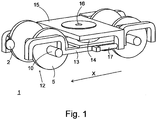
- Fig. 1 is a perspective view showing structure around wheels 5 of a train 1.
- Fig. 1 shows the structure related to characteristic portions of the embodiment in an extractive and simplified manner.
- two wheel sets 12, each including a pair of wheels 5 assembled to an axle 10 are rotatably attached to both ends of the bogie frame 13 in the longitudinal direction.
- the longitudinal direction X of the bogie frame 13 is the direction of traveling of the train 1.
- Fig. 1 shows the structure called an indirect mounting bogie, and the embodiment can also be applied to a direct mounting bogie, a bolsterless bogie, etc.
- a secondary suspension 14 that supports a bolster 15 placed thereon so as to allow vibration of the bolter 15.
- a center plate 16 is provided in the middle of the bolster 15.
- a car body of a freight car or a passenger car (not shown) is placed on the bolster 15, and the car body and the bolster 15 are connected to each other with a center pin (not shown) inserted into the center plate 16.
- a bolster anchor 17 is provided under the bolster 15. The bolster anchor 17 connects between the bolster 15 and the bogie frame 13.
- the pair of wheels 5 in one wheel set 12 have respective inner side surfaces opposed to each other, and at least one of the pair of wheels 5 is provided with a rotator 2 facing the inner side surface thereof without contact.
- the rotator 2 is supported on the bogie frame 13.
- the train 1 according to the embodiment includes the rotator 2 facing the wheel 5 without contact and a power generating unit for converting kinetic energy produced by rotation of the rotator 2 into electric energy.
- the rotator 2 includes a permanent magnet 11 that rotates around a rotation axis by the Lorentz force generated according to the rotation direction of the wheel 5.
- the rotator 2 may be disposed to face an outer side surface of the wheel 5, instead of facing the inner side surface of the wheel 5.
- the rotator 2 is hereinafter disposed to face the inner side surface of the wheel 5.
- Figs. 2 to 4 illustrate the principle of rotation of the rotator 2 caused by rotation of the wheel 5.
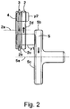
- Fig. 2 is a front view of the wheel 5 and the rotator 2
- Fig. 3 shows an arrangement of magnetic poles and directions of magnetization of the permanent magnet 11 in the rotator 2.
- the rotator 2 is disposed at a distance from the wheel 5 and configured to rotate around a rotation axis 2a thereof.
- the rotator 2 rotates in a direction according to the rotation direction of the wheel 5.
- the rotation axis 2a of the permanent magnet 11 is parallel with the rotation axis 5a of the wheel 5, and at least a part of a side surface 2d of the permanent magnet 11 that is continuous to an outer peripheral surface 2c thereof faces a side surface 5c of the wheel 5 that is continuous to an outer peripheral surface 5b thereof. More specifically, two or more of the plurality of magnetic poles 2b included in the permanent magnet 11 face the side surface 5c of the wheel 5.
- the amount of magnetic coupling between the permanent magnet 11 and the wheel 5 can be increased, and eddy currents generated in the side surface 5c of the wheel 5 can be increased.
- Examples of the wheel 5 include a wheel of a vehicle.
- the wheel 5 generates eddy currents in the side surface 5c thereof facing the permanent magnet 11.
- at least the side surface 5c of the wheel 5 needs to be formed of an electrically conductive material such as a metal.
- the eddy currents are generated in the side surface 5c of the wheel 5 by the magnetic flux from the magnetic poles 2b of the permanent magnet 11. Therefore, the distance between the side surface 2d of the permanent magnet 11 and the side surface 5c of the wheel 5 is limited to a range within which the magnetic flux from the magnetic poles 2b of the permanent magnet 11 can reach the wheel 5.
- the magnetic poles 2b of the permanent magnet 11 are magnetized in the direction toward the side surface 2d of the permanent magnet 11 or the direction opposite thereto.
- the adjacent magnetic poles 2b of the permanent magnet 11 are magnetized in opposite directions.
- the directions of magnetization of the magnetic poles 2b of the permanent magnet 11 are indicated by arrows.
- the side surface 2d of the permanent magnet 11 includes N-poles and S-poles alternating circumferentially.
- the polarities are opposite to those in the side surface 2d.
- Fig. 4 illustrates the principle of rotation of the permanent magnet 11 caused by eddy currents 6a, 6b generated in the side surface 5c of the wheel 5.
- the magnetic poles 2b arranged circumferentially in the side surface 2d of the permanent magnet 11, the magnetic poles 2b facing the side surface 5c of the wheel 5 produce magnetic flux that propagates toward the side surface 5c of the wheel 5.
- the magnetic flux from the magnetic poles 2b of the permanent magnet 11 propagates through an air gap between the side surface 2d of the permanent magnet 11 and the side surface 5c of the wheel 5.
- the direction of the eddy current 6a generated in the side surface 5c of the wheel 5 at a portion reached by the magnetic flux from an edge e1 of the N-pole at the front in the rotational direction is different from the direction of the eddy current 6b generated in the side surface 5c of the wheel 5 at a portion reached by the magnetic flux from an edge e2 of the N-pole at the rear in the rotational direction.
- the eddy current 6b generated by the magnetic flux from the edge e2 of the N-pole at the rear in the rotational direction flows in such a direction as to generate magnetic flux in an opposite direction than the magnetic flux from the N-pole.
- the eddy current 6a generated in the side surface 5c of the wheel 5 at a portion reached by the magnetic flux from the edge e1 of the N-pole at the front in the rotational direction flows in such a direction as to generate magnetic flux in the same direction as the magnetic flux from the N-pole.
- Both eddy currents 6a, 6b flow in such a direction as to hinder a change of the magnetic flux from the permanent magnet 11 caused by rotation of the wheel 5.
- the direction of the magnetic flux caused by the eddy current 6a is the same as the direction of the magnetic flux from the N-pole of the permanent magnet 11. Therefore, an attractive force acts between these magnetic fluxes.
- the direction of the magnetic flux caused by the eddy current 6b is opposite to the direction of the magnetic flux from the N-pole of the permanent magnet 11 . Therefore, a repulsive force acts between these magnetic fluxes.
- the permanent magnet 11 rotates at a surface speed smaller than the surface speed of the side surface 5c of the wheel 5 opposed thereto, so as to run after the moving surface of the side surface 5c of the wheel 5 opposed thereto.
- a coil 3 is opposed to the side surface 2e of the permanent magnet 11 on the opposite side to the side surface 2d opposed to the wheel 5.
- An air gap is provided between the coil 3 and the side surface 2e of the permanent magnet 11 opposed thereto.
- the coil 3 is fixed, and the magnetic flux from the permanent magnet 11 rotating is linked with the coil 3. Since the polarities of the plurality of magnetic poles 2b of the permanent magnet 11 arranged circumferentially alternate, the direction of the magnetic flux linked with the coil 3 alternates periodically. Therefore, in the coil 3, an induced current is generated in such a direction as to hinder a change of the magnetic flux from the permanent magnet 11, and the generated induced current can be extracted to obtain an alternating induced power. In this way, the kinetic energy of the wheel 5 can be converted into the electric energy with the coil.
- the coil serves as a power generator.
- the magnetic flux from the permanent magnet 11 is linked with the coil 3 and then propagates through the air to return to the permanent magnet 11.
- the path passed by the magnetic flux is called a magnetic path.
- the density of the magnetic flux passing the coil 3 is small, and a resultant induced current is also small.
- the magnetic flux leaks while propagating through the air or the magnetic path is altered due to an effect of an electrically conductive material in the perimeter.
- a yoke 4 is provided in the magnetic path passed by the magnetic flux linked with the coil 3.
- the yoke 4 is formed of a material having a high magnetic permeability such as iron.
- the yoke 4 is tightly attached to the surface of the coil 3 opposite to the surface thereof opposed to the permanent magnet 11 such that the magnetic flux linked with the coil 3 is guided to the yoke 4 without leakage and propagates through the yoke 4 to return to the permanent magnet 11.
- the leakage of the magnetic flux can be prevented and the magnetic efficiency can be increased.
- rotation of the wheel 5 causes the eddy currents to be generated in the surface of the wheel 5, and the magnetic flux generated by the eddy currents and the magnetic flux from the permanent magnet 11 produce the attractive force and the repulsive force acting therebetween.
- These forces constitute a force to rotate the rotator 2 in the same direction as the wheel 5. Therefore, when the wheel 5 starts rotating, the rotator 2 also starts rotating. As the wheel 5 moves or rotates faster, the force to rotate the rotator 2 becomes larger.
- the facing area in which the rotator 2 and the wheel 5 face each other is smaller than the whole area of the primary surface of the rotator 2, as shown in Fig. 4 .
- Fig. 5 shows a positional relationship between the wheel 5 and the rotator 2
- Figs. 6A and 6B are plan views from the direction P in Fig. 5 .
- the sign A denotes an ideal position of the rotator 2
- the sign B denotes the position of the rotator 2 in a first comparative example
- the sign C denotes the position of the rotator 2 in a second comparative example.
- Fig. 6A shows a positional relationship between the rotator 2 and the wheel 5 in the first comparative example
- Fig. 6B shows a positional relationship between the rotator 2 and the wheel 5 in the second comparative example.
- the wheel 5 of the train 1 includes a flange 5d on a side thereof opposed to the other wheel 5 of the same wheel set 12.
- the flange 5d reduces the possibility of derailment of the wheel 5.
- a flat surface 5e On the inner peripheral side of the flange 5d of the wheel 5, there is provided a generally flat surface (hereinafter referred to as a flat surface) 5e, and on the inner peripheral side of the flat surface 5e, there is provided an edge 5f.
- the width of the wheel 5 is smaller on the inner peripheral side of the edge 5f.
- Fig. 2 and other drawings show that the whole of the side surface of the wheel 5 opposed to the rotator 2 is the flat surface 5e. Actually, only a part of the side surface of the wheel 5 opposed to the rotator 2 is the flat surface 5e, as shown in Figs. 6A and 6B .
- the rotator 2 is separated from the flat surface 5e of the wheel 5 by a gap, and the facing area in which the rotator 2 and the flat surface 5e face each other is larger than zero and smaller than the whole area of the primary surface of the rotator 2. That is, less than the whole of the primary surface of the rotator 2 faces the flat surface 5e of the wheel 5. This is because the rotator 2 hardly rotates when the whole of the primary surface of the rotator 2 faces the flat surface 5e of the wheel 5, as described above.
- the primary surface of the rotator 2 herein refers to the whole of the side surface of the rotator 2 opposed to the wheel 5.
- the wheel 5 includes the flange 5d, the flat surface 5e, and the edge 5f on the side thereof opposed to the other wheel 5 of the same wheel set 12.
- the rotational energy generated in the rotator 2 depends on the area of the portion in which the gap between the rotator 2 and the wheel 5 is the smallest.
- the area of the portion in which the gap between the rotator 2 and the wheel 5 is the smallest is defined herein as the facing area of the rotator 2 and the wheel 5. Therefore, the facing area does not include the areas of the portion in which the rotator 2 faces the flange 5d of the wheel 5 and the portion in which the rotator 2 faces the rotation center side of the edge 5f of the wheel 5.
- the direction X refers to the horizontal direction, or the longitudinal direction of the bogie frame 13, and the direction Y refers to the vertical direction.
- the rotator 2 is positioned in the longitudinal direction X of the bogie frame 13 from the rotation center O1 of the wheel 5, or the position of the axle O1.
- the reason that the rotator 2 is disposed in the position A of Fig. 5 is as follows.
- the bogie frame 13 that supports the rotator 2 moves vertically due to the weight of the car body and the vibration caused by traveling.
- the rotator 2 is disposed in the position A of Fig. 5 , there is no possibility that the whole of the primary surface of the rotator 2 comes out of the flat surface 5e of the wheel 5 even upon vertical vibration of the bogie frame 13.
- FIGS. 6A and 6B show with a broken line the rotator 2 moved to a different position due to vertical movement of the bogie frame 13.As shown, when the bogie frame 13 is moved vertically by only several tens of millimeters, the whole of the primary surface of the rotator 2 faces the flat surface 5e of the wheel 5, or the whole of the primary surface of the rotator 2 comes out of the flat surface 5e of the wheel 5.
- the power generating performance of the rotator 2 is significantly reduced.
- Fig. 7 shows an example in which the wheel 5 has an outer diameter reduced by wheel turning.
- Fig. 8A shows the state before the bogie frame 13 moves downward.
- Fig. 8A shows an example in which the rotation center of the rotator 2 resides on the inner peripheral surface of the flat surface 5e of the wheel 5.
- the distance from the rotation center O1 of the wheel 5 to the rotation center of the rotator 2 is 400 mm, for example.
- Fig. 8B shows the state after the rotator 2 moved relatively downward by 40 mm, for example.
- the distance from the rotation center O1 of the wheel 5 to the rotation center of the rotator 2 is about 402 mm, as expressed by the Formula (2) below, with an increase of only 2 mm as compared to that in Fig. 8A .
- r 400 2 + 40 2 ⁇ 402 ⁇ mm
- the ideal position of the rotator 2 is the position A in Fig. 5 . More accurately, the ideal position of the rotator 2 is in the longitudinal direction X of the bogie frame 13 from the rotation center O1 of the wheel 5, and the facing area in which the primary surface of the rotator 2 and the flat surface 5e of the wheel 5 face each other should be larger than zero and smaller than the outer-diameter area of the primary surface of the rotator 2.
- the rotator 2 can not necessarily be disposed in the above ideal position.
- the rotator 2 may be disposed slightly off the above ideal position as long as practically satisfactory power generating performance is achieved.
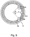
- Figs. 9 and 10 illustrate a permissible region for disposing the rotator 2.
- r1 is the radius of the inner peripheral surface of the flat surface 5e of the wheel 5
- r2 is the radius of the primary surface of the rotator 2
- ⁇ h is the range of relative downward movement of the rotator 2 due to the vertical movement of the bogie frame 13.
- Fig. 9 shows an example in which the rotator 2 is disposed within a range of ⁇ from a reference direction, which is defined as the longitudinal direction X of the bogie frame 13 from the rotation center O1 of the wheel 5.
- Fig. 10 is an enlarged view of a part of Fig. 9 .
- ⁇ is a critical angle at which the rotator 2 has moved downward by ⁇ h relative to the wheel 5 and the primary surface of the rotator 2 entirely does not face the flat surface 5e of the wheel 5.
- Fig. 10 shows an example in which the rotator 2 is disposed within a range of ⁇ from a reference direction, which is defined as the longitudinal direction X of the bogie frame 13 from the rotation center O1 of the wheel 5.
- Fig. 10 is an enlarged view of a part of Fig. 9 .
- ⁇ is a critical angle at which the rotator 2 has moved downward by ⁇ h relative to the wheel 5 and the primary surface of the rotator 2 entirely does not face the flat surface 5e
- X is the distance between the rotation center of the rotator 2 that has moved downward by ⁇ h and the reference direction
- O1 is the rotation center of the wheel 5
- O2 is the rotation center of the rotator 2 before moving downward by ⁇ h
- O3 is the rotation center of the rotator 2 after moving downward by ⁇ h
- P is the point at which the line passing through the rotation centers O2, O3 intersects the reference direction X
- Q is the point at which the line passing through the rotation center O1 of the wheel 5 and the rotation center O3 of the rotator 2 intersects the inner peripheral surface of the flat surface 5e of the wheel 5.
- the line segment O2P is expressed by Formula (5) below.
- the permissible region for disposing the rotator 2 is within the angular range of ⁇ from the reference direction X, and as indicated by Formula (6), ⁇ is determined by three parameters: the radius r1 of the inner peripheral surface of the flat surface 5e of the wheel 5, the radius r2 of the rotator 2, and the distance ⁇ h by which the rotator 2 moves downward relative to the wheel 5.
- the embodiment having a non-contact power generator installed on the train 1 is configured such that the rotator 2 opposed to the wheel 5 without contact therewith is disposed in an optimal position. More specifically, the rotator 2 is disposed within the angular range of ⁇ from the reference direction as indicated by Formula (6), the reference direction being defined as the longitudinal direction X of the bogie frame 13 from the rotation center O1 of the wheel 5.
- the reference direction being defined as the longitudinal direction X of the bogie frame 13 from the rotation center O1 of the wheel 5.
- the antilock brake control is performed using electric energy generated by the non-contact power generator installed on the train 1 as a power source.
- Fig. 11 is a block diagram schematically showing a brake control device 20 for a train.
- the brake control device 20 for a train includes a rotator 2, a power generating unit 21, an energy storage unit 22, a speed sensor 23, and an ABS (Antilock Brake System) control unit 24.
- ABS Antilock Brake System
- the rotator 2 and the power generating unit 21 may be the same as those for the first embodiment.
- the speed sensor 23 senses the rotation speed of the wheel 5.
- the power generating unit 21 converts rotational energy of the rotator 2 into electric energy with a coil, and the energy storage unit 22 stores the obtained electric energy.
- the ABS control unit 24 performs the antilock control in braking the wheel 5 based on the sensing signals from the speed sensor 23, using the electric energy according to the rotational energy of the rotator 2 as a power source. More specifically, the ABS control unit 24 transmits control signals to a brake control valve 25.
- the brake control valve 25 is opened or closed in accordance with the control signals, and thereby a brake pad 26 applies a brake to the wheel 5 intermittently.
- the electric energy generated from the rotational energy of the rotator 2 that faces the wheel 5 without contact is used for the ABS control, and therefore, the power source for the ABS control can be readily secured, and running of a long power cable is no longer necessary, resulting in reduced failures such as cable breakage.
- the rotator 2 is disposed in the position described for the first embodiment, stable power generating performance can be achieved in the power source for the ABS control that is critical to vehicles.
Landscapes
- Engineering & Computer Science (AREA)
- Mechanical Engineering (AREA)
- Transportation (AREA)
- General Engineering & Computer Science (AREA)
- Power Engineering (AREA)
- Chemical & Material Sciences (AREA)
- Combustion & Propulsion (AREA)
- Electric Propulsion And Braking For Vehicles (AREA)
- Connection Of Motors, Electrical Generators, Mechanical Devices, And The Like (AREA)
- Regulating Braking Force (AREA)
- Dynamo-Electric Clutches, Dynamo-Electric Brakes (AREA)
Abstract
Description
- The present invention relates to a train and a brake control device for a train.
- A bicycle dynamo that generates electricity without contact is disclosed in the United States Patent Application Publication No.
2014/0132155 . In the bicycle dynamo of the above publication, an outer peripheral surface of annular permanent magnet that rotates about a rotation axis extending in a direction orthogonal to a rotation axis of a bicycle wheel is spaced apart from a side surface of the wheel that is continuous with an outer peripheral surface of the wheel. - The permanent magnet in the
U.S. Patent Application Publication No. 2014/0132155 includes a plurality of magnetic poles arranged circumferentially such that adjacent magnetic poles are magnetized in opposite directions. For example, when the wheel rotates with the N pole of the permanent magnet facing the side surface of the wheel, eddy currents are generated in the side surface of the wheel in such a direction as to hinder the change of the magnetic flux from the permanent magnet. A repulsive force and attractive force between the magnetic flux generated by the eddy current and the magnetic flux from the permanent magnet cause the permanent magnet to rotate in the rotation direction of the wheel. - Thus, when a coil is wound around the permanent magnet and the magnetic flux from the permanent magnet is linked with the coil, it is possible to obtain an induced power from the coil.
- To apply the bicycle dynamo disclosed in the
U.S. Patent Application Publication No. 2014/0132155 to a power generator for a train, the permanent magnet, which has to be positioned at a distance from a wheel, may be mounted to a bogie frame of the train. However, the bogie frame of the train is located at different vertical positions depending on the weight of the body of a freight car or a passenger car placed thereon. The bogie frame also moves vertically due to the vibration caused by traveling of the train. Further, since the contact surface of the train wheel is deformed by friction with the rail, it is necessary to periodically perform maintenance work called wheel turning for scraping the contact surface. The outer diameter size of the wheel is reduced each time the wheel turning is performed, and therefore, the positional relationship between the wheel and the permanent magnet is also changed. - The vertical movement of the bogie frame and the wheel turning operation may alter the positional relationship between the permanent magnet and the wheel, failing to secure desired power generation performance.
- The present invention is intended to address the above drawback, and one object thereof is to provide a train and a brake control device for a train that secure desired power generation performance in spite of the vertical movement of the bogie frame and the wheel turning operation.
- To overcome the above drawbacks, provided is a train according to one aspect of the present invention, comprising: a wheel; a rotator disposed to face the wheel without contact and including a permanent magnet that rotates around a rotation axis by Lorentz force generated according to a rotation direction of the wheel; and a power generating unit for converting kinetic energy produced by rotation of the first rotating body into electric energy.
- It is also possible that the rotator is disposed such that a facing area of the rotator and the wheel is constant.
- It is also possible that the train further comprises a control unit for controlling an installation position of the rotator such that the facing area of the rotator and the wheel is constant.
- It is also possible that the facing area of the rotator and the wheel is smaller than an outer-diameter area of the rotator.
- It is also possible that the wheel comprises a pair of wheels connected to an axle with respective inner side surfaces opposed to each other, and at least one of the pair of wheels is provided with the rotator facing the inner side surface thereof.
- It is also possible that the train further comprises a bogie frame that rotatably supports the wheel, and the rotator is rotatably installed on the bogie frame.
- It is also possible that the rotator is rotatably installed on the bogie frame such that even upon vertical movement of the bogie frame, a facing area of the rotator and the wheel is larger than zero and smaller than an outer-diameter area of the rotator.
- It is also possible that the rotator is disposed in a longitudinal direction of the bogie frame from a rotation center of the wheel.
- It is also possible that the rotator is disposed within an angular range of ±θ from a central direction as indicated by Formula (1) below, where r1 is a radius of the wheel, r2 is a radius of the rotator, and Δh is a distance by which the rotator moves downward relative to the wheel, the central direction being defined as a longitudinal direction of the bogie frame from a rotation center of the wheel.

- According to another embodiment of the present invention, provided is a brake control unit for a train comprising: a rotator disposed to face a wheel without contact and including a permanent magnet that rotates around a rotation axis by Lorentz force generated according to a rotation direction of the wheel; a power generating unit for converting kinetic energy produced by rotation of the rotator into electric energy; a speed sensor for sensing a rotation speed of the wheel; and an antilock brake control unit for performing antilock control in braking the wheel based on a sensing signal from the speed sensor, using the electric energy obtained by the power generating unit as a power source.
- According to the present invention, desired power generation performance is secured in spite of the vertical movement of the bogie frame and the wheel turning operation.
-
-
Fig. 1 is a perspective view showing structure around wheels of a train. -
Fig. 2 is a front view of a wheel and a rotator. -
Fig. 3 shows an arrangement of magnetic poles and directions of magnetization of a permanent magnet in the rotator. -
Fig. 4 illustrates the principle of rotation of the permanent magnet caused by eddy currents generated in a side surface of the wheel. -
Fig. 5 shows a positional relationship between the wheel and the rotator. -
Fig. 6A shows a positional relationship between the rotator and the wheel in a first comparative example. -
Fig. 6B shows a positional relationship between the rotator and the wheel in a second comparative example. -
Fig. 7 shows an example in which the wheel has a reduced outer diameter. -
Fig. 8A shows the state before the bogie frame moves downward. -
Fig. 8B shows the state after the rotator moved relatively downward. -
Fig. 9 illustrates a permissible region for disposing the rotator. -
Fig. 10 is an enlarged view of a part ofFig. 9 . -
Fig. 11 is a block diagram schematically showing a brake control device for a train. - Embodiments of the present invention will be hereinafter described in detail with reference to the drawings.
Fig. 1 is a perspective view showing structure aroundwheels 5 of atrain 1.Fig. 1 shows the structure related to characteristic portions of the embodiment in an extractive and simplified manner. As shown inFig. 1 , twowheel sets 12, each including a pair ofwheels 5 assembled to anaxle 10, are rotatably attached to both ends of thebogie frame 13 in the longitudinal direction. The longitudinal direction X of thebogie frame 13 is the direction of traveling of thetrain 1. -
Fig. 1 shows the structure called an indirect mounting bogie, and the embodiment can also be applied to a direct mounting bogie, a bolsterless bogie, etc. On the top surface of thebogie frame 13 inFig. 1 , there is provided asecondary suspension 14 that supports abolster 15 placed thereon so as to allow vibration of thebolter 15. Acenter plate 16 is provided in the middle of thebolster 15. A car body of a freight car or a passenger car (not shown) is placed on thebolster 15, and the car body and thebolster 15 are connected to each other with a center pin (not shown) inserted into thecenter plate 16. Abolster anchor 17 is provided under thebolster 15. Thebolster anchor 17 connects between thebolster 15 and thebogie frame 13. - The pair of
wheels 5 in onewheel set 12 have respective inner side surfaces opposed to each other, and at least one of the pair ofwheels 5 is provided with arotator 2 facing the inner side surface thereof without contact. Therotator 2 is supported on thebogie frame 13. Thetrain 1 according to the embodiment includes therotator 2 facing thewheel 5 without contact and a power generating unit for converting kinetic energy produced by rotation of therotator 2 into electric energy. Therotator 2 includes apermanent magnet 11 that rotates around a rotation axis by the Lorentz force generated according to the rotation direction of thewheel 5. Therotator 2 may be disposed to face an outer side surface of thewheel 5, instead of facing the inner side surface of thewheel 5. By way of an example, therotator 2 is hereinafter disposed to face the inner side surface of thewheel 5. -
Figs. 2 to 4 illustrate the principle of rotation of therotator 2 caused by rotation of thewheel 5.Fig. 2 is a front view of thewheel 5 and therotator 2, andFig. 3 shows an arrangement of magnetic poles and directions of magnetization of thepermanent magnet 11 in therotator 2. - As shown in
Fig. 2 , therotator 2 is disposed at a distance from thewheel 5 and configured to rotate around arotation axis 2a thereof. Therotator 2 rotates in a direction according to the rotation direction of thewheel 5. - As shown in
Fig. 2 , therotation axis 2a of thepermanent magnet 11 is parallel with therotation axis 5a of thewheel 5, and at least a part of aside surface 2d of thepermanent magnet 11 that is continuous to an outerperipheral surface 2c thereof faces aside surface 5c of thewheel 5 that is continuous to an outerperipheral surface 5b thereof. More specifically, two or more of the plurality ofmagnetic poles 2b included in thepermanent magnet 11 face theside surface 5c of thewheel 5. Thus, as will be described later, the amount of magnetic coupling between thepermanent magnet 11 and thewheel 5 can be increased, and eddy currents generated in theside surface 5c of thewheel 5 can be increased. - Examples of the
wheel 5 include a wheel of a vehicle. Thewheel 5 generates eddy currents in theside surface 5c thereof facing thepermanent magnet 11. To generate the eddy currents, at least theside surface 5c of thewheel 5 needs to be formed of an electrically conductive material such as a metal. - In the embodiment, the eddy currents are generated in the
side surface 5c of thewheel 5 by the magnetic flux from themagnetic poles 2b of thepermanent magnet 11. Therefore, the distance between theside surface 2d of thepermanent magnet 11 and theside surface 5c of thewheel 5 is limited to a range within which the magnetic flux from themagnetic poles 2b of thepermanent magnet 11 can reach thewheel 5. - The
magnetic poles 2b of thepermanent magnet 11 are magnetized in the direction toward theside surface 2d of thepermanent magnet 11 or the direction opposite thereto. The adjacentmagnetic poles 2b of thepermanent magnet 11 are magnetized in opposite directions. InFig. 3 , the directions of magnetization of themagnetic poles 2b of thepermanent magnet 11 are indicated by arrows. As shown inFig. 3 , theside surface 2d of thepermanent magnet 11 includes N-poles and S-poles alternating circumferentially. In aside surface 2e of thepermanent magnet 11 opposite to theside surface 2d facing thewheel 5, the polarities are opposite to those in theside surface 2d. -
Fig. 4 illustrates the principle of rotation of thepermanent magnet 11 caused byeddy currents side surface 5c of thewheel 5. Among the plurality ofmagnetic poles 2b arranged circumferentially in theside surface 2d of thepermanent magnet 11, themagnetic poles 2b facing theside surface 5c of thewheel 5 produce magnetic flux that propagates toward theside surface 5c of thewheel 5. The magnetic flux from themagnetic poles 2b of thepermanent magnet 11 propagates through an air gap between theside surface 2d of thepermanent magnet 11 and theside surface 5c of thewheel 5. - When the
wheel 5 rotates, eddy currents are generated in theside surface 5c of thewheel 5 in such a direction as to hinder a change of the magnetic flux from thepermanent magnet 11. Thepermanent magnet 11 is rotated by the interaction (the repulsive force and the attractive force) between the magnetic flux generated by the eddy currents and the magnetic flux from thepermanent magnet 11. However, the surface speed of theside surface 2d of thepermanent magnet 11 is smaller than the surface speed of theside surface 5c of thewheel 5 opposed thereto. - For example, when an N-pole of the
permanent magnet 11 faces theside surface 5c of thewheel 5, the direction of the eddy current 6a generated in theside surface 5c of thewheel 5 at a portion reached by the magnetic flux from an edge e1 of the N-pole at the front in the rotational direction is different from the direction of the eddy current 6b generated in theside surface 5c of thewheel 5 at a portion reached by the magnetic flux from an edge e2 of the N-pole at the rear in the rotational direction. The eddy current 6b generated by the magnetic flux from the edge e2 of the N-pole at the rear in the rotational direction flows in such a direction as to generate magnetic flux in an opposite direction than the magnetic flux from the N-pole. On the other hand, the eddy current 6a generated in theside surface 5c of thewheel 5 at a portion reached by the magnetic flux from the edge e1 of the N-pole at the front in the rotational direction flows in such a direction as to generate magnetic flux in the same direction as the magnetic flux from the N-pole. Botheddy currents permanent magnet 11 caused by rotation of thewheel 5. - As described above, on the edge e1 side of the N-pole of the
permanent magnet 11 at the front in the rotational direction, the direction of the magnetic flux caused by theeddy current 6a is the same as the direction of the magnetic flux from the N-pole of thepermanent magnet 11. Therefore, an attractive force acts between these magnetic fluxes. On the other hand, on the edge e2 side of the N-pole of thepermanent magnet 11 at the rear in the rotational direction, the direction of the magnetic flux caused by theeddy current 6b is opposite to the direction of the magnetic flux from the N-pole of thepermanent magnet 11 . Therefore, a repulsive force acts between these magnetic fluxes. When the surface speed of theside surface 2d of thepermanent magnet 11 is smaller than the surface speed of theside surface 5c of thewheel 5 opposed thereto, the above-described relationship between thepermanent magnet 11 and theeddy currents permanent magnet 11 rotates at a surface speed smaller than the surface speed of theside surface 5c of thewheel 5 opposed thereto, so as to run after the moving surface of theside surface 5c of thewheel 5 opposed thereto. - In the example shown in
Fig. 2 , acoil 3 is opposed to theside surface 2e of thepermanent magnet 11 on the opposite side to theside surface 2d opposed to thewheel 5. An air gap is provided between thecoil 3 and theside surface 2e of thepermanent magnet 11 opposed thereto. Thecoil 3 is fixed, and the magnetic flux from thepermanent magnet 11 rotating is linked with thecoil 3. Since the polarities of the plurality ofmagnetic poles 2b of thepermanent magnet 11 arranged circumferentially alternate, the direction of the magnetic flux linked with thecoil 3 alternates periodically. Therefore, in thecoil 3, an induced current is generated in such a direction as to hinder a change of the magnetic flux from thepermanent magnet 11, and the generated induced current can be extracted to obtain an alternating induced power. In this way, the kinetic energy of thewheel 5 can be converted into the electric energy with the coil. Thus, the coil serves as a power generator. - As indicated by the arrows y1, y2 in
Fig. 2 , the magnetic flux from thepermanent magnet 11 is linked with thecoil 3 and then propagates through the air to return to thepermanent magnet 11. The path passed by the magnetic flux is called a magnetic path. When most part of a magnetic path is occupied by the air, which has a large magnetic resistance, the density of the magnetic flux passing thecoil 3 is small, and a resultant induced current is also small. In addition, it is possible that the magnetic flux leaks while propagating through the air or the magnetic path is altered due to an effect of an electrically conductive material in the perimeter. As shown inFig. 2 , it is desirable that a yoke 4 is provided in the magnetic path passed by the magnetic flux linked with thecoil 3. The yoke 4 is formed of a material having a high magnetic permeability such as iron. For example, the yoke 4 is tightly attached to the surface of thecoil 3 opposite to the surface thereof opposed to thepermanent magnet 11 such that the magnetic flux linked with thecoil 3 is guided to the yoke 4 without leakage and propagates through the yoke 4 to return to thepermanent magnet 11. Thus, the leakage of the magnetic flux can be prevented and the magnetic efficiency can be increased. - As described above, rotation of the
wheel 5 causes the eddy currents to be generated in the surface of thewheel 5, and the magnetic flux generated by the eddy currents and the magnetic flux from thepermanent magnet 11 produce the attractive force and the repulsive force acting therebetween. These forces constitute a force to rotate therotator 2 in the same direction as thewheel 5. Therefore, when thewheel 5 starts rotating, therotator 2 also starts rotating. As thewheel 5 moves or rotates faster, the force to rotate therotator 2 becomes larger. - When the whole of the primary surface of the
rotator 2 opposed to thewheel 5 overlaps the opposed surface of thewheel 5, the Lorentz forces acting on the magnetic poles of thepermanent magnet 11 in therotator 2 cancel each other, and thus therotator 2 hardly rotates, significantly reducing the power generating performance. Therefore, to stabilize the power generating performance, it is desirable that the facing area in which therotator 2 and thewheel 5 face each other is smaller than the whole area of the primary surface of therotator 2, as shown inFig. 4 . -
Fig. 5 shows a positional relationship between thewheel 5 and therotator 2, andFigs. 6A and 6B are plan views from the direction P inFig. 5 . InFig. 5 , the sign A denotes an ideal position of therotator 2, the sign B denotes the position of therotator 2 in a first comparative example, and the sign C denotes the position of therotator 2 in a second comparative example. -
Fig. 6A shows a positional relationship between therotator 2 and thewheel 5 in the first comparative example, andFig. 6B shows a positional relationship between therotator 2 and thewheel 5 in the second comparative example. As shown inFigs. 6A and 6B , thewheel 5 of thetrain 1 includes aflange 5d on a side thereof opposed to theother wheel 5 of the same wheel set 12. Theflange 5d reduces the possibility of derailment of thewheel 5. On the inner peripheral side of theflange 5d of thewheel 5, there is provided a generally flat surface (hereinafter referred to as a flat surface) 5e, and on the inner peripheral side of theflat surface 5e, there is provided anedge 5f. The width of thewheel 5 is smaller on the inner peripheral side of theedge 5f. For simplicity,Fig. 2 and other drawings show that the whole of the side surface of thewheel 5 opposed to therotator 2 is theflat surface 5e. Actually, only a part of the side surface of thewheel 5 opposed to therotator 2 is theflat surface 5e, as shown inFigs. 6A and 6B . - In the embodiment, the
rotator 2 is separated from theflat surface 5e of thewheel 5 by a gap, and the facing area in which therotator 2 and theflat surface 5e face each other is larger than zero and smaller than the whole area of the primary surface of therotator 2. That is, less than the whole of the primary surface of therotator 2 faces theflat surface 5e of thewheel 5. This is because therotator 2 hardly rotates when the whole of the primary surface of therotator 2 faces theflat surface 5e of thewheel 5, as described above. The primary surface of therotator 2 herein refers to the whole of the side surface of therotator 2 opposed to thewheel 5. - As shown in
Figs. 6A and 6B , thewheel 5 includes theflange 5d, theflat surface 5e, and theedge 5f on the side thereof opposed to theother wheel 5 of the same wheel set 12. The rotational energy generated in therotator 2 depends on the area of the portion in which the gap between therotator 2 and thewheel 5 is the smallest. The area of the portion in which the gap between therotator 2 and thewheel 5 is the smallest is defined herein as the facing area of therotator 2 and thewheel 5. Therefore, the facing area does not include the areas of the portion in which therotator 2 faces theflange 5d of thewheel 5 and the portion in which therotator 2 faces the rotation center side of theedge 5f of thewheel 5. - In
Fig. 5 , the direction X refers to the horizontal direction, or the longitudinal direction of thebogie frame 13, and the direction Y refers to the vertical direction. In the embodiment, as indicated by the position A inFig. 5 , therotator 2 is positioned in the longitudinal direction X of thebogie frame 13 from the rotation center O1 of thewheel 5, or the position of the axle O1. The reason that therotator 2 is disposed in the position A ofFig. 5 is as follows. Thebogie frame 13 that supports therotator 2 moves vertically due to the weight of the car body and the vibration caused by traveling. When therotator 2 is disposed in the position A ofFig. 5 , there is no possibility that the whole of the primary surface of therotator 2 comes out of theflat surface 5e of thewheel 5 even upon vertical vibration of thebogie frame 13. - For example, when the
rotator 2 is disposed in the position B or the position C ofFig. 5 , it is possible that the whole of the primary surface of therotator 2 faces theflat surface 5e of thewheel 5 or the whole of the primary surface of therotator 2 comes out of theflat surface 5e of thewheel 5 upon vertical movement of thebogie frame 13.Figs. 6A and 6B show with a broken line therotator 2 moved to a different position due to vertical movement of the bogie frame 13.As shown, when thebogie frame 13 is moved vertically by only several tens of millimeters, the whole of the primary surface of therotator 2 faces theflat surface 5e of thewheel 5, or the whole of the primary surface of therotator 2 comes out of theflat surface 5e of the wheel 5.When therotator 2 is in the positions shown with the broken lines inFigs. 6A and 6B , the power generating performance of therotator 2 is significantly reduced. - Since the
wheel 5 of thetrain 1 deforms by wear, thewheel 5 needs to be periodically subjected to the wheel turning operation so as to improve the quality of contact between thewheel 5 and the rail. Each time of the wheel turning operation reduces the outer diameter of thewheel 5 including theflange 5d.Fig. 7 shows an example in which thewheel 5 has an outer diameter reduced by wheel turning. When therotator 2 is positioned on the outer peripheral side of theflat surface 5e of thewheel 5, the positional relationship between theflat surface 5e of thewheel 5 and therotator 2 is altered by the wheel turning operation on thewheel 5, even taking no account of the vertical movement of thebogie frame 13. Therefore, it is possible that the whole of the primary surface of therotator 2 comes out of theflat surface 5e of thewheel 5. - When the
rotator 2 is disposed in the position A shown inFig. 5 , the proportion of overlapping of thewheel 5 and therotator 2 is not altered significantly even upon the vertical movement of thebogie frame 13 or the wheel turning operation on thewheel 5 that reduces the outer diameter of thewheel 5.Fig. 8A shows the state before thebogie frame 13 moves downward.Fig. 8A shows an example in which the rotation center of therotator 2 resides on the inner peripheral surface of theflat surface 5e of thewheel 5. The distance from the rotation center O1 of thewheel 5 to the rotation center of therotator 2 is 400 mm, for example.Fig. 8B shows the state after therotator 2 moved relatively downward by 40 mm, for example. In this state, the distance from the rotation center O1 of thewheel 5 to the rotation center of therotator 2 is about 402 mm, as expressed by the Formula (2) below, with an increase of only 2 mm as compared to that inFig. 8A .
- Therefore, when the
rotator 2 is disposed in the position A ofFig. 5 , it is less possible that the whole of the primary surface of therotator 2 faces theflat surface 5e of thewheel 5 or the whole of the primary surface of therotator 2 comes out of theflat surface 5e of thewheel 5 even upon vertical movement of thebogie frame 13, although this depends on the outer diameter of therotator 2. - Thus, the ideal position of the
rotator 2 is the position A inFig. 5 . More accurately, the ideal position of therotator 2 is in the longitudinal direction X of thebogie frame 13 from the rotation center O1 of thewheel 5, and the facing area in which the primary surface of therotator 2 and theflat surface 5e of thewheel 5 face each other should be larger than zero and smaller than the outer-diameter area of the primary surface of therotator 2. - Since the
wheel 5 of thetrain 1 is surrounded by various instruments installed on thetrain 1, it is presumable that therotator 2 can not necessarily be disposed in the above ideal position. Therotator 2 may be disposed slightly off the above ideal position as long as practically satisfactory power generating performance is achieved. -
Figs. 9 and10 illustrate a permissible region for disposing therotator 2. InFigs. 9 and10 , r1 is the radius of the inner peripheral surface of theflat surface 5e of thewheel 5, r2 is the radius of the primary surface of therotator 2, and Δh is the range of relative downward movement of therotator 2 due to the vertical movement of thebogie frame 13. -
Fig. 9 shows an example in which therotator 2 is disposed within a range of ±θ from a reference direction, which is defined as the longitudinal direction X of thebogie frame 13 from the rotation center O1 of thewheel 5.Fig. 10 is an enlarged view of a part ofFig. 9 . InFig. 10 , θ is a critical angle at which therotator 2 has moved downward by Δh relative to thewheel 5 and the primary surface of therotator 2 entirely does not face theflat surface 5e of thewheel 5. InFig. 10 , X is the distance between the rotation center of therotator 2 that has moved downward by Δh and the reference direction, O1 is the rotation center of thewheel 5, O2 is the rotation center of therotator 2 before moving downward by Δh, O3 is the rotation center of therotator 2 after moving downward by Δh, P is the point at which the line passing through the rotation centers O2, O3 intersects the reference direction X, and Q is the point at which the line passing through the rotation center O1 of thewheel 5 and the rotation center O3 of therotator 2 intersects the inner peripheral surface of theflat surface 5e of thewheel 5. - In
Fig. 10 , the triangle O2O3Q and the triangle O1O3P are similar. Therefore, the proportional expression of Formula (3) below holds.
- Making X the subject of Formula (3) results in Formula (4) below.

- The line segment O2P is expressed by Formula (5) below.

- Substituting Formula (4) for X of Formula (5) and making θ the subject results in Formula (6) below.

- Therefore, the permissible region for disposing the
rotator 2 is within the angular range of ±θ from the reference direction X, and as indicated by Formula (6), θ is determined by three parameters: the radius r1 of the inner peripheral surface of theflat surface 5e of thewheel 5, the radius r2 of therotator 2, and the distance Δh by which therotator 2 moves downward relative to thewheel 5. - When the
rotator 2 is disposed within the angular range of ±θ from the reference direction X, there is no possibility that when therotator 2 moves downward by Δh relative to thewheel 5, the whole of the primary surface of therotator 2 faces theflat surface 5e of thewheel 5 or the whole of the primary surface of therotator 2 comes out of theflat surface 5e of thewheel 5. Thus, power generating performance can be secured at a practically acceptable level. - In this way, the embodiment having a non-contact power generator installed on the
train 1 is configured such that therotator 2 opposed to thewheel 5 without contact therewith is disposed in an optimal position. More specifically, therotator 2 is disposed within the angular range of ±θ from the reference direction as indicated by Formula (6), the reference direction being defined as the longitudinal direction X of thebogie frame 13 from the rotation center O1 of thewheel 5. Thus, even upon the vertical movement of thebogie frame 13 that supports therotator 2, there is no major difference in the facing area of therotator 2 and thewheel 5, resulting in constantly stable power generating performance. - In the second embodiment, the antilock brake control is performed using electric energy generated by the non-contact power generator installed on the
train 1 as a power source. -
Fig. 11 is a block diagram schematically showing abrake control device 20 for a train. Thebrake control device 20 for a train includes arotator 2, apower generating unit 21, anenergy storage unit 22, aspeed sensor 23, and an ABS (Antilock Brake System)control unit 24. - The
rotator 2 and thepower generating unit 21 may be the same as those for the first embodiment. Thespeed sensor 23 senses the rotation speed of thewheel 5. - The
power generating unit 21 converts rotational energy of therotator 2 into electric energy with a coil, and theenergy storage unit 22 stores the obtained electric energy. - The
ABS control unit 24 performs the antilock control in braking thewheel 5 based on the sensing signals from thespeed sensor 23, using the electric energy according to the rotational energy of therotator 2 as a power source. More specifically, theABS control unit 24 transmits control signals to abrake control valve 25. Thebrake control valve 25 is opened or closed in accordance with the control signals, and thereby abrake pad 26 applies a brake to thewheel 5 intermittently. - In conventional
brake control devices 20 for a train, it was necessary to run a power cable to secure a power source. By contrast, in the embodiment, the electric energy generated by the power generator can be used mainly for the ABS control, and therefore, running of a long power cable is no longer necessary, resulting in reduced wiring in thetrain 1 and thus reduced failures such as cable breakage. - As described above, in the second embodiment, the electric energy generated from the rotational energy of the
rotator 2 that faces thewheel 5 without contact is used for the ABS control, and therefore, the power source for the ABS control can be readily secured, and running of a long power cable is no longer necessary, resulting in reduced failures such as cable breakage. In addition, since therotator 2 is disposed in the position described for the first embodiment, stable power generating performance can be achieved in the power source for the ABS control that is critical to vehicles. - Aspects of the invention are not limited to the foregoing embodiments and embrace various modifications conceivable by those skilled in the art. Advantageous effects of the invention are also not limited to those described above. That is, various additions, changes, and partial deletions are possible in a range not departing from the conceptual ideas and spirit of the present invention derived from contents defined in the claims and equivalents thereof.
-
- 1
- train
- 2
- rotator
- 3
- coil
- 4
- yoke
- 5
- wheel
- 10
- axle
- 11
- permanent magnet
- 12
- wheel set
- 13
- bogie frame
- 14
- secondary suspension
- 15
- bolster
- 16
- center plate
- 17
- bolster anchor
- 20
- brake control device for train
- 21
- power generating unit
- 22
- energy storage unit
- 23
- speed sensor
- 24
- ABS control unit
Claims (10)
- A train comprising:a wheel;a rotator disposed to face the wheel without contact and including a permanent magnet that rotates around a rotation axis by Lorentz force generated according to a rotation direction of the wheel; anda power generating unit for converting kinetic energy produced by rotation of the rotator into electric energy.
- The train of claim 1, wherein the rotator is disposed such that a facing area of the rotator and the wheel is constant.
- The train of claim 2, further comprising a control unit for controlling an installation position of the rotator such that the facing area of the rotator and the wheel is constant.
- The train of any one of claims 1 to 3, wherein the facing area of the rotator and the wheel is smaller than an outer-diameter area of the rotator.
- The train of any one of claims 1 to 4, wherein the wheel comprises a pair of wheels connected to an axle with respective inner side surfaces opposed to each other, and at least one of the pair of wheels is provided with the rotator facing the inner side surface thereof.
- The train of any one of claims 1 to 5, further comprising:a bogie frame that rotatably supports the wheel,wherein the rotator is rotatably installed on the bogie frame.
- The train of claim 6, wherein the rotator is rotatably installed on the bogie frame such that even upon vertical movement of the bogie frame, a facing area of the rotator and the wheel is larger than zero and smaller than an outer-diameter area of the rotator.
- The train of claim 6 or 7, wherein the rotator is disposed in a longitudinal direction of the bogie frame from a rotation center of the wheel.
- The train of claim 6 or 7, wherein the rotator is disposed within an angular range of ±θ from a central direction as indicated by Formula (1) below, where r1 is a radius of the wheel, r2 is a radius of the rotator, and Δh is a distance by which the rotator moves downward relative to the wheel, the central direction being defined as a longitudinal direction of the bogie frame from a rotation center of the wheel.

- A brake control device for a train, comprising:a rotator disposed to face a wheel without contact and including a permanent magnet that rotates around a rotation axis by Lorentz force generated according to a rotation direction of the wheel;a power generating unit for converting kinetic energy produced by rotation of the rotator into electric energy;a speed sensor for sensing a rotation speed of the wheel; andan antilock brake control unit for performing antilock control in braking the wheel based on a sensing signal from the speed sensor, using the electric energy obtained by the power generating unit as a power source.
Applications Claiming Priority (2)
| Application Number | Priority Date | Filing Date | Title |
|---|---|---|---|
| JP2016182046 | 2016-09-16 | ||
| PCT/JP2017/026537 WO2018051636A1 (en) | 2016-09-16 | 2017-07-21 | Train, and brake control device for train |
Publications (3)
| Publication Number | Publication Date |
|---|---|
| EP3514026A1 true EP3514026A1 (en) | 2019-07-24 |
| EP3514026A4 EP3514026A4 (en) | 2020-08-19 |
| EP3514026B1 EP3514026B1 (en) | 2023-04-05 |
Family
ID=61618763
Family Applications (1)
| Application Number | Title | Priority Date | Filing Date |
|---|---|---|---|
| EP17850542.6A Active EP3514026B1 (en) | 2016-09-16 | 2017-07-21 | Train, and brake control device for train |
Country Status (4)
| Country | Link |
|---|---|
| EP (1) | EP3514026B1 (en) |
| JP (1) | JP6685410B2 (en) |
| CN (1) | CN109715452B (en) |
| WO (1) | WO2018051636A1 (en) |
Families Citing this family (3)
| Publication number | Priority date | Publication date | Assignee | Title |
|---|---|---|---|---|
| CN112026826A (en) * | 2020-08-03 | 2020-12-04 | 浙江荷清柔性电子技术有限公司 | Railway vehicle, bogie thereof and detection device for bogie |
| CN115837842B (en) * | 2023-02-20 | 2023-05-02 | 成都西交华创科技有限公司 | Wheeled magnetic suspension traffic system, control method and application of magnetic disk system |
| NO348111B1 (en) * | 2023-10-02 | 2024-08-19 | Samkad Eng As | Vehicle tire and wheel converting kinetic energy into electrical energy |
Family Cites Families (6)
| Publication number | Priority date | Publication date | Assignee | Title |
|---|---|---|---|---|
| CN2878155Y (en) * | 2006-03-28 | 2007-03-14 | 赵全 | Magnetic braking device |
| FR2906194B1 (en) * | 2006-09-21 | 2008-12-19 | Alstom Transport Sa | RAILWAY VEHICLE EQUIPPED WITH CONTACTORS, METHOD OF CONTROLLING AND USE OF THESE CONTACTORS |
| JP2012125088A (en) * | 2010-12-10 | 2012-06-28 | Seiko Epson Corp | Electromechanical device, robot and wheel |
| RU2613188C2 (en) * | 2012-06-19 | 2017-03-15 | Амстед Рэйл Компани, Инк. | System and method for controlling operational characteristics of railway carriage |
| US20140085914A1 (en) * | 2012-09-27 | 2014-03-27 | Sunrising Eco-Friendly Technology Co., Ltd. | Contactless Generator, Component Therein and Application Thereof |
| DE102013210029A1 (en) * | 2013-05-29 | 2014-12-04 | Siemens Aktiengesellschaft | Device and method for braking a rotating element of an arrangement and arrangement with such a device |
-
2017
- 2017-07-21 CN CN201780056713.1A patent/CN109715452B/en active Active
- 2017-07-21 JP JP2018539546A patent/JP6685410B2/en active Active
- 2017-07-21 EP EP17850542.6A patent/EP3514026B1/en active Active
- 2017-07-21 WO PCT/JP2017/026537 patent/WO2018051636A1/en not_active Ceased
Also Published As
| Publication number | Publication date |
|---|---|
| CN109715452A (en) | 2019-05-03 |
| JP6685410B2 (en) | 2020-04-22 |
| CN109715452B (en) | 2021-11-16 |
| EP3514026A4 (en) | 2020-08-19 |
| EP3514026B1 (en) | 2023-04-05 |
| WO2018051636A1 (en) | 2018-03-22 |
| JPWO2018051636A1 (en) | 2019-04-18 |
Similar Documents
| Publication | Publication Date | Title |
|---|---|---|
| US8333156B2 (en) | Method and device for controlling the drive of a magnetic levitation vehicle on a magnetic levitation track | |
| EP2697893B1 (en) | Air gap control systems and methods | |
| EP3514026B1 (en) | Train, and brake control device for train | |
| US6533083B1 (en) | Eddy current braking apparatus | |
| TW467860B (en) | System for guidance of a vehicle, system for guidance and switching of a vehicle, system for conveyance, system for guidance of an object and flywheel system | |
| CN102149588B (en) | Eddy current rail brake | |
| JP3920358B2 (en) | Magnetic levitation vehicle travel system | |
| JP7007840B2 (en) | vehicle | |
| CN103223836B (en) | Electrical suspension controls device | |
| EP3309945A1 (en) | Rotary electric machine and non-contact power generator | |
| CN111942162B (en) | Magnetic suspension automobile | |
| EP1268233A4 (en) | Eddy current braking apparatus | |
| CN110232854B (en) | Electric suspension principle demonstration device | |
| WO2017216656A1 (en) | Magnetic suspension for a vehicle | |
| JP2001124550A (en) | Tilt sensor | |
| CN111092533A (en) | High-speed maglev train propelling device and high-speed maglev train | |
| CN109823192A (en) | A kind of magnetic suspension system | |
| KR20110060353A (en) | Automotive Braking System Using Eddy Current | |
| CN101870299A (en) | Motor train unit auxiliary turning combination structure and auxiliary turning method | |
| CN211075548U (en) | Circular ring type HA L BACH magnetic braking device and high-speed train | |
| JP7017180B2 (en) | Eddy current type rail brake device | |
| US7255046B2 (en) | Method and apparatus for use in guiding magnetically levitated vehicles | |
| CN103895520A (en) | Brake control method of linear induction motor for traction | |
| CN111591124B (en) | Magnetic levitation wheel and car | |
| JP2007186027A (en) | Wheel derailment prevention and braking device |
Legal Events
| Date | Code | Title | Description |
|---|---|---|---|
| STAA | Information on the status of an ep patent application or granted ep patent |
Free format text: STATUS: THE INTERNATIONAL PUBLICATION HAS BEEN MADE |
|
| PUAI | Public reference made under article 153(3) epc to a published international application that has entered the european phase |
Free format text: ORIGINAL CODE: 0009012 |
|
| STAA | Information on the status of an ep patent application or granted ep patent |
Free format text: STATUS: REQUEST FOR EXAMINATION WAS MADE |
|
| 17P | Request for examination filed |
Effective date: 20190415 |
|
| AK | Designated contracting states |
Kind code of ref document: A1 Designated state(s): AL AT BE BG CH CY CZ DE DK EE ES FI FR GB GR HR HU IE IS IT LI LT LU LV MC MK MT NL NO PL PT RO RS SE SI SK SM TR |
|
| AX | Request for extension of the european patent |
Extension state: BA ME |
|
| DAV | Request for validation of the european patent (deleted) | ||
| DAX | Request for extension of the european patent (deleted) | ||
| A4 | Supplementary search report drawn up and despatched |
Effective date: 20200722 |
|
| RIC1 | Information provided on ipc code assigned before grant |
Ipc: B61H 7/00 20060101ALI20200716BHEP Ipc: H02K 7/18 20060101ALI20200716BHEP Ipc: H02K 49/02 20060101ALI20200716BHEP Ipc: B61C 17/12 20060101ALI20200716BHEP Ipc: B60T 8/17 20060101AFI20200716BHEP |
|
| GRAP | Despatch of communication of intention to grant a patent |
Free format text: ORIGINAL CODE: EPIDOSNIGR1 |
|
| STAA | Information on the status of an ep patent application or granted ep patent |
Free format text: STATUS: GRANT OF PATENT IS INTENDED |
|
| INTG | Intention to grant announced |
Effective date: 20221025 |
|
| GRAS | Grant fee paid |
Free format text: ORIGINAL CODE: EPIDOSNIGR3 |
|
| GRAA | (expected) grant |
Free format text: ORIGINAL CODE: 0009210 |
|
| STAA | Information on the status of an ep patent application or granted ep patent |
Free format text: STATUS: THE PATENT HAS BEEN GRANTED |
|
| AK | Designated contracting states |
Kind code of ref document: B1 Designated state(s): AL AT BE BG CH CY CZ DE DK EE ES FI FR GB GR HR HU IE IS IT LI LT LU LV MC MK MT NL NO PL PT RO RS SE SI SK SM TR |
|
| REG | Reference to a national code |
Ref country code: GB Ref legal event code: FG4D |
|
| REG | Reference to a national code |
Ref country code: DE Ref legal event code: R096 Ref document number: 602017067529 Country of ref document: DE |
|
| REG | Reference to a national code |
Ref country code: CH Ref legal event code: EP |
|
| REG | Reference to a national code |
Ref country code: AT Ref legal event code: REF Ref document number: 1558020 Country of ref document: AT Kind code of ref document: T Effective date: 20230415 |
|
| REG | Reference to a national code |
Ref country code: IE Ref legal event code: FG4D |
|
| P01 | Opt-out of the competence of the unified patent court (upc) registered |
Effective date: 20230523 |
|
| REG | Reference to a national code |
Ref country code: LT Ref legal event code: MG9D |
|
| REG | Reference to a national code |
Ref country code: NL Ref legal event code: MP Effective date: 20230405 |
|
| REG | Reference to a national code |
Ref country code: AT Ref legal event code: MK05 Ref document number: 1558020 Country of ref document: AT Kind code of ref document: T Effective date: 20230405 |
|
| PG25 | Lapsed in a contracting state [announced via postgrant information from national office to epo] |
Ref country code: NL Free format text: LAPSE BECAUSE OF FAILURE TO SUBMIT A TRANSLATION OF THE DESCRIPTION OR TO PAY THE FEE WITHIN THE PRESCRIBED TIME-LIMIT Effective date: 20230405 |
|
| PG25 | Lapsed in a contracting state [announced via postgrant information from national office to epo] |
Ref country code: SE Free format text: LAPSE BECAUSE OF FAILURE TO SUBMIT A TRANSLATION OF THE DESCRIPTION OR TO PAY THE FEE WITHIN THE PRESCRIBED TIME-LIMIT Effective date: 20230405 Ref country code: PT Free format text: LAPSE BECAUSE OF FAILURE TO SUBMIT A TRANSLATION OF THE DESCRIPTION OR TO PAY THE FEE WITHIN THE PRESCRIBED TIME-LIMIT Effective date: 20230807 Ref country code: NO Free format text: LAPSE BECAUSE OF FAILURE TO SUBMIT A TRANSLATION OF THE DESCRIPTION OR TO PAY THE FEE WITHIN THE PRESCRIBED TIME-LIMIT Effective date: 20230705 Ref country code: ES Free format text: LAPSE BECAUSE OF FAILURE TO SUBMIT A TRANSLATION OF THE DESCRIPTION OR TO PAY THE FEE WITHIN THE PRESCRIBED TIME-LIMIT Effective date: 20230405 Ref country code: AT Free format text: LAPSE BECAUSE OF FAILURE TO SUBMIT A TRANSLATION OF THE DESCRIPTION OR TO PAY THE FEE WITHIN THE PRESCRIBED TIME-LIMIT Effective date: 20230405 |
|
| PG25 | Lapsed in a contracting state [announced via postgrant information from national office to epo] |
Ref country code: RS Free format text: LAPSE BECAUSE OF FAILURE TO SUBMIT A TRANSLATION OF THE DESCRIPTION OR TO PAY THE FEE WITHIN THE PRESCRIBED TIME-LIMIT Effective date: 20230405 Ref country code: PL Free format text: LAPSE BECAUSE OF FAILURE TO SUBMIT A TRANSLATION OF THE DESCRIPTION OR TO PAY THE FEE WITHIN THE PRESCRIBED TIME-LIMIT Effective date: 20230405 Ref country code: LV Free format text: LAPSE BECAUSE OF FAILURE TO SUBMIT A TRANSLATION OF THE DESCRIPTION OR TO PAY THE FEE WITHIN THE PRESCRIBED TIME-LIMIT Effective date: 20230405 Ref country code: LT Free format text: LAPSE BECAUSE OF FAILURE TO SUBMIT A TRANSLATION OF THE DESCRIPTION OR TO PAY THE FEE WITHIN THE PRESCRIBED TIME-LIMIT Effective date: 20230405 Ref country code: IS Free format text: LAPSE BECAUSE OF FAILURE TO SUBMIT A TRANSLATION OF THE DESCRIPTION OR TO PAY THE FEE WITHIN THE PRESCRIBED TIME-LIMIT Effective date: 20230805 Ref country code: HR Free format text: LAPSE BECAUSE OF FAILURE TO SUBMIT A TRANSLATION OF THE DESCRIPTION OR TO PAY THE FEE WITHIN THE PRESCRIBED TIME-LIMIT Effective date: 20230405 Ref country code: GR Free format text: LAPSE BECAUSE OF FAILURE TO SUBMIT A TRANSLATION OF THE DESCRIPTION OR TO PAY THE FEE WITHIN THE PRESCRIBED TIME-LIMIT Effective date: 20230706 Ref country code: AL Free format text: LAPSE BECAUSE OF FAILURE TO SUBMIT A TRANSLATION OF THE DESCRIPTION OR TO PAY THE FEE WITHIN THE PRESCRIBED TIME-LIMIT Effective date: 20230405 |
|
| PG25 | Lapsed in a contracting state [announced via postgrant information from national office to epo] |
Ref country code: FI Free format text: LAPSE BECAUSE OF FAILURE TO SUBMIT A TRANSLATION OF THE DESCRIPTION OR TO PAY THE FEE WITHIN THE PRESCRIBED TIME-LIMIT Effective date: 20230405 |
|
| REG | Reference to a national code |
Ref country code: DE Ref legal event code: R097 Ref document number: 602017067529 Country of ref document: DE |
|
| PG25 | Lapsed in a contracting state [announced via postgrant information from national office to epo] |
Ref country code: SK Free format text: LAPSE BECAUSE OF FAILURE TO SUBMIT A TRANSLATION OF THE DESCRIPTION OR TO PAY THE FEE WITHIN THE PRESCRIBED TIME-LIMIT Effective date: 20230405 |
|
| PG25 | Lapsed in a contracting state [announced via postgrant information from national office to epo] |
Ref country code: SM Free format text: LAPSE BECAUSE OF FAILURE TO SUBMIT A TRANSLATION OF THE DESCRIPTION OR TO PAY THE FEE WITHIN THE PRESCRIBED TIME-LIMIT Effective date: 20230405 Ref country code: SK Free format text: LAPSE BECAUSE OF FAILURE TO SUBMIT A TRANSLATION OF THE DESCRIPTION OR TO PAY THE FEE WITHIN THE PRESCRIBED TIME-LIMIT Effective date: 20230405 Ref country code: RO Free format text: LAPSE BECAUSE OF FAILURE TO SUBMIT A TRANSLATION OF THE DESCRIPTION OR TO PAY THE FEE WITHIN THE PRESCRIBED TIME-LIMIT Effective date: 20230405 Ref country code: EE Free format text: LAPSE BECAUSE OF FAILURE TO SUBMIT A TRANSLATION OF THE DESCRIPTION OR TO PAY THE FEE WITHIN THE PRESCRIBED TIME-LIMIT Effective date: 20230405 Ref country code: DK Free format text: LAPSE BECAUSE OF FAILURE TO SUBMIT A TRANSLATION OF THE DESCRIPTION OR TO PAY THE FEE WITHIN THE PRESCRIBED TIME-LIMIT Effective date: 20230405 Ref country code: CZ Free format text: LAPSE BECAUSE OF FAILURE TO SUBMIT A TRANSLATION OF THE DESCRIPTION OR TO PAY THE FEE WITHIN THE PRESCRIBED TIME-LIMIT Effective date: 20230405 |
|
| PLBE | No opposition filed within time limit |
Free format text: ORIGINAL CODE: 0009261 |
|
| STAA | Information on the status of an ep patent application or granted ep patent |
Free format text: STATUS: NO OPPOSITION FILED WITHIN TIME LIMIT |
|
| PG25 | Lapsed in a contracting state [announced via postgrant information from national office to epo] |
Ref country code: MC Free format text: LAPSE BECAUSE OF FAILURE TO SUBMIT A TRANSLATION OF THE DESCRIPTION OR TO PAY THE FEE WITHIN THE PRESCRIBED TIME-LIMIT Effective date: 20230405 |
|
| PG25 | Lapsed in a contracting state [announced via postgrant information from national office to epo] |
Ref country code: MC Free format text: LAPSE BECAUSE OF FAILURE TO SUBMIT A TRANSLATION OF THE DESCRIPTION OR TO PAY THE FEE WITHIN THE PRESCRIBED TIME-LIMIT Effective date: 20230405 |
|
| REG | Reference to a national code |
Ref country code: CH Ref legal event code: PL |
|
| 26N | No opposition filed |
Effective date: 20240108 |
|
| REG | Reference to a national code |
Ref country code: BE Ref legal event code: MM Effective date: 20230731 |
|
| PG25 | Lapsed in a contracting state [announced via postgrant information from national office to epo] |
Ref country code: LU Free format text: LAPSE BECAUSE OF NON-PAYMENT OF DUE FEES Effective date: 20230721 |
|
| PG25 | Lapsed in a contracting state [announced via postgrant information from national office to epo] |
Ref country code: LU Free format text: LAPSE BECAUSE OF NON-PAYMENT OF DUE FEES Effective date: 20230721 |
|
| REG | Reference to a national code |
Ref country code: IE Ref legal event code: MM4A |
|
| PG25 | Lapsed in a contracting state [announced via postgrant information from national office to epo] |
Ref country code: CH Free format text: LAPSE BECAUSE OF NON-PAYMENT OF DUE FEES Effective date: 20230731 |
|
| PG25 | Lapsed in a contracting state [announced via postgrant information from national office to epo] |
Ref country code: SI Free format text: LAPSE BECAUSE OF FAILURE TO SUBMIT A TRANSLATION OF THE DESCRIPTION OR TO PAY THE FEE WITHIN THE PRESCRIBED TIME-LIMIT Effective date: 20230405 |
|
| PG25 | Lapsed in a contracting state [announced via postgrant information from national office to epo] |
Ref country code: SI Free format text: LAPSE BECAUSE OF FAILURE TO SUBMIT A TRANSLATION OF THE DESCRIPTION OR TO PAY THE FEE WITHIN THE PRESCRIBED TIME-LIMIT Effective date: 20230405 Ref country code: IT Free format text: LAPSE BECAUSE OF FAILURE TO SUBMIT A TRANSLATION OF THE DESCRIPTION OR TO PAY THE FEE WITHIN THE PRESCRIBED TIME-LIMIT Effective date: 20230405 Ref country code: BE Free format text: LAPSE BECAUSE OF NON-PAYMENT OF DUE FEES Effective date: 20230731 |
|
| PG25 | Lapsed in a contracting state [announced via postgrant information from national office to epo] |
Ref country code: IE Free format text: LAPSE BECAUSE OF NON-PAYMENT OF DUE FEES Effective date: 20230721 |
|
| PG25 | Lapsed in a contracting state [announced via postgrant information from national office to epo] |
Ref country code: IE Free format text: LAPSE BECAUSE OF NON-PAYMENT OF DUE FEES Effective date: 20230721 |
|
| PG25 | Lapsed in a contracting state [announced via postgrant information from national office to epo] |
Ref country code: BG Free format text: LAPSE BECAUSE OF FAILURE TO SUBMIT A TRANSLATION OF THE DESCRIPTION OR TO PAY THE FEE WITHIN THE PRESCRIBED TIME-LIMIT Effective date: 20230405 |
|
| PG25 | Lapsed in a contracting state [announced via postgrant information from national office to epo] |
Ref country code: BG Free format text: LAPSE BECAUSE OF FAILURE TO SUBMIT A TRANSLATION OF THE DESCRIPTION OR TO PAY THE FEE WITHIN THE PRESCRIBED TIME-LIMIT Effective date: 20230405 |
|
| PG25 | Lapsed in a contracting state [announced via postgrant information from national office to epo] |
Ref country code: CY Free format text: LAPSE BECAUSE OF FAILURE TO SUBMIT A TRANSLATION OF THE DESCRIPTION OR TO PAY THE FEE WITHIN THE PRESCRIBED TIME-LIMIT; INVALID AB INITIO Effective date: 20170721 |
|
| PG25 | Lapsed in a contracting state [announced via postgrant information from national office to epo] |
Ref country code: HU Free format text: LAPSE BECAUSE OF FAILURE TO SUBMIT A TRANSLATION OF THE DESCRIPTION OR TO PAY THE FEE WITHIN THE PRESCRIBED TIME-LIMIT; INVALID AB INITIO Effective date: 20170721 |
|
| PGFP | Annual fee paid to national office [announced via postgrant information from national office to epo] |
Ref country code: DE Payment date: 20250722 Year of fee payment: 9 |
|
| PGFP | Annual fee paid to national office [announced via postgrant information from national office to epo] |
Ref country code: GB Payment date: 20250722 Year of fee payment: 9 |
|
| PGFP | Annual fee paid to national office [announced via postgrant information from national office to epo] |
Ref country code: FR Payment date: 20250725 Year of fee payment: 9 |
|
| PG25 | Lapsed in a contracting state [announced via postgrant information from national office to epo] |
Ref country code: TR Free format text: LAPSE BECAUSE OF FAILURE TO SUBMIT A TRANSLATION OF THE DESCRIPTION OR TO PAY THE FEE WITHIN THE PRESCRIBED TIME-LIMIT Effective date: 20230405 |