EP3513976B1 - Methods and apparatuses for authorized use and refill of a printer cartridge - Google Patents
Methods and apparatuses for authorized use and refill of a printer cartridge Download PDFInfo
- Publication number
- EP3513976B1 EP3513976B1 EP19158000.0A EP19158000A EP3513976B1 EP 3513976 B1 EP3513976 B1 EP 3513976B1 EP 19158000 A EP19158000 A EP 19158000A EP 3513976 B1 EP3513976 B1 EP 3513976B1
- Authority
- EP
- European Patent Office
- Prior art keywords
- cartridge
- chip
- message
- nonce
- refill
- Prior art date
- Legal status (The legal status is an assumption and is not a legal conclusion. Google has not performed a legal analysis and makes no representation as to the accuracy of the status listed.)
- Active
Links
Images


Classifications
-
- B—PERFORMING OPERATIONS; TRANSPORTING
- B41—PRINTING; LINING MACHINES; TYPEWRITERS; STAMPS
- B41J—TYPEWRITERS; SELECTIVE PRINTING MECHANISMS, i.e. MECHANISMS PRINTING OTHERWISE THAN FROM A FORME; CORRECTION OF TYPOGRAPHICAL ERRORS
- B41J2/00—Typewriters or selective printing mechanisms characterised by the printing or marking process for which they are designed
- B41J2/005—Typewriters or selective printing mechanisms characterised by the printing or marking process for which they are designed characterised by bringing liquid or particles selectively into contact with a printing material
- B41J2/01—Ink jet
- B41J2/17—Ink jet characterised by ink handling
- B41J2/175—Ink supply systems ; Circuit parts therefor
- B41J2/17503—Ink cartridges
- B41J2/17543—Cartridge presence detection or type identification
- B41J2/17546—Cartridge presence detection or type identification electronically
-
- B—PERFORMING OPERATIONS; TRANSPORTING
- B41—PRINTING; LINING MACHINES; TYPEWRITERS; STAMPS
- B41J—TYPEWRITERS; SELECTIVE PRINTING MECHANISMS, i.e. MECHANISMS PRINTING OTHERWISE THAN FROM A FORME; CORRECTION OF TYPOGRAPHICAL ERRORS
- B41J2/00—Typewriters or selective printing mechanisms characterised by the printing or marking process for which they are designed
- B41J2/005—Typewriters or selective printing mechanisms characterised by the printing or marking process for which they are designed characterised by bringing liquid or particles selectively into contact with a printing material
- B41J2/01—Ink jet
- B41J2/17—Ink jet characterised by ink handling
- B41J2/175—Ink supply systems ; Circuit parts therefor
- B41J2/17566—Ink level or ink residue control
Definitions
- the systems, methods and apparatuses described herein relate to prevention of unauthorized cartridges or unauthorized refill of authorized cartridges.
- printers and copy machines have also become prevalent among households.
- Printers and copy machines use toner or ink very quickly.
- the cartridges typically need to be replaced or refilled very often.
- the manufacturers of printers and copy machines often rely on the sale of replacement cartridges to generate a healthy revenue.
- the strong demand for cartridges has created a big market for unauthorized cartridges and/or unauthorized refills. These unauthorized cartridges and unauthorized refills adversely financially impact the manufacturers of printers and copy machines.
- US 2004/0049468 A1 relates to a consumable authentication method for validating the existence of an untrusted chip. A random number is encrypted using a first key and sent to an untrusted chip.
- US 2009/0319802 A1 relates to a method of manufacturing a series of integrated circuits having related functionality, the method including the steps of: (a) determining an identifier; (b) permanently storing the identifier on one of the integrated circuits; (c) repeating steps (a) and (b) for each integrated circuit in the series; and wherein the identifiers for the series are determined in such a way that knowing the identifier of one of the integrated circuits does not improve the ability of an attacker to determine the identifier of any of the other integrated circuits.
- the present disclosure comprises methods and apparatuses for prevention of using unauthorized cartridges or unauthorized refill of authorized cartridges. While the present invention is described and explained in the context of refill of an ink or toner printer or copier cartridge, it is to be understood that it is not so limited and may be applicable to any systems, methods and apparatuses directed to preventing unauthorized use and/or refill on an apparatus. Moreover, while the specification generally refers to toner cartridges, it is to be understood that the concepts discussed herein apply to any apparatuses that dispense material (e.g., ink, toner) to print text and/or graphics on paper.
- material e.g., ink, toner
- a cartridge is provided with a chip according to claim 1.
- a method not according to the invention for performing a print job using an authorized cartridge may be provided.
- the method may comprise generating an initial operation input value at a printing device, sending the initial operation input value to a cartridge, receiving a response from the cartridge, verifying the response containing a calculation result that matches an expected value (which also may be referred to as a verification value) and the response being received within a pre-defined time threshold, and performing the print job when the verification is successful.
- the initial operation input value may be a nonce generated by the printing device.
- the initial operation input value may be a number derived from the nonce using a pre-defined computation function.
- FIG. 1 shows a block diagram of an exemplary system 100 for using an exemplary cartridge 110 according to the present disclosure.
- the exemplary cartridge 110 may be used by an exemplary printing device 140 to print documents.
- the exemplary cartridge 110 may comprise a chip 115.
- the chip 115 may comprise a non-volatile memory 120, a random number generator (RNG) 122, a key 124, a signature verification module 126 and a computation module 128.
- the cartridge 110 may also include a cartridge identifier, for example, a cartridge serial number, that can be used to uniquely identify the cartridge.
- the cartridge identifier may be stored in the non-volatile memory 120.
- the chip 115 may be tamper-resistant so that the non-volatile memory 120 and other components of the chip 115 could not be easily modified.
- the printing device 140 may comprise a RNG 142 and a computation module 144.
- Each of the RNGs 122 and 142 may be a hardware-based (such as, for example, a thermal-noise based, oscillator-jitter-based, or Zener noise-based generator), or software-based (such as, for example, linear congruential generator, Mersenne Twister generator, or cryptographic generator such as Blum-Blum-Shub, Yarrow or Fortuna) random number generator.
- the RNGs 122 and 142 may be used to generate nonces for secure communication with other devices (e.g., between the cartridge 110 and the printing device 140, between the cartridge 110 and a refill device as shown in FIG. 2 , etc.).
- the RNG 122 or 142 may be software based, its initial state may be set to different values for different chips at the time of manufacture (or prior to first use). For example, in some embodiments it may be performed during standard chip testing procedures (such as IEEE 1149.1-based testing). Additionally, the chip 115 may collect and supply the RNG 122 or 142 with additional randomness obtained from various data, states and/or events. By way of example and not limitation, a subset of the bits constituting commands sent to the chip 115, the temperature of the chip 115 at a particular point in time, and/or the number of clock counts of a counter (not shown) between certain events may be obtained and supplied to the RNG as sources of randomness.
- the chip 115 may process a command to add randomness.
- a command may have as a parameter, for example, comprising an externally generated random number.
- the chip 115 may use the random number received to update the current state of the RNG.
- the exemplary cartridge 110 and the printing device 140 may be coupled by an interface 130.
- the interface 130 may be a wired connection (such as serial, parallel, Ethernet, or USB), or a wireless connection (such as Bluetooth, near field communications, infrared, or various flavors of IEEE 802.11), and/or any suitable custom connection.
- the interface 130 may be a Serial Peripheral Interface (SPI) Bus.
- SPI Serial Peripheral Interface
- the non-volatile memory 120 may store a number representing the amount of toner in the cartridge 110.
- the initial value of the number representing the amount of toner may be set at the time the toner cartridge 110 is filled for the first time.
- an initial value representing the amount of toner in the cartridge may be programmed into or stored in the memory 120 at the time that the chip 115 or cartridge 110 is manufactured. For example, in some embodiments it may be performed during standard chip testing procedures (such as IEEE 1149.1-based testing). In such an embodiment, the initial value need not be set at the same time the cartridge is filled for the first time but may be interpreted as corresponding to the amount of toner in a fully filled cartridge.
- the cartridge 110 can only be filled once and cannot be refilled.
- the chip 115 may have an on-chip fuse (or anti-fuse) which is permanently and irreversibly programmed after the initial value representing the amount of toner is written (and/or command(s) to add randomness is processed). When the fuse or anti-fuse is permanently and irreversibly programmed, the chip 115 may stop responding to requests to write the initial amount of toner and/or to commands to add randomness.
- the initial state of the memory 120 after manufacture and prior to any initialization may be interpreted as corresponding to the amount of toner in a fully filled cartridge.
- this state is the same for all the memories 120 incorporated into the chips 115.
- all of the bits of the EEPROM or flash memory may have the same value (for example, all the bits may be set to 1).
- the default state e.g., when all the bits are set to 1 may be interpreted as corresponding to the amount of toner in a fully filled cartridge.
- the key 124 may be a public encryption key of a public/private key pair.
- the key 124 may be an Elliptic Curve Cryptography (ECC) public key (e.g., ECC-224), or an RSA public key.
- ECC Elliptic Curve Cryptography
- the signature verification module 126 may implement a signature verification algorithm based on the public key 124.
- the signature verification module 126 may implement a secure hash algorithm (e.g., SHA-0, SHA-1, or SHA-2) and/or ECC verification.
- the computation module 128 may be a dedicated computation module that is configured to perform one or more pre-defined calculation operations and to be able to perform the pre-defined operations very quickly.
- the computation engine 128 may be implemented in an Application-Specific Integrated Circuit (ASIC) favoring speed of processing and may be much faster than a corresponding field programmable gate arrays (FPGAs) implementation.
- ASIC Application-Specific Integrated Circuit
- FPGAs field programmable gate arrays
- the ASIC implementation may also be much faster than software emulation using the combination of general purpose CPUs and/or graphical processing units (GPUs).
- the computation module 128 may be configured for computing recursively a hash value from an initial input value received by the computation module 128.
- the hash function may be any hash function such as, for example, SHA-1, or SHA-256.
- the hash function H may be pre-defined (e.g., by chip manufacturers or cartridge manufacturers), while the number N and initial value V 0 may be provided at runtime (e.g., during refill or print operations).
- the computation module 144 may be configured to perform the same calculation operations as the computation engine 128 and may be used by the printing device 140 to verify a calculation result returned by the cartridge 110 during an operation.
- the computation speed of the computation module 144 does not need to be as fast as the computation module 128.
- the computation module 144 may be implemented in hardware (e.g., ASIC or FPGA) or software (e.g., software emulator running on a general purpose CPU and/or GPU).
- identical chips 115 may be used in a plurality of cartridges (e.g., in a set of cartridges manufactured in a batch) to reduce manufacturing cost.
- the chips 115 may be changed often to ensure better security.
- only the public keys 124 may be changed periodically but other components of the chips 115 may be identical between different batches. With respect to any of the embodiments, it may be advantageous to mix chips from different batches before distribution so that cartridges sold in the same geographic area come from different batches.
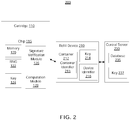
- FIG. 2 is a block diagram of an exemplary system 200 for refilling the exemplary cartridge 110 according to the present disclosure.
- the refilling system 200 may comprise a refill device 210 and a central server 230 in addition to the exemplary cartridge 110 (which is the same as that of the system 100).
- the refill device 210 may comprise a container 212 of toner for cartridge refill.
- the container 212 may have a container identifier 213 (e.g., a serial number) that can uniquely identify the container 212.
- the refill device 210 may also comprise a key 214 and a device identifier 216.
- the key 214 may be a private key of a public/private key pair.
- the private key may be, for example, an RSA or ECC private key, which may be used for signing data sent from the refill device 210.
- the device identifier 216 may be a unique identifier for the refill device 210 (e.g., a device serial number) to uniquely identify the refill device 210.
- the refill device 210 may also store a copy of the public keys 124 of the cartridge 110.
- the central server 230 may have a database 235 and a key 237.
- the database 235 may store information about authorized refill devices.
- the stored information may include, for example, the device identifiers (e.g., the device identifier 216), public keys that correspond to the private key of the refill devices (e.g., the public key corresponding to the private key 214), information about current operators and/or owners of the refill devices, container identifiers (e.g., the container identifier 213) of each container acquired for each refill device, and the amount of toner remaining in each container.
- the public keys 214 may serve as unique identifiers for respective refill devices 210.
- the key 237 may be the private key that corresponds to the public key 124 stored at the cartridge 110 (and at the refill device 210 in some embodiments). In some embodiments, the key 237 may be stored in a database (e.g., the database 235 or another database accessible by the central server 230).
- a database e.g., the database 235 or another database accessible by the central server 230.
- the cartridge 110 may communicate with the refill device 210 for refill operations and the refill devices 210 may communicate with the central server 230.
- the communication connection between the refill device 210 and cartridge 110 may be a wired connection (such as serial, parallel, Ethernet, and USB), or a wireless connection (such as Bluetooth, near field communications, infrared, various flavors of IEEE 802.11), and/or any suitable custom connection.
- the communication connection between the refill device 210 and the central server 230 may include any suitable connections, for example, wired and/or wireless connections, and may include the Internet.
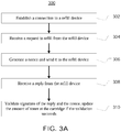
- FIG. 3A is a flow diagram of an exemplary process 300 for refilling an exemplary cartridge according to the present disclosure.
- the cartridge 110 may establish a communication/data connection to the refill device 210.
- the cartridge chip 115 may receive a request from the refill device 210 to refill the cartridge 110.
- the cartridge chip 115 may generate a request to the refill device 210 to refill the cartridge 110.
- the request whether sent or received may, for example, initiate setting an amount of toner to the cartridge chip 115.
- the cartridge chip 115 may generate a nonce using the RNG 122, and send the generated nonce to the refill device 210.
- the nonce may be of any length and in one embodiment may be 128 bits.
- the cartridge identifier may also be sent along with the nonce to the refill device 210.
- the cartridge chip 115 may receive a reply from the refill device 210.
- the reply may be generated by a central server such as the central server 230 and forwarded to the cartridge 110 by the refill device 210.
- the cartridge chip 115 may validate the signature of the reply using the key 124 (e.g., by using the signature validation module 126) and validate that the received nonce (in the reply) is the same as the nonce generated at block 306.
- the cartridge chip 115 may also ensure that the time period from sending the nonce until receiving the reply may be within a pre-defined threshold.
- the pre-defined threshold may be any amount of time and in one embodiment may be 15 seconds. If all validations are successful, the chip 115 may write the amount of toner (e.g., the amount of toner requested in a request for refill sent by the refill device to the central server) into the non-volatile memory 120.
- FIG. 3B is a flow diagram of an exemplary process 315 for an exemplary refill device to refill an exemplary cartridge according to the present disclosure.
- the refill device 210 may establish a communication/data connection to a cartridge such as the cartridge 110.
- the refill device 210 may generate a request to refill the cartridge and send the request to the cartridge.
- the refill device may receive from the cartridge a request to refill the cartridge. The request whether sent or received may, for example, initiate setting an amount of toner to the cartridge chip 115.
- the refill device 210 may receive a nonce from the cartridge 110. In one non-limiting embodiment, the refill device 210 may also receive the cartridge identifier if the cartridge sends its cartridge identifier.
- the refill device 210 may generate a request for refill and send it to an authorization server (e.g., the central server 230).
- FIG. 3D shows an exemplary data structure for a request for refill 360 according to the present disclosure.
- the request for refill 360 may include a nonce 362, toner requested 364, a container identifier 366, a refill device identifier 368, and an amount of toner requested 370.
- the nonce 362 may be the nonce received from the cartridge 110 (e.g., the nonce generated at block 315 at the chip 115).
- the toner requested 364 may include information about the particular type of toner requested, for example, "blue toner type BT-198.”
- the container identifier 366 may be the identifier of the container that the refill device may use to dispense the toner from (e.g., the container identifier 213 of the container 212).
- the refill device identifier 368 may be the device identifier of the refill device submitting the request for refill (e.g., the device identifier 216).
- the amount of toner 370 may be a number representing the amount of toner that needs to be dispensed into the cartridge to be refilled.
- the request for refill 360 may be signed by the refill device 210 using the refill device's private key (e.g., the key 214). The signature may be sent along with the request for refill to the central server 230.
- the cartridge identifier received from the cartridge may also be included in the request for refill 360.
- the refill device 210 may receive a reply from the authorization server (e.g., the central server 230) and determine whether the reply is an authorization or denial of authorization. If the reply is a denial of authorization, the process 315 may be aborted at block 334. For example, the refill device 210 may report an error message to an operator of the device and end the refill process 315. If the reply is an authorization, the process 315 may proceed to block 332, at which the refill device 210 may forward the reply to the cartridge 110 and also perform the physical act of refilling the cartridge.
- the reply may be encrypted by the authorization server, for example, using the authorization server's private key.
- the refill device 210 may use one or more of the following ways to determine whether the reply is an authorization.
- the refill device 210 may have a copy of the public key 124 that corresponds to the authorization server's private key and may use its copy of the public key 124 to decrypt the reply.
- the authorization server may send an additional message with the reply that indicates that the request has been granted.
- the additional message may be signed by the refill device 210's public key (taken from the database 235).
- the reply to be forwarded to the cartridge 110 may be a part of a larger message sent to the refill device 210.
- the larger message may be signed by a public key of the refill device 210.
- the refill device 210 may receive all data over a secure connection (e.g., SSL), and the received data may contain both a message for the cartridge 110 and the permission for refill.
- SSL secure connection
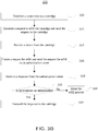
- FIG. 3C is a flow diagram of an exemplary process 340 for authorizing a refill according to the present disclosure.
- the central server 230 may receive a request for refill (e.g., a request comprising or including the request for refill 360) sent from the refill device 210.
- the process 340 may decide whether the request for refill should be authorized.
- the central server 230 may verify that the refill device 210 (identified by the device identifier 368 in the request) may be an authorized refill device and associated with an authorized owner or operator, that the refill device 210 may indeed have an authorized toner container (identified by the container identifier 366 in the request), and that the authorized toner container has a sufficient amount of toner to satisfy the amount of toner requested.
- the central server 230 may query its database 235 using the device identifier 368 and container identifier 366 for the verification.
- the central server 230 may have access to a database storing cartridge identifiers for authorized cartridges. In this case, the central server 230 may also verify that the cartridge is an authorized cartridge by searching its database for authorized cartridges.
- the central server 230 may take into account any potential physical inaccuracies in determining whether there is a sufficient amount of toner in the container. For example, the central server 230 may assume that the container 212 may actually have slightly more toner than the information stored in the database 235 indicates. In some embodiments, the central server 230 may store a public key corresponding to the private key 214 of the refill device 210. In these embodiments, if the request for refill 360 is signed by the private key 214, the central server 230 may use the public key to verify the signature. The public key may be stored in the database 235 or in another database.
- the process 340 may proceed to block 346, at which the central server 230 may generate a reply to authorize the refill and send the authorization to the refill device 210. If any one of the verifications fails, the process 340 may proceed to block 348, at which the central server 230 may generate a reply to deny the refill.
- the reply may include the nonce 362 received in the request and may be signed by the private key 237 stored at the central server 230. Also, in some embodiments, the reply may additionally be encrypted using the private key 237 (so that only the cartridge chip 115 may recognize the authorization by decrypting the reply using the key 124, which may be the public key corresponding to the key 237 as described above).
- each chip 115 may have a globally unique private key and a chip ID.
- the private key may have a corresponding public key stored at the central server 230 or stored at a third party but accessible by the central server 230.
- the chip 115 may use this private key to sign a request for refill 360 or sign just part of such a request (e.g., only signing the nonce 362).
- the signature and the chip ID may be sent, together with the request for refill, to the server 230.
- the central server 230 may keep records for all refill activities associated with each chip ID.
- the server 230 using the chip ID, may obtain the public key corresponding to the private key and verify the signature. If the signature verification fails, the request for refill may be denied. If the signature verification passes, this refill activity may be added to the database for the chip ID.
- records of the refill activities associated with a requesting chip may be analyzed. For example, if the historical information shows that a particular chip signs too many requests for refill (e.g., within a certain period of time), this may indicate that this particular chip has been cloned, and, therefore, requests signed by the private key associated with the chip ID of this particular chip should be rejected.
- FIG. 4A is a flow diagram of an exemplary process 400 performed by a printing device during a printing operation.
- the printing device 140 may generate a random number for a print job. For example, a print job from a computer (not shown) may be received by the printing device 140. The printing device 140 may estimate how much toner it needs to perform this job and generate a random number R using the RNG 142. The estimated amount of toner needed may be referred to as DINC.
- the printing device 140 may generate or obtain an operation input value RR.
- the operation input value RR may be a set of random bits.
- the random number R generated in block 402 may be used as RR.
- the operation input value RR may not be a pure random number.
- one bit of RR e.g., the highest bit or the lowest bit
- the operation input value RR may be an element of a finite field or some other construction, which may be fully or in part built based on the random number R as an input.
- the printing device 140 may send a command and the operation input value RR (or the random number R if the optional block 404 is skipped) to the cartridge chip 115 (e.g., via the interface 130).
- the command may request the cartridge chip 115 to reduce the amount of toner recorded in memory 120 by DINC.
- the operation input value RR may be used by the cartridge chip 115 to perform a predefined operation and return a response based on that operation to the printing device.
- the printing device 140 may receive a response back from the cartridge chip 115.
- the response for example, may include a calculation result generated by the computation module 128.
- the printing device 140 may determine whether the response matches an expected value and, optionally, may determine whether the response is received within a pre-defined time threshold.
- the pre-defined time threshold may be any finite amount of time.
- the printing device 140 may perform a calculation using its computation module 144 and compare the calculation result in the response to its own calculation result.
- the fact that the cartridge 110 includes a chip 115 that can perform the predefined operation sufficiently fast to return the verification value to the printing device within the time threshold may serve as an assurance that the cartridge is a valid cartridge.
- Exemplary techniques for attesting a device (e.g., a cartridge) by selecting appropriate time thresholds are described in U.S. Provisional Patent Application No. 61/792,392 , entitled “Systems, Methods and Apparatuses for Device Attestation Based on Speed of Computation," and filed on March 15, 2013, the entirety of which is incorporated herein by reference.
- the process 400 may proceed to block 412, at which the print job may be performed by dispensing toner from the cartridge 110.
- authorized cartridges may have chips that are capable of performing the pre-defined operation sufficiently fast such that the amount of time that passes from when the command is sent by the printing device to the time that the response is received by the printing device is within a predefined time threshold.
- the process 400 may ensure that an authorized cartridge has been used for this print job.
- the time it takes to receive the calculation result may be measured from when the last bit of the RR (or R) is transmitted until when the first bit of the response containing the calculation result is received.
- process 400 may proceed to block 414, at which the print job may be aborted and an error may be reported (e.g., on a user interface of the printing device 140, and/or sent to a computer that sends the print job, and/or sent to a monitoring device coupled to the printing device 140).
- FIG. 4B is a flow diagram of an exemplary process 420 performed by a cartridge during a printing operation.
- the cartridge 110 may receive a command and an operation input value.
- the command and operation input value may be the command and operation input value RR (or R) sent at block 406 by a printing device 140.
- the command may include the estimated value DINC for the amount of toner needed to perform the print job.
- the cartridge chip 115 may check to determine if there is sufficient toner left in the cartridge to perform the print job. For example, the cartridge chip 115 may check if the value DINC is less than the amount of toner recorded in the memory 120.
- the process 420 may proceed to block 430, at which a report may be generated (e.g., on a user interface of the printing device 140, and/or sent to a computer that requests the print job, and/or sent to a monitoring device coupled to the printing device 140) and the process 420 may be aborted.
- a report may be generated (e.g., on a user interface of the printing device 140, and/or sent to a computer that requests the print job, and/or sent to a monitoring device coupled to the printing device 140) and the process 420 may be aborted.
- the process 420 may proceed to block 426, at which the cartridge chip 115 may perform calculation of a pre-defined operation and return the calculation result back to the printing device 140.
- the calculation may be performed by the computation module 128 based on the received value of RR (or R).
- the computation module 128 may be a special purpose hardware computation module configured to perform fast computation of the pre-defined operation, and the printing device may rely on the fact that it received the expected (or verification) value within the predefined time threshold as an assurance that the computation was performed by a computation module 128 of a valid cartridge rather than, for example, a software emulator.
- the process 420 may reduce the amount of toner recorded in memory 120 for the print job.
- the cartridge chip 115 may decrement the amount of toner recorded in memory 120 by the estimated value DINC.
- the blocks 426 and 428 may be performed in any order, interleaved, or parallel. However, it should be noted that in some embodiments, the calculation result generated at block 426 may need to be sent back to the printing device as fast as possible for the purposes of device attestation.
- the determination at block 424 may be performed by tracking the amount of toner used from the cartridge (instead of the amount of toner remaining in the cartridge). More particularly, for example, the cartridge chip may record the amount of toner used from the cartridge by keeping a cumulative sum of the amounts DINC and comparing that cumulative sum to the maximum capacity of the toner cartridge. In other words, the comparison at block 424 may be performed by subtracting the amount of toner that would be used (i.e., all amounts used since the toner was last filled or refilled and the amount to be used presently) from the maximum toner capacity of the cartridge. In such an embodiment, at block 428 the process 420 may add the amount of toner used during the current print job to the amount of toner used in all print jobs since the cartridge was last filled or refilled and store that value in the memory 120.
- the cartridge chip 115 may perform the calculations to determine whether there is sufficient toner to perform the print job and the amount of toner remaining after the print job has occurred, these determinations may be made by another device or component and a new toner amount may be provided to the cartridge chip 115 and recorded in the memory 120.
- the cartridge chip 115 may provide the amount of toner to the printer 140 and the printer may calculate a new amount of toner after accounting for the current print job. The printer may then send the new amount of toner to the cartridge chip 115 to be stored in the memory 120 as the new or updated amount of toner.
- the cartridge chip 115 may verify that this new amount of toner is less than the amount of toner currently stored in the memory 120 before allowing the amount of toner in the memory to be updated. In such an embodiment, the cartridge chip 115 may allow the update request to be non-signed if it decreases the amount of toner but require that the update request to be signed if it increases the amount of toner.
- the calculation of a pre-defined operation by the cartridge 110 at block 426 (and, correspondingly, the verification whether the response matches an expected value and is received within a pre-defined time threshold performed by the printing device 140 at block 410) may be omitted.
- the chip 115 need not have a computation module 128, and the printing device 140 need not have a computation module 144 and RNG 142.
- the cartridge 115 may not be capable of being refilled while still desiring to maintain the capability to perform a verification before allowing a print job.
- the chip 115 incorporated into the cartridge 110 need not have a RNG 122, key 124 and signature verification module 126.
- FIG. 5 shows a block diagram of an exemplary system 500 for using an exemplary printer device 140A according to the present disclosure.
- the exemplary printer device 140A may be an embodiment of the printer device 140 and may use a cartridge 110 for printing jobs.
- the cartridge 110 may be identical to the cartridge 110 shown in FIG. 1 and the chip 115 in FIG. 5 may also be identical to the chip 115 in FIG. 1 (details of the chip 115 in FIG. 5 are omitted for simplicity).
- the printer device 140A may comprise an ink supplying mechanism 146, a printing logic block 148, and a cartridge verification block 150.
- the printing logic block 148 may implement the printing logic in hardware, software, or combination of hardware and software.
- the printing logic block 148 may be a micro controller unit (MCU) or a central processing unit (CPU) at which code responsible for performing printing operation may be executed.
- MCU micro controller unit
- CPU central processing unit
- the cartridge verification block 150 may be, for example, an ASIC.
- the ASIC may include, for example, an RNG 142 and a computation module 144 as shown in FIG. 1 , and may implement the verification process 400 as described above. If the verification is passed successfully, the verification block 150 may inform the block 148, which then forms commands for the ink supplying mechanism 146. To avoid unauthorized printing even if the block 148 is reprogrammed, all commands from the block 148 to the ink supplying mechanism 146 may be sent through the verification block 150. Thus, the verification block 150 may effectively serve as a switch, allowing commands to go through if the cartridge verification is passed, and blocking commands otherwise. Correspondingly, in such embodiments, unauthorized reprogramming of the printing logic 148 will not lead to any unauthorized printing operations.
- a checksum for example, a CRC-32 checksum
- CRC-32 checksum may also be stored (for example, within non-volatile memory 120) in addition to the amount of toner remaining in the cartridge or amount of toner used from the cartridge.
- the checksum can be used to ensure that the amount of toner read from memory is correct and, if it is not, the chip 115 may, for example, return an error message to the printing device.
- the chip 115 may optionally store (in addition to the checksum or instead of the checksum) an error correction code.
- Exemplary error correction codes may include variations of a Hamming code (for example, the Hamming (39,32) code), Reed-Solomon codes, multidimensional parity check codes, triple modular redundancy codes, or any other type of error correction code, known in the art, or developed in the future.
- a Hamming code for example, the Hamming (39,32) code
- Reed-Solomon codes for example, the Hamming (39,32) code
- multidimensional parity check codes for example, the Hamming (39,32) code
- triple modular redundancy codes or any other type of error correction code, known in the art, or developed in the future.
- Such an error correction code may be formed and checked, for example, in a memory controller (not shown) of the chip 115. If an error occurs and is capable of being corrected, the chip 115 may correct the error and proceed with the methods and techniques described herein using the amount of toner obtained from the error correction process.
- the checksum and/or the error correction method may be selected such that it can detect when the memory appears to be in a certain default state (e.g., all of the bits of the memory 120 become set to 1) as a result of exposure to certain environmental conditions (e.g., extreme heat or extreme cold).
- certain environmental conditions e.g., extreme heat or extreme cold.
- the checksum of a memory bit sequence with all bits being 1 should not have a value with the binary representation of all 1s because, being stored in the same memory 120, such a checksum may also become a value with all bits set to 1 as a result of the exposure to the same environmental conditions.
- a value representing a current state of the RNG 122 may be protected by adding checksums and/or error correction codes as described above with respect to the amount of toner remaining in the cartridge or the amount of toner used from the cartridge.
- the chip 115 may be configured to detect changes in environmental parameters.
- such parameters may include temperature, power supply voltage, frequency of clock generator (if a clock signal is generated externally), and the like. If changes to one or more of these parameters beyond permissible bounds are detected, the chip may be configured to stop operating (temporarily or permanently), to report an error, or to take other corrective action.
- the data transmission rate of the interface 130 between the cartridge and the printing device may be performed at a high frequency (e.g., on the order of the Mbit/s or faster) to prevent attacks by interception.
- a high frequency e.g., on the order of the Mbit/s or faster
- an unauthorized cartridge may pretend to be an authorized cartridge by passing the received RR (or R) to a high-speed CPU/GPU that runs a software emulator and perform the computation using the CPU/GPU, and pass the result back.
- the data transmission rate of the interface 130 may be set to at least 10MBit/s and even as high as approximately 100MBit/s.
- checksums may be sent over the interface (e.g., the interface 130) from the printing device to a cartridge. For example, checksums may be sent for each command and sometimes even for data chunks smaller than a single command. When checksums are used, the cartridge chip may send a checksum error back as soon as the first checksum check fails. In one embodiment, if a checksum check fails, the printing device may be configured to generate completely new R and RR and restart the process instead of trying to retransmit the data chunk that failed the checksum check. Moreover, in cases of checksums being used for small data chunks, the printing device may collect statistics on the communications with the cartridge.
- the printing device may show error messages on a user interface (either directly on the printing device, or to the device which generates the print job).
- the error message may prompt a user to replace the cartridge or to re-insert the cartridge.
- the printing device may implement a time-out (e.g., a few seconds) before retrying to communicate with the cartridge.
- checksums may also be added by the cartridge when transmitting data to the printing device.
- the checksums may be added to a reply message to be sent to the printing device or may be added to data chunks smaller than the reply message.
- the printing device may also collect statistics on successful/unsuccessful validation of these checksums. If the statistics show that checksums are failing too often, the printing device may show an error message to ask the cartridge to be re-inserted or replaced, and may implement a time-out before retrying to communicate with the cartridge. In addition, even if some checksums for some data chunks have already failed, the printing device may still check the checksums of other data chunks to determine whether the content of the other checksums is correct. If the other checksums are also incorrect, then there is a possible attack and the printing device may, for example, prompt a user to re-insert or replace the cartridge after a timeout.
- the data may be passed over the interface 130 in a serial manner.
- the full set of data to be transmitted may include multiple parts, for example, some parts may contain bits that are easier to predict (such as, for instance, (unencrypted) value of DINC) and some parts may contain bits that are harder to predict (such as, for instance, the value of RR).
- an attacker may start computations before receiving all the bits. For example, the attacker may start computation after receiving the data bits that are hard to predict and then start computation based on statistical predictions of the data not yet received with a hope that the predictions match the data bits actually received later.
- the attacker may perform computations for a few different predictions in parallel and hope one prediction will match the data bits actually received later.
- the attackers may get extra time for computations.
- the data bits that may be easy to predict may be transmitted earlier than the data bits that may be hard to predict.
- the computation module 126 may comprise separate sub-modules to perform different calculations.
- the printing device 140 may send an instruction to select one of the sub-modules for a specific calculation to be performed when issuing a command to reduce an amount of toner.
- the signed reply from the central server 230 may contain additional information (such as a refill device identifier 216, toner container identifier 213, etc.) which the cartridge chip 115 may store in the memory 120.
- This additional information may be accessible to the printing device 140 by special commands via the interface 130. In one non-limiting embodiment, this information may be used to help analyze cartridge failures caused by toner.
- the signed reply from the central server 230 may also contain information about the type of toner. This information may be stored by the chip 115 and accessible by the printing device 140. In one embodiment, this may help reuse the same cartridge 110 for different types of toner by allowing the printing device 140 to check that the cartridge in the printing device slot has the correct type of toner. Reuse cartridges may help, for example, reduce storage requirement for empty cartridges.
- the central server 230 may collect real-time information about the cartridges requesting a refill and the refill device performing the refill. In one non-limiting embodiment, the central server 230 may use such information to perform a variety of functions. For example, the central server 230 may use the information about the refill device to impose restrictions on refill operations (e.g., it is known that this refill device should only be in operation from 8am to 6pm, so if a request is received from it at 3am then something is probably wrong; and/or if a refill device is known to be located in United States, but a request purportedly from the refill device is received from an IP address registered in England, then something is probably wrong). In addition or alternatively, the central server 230 may use the information to perform statistical analysis, such as calculating statistics for remaining stocks of toner at the refill device, geographical locations of the refill operation, etc.
- the central server 230 may use the information to perform statistical analysis, such as calculating statistics for remaining stocks of toner at the refill device, geographical locations of the refill operation, etc.
- the described functionality can be implemented in varying ways for each particular application--such as by using any combination of microprocessors, microcontrollers, field programmable gate arrays (FPGAs), application specific integrated circuits (ASICs), and/or System on a Chip (SoC)--but such implementation decisions should not be interpreted as causing a departure from the scope of the present invention.
- FPGAs field programmable gate arrays
- ASICs application specific integrated circuits
- SoC System on a Chip
- a software module may reside in RAM memory, flash memory, ROM memory, EPROM memory, EEPROM memory, registers, hard disk, a removable disk, a CD-ROM, or any other form of storage medium known in the art.
Description
- This application claims priority to
U.S. Provisional Applications No. 61/794,413, filed March 15, 2013 61/858,868, filed July 26, 2013 - The systems, methods and apparatuses described herein relate to prevention of unauthorized cartridges or unauthorized refill of authorized cartridges.
- With computers becoming household items, printers and copy machines have also become prevalent among households. Printers and copy machines, however, use toner or ink very quickly. As a consequence, the cartridges typically need to be replaced or refilled very often. The manufacturers of printers and copy machines often rely on the sale of replacement cartridges to generate a healthy revenue. However, the strong demand for cartridges has created a big market for unauthorized cartridges and/or unauthorized refills. These unauthorized cartridges and unauthorized refills adversely financially impact the manufacturers of printers and copy machines.
- Some manufacturers install a chip on their cartridges to record the amount of ink or toner in the cartridge. However, the chip can be reset by a refill kit sold by unauthorized dealers or in some situations, the chip can be replaced with another chip supplied in the refill kit. Either way, the existing technology has severe shortcomings in dealing with unauthorized cartridges and/or unauthorized refills. Therefore, there is a need in the art to provide systems, methods and apparatuses that prevent uses of unauthorized cartridges and/or unauthorized refills.
US 2004/0049468 A1 relates to a consumable authentication method for validating the existence of an untrusted chip. A random number is encrypted using a first key and sent to an untrusted chip. In the untrusted chip it is decrypted using a secret key and re-encrypted together with a data message read from the untrusted chip. This is decrypted so that a comparison can be with the generated random number and the read data message.
US 2009/0319802 A1 relates to a method of manufacturing a series of integrated circuits having related functionality, the method including the steps of: (a) determining an identifier; (b) permanently storing the identifier on one of the integrated circuits; (c) repeating steps (a) and (b) for each integrated circuit in the series; and wherein the identifiers for the series are determined in such a way that knowing the identifier of one of the integrated circuits does not improve the ability of an attacker to determine the identifier of any of the other integrated circuits. -
-
FIG. 1 is a block diagram of an exemplary system for using an exemplary cartridge according to the present disclosure. -
FIG. 2 is a block diagram of an exemplary system for refilling an exemplary cartridge according to the present disclosure. -
FIG. 3A is a flow diagram of an exemplary process for refilling an exemplary cartridge according to the present disclosure. -
FIG. 3B is a flow diagram of an exemplary process for an exemplary refill device to refill an exemplary cartridge according to the present disclosure. -
FIG. 3C is a flow diagram of an exemplary process for an exemplary central server to authorize a refill according to the present disclosure. -
FIG. 3D is a block diagram of an exemplary data structure for a refill request according to the present disclosure. -
FIG. 4A is a flow diagram of an exemplary process performed by a printing device during a printing operation. -
FIG. 4B is a flow diagram of an exemplary process performed by a cartridge during a print operation. -
FIG. 5 is a block diagram of another exemplary system for using an exemplary printing device according to the present disclosure. - Certain illustrative aspects of the apparatuses, and methods according to the present invention are described herein in connection with the following description and the accompanying figures. Other advantages and novel features of the invention may become apparent from the following detailed description when considered in conjunction with the figures.
- In the following detailed description, numerous specific details are set forth in order to provide a thorough understanding of the invention. In other instances, well known structures, interfaces, and processes have not been shown in detail in order not to unnecessarily obscure the invention. However, it will be apparent to one of ordinary skill in the art that those specific details disclosed herein need not be used to practice the invention and do not represent a limitation on the scope of the invention, except as recited in the claims. It is intended that no part of this specification be construed to effect a disavowal of any part of the full scope of the invention. Although certain embodiments of the present disclosure are described, these embodiments likewise are not intended to limit the full scope of the invention.
- The scope of the invention is defined by the claims.
- The present disclosure comprises methods and apparatuses for prevention of using unauthorized cartridges or unauthorized refill of authorized cartridges. While the present invention is described and explained in the context of refill of an ink or toner printer or copier cartridge, it is to be understood that it is not so limited and may be applicable to any systems, methods and apparatuses directed to preventing unauthorized use and/or refill on an apparatus. Moreover, while the specification generally refers to toner cartridges, it is to be understood that the concepts discussed herein apply to any apparatuses that dispense material (e.g., ink, toner) to print text and/or graphics on paper.
- In one embodiment, a cartridge is provided with a chip according to claim 1.
- In another embodiment, a method for authorizing a refill according to claim 8 is provided.
- A method not according to the invention for performing a print job using an authorized cartridge may be provided. The method may comprise generating an initial operation input value at a printing device, sending the initial operation input value to a cartridge, receiving a response from the cartridge, verifying the response containing a calculation result that matches an expected value (which also may be referred to as a verification value) and the response being received within a pre-defined time threshold, and performing the print job when the verification is successful. In some embodiments, the initial operation input value may be a nonce generated by the printing device. In some other embodiments, the initial operation input value may be a number derived from the nonce using a pre-defined computation function.
-
FIG. 1 shows a block diagram of anexemplary system 100 for using anexemplary cartridge 110 according to the present disclosure. Theexemplary cartridge 110 may be used by anexemplary printing device 140 to print documents. Theexemplary cartridge 110 may comprise achip 115. Thechip 115 may comprise anon-volatile memory 120, a random number generator (RNG) 122, akey 124, asignature verification module 126 and acomputation module 128. In some embodiments, thecartridge 110 may also include a cartridge identifier, for example, a cartridge serial number, that can be used to uniquely identify the cartridge. In one non-limiting embodiment, the cartridge identifier may be stored in the non-volatilememory 120. In some embodiments, thechip 115 may be tamper-resistant so that thenon-volatile memory 120 and other components of thechip 115 could not be easily modified. - The
printing device 140 may comprise aRNG 142 and acomputation module 144. Each of theRNGs RNGs cartridge 110 and theprinting device 140, between thecartridge 110 and a refill device as shown inFIG. 2 , etc.). In embodiments in which the RNG 122 or 142 is software based, its initial state may be set to different values for different chips at the time of manufacture (or prior to first use). For example, in some embodiments it may be performed during standard chip testing procedures (such as IEEE 1149.1-based testing). Additionally, thechip 115 may collect and supply theRNG chip 115, the temperature of thechip 115 at a particular point in time, and/or the number of clock counts of a counter (not shown) between certain events may be obtained and supplied to the RNG as sources of randomness. In some embodiments, thechip 115 may process a command to add randomness. Such a command may have as a parameter, for example, comprising an externally generated random number. When such a command is received, thechip 115 may use the random number received to update the current state of the RNG. - The
exemplary cartridge 110 and theprinting device 140 may be coupled by aninterface 130. Theinterface 130 may be a wired connection (such as serial, parallel, Ethernet, or USB), or a wireless connection (such as Bluetooth, near field communications, infrared, or various flavors of IEEE 802.11), and/or any suitable custom connection. In one embodiment, for example, theinterface 130 may be a Serial Peripheral Interface (SPI) Bus. - The
non-volatile memory 120 may store a number representing the amount of toner in thecartridge 110. In one non-limiting embodiment, the initial value of the number representing the amount of toner may be set at the time thetoner cartridge 110 is filled for the first time. In another non-limiting embodiment, an initial value representing the amount of toner in the cartridge may be programmed into or stored in thememory 120 at the time that thechip 115 orcartridge 110 is manufactured. For example, in some embodiments it may be performed during standard chip testing procedures (such as IEEE 1149.1-based testing). In such an embodiment, the initial value need not be set at the same time the cartridge is filled for the first time but may be interpreted as corresponding to the amount of toner in a fully filled cartridge. - In some further embodiments, the
cartridge 110 can only be filled once and cannot be refilled. In these embodiments, thechip 115 may have an on-chip fuse (or anti-fuse) which is permanently and irreversibly programmed after the initial value representing the amount of toner is written (and/or command(s) to add randomness is processed). When the fuse or anti-fuse is permanently and irreversibly programmed, thechip 115 may stop responding to requests to write the initial amount of toner and/or to commands to add randomness. - In yet another non-limiting embodiment, the initial state of the
memory 120 after manufacture and prior to any initialization, wherein this state is the same for all thememories 120 incorporated into thechips 115, may be interpreted as corresponding to the amount of toner in a fully filled cartridge. By way of example, if an EEPROM or a flash memory is used to implement thenon-volatile memory 120, as a result of the manufacturing process all of the bits of the EEPROM or flash memory may have the same value (for example, all the bits may be set to 1). In such an embodiment, the default state (e.g., when all the bits are set to 1) may be interpreted as corresponding to the amount of toner in a fully filled cartridge. - The key 124 may be a public encryption key of a public/private key pair. For example, the key 124 may be an Elliptic Curve Cryptography (ECC) public key (e.g., ECC-224), or an RSA public key. The
signature verification module 126 may implement a signature verification algorithm based on thepublic key 124. For example, thesignature verification module 126 may implement a secure hash algorithm (e.g., SHA-0, SHA-1, or SHA-2) and/or ECC verification. - The
computation module 128 may be a dedicated computation module that is configured to perform one or more pre-defined calculation operations and to be able to perform the pre-defined operations very quickly. For example, thecomputation engine 128 may be implemented in an Application-Specific Integrated Circuit (ASIC) favoring speed of processing and may be much faster than a corresponding field programmable gate arrays (FPGAs) implementation. The ASIC implementation may also be much faster than software emulation using the combination of general purpose CPUs and/or graphical processing units (GPUs). In one non-limiting embodiment, thecomputation module 128 may be configured for computing recursively a hash value from an initial input value received by thecomputation module 128. For example, using an initial value V0 as an input parameter, a hash function H may be computed to obtain value V1 (e.g., V1 = H(V0)). The hash function may be any hash function such as, for example, SHA-1, or SHA-256. Then the hash function H may be applied to the value V1 to obtain V2 (e.g., V2 = H(V1)). Such a process may be repeated N times (wherein N may be any integer greater than one) to obtain a resulting value VN, wherein VN = H(VN-1). In one embodiment the hash function H may be pre-defined (e.g., by chip manufacturers or cartridge manufacturers), while the number N and initial value V0 may be provided at runtime (e.g., during refill or print operations). - The
computation module 144 may be configured to perform the same calculation operations as thecomputation engine 128 and may be used by theprinting device 140 to verify a calculation result returned by thecartridge 110 during an operation. The computation speed of thecomputation module 144, however, does not need to be as fast as thecomputation module 128. In one or more embodiments, thecomputation module 144 may be implemented in hardware (e.g., ASIC or FPGA) or software (e.g., software emulator running on a general purpose CPU and/or GPU). - In one or more embodiments,
identical chips 115 may be used in a plurality of cartridges (e.g., in a set of cartridges manufactured in a batch) to reduce manufacturing cost. In some other embodiments, thechips 115 may be changed often to ensure better security. In yet some other embodiments, only thepublic keys 124 may be changed periodically but other components of thechips 115 may be identical between different batches. With respect to any of the embodiments, it may be advantageous to mix chips from different batches before distribution so that cartridges sold in the same geographic area come from different batches. -
FIG. 2 is a block diagram of anexemplary system 200 for refilling theexemplary cartridge 110 according to the present disclosure. Therefilling system 200 may comprise arefill device 210 and acentral server 230 in addition to the exemplary cartridge 110 (which is the same as that of the system 100). Therefill device 210 may comprise acontainer 212 of toner for cartridge refill. Thecontainer 212 may have a container identifier 213 (e.g., a serial number) that can uniquely identify thecontainer 212. Therefill device 210 may also comprise a key 214 and adevice identifier 216. The key 214 may be a private key of a public/private key pair. The private key may be, for example, an RSA or ECC private key, which may be used for signing data sent from therefill device 210. Thedevice identifier 216 may be a unique identifier for the refill device 210 (e.g., a device serial number) to uniquely identify therefill device 210. In addition, in some embodiments, therefill device 210 may also store a copy of thepublic keys 124 of thecartridge 110. - The
central server 230 may have adatabase 235 and a key 237. Thedatabase 235 may store information about authorized refill devices. The stored information may include, for example, the device identifiers (e.g., the device identifier 216), public keys that correspond to the private key of the refill devices (e.g., the public key corresponding to the private key 214), information about current operators and/or owners of the refill devices, container identifiers (e.g., the container identifier 213) of each container acquired for each refill device, and the amount of toner remaining in each container. In a non-limiting embodiment, thepublic keys 214 may serve as unique identifiers forrespective refill devices 210. The key 237 may be the private key that corresponds to thepublic key 124 stored at the cartridge 110 (and at therefill device 210 in some embodiments). In some embodiments, the key 237 may be stored in a database (e.g., thedatabase 235 or another database accessible by the central server 230). - As shown in
FIG. 2 , thecartridge 110 may communicate with therefill device 210 for refill operations and therefill devices 210 may communicate with thecentral server 230. The communication connection between therefill device 210 andcartridge 110 may be a wired connection (such as serial, parallel, Ethernet, and USB), or a wireless connection (such as Bluetooth, near field communications, infrared, various flavors of IEEE 802.11), and/or any suitable custom connection. The communication connection between therefill device 210 and thecentral server 230 may include any suitable connections, for example, wired and/or wireless connections, and may include the Internet. -
FIG. 3A is a flow diagram of anexemplary process 300 for refilling an exemplary cartridge according to the present disclosure. Atblock 302, thecartridge 110 may establish a communication/data connection to therefill device 210. Atblock 304, thecartridge chip 115 may receive a request from therefill device 210 to refill thecartridge 110. In an alternative embodiment, thecartridge chip 115 may generate a request to therefill device 210 to refill thecartridge 110. The request whether sent or received may, for example, initiate setting an amount of toner to thecartridge chip 115. Atblock 306, thecartridge chip 115 may generate a nonce using theRNG 122, and send the generated nonce to therefill device 210. The nonce may be of any length and in one embodiment may be 128 bits. In one embodiment, if thecartridge 110 stores its cartridge identifier, the cartridge identifier may also be sent along with the nonce to therefill device 210. - At
block 308, thecartridge chip 115 may receive a reply from therefill device 210. As will be described below, the reply may be generated by a central server such as thecentral server 230 and forwarded to thecartridge 110 by therefill device 210. Atblock 310, thecartridge chip 115 may validate the signature of the reply using the key 124 (e.g., by using the signature validation module 126) and validate that the received nonce (in the reply) is the same as the nonce generated atblock 306. In one embodiment, thecartridge chip 115 may also ensure that the time period from sending the nonce until receiving the reply may be within a pre-defined threshold. The pre-defined threshold may be any amount of time and in one embodiment may be 15 seconds. If all validations are successful, thechip 115 may write the amount of toner (e.g., the amount of toner requested in a request for refill sent by the refill device to the central server) into thenon-volatile memory 120. -
FIG. 3B is a flow diagram of anexemplary process 315 for an exemplary refill device to refill an exemplary cartridge according to the present disclosure. Atblock 320, therefill device 210 may establish a communication/data connection to a cartridge such as thecartridge 110. Atblock 322, therefill device 210 may generate a request to refill the cartridge and send the request to the cartridge. In an alternative embodiment, the refill device may receive from the cartridge a request to refill the cartridge. The request whether sent or received may, for example, initiate setting an amount of toner to thecartridge chip 115. Atblock 324, therefill device 210 may receive a nonce from thecartridge 110. In one non-limiting embodiment, therefill device 210 may also receive the cartridge identifier if the cartridge sends its cartridge identifier. - At
block 326, therefill device 210 may generate a request for refill and send it to an authorization server (e.g., the central server 230).FIG. 3D shows an exemplary data structure for a request forrefill 360 according to the present disclosure. As shown inFIG. 3D , the request forrefill 360 may include a nonce 362, toner requested 364, acontainer identifier 366, arefill device identifier 368, and an amount of toner requested 370. The nonce 362 may be the nonce received from the cartridge 110 (e.g., the nonce generated atblock 315 at the chip 115). The toner requested 364 may include information about the particular type of toner requested, for example, "blue toner type BT-198." Thecontainer identifier 366 may be the identifier of the container that the refill device may use to dispense the toner from (e.g., thecontainer identifier 213 of the container 212). Therefill device identifier 368 may be the device identifier of the refill device submitting the request for refill (e.g., the device identifier 216). The amount oftoner 370 may be a number representing the amount of toner that needs to be dispensed into the cartridge to be refilled. In one embodiment, the request forrefill 360 may be signed by therefill device 210 using the refill device's private key (e.g., the key 214). The signature may be sent along with the request for refill to thecentral server 230. In some embodiments, the cartridge identifier received from the cartridge may also be included in the request forrefill 360. - At
block 328, therefill device 210 may receive a reply from the authorization server (e.g., the central server 230) and determine whether the reply is an authorization or denial of authorization. If the reply is a denial of authorization, theprocess 315 may be aborted atblock 334. For example, therefill device 210 may report an error message to an operator of the device and end therefill process 315. If the reply is an authorization, theprocess 315 may proceed to block 332, at which therefill device 210 may forward the reply to thecartridge 110 and also perform the physical act of refilling the cartridge. In some embodiments, the reply may be encrypted by the authorization server, for example, using the authorization server's private key. Therefill device 210 may use one or more of the following ways to determine whether the reply is an authorization. For example, therefill device 210 may have a copy of thepublic key 124 that corresponds to the authorization server's private key and may use its copy of thepublic key 124 to decrypt the reply. Alternatively, the authorization server may send an additional message with the reply that indicates that the request has been granted. In one embodiment, the additional message may be signed by therefill device 210's public key (taken from the database 235). In another example, the reply to be forwarded to thecartridge 110 may be a part of a larger message sent to therefill device 210. The larger message may be signed by a public key of therefill device 210. In yet another example, therefill device 210 may receive all data over a secure connection (e.g., SSL), and the received data may contain both a message for thecartridge 110 and the permission for refill. -
FIG. 3C is a flow diagram of anexemplary process 340 for authorizing a refill according to the present disclosure. Atblock 342, thecentral server 230 may receive a request for refill (e.g., a request comprising or including the request for refill 360) sent from therefill device 210. Atblock 344, theprocess 340 may decide whether the request for refill should be authorized. Thecentral server 230 may verify that the refill device 210 (identified by thedevice identifier 368 in the request) may be an authorized refill device and associated with an authorized owner or operator, that therefill device 210 may indeed have an authorized toner container (identified by thecontainer identifier 366 in the request), and that the authorized toner container has a sufficient amount of toner to satisfy the amount of toner requested. For example, thecentral server 230 may query itsdatabase 235 using thedevice identifier 368 andcontainer identifier 366 for the verification. In one non-limiting embodiment, if the cartridge identifier is also included in the request for refill, thecentral server 230 may have access to a database storing cartridge identifiers for authorized cartridges. In this case, thecentral server 230 may also verify that the cartridge is an authorized cartridge by searching its database for authorized cartridges. - In some embodiments, the
central server 230 may take into account any potential physical inaccuracies in determining whether there is a sufficient amount of toner in the container. For example, thecentral server 230 may assume that thecontainer 212 may actually have slightly more toner than the information stored in thedatabase 235 indicates. In some embodiments, thecentral server 230 may store a public key corresponding to theprivate key 214 of therefill device 210. In these embodiments, if the request forrefill 360 is signed by theprivate key 214, thecentral server 230 may use the public key to verify the signature. The public key may be stored in thedatabase 235 or in another database. - If all of the verifications are successful, the
process 340 may proceed to block 346, at which thecentral server 230 may generate a reply to authorize the refill and send the authorization to therefill device 210. If any one of the verifications fails, theprocess 340 may proceed to block 348, at which thecentral server 230 may generate a reply to deny the refill. In one non-limiting embodiment, the reply may include the nonce 362 received in the request and may be signed by theprivate key 237 stored at thecentral server 230. Also, in some embodiments, the reply may additionally be encrypted using the private key 237 (so that only thecartridge chip 115 may recognize the authorization by decrypting the reply using the key 124, which may be the public key corresponding to the key 237 as described above). - In some embodiments, to enable detection of unauthorized refilling, each
chip 115 may have a globally unique private key and a chip ID. The private key may have a corresponding public key stored at thecentral server 230 or stored at a third party but accessible by thecentral server 230. Thechip 115 may use this private key to sign a request forrefill 360 or sign just part of such a request (e.g., only signing the nonce 362). The signature and the chip ID may be sent, together with the request for refill, to theserver 230. Thecentral server 230 may keep records for all refill activities associated with each chip ID. When a request to refill is received, theserver 230, using the chip ID, may obtain the public key corresponding to the private key and verify the signature. If the signature verification fails, the request for refill may be denied. If the signature verification passes, this refill activity may be added to the database for the chip ID. - Further, records of the refill activities associated with a requesting chip may be analyzed. For example, if the historical information shows that a particular chip signs too many requests for refill (e.g., within a certain period of time), this may indicate that this particular chip has been cloned, and, therefore, requests signed by the private key associated with the chip ID of this particular chip should be rejected.
-
FIG. 4A is a flow diagram of anexemplary process 400 performed by a printing device during a printing operation. Atblock 402, theprinting device 140 may generate a random number for a print job. For example, a print job from a computer (not shown) may be received by theprinting device 140. Theprinting device 140 may estimate how much toner it needs to perform this job and generate a random number R using theRNG 142. The estimated amount of toner needed may be referred to as DINC. Atblock 404, theprinting device 140 may generate or obtain an operation input value RR. In some embodiments, the operation input value RR may be a set of random bits. For example, the random number R generated inblock 402 may be used as RR. That is, RR=R, in which case theblock 404 may be skipped. In some other embodiments, the operation input value RR may not be a pure random number. For example, one bit of RR (e.g., the highest bit or the lowest bit) may always be set to 1 but all other bits may be random. In yet other embodiments, the operation input value RR may be an element of a finite field or some other construction, which may be fully or in part built based on the random number R as an input. - At
block 406, theprinting device 140 may send a command and the operation input value RR (or the random number R if theoptional block 404 is skipped) to the cartridge chip 115 (e.g., via the interface 130). The command may request thecartridge chip 115 to reduce the amount of toner recorded inmemory 120 by DINC. The operation input value RR may be used by thecartridge chip 115 to perform a predefined operation and return a response based on that operation to the printing device. - At
block 408, theprinting device 140 may receive a response back from thecartridge chip 115. The response, for example, may include a calculation result generated by thecomputation module 128. Then atblock 410, theprinting device 140 may determine whether the response matches an expected value and, optionally, may determine whether the response is received within a pre-defined time threshold. The pre-defined time threshold may be any finite amount of time. For example, theprinting device 140 may perform a calculation using itscomputation module 144 and compare the calculation result in the response to its own calculation result. In embodiments in which the response time is checked against a pre-defined time threshold, the fact that thecartridge 110 includes achip 115 that can perform the predefined operation sufficiently fast to return the verification value to the printing device within the time threshold may serve as an assurance that the cartridge is a valid cartridge. Exemplary techniques for attesting a device (e.g., a cartridge) by selecting appropriate time thresholds are described inU.S. Provisional Patent Application No. 61/792,392 - If the calculation result in the response matches the expected value (and optionally is received within a pre-defined time threshold), the
process 400 may proceed to block 412, at which the print job may be performed by dispensing toner from thecartridge 110. As described above, authorized cartridges may have chips that are capable of performing the pre-defined operation sufficiently fast such that the amount of time that passes from when the command is sent by the printing device to the time that the response is received by the printing device is within a predefined time threshold. Thus, by checking that the calculation result is received within the certain time threshold, theprocess 400 may ensure that an authorized cartridge has been used for this print job. In one embodiment, if theinterface 130 between theprinting device 140 andcartridge 110 is serial, the time it takes to receive the calculation result may be measured from when the last bit of the RR (or R) is transmitted until when the first bit of the response containing the calculation result is received. - If, however, the calculation result check fails (and/or the result is received outside the pre-defined time threshold), then process 400 may proceed to block 414, at which the print job may be aborted and an error may be reported (e.g., on a user interface of the
printing device 140, and/or sent to a computer that sends the print job, and/or sent to a monitoring device coupled to the printing device 140). -
FIG. 4B is a flow diagram of anexemplary process 420 performed by a cartridge during a printing operation. Atblock 422, thecartridge 110 may receive a command and an operation input value. The command and operation input value may be the command and operation input value RR (or R) sent atblock 406 by aprinting device 140. As described above with respect to block 406, the command may include the estimated value DINC for the amount of toner needed to perform the print job. Then atblock 424, thecartridge chip 115 may check to determine if there is sufficient toner left in the cartridge to perform the print job. For example, thecartridge chip 115 may check if the value DINC is less than the amount of toner recorded in thememory 120. If there isn't enough toner, theprocess 420 may proceed to block 430, at which a report may be generated (e.g., on a user interface of theprinting device 140, and/or sent to a computer that requests the print job, and/or sent to a monitoring device coupled to the printing device 140) and theprocess 420 may be aborted. - If there is enough toner, the
process 420 may proceed to block 426, at which thecartridge chip 115 may perform calculation of a pre-defined operation and return the calculation result back to theprinting device 140. The calculation may be performed by thecomputation module 128 based on the received value of RR (or R). As described above, thecomputation module 128 may be a special purpose hardware computation module configured to perform fast computation of the pre-defined operation, and the printing device may rely on the fact that it received the expected (or verification) value within the predefined time threshold as an assurance that the computation was performed by acomputation module 128 of a valid cartridge rather than, for example, a software emulator. - At
block 428, theprocess 420 may reduce the amount of toner recorded inmemory 120 for the print job. For example, thecartridge chip 115 may decrement the amount of toner recorded inmemory 120 by the estimated value DINC. It should be noted that theblocks block 426 may need to be sent back to the printing device as fast as possible for the purposes of device attestation. - It is to be recognized that the
method 420 may be modified without departing from the scope of the present invention. By way of example and not limitation, the determination atblock 424 may be performed by tracking the amount of toner used from the cartridge (instead of the amount of toner remaining in the cartridge). More particularly, for example, the cartridge chip may record the amount of toner used from the cartridge by keeping a cumulative sum of the amounts DINC and comparing that cumulative sum to the maximum capacity of the toner cartridge. In other words, the comparison atblock 424 may be performed by subtracting the amount of toner that would be used (i.e., all amounts used since the toner was last filled or refilled and the amount to be used presently) from the maximum toner capacity of the cartridge. In such an embodiment, atblock 428 theprocess 420 may add the amount of toner used during the current print job to the amount of toner used in all print jobs since the cartridge was last filled or refilled and store that value in thememory 120. - In another non-limiting embodiment of the present disclosure, instead of the
cartridge chip 115 performing the calculations to determine whether there is sufficient toner to perform the print job and the amount of toner remaining after the print job has occurred, these determinations may be made by another device or component and a new toner amount may be provided to thecartridge chip 115 and recorded in thememory 120. By way of example and not limitation, thecartridge chip 115 may provide the amount of toner to theprinter 140 and the printer may calculate a new amount of toner after accounting for the current print job. The printer may then send the new amount of toner to thecartridge chip 115 to be stored in thememory 120 as the new or updated amount of toner. Thecartridge chip 115 may verify that this new amount of toner is less than the amount of toner currently stored in thememory 120 before allowing the amount of toner in the memory to be updated. In such an embodiment, thecartridge chip 115 may allow the update request to be non-signed if it decreases the amount of toner but require that the update request to be signed if it increases the amount of toner. - In some embodiments, the calculation of a pre-defined operation by the
cartridge 110 at block 426 (and, correspondingly, the verification whether the response matches an expected value and is received within a pre-defined time threshold performed by theprinting device 140 at block 410) may be omitted. In these embodiments, thechip 115 need not have acomputation module 128, and theprinting device 140 need not have acomputation module 144 andRNG 142. - In certain circumstances, for commercial or implementation reasons, it may be desired that the
cartridge 115 not be capable of being refilled while still desiring to maintain the capability to perform a verification before allowing a print job. In such an embodiment, thechip 115 incorporated into thecartridge 110 need not have aRNG 122, key 124 andsignature verification module 126. - In some embodiments, a printer device according to the present disclosure may implement protection measures against unauthorized attempts to reprogram the device.
FIG. 5 shows a block diagram of anexemplary system 500 for using anexemplary printer device 140A according to the present disclosure. Theexemplary printer device 140A may be an embodiment of theprinter device 140 and may use acartridge 110 for printing jobs. Thecartridge 110 may be identical to thecartridge 110 shown inFIG. 1 and thechip 115 inFIG. 5 may also be identical to thechip 115 inFIG. 1 (details of thechip 115 inFIG. 5 are omitted for simplicity). Theprinter device 140A may comprise an ink supplying mechanism 146, aprinting logic block 148, and acartridge verification block 150. Theprinting logic block 148 may implement the printing logic in hardware, software, or combination of hardware and software. For example, theprinting logic block 148 may be a micro controller unit (MCU) or a central processing unit (CPU) at which code responsible for performing printing operation may be executed. - The
cartridge verification block 150 may be, for example, an ASIC. The ASIC may include, for example, anRNG 142 and acomputation module 144 as shown inFIG. 1 , and may implement theverification process 400 as described above. If the verification is passed successfully, theverification block 150 may inform theblock 148, which then forms commands for the ink supplying mechanism 146. To avoid unauthorized printing even if theblock 148 is reprogrammed, all commands from theblock 148 to the ink supplying mechanism 146 may be sent through theverification block 150. Thus, theverification block 150 may effectively serve as a switch, allowing commands to go through if the cartridge verification is passed, and blocking commands otherwise. Correspondingly, in such embodiments, unauthorized reprogramming of theprinting logic 148 will not lead to any unauthorized printing operations. - In some embodiments, as an additional protection measure (for example, against attacks that attempt to expose the
cartridge 110 or thechip 115 to certain environmental conditions, such as high or low temperatures, electric and/or magnetic fields, etc.), a checksum (for example, a CRC-32 checksum) may also be stored (for example, within non-volatile memory 120) in addition to the amount of toner remaining in the cartridge or amount of toner used from the cartridge. The checksum can be used to ensure that the amount of toner read from memory is correct and, if it is not, thechip 115 may, for example, return an error message to the printing device. To avoid accidental checksum failure, thechip 115 may optionally store (in addition to the checksum or instead of the checksum) an error correction code. Exemplary error correction codes may include variations of a Hamming code (for example, the Hamming (39,32) code), Reed-Solomon codes, multidimensional parity check codes, triple modular redundancy codes, or any other type of error correction code, known in the art, or developed in the future. Such an error correction code may be formed and checked, for example, in a memory controller (not shown) of thechip 115. If an error occurs and is capable of being corrected, thechip 115 may correct the error and proceed with the methods and techniques described herein using the amount of toner obtained from the error correction process. - Further, the checksum and/or the error correction method may be selected such that it can detect when the memory appears to be in a certain default state (e.g., all of the bits of the
memory 120 become set to 1) as a result of exposure to certain environmental conditions (e.g., extreme heat or extreme cold). For example, in an embodiment in which the default state of the bits in the memory is 1, the checksum of a memory bit sequence with all bits being 1 should not have a value with the binary representation of all 1s because, being stored in thesame memory 120, such a checksum may also become a value with all bits set to 1 as a result of the exposure to the same environmental conditions. - It should be noted that a value representing a current state of the
RNG 122 may be protected by adding checksums and/or error correction codes as described above with respect to the amount of toner remaining in the cartridge or the amount of toner used from the cartridge. - As additional measures of protection against attacks directed to exposing the
cartridge chip 115 to certain conditions, thechip 115 may be configured to detect changes in environmental parameters. By way of example and not limitation, such parameters may include temperature, power supply voltage, frequency of clock generator (if a clock signal is generated externally), and the like. If changes to one or more of these parameters beyond permissible bounds are detected, the chip may be configured to stop operating (temporarily or permanently), to report an error, or to take other corrective action. - In one or more embodiments, the data transmission rate of the
interface 130 between the cartridge and the printing device may be performed at a high frequency (e.g., on the order of the Mbit/s or faster) to prevent attacks by interception. For example, an unauthorized cartridge may pretend to be an authorized cartridge by passing the received RR (or R) to a high-speed CPU/GPU that runs a software emulator and perform the computation using the CPU/GPU, and pass the result back. To protect against such attacks, the data transmission rate of theinterface 130 may be set to at least 10MBit/s and even as high as approximately 100MBit/s. - In some embodiments, checksums (such as cyclic redundancy check) may be sent over the interface (e.g., the interface 130) from the printing device to a cartridge. For example, checksums may be sent for each command and sometimes even for data chunks smaller than a single command. When checksums are used, the cartridge chip may send a checksum error back as soon as the first checksum check fails. In one embodiment, if a checksum check fails, the printing device may be configured to generate completely new R and RR and restart the process instead of trying to retransmit the data chunk that failed the checksum check. Moreover, in cases of checksums being used for small data chunks, the printing device may collect statistics on the communications with the cartridge. If checksum errors occur too often, or errors are skewed towards the last chunks (which may indicate an attempt to attack), the printing device may show error messages on a user interface (either directly on the printing device, or to the device which generates the print job). In some embodiments, the error message may prompt a user to replace the cartridge or to re-insert the cartridge. In a non-limiting embodiment, the printing device may implement a time-out (e.g., a few seconds) before retrying to communicate with the cartridge.
- In some embodiments, checksums may also be added by the cartridge when transmitting data to the printing device. The checksums may be added to a reply message to be sent to the printing device or may be added to data chunks smaller than the reply message. The printing device may also collect statistics on successful/unsuccessful validation of these checksums. If the statistics show that checksums are failing too often, the printing device may show an error message to ask the cartridge to be re-inserted or replaced, and may implement a time-out before retrying to communicate with the cartridge. In addition, even if some checksums for some data chunks have already failed, the printing device may still check the checksums of other data chunks to determine whether the content of the other checksums is correct. If the other checksums are also incorrect, then there is a possible attack and the printing device may, for example, prompt a user to re-insert or replace the cartridge after a timeout.
- In one embodiment, the data may be passed over the
interface 130 in a serial manner. The full set of data to be transmitted may include multiple parts, for example, some parts may contain bits that are easier to predict (such as, for instance, (unencrypted) value of DINC) and some parts may contain bits that are harder to predict (such as, for instance, the value of RR). If the portion of the data containing easy to predict bits is sent after the portion of the data containing hard to predict bits, an attacker may start computations before receiving all the bits. For example, the attacker may start computation after receiving the data bits that are hard to predict and then start computation based on statistical predictions of the data not yet received with a hope that the predictions match the data bits actually received later. Alternatively, the attacker may perform computations for a few different predictions in parallel and hope one prediction will match the data bits actually received later. Thus, if the data bits are not transmitted in an easy to predict then hard to predict order, the attackers may get extra time for computations. To address this issue, in one or more embodiments, the data bits that may be easy to predict may be transmitted earlier than the data bits that may be hard to predict. - In one embodiment, the
computation module 126 may comprise separate sub-modules to perform different calculations. In some implementations for these embodiments, theprinting device 140 may send an instruction to select one of the sub-modules for a specific calculation to be performed when issuing a command to reduce an amount of toner. - In yet another embodiment, during a refill operation, the signed reply from the
central server 230 may contain additional information (such as arefill device identifier 216,toner container identifier 213, etc.) which thecartridge chip 115 may store in thememory 120. This additional information may be accessible to theprinting device 140 by special commands via theinterface 130. In one non-limiting embodiment, this information may be used to help analyze cartridge failures caused by toner. - In another embodiment, during the refill operation, the signed reply from the
central server 230 may also contain information about the type of toner. This information may be stored by thechip 115 and accessible by theprinting device 140. In one embodiment, this may help reuse thesame cartridge 110 for different types of toner by allowing theprinting device 140 to check that the cartridge in the printing device slot has the correct type of toner. Reuse cartridges may help, for example, reduce storage requirement for empty cartridges. - In some embodiments, the
central server 230 may collect real-time information about the cartridges requesting a refill and the refill device performing the refill. In one non-limiting embodiment, thecentral server 230 may use such information to perform a variety of functions. For example, thecentral server 230 may use the information about the refill device to impose restrictions on refill operations (e.g., it is known that this refill device should only be in operation from 8am to 6pm, so if a request is received from it at 3am then something is probably wrong; and/or if a refill device is known to be located in United States, but a request purportedly from the refill device is received from an IP address registered in England, then something is probably wrong). In addition or alternatively, thecentral server 230 may use the information to perform statistical analysis, such as calculating statistics for remaining stocks of toner at the refill device, geographical locations of the refill operation, etc. - It is to be understood that the various embodiments disclosed herein are not mutually exclusive and that a particular implementation may include features or capabilities of multiple embodiments discussed herein.
- While specific embodiments and applications of the present invention have been illustrated and described, it is to be understood that the invention is not limited to the precise configuration and components disclosed herein. The terms, descriptions and figures used herein are set forth by way of illustration only and are not meant as limitations. Various modifications, changes, and variations which will be apparent to those skilled in the art may be made in the arrangement, operation, and details of the apparatuses, methods and systems of the present invention disclosed herein without departing from the scope of the invention as claimed. By way of non-limiting example, it will be understood that the block diagrams included herein are intended to show a selected subset of the components of each apparatus and system, and each pictured apparatus and system may include other components which are not shown on the drawings. Additionally, those with ordinary skill in the art will recognize that certain steps and functionalities described herein may be omitted or re-ordered without detracting from the scope or performance of the embodiments described herein.
- The various illustrative logical blocks, modules, circuits, and algorithm steps described in connection with the embodiments disclosed herein may be implemented as electronic hardware, computer software, or combinations of both. To illustrate this interchangeability of hardware and software, various illustrative components, blocks, modules, circuits, and steps have been described above generally in terms of their functionality. Whether such functionality is implemented as hardware or software depends upon the particular application and design constraints imposed on the overall system. The described functionality can be implemented in varying ways for each particular application--such as by using any combination of microprocessors, microcontrollers, field programmable gate arrays (FPGAs), application specific integrated circuits (ASICs), and/or System on a Chip (SoC)--but such implementation decisions should not be interpreted as causing a departure from the scope of the present invention.
- The steps of a method or algorithm described in connection with the embodiments disclosed herein may be embodied directly in hardware, in a software module executed by a processor, or in a combination of the two. A software module may reside in RAM memory, flash memory, ROM memory, EPROM memory, EEPROM memory, registers, hard disk, a removable disk, a CD-ROM, or any other form of storage medium known in the art.
Claims (15)
- A chip (115) for a cartridge (110) with dispensable material, comprising:a non-volatile memory (120) for storing a number tracking amount of dispensable material in the cartridge;a key storage for storing an encryption key;a signature verification module (126); and circuit components configured to:receive a first message comprising a first command and an operation input value for a print job at the cartridge (110);process the first message, comprising decreasing the number tracking amount of dispensable material in the cartridge (110);receive a second message comprising a second command to increase the number tracking amount of dispensable material;validate the second message using the signature validation module and the encryption key; andupdate the number tracking amount of dispensable material in the cartridge (110) if the validation of the second message succeeds.
- The chip of claim 1, wherein to process the first message the circuit components are further configured to generate a reply.
- The chip of claim 2, further comprising a random number generator, and wherein the circuit components are further configured to:generate a first nonce using the random number generator;send the first generated nonce to a refill device; andvalidate a second nonce contained in the second message, and, optionally,wherein the random number generator is a hardware or software based generator.
- The chip of claim 3, wherein to validate the second nonce the circuit components are further configured to verify that the second nonce is equal to the first nonce, and/or
wherein to validate the second message the circuit components are further configured to determine that a time period from sending the first nonce till receiving the second message is within a pre-defined threshold. - The chip of claim 2, wherein the circuit components are further configured to:determine if there is enough dispensable material in the cartridge using the number stored in the non-volatile memory; andadd an error report to the reply, if the amount is insufficient.
- The chip of claim 2, further comprising a dedicated computation module, wherein the dedicated computation module is configured to perform a pre-defined calculation operation, and, optionally,
wherein an input for the dedicated computation module is taken from the first message and a result of the computation is added to the reply. - The chip of claim 6, wherein the dedicated computation module comprises separate sub-modules to perform different calculations, and the circuit components are further configured to receive an instruction from a printing device to select one of the sub-modules for a specific calculation.
- A method for performing operations by a chip (115) of a cartridge (110) with dispensable material, comprising:receiving a first message comprising a first command and an operation input value for a print job at the chip (115);processing the first message, comprising decreasing a number tracking amount of dispensable material in the cartridge, the number being stored in a non-volatile memory (120) of the chip (115);receiving a second message comprising a second command to increase the number tracking amount of dispensable material;validating the second message comprising verifying a signature of the second message using an encryption key stored in the chip (115); andupdating the number tracking amount of dispensable material in the cartridge (110) if the validation of the second message succeeds.
- The method of claim 8, further comprising generating a reply when processing the first message.
- The method of claim 9, further comprising:generating a first nonce;sending the first generated nonce to a refill device; andvalidating a second nonce contained in the second message.
- The method of claim 10, wherein validating the second nonce comprises verifying that the second nonce is equal to the first nonce, and/or,
wherein validating the second message comprises determining that a time period from sending the first nonce till receiving the second message is within a pre-defined threshold. - The method of claim 10, wherein the first nonce is generated using a hardware or software based random number generator in the chip.
- The method of claim 9, further comprising:determining if there is enough dispensable material in the cartridge using the number stored in the non-volatile memory of the chip; andadding an error report to the reply, if the amount is insufficient.
- The method of claim 9, further comprising performing a pre-defined calculation operation at the chip using a dedicated computation module, and, optionally,
further comprising receiving an instruction from a printing device to select one specific calculation sub-module to perform the pre-defined calculation operation, wherein the chip comprises separate sub-modules to perform different calculations. - The method of claim 14, wherein an input to the pre-defined calculation operation is taken from the first message and a result of the computation is added to the reply.
Priority Applications (1)
| Application Number | Priority Date | Filing Date | Title |
|---|---|---|---|
| EP21189886.1A EP3925783B1 (en) | 2013-03-15 | 2014-03-13 | Systems, methods and apparatuses for authorized use and refill of a printer cartridge |
Applications Claiming Priority (4)
| Application Number | Priority Date | Filing Date | Title |
|---|---|---|---|
| US201361794413P | 2013-03-15 | 2013-03-15 | |
| US201361858868P | 2013-07-26 | 2013-07-26 | |
| PCT/IB2014/059743 WO2014141139A1 (en) | 2013-03-15 | 2014-03-13 | Systems, methods and apparatuses for authorized use and refill of a printer cartridge |
| EP14716641.7A EP2969571B1 (en) | 2013-03-15 | 2014-03-13 | Systems, methods and apparatuses for authorized use and refill of a printer cartridge |
Related Parent Applications (1)
| Application Number | Title | Priority Date | Filing Date |
|---|---|---|---|
| EP14716641.7A Division EP2969571B1 (en) | 2013-03-15 | 2014-03-13 | Systems, methods and apparatuses for authorized use and refill of a printer cartridge |
Related Child Applications (1)
| Application Number | Title | Priority Date | Filing Date |
|---|---|---|---|
| EP21189886.1A Division EP3925783B1 (en) | 2013-03-15 | 2014-03-13 | Systems, methods and apparatuses for authorized use and refill of a printer cartridge |
Publications (2)
| Publication Number | Publication Date |
|---|---|
| EP3513976A1 EP3513976A1 (en) | 2019-07-24 |
| EP3513976B1 true EP3513976B1 (en) | 2021-08-18 |
Family
ID=50478528
Family Applications (3)
| Application Number | Title | Priority Date | Filing Date |
|---|---|---|---|
| EP21189886.1A Active EP3925783B1 (en) | 2013-03-15 | 2014-03-13 | Systems, methods and apparatuses for authorized use and refill of a printer cartridge |
| EP19158000.0A Active EP3513976B1 (en) | 2013-03-15 | 2014-03-13 | Methods and apparatuses for authorized use and refill of a printer cartridge |
| EP14716641.7A Active EP2969571B1 (en) | 2013-03-15 | 2014-03-13 | Systems, methods and apparatuses for authorized use and refill of a printer cartridge |
Family Applications Before (1)
| Application Number | Title | Priority Date | Filing Date |
|---|---|---|---|
| EP21189886.1A Active EP3925783B1 (en) | 2013-03-15 | 2014-03-13 | Systems, methods and apparatuses for authorized use and refill of a printer cartridge |
Family Applications After (1)
| Application Number | Title | Priority Date | Filing Date |
|---|---|---|---|
| EP14716641.7A Active EP2969571B1 (en) | 2013-03-15 | 2014-03-13 | Systems, methods and apparatuses for authorized use and refill of a printer cartridge |
Country Status (4)
| Country | Link |
|---|---|
| EP (3) | EP3925783B1 (en) |
| CA (3) | CA3107371A1 (en) |
| TW (1) | TW201501957A (en) |
| WO (1) | WO2014141139A1 (en) |
Families Citing this family (4)
| Publication number | Priority date | Publication date | Assignee | Title |
|---|---|---|---|---|
| US10375273B1 (en) | 2018-04-13 | 2019-08-06 | Lexmark International, Inc. | Chip and supply item for imaging device, including communication |
| CN112334910A (en) * | 2018-04-13 | 2021-02-05 | 利盟国际有限公司 | Chip including communication for image forming apparatus and supply item |
| KR20200089181A (en) * | 2019-01-16 | 2020-07-24 | 휴렛-팩커드 디벨롭먼트 컴퍼니, 엘.피. | Method for determining the connection status of a toner refill device |
| US20240118906A1 (en) * | 2021-02-12 | 2024-04-11 | Hewlett-Packard Development Company, L.P. | Reprocessing a replaceable supply component to reconfigure an end-user device |
Family Cites Families (8)
| Publication number | Priority date | Publication date | Assignee | Title |
|---|---|---|---|---|
| US5289242A (en) * | 1992-11-17 | 1994-02-22 | Hewlett-Packard | Method and system for identifying the type of toner print cartridges loaded into electrophotographic printers |
| US7246098B1 (en) | 1997-07-15 | 2007-07-17 | Silverbrook Research Pty Ltd | Consumable authentication protocol and system |
| US6158837A (en) * | 1997-09-19 | 2000-12-12 | Xerox Corporation | Printer having print mode for non-qualified marking material |
| JP3858640B2 (en) * | 2001-08-09 | 2006-12-20 | 村田機械株式会社 | Image forming apparatus |
| US20090319802A1 (en) * | 2002-12-02 | 2009-12-24 | Silverbrook Research Pty Ltd | Key Genaration In An Integrated Circuit |
| JP4380361B2 (en) * | 2004-02-25 | 2009-12-09 | 富士ゼロックス株式会社 | Toner replenishing device, developing device using the same, and image forming apparatus |
| US20070077074A1 (en) * | 2005-09-30 | 2007-04-05 | Lexmark International, Inc. | Apparatuses and methods for identifying a consumable for use with an imaging apparatus |
| JP5487158B2 (en) * | 2011-05-26 | 2014-05-07 | 京セラドキュメントソリューションズ株式会社 | Image forming apparatus |
-
2014
- 2014-03-13 CA CA3107371A patent/CA3107371A1/en active Pending
- 2014-03-13 EP EP21189886.1A patent/EP3925783B1/en active Active
- 2014-03-13 CA CA2907017A patent/CA2907017C/en active Active
- 2014-03-13 CA CA2928848A patent/CA2928848C/en active Active
- 2014-03-13 EP EP19158000.0A patent/EP3513976B1/en active Active
- 2014-03-13 EP EP14716641.7A patent/EP2969571B1/en active Active
- 2014-03-13 WO PCT/IB2014/059743 patent/WO2014141139A1/en active Application Filing
- 2014-03-14 TW TW103109796A patent/TW201501957A/en unknown
Also Published As
| Publication number | Publication date |
|---|---|
| CA2907017A1 (en) | 2014-09-18 |
| EP2969571B1 (en) | 2019-02-20 |
| CA2907017C (en) | 2016-07-12 |
| CA2928848A1 (en) | 2014-09-18 |
| EP3925783B1 (en) | 2024-04-24 |
| EP3513976A1 (en) | 2019-07-24 |
| WO2014141139A1 (en) | 2014-09-18 |
| CA2928848C (en) | 2021-12-14 |
| CA3107371A1 (en) | 2014-09-18 |
| EP3925783A1 (en) | 2021-12-22 |
| TW201501957A (en) | 2015-01-16 |
| EP2969571A1 (en) | 2016-01-20 |
Similar Documents
| Publication | Publication Date | Title |
|---|---|---|
| US10241443B2 (en) | Systems, methods and apparatuses for authorized use and refill of a printer cartridge | |
| US10228633B2 (en) | Systems, methods and apparatuses for authorized use and refill of a printer cartridge | |
| US11218330B2 (en) | Generating an identity for a computing device using a physical unclonable function | |
| US20220277650A1 (en) | Verifying Identity of an Emergency Vehicle During Operation | |
| US11233650B2 (en) | Verifying identity of a vehicle entering a trust zone | |
| US11323275B2 (en) | Verification of identity using a secret key | |
| EP3513976B1 (en) | Methods and apparatuses for authorized use and refill of a printer cartridge | |
| US10979215B2 (en) | Printer encryption | |
| US11917059B2 (en) | Batch transfer of control of memory devices over computer networks | |
| US20220231858A1 (en) | Control of Memory Devices over Computer Networks | |
| CN117077142A (en) | Tracking activity of components in endpoints having secure memory devices via authentication |
Legal Events
| Date | Code | Title | Description |
|---|---|---|---|
| PUAI | Public reference made under article 153(3) epc to a published international application that has entered the european phase |
Free format text: ORIGINAL CODE: 0009012 |
|
| STAA | Information on the status of an ep patent application or granted ep patent |
Free format text: STATUS: THE APPLICATION HAS BEEN PUBLISHED |
|
| AC | Divisional application: reference to earlier application |
Ref document number: 2969571 Country of ref document: EP Kind code of ref document: P |
|
| AK | Designated contracting states |
Kind code of ref document: A1 Designated state(s): AL AT BE BG CH CY CZ DE DK EE ES FI FR GB GR HR HU IE IS IT LI LT LU LV MC MK MT NL NO PL PT RO RS SE SI SK SM TR |
|
| RIN1 | Information on inventor provided before grant (corrected) |
Inventor name: IGNATCHENKO, SERGEY Inventor name: IVANCHYKHIN, DMYTRO |
|
| STAA | Information on the status of an ep patent application or granted ep patent |
Free format text: STATUS: REQUEST FOR EXAMINATION WAS MADE |
|
| 17P | Request for examination filed |
Effective date: 20200121 |
|
| RBV | Designated contracting states (corrected) |
Designated state(s): AL AT BE BG CH CY CZ DE DK EE ES FI FR GB GR HR HU IE IS IT LI LT LU LV MC MK MT NL NO PL PT RO RS SE SI SK SM TR |
|
| GRAP | Despatch of communication of intention to grant a patent |
Free format text: ORIGINAL CODE: EPIDOSNIGR1 |
|
| STAA | Information on the status of an ep patent application or granted ep patent |
Free format text: STATUS: GRANT OF PATENT IS INTENDED |
|
| INTG | Intention to grant announced |
Effective date: 20210322 |
|
| GRAS | Grant fee paid |
Free format text: ORIGINAL CODE: EPIDOSNIGR3 |
|
| GRAA | (expected) grant |
Free format text: ORIGINAL CODE: 0009210 |
|
| STAA | Information on the status of an ep patent application or granted ep patent |
Free format text: STATUS: THE PATENT HAS BEEN GRANTED |
|
| AC | Divisional application: reference to earlier application |
Ref document number: 2969571 Country of ref document: EP Kind code of ref document: P |
|
| AK | Designated contracting states |
Kind code of ref document: B1 Designated state(s): AL AT BE BG CH CY CZ DE DK EE ES FI FR GB GR HR HU IE IS IT LI LT LU LV MC MK MT NL NO PL PT RO RS SE SI SK SM TR |
|
| REG | Reference to a national code |
Ref country code: GB Ref legal event code: FG4D |
|
| REG | Reference to a national code |
Ref country code: CH Ref legal event code: EP |
|
| REG | Reference to a national code |
Ref country code: DE Ref legal event code: R096 Ref document number: 602014079616 Country of ref document: DE |
|
| REG | Reference to a national code |
Ref country code: IE Ref legal event code: FG4D Ref country code: AT Ref legal event code: REF Ref document number: 1421292 Country of ref document: AT Kind code of ref document: T Effective date: 20210915 |
|
| REG | Reference to a national code |
Ref country code: LT Ref legal event code: MG9D |
|
| REG | Reference to a national code |
Ref country code: NL Ref legal event code: MP Effective date: 20210818 |
|
| REG | Reference to a national code |
Ref country code: AT Ref legal event code: MK05 Ref document number: 1421292 Country of ref document: AT Kind code of ref document: T Effective date: 20210818 |
|
| PG25 | Lapsed in a contracting state [announced via postgrant information from national office to epo] |
Ref country code: BG Free format text: LAPSE BECAUSE OF FAILURE TO SUBMIT A TRANSLATION OF THE DESCRIPTION OR TO PAY THE FEE WITHIN THE PRESCRIBED TIME-LIMIT Effective date: 20211118 Ref country code: AT Free format text: LAPSE BECAUSE OF FAILURE TO SUBMIT A TRANSLATION OF THE DESCRIPTION OR TO PAY THE FEE WITHIN THE PRESCRIBED TIME-LIMIT Effective date: 20210818 Ref country code: LT Free format text: LAPSE BECAUSE OF FAILURE TO SUBMIT A TRANSLATION OF THE DESCRIPTION OR TO PAY THE FEE WITHIN THE PRESCRIBED TIME-LIMIT Effective date: 20210818 Ref country code: PT Free format text: LAPSE BECAUSE OF FAILURE TO SUBMIT A TRANSLATION OF THE DESCRIPTION OR TO PAY THE FEE WITHIN THE PRESCRIBED TIME-LIMIT Effective date: 20211220 Ref country code: NO Free format text: LAPSE BECAUSE OF FAILURE TO SUBMIT A TRANSLATION OF THE DESCRIPTION OR TO PAY THE FEE WITHIN THE PRESCRIBED TIME-LIMIT Effective date: 20211118 Ref country code: HR Free format text: LAPSE BECAUSE OF FAILURE TO SUBMIT A TRANSLATION OF THE DESCRIPTION OR TO PAY THE FEE WITHIN THE PRESCRIBED TIME-LIMIT Effective date: 20210818 Ref country code: SE Free format text: LAPSE BECAUSE OF FAILURE TO SUBMIT A TRANSLATION OF THE DESCRIPTION OR TO PAY THE FEE WITHIN THE PRESCRIBED TIME-LIMIT Effective date: 20210818 Ref country code: RS Free format text: LAPSE BECAUSE OF FAILURE TO SUBMIT A TRANSLATION OF THE DESCRIPTION OR TO PAY THE FEE WITHIN THE PRESCRIBED TIME-LIMIT Effective date: 20210818 Ref country code: FI Free format text: LAPSE BECAUSE OF FAILURE TO SUBMIT A TRANSLATION OF THE DESCRIPTION OR TO PAY THE FEE WITHIN THE PRESCRIBED TIME-LIMIT Effective date: 20210818 Ref country code: ES Free format text: LAPSE BECAUSE OF FAILURE TO SUBMIT A TRANSLATION OF THE DESCRIPTION OR TO PAY THE FEE WITHIN THE PRESCRIBED TIME-LIMIT Effective date: 20210818 |
|
| PG25 | Lapsed in a contracting state [announced via postgrant information from national office to epo] |
Ref country code: PL Free format text: LAPSE BECAUSE OF FAILURE TO SUBMIT A TRANSLATION OF THE DESCRIPTION OR TO PAY THE FEE WITHIN THE PRESCRIBED TIME-LIMIT Effective date: 20210818 Ref country code: LV Free format text: LAPSE BECAUSE OF FAILURE TO SUBMIT A TRANSLATION OF THE DESCRIPTION OR TO PAY THE FEE WITHIN THE PRESCRIBED TIME-LIMIT Effective date: 20210818 Ref country code: GR Free format text: LAPSE BECAUSE OF FAILURE TO SUBMIT A TRANSLATION OF THE DESCRIPTION OR TO PAY THE FEE WITHIN THE PRESCRIBED TIME-LIMIT Effective date: 20211119 |
|
| PG25 | Lapsed in a contracting state [announced via postgrant information from national office to epo] |
Ref country code: NL Free format text: LAPSE BECAUSE OF FAILURE TO SUBMIT A TRANSLATION OF THE DESCRIPTION OR TO PAY THE FEE WITHIN THE PRESCRIBED TIME-LIMIT Effective date: 20210818 |
|
| PG25 | Lapsed in a contracting state [announced via postgrant information from national office to epo] |
Ref country code: DK Free format text: LAPSE BECAUSE OF FAILURE TO SUBMIT A TRANSLATION OF THE DESCRIPTION OR TO PAY THE FEE WITHIN THE PRESCRIBED TIME-LIMIT Effective date: 20210818 |
|
| REG | Reference to a national code |
Ref country code: DE Ref legal event code: R097 Ref document number: 602014079616 Country of ref document: DE |
|
| PG25 | Lapsed in a contracting state [announced via postgrant information from national office to epo] |
Ref country code: SM Free format text: LAPSE BECAUSE OF FAILURE TO SUBMIT A TRANSLATION OF THE DESCRIPTION OR TO PAY THE FEE WITHIN THE PRESCRIBED TIME-LIMIT Effective date: 20210818 Ref country code: SK Free format text: LAPSE BECAUSE OF FAILURE TO SUBMIT A TRANSLATION OF THE DESCRIPTION OR TO PAY THE FEE WITHIN THE PRESCRIBED TIME-LIMIT Effective date: 20210818 Ref country code: RO Free format text: LAPSE BECAUSE OF FAILURE TO SUBMIT A TRANSLATION OF THE DESCRIPTION OR TO PAY THE FEE WITHIN THE PRESCRIBED TIME-LIMIT Effective date: 20210818 Ref country code: EE Free format text: LAPSE BECAUSE OF FAILURE TO SUBMIT A TRANSLATION OF THE DESCRIPTION OR TO PAY THE FEE WITHIN THE PRESCRIBED TIME-LIMIT Effective date: 20210818 Ref country code: CZ Free format text: LAPSE BECAUSE OF FAILURE TO SUBMIT A TRANSLATION OF THE DESCRIPTION OR TO PAY THE FEE WITHIN THE PRESCRIBED TIME-LIMIT Effective date: 20210818 Ref country code: AL Free format text: LAPSE BECAUSE OF FAILURE TO SUBMIT A TRANSLATION OF THE DESCRIPTION OR TO PAY THE FEE WITHIN THE PRESCRIBED TIME-LIMIT Effective date: 20210818 |
|
| PLBE | No opposition filed within time limit |
Free format text: ORIGINAL CODE: 0009261 |
|
| STAA | Information on the status of an ep patent application or granted ep patent |
Free format text: STATUS: NO OPPOSITION FILED WITHIN TIME LIMIT |
|
| 26N | No opposition filed |
Effective date: 20220519 |
|
| PG25 | Lapsed in a contracting state [announced via postgrant information from national office to epo] |
Ref country code: IT Free format text: LAPSE BECAUSE OF FAILURE TO SUBMIT A TRANSLATION OF THE DESCRIPTION OR TO PAY THE FEE WITHIN THE PRESCRIBED TIME-LIMIT Effective date: 20210818 |
|
| PG25 | Lapsed in a contracting state [announced via postgrant information from national office to epo] |
Ref country code: SI Free format text: LAPSE BECAUSE OF FAILURE TO SUBMIT A TRANSLATION OF THE DESCRIPTION OR TO PAY THE FEE WITHIN THE PRESCRIBED TIME-LIMIT Effective date: 20210818 |
|
| PG25 | Lapsed in a contracting state [announced via postgrant information from national office to epo] |
Ref country code: MC Free format text: LAPSE BECAUSE OF FAILURE TO SUBMIT A TRANSLATION OF THE DESCRIPTION OR TO PAY THE FEE WITHIN THE PRESCRIBED TIME-LIMIT Effective date: 20210818 |
|
| REG | Reference to a national code |
Ref country code: BE Ref legal event code: MM Effective date: 20220331 |
|
| PG25 | Lapsed in a contracting state [announced via postgrant information from national office to epo] |
Ref country code: LU Free format text: LAPSE BECAUSE OF NON-PAYMENT OF DUE FEES Effective date: 20220313 Ref country code: IE Free format text: LAPSE BECAUSE OF NON-PAYMENT OF DUE FEES Effective date: 20220313 |
|
| PG25 | Lapsed in a contracting state [announced via postgrant information from national office to epo] |
Ref country code: BE Free format text: LAPSE BECAUSE OF NON-PAYMENT OF DUE FEES Effective date: 20220331 |
|
| PGFP | Annual fee paid to national office [announced via postgrant information from national office to epo] |
Ref country code: FR Payment date: 20230110 Year of fee payment: 10 |
|
| PGFP | Annual fee paid to national office [announced via postgrant information from national office to epo] |
Ref country code: GB Payment date: 20230119 Year of fee payment: 10 Ref country code: DE Payment date: 20230117 Year of fee payment: 10 |
|
| P01 | Opt-out of the competence of the unified patent court (upc) registered |
Effective date: 20230525 |
|
| PGFP | Annual fee paid to national office [announced via postgrant information from national office to epo] |
Ref country code: CH Payment date: 20230401 Year of fee payment: 10 |