EP3513952B1 - Three-dimensional printing system - Google Patents
Three-dimensional printing system Download PDFInfo
- Publication number
- EP3513952B1 EP3513952B1 EP18162774.6A EP18162774A EP3513952B1 EP 3513952 B1 EP3513952 B1 EP 3513952B1 EP 18162774 A EP18162774 A EP 18162774A EP 3513952 B1 EP3513952 B1 EP 3513952B1
- Authority
- EP
- European Patent Office
- Prior art keywords
- belt
- support plate
- roller
- separation section
- printing system
- Prior art date
- Legal status (The legal status is an assumption and is not a legal conclusion. Google has not performed a legal analysis and makes no representation as to the accuracy of the status listed.)
- Not-in-force
Links
Images






Classifications
-
- B—PERFORMING OPERATIONS; TRANSPORTING
- B29—WORKING OF PLASTICS; WORKING OF SUBSTANCES IN A PLASTIC STATE IN GENERAL
- B29C—SHAPING OR JOINING OF PLASTICS; SHAPING OF MATERIAL IN A PLASTIC STATE, NOT OTHERWISE PROVIDED FOR; AFTER-TREATMENT OF THE SHAPED PRODUCTS, e.g. REPAIRING
- B29C64/00—Additive manufacturing, i.e. manufacturing of three-dimensional [3D] objects by additive deposition, additive agglomeration or additive layering, e.g. by 3D printing, stereolithography or selective laser sintering
- B29C64/30—Auxiliary operations or equipment
- B29C64/379—Handling of additively manufactured objects, e.g. using robots
-
- B—PERFORMING OPERATIONS; TRANSPORTING
- B22—CASTING; POWDER METALLURGY
- B22F—WORKING METALLIC POWDER; MANUFACTURE OF ARTICLES FROM METALLIC POWDER; MAKING METALLIC POWDER; APPARATUS OR DEVICES SPECIALLY ADAPTED FOR METALLIC POWDER
- B22F10/00—Additive manufacturing of workpieces or articles from metallic powder
- B22F10/20—Direct sintering or melting
-
- B—PERFORMING OPERATIONS; TRANSPORTING
- B22—CASTING; POWDER METALLURGY
- B22F—WORKING METALLIC POWDER; MANUFACTURE OF ARTICLES FROM METALLIC POWDER; MAKING METALLIC POWDER; APPARATUS OR DEVICES SPECIALLY ADAPTED FOR METALLIC POWDER
- B22F12/00—Apparatus or devices specially adapted for additive manufacturing; Auxiliary means for additive manufacturing; Combinations of additive manufacturing apparatus or devices with other processing apparatus or devices
- B22F12/80—Plants, production lines or modules
-
- B—PERFORMING OPERATIONS; TRANSPORTING
- B22—CASTING; POWDER METALLURGY
- B22F—WORKING METALLIC POWDER; MANUFACTURE OF ARTICLES FROM METALLIC POWDER; MAKING METALLIC POWDER; APPARATUS OR DEVICES SPECIALLY ADAPTED FOR METALLIC POWDER
- B22F12/00—Apparatus or devices specially adapted for additive manufacturing; Auxiliary means for additive manufacturing; Combinations of additive manufacturing apparatus or devices with other processing apparatus or devices
- B22F12/80—Plants, production lines or modules
- B22F12/88—Handling of additively manufactured products, e.g. by robots
-
- B—PERFORMING OPERATIONS; TRANSPORTING
- B29—WORKING OF PLASTICS; WORKING OF SUBSTANCES IN A PLASTIC STATE IN GENERAL
- B29C—SHAPING OR JOINING OF PLASTICS; SHAPING OF MATERIAL IN A PLASTIC STATE, NOT OTHERWISE PROVIDED FOR; AFTER-TREATMENT OF THE SHAPED PRODUCTS, e.g. REPAIRING
- B29C33/00—Moulds or cores; Details thereof or accessories therefor
- B29C33/44—Moulds or cores; Details thereof or accessories therefor with means for, or specially constructed to facilitate, the removal of articles, e.g. of undercut articles
- B29C33/442—Moulds or cores; Details thereof or accessories therefor with means for, or specially constructed to facilitate, the removal of articles, e.g. of undercut articles with mechanical ejector or drive means therefor
-
- B—PERFORMING OPERATIONS; TRANSPORTING
- B29—WORKING OF PLASTICS; WORKING OF SUBSTANCES IN A PLASTIC STATE IN GENERAL
- B29C—SHAPING OR JOINING OF PLASTICS; SHAPING OF MATERIAL IN A PLASTIC STATE, NOT OTHERWISE PROVIDED FOR; AFTER-TREATMENT OF THE SHAPED PRODUCTS, e.g. REPAIRING
- B29C64/00—Additive manufacturing, i.e. manufacturing of three-dimensional [3D] objects by additive deposition, additive agglomeration or additive layering, e.g. by 3D printing, stereolithography or selective laser sintering
- B29C64/10—Processes of additive manufacturing
- B29C64/141—Processes of additive manufacturing using only solid materials
- B29C64/153—Processes of additive manufacturing using only solid materials using layers of powder being selectively joined, e.g. by selective laser sintering or melting
-
- B—PERFORMING OPERATIONS; TRANSPORTING
- B29—WORKING OF PLASTICS; WORKING OF SUBSTANCES IN A PLASTIC STATE IN GENERAL
- B29C—SHAPING OR JOINING OF PLASTICS; SHAPING OF MATERIAL IN A PLASTIC STATE, NOT OTHERWISE PROVIDED FOR; AFTER-TREATMENT OF THE SHAPED PRODUCTS, e.g. REPAIRING
- B29C64/00—Additive manufacturing, i.e. manufacturing of three-dimensional [3D] objects by additive deposition, additive agglomeration or additive layering, e.g. by 3D printing, stereolithography or selective laser sintering
- B29C64/20—Apparatus for additive manufacturing; Details thereof or accessories therefor
- B29C64/245—Platforms or substrates
-
- B—PERFORMING OPERATIONS; TRANSPORTING
- B33—ADDITIVE MANUFACTURING TECHNOLOGY
- B33Y—ADDITIVE MANUFACTURING, i.e. MANUFACTURING OF THREE-DIMENSIONAL [3D] OBJECTS BY ADDITIVE DEPOSITION, ADDITIVE AGGLOMERATION OR ADDITIVE LAYERING, e.g. BY 3D PRINTING, STEREOLITHOGRAPHY OR SELECTIVE LASER SINTERING
- B33Y30/00—Apparatus for additive manufacturing; Details thereof or accessories therefor
-
- B—PERFORMING OPERATIONS; TRANSPORTING
- B33—ADDITIVE MANUFACTURING TECHNOLOGY
- B33Y—ADDITIVE MANUFACTURING, i.e. MANUFACTURING OF THREE-DIMENSIONAL [3D] OBJECTS BY ADDITIVE DEPOSITION, ADDITIVE AGGLOMERATION OR ADDITIVE LAYERING, e.g. BY 3D PRINTING, STEREOLITHOGRAPHY OR SELECTIVE LASER SINTERING
- B33Y40/00—Auxiliary operations or equipment, e.g. for material handling
-
- B—PERFORMING OPERATIONS; TRANSPORTING
- B65—CONVEYING; PACKING; STORING; HANDLING THIN OR FILAMENTARY MATERIAL
- B65G—TRANSPORT OR STORAGE DEVICES, e.g. CONVEYORS FOR LOADING OR TIPPING, SHOP CONVEYOR SYSTEMS OR PNEUMATIC TUBE CONVEYORS
- B65G47/00—Article or material-handling devices associated with conveyors; Methods employing such devices
- B65G47/34—Devices for discharging articles or materials from conveyor
-
- B—PERFORMING OPERATIONS; TRANSPORTING
- B33—ADDITIVE MANUFACTURING TECHNOLOGY
- B33Y—ADDITIVE MANUFACTURING, i.e. MANUFACTURING OF THREE-DIMENSIONAL [3D] OBJECTS BY ADDITIVE DEPOSITION, ADDITIVE AGGLOMERATION OR ADDITIVE LAYERING, e.g. BY 3D PRINTING, STEREOLITHOGRAPHY OR SELECTIVE LASER SINTERING
- B33Y10/00—Processes of additive manufacturing
-
- B—PERFORMING OPERATIONS; TRANSPORTING
- B65—CONVEYING; PACKING; STORING; HANDLING THIN OR FILAMENTARY MATERIAL
- B65G—TRANSPORT OR STORAGE DEVICES, e.g. CONVEYORS FOR LOADING OR TIPPING, SHOP CONVEYOR SYSTEMS OR PNEUMATIC TUBE CONVEYORS
- B65G15/00—Conveyors having endless load-conveying surfaces, i.e. belts and like continuous members, to which tractive effort is transmitted by means other than endless driving elements of similar configuration
- B65G15/30—Belts or like endless load-carriers
-
- Y—GENERAL TAGGING OF NEW TECHNOLOGICAL DEVELOPMENTS; GENERAL TAGGING OF CROSS-SECTIONAL TECHNOLOGIES SPANNING OVER SEVERAL SECTIONS OF THE IPC; TECHNICAL SUBJECTS COVERED BY FORMER USPC CROSS-REFERENCE ART COLLECTIONS [XRACs] AND DIGESTS
- Y02—TECHNOLOGIES OR APPLICATIONS FOR MITIGATION OR ADAPTATION AGAINST CLIMATE CHANGE
- Y02P—CLIMATE CHANGE MITIGATION TECHNOLOGIES IN THE PRODUCTION OR PROCESSING OF GOODS
- Y02P10/00—Technologies related to metal processing
- Y02P10/25—Process efficiency
Definitions
- the technical field relates to a printing platform structure and, in particular, to a three-dimensional printing system.
- Three-dimensional (3D) printing is one of quick formation techniques. As a movable platform moves a work carrier, metal powders or plastic powders are deposited layer by layer and fused together to build up a 3D object by additive manufacturing techniques. Toy parts, mechanical parts or artificial human bones can be made by 3D printing, so 3D printing is growing rapidly in popularity with the consuming public.
- the 3D object is formed through additive manufacturing techniques, so the object printed out is adhered to the work carrier. Then, a shovel is manually operated to take the object from the work carrier. As a result, if without manual labor to take down objects, mass production cannot be accomplished. Therefore, industries endeavor to create a solution to automatically print out a 3D object without the need of manually taking down the printed objects by a shovel.
- CN 206 884 176 U relates to the field of additive manufacturing (also known as 3D printing technology), and particularly provides an additive molding device capable of automatically removing a molded workpiece, which includes a material tray, a wire feeding device, a printing device, a three-axis movement device, a conveying device, a vacuum adsorption table and a collecting device.
- an additive molding device capable of automatically removing a molded workpiece, which includes a material tray, a wire feeding device, a printing device, a three-axis movement device, a conveying device, a vacuum adsorption table and a collecting device.
- the three-axis movement device drives the printing device to realize three-axis movement.
- the vacuum adsorption table is fixed between the conveyor belts and is used to adsorb the conveyor belts located on the upper part.
- the collecting device is arranged in front of the conveying device, and is used for receiving the shaped workpiece conveyed from the conveying device.
- the additive forming equipment capable of automatically removing the molded workpiece can realize the automatic removal of the molded workpiece, and can also realize the adsorption and release of the conveyor belt through the vacuum adsorption method, which improves the stability of the equipment and the quality of the printed workpiece.
- WO 2016/088042 A1 discloses an automated additive manufacturing system which may include a conveyable build sheet.
- a part removal device may be positioned in proximity to a surface of the build sheet to facilitate separating a part composite from the build sheet.
- the build sheet may include a turn or fold at which a part composite can be detached from the build sheet.
- a conveyor including a part composite can be moved through a solvent area having a solvent that is configured to dissolve or separate a support material from a model material in a part composite.
- a sorting device can be configured to identify characteristics of different part composites, and in response, direct selected ones of the parts to different receiving areas in the system.
- the system may include a drying device to dry a part composite using an airflow.
- CN 107 081 909 A discloses a 3D printer comprising a supporting frame, a longitudinal sliding rail which is arranged on the supporting frame, a transverse sliding rail which is connected with the longitudinal sliding rail in a movable mode, a printing head used for printing which is arranged on the transverse sliding rail in a movable mode, and a driving device which is arranged on the support to control the printing head to move in the plane with the transverse sliding rail and the longitudinal sliding rail.
- a conveying belt is connected with the lower portion of the supporting frame; the position of the plane with the transverse sliding rail and the longitudinal sliding rail corresponds to the position of the conveying belt; and the printing head faces the upper end face of the conveying belt; and the driving device is connected with the conveying belt.
- continuous printing is achieved, and moreover the forming size is not limited.
- the present disclosure provides a three-dimensional printing system. With a height level difference, a belt is inclined after an abutment portion. This configuration causes an object to be gradually detached from the belt. Accordingly, the need for manually operating a shovel to take down the objects is eliminated, and automatic three-dimensional printing production is achieved.
- a three-dimensional printing system for printing out an object.
- the three-dimensional printing system includes like prior art systems: a support plate; a delivery module including a belt covering the support plate, the belt including a printing area above the support plate and including a separation section at one side of the support plate; at least one printing device disposed corresponding to the support plate, the object being formed layer by layer in the printing area via the printing device and being moved with the belt;
- the system includes an object detaching member disposed under the belt and between the support plate and the separation section, the object detaching member including an abutment portion abutted against the belt, the abutment portion being at a position higher than a position of the separation section to form a height level difference between the abutment portion and the separation section, so that the object is detached from the belt when the object is moved to the separation section, wherein the object detaching member is an extending plate extended from one side of the support plate, and the abutment portion is formed at one end of
- the object adhered to the belt is moved by the belt to the inclined section.
- the belt is horizontal before the abutment portion, and is inclined after the abutment portion due to the height level difference. This configuration enables the object to be gradually detached from the belt, so that the object is separated from the belt when the object is moved to the separation section. As a result, the object can be successfully collected by a material collecting track to achieve automatic production.
- one or multiple printing devices can be arranged. Therefore, the multiple printing devices can produce objects at the same time. The multiple objects printed out are then collected sequentially, thus achieving mass production and saving production time.
- the present disclosure provides a three-dimensional printing system used for printing out an object 100.
- the three-dimensional printing system 10 includes a support plate 1, a support plate 1, a delivery module 2, one or multiple printing devices 3, and an object detaching member 4.
- the support plate 1 is a hard flat plate made of metal, plastic, a ceramic material, or other suitable material.
- the support plate 1 has an upper surface 11.
- the delivery module 2 includes a belt 21 covering the support plate 1.
- the upper surface 11 of the support plate 1 is in contact with the belt 21.
- the belt 21 includes a printing area 211 above the support plate 1 and includes a separation section 212 at one side of the support plate 1.
- the delivery module 2 further includes a first roller 22 and a second roller 23, the first roller 22 and the second roller 23 are disposed at two sides of the support plate 1 to drive the belt 21 to move with respect to the support plate 1, and the separation section 212 is an area of the belt 21 in contact with the second roller 23.
- the first roller 22 is a drive wheel 221 actively driving the belt 21, and the second roller 23 is an idler 231 passively driving the belt 21; however, the present disclosure is not limited in this regard.
- the printing device 3 is disposed corresponding to the support plate 1, the object 100 is formed layer by layer in the printing area 211 via the printing device 3 and is moved away by the belt 21 after the object 100 is completely printed out.
- the object detaching member 4 is disposed under the belt 21 and between the support plate 1 and the separation section 212.
- the object detaching member 4 includes an abutment portion 41 abutted against the belt 21, and the abutment portion 41 is at a position higher than a position of the separation section 212 to form a height level difference h therebetween, so that the belt 21 includes an inclined section 213 between the abutment portion 41 and the separation section 212, and a height level of the inclined section 213 gradually decreases in a direction away from the abutment portion 41, and thereby the object 100 is detached from the belt 21 when the object 100 is moved to the separation section 212.
- the object detaching member 4 is an extending plate 4 extended from one side of the support plate 1, and the abutment portion 41 is formed at one end of the extending plate 42 at one side adjacent to the separation section 212.
- the upper surface 11 and the abutment portion 41 are substantially on the same horizontal plane.
- the three-dimensional printing system 10 further includes a material collecting track 5, the material collecting track 5 is disposed corresponding to the separation section 212, and the material collecting track 5 includes an inclined surface 51 whose height level decreases in a direction away from the separation section 212. Therefore, after the object 100 is detached from the belt 21, the object 100 is collected in the material collecting track 5 via the inclined surface 51, thus achieving automatic production.
- Fig. 1 and Figs. 5 to 7 for in-use views illustrating the three-dimensional printing system 10.
- the object 100 adhered to the belt 21 is moved with the belt 21 to the inclined section 213.
- the belt 21 is horizontal before the abutment portion 41, and is inclined after the abutment portion 41 due to the height level difference h.
- This enables the object 100 to be gradually detached from the belt 21, so that the object 100 is separated from the belt 21 when the object 100 is moved to the separation section 212.
- the object 100 can be successfully collected by the material collecting track 5 to achieve automatic production. Accordingly, the need for manually operating a shovel to take down the objects is eliminated, and automatic three-dimensional printing production is achieved.
- FIGs. 8 and 9 Please refer to Figs. 8 and 9 for a second not claimed embodiment of the three-dimensional printing system 10.
- the second embodiment is similar to the first embodiment, except that the object detaching member 4 of the second embodiment has a different structure.
- the object detaching member 4 is a rod 43, an axis of the rod 43 and an axis of the second roller 23 are parallel to each other, and the abutment portion 41 is formed at the top of the rod 43.
- the belt 21 is horizontal before the abutment portion 41, and is inclined after the abutment portion 41 (i.e. the inclined section 213) due to the height level difference h. This causes the object 100 to be gradually detached from the belt 21, thereby achieving the same effect as the first embodiment.
- Fig. 10 for the third embodiment of the three-dimensional printing system 10.
- the third embodiment is similar to the first embodiment, except that the third embodiment includes multiple printing devices 3.
- one or multiple printing devices 3 can be arranged, such that the multiple printing devices 3 can be arranged side by side along the support plate 1.
- the multiple printing devices 3 produce or color objects 100 individually.
- the printing devices 3 produce objects 100 respectively at the same time.
- the objects 100 printed out are then sequentially sent to the material collecting track 5 (see Fig. 1 ), thereby achieving mass production and saving production time.
Landscapes
- Engineering & Computer Science (AREA)
- Chemical & Material Sciences (AREA)
- Materials Engineering (AREA)
- Manufacturing & Machinery (AREA)
- Mechanical Engineering (AREA)
- Physics & Mathematics (AREA)
- Optics & Photonics (AREA)
- Robotics (AREA)
- Printing Methods (AREA)
- Structure Of Belt Conveyors (AREA)
Description
- The technical field relates to a printing platform structure and, in particular, to a three-dimensional printing system.
- Three-dimensional (3D) printing is one of quick formation techniques. As a movable platform moves a work carrier, metal powders or plastic powders are deposited layer by layer and fused together to build up a 3D object by additive manufacturing techniques. Toy parts, mechanical parts or artificial human bones can be made by 3D printing, so 3D printing is growing rapidly in popularity with the consuming public.
- However, the 3D object is formed through additive manufacturing techniques, so the object printed out is adhered to the work carrier. Then, a shovel is manually operated to take the object from the work carrier. As a result, if without manual labor to take down objects, mass production cannot be accomplished. Therefore, industries endeavor to create a solution to automatically print out a 3D object without the need of manually taking down the printed objects by a shovel.
-
CN 206 884 176 U relates to the field of additive manufacturing (also known as 3D printing technology), and particularly provides an additive molding device capable of automatically removing a molded workpiece, which includes a material tray, a wire feeding device, a printing device, a three-axis movement device, a conveying device, a vacuum adsorption table and a collecting device. There are printing wires entering the printing device through the wire feeding device to realize fuse deposition printing. The three-axis movement device drives the printing device to realize three-axis movement. The vacuum adsorption table is fixed between the conveyor belts and is used to adsorb the conveyor belts located on the upper part. The collecting device is arranged in front of the conveying device, and is used for receiving the shaped workpiece conveyed from the conveying device. The additive forming equipment capable of automatically removing the molded workpiece can realize the automatic removal of the molded workpiece, and can also realize the adsorption and release of the conveyor belt through the vacuum adsorption method, which improves the stability of the equipment and the quality of the printed workpiece. -
WO 2016/088042 A1 discloses an automated additive manufacturing system which may include a conveyable build sheet. A part removal device may be positioned in proximity to a surface of the build sheet to facilitate separating a part composite from the build sheet. The build sheet may include a turn or fold at which a part composite can be detached from the build sheet. A conveyor including a part composite can be moved through a solvent area having a solvent that is configured to dissolve or separate a support material from a model material in a part composite. A sorting device can be configured to identify characteristics of different part composites, and in response, direct selected ones of the parts to different receiving areas in the system. The system may include a drying device to dry a part composite using an airflow. -
CN 107 081 909 A discloses a 3D printer comprising a supporting frame, a longitudinal sliding rail which is arranged on the supporting frame, a transverse sliding rail which is connected with the longitudinal sliding rail in a movable mode, a printing head used for printing which is arranged on the transverse sliding rail in a movable mode, and a driving device which is arranged on the support to control the printing head to move in the plane with the transverse sliding rail and the longitudinal sliding rail. A conveying belt is connected with the lower portion of the supporting frame; the position of the plane with the transverse sliding rail and the longitudinal sliding rail corresponds to the position of the conveying belt; and the printing head faces the upper end face of the conveying belt; and the driving device is connected with the conveying belt. According to the 3D printer, continuous printing is achieved, and moreover the forming size is not limited. - In view of the above, the inventor studied various technologies and created an effective solution in the present disclosure.
- The present disclosure provides a three-dimensional printing system. With a height level difference, a belt is inclined after an abutment portion. This configuration causes an object to be gradually detached from the belt. Accordingly, the need for manually operating a shovel to take down the objects is eliminated, and automatic three-dimensional printing production is achieved.
- In one embodiment, a three-dimensional printing system is provided for printing out an object. The three-dimensional printing system includes like prior art systems: a support plate; a delivery module including a belt covering the support plate, the belt including a printing area above the support plate and including a separation section at one side of the support plate; at least one printing device disposed corresponding to the support plate, the object being formed layer by layer in the printing area via the printing device and being moved with the belt; Further, according to the invention, the system includes an object detaching member disposed under the belt and between the support plate and the separation section, the object detaching member including an abutment portion abutted against the belt, the abutment portion being at a position higher than a position of the separation section to form a height level difference between the abutment portion and the separation section, so that the object is detached from the belt when the object is moved to the separation section, wherein the object detaching member is an extending plate extended from one side of the support plate, and the abutment portion is formed at one end of the extending plate at one side adjacent to the separation section.
- After the object is completely printed out in the printing area, the object adhered to the belt is moved by the belt to the inclined section. The belt is horizontal before the abutment portion, and is inclined after the abutment portion due to the height level difference. This configuration enables the object to be gradually detached from the belt, so that the object is separated from the belt when the object is moved to the separation section. As a result, the object can be successfully collected by a material collecting track to achieve automatic production.
- According to a length of the printing area of the delivery module, one or multiple printing devices can be arranged. Therefore, the multiple printing devices can produce objects at the same time. The multiple objects printed out are then collected sequentially, thus achieving mass production and saving production time.
- The disclosure will become more fully understood from the detailed description and the drawings given herein below for illustration only, and thus does not limit the disclosure, wherein:
-
FIG. 1 is a perspective assembled view illustrating a three-dimensional printing system according to the first embodiment of the present disclosure; -
FIG. 2 is a cross-sectional view illustrating the three-dimensional printing system according to the first embodiment of the present disclosure; -
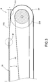
FIG. 3 is a partial enlarged view illustrating the three-dimensional printing system according to the first embodiment of the present disclosure; -
FIG. 4 is another partial enlarged view illustrating the three-dimensional printing system according to the first embodiment of the present disclosure; -
FIG. 5 is a first in-use view illustrating the three-dimensional printing system according to the first embodiment of the present disclosure; -
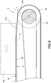
FIG. 6 is a second in-use view illustrating the three-dimensional printing system according to the first embodiment of the present disclosure; -
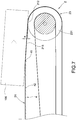
FIG. 7 is a third in-use view illustrating the three-dimensional printing system according to the first embodiment of the present disclosure; -
FIG. 8 is a schematic in-use view illustrating the three-dimensional printing system according to the second not claimed embodiment of the present disclosure; -
FIG. 9 is a partial enlarged view illustrating the three-dimensional printing system according to the second not claimed embodiment of the present disclosure; and -
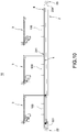
FIG. 10 is a cross-sectional view illustrating the three-dimensional printing system according to the third embodiment of the present disclosure. - Detailed descriptions and technical contents of the present disclosure are illustrated below in conjunction with the accompanying drawings. However, it is to be understood that the descriptions and the accompanying drawings disclosed herein are merely illustrative and exemplary and not intended to limit the scope of the present disclosure.
- Referring to
Figs. 1 to 7 , the present disclosure provides a three-dimensional printing system used for printing out anobject 100. The three-dimensional printing system 10 includes asupport plate 1, asupport plate 1, adelivery module 2, one ormultiple printing devices 3, and anobject detaching member 4. - As shown in
Figs. 1 to 7 , thesupport plate 1 is a hard flat plate made of metal, plastic, a ceramic material, or other suitable material. Thesupport plate 1 has anupper surface 11. - As shown in
Figs. 1 to 7 , thedelivery module 2 includes abelt 21 covering thesupport plate 1. Theupper surface 11 of thesupport plate 1 is in contact with thebelt 21. Thebelt 21 includes aprinting area 211 above thesupport plate 1 and includes aseparation section 212 at one side of thesupport plate 1. - In detail, the
delivery module 2 further includes afirst roller 22 and asecond roller 23, thefirst roller 22 and thesecond roller 23 are disposed at two sides of thesupport plate 1 to drive thebelt 21 to move with respect to thesupport plate 1, and theseparation section 212 is an area of thebelt 21 in contact with thesecond roller 23. Thefirst roller 22 is adrive wheel 221 actively driving thebelt 21, and thesecond roller 23 is an idler 231 passively driving thebelt 21; however, the present disclosure is not limited in this regard. - As shown in
Figs. 1 ,2 and5 , theprinting device 3 is disposed corresponding to thesupport plate 1, theobject 100 is formed layer by layer in theprinting area 211 via theprinting device 3 and is moved away by thebelt 21 after theobject 100 is completely printed out. - As shown in
Figs. 1 to 7 , theobject detaching member 4 is disposed under thebelt 21 and between thesupport plate 1 and theseparation section 212. Theobject detaching member 4 includes anabutment portion 41 abutted against thebelt 21, and theabutment portion 41 is at a position higher than a position of theseparation section 212 to form a height level difference h therebetween, so that thebelt 21 includes aninclined section 213 between theabutment portion 41 and theseparation section 212, and a height level of theinclined section 213 gradually decreases in a direction away from theabutment portion 41, and thereby theobject 100 is detached from thebelt 21 when theobject 100 is moved to theseparation section 212. - Furthermore, the
object detaching member 4 is an extendingplate 4 extended from one side of thesupport plate 1, and theabutment portion 41 is formed at one end of the extendingplate 42 at one side adjacent to theseparation section 212. Theupper surface 11 and theabutment portion 41 are substantially on the same horizontal plane. - As shown in
Fig. 1 , the three-dimensional printing system 10 further includes amaterial collecting track 5, thematerial collecting track 5 is disposed corresponding to theseparation section 212, and thematerial collecting track 5 includes aninclined surface 51 whose height level decreases in a direction away from theseparation section 212. Therefore, after theobject 100 is detached from thebelt 21, theobject 100 is collected in thematerial collecting track 5 via theinclined surface 51, thus achieving automatic production. - Please refer to
Fig. 1 andFigs. 5 to 7 for in-use views illustrating the three-dimensional printing system 10. After theobject 100 is completely printed out in theprinting area 211, theobject 100 adhered to thebelt 21 is moved with thebelt 21 to theinclined section 213. Thebelt 21 is horizontal before theabutment portion 41, and is inclined after theabutment portion 41 due to the height level difference h. This enables theobject 100 to be gradually detached from thebelt 21, so that theobject 100 is separated from thebelt 21 when theobject 100 is moved to theseparation section 212. As a result, theobject 100 can be successfully collected by thematerial collecting track 5 to achieve automatic production. Accordingly, the need for manually operating a shovel to take down the objects is eliminated, and automatic three-dimensional printing production is achieved. - Please refer to
Figs. 8 and9 for a second not claimed embodiment of the three-dimensional printing system 10. The second embodiment is similar to the first embodiment, except that theobject detaching member 4 of the second embodiment has a different structure. - In detail, the
object detaching member 4 is arod 43, an axis of therod 43 and an axis of thesecond roller 23 are parallel to each other, and theabutment portion 41 is formed at the top of therod 43. By this configuration, thebelt 21 is horizontal before theabutment portion 41, and is inclined after the abutment portion 41 (i.e. the inclined section 213) due to the height level difference h. This causes theobject 100 to be gradually detached from thebelt 21, thereby achieving the same effect as the first embodiment. - Please refer to
Fig. 10 for the third embodiment of the three-dimensional printing system 10. The third embodiment is similar to the first embodiment, except that the third embodiment includesmultiple printing devices 3. - Furthermore, according to a length of the
printing area 211 of thedelivery module 2, one ormultiple printing devices 3 can be arranged, such that themultiple printing devices 3 can be arranged side by side along thesupport plate 1. Themultiple printing devices 3 produce orcolor objects 100 individually. Theprinting devices 3 produce objects 100 respectively at the same time. After completion of printing, theobjects 100 printed out are then sequentially sent to the material collecting track 5 (seeFig. 1 ), thereby achieving mass production and saving production time.
Claims (7)
- A three-dimensional printing system, for printing out an object (100), the three-dimensional printing system (10) comprising:a support plate (1);a delivery module (2) including a belt (21) covering the support plate (1), the belt (21) including a printing area (211) above the support plate (1) and including a separation section (212) at one side of the support plate (1);at least one printing device (3) disposed corresponding to the support plate (1), the object (100) being formed layer by layer in the printing area (211) via the printing device (3) and being moved with the belt (21); characterized by further comprising:an object detaching member (4) disposed under the belt (21) and between the support plate (1) and the separation section (212), the object detaching member (4) including an abutment portion (41) abutted against the belt (21), the abutment portion (41) being at a position higher than a position of the separation section (212) to form a height level difference (h) between the abutment portion (41) and the separation section (212), so that the object (100) is detached from the belt (21) when the object (100) is moved to the separation section (212),wherein the object detaching member (4) is an extending plate (42) extended from one side of the support plate (1), and the abutment portion (41) is formed at one end of the extending plate (42) at one side adjacent to the separation section (212).
- The three-dimensional printing system according to claim 1, wherein the belt (21) including an inclined section (213) between the abutment portion (41) and the separation section (212), and a height level of the inclined section (213) gradually decreases in a direction away from the abutment portion (41).
- The three-dimensional printing system according to claim 1, wherein the delivery module (2) further includes a first roller (22) and a second roller (23), the first roller (22) and the second roller (23) are disposed at two sides of the support plate (1) to drive the belt (21) to move with respect to the support plate (1), and the separation section (212) is an area of the belt (21) in contact with the second roller (23).
- The three-dimensional printing system according to claim 1, wherein the support plate (1) includes an upper surface (11) in contact with the belt (21), and the upper surface (11) and the abutment portion (41) are on the same horizontal plane.
- The three-dimensional printing system according to claim 1, wherein the three-dimensional printing system includes multiple printing devices (3), and the multiple printing devices (3) are arranged side by side along the support plate (1).
- The three-dimensional printing system according to claim 1, further comprising a material collecting track (5), the material collecting track (5) being disposed corresponding to the separation section (212), the material collecting track (5) including an inclined surface (51) whose height level decreases in a direction away from the separation section (212).
- The three-dimensional printing system according to claim 1, wherein the delivery module (2) further includes a first roller (22) and a second roller (23), the first roller (22) and the second roller (23) are disposed at two sides of the support plate (1) to drive the belt (21) to move with respect to the support plate (1), the separation section (212) is an area of the belt (21) in contact with the second roller (23), the first roller (22) is a drive wheel (221) actively driving the belt (21), and the second roller (23) is an idler (231) passively driving the belt (21).
Applications Claiming Priority (1)
| Application Number | Priority Date | Filing Date | Title |
|---|---|---|---|
| CN201810044298.4A CN110039778A (en) | 2018-01-17 | 2018-01-17 | Three-dimensional printing system |
Publications (2)
| Publication Number | Publication Date |
|---|---|
| EP3513952A1 EP3513952A1 (en) | 2019-07-24 |
| EP3513952B1 true EP3513952B1 (en) | 2020-09-16 |
Family
ID=61763787
Family Applications (1)
| Application Number | Title | Priority Date | Filing Date |
|---|---|---|---|
| EP18162774.6A Not-in-force EP3513952B1 (en) | 2018-01-17 | 2018-03-20 | Three-dimensional printing system |
Country Status (5)
| Country | Link |
|---|---|
| US (1) | US20190217507A1 (en) |
| EP (1) | EP3513952B1 (en) |
| JP (1) | JP6533847B1 (en) |
| CN (1) | CN110039778A (en) |
| ES (1) | ES2831035T3 (en) |
Families Citing this family (1)
| Publication number | Priority date | Publication date | Assignee | Title |
|---|---|---|---|---|
| WO2022069987A1 (en) * | 2020-10-02 | 2022-04-07 | 3M Innovative Properties Company | 3d printing system and method for manufacturing workpieces and adapter set for attaching workpiece holders to a 3d printing device |
Family Cites Families (5)
| Publication number | Priority date | Publication date | Assignee | Title |
|---|---|---|---|---|
| US20170259507A1 (en) * | 2014-12-01 | 2017-09-14 | Sabic Global Technologies B.V. | Additive manufacturing process automation systems and methods |
| CN206493591U (en) * | 2016-11-24 | 2017-09-15 | 无锡金谷三维科技有限公司 | One kind realizes the continuous continual process units of ink-jet 3D printing |
| CN107081902A (en) * | 2017-06-28 | 2017-08-22 | 辽宁三维蚂蚁科技有限公司 | It is a kind of to remove the increasing material former and its forming method of shaping workpiece automatically |
| CN206884176U (en) * | 2017-06-28 | 2018-01-16 | 辽宁三维蚂蚁科技有限公司 | A kind of increasing material former that can remove shaping workpiece automatically |
| CN107081909A (en) * | 2017-06-29 | 2017-08-22 | 温州启龙电子科技有限公司 | A kind of new 3D printer |
-
2018
- 2018-01-17 CN CN201810044298.4A patent/CN110039778A/en active Pending
- 2018-03-15 US US15/922,434 patent/US20190217507A1/en not_active Abandoned
- 2018-03-20 ES ES18162774T patent/ES2831035T3/en active Active
- 2018-03-20 EP EP18162774.6A patent/EP3513952B1/en not_active Not-in-force
- 2018-03-28 JP JP2018063056A patent/JP6533847B1/en not_active Expired - Fee Related
Also Published As
| Publication number | Publication date |
|---|---|
| CN110039778A (en) | 2019-07-23 |
| EP3513952A1 (en) | 2019-07-24 |
| US20190217507A1 (en) | 2019-07-18 |
| JP6533847B1 (en) | 2019-06-19 |
| ES2831035T3 (en) | 2021-06-07 |
| JP2019123223A (en) | 2019-07-25 |
Similar Documents
| Publication | Publication Date | Title |
|---|---|---|
| US11904536B2 (en) | Method and apparatus for automated composite-based additive manufacturing | |
| JP4705139B2 (en) | Laser cutting device, laser cutting method and laser cutting system | |
| CN104582873B (en) | Method and apparatus for removing substantitally planar workpiece at the top of workpiece heap | |
| KR20170035684A (en) | Materials unloading system | |
| KR101397487B1 (en) | Dividing apparatus | |
| JP2009120357A (en) | Method and mechanism for separately feeding storage battery electrode plate | |
| CN113437605A (en) | Electronic connector assembling method | |
| CN210942645U (en) | SMT (surface mount technology) casting automation equipment | |
| EP2530037B1 (en) | Method and system for processing a layer of products from a pallet | |
| EP3513952A1 (en) | Three-dimensional printing system | |
| CN210046265U (en) | Feeding mechanism | |
| JP2000511695A (en) | Printed circuit board manufacturing equipment | |
| JP2008531437A (en) | Apparatus and method for supporting and moving a processing material using a cutting apparatus | |
| CN113800282A (en) | Dust collection mechanism of plate transfer machine | |
| CN211455709U (en) | Series welding device | |
| KR20200088939A (en) | attachment for dense tape | |
| CN216165605U (en) | Automatic line drawing machine for vamp processing | |
| CN212687127U (en) | Fabric cutting equipment | |
| CN211362373U (en) | Vertical paperboard paper cutting machine | |
| JP3035737B1 (en) | Loading method and loading device for printed wiring board, etc., and receiving method and receiving device | |
| CN111703948A (en) | Fabric cutting equipment | |
| JP3767708B2 (en) | Work transfer device | |
| CN110549411B (en) | Ejecting net device | |
| CN109843765B (en) | Switching and ejecting device and method for plate-like elements | |
| JPH079162A (en) | Device for cutting microjoint of iron plate |
Legal Events
| Date | Code | Title | Description |
|---|---|---|---|
| PUAI | Public reference made under article 153(3) epc to a published international application that has entered the european phase |
Free format text: ORIGINAL CODE: 0009012 |
|
| STAA | Information on the status of an ep patent application or granted ep patent |
Free format text: STATUS: THE APPLICATION HAS BEEN PUBLISHED |
|
| AK | Designated contracting states |
Kind code of ref document: A1 Designated state(s): AL AT BE BG CH CY CZ DE DK EE ES FI FR GB GR HR HU IE IS IT LI LT LU LV MC MK MT NL NO PL PT RO RS SE SI SK SM TR |
|
| AX | Request for extension of the european patent |
Extension state: BA ME |
|
| STAA | Information on the status of an ep patent application or granted ep patent |
Free format text: STATUS: REQUEST FOR EXAMINATION WAS MADE |
|
| 17P | Request for examination filed |
Effective date: 20200116 |
|
| RBV | Designated contracting states (corrected) |
Designated state(s): AL AT BE BG CH CY CZ DE DK EE ES FI FR GB GR HR HU IE IS IT LI LT LU LV MC MK MT NL NO PL PT RO RS SE SI SK SM TR |
|
| GRAP | Despatch of communication of intention to grant a patent |
Free format text: ORIGINAL CODE: EPIDOSNIGR1 |
|
| STAA | Information on the status of an ep patent application or granted ep patent |
Free format text: STATUS: GRANT OF PATENT IS INTENDED |
|
| INTG | Intention to grant announced |
Effective date: 20200630 |
|
| RIN1 | Information on inventor provided before grant (corrected) |
Inventor name: LEE, YANG-TEH Inventor name: CHIU, YI-MIN |
|
| GRAS | Grant fee paid |
Free format text: ORIGINAL CODE: EPIDOSNIGR3 |
|
| GRAA | (expected) grant |
Free format text: ORIGINAL CODE: 0009210 |
|
| STAA | Information on the status of an ep patent application or granted ep patent |
Free format text: STATUS: THE PATENT HAS BEEN GRANTED |
|
| AK | Designated contracting states |
Kind code of ref document: B1 Designated state(s): AL AT BE BG CH CY CZ DE DK EE ES FI FR GB GR HR HU IE IS IT LI LT LU LV MC MK MT NL NO PL PT RO RS SE SI SK SM TR |
|
| REG | Reference to a national code |
Ref country code: GB Ref legal event code: FG4D |
|
| REG | Reference to a national code |
Ref country code: CH Ref legal event code: EP |
|
| REG | Reference to a national code |
Ref country code: DE Ref legal event code: R096 Ref document number: 602018007793 Country of ref document: DE |
|
| REG | Reference to a national code |
Ref country code: IE Ref legal event code: FG4D |
|
| REG | Reference to a national code |
Ref country code: AT Ref legal event code: REF Ref document number: 1313767 Country of ref document: AT Kind code of ref document: T Effective date: 20201015 |
|
| PG25 | Lapsed in a contracting state [announced via postgrant information from national office to epo] |
Ref country code: SE Free format text: LAPSE BECAUSE OF FAILURE TO SUBMIT A TRANSLATION OF THE DESCRIPTION OR TO PAY THE FEE WITHIN THE PRESCRIBED TIME-LIMIT Effective date: 20200916 Ref country code: BG Free format text: LAPSE BECAUSE OF FAILURE TO SUBMIT A TRANSLATION OF THE DESCRIPTION OR TO PAY THE FEE WITHIN THE PRESCRIBED TIME-LIMIT Effective date: 20201216 Ref country code: HR Free format text: LAPSE BECAUSE OF FAILURE TO SUBMIT A TRANSLATION OF THE DESCRIPTION OR TO PAY THE FEE WITHIN THE PRESCRIBED TIME-LIMIT Effective date: 20200916 Ref country code: GR Free format text: LAPSE BECAUSE OF FAILURE TO SUBMIT A TRANSLATION OF THE DESCRIPTION OR TO PAY THE FEE WITHIN THE PRESCRIBED TIME-LIMIT Effective date: 20201217 Ref country code: NO Free format text: LAPSE BECAUSE OF FAILURE TO SUBMIT A TRANSLATION OF THE DESCRIPTION OR TO PAY THE FEE WITHIN THE PRESCRIBED TIME-LIMIT Effective date: 20201216 Ref country code: FI Free format text: LAPSE BECAUSE OF FAILURE TO SUBMIT A TRANSLATION OF THE DESCRIPTION OR TO PAY THE FEE WITHIN THE PRESCRIBED TIME-LIMIT Effective date: 20200916 |
|
| REG | Reference to a national code |
Ref country code: AT Ref legal event code: MK05 Ref document number: 1313767 Country of ref document: AT Kind code of ref document: T Effective date: 20200916 |
|
| REG | Reference to a national code |
Ref country code: NL Ref legal event code: MP Effective date: 20200916 |
|
| PG25 | Lapsed in a contracting state [announced via postgrant information from national office to epo] |
Ref country code: RS Free format text: LAPSE BECAUSE OF FAILURE TO SUBMIT A TRANSLATION OF THE DESCRIPTION OR TO PAY THE FEE WITHIN THE PRESCRIBED TIME-LIMIT Effective date: 20200916 Ref country code: LV Free format text: LAPSE BECAUSE OF FAILURE TO SUBMIT A TRANSLATION OF THE DESCRIPTION OR TO PAY THE FEE WITHIN THE PRESCRIBED TIME-LIMIT Effective date: 20200916 |
|
| REG | Reference to a national code |
Ref country code: LT Ref legal event code: MG4D |
|
| PG25 | Lapsed in a contracting state [announced via postgrant information from national office to epo] |
Ref country code: LT Free format text: LAPSE BECAUSE OF FAILURE TO SUBMIT A TRANSLATION OF THE DESCRIPTION OR TO PAY THE FEE WITHIN THE PRESCRIBED TIME-LIMIT Effective date: 20200916 Ref country code: SM Free format text: LAPSE BECAUSE OF FAILURE TO SUBMIT A TRANSLATION OF THE DESCRIPTION OR TO PAY THE FEE WITHIN THE PRESCRIBED TIME-LIMIT Effective date: 20200916 Ref country code: PT Free format text: LAPSE BECAUSE OF FAILURE TO SUBMIT A TRANSLATION OF THE DESCRIPTION OR TO PAY THE FEE WITHIN THE PRESCRIBED TIME-LIMIT Effective date: 20210118 Ref country code: RO Free format text: LAPSE BECAUSE OF FAILURE TO SUBMIT A TRANSLATION OF THE DESCRIPTION OR TO PAY THE FEE WITHIN THE PRESCRIBED TIME-LIMIT Effective date: 20200916 Ref country code: CZ Free format text: LAPSE BECAUSE OF FAILURE TO SUBMIT A TRANSLATION OF THE DESCRIPTION OR TO PAY THE FEE WITHIN THE PRESCRIBED TIME-LIMIT Effective date: 20200916 Ref country code: EE Free format text: LAPSE BECAUSE OF FAILURE TO SUBMIT A TRANSLATION OF THE DESCRIPTION OR TO PAY THE FEE WITHIN THE PRESCRIBED TIME-LIMIT Effective date: 20200916 |
|
| PGFP | Annual fee paid to national office [announced via postgrant information from national office to epo] |
Ref country code: IT Payment date: 20210331 Year of fee payment: 4 |
|
| PG25 | Lapsed in a contracting state [announced via postgrant information from national office to epo] |
Ref country code: PL Free format text: LAPSE BECAUSE OF FAILURE TO SUBMIT A TRANSLATION OF THE DESCRIPTION OR TO PAY THE FEE WITHIN THE PRESCRIBED TIME-LIMIT Effective date: 20200916 Ref country code: IS Free format text: LAPSE BECAUSE OF FAILURE TO SUBMIT A TRANSLATION OF THE DESCRIPTION OR TO PAY THE FEE WITHIN THE PRESCRIBED TIME-LIMIT Effective date: 20210116 Ref country code: AL Free format text: LAPSE BECAUSE OF FAILURE TO SUBMIT A TRANSLATION OF THE DESCRIPTION OR TO PAY THE FEE WITHIN THE PRESCRIBED TIME-LIMIT Effective date: 20200916 Ref country code: AT Free format text: LAPSE BECAUSE OF FAILURE TO SUBMIT A TRANSLATION OF THE DESCRIPTION OR TO PAY THE FEE WITHIN THE PRESCRIBED TIME-LIMIT Effective date: 20200916 |
|
| REG | Reference to a national code |
Ref country code: ES Ref legal event code: FG2A Ref document number: 2831035 Country of ref document: ES Kind code of ref document: T3 Effective date: 20210607 |
|
| REG | Reference to a national code |
Ref country code: DE Ref legal event code: R097 Ref document number: 602018007793 Country of ref document: DE |
|
| PG25 | Lapsed in a contracting state [announced via postgrant information from national office to epo] |
Ref country code: SK Free format text: LAPSE BECAUSE OF FAILURE TO SUBMIT A TRANSLATION OF THE DESCRIPTION OR TO PAY THE FEE WITHIN THE PRESCRIBED TIME-LIMIT Effective date: 20200916 |
|
| PLBE | No opposition filed within time limit |
Free format text: ORIGINAL CODE: 0009261 |
|
| STAA | Information on the status of an ep patent application or granted ep patent |
Free format text: STATUS: NO OPPOSITION FILED WITHIN TIME LIMIT |
|
| 26N | No opposition filed |
Effective date: 20210617 |
|
| PG25 | Lapsed in a contracting state [announced via postgrant information from national office to epo] |
Ref country code: SI Free format text: LAPSE BECAUSE OF FAILURE TO SUBMIT A TRANSLATION OF THE DESCRIPTION OR TO PAY THE FEE WITHIN THE PRESCRIBED TIME-LIMIT Effective date: 20200916 Ref country code: DK Free format text: LAPSE BECAUSE OF FAILURE TO SUBMIT A TRANSLATION OF THE DESCRIPTION OR TO PAY THE FEE WITHIN THE PRESCRIBED TIME-LIMIT Effective date: 20200916 |
|
| REG | Reference to a national code |
Ref country code: DE Ref legal event code: R119 Ref document number: 602018007793 Country of ref document: DE |
|
| PG25 | Lapsed in a contracting state [announced via postgrant information from national office to epo] |
Ref country code: MC Free format text: LAPSE BECAUSE OF FAILURE TO SUBMIT A TRANSLATION OF THE DESCRIPTION OR TO PAY THE FEE WITHIN THE PRESCRIBED TIME-LIMIT Effective date: 20200916 |
|
| REG | Reference to a national code |
Ref country code: CH Ref legal event code: PL |
|
| REG | Reference to a national code |
Ref country code: BE Ref legal event code: MM Effective date: 20210331 |
|
| PG25 | Lapsed in a contracting state [announced via postgrant information from national office to epo] |
Ref country code: FR Free format text: LAPSE BECAUSE OF NON-PAYMENT OF DUE FEES Effective date: 20210331 Ref country code: IE Free format text: LAPSE BECAUSE OF NON-PAYMENT OF DUE FEES Effective date: 20210320 Ref country code: LI Free format text: LAPSE BECAUSE OF NON-PAYMENT OF DUE FEES Effective date: 20210331 Ref country code: LU Free format text: LAPSE BECAUSE OF NON-PAYMENT OF DUE FEES Effective date: 20210320 Ref country code: DE Free format text: LAPSE BECAUSE OF NON-PAYMENT OF DUE FEES Effective date: 20211001 Ref country code: CH Free format text: LAPSE BECAUSE OF NON-PAYMENT OF DUE FEES Effective date: 20210331 |
|
| REG | Reference to a national code |
Ref country code: ES Ref legal event code: FD2A Effective date: 20220517 |
|
| PG25 | Lapsed in a contracting state [announced via postgrant information from national office to epo] |
Ref country code: ES Free format text: LAPSE BECAUSE OF NON-PAYMENT OF DUE FEES Effective date: 20210321 Ref country code: BE Free format text: LAPSE BECAUSE OF NON-PAYMENT OF DUE FEES Effective date: 20210331 |
|
| GBPC | Gb: european patent ceased through non-payment of renewal fee |
Effective date: 20220320 |
|
| PG25 | Lapsed in a contracting state [announced via postgrant information from national office to epo] |
Ref country code: GB Free format text: LAPSE BECAUSE OF NON-PAYMENT OF DUE FEES Effective date: 20220320 |
|
| PG25 | Lapsed in a contracting state [announced via postgrant information from national office to epo] |
Ref country code: IT Free format text: LAPSE BECAUSE OF NON-PAYMENT OF DUE FEES Effective date: 20220320 |
|
| PG25 | Lapsed in a contracting state [announced via postgrant information from national office to epo] |
Ref country code: NL Free format text: LAPSE BECAUSE OF NON-PAYMENT OF DUE FEES Effective date: 20200923 Ref country code: CY Free format text: LAPSE BECAUSE OF FAILURE TO SUBMIT A TRANSLATION OF THE DESCRIPTION OR TO PAY THE FEE WITHIN THE PRESCRIBED TIME-LIMIT Effective date: 20200916 |
|
| PG25 | Lapsed in a contracting state [announced via postgrant information from national office to epo] |
Ref country code: HU Free format text: LAPSE BECAUSE OF FAILURE TO SUBMIT A TRANSLATION OF THE DESCRIPTION OR TO PAY THE FEE WITHIN THE PRESCRIBED TIME-LIMIT; INVALID AB INITIO Effective date: 20180320 |
|
| PG25 | Lapsed in a contracting state [announced via postgrant information from national office to epo] |
Ref country code: MK Free format text: LAPSE BECAUSE OF FAILURE TO SUBMIT A TRANSLATION OF THE DESCRIPTION OR TO PAY THE FEE WITHIN THE PRESCRIBED TIME-LIMIT Effective date: 20200916 |
|
| PG25 | Lapsed in a contracting state [announced via postgrant information from national office to epo] |
Ref country code: TR Free format text: LAPSE BECAUSE OF FAILURE TO SUBMIT A TRANSLATION OF THE DESCRIPTION OR TO PAY THE FEE WITHIN THE PRESCRIBED TIME-LIMIT Effective date: 20200916 |
|
| PG25 | Lapsed in a contracting state [announced via postgrant information from national office to epo] |
Ref country code: MT Free format text: LAPSE BECAUSE OF FAILURE TO SUBMIT A TRANSLATION OF THE DESCRIPTION OR TO PAY THE FEE WITHIN THE PRESCRIBED TIME-LIMIT Effective date: 20200916 |