EP3513645B1 - A cutting plate with a safety device for locking the cutting blade - Google Patents
A cutting plate with a safety device for locking the cutting blade Download PDFInfo
- Publication number
- EP3513645B1 EP3513645B1 EP18212566.6A EP18212566A EP3513645B1 EP 3513645 B1 EP3513645 B1 EP 3513645B1 EP 18212566 A EP18212566 A EP 18212566A EP 3513645 B1 EP3513645 B1 EP 3513645B1
- Authority
- EP
- European Patent Office
- Prior art keywords
- plate
- cutting plate
- lever
- bracket
- cutting
- Prior art date
- Legal status (The legal status is an assumption and is not a legal conclusion. Google has not performed a legal analysis and makes no representation as to the accuracy of the status listed.)
- Active
Links
Images



Classifications
-
- A—HUMAN NECESSITIES
- A01—AGRICULTURE; FORESTRY; ANIMAL HUSBANDRY; HUNTING; TRAPPING; FISHING
- A01D—HARVESTING; MOWING
- A01D34/00—Mowers; Mowing apparatus of harvesters
- A01D34/01—Mowers; Mowing apparatus of harvesters characterised by features relating to the type of cutting apparatus
- A01D34/412—Mowers; Mowing apparatus of harvesters characterised by features relating to the type of cutting apparatus having rotating cutters
- A01D34/63—Mowers; Mowing apparatus of harvesters characterised by features relating to the type of cutting apparatus having rotating cutters having cutters rotating about a vertical axis
- A01D34/64—Mowers; Mowing apparatus of harvesters characterised by features relating to the type of cutting apparatus having rotating cutters having cutters rotating about a vertical axis mounted on a vehicle, e.g. a tractor, or drawn by an animal or a vehicle
-
- A—HUMAN NECESSITIES
- A01—AGRICULTURE; FORESTRY; ANIMAL HUSBANDRY; HUNTING; TRAPPING; FISHING
- A01D—HARVESTING; MOWING
- A01D34/00—Mowers; Mowing apparatus of harvesters
- A01D34/01—Mowers; Mowing apparatus of harvesters characterised by features relating to the type of cutting apparatus
- A01D34/412—Mowers; Mowing apparatus of harvesters characterised by features relating to the type of cutting apparatus having rotating cutters
- A01D34/63—Mowers; Mowing apparatus of harvesters characterised by features relating to the type of cutting apparatus having rotating cutters having cutters rotating about a vertical axis
- A01D34/82—Other details
- A01D34/828—Safety devices
-
- A—HUMAN NECESSITIES
- A01—AGRICULTURE; FORESTRY; ANIMAL HUSBANDRY; HUNTING; TRAPPING; FISHING
- A01D—HARVESTING; MOWING
- A01D34/00—Mowers; Mowing apparatus of harvesters
- A01D34/01—Mowers; Mowing apparatus of harvesters characterised by features relating to the type of cutting apparatus
- A01D34/412—Mowers; Mowing apparatus of harvesters characterised by features relating to the type of cutting apparatus having rotating cutters
- A01D34/63—Mowers; Mowing apparatus of harvesters characterised by features relating to the type of cutting apparatus having rotating cutters having cutters rotating about a vertical axis
- A01D34/64—Mowers; Mowing apparatus of harvesters characterised by features relating to the type of cutting apparatus having rotating cutters having cutters rotating about a vertical axis mounted on a vehicle, e.g. a tractor, or drawn by an animal or a vehicle
- A01D2034/645—Lifting means for the cutter of the lawnmower mounted at the front of the vehicle for inspection and maintenance
Definitions
- the present invention relates to a cutting plate with a safety device for locking the cutting blade.
- Lawn tractors comprising a cutting plate separably associated with the front part of the tractor are known. This allows different types of cutting plates to be associated with the same tractor according to the needs, e.g. a cutting plate with several cutting blades connected by transmission belts.
- the lifting plate is normally lifted, by gripping it at the front part thereof, causing a rotation of 40°-60° so as to make the cutting area accessible while keeping the tractor still with the wheels resting on the ground.
- said devices do not allow the rotation of the cutting blade to be prevented except by removing the transmission belt.
- the operator is thus able to move the cutting plate between the working position and the washing position with two simple movements, lifting and lowering.
- the plate 2 further comprises a bodywork 5 to which said tubular element 4 is fastened, and with which are rotatably associated three rotors 61-63 to which respective cutting blades 64 ( figure 10 ) are inferiorly fixed.
- the assembly of the bodywork 5 and the tubular element 4 forms a frame 50 for the cutting plate 2 of the lawnmower 1.
- a driving belt 71 is associated with said rotor 61 connected to the motor of tractor 30.
- a first end 81 of a wire 8 is fixed to a lever 3 the second end 82 of which is fixed to a body 9 which is selectively movable between a locking position and a rotor releasing position 61.
- the body 9 meshes the toothed crown 62.
- Said spring 11 serves to force the rotation of the body 9 in the locking direction of the rotor 61 (anti-clockwise looking at figures 3, 4 ).
- a second safety spring 111 connected to the plate 10 and the body 9 in different points with respect to said spring 11.
- a bracket 41 is fixed to the tubular element 4 with which a portion of wire 8 is slidably associated, close to the connection of the lever 3.
- the rotation of the bracket 43 is controlled by a wire 13 connected to the bracket 43 by means of a spring 14.
- Said wire 13 ends at a small lever 15.
- the bracket 17 comprises a tooth 171 able to be coupled to a tooth 161 of the lever 16.
- a spring 120 similar to spring 12 connects bracket 17 to one end 330 of the lever 16.
- the lever 3 is in a releasing position in which it pulls the wire 8, thus overcoming the force of the spring 11 while keeping the body 9 disengaged from the toothed crown 65 of the rotor 61.
- the rotors 61-63 can rotate.
- the plate 2 is in a cutting position.
- lever 16 is always kept parallel to the lever 3.
- the levers 3, 16 are constrained to the connections 31 of the tractor 30 stably resting on the ground.
- connections 31 are rotatably associated with front rings 35 of the front wheels 36 of the tractor 30.
- the levers 3, 16 rotate with respect to said front rings 35.
- the plate 2 is locked in an inclined position because the teeth 42, 171 of the brackets 43, 17 mesh the teeth 32, 162 of the levers 3, 16.
- the weight of the plate 2 is used during the lowering step to overcome the force of the meshing of the body 9 with the toothed wheel 65.
- the operator is thus able to move the cutting plate 2 between the working position and the washing position with two simple movements, lifting and lowering.
- the driving belt 71 does not need to be disassociated from rotor 61, nor from the tractor motor.
- the plate 2 could be free from the tubular element 4, the levers 3, 16 being able to be directly and rotatably associated with the bodywork 5 by means of appropriate connection points.
- the bodywork 5 corresponds to the frame 50.
- the body 9 can be slidably associated with the plate 10, so that the locking/releasing movement is translational.
Landscapes
- Life Sciences & Earth Sciences (AREA)
- Environmental Sciences (AREA)
- Soil Working Implements (AREA)
Description
- The present invention relates to a cutting plate with a safety device for locking the cutting blade.
- Lawn tractors comprising a cutting plate separably associated with the front part of the tractor are known. This allows different types of cutting plates to be associated with the same tractor according to the needs, e.g. a cutting plate with several cutting blades connected by transmission belts.
- After several work sessions, the need arises to clean the cutting area without separating the cutting plate from the tractor.
- The lifting plate is normally lifted, by gripping it at the front part thereof, causing a rotation of 40°-60° so as to make the cutting area accessible while keeping the tractor still with the wheels resting on the ground.
- Systems allowing the cutting plate to be kept in a raised and inclined position are known.
- The problem of preventing the accidental start of the cutting blade occurs when the cutting blade is in a raised position, i.e. in a washing position.
- The mainly adopted solution consists in removing the driving belt manually.
-
EP-2649871 describes a lawnmower with an inclinable cutting plate in a washing position, comprising a mechanism for locking the plate in an inclined position and which can be operated by the operator. -
US-2016/0050847 shows a lawnmower with an inclinable cutting plate comprising a device which allows the plate to be lifted without removing the belt. -
EP-1654921 describes a cutting plate for a tractor. Said cutting plate comprises a lever, which is rotatably associated with a frame of the cutting plate and separably associated with the tractor. - Disadvantageously, said devices do not allow the rotation of the cutting blade to be prevented except by removing the transmission belt.
- It is an object of the present invention to manufacture an inclinable cutting plate which is separably associable with a tractor, comprising a safety device which allows the cutting blade to be locked when lifting the cutting plate.
- It is a further object of the present invention that said safety device is automatically operated when lifting the cutting plate.
- It is a yet further object of the present invention that said safety device is simple to be manufactured and does not require modifications of the kinematic mechanism which allows the rotation of the cutting blade.
- According to the invention, said and further objects are achieved by a cutting plate as defined in
claim 1. - Advantageously, the weight of the cutting plate is used during the lowering step in order to overcome the force of the engagement of the body with the rotor.
- The operator is thus able to move the cutting plate between the working position and the washing position with two simple movements, lifting and lowering.
- In the washing position, there is no risk for the operator because the rotor is locked without removing the driving belt.
- These and other features of the present invention will become more apparent from the following detailed description of a practical embodiment thereof, shown by way of a non-limiting example in the accompanying drawings, in which:
-
figure 1 shows a side view of a cutting plate in a lowered working position; -
figure 2 shows a side view of the cutting plate in a raised washing position; -
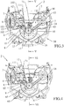
figure 3 shows a top plan view of the cutting plate in a lowered position; -
figure 4 shows a section view according to line IV-IV offigure 2 ; -
figure 5 shows a section view according to line V-V offigure 3 ; -
figure 6 shows a section view according to line VI-VI offigure 3 ; -
figure 7 shows a side view of a lawnmower with the cutting plate in a lowered position; -
figure 8 shows a side view of the lawnmower with the cutting plate in a raised position; -
figure 9 shows a front side view of the lawnmower with the cutting plate in a lowered position; -
figure 10 shows a front view of the lawnmower with the cutting plate in a raised position. - A
lawnmower 1 comprises atractor 30 and a cutting plate 2 (figures 7-10 ). - The
cutting plate 2 is separably associated withfront connections 31 of thetractor 30 by means ofrespective levers - When fixed to the
respective connections 31, thelevers tractor 30. - Said
levers tubular element 4 of theplate 2. - The
plate 2 further comprises abodywork 5 to which saidtubular element 4 is fastened, and with which are rotatably associated three rotors 61-63 to which respective cutting blades 64 (figure 10 ) are inferiorly fixed. - The assembly of the
bodywork 5 and thetubular element 4 forms aframe 50 for thecutting plate 2 of thelawnmower 1. - Said rotors 61-63 are connected to one another by means of a
belt 7, and arotor 61 provided with atoothed crown 65. - A
driving belt 71 is associated with saidrotor 61 connected to the motor oftractor 30. - A
first end 81 of awire 8 is fixed to alever 3 thesecond end 82 of which is fixed to abody 9 which is selectively movable between a locking position and arotor releasing position 61. - In the locked position, the
body 9 meshes thetoothed crown 62. - The
body 9 is rotatably connected to aplate 10 fixed to thebodywork 5. - Said
plate 10 comprises afirst edge 101 to which is fastened aconnection element 102 with which a portion of thewire 8 is slidably associated. - One end of a
spring 11, the second end of which is fixed to thebody 9, is fastened to asecond edge 103 of theplate 10. - Said
spring 11 serves to force the rotation of thebody 9 in the locking direction of the rotor 61 (anti-clockwise looking atfigures 3, 4 ). - Preferably, there is provided a
second safety spring 111 connected to theplate 10 and thebody 9 in different points with respect to saidspring 11. - A
bracket 41 is fixed to thetubular element 4 with which a portion ofwire 8 is slidably associated, close to the connection of thelever 3. - At the connection of the
tubular element 4, thelever 3 comprises oneend 33 comprising atooth 32 able to be coupled to atooth 42 of abracket 43 which is rotatably associated with thetubular element 4. - A
spring 12 comprises a first end associated with thebracket 43 and a second end associated with theend 33 of thelever 3. Saidspring 12 allows the sealing of the coupling between theteeth - The rotation of the
bracket 43 is controlled by awire 13 connected to thebracket 43 by means of aspring 14. - Said
wire 13 ends at asmall lever 15. - The coupling of said
teeth plate 2 to be kept in an inclined (raised) position for washing, which will become clearer later on. - The
lever 16 is similar to saidlever 3 but free from the connection for a locking/releasing wire, such aswire 8. - Like the
lever 3, thelever 16 comprises an end with which abracket 17 is associated and which is identical to thebracket 43, and awire 18 for controlling said bracket 17 (by means of a spring 140), which ends in asmall lever 19 having the same function assmall lever 15. - The
bracket 17 comprises atooth 171 able to be coupled to atooth 161 of thelever 16. Aspring 120 similar tospring 12 connectsbracket 17 to one end 330 of thelever 16. - Operatively, in the working position in which
plate 2 is lowered (figures 1 ,3 ,5 ,9 ), thelever 3 is in a releasing position in which it pulls thewire 8, thus overcoming the force of thespring 11 while keeping thebody 9 disengaged from thetoothed crown 65 of therotor 61. - In said configuration, the rotors 61-63 can rotate. The
plate 2 is in a cutting position. - Note that the
lever 16 is always kept parallel to thelever 3. - If the operator wants to wash the
plate 2, he/she only needs to take theframe 4 and lift theplate 2, using therear wheels 20 ofplate 2 as a fulcrum. - The
levers connections 31 of thetractor 30 stably resting on the ground. - As apparent from
figures 7, 8 , theconnections 31 are rotatably associated withfront rings 35 of thefront wheels 36 of thetractor 30. - The
levers front rings 35. - In turn, the
frame 50, consisting of thebodywork 5 and thetubular element 4, which are integral with each other, rotates with respect to saidlevers - The rotation of the
bodywork 5 with respect to thelever 3 loosens the pulling action on thewire 8, and therefore thespring 11 forces thebody 9 to rotate towards the toothed wheel 65: after meshing,rotor 61 is locked. - The
plate 2 is locked in an inclined position because theteeth brackets teeth 32, 162 of thelevers - The
plate 2 is ready for washing in safety. - After washing, in order to bring the
plate 2 back into the lowered position, it is sufficient to pull thesmall levers teeth teeth 171, 162, respectively, and accompany the descent of theplate 2, which automatically determines the pulling of thewire 8 which uncouples thebody 9 from thetoothed wheel 65. - Advantageously, the weight of the
plate 2 is used during the lowering step to overcome the force of the meshing of thebody 9 with thetoothed wheel 65. - The operator is thus able to move the
cutting plate 2 between the working position and the washing position with two simple movements, lifting and lowering. - In the washing position, there is no risk for the operator because the rotors 61-63 are locked by a solid meshing connection.
- Advantageously, the driving
belt 71 does not need to be disassociated fromrotor 61, nor from the tractor motor. - Alternatively, the
plate 2 could be free from thetubular element 4, thelevers bodywork 5 by means of appropriate connection points. In such a case, thebodywork 5 corresponds to theframe 50. - Alternatively, the
body 9 can be slidably associated with theplate 10, so that the locking/releasing movement is translational.
Claims (8)
- Cutting plate (2) for tractor (30), comprising a frame (50) with which it is rotatably associated at least one rotor (61) driven by a driving belt (71) and to which a cutting blade (64) is fixed below (64), said cutting plate (2) further comprising at least one lever (3) rotatably associated with the frame (50) and separably associated with the tractor (30),
characterized in that
a first end (81) of a wire (8) is fixed to said lever (3), a second end (82) of the wire (8) is fixed to a body (9) associated with the frame (50), said body (9) being selectively movable between a locking position and a releasing position of the rotor (61), in said locked position the body (9) is reversibly associated with the rotor (61). - Cutting plate (2) according to claim 1, characterized in that said rotor (61) is provided with a toothed crown (65) which in the locking position is adapted to mesh the body (9).
- Cutting plate (2) according to claim 2, characterized in that the body (9) is rotatably connected to the frame (50).
- Cutting plate (2) according to claim 3, characterized in that the body (9) is rotatably connected to a plate (10) fixed to the frame (50), said plate (10) comprises a first edge (101) to which is fastened an element (102) with which a portion of the wire (8) is slidably associated, to a second edge (103) of the plate (10) being fastened an end of at least one spring (11, 111) whose second end is fixed to the body (9).
- Cutting plate (2) according to any one of the preceding claims, characterized in that the frame (50) of the cutting plate (2) comprises a tubular element (4) fixed to a bodywork (5), the lever (3) being rotatably associated with said tubular element (4).
- Cutting plate (2) according to claim 5, characterized in that
the lever (3) is provided with an end (33) comprising a tooth (32) adapted to be coupled with a tooth (42) of a bracket (43) rotatably associated with the tubular element (4),
a spring (12) comprises a first end associated with the bracket (43) and a second end associated with the end (33) of the lever (3),
the rotation of the bracket (43) is controlled by a wire (13) adapted to connect the bracket (43) and a small lever (15). - Cutting plate (2) according to claim 5 or 6, characterized in that a bracket (41) is fixed to the tubular element (4), a portion of the wire (8) is slidably associated with said bracket (41), near the connection of the lever (3).
- Cutting plate (2) according to claim 7, characterized in that it is provided with a second bracket (17) rotatably associated with the tubular element (4), a wire (18) connecting said bracket (17) to a second small lever (19), the second bracket (17) providing a tooth (171) adapted to be coupled with a tooth (161) of a second lever (16), which is separably associated with the tractor (30) and rotatably associated with the frame (50).
Applications Claiming Priority (1)
| Application Number | Priority Date | Filing Date | Title |
|---|---|---|---|
| IT201700149736 | 2017-12-27 |
Publications (2)
| Publication Number | Publication Date |
|---|---|
| EP3513645A1 EP3513645A1 (en) | 2019-07-24 |
| EP3513645B1 true EP3513645B1 (en) | 2020-06-03 |
Family
ID=61873694
Family Applications (1)
| Application Number | Title | Priority Date | Filing Date |
|---|---|---|---|
| EP18212566.6A Active EP3513645B1 (en) | 2017-12-27 | 2018-12-14 | A cutting plate with a safety device for locking the cutting blade |
Country Status (1)
| Country | Link |
|---|---|
| EP (1) | EP3513645B1 (en) |
Families Citing this family (1)
| Publication number | Priority date | Publication date | Assignee | Title |
|---|---|---|---|---|
| SE546147C2 (en) * | 2020-09-23 | 2024-06-11 | Husqvarna Ab | Mounting assembly with forced unplugging of cutting deck and yard maintenance vehicle comprising the assembly |
Family Cites Families (5)
| Publication number | Priority date | Publication date | Assignee | Title |
|---|---|---|---|---|
| US3169358A (en) * | 1960-12-22 | 1965-02-16 | Toro Mfg Corp | Automatic safety switch mechanism for a tractor mounted rotary power mower |
| US3628315A (en) * | 1970-08-17 | 1971-12-21 | Robert W Bartholomew | Mower safety device |
| DE102004053002A1 (en) * | 2004-11-03 | 2006-05-11 | Amazonen-Werke H. Dreyer Gmbh & Co. Kg | Self-propelled mower |
| IT1395215B1 (en) * | 2009-08-06 | 2012-09-05 | Emak Spa | ENGAGEMENT MECHANISM WITH BRAKE |
| JP5672260B2 (en) * | 2012-04-10 | 2015-02-18 | 井関農機株式会社 | Riding mower |
-
2018
- 2018-12-14 EP EP18212566.6A patent/EP3513645B1/en active Active
Non-Patent Citations (1)
| Title |
|---|
| None * |
Also Published As
| Publication number | Publication date |
|---|---|
| EP3513645A1 (en) | 2019-07-24 |
Similar Documents
| Publication | Publication Date | Title |
|---|---|---|
| JP5255233B2 (en) | Work vehicle overpass structure | |
| US9699962B2 (en) | Mower unit | |
| FR3009668A1 (en) | MOWER UNIT PROVIDED FOR BEING FIXED BETWEEN FRONT WHEELS AND REAR WHEELS OF A WORKING VEHICLE AND COMPRISING A STRUCTURE FOR ASSISTING THE MOUNTING OF VEHICLE WHEELS ON THE MOWER UNIT | |
| JP3066950B2 (en) | Hitch structure of work machine | |
| EP3777496A2 (en) | Drive over mower deck automatic locking mechanism | |
| EP3513645A1 (en) | A cutting plate with a safety device for locking the cutting blade | |
| US3961677A (en) | Device for connecting a power transmission shaft of an agricultural implement, machine or the like to a tractor power take-off shaft | |
| JP6675734B2 (en) | Walking mower | |
| JP6000146B2 (en) | Working device connection structure for passenger work vehicles | |
| JP6000150B2 (en) | Working device connection structure for passenger work vehicles | |
| KR101433560B1 (en) | Walking Type Movable Agricultural Machine For Attaching and Detaching Operation Machine | |
| JP5062346B2 (en) | Combine | |
| US7950894B2 (en) | Adjustable operator interface | |
| EP2364585B1 (en) | Locking device for a blade clutch lever for a lawnmower | |
| JPS6018362B2 (en) | Tiller lifting device for tiller | |
| JP6000145B2 (en) | Working device connection structure for passenger work vehicles | |
| JP6000155B2 (en) | Working device connection structure for passenger work vehicles | |
| JP4185031B2 (en) | Rotary cover | |
| JPS5817561B2 (en) | Midmount Sagiyoukino Shiyoukousouchi | |
| JP4243527B2 (en) | Passenger rice transplanter | |
| JP3769897B2 (en) | Rotary tiller leveling equipment | |
| US1169451A (en) | Adjusting mechanism for gang-plows. | |
| DE478052C (en) | Release device on potato harvesters | |
| US1338510A (en) | Tractor | |
| JPH0713443Y2 (en) | Work equipment mounting structure |
Legal Events
| Date | Code | Title | Description |
|---|---|---|---|
| PUAI | Public reference made under article 153(3) epc to a published international application that has entered the european phase |
Free format text: ORIGINAL CODE: 0009012 |
|
| STAA | Information on the status of an ep patent application or granted ep patent |
Free format text: STATUS: THE APPLICATION HAS BEEN PUBLISHED |
|
| AK | Designated contracting states |
Kind code of ref document: A1 Designated state(s): AL AT BE BG CH CY CZ DE DK EE ES FI FR GB GR HR HU IE IS IT LI LT LU LV MC MK MT NL NO PL PT RO RS SE SI SK SM TR |
|
| AX | Request for extension of the european patent |
Extension state: BA ME |
|
| STAA | Information on the status of an ep patent application or granted ep patent |
Free format text: STATUS: REQUEST FOR EXAMINATION WAS MADE |
|
| 17P | Request for examination filed |
Effective date: 20191031 |
|
| RBV | Designated contracting states (corrected) |
Designated state(s): AL AT BE BG CH CY CZ DE DK EE ES FI FR GB GR HR HU IE IS IT LI LT LU LV MC MK MT NL NO PL PT RO RS SE SI SK SM TR |
|
| GRAP | Despatch of communication of intention to grant a patent |
Free format text: ORIGINAL CODE: EPIDOSNIGR1 |
|
| STAA | Information on the status of an ep patent application or granted ep patent |
Free format text: STATUS: GRANT OF PATENT IS INTENDED |
|
| RIC1 | Information provided on ipc code assigned before grant |
Ipc: A01D 34/64 20060101AFI20191213BHEP Ipc: A01D 34/82 20060101ALI20191213BHEP |
|
| INTG | Intention to grant announced |
Effective date: 20200115 |
|
| RIN1 | Information on inventor provided before grant (corrected) |
Inventor name: SOLIGO, ANDREA Inventor name: SUSIN, EDDI Inventor name: BASTASIN, FRANCO |
|
| GRAS | Grant fee paid |
Free format text: ORIGINAL CODE: EPIDOSNIGR3 |
|
| GRAA | (expected) grant |
Free format text: ORIGINAL CODE: 0009210 |
|
| STAA | Information on the status of an ep patent application or granted ep patent |
Free format text: STATUS: THE PATENT HAS BEEN GRANTED |
|
| AK | Designated contracting states |
Kind code of ref document: B1 Designated state(s): AL AT BE BG CH CY CZ DE DK EE ES FI FR GB GR HR HU IE IS IT LI LT LU LV MC MK MT NL NO PL PT RO RS SE SI SK SM TR |
|
| REG | Reference to a national code |
Ref country code: GB Ref legal event code: FG4D |
|
| REG | Reference to a national code |
Ref country code: AT Ref legal event code: REF Ref document number: 1275998 Country of ref document: AT Kind code of ref document: T Effective date: 20200615 Ref country code: CH Ref legal event code: EP |
|
| REG | Reference to a national code |
Ref country code: DE Ref legal event code: R096 Ref document number: 602018005084 Country of ref document: DE |
|
| REG | Reference to a national code |
Ref country code: SE Ref legal event code: TRGR |
|
| REG | Reference to a national code |
Ref country code: LT Ref legal event code: MG4D |
|
| PG25 | Lapsed in a contracting state [announced via postgrant information from national office to epo] |
Ref country code: GR Free format text: LAPSE BECAUSE OF FAILURE TO SUBMIT A TRANSLATION OF THE DESCRIPTION OR TO PAY THE FEE WITHIN THE PRESCRIBED TIME-LIMIT Effective date: 20200904 Ref country code: LT Free format text: LAPSE BECAUSE OF FAILURE TO SUBMIT A TRANSLATION OF THE DESCRIPTION OR TO PAY THE FEE WITHIN THE PRESCRIBED TIME-LIMIT Effective date: 20200603 Ref country code: FI Free format text: LAPSE BECAUSE OF FAILURE TO SUBMIT A TRANSLATION OF THE DESCRIPTION OR TO PAY THE FEE WITHIN THE PRESCRIBED TIME-LIMIT Effective date: 20200603 Ref country code: NO Free format text: LAPSE BECAUSE OF FAILURE TO SUBMIT A TRANSLATION OF THE DESCRIPTION OR TO PAY THE FEE WITHIN THE PRESCRIBED TIME-LIMIT Effective date: 20200903 |
|
| REG | Reference to a national code |
Ref country code: NL Ref legal event code: MP Effective date: 20200603 |
|
| PG25 | Lapsed in a contracting state [announced via postgrant information from national office to epo] |
Ref country code: RS Free format text: LAPSE BECAUSE OF FAILURE TO SUBMIT A TRANSLATION OF THE DESCRIPTION OR TO PAY THE FEE WITHIN THE PRESCRIBED TIME-LIMIT Effective date: 20200603 Ref country code: LV Free format text: LAPSE BECAUSE OF FAILURE TO SUBMIT A TRANSLATION OF THE DESCRIPTION OR TO PAY THE FEE WITHIN THE PRESCRIBED TIME-LIMIT Effective date: 20200603 Ref country code: HR Free format text: LAPSE BECAUSE OF FAILURE TO SUBMIT A TRANSLATION OF THE DESCRIPTION OR TO PAY THE FEE WITHIN THE PRESCRIBED TIME-LIMIT Effective date: 20200603 Ref country code: BG Free format text: LAPSE BECAUSE OF FAILURE TO SUBMIT A TRANSLATION OF THE DESCRIPTION OR TO PAY THE FEE WITHIN THE PRESCRIBED TIME-LIMIT Effective date: 20200903 |
|
| REG | Reference to a national code |
Ref country code: AT Ref legal event code: MK05 Ref document number: 1275998 Country of ref document: AT Kind code of ref document: T Effective date: 20200603 |
|
| PG25 | Lapsed in a contracting state [announced via postgrant information from national office to epo] |
Ref country code: NL Free format text: LAPSE BECAUSE OF FAILURE TO SUBMIT A TRANSLATION OF THE DESCRIPTION OR TO PAY THE FEE WITHIN THE PRESCRIBED TIME-LIMIT Effective date: 20200603 Ref country code: AL Free format text: LAPSE BECAUSE OF FAILURE TO SUBMIT A TRANSLATION OF THE DESCRIPTION OR TO PAY THE FEE WITHIN THE PRESCRIBED TIME-LIMIT Effective date: 20200603 |
|
| PG25 | Lapsed in a contracting state [announced via postgrant information from national office to epo] |
Ref country code: AT Free format text: LAPSE BECAUSE OF FAILURE TO SUBMIT A TRANSLATION OF THE DESCRIPTION OR TO PAY THE FEE WITHIN THE PRESCRIBED TIME-LIMIT Effective date: 20200603 Ref country code: SM Free format text: LAPSE BECAUSE OF FAILURE TO SUBMIT A TRANSLATION OF THE DESCRIPTION OR TO PAY THE FEE WITHIN THE PRESCRIBED TIME-LIMIT Effective date: 20200603 Ref country code: EE Free format text: LAPSE BECAUSE OF FAILURE TO SUBMIT A TRANSLATION OF THE DESCRIPTION OR TO PAY THE FEE WITHIN THE PRESCRIBED TIME-LIMIT Effective date: 20200603 Ref country code: CZ Free format text: LAPSE BECAUSE OF FAILURE TO SUBMIT A TRANSLATION OF THE DESCRIPTION OR TO PAY THE FEE WITHIN THE PRESCRIBED TIME-LIMIT Effective date: 20200603 Ref country code: RO Free format text: LAPSE BECAUSE OF FAILURE TO SUBMIT A TRANSLATION OF THE DESCRIPTION OR TO PAY THE FEE WITHIN THE PRESCRIBED TIME-LIMIT Effective date: 20200603 Ref country code: PT Free format text: LAPSE BECAUSE OF FAILURE TO SUBMIT A TRANSLATION OF THE DESCRIPTION OR TO PAY THE FEE WITHIN THE PRESCRIBED TIME-LIMIT Effective date: 20201006 Ref country code: ES Free format text: LAPSE BECAUSE OF FAILURE TO SUBMIT A TRANSLATION OF THE DESCRIPTION OR TO PAY THE FEE WITHIN THE PRESCRIBED TIME-LIMIT Effective date: 20200603 |
|
| PG25 | Lapsed in a contracting state [announced via postgrant information from national office to epo] |
Ref country code: IS Free format text: LAPSE BECAUSE OF FAILURE TO SUBMIT A TRANSLATION OF THE DESCRIPTION OR TO PAY THE FEE WITHIN THE PRESCRIBED TIME-LIMIT Effective date: 20201003 Ref country code: SK Free format text: LAPSE BECAUSE OF FAILURE TO SUBMIT A TRANSLATION OF THE DESCRIPTION OR TO PAY THE FEE WITHIN THE PRESCRIBED TIME-LIMIT Effective date: 20200603 Ref country code: PL Free format text: LAPSE BECAUSE OF FAILURE TO SUBMIT A TRANSLATION OF THE DESCRIPTION OR TO PAY THE FEE WITHIN THE PRESCRIBED TIME-LIMIT Effective date: 20200603 |
|
| REG | Reference to a national code |
Ref country code: DE Ref legal event code: R097 Ref document number: 602018005084 Country of ref document: DE |
|
| PLBE | No opposition filed within time limit |
Free format text: ORIGINAL CODE: 0009261 |
|
| STAA | Information on the status of an ep patent application or granted ep patent |
Free format text: STATUS: NO OPPOSITION FILED WITHIN TIME LIMIT |
|
| PG25 | Lapsed in a contracting state [announced via postgrant information from national office to epo] |
Ref country code: DK Free format text: LAPSE BECAUSE OF FAILURE TO SUBMIT A TRANSLATION OF THE DESCRIPTION OR TO PAY THE FEE WITHIN THE PRESCRIBED TIME-LIMIT Effective date: 20200603 |
|
| 26N | No opposition filed |
Effective date: 20210304 |
|
| PG25 | Lapsed in a contracting state [announced via postgrant information from national office to epo] |
Ref country code: SI Free format text: LAPSE BECAUSE OF FAILURE TO SUBMIT A TRANSLATION OF THE DESCRIPTION OR TO PAY THE FEE WITHIN THE PRESCRIBED TIME-LIMIT Effective date: 20200603 |
|
| PG25 | Lapsed in a contracting state [announced via postgrant information from national office to epo] |
Ref country code: MC Free format text: LAPSE BECAUSE OF FAILURE TO SUBMIT A TRANSLATION OF THE DESCRIPTION OR TO PAY THE FEE WITHIN THE PRESCRIBED TIME-LIMIT Effective date: 20200603 |
|
| REG | Reference to a national code |
Ref country code: BE Ref legal event code: MM Effective date: 20201231 |
|
| PG25 | Lapsed in a contracting state [announced via postgrant information from national office to epo] |
Ref country code: LU Free format text: LAPSE BECAUSE OF NON-PAYMENT OF DUE FEES Effective date: 20201214 Ref country code: IE Free format text: LAPSE BECAUSE OF NON-PAYMENT OF DUE FEES Effective date: 20201214 |
|
| PG25 | Lapsed in a contracting state [announced via postgrant information from national office to epo] |
Ref country code: TR Free format text: LAPSE BECAUSE OF FAILURE TO SUBMIT A TRANSLATION OF THE DESCRIPTION OR TO PAY THE FEE WITHIN THE PRESCRIBED TIME-LIMIT Effective date: 20200603 Ref country code: MT Free format text: LAPSE BECAUSE OF FAILURE TO SUBMIT A TRANSLATION OF THE DESCRIPTION OR TO PAY THE FEE WITHIN THE PRESCRIBED TIME-LIMIT Effective date: 20200603 Ref country code: CY Free format text: LAPSE BECAUSE OF FAILURE TO SUBMIT A TRANSLATION OF THE DESCRIPTION OR TO PAY THE FEE WITHIN THE PRESCRIBED TIME-LIMIT Effective date: 20200603 |
|
| PG25 | Lapsed in a contracting state [announced via postgrant information from national office to epo] |
Ref country code: MK Free format text: LAPSE BECAUSE OF FAILURE TO SUBMIT A TRANSLATION OF THE DESCRIPTION OR TO PAY THE FEE WITHIN THE PRESCRIBED TIME-LIMIT Effective date: 20200603 |
|
| PG25 | Lapsed in a contracting state [announced via postgrant information from national office to epo] |
Ref country code: BE Free format text: LAPSE BECAUSE OF NON-PAYMENT OF DUE FEES Effective date: 20201231 |
|
| REG | Reference to a national code |
Ref country code: CH Ref legal event code: PL |
|
| PG25 | Lapsed in a contracting state [announced via postgrant information from national office to epo] |
Ref country code: LI Free format text: LAPSE BECAUSE OF NON-PAYMENT OF DUE FEES Effective date: 20211231 Ref country code: CH Free format text: LAPSE BECAUSE OF NON-PAYMENT OF DUE FEES Effective date: 20211231 |
|
| P01 | Opt-out of the competence of the unified patent court (upc) registered |
Effective date: 20230421 |
|
| PGFP | Annual fee paid to national office [announced via postgrant information from national office to epo] |
Ref country code: GB Payment date: 20251204 Year of fee payment: 8 |
|
| PGFP | Annual fee paid to national office [announced via postgrant information from national office to epo] |
Ref country code: IT Payment date: 20251204 Year of fee payment: 8 |
|
| PGFP | Annual fee paid to national office [announced via postgrant information from national office to epo] |
Ref country code: FR Payment date: 20251230 Year of fee payment: 8 |
|
| PGFP | Annual fee paid to national office [announced via postgrant information from national office to epo] |
Ref country code: SE Payment date: 20251229 Year of fee payment: 8 |
|
| PGFP | Annual fee paid to national office [announced via postgrant information from national office to epo] |
Ref country code: DE Payment date: 20260127 Year of fee payment: 8 |